scadapack e product overview - plcsystems.ru · part i scadapack e product overview 3 ... use in...
TRANSCRIPT

SCADAPack E ProductOverview

SCADAPack E Product Overview2
Table of Contents
Part I SCADAPack E Product Overview 3
................................................................................................................................... 31 Technical Support
................................................................................................................................... 42 Safety Information
................................................................................................................................... 63 Introduction
................................................................................................................................... 84 RTU Overview
.......................................................................................................................................................... 9RTU Hardware 4.1......................................................................................................................................................... 9Features4.1.1
......................................................................................................................................................... 11SCADAPack 300E Hardw are4.1.2
......................................................................................................................................................... 12SCADAPack ES Hardw are4.1.3
......................................................................................................................................................... 14SCADAPack ER Hardw are4.1.4
......................................................................................................................................................... 15RTU Hardw are Accessories4.1.5.......................................................................................................................................................... 16Operation 4.2......................................................................................................................................................... 17Communication Interfaces & Sequencing and Control4.2.1......................................................................................................................................................... 18Data Acquisition & Remote Diagnostics and Configuration4.2.2.......................................................................................................................................................... 19RTU System Facilities 4.3.......................................................................................................................................................... 20SCADAPack E Configurator 4.4
................................................................................................................................... 215 Physical I/O Expansion
.......................................................................................................................................................... 225000 Series I/O 5.1
.......................................................................................................................................................... 23SCADAPack ES REMOTE I/O 5.2
................................................................................................................................... 236 IEC 61131-3 ISaGRAF
.......................................................................................................................................................... 23ISaGRAF 3 Workbench 6.1
.......................................................................................................................................................... 25SCADAPack Workbench 6.2
................................................................................................................................... 267 DNP3 - Distributed Network Protocol
.......................................................................................................................................................... 27DNP3 SCADA Protocol Standard & RTU DNP3 Support 7.1
.......................................................................................................................................................... 28DNP3 Networking 7.2
................................................................................................................................... 308 RTU Communication
.......................................................................................................................................................... 31DNP3 Communication Interfaces 8.1
.......................................................................................................................................................... 32Hayes Modem & Mobile IP Communication 8.2
.......................................................................................................................................................... 33Peripheral Device Communication Interface 8.3......................................................................................................................................................... 34MODBUS Slave, & Master and Peripheral Operations8.3.1......................................................................................................................................................... 35MODBUS/TCP Client & Server Operations8.3.2......................................................................................................................................................... 36MODBUS RTU in TCP Client Operations8.3.3......................................................................................................................................................... 36IEC 60870-5-101 & 104 Slaves8.3.4
................................................................................................................................... 379 RTU Data Processing
................................................................................................................................... 3810 TCP/IP Networking
................................................................................................................................... 3911 RTU Diagnostics
................................................................................................................................... 4012 Data Concentrator (Master Protocol Support)
................................................................................................................................... 4113 Security

SCADAPack E Product Overview 3
I SCADAPack E Product Overview
©2013 Control Microsystems Inc. All rights reserved.Printed in Canada.
Version: 8.05.4
The information provided in this documentation contains general descriptions and/or technicalcharacteristics of the performance of the products contained herein. This documentation isnot intended as a substitute for and is not to be used for determining suitability or reliability ofthese products for specific user applications. It is the duty of any such user or integrator toperform the appropriate and complete risk analysis, evaluation and testing of the productswith respect to the relevant specific application or use thereof. Neither Schneider Electric norany of its affiliates or subsidiaries shall be responsible or liable for misuse of the informationcontained herein. If you have any suggestions for improvements or amendments or havefound errors in this publication, please notify us.
No part of this document may be reproduced in any form or by any means, electronic ormechanical, including photocopying, without express written permission of SchneiderElectric.
All pertinent state, regional, and local safety regulations must be observed when installing andusing this product. For reasons of safety and to help ensure compliance with documentedsystem data, only the manufacturer should perform repairs to components.
When devices are used for applications with technical safety requirements, the relevantinstructions must be followed. Failure to use Schneider Electric software or approvedsoftware with our hardware products may result in injury, harm, or improper operating results.
Failure to observe this information can result in injury or equipment damage.
1 Technical Support
Support related to any part of this documentation can be directed to one of the followingsupport centers.

SCADAPack E Product Overview4
Technical Support: The Americas
Available Monday to Friday 8:00am – 6:30pm Eastern Time
Toll free within North America 1-888-226-6876
Direct Worldwide +1-613-591-1943
Email [email protected]
Technical Support: Europe
Available Monday to Friday 8:30am – 5:30pm Central European Time
Direct Worldwide +31 (71) 597-1655
Email [email protected]
Technical Support: Asia
Available Monday to Friday 8:00am – 6:30pm Eastern Time (North America)
Direct Worldwide +1-613-591-1943
Email [email protected]
Technical Support: Australia
Inside Australia 1300 369 233
Email [email protected]
2 Safety Information
Read these instructions carefully, and look at the equipment to become familiar with thedevice before trying to install, operate, or maintain it. The following special messages mayappear throughout this documentation or on the equipment to warn of potential hazards or tocall attention to information that clarifies or simplifies a procedure.
The addition of this symbol to a Danger or Warning safety labelindicates that an electrical hazard exists, which will result in personalinjury if the instructions are not followed.
This is the safety alert symbol. It is used to alert you to potentialpersonal injury hazards. Obey all safety messages that follow thissymbol to avoid possible injury or death.

SCADAPack E Product Overview 5
DANGER
DANGER indicates an imminently hazardous situation which, if not avoided, willresult in death or serious injury.
WARNING
WARNING indicates a potentially hazardous situation which, if not avoided, canresult in death or serious injury.
CAUTION
CAUTION indicates a potentially hazardous situation which, if not avoided, canresult in minor or moderate injury.
CAUTION
CAUTION used without the safety alert symbol, indicates a potentially hazardoussituation which, if not avoided, can result in equipment damage..
PLEASE NOTE
Electrical equipment should be installed, operated, serviced, and maintained only by qualifiedpersonnel. No responsibility is assumed by Schneider Electric for any consequences arisingout of the use of this material.
A qualified person is one who has skills and knowledge related to the construction andoperation of electrical equipment and the installation, and has received safety training torecognize and avoid the hazards involved.
BEFORE YOU BEGIN
Do not use this product on machinery lacking effective point-of-operation guarding. Lack ofeffective point-of-operation guarding on a machine can result in serious injury to the operatorof that machine.
CAUTION
EQUIPMENT OPERATION HAZARD
Verify that all installation and set up procedures have been completed.
Before operational tests are performed, remove all blocks or other temporaryholding means used for shipment from all component devices.
SCADAPack E Product Overview6
Remove tools, meters, and debris from equipment.
Failure to follow these instructions can result in injury or equipmentdamage.
Follow all start-up tests recommended in the equipment documentation. Store all equipmentdocumentation for future references.
Software testing must be done in both simulated and real environments.
Verify that the completed system is free from all short circuits and grounds, except thosegrounds installed according to local regulations (according to the National Electrical Code inthe U.S.A, for instance). If high-potential voltage testing is necessary, followrecommendations in equipment documentation to prevent accidental equipment damage.
Before energizing equipment:
Remove tools, meters, and debris from equipment.
Close the equipment enclosure door.
Remove ground from incoming power lines.
Perform all start-up tests recommended by the manufacturer.
OPERATION AND ADJUSTMENTS
The following precautions are from the NEMA Standards Publication ICS 7.1-1995 (Englishversion prevails):
Regardless of the care exercised in the design and manufacture of equipment or in theselection and ratings of components, there are hazards that can be encountered if suchequipment is improperly operated.
It is sometimes possible to misadjust the equipment and thus produce unsatisfactory orunsafe operation. Always use the manufacturer’s instructions as a guide for functionaladjustments. Personnel who have access to these adjustments should be familiar with theequipment manufacturer’s instructions and the machinery used with the electricalequipment.
Only those operational adjustments actually required by the operator should be accessibleto the operator. Access to other controls should be restricted to prevent unauthorizedchanges in operating characteristics.
3 Introduction
This document introduces Schneider Electric SCADAPack E RTU products. This document is anintroduction to the features and architectures of the SCADAPack E RTU products.
Provided with the SCADAPack E RTU is an extensive set of communications and control facilities for

SCADAPack E Product Overview 7
use in Telemetry and Supervisory Control and Data Acquisition (SCADA) and process controlapplications.

SCADAPack E Product Overview8
4 RTU Overview
RTU Hardware
Operation
RTU System Facilities
SCADAPack E Configurator

SCADAPack E Product Overview 9
4.1 RTU Hardware
The Schneider Electric RTU telemetry hardware is based on state-of-the-art embedded microprocessortechnology, and is designed for installation and operation in harsh electrical and climatic environments.
The RTU hardware currently supported for SCADAPack E firmware is listed as follows:
SCADAPack 300E (hardware specifications detailed in SCADAPack 300E Hardware).
SCADAPack ES (hardware specifications detailed in SCADAPack ES Hardware).
SCADAPack ER (hardware specifications detailed in SCADAPack ER Hardware).
4.1.1 Features
The SCADAPack E RTU hardware supports the SCADAPack E Telemetry architecture, and provides awide range of facilities:
High density Compact Design – up to 64 points per controller I/O module
Expandable rack-based I/O configurations (SCADAPack ER only)
Expandable modular I/O configurations (SCADAPack 300E and SCADAPack ES)
Wide operating temperature range
Isolated input power supply (various voltage ranges available)
Input power supply voltage monitoring
Boot Monitor for local / remote re-programming of Operating System Firmware
Serial Communication Ports
Replaceable Lithium Battery
DNP3 standard communications

SCADAPack E Product Overview10
MODBUS Master & Slave communications
Open MODBUS/TCP client & server communications
Other proprietary communication drivers
Dual IEC61131-3 user applications
Expanded operation using SCADAPack ES Remote I/O capabilities
TCP/IP communication stack with extensive features
Ethernet interfaces (dual Ethernet on SCADAPack ES and SCADAPack ER)
IEC 60870-5-101 Slave communications for serial interfaces
IEC 60870-5-104 Slave communications for TCP/IP interfaces
IEC 60870-5-103 Master communications for protection relays
Security features (DNP3 communications using AGA12-2 encryption)
Processor Board Hardware OPTIONS are dependant on the target processor. Options available are listedas follows:
Analog Output modules (SCADAPack 300E models)
Isolated secondary output power supply (SCADAPack ES only)
The SCADAPack E RTU I/O Interface features:
Optically isolated Digital Input channels (various models)
Pulse inputs on each Digital Input channel
De-bounce & Inversion on each Digital Input channel (SCADAPack ES and SCADAPack ER)
High speed counter inputs on some Digital Input channels
Relay Isolated Digital Output channels (various models)
Digital Output channel Relay feedback
Current / Voltage Analog Inputs selectable per channel
Isolated Analog Input and Analog Output channels (SCADAPack ES and SCADAPack ER)
SCADAPack 300E Hardware
SCADAPack ES Hardware
SCADAPack ER Hardware
RTU Hardware Accessories
SCADAPack E Product Overview 11
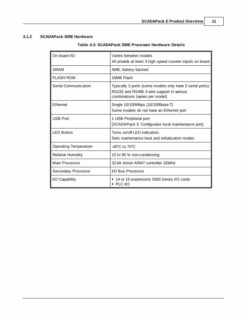
4.1.2 SCADAPack 300E Hardware
Table 4.3: SCADAPack 300E Processor Hardware Details
On board I/O Varies between models
All provide at least 3 high speed counter inputs on board
SRAM 4MB, battery backed
FLASH ROM 16MB Flash
Serial Communication Typically 3 ports (some models only have 2 serial ports)
RS232 and RS485 2-wire support in variouscombinations (varies per model)
Ethernet Single 10/100Mbps (10/100Base-T)
Some models do not have an Ethernet port
USB Port 1 USB Peripheral port
[SCADAPack E Configurator local maintenance port]
LED Button Turns on/off LED indicators.
Sets maintenance boot and initialization modes
Operating Temperature -40oC to 70oC
Relative Humidity 10 to 95 % non-condensing
Main Processor 32-bit Atmel ARM7 controller 32MHz
Secondary Processor I/O Bus Processor
I/O Capability 14 or 15 expansions 5000 Series I/O cardsPLC I/O

SCADAPack E Product Overview12
4.1.3 SCADAPack ES Hardware
Table 4.1: SCADAPack ES RTU Hardware Details
Feature Quantity Description
Dimensions L:300mm, W:175mm, D:40mm
Operating Temperature -40oC to +65oC 10-95% humidity
Input Power Supply
(fused)
Wide Range 10-30VDC 0.25-0.48A @ 24VDC isolated
0.50-0.96A @ 12VDC isolated
Output Power Supply
Option*
10VDC Option
24VDC Option
500 mA capacity isolated (fused)
230 mA capacity isolated (fused)
Hex Switches 2 Special processor modes and
Remote I/O address
Accessible when case removed
Digital Inputs 32, 16, 8 input models
Constant Current (sink)
7VDC – 48VDC
8 inputs channels per common
IEC60870-3 Class 1
Optically Isolated
Counter Inputs Up to 32 (digital input channels) Up to 50Hz
High Speed Counters Up to 8 (digital input channels) Up to 1kHz
Digital Outputs 16, 8, 4 output models
3 terminal Normally Open /Normally Closed contacts
Individual relay feedback
Relay Isolated
24VDC Max. 60W /
60VAC Max. 125VA
IEC60870-3 Class 3
Max 2A per relay (inductive)
Analog Inputs 12, 6, 4 input models
12-bit A/D conversion
0.1% accuracy
Isolated channel to channel
Optically isolated to RTU logic
0-20/4-20mA / 0-5V/1-5V/1-10V
Analog Outputs 4, 2 output models
12-bit D/A conversion
0.1% accuracy
Isolated channel to channel
Optically isolated to RTU logic
0-20mA / 4-20mA, voltage outputwith external resistor
Serial Communications 5 Async Serial Ports.
All ports support RS232.
Ports 2 and 3 support RS422 /RS485.
300-115200 bps
Static protection to IEC801-2
ETHERNET Interfaces 2 Interfaces @ 10/100 Mbit/sec RJ-45 UTP (100Base-T)
CPU 32-bit AMD Elan 586 Embeddedcontroller
100 MHz

SCADAPack E Product Overview 13
FLASH ROM 32 M-byte On-board programmable
NV RAM 2 M-byte Lithium battery backed
Volatile RAM 128 M-byte Dynamic SDRAM
Compact FLASH Ports(Type I)
1 up to 512 MB Compact Flash cardssupported.
I/O Capability On-board I/O
5000 I/O module bus
SCADAPack ES Remote I/O
PLC I/O

SCADAPack E Product Overview14
4.1.4 SCADAPack ER Hardware
Table 4.2: SCADAPack ER Processor Hardware Details
General Specifications as for SCADAPack ES above, with thefollowing:
SRAM 1MB, battery backed
SDRAM Dynamic 128MB
FLASH ROM 512K Boot ROM
16MB Flash
32MB Flash Optional
Serial Communication SCADAPack ER - P600:5 ports. All default to RS232.
Ports 2 and 3 can be selected for RS232 / RS 422 /RS485 operation.
Port 0 offers full RS232 hardware control
SCADAPack ER-P620:9 ports. All default to RS232.Port 0 offers full hardware flow control.
Ports 2,3,5,6,7,8 can be selected for RS232 / RS 422 /RS485 operation.
Ports 5,6,7,8 can be selected for Conitel Slave operation
IRIG-B time synchronization port
Ethernet Dual 10/100Mbps (10/100Base-T)
Hex Switches 2 - special processor modes
Accessible by removing processor card from the backplane.
Compact Flash 1 external Slot (standard)
Operating Temperature -10oC to 60oC
Relative Humidity 10 to 95 % non-condensing
Main Processor 32-bit AMD Elan 586 Embedded controller 100MHz
Secondary I/O Processor I/O Bus Processor i386EX 33MHz
Isolation 2.5KV - all interfaces
Insulation 2.5KV - all interfaces
I/O Capability 12 I/O card slotsSCADAPack ES Remote I/O
PLC I/O
System Maintenance Hot Swap I/O card exchange
Hot Swap Redundant dual Power Supply capable

SCADAPack E Product Overview 15
4.1.5 RTU Hardware Accessories
SCADAPack E RTU’s are typically used in conjunction with some of the following accessories:
External isolated power supply
Battery backup power supply with charging / discharge / test capability
Solar power supply
PSTN dial-up modem
GSM cellular modem
CDMA cellular modem
Leased-line modem
Trio Datacom(R) Data radio
Accutech(R) Wireless Sensors
Data radio
GPRS cellular data modem
1xRTT cellular data modem
HSDPA cellular data modem
Satellite communications
TCP/IP Internet / Intranet communications
PLC’s and other peripheral equipment

SCADAPack E Product Overview16
4.2 Operation
Basic facilities are provided by the SCADAPack E RTU to enable it be used in simple applications with aminimum of configuration. Advanced facilities are also provided for demanding applications. Support forthe following facilities allows the RTU to be used in a wide range of SCADA system architectures:
Communication Interfaces & Sequencing and Control
Data Acquisition & Remote Diagnostics and Configuration

SCADAPack E Product Overview 17
4.2.1 Communication Interfaces & Sequencing and Control
Communication InterfacesThe SCADAPack E RTU supports connection to a wide range of communication interfaces and services:
The following types of communication connections are supported by the RTU:
with 5000 I/O modules (SCADAPack ES and SCADAPack 300E only)
with PLC or other peripheral devices for gathering data or sending controls
with other local SCADAPack ES RTUs for expanding I/O capacity (known as Remote I/O)
with SCADA Master Station, via Communication Networks, for reporting current status, transferringhistorical data, receiving controls
with other RTUs, via Communication Networks, for coordinating distributed control (known as Peer-to-peer)
wide area communication networks, such as low-cost audio radio, leased line, leased digitalservices, data radio, GSM modem, GPRS modem, PSTN dial-up modem, satellite, internet, intranet,etc.
local area communication networks such as RS485, Ethernet, Fiber Optics
Industry standard protocol support is provided including DNP3, MODBUS, TCP/IP, etc.
Sequencing and ControlOn-board sequencing supports up to two user applications, both fully IEC61131-3 compliant, supportingthe five programming languages including extensive facilities for floating point mathematics, PID control,ASCII input and output, integration with Peer-to-Peer communications, etc.
SCADAPack E Product Overview18
4.2.2 Data Acquisition & Remote Diagnostics and Configuration
Data AcquisitionFlexible configurations allow data acquisition for each physical and derived RTU point to be individuallytailored. RTU data can be time-stamped by the RTU, transmitted to a SCADA Master station onexception, buffered for access via polling, stored in files for later retrieval, processed by the RTU to addvalue to the data, etc.
Remote Diagnostics and ConfigurationOperations that can be carried out locally, such as configuration, programming, debugging, diagnosis,and software upgrades can also be carried out to an RTU remotely through wide area and local areacommunication networks.

SCADAPack E Product Overview 19
4.3 RTU System Facilities
The major components of the SCADAPack E RTU provide a wide range of system facilities as follows. Refer to the appropriate Technical Reference manuals for detailed information about each component.
Point Database -contains configurations and current values for RTU points-contains Trend configuration records for trend sampling
I/O Sub-system -receives data from physical input channels and controls data to physical outputchannels on the local RTU I/O
Remote I/O -expands the I/O capacity of a SCADAPack ES or SCADAPack ER RTU byinterconnecting multiple SCADAPack ES units via Serial or Ethernet links
ISaGRAF -provides user sequencing and control support using IEC61131-3
-interfaces with DNP3 for peer-to-peer communication, and advanced manipulationof DNP3 communication parameters
-up to two (2) user applications may execute simultaneously
DNP3 -high reliability, open systems communication protocol
-provides RTU to SCADA Master communication
-transfers time-stamped historical records of point events
-polled and report-by-exception operation
-provides RTU to RTU peer communication
-carries configuration and diagnostic data including RTU Config
-carries 3rd party protocol using Virtual Terminal objects
Comm Interfaces -provides a number of communication interfaces for DNP3
-includes PSTN dial-up, GSM dial-up, keyed RS-232, PPP, GPRS, 1xRTT
PeripheralInterface
-provides communication services with PLC and peripheral equipment
-allows user applications to generate and receive ASCII data
-provides MODBUS Master & Slave communications
-provides Open MODBUS/TCP Client & Server communications
Data Processor -provides the RTU with integrated data processing and manipulation
-uses Point attributes to drive the data processing and sets Point properties withthe results of the processed data
-interfaces with DNP3 for event generation, storage and transmission
Profiler -manipulates point attributes and values based on time schedules
Trend Sampler -summarizes and stores historical records of point data
File System CommandInterface
- stores RTU data such as profiles, trend sample files, user applications
- provides user access to RTU commands and diagnostic information
- remotely accessible using either TELNET or over DNP3 using theSCADAPack E Configurator
TCP/IP -provides comms facilities and applications for Internet or Intranet networksthrough Ethernet (LAN) or serial (WAN) RTU interfaces.
-Integrates RTU facilities with standard TCP/IP applications for remotemanagement of the SCADAPack E RTU

SCADAPack E Product Overview20
4.4 SCADAPack E Configurator
SCADAPack E RTUs are maintained and diagnosed using Schneider Electric “SCADAPack EConfigurator” software package. SCADAPack E Configurator executes on PC hardware using MicrosoftWindows XP, Windows Server 2003, Windows Vista, Windows Server 2008, or Windows 7 32-bit or 64-bit operating systems, and provides graphical user interfaces for configuring and diagnosingSCADAPack E RTU’s.
SCADAPack E Configurator can create and modify configurations on-line with a SCADAPack E RTU oroff-line, saving configurations for loading into SCADAPack E RTU’s at a later time.
SCADAPack E Configurator application supports a wide variety of communication media access forremote communication with RTU’s.
Graphical forms are presented for each aspect of RTU configurations.
Ad-hoc user point enquiries may also be entered, commented, tailored and saved for individual RTUs.

SCADAPack E Product Overview 21
5 Physical I/O Expansion
The physical I/O of the RTU can be expanded in several ways.
SCADAPack 300E and SCADAPack ES controllers also supports connection of 5000 I/O modules.
Another method is to use SCADAPack ES RTUs as Remote I/O units whereby Main and Remote IORTUs are identified and grouped using the RTU HEX switches. SCADAPack ES RTU controllers can beused as Remote I/O devices to other SCADAPack ES RTUs and SCADAPack ER RTUs.
5000 I/O
SCADAPack ES REMOTE I/O

SCADAPack E Product Overview22
5.1 5000 Series I/O
The physical I/O of a SCADAPack ES RTU or SCADAPack 300E RTUs can be expanded by connecting 5000 I/O modules to the I2C I/O bus interface.
Configurations can be created OFFLINE and transferred to the SCADAPack E RTU. Theseconfigurations specify the modules to be used and the mapping of I/O points to the RTU database. The5000 I/O modules can be daisy-chained in order to expand the quantity of physical I/O as required.
The SCADAPack E RTUs supports up to 16 connected I/O modules (additional I/O bus power suppliesmay be necessary).

SCADAPack E Product Overview 23
5.2 SCADAPack ES REMOTE I/O
SCADAPack ES Remote I/O is a mechanism provided by the SCADAPack E RTU to expand the I/Ocapacity of a Main RTU unit using additional SCADAPack ES RTUs. Remote I/O units are configuredautomatically not requiring user configuration. Identification of Main and Remote I/O units is achieved bysetting the RTU HEX switches on SCADAPack ES RTUs.
The SCADAPack ER RTU can only be a Main RTU, but can utilise SCADAPack ES RTUs as remote I/Odevices.A SCADAPack ES RTU can be either a Main RTU and a Remote I/O unit.
In a Remote I/O system, one SCADAPack E RTU is a “Main” RTU unit, and others are “Remote I/O”units. Each Remote I/O “group” may have up to 15 Remote I/O units.
A Main RTU unit is a normal RTU, providing the complete range of RTU services.
Remote I/O units provide facilities for monitoring and controlling I/O on behalf of the Main RTU.
Communications are established between a Main RTU unit and its Expansion I/O unit(s) using a Serialor ETHERNET interface.
Figure 5.1: Typical RTU System using Remote I/O
6 IEC 61131-3 ISaGRAF
ISaGRAF 3 Workbench (target 3 firmware)SCADAPack Workbench (target 5 firmware)
6.1 ISaGRAF 3 Workbench
ISaGRAF 3 Workbench SoftwareISaGRAF 3 Workbench software is used to create, manage and simulate sequencing and controlapplications using the five (5) IEC61131-3 international standard PLC programming languages, using thetarget 3 firmware. ISaGRAF 3 Workbench CASE Tools provides an environment for complete off-lineapplication development. ISaGRAF 3 Workbench is compatible with Windows 2000 / XP.

SCADAPack E Product Overview24
The ISaGRAF 3 Workbench debugger loads IEC 61131-3 application programs to the target(SCADAPack E RTUs in this case) and also provides on-line target application debugging facilities.
Up to two independent ISaGRAF user applications can be loaded in to the same SCADAPack E RTU.
ISaGRAF 3 Workbench CommunicationThe ISaGRAF 3 Workbench debugger operates with SCADAPack E RTU’s on a serial port, via Ethernet,and remotely via the SCADAPack E Configurator DNP3 data communication channel to RTUs.

SCADAPack E Product Overview 25
6.2 SCADAPack Workbench
SCADAPack Workbench SoftwareSCADAPack Workbench software is used to create, manage and simulate sequencing and controlapplications using four (4) IEC 61131-3 international standard PLC programming languages and thetarget 5 firmware. SCADAPack Workbench is compatible with Windows XP SP3, Windows Server2003, Windows Vista, Windows Server 2008, and Windows 7 operating systems.
The SCADAPack Workbench debugger loads IEC 61131-3 application programs to the target 5 resource(SCADAPack E RTUs in this case) and also provides on-line application debugging facilities.
Up to two independent resources can be loaded in to the same SCADAPack E RTU.
SCADAPack Workbench CommunicationThe SCADAPack Workbench debugger operates with SCADAPack E RTU’s via serial or Ethernet.

SCADAPack E Product Overview26
7 DNP3 - Distributed Network Protocol
DNP3 SCADA Protocol Standard & RTU DNP3 Support
DNP3 Networking

SCADAPack E Product Overview 27
7.1 DNP3 SCADA Protocol Standard & RTU DNP3 Support
DNP3 SCADA Protocol StandardDNP3 (Distributed Network Protocol) is an industry standard SCADA communications protocol. DNP3 isin widespread use in many industries across the world and is managed by the internationallyrepresented DNP User Group. It describes standards for SCADA protocol facilities such as polling, ad-hoc data requests, controls, and report by exception (RBE). Master-slave and Peer-to-Peercommunication architectures are supported by DNP3.
Inter-operability is one of the key aspects of DNP3, which is enforced by way of minimumimplementation subsets to which vendors need to adhere. The DNP3 protocol also caters for expansion& evolution using object-oriented approach to the data. For further information see the DNP User GroupWeb Site at www.dnp.org.
RTU DNP3 SuppportThe SCADAPack E RTU supports as a minimum, DNP3 communication protocol facilities to DNP3Subset Level 2 with a range of additional features being provided from the DNP3 standard.
In summary the RTU provides the following facilities for use of DNP3:
Polling, Report by Exception, Unsolicited Response transmission to SCADA Master
Simultaneous DNP3 operation on Multiple SCADAPack E RTU communication Ports
Networking (Routing) of DNP3 frames
Peer-to-Peer interchange of data between RTU nodes
Wide range of DNP3 data objects including:
o integer and floating point analog objects
o counter objects
o file identifier object
o virtual terminal objects
DNP3 Multi-Master support (licensing required)

SCADAPack E Product Overview28
7.2 DNP3 Networking
Communications received by a SCADAPack E RTU may be re-directed to other SCADAPack E RTUcommunication ports based on routing.
SCADAPack E RTUs are capable of routing DNP3 frames, and can be configured with network routingtable entries for this purpose. Backup communication links may also be configured.
Figure 7.1 and Figure 7.2 shows typical SCADAPack E RTU Network using DNP3 routing.
SCADAPack E RTU’s may send Peer messages to other SCADAPack E RTU in the network.
For example, DNP #200 may communicate with Peer DNP #301. In this case, SCADAPack E RTU’sDNP #101 and DNP #103 route the DNP3 frames between the various communication sub-networks. The Master station may also communicate transparently with any node in the communication network,with DNP nodes #101 and #103 routing DNP3 frames to RTU’s on different communication sub-networks, as required.
Figure 7.1: Typical SCADAPack E RTU Network using DNP3 Routing for Peer Communication

SCADAPack E Product Overview 29
Figure 7.2: Typical SCADAPack E RTU Network Master – RTU Communications

SCADAPack E Product Overview30
8 RTU Communication
DNP3 Communication Interfaces
Peripheral Device Communication Interface

SCADAPack E Product Overview 31
8.1 DNP3 Communication Interfaces
Communication with SCADAPack E RTUs using DNP3 can be accomplished through several physicalinterfaces: Direct physical interfaces, Multi-drop physical interfaces, Hayes Modem interfaces and,optionally, ETHERNET interface. Multiple interfaces may be used simultaneously on the same RTU.
Port Interface types using RTU direct communication interfaces include RS232 / RS422, dial-up modem,GPRS. 1xRTT, Port Interface types using RTU multi-drop communication drivers include: KeyedRS232, RS485, ETHERNET.
Hayes Modem Communication

SCADAPack E Product Overview32
8.2 Hayes Modem & Mobile IP Communication
Hayes Modem CommunicationThe SCADAPack E RTU can provide DNP3 network communications using Hayes Modemcommunications. This type of RTU communication is often called “PSTN” (Public Switched TelephoneNetwork) or dial-up communication. Similarly "GSM" (Global System for Mobile communication) usesHayes Modem communication. Both PSTN and GSM require the use of commercial modem equipment.Both dial-in and dial-out operation is supported for SCADA Master, Peer-to-Peer communicationbetween RTU’s, or for configuration or diagnosis using the SCADAPack E Configurator software. Specific support is provided for low-powered modems.
Mobile IP CommunicationThe SCADAPack E RTU supports IP communication through mobile IP technology such as GRPS (overGSM cellular communication networks) and 1xRTT (over CDMA cellular communication networks).
See also TCP/IP Networking

SCADAPack E Product Overview 33
8.3 Peripheral Device Communication Interface
SCADAPack E RTU’s can communicate with Peripheral devices, such as PLC's and instruments, invarious ways.
MODBUS Slave, & Master and Peripheral Operation
MODBUS/TCP Client Operation
IEC 60870-5-101 & 104 Slaves

SCADAPack E Product Overview34
8.3.1 MODBUS Slave, & Master and Peripheral Operations
MODBUS Slave OperationThe SCADAPack E RTU supports communications using MODBUS RTU Slave protocol. The nativeMODBUS Slave driver can function simultaneously on multiple ports and maps directly to the RTU’spoint database. This MODBUS Slave implementation does NOT require ISaGRAF. Consult the ISaGRAF3 Modbus Communication Interfaces Manual or the SCADAPack E Target 5 ModbusCommunication Interfaces manual documents for more information.
MODBUS Master OperationThe SCADAPack E RTU can operate as a Master when communicating with PLC or peripheral devices. Various protocols can be supported between the SCADAPack E RTU and peripheral devices viaISaGRAF PLC Device I/O boards. For example, RTU ISaGRAF MODBUS PLC I/O Boardscommunicate to PLC’s using MODBUS RTU Master protocol.

SCADAPack E Product Overview 35
8.3.2 MODBUS/TCP Client & Server Operations
MODBUS/TCP Client OperationMODBUS/TCP Client operation allows a SCADAPack E RTU to utilize ISaGRAF PLC I/O boards togenerate requests to MODBUS/TCP server devices such as PLCs, block I/O devices, etc.
For example, the SCADAPack E RTU can read data from, or write data to Open Modbus/TCPConformance Class 0 or Class 1 Ethernet PLCs.
In addition, BOOTP server facilities are supported by the SCADAPack E RTU for providing Ethernetnetwork configuration of devices such as block I/O units.
For example, PLC I/O blocks can be used as remote I/O for SCADAPack E RTUs. Up to 20 I/O blockscan be connected to the same SCADAPack E RTU.
MODBUS/TCP Server OperationMODBUS/TCP Server operation allows a SCADAPack E RTU data to be made available to MODBUS/TCP client devices such as a local SCADA master station, or Ethernet PLCs. Using this facility, theRTU can be used like a full-featured Ethernet PLC, or like an I/O module. Other than enabling theMODBUS/TCP Server, no additional configuration is required to access RTU point data. RTU physical,derived and system points can be accessed and controlled via the MODBUS/TCP server.

SCADAPack E Product Overview36
8.3.3 MODBUS RTU in TCP Client Operations
Modbus RTU in TCP Client operation allows a SCADAPack E RTU to utilize ISaGRAF PLC I/O boardsto generate requests to Modbus RTU in TCP server devices such as PLCs, block I/O devices, etc.
In addition, BOOTP server facilities are supported by the SCADAPack E RTU for providing Ethernetnetwork configuration of devices such as block I/O units.
For example, PLC I/O blocks can be used as remote I/O for SCADAPack E RTUs. Up to 20 I/O blockscan be connected to the same SCADAPack E RTU.
8.3.4 IEC 60870-5-101 & 104 Slaves
IEC 60870-5-101 SlaveThe SCADAPack E RTUs support the IEC 60870-5-101 protocol whereby the RTU functions as a Slavedevice (licensing required). The RTU can support up to 2 IEC 60870-5-101 Masters simultaneouslyconnected. The mapping of the Information Object Address (IOA) and Application Service Data Unit(ASDU) type to RTU point numbers is determined by point configurations. Refer to the SCADAPack EIEC 60870-5-101 / -104 Slave Technical Reference manual and the SCADAPack E IEC 60870-5-101Slave Interoperability document for more information.
IEC 60870-5-104 SlaveThe SCADAPack E RTUs support the IEC 60870-5-104 protocol whereby the RTU functions as a Slavedevice (licencing required). The RTU can support up to 2 IEC 60870-5-104 Masters simultaneouslyconnected. The mapping of the Information Object Address (IOA) and Application Service Data Unit(ASDU) type to RTU point numbers is determined by point configurations. Refer to the SCADAPack EIEC 60870-5-101 / -104 Slave Technical Reference manual and the SCADAPack E IEC 60870-5-104Slave Interoperability document for more information.
SCADAPack E Product Overview 37
9 RTU Data Processing
RTU Data Processing FacilitiesThe following summarizes the data processing facilities for manipulation of SCADAPack E RTU physicalpoint data or derived data:
Physical Digital Input De-bounce Physical Digital Input Invert
Into Alarm Time dead-band Integer scaling range & Engineering scaling range
Point Quality Over-range detection, Under-range detection
Multiple Engineering Alarm Limits Software Counters with de-bounce & Invert
Out-of-Alarm Time dead-band Out-of-Alarm Value dead-band
Alarm Inhibit, Trend Inhibit Rate Of Rise, Rate Of Fall, No Change detection
Remote Control Interlock Event generation on Significant Change Deviation
Output Pulse time
ProfilerThe SCADAPack E RTU Profiler allows the RTU to manipulate values and attributes of binary, analogand counter data points based on time profiles. The Profiler provides time-based control of data pointson a time-of-day and day-of-week basis. The time information is stored in files in the SCADAPack ERTU File System that schedule changes to point attributes.
Trend SamplerThe SCADAPack E RTU Trend Sampler allows RTU data points to be periodically sampled, the valuesbeing recorded in files in the RTU File System. The storage of data using this mechanism provides amore sophisticated and efficient data storage mechanism than is provided by DNP3 Event storage. Multiple trend streams on the same RTU point are supported, including a variety of statistic types, and/or trend rates. Trend samples may include data quality information.
Time ConversionUTC or Standard Time can be used in the RTU Real Time Clock. Conversion from UTC to Local Time isprovided, with facilities for Summer time activities through ISaGRAF and Profiler if required.

SCADAPack E Product Overview38
10 TCP/IP Networking
The SCADAPack E RTU supports TCP/IP networking and communications integration. The RTUconforms to the relevant IEEE and TCP/IP RFC standards, and may be used in a wide range of LAN andWAN topologies, including systems using Routers, Bridges, Terminal Servers, Hubs, Switches, etc.
The following TCP/IP networking facilities are available with the SCADAPack E RTU:
PPP serial communications including extensive options negotiation
LCP echo (PPP link status) via command line & ISaGRAF function block
Ethernet TCP/IP communications including ARP
GPRS (General Packet Radio Service) and 1xRTT cellular data interfaces
ICMP support including PING server
PING client via command line & ISaGRAF function block
IP forwarding between TCP/IP interfaces (eg. PPP to PPP, PPP to ETH, etc.)
IP routing table, configurable via RTU configuration, command line and ISaGRAF
BOOTP server capability for configuring network device addresses across an Ethernet network,configurable via RTU configuration or command line
TCP/IP diagnostics on the RTU diagnostic stream, including selectable filtering
UDP and TCP transport over IP
DNP3 integration with TCP/IP as per DNP User Group requirements for DNP3 over LAN/WAN TCP/IP networks
ISaGRAF Workbench debugger using TCP (eg. via PPP links, Ethernet, etc)
MODBUS/TCP client providing connectivity for SCADAPack E RTUs with Ethernet PLC systemsand I/O brick units. The RTU conforms with the Open Modbus/TCP specification for Class 0 andClass 1 devices
MODBUS/TCP server allowing the SCADAPack E RTU to operate like an Ethernet PLC or EthernetI/O. Supports Open Modbus/TCP Class 0 and Class 1 standard
TCP Service Port server allows the SCADAPack E RTU to operate like a terminal server, with a hostopening application serial ports on the RTU. TCP Service Port client is also supported allowing theRTU to transport any serial protocol across a network
TELNET server accesses the RTU command-line and diagnostic stream (multiple users supportedsimultaneously)
FTP server accesses the RTU file system (multiple users supported simultaneously)
NTP Network Time synchronization support (client and single/multiple server synchronizationsupported)
Security for denying and permitting RTU TCP/IP services.
IEC 60870-5-104 slave (up to 2 simultaneous server connections supported)

SCADAPack E Product Overview 39
11 RTU Diagnostics
An extensive range of diagnostic, status and statistical information is provided by the SCADAPack ERTU’s in order to facilitate trouble-shooting and understanding of the SCADAPack E RTU operation.
The RTU, through the Diagnostic Display session, indicates operating diagnostics for:
DNP3 diagnostics at each protocol layer including network routing
TCP/IP diagnostics
PLC communication diagnostics
RTU system diagnostics
AGA12-2 diagnostics
Status information is available from various RTU facilities including:
DNP3 communication status
PLC Device communication status
RTU system status
RTU IO status
ISaGRAF user application status
TCP/IP status

SCADAPack E Product Overview40
12 Data Concentrator (Master Protocol Support)
The SCADAPack E RTU can be configured as a Data Concentrator where the RTU behaves as aprotocol master, managing the communications and polling regimes to other remote devices. Thisapproach abstracts the remote SCADA master from the remote devices, allowing the SCADA master toregularly communicate with only the data concentrator. The RTU configuration determines the mappingof remote outstation points / objects to configuration points in the data concentrator. The protocolscurrently supported for outstation communications using the Data Concentrator are listed as follows
DNP3
IEC 60870-5-103
SCADAPack ES Remote I/O (Connection supported by SCADAPack ES and SCADAPack ER only,not SCADAPack 300E)
Refer to the SCADAPack E Data Concentrator Technical Reference manual for more informationregarding the Data Concentrator.
MODBUS Master and MODBUS/TCP client operations are supported using ISaGRAF I/O boards. Thisis discussed in Sections MODBUS Slave, & Maser and Peripheral Operations (Master andPeripheral Operation) and MODBUS/TCP Client & Server Operations MODBUS/TCP ClientOperation.

SCADAPack E Product Overview 41
13 Security
The SCADAPack E RTU supports SCADA security through DNP3 Secure Authentication and/or theAGA12-2 Encryption.
These security protocols are integrated with the various operational aspects of the RTU.
DNP3 Secure Authentication and AGA12-2 Encryption security on SCADAPack E RTUs applies only toDNP3 communications. These may be used independently to improve the protection provided by DNP3,or may be used concurrently for maximum protection.
Integrated security is a licensed feature of the SCADAPack E RTUs. After licensing, integrated securityis activated when a security configuration is loaded in to the device.
Refer to the SCADAPack E Security Technical Reference for detailed information regarding Securityfunctions, DNP3 Secure Authentication and AGA12-2 Encryption.
Configuration of security settings is managed through centralized Security Administrator software.Typically security administration personnel would maintain strict control over this application. For moreinformation see Security Administrator User Manual.

SCADAPack E Product Overview42