scaffolding assembly, use and dismantling general … · euro foster cofraj srl assembling, use and...
TRANSCRIPT

SCAFFOLDING ASSEMBLY, USE AND DISMANTLING GENERAL PLAN
PIMUS
USER CONTRACTOR COMPANY: - SCAFFOLDING ASSEMBLING COMPANY: -
Type of scaffold: - Place of Assembly -

EURO FOSTER COFRAJ SRL Assembling, Use and Dismantling Plan 1.1
TABLE OF CONTENTS
1. PURPOSE ................................................................................................................. 1.2
1.1 SCOPE 1.2
1.2 RESPONSIBILITIES 1.2
1.3 REFERENCES 1.4
2. GENERAL DESCRIPTION ......................................................................................... 2.7
3. TECHNICAL CHARACTERISTICS OF THE MATERIAL ............................................... 3.8
4. DESIGN. ................................................................................................................ 4.16
5. GENERAL CONSIDERATIONS ............................................................................... 5.19
5.1 General considerations regarding the human and material means for the proper
execution of the assembly process. 5.19
5.2 Coordination of business activities. 5.19
6. DEVELOPMENT OF THE ASSEMBLY, USAGE AND DISASSEMBLY PROCEDURE.... 6.20
6.1 Elements for understanding the Resablok scaffolding Assembly and Disassembly
Drawings. 6.20
6.2 Method for safely securing the fall-arrest harness 6.22
6.3 Loading and Unloading Materials On Site. Load hoisting, displacement, and
placement processes. 6.23
6.4 Operating Assembly and Disassembly Method. 6.26
6.5 Weather Conditions that may affect during Assembly and Disassembly operations. 6.31
7. RISK ASSESSMENT AND PREVENTIVE MEASURES ................................................. 7.34
7.1 Definitions 7.34
7.2 General Risks 7.35
7.3 Risk Related Information and Planning of Preventive Measures in Scaffold Assembly-
Disassembly Operations. Work Position: Scaffold Erector. 7.38
7.4 Individual Protection Equipment. 7.43
7.5 Signpostings 7.50
8. DRAWINGS ........................................................................................................... 8.55
9. TECHNICAL DATA OF THE MANUFACTURER ........................................................ 9.56
9.1 Resablock multidirectional scaffolding system. 9.56
9.2 Manufacturer 9.56
10. ANNEXES ............................................................................................................ 10.57

EURO FOSTER COFRAJ SRL Assembling, Use and Dismantling Plan 1.2
1. PURPOSE
The purpose of this document is to ensure that all company workers whose activities include
works in the reference scaffolding are properly instructed in prevention matters and in the
design, assembly, use and disassembly thereof.
Information will be provided on the specific risks involved in the works implied in the assembly,
use and disassembly of scaffolding. The minimum safety and health provisions will be
established, in order to minimize the risks entailed by said works.
1.1 SCOPE
The provisions of this Assembly Plan will have to be observed by all eventual scaffold users
during the assembly, usage, and disassembly phases, and also by all workers involved in
completed work inspection tasks, where appropriate.
1.2 RESPONSIBILITIES
Euroresa Schele SRL is responsible for guaranteeing that all its workers are properly trained
and instructed in all safety related matters during the scaffold assembly, usage, and
disassembly stages.
Site Manager.
a) Will enforce adequate procedure compliance.
b) Will lead and verify the results of the revisions and corrective actions established.
c) Will allocate or request the Management to allocate the human and/or material means
required for the application of the corrective measures.
Superintendent, Team Leader, Foreman or Officer leading the assembly process.
This person or function is considered to be a “competent person”, as regards the verification
of the requirements established in the checklist and assembly drawings, where appropriate,
and will therefore assume the following responsibilities:
a) Verifying the aforementioned requirements.
b) Filling out the check-list fill out and posting by scaffolding accesses.
c) Posting of usage prohibition signs during the assembly phase and whenever non-
conformities are detected.
d) Establishing and executing corrective measures.
In order to supervise, guide, and verify the assembly, disassembly and/or alteration
operations an university or professional degree providing proof of capacity for such tasks will be
required. By “professional training” we understand a certified background of more than two
years in a similar position, which will need to be complemented by means of the completion of
a Basic Level training Occupational Risk Prevention course, in compliance with RD 39/1997).

EURO FOSTER COFRAJ SRL Assembling, Use and Dismantling Plan 1.3
Direct Workers.
a) Will collaborate in inspectio tasks, notifying immediate supervisors of any unsafe
condition detected in the installation.
b) Only workers that provide adequate proof of proper and specific training shall take
part in scaffolding assembly works, in compliance with the provisions established in
RD 2177/2004.
Client
a) Will collaborate for a successful procedure implementation, supporting the
establishment of pertinent controls in order to ensure:
b) That scaffolding elements are not modified. Both Client or User Company expressly
agree not to alter the scaffold in anyway whatsoever. Any type of such alteration is
strictly forbidden.
c) Will put the scaffold out of service and prevent access to it by placing the opposite
side of the check-card, or fitting out warning tape, whenever a non-conformity is
detected on it.
d) Will subject the scaffold to inspections by competent personnel, whenever Euroresa
Schele SRL is not contractually commissioned to conduct them.
e) Will immediately notify Euroresa Schele SRL of any deficiency detected in the scaffold
in order to have it corrected.
EURO FOSTER COFRAJ SRL Assembling, Use and Dismantling Plan 1.4
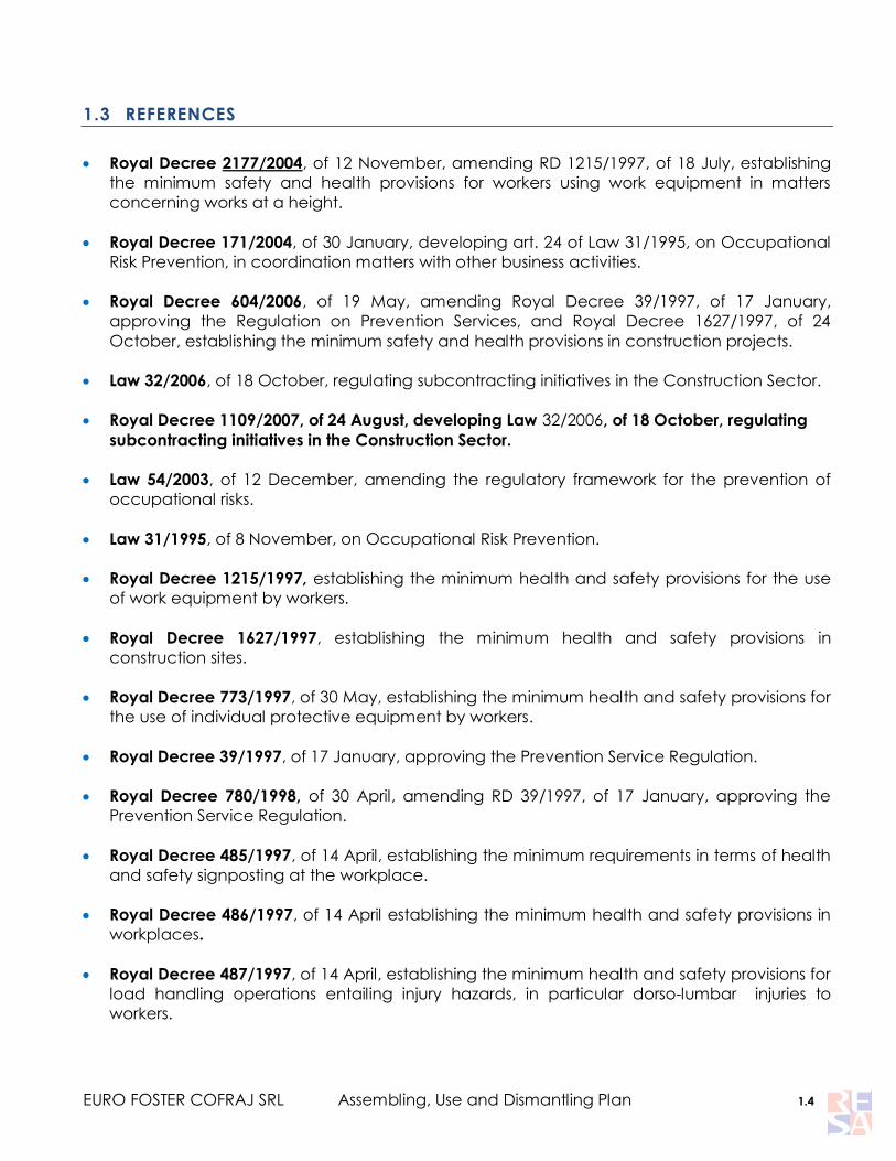
1.3 REFERENCES
Royal Decree 2177/2004, of 12 November, amending RD 1215/1997, of 18 July, establishing
the minimum safety and health provisions for workers using work equipment in matters
concerning works at a height.
Royal Decree 171/2004, of 30 January, developing art. 24 of Law 31/1995, on Occupational
Risk Prevention, in coordination matters with other business activities.
Royal Decree 604/2006, of 19 May, amending Royal Decree 39/1997, of 17 January,
approving the Regulation on Prevention Services, and Royal Decree 1627/1997, of 24
October, establishing the minimum safety and health provisions in construction projects.
Law 32/2006, of 18 October, regulating subcontracting initiatives in the Construction Sector.
Royal Decree 1109/2007, of 24 August, developing Law 32/2006, of 18 October, regulating
subcontracting initiatives in the Construction Sector.
Law 54/2003, of 12 December, amending the regulatory framework for the prevention of
occupational risks.
Law 31/1995, of 8 November, on Occupational Risk Prevention.
Royal Decree 1215/1997, establishing the minimum health and safety provisions for the use
of work equipment by workers.
Royal Decree 1627/1997, establishing the minimum health and safety provisions in
construction sites.
Royal Decree 773/1997, of 30 May, establishing the minimum health and safety provisions for
the use of individual protective equipment by workers.
Royal Decree 39/1997, of 17 January, approving the Prevention Service Regulation.
Royal Decree 780/1998, of 30 April, amending RD 39/1997, of 17 January, approving the
Prevention Service Regulation.
Royal Decree 485/1997, of 14 April, establishing the minimum requirements in terms of health
and safety signposting at the workplace.
Royal Decree 486/1997, of 14 April establishing the minimum health and safety provisions in
workplaces.
Royal Decree 487/1997, of 14 April, establishing the minimum health and safety provisions for
load handling operations entailing injury hazards, in particular dorso-lumbar injuries to
workers.

EURO FOSTER COFRAJ SRL Assembling, Use and Dismantling Plan 1.5
Royal Decree 1407/1992, of 20 October. List and standards adopted within the scope of
Community Directive 89/686/EEC, of 28 May 1996.
Royal Decree 842/2002, of 2 August, approving the Low Voltage Electrotechnical
Regulations.
Royal Decree 1494/1986, of 26 May, approving the Machinery Safety Regulations.
Royal Decree 1435/1992, of 27 November, establishing the application requirements
concerning Council Directive 89/392/EEC, on the approximation of the laws of the Member
States relating to machinery.
Royal Decree 56/1995, of 20 January, amending RD 1435/1992.
Royal Decree 286/2006, of 10 March, on protecting worker health and safety from noise
exposure-related risks
UNE-EN 341: Fall arrest individual protection equipment. Descender devices.
UNE-EN 353-1: Personal fall protection equipment. Part 1. Guided type fall may arresters
including a rigid anchor line.
UNE-EN 353-2: Personal fall protection equipment. Part 2: Guided type may arresters
including a flexible anchor line.
UNE-EN 354: Personal fall protection equipment. Lanyards.
UNE-EN 355: Personal fall protection equipment: Energy absorbers.
UNE-EN 360: Personal fall protection equipment: Retractable type may arresters.
UNE-EN 361: Personal fall protection equipment: Fall arrest harnesses.
UNE-EN 362: Personal fall protection equipment: Connectors.
UNE-EN 363: Personal fall protection equipment: Fall arrest systems
UNE-EN 364: Personal fall protection equipment. General requirements for instructions for use
and marking.
UNE-EN 76501-1987: Auxiliary and detachable steel structures. Classification and definition.
UNE-EN 76502-1990: Service and working scaffolds made of prefabricated elements.
material, dimensions, design loads and safety requirements.
UNE-EN 76503-1991: Couplers, loose spigots and base-plates for use in working scaffolds and
falsework made of steel tubes. Requirements and test procedures.
UNE-EN 76505-1991: Steel tubes for falsework and working scaffolds. Characteristics and
tests.

EURO FOSTER COFRAJ SRL Assembling, Use and Dismantling Plan 1.6
UNE-EN 12810-1: 2005. Façade scaffolds made of prefabricated components. Part 1:
Product specifications.
UNE-EN 12810-2: 2005. Façade scaffolds made of prefabricated components. Part 2:
Particular methods of structural design.
UNE-EN 12811-1: 2005. Temporary works equipment. Part 1: Scaffolds - Performance
requirements and general design
UNE-EN 12811-2: 2005. Temporary works equipment. Part 2: Information on materials.
CTE: Technical Building Code (Código Técnico de Edificación).
*Order 2988/1998, of the Economy and Employment Council of the Community of Madrid
on the assembly, usage, maintenance, and preservation of tubular scaffolds.
Reference Regulation
FR-PG-20-08 Grupo Resa

EURO FOSTER COFRAJ SRL Assembling, Use and Dismantling Plan 2.7
2. GENERAL DESCRIPTION
Assembly Location:
Type of scaffold: Suspended Scaffold
Works to be carried out on the scaffold Maintenance tasks on the Wind Turbine's Mast.
The assembly will be carried out using a multidirectional Resablok scaffold, a scaffolding
system designed and manufactured by Grupo Resa.
The Resablok multidirectional scaffolding system is certified by Bureau Veritas, in compliance
with effective standards.
The following sections will provide the specific details on the technical characteristics of the
elements that will be used in the assembly, the design considerations, calculation justifications –
where appropriate – assembly, usage and disassembly procedures, safety considerations, etc.
For more information, please contact:
-
Euro Resa
www.gruporesa.es

EURO FOSTER COFRAJ SRL Assembling, Use and Dismantling Plan 3.8
3. TECHNICAL CHARACTERISTICS OF THE MATERIAL
The Resablok multidirectional scaffolding system consists of standard tubular elements,
joined together by means of a node-wedge couplet system, which yields a light but fully-rigid
structure.
One of the main conceptual advantages that it offers is its great level of versatility, being
capable of adapting to any situation, no matter how complex and diverse it is.

EURO FOSTER COFRAJ SRL Assembling, Use and Dismantling Plan 3.9

EURO FOSTER COFRAJ SRL Assembling, Use and Dismantling Plan 3.10

EURO FOSTER COFRAJ SRL Assembling, Use and Dismantling Plan 3.11

EURO FOSTER COFRAJ SRL Assembling, Use and Dismantling Plan 3.12

EURO FOSTER COFRAJ SRL Assembling, Use and Dismantling Plan 3.13

EURO FOSTER COFRAJ SRL Assembling, Use and Dismantling Plan 3.14

EURO FOSTER COFRAJ SRL Assembling, Use and Dismantling Plan 3.15
References: Resablok Handbook

EURO FOSTER COFRAJ SRL Assembling, Use and Dismantling Plan 4.16
4. DESIGN.
In order to design the scaffold, with the participation of the Delegation‟s Technical Supervisors
and the collaboration, if necessary, of the Engineering&Innovation Department, the
appropriate established procedures will be followed, in order to guarantee the quality of both
the activities and the results:
Specific design of the geometric configuration.
Structural calculation.
For this purpose, the particular characteristics of the scaffolding structure that is to be installed
will be taken into account:
Type of Scaffold Suspended Scaffold.
Configuration: -
Use: -
Loading/unloading/stock
location -
Type of scaffold:
Soil characteristics: -
Possibility of
configuration of the
bracing elements
-
Assembly Location:
Use of protection nets: -
Client specifications -
Other considerations -

EURO FOSTER COFRAJ SRL Assembling, Use and Dismantling Plan 4.17
In general terms, the “standard tubular scaffolding configuration’ – TYPE – does not require
any specific design configuration or structural calculation.
‘Standard tubular scaffolding configuration‟ means the scaffolding which, during the
periodical product certification process to which Grupo Resa subjects its different scaffolding
systems, has been specifically designed, calculated, and comprehensively tested for the
purposes it serves.
The results of the certification processes are included in the corresponding ‘Product
Handbook’ of each scaffolding system manufactured by Grupo Resa.
Similarly, the different use configurations covered in the „Product Handbook‟ corresponding
to each scaffolding model manufactured by Grupo Resa do not require either a specific design
or a particular structural calculation.
Generally, design and development results are detailed in the following documents,
among others:
Drawings
Calculation sheets.
Design and Development results will be reviewed, verified, and validated in compliance
with the procedures established by Grupo Resa, or with those established in agreement with
Client, especially those that may have been subject to modifications, which shall be reflected
in the same manner.
Any change made to a document will result in a new version thereof, which will be subject
to the review and verification process, for approval and validation, when appropriate.
Reference Procedure
PG-20 – Grupo Resa (in compliance w/UNE EN ISO 9000:2000)

EURO FOSTER COFRAJ SRL Assembling, Use and Dismantling Plan 4.18

EURO FOSTER COFRAJ SRL Assembling, Use and Dismantling Plan 5.19
5. GENERAL CONSIDERATIONS
5.1 General considerations regarding the human and material means for the
proper execution of the assembly process.
Human Means: As a general rule, work teams will be comprised by at least three
workers.
Required work
equipment:
Hand tools, namely: Drills, grinders, material hoisting means, if
necessary.
Assembly Location:
5.2 Coordination of business activities.
RD 171/04 establishes the mechanisms for the proper coordination of our activities with those of
our clients and contractors.
The mechanisms established for guaranteeing said coordination will be the following:
RESA will provide information on the risks arising from its activities (by providing the
applicable part of its Risk Assessment) and information on the Emergency Measures.
Coordination meetings set up by the client company will be attended by RESA
representatives.
Mandatory procedures for personnel accessing client facilities, specific work requests,
required authorizations for hot works, etc., will be complied with.
On the other hand, RESA will receive information on:
The risks entailed by the activities of other concurrent companies (if any)
Work center risks.
Emergency Plans in the work center.
All the foregoing, regardless of any other means that may be established by other
concurrent companies in the work center, or which my be established as a result of collective
bargaining processes, and of those established in the occupational risk prevention regulations
for certain industries and activities.
Reference Procedure
PG-16 Grupo Resa

EURO FOSTER COFRAJ SRL Assembling, Use and Dismantling Plan 6.20
6. DEVELOPMENT OF THE ASSEMBLY, USAGE AND DISASSEMBLY PROCEDURE
6.1 Elements for understanding the Resablok scaffolding Assembly and
Disassembly Drawings.
As a first step, it is important to become familiar with the materials that we will be working with,
as well as the function that each one of them is entrusted with from a safety point of view.
The Resablok multidirectional scaffolding system consists of of standard tubular elements, joined
together by means of a node-wedge couplet system, which yields a light but fully-rigid
structure.
One of the main conceptual advantages it offers is its great level of versatility, being capable
of adapting to any situation, no matter how complex and diverse it is.
RBN Series
RBP Series
Fixing the wedbe with hammer

EURO FOSTER COFRAJ SRL Assembling, Use and Dismantling Plan 6.21
The elements that make up the system are referenced in the foregoing section „Material
Characteristics”
Further references are available in the „Resablok Product Handbook‟.
The following table provides a schematic and summarized description of the functionality of the
most important components from a structural and safety point of view.
1 Screw Jack 7 Plat. De Paso
2 Standards 8 Deck
3 Ledger 9 Light beam
4 Foot guard 10 Diagonal brace
5 Cantilever 11 Reinf.ledger
6 Ladder
It is necessary to take into account that the above referred elements make reference to a
basic configuration, which can be complicated to a much further extent, involving greater
number of additional elements such as cantilevers, beams, string pieces, etc.
FUNCTION RESABLOK
STRUCTURAL
ELEMENTS
Support Fixed adjustable base / rotating adjustable base for inclined
surfaces / Adjustable base with wheels
Structure
Standards
Ledgers and reinforced ledgers.
Light beams
Rigidity Diagonal bracing
BRACING Stabilization / Absorption of
horizontal loads Anchoring to vertical wall, metal structure, concrete works, etc.
PLATFORMS
Work surface / rigidity Resting on ledgers / LR
Access System
By means of a inter-level ladder and transit platform with trapdoor
or by means of an attached staircase.
PROTECTION
ELEMENTS
Object fall arrest Skirting board and steel mesh
Personal fall arrest Ledgers
Person fall arrest during
assembly Safety guardrails

EURO FOSTER COFRAJ SRL Assembling, Use and Dismantling Plan 6.22
6.2 Method for safely securing the fall-arrest harness
This section provides a reminder of the basic rules to secure the fall-arrest harness in safe
conditions:
First rule: Put collective protection before individual protection by observing all assembly
instructions, which means that, for a proper scaffold assembly process, before accessing the
following level of the structure, it will be necessary to fully complete the lower level, in a way
such that it is possible to access the upper level using the corresponding ladder.
Brace the structure following assembly instructions. The hook accompanying the fall-arrest
system is designed to be secured to tubular structures. But, for such purpose, IT IS ESSENTIAL to
have the structure properly braced in order to render it capable of bearing, if necessary, the
impact resulting from the fall of an operator. For instance, a worker weighting 80 Kgs. falling,
once the two-meter safety line is completely stretched will result in a 600 kg force. exerted over
the element to which it is secured. Evidently, if the scaffold is not properly anchored, it could tip
over.
In general terms, the rules to ensure proper bracing of the structure to the wall are the following:
a) Brace every two meters in height in all rows, and every three m in every row of overhang
zones.
b) Brace every four meters in height in all rows.
c) In the upper end of the scaffold it is important to place anchors in all frames or standard
ends.
d) Always tie the feet of the top and end levels.
e) In any case, ties must be uniformly distributed throughout the whole scaffold surface.
f) The anchor system, depending on the wall circumstances will be secured either by
means of wall plugs, or by a tube and clamp assembly. If wall plugs are used, it will be
necessary to take into account that they must be fitted out in the most resistant parts of
the wall (formworks); in these points, as well as the anchors fitted out in reinforced
concrete walls, each anchor must be capable of bearing, as reference, 500 kg.
Scaffold anchor points. Before anchoring the harness, it will be necessary to make sure that the
piece has been properly assembled, and that lower levels are completely assembled. Once
the scaffold is stabilized by means of the aforementioned bracing, we can secure the hook of
the harness to the rosette of the upright poles or the guardrails (never in diagonal braces nor
toe guards).
Use of the provided harness is mandatory, and use of the double clip hook will be required in
compliance with the adequate procedure for this type of harness, which allows user to remain
secured at all times.

EURO FOSTER COFRAJ SRL Assembling, Use and Dismantling Plan 6.23
Use of life lines. Whenever, due to any circumstance, it is not possible to stabilized the scaffold
by means of braces or other means (against scaffold), it will be necessary to use a fall arrest
system secured to a point outside the scaffold. As a general rule, it will not be necessary to use
life lines during the assembly of the scaffold, but, in order to prevent unforeseen circumstances,
and in case they are necessary at any specific point in time, flexible, type-approved vertical life
lines will be fitted out at the work site, secured to a safe point outside the scaffold, when
required.
6.3 Loading and Unloading Materials On Site. Load hoisting, displacement,
and placement processes.
Whenever possible, loads must be handled using mechanical means, carrying out all loading
and unloading operations using some type of hoisting mean, such as:
Pulleys
Cranes
Winches
Forklifts
Together with these material handling equipment, it will be necessary to take into account the
tools and fittings required to complement the loading and unloading operations, such as:
Slings
Hooks
Shackles
Lugs and eyebolts
Turnbuckles
Before starting any operation, the space into which the materials are going to be unloaded will
be marked or signposted.
1 – Workzone signposting.
2 – All measures required to prevent objects from falling during transport must be
adopted.
3 – Cables will be tightened once the load is hooked.
4 – The load will be slightly hoisted in order to allow it to reach its equilibrium position.
5 – We will make sure that cables do not slip and that branches are equally tightened.
6 – If the load has been improperly secured or balanced, lower it to the ground and
proceed to secure it properly. If at the beginning of the hoisting sequence, the load presents an
abnormal resistance, desist from lifting it.
7 – The load may get tangled with any obstacle, and will be necessary to release it
before hoisting it.

EURO FOSTER COFRAJ SRL Assembling, Use and Dismantling Plan 6.24
8 – Do not hold the cables when tightening them, in order to prevent your hands from
being entrapped between the load and the cables.
9 – Inspect the path that the load is intended to travel over, and cover it personally
before if necessary.
10 – When carrying out discontinuous operations with equipment units handled by an
operator in work areas in which other operations may be taking place (such as in work sites),
shorten the load‟s travel path, signpost the post, and deploy assistants to warn other workers if
necessary.
Load Hoisting:
1 – Load must be moved with the load alone, avoiding operator contact.
2 – It will be necessary to make sure that the load does not hit against any obstacle
when reaching its equilibrium position.
3 – It will be necessary to prevent the load from swinging by means of cables or ropes.
Displacement with load:
1 – The displacement must begin only when the load is high enough not to find any
obstacles.
2 – If the path is long, it will be necessary to transport the load at limited height, and at a
moderate speed.
3 – The load must only be displaced once all the surface over which it is going to travel is
at sight.
Overhead Displacement:
1 – The crane hook will be lifted as high as necessary to avoid striking any obstacle with
it, or with any of the hanging cables.
Load Placement:
1 – Loads shall not be left suspended over any person transit areas.
2 – The lowering sequence will be carried out once the load is immobilized, in order to
lower the load to ground level.
3 – Do not swing loads to have them land further away.
4 – Avoid unloading loads in transit paths.

EURO FOSTER COFRAJ SRL Assembling, Use and Dismantling Plan 6.25
5 – Have loads rest on chocks, placed on solid ground, avoiding subterranean or sewer
lids.
6 – Avoid trapping cables when lowering the load.
7 – Check that the load does not scatter on the ground improperly, by loosening slightly
the cables. Use chocks to allow the load to roll, using the appropriate chocks
Process completion:
Once the unloading sequence is completed, place the slings back in their storing supports. If
left on the crane hook, fold them in several sections and raise the hooks as high as possible.

EURO FOSTER COFRAJ SRL Assembling, Use and Dismantling Plan 6.26
6.4 Operating Assembly and Disassembly Method.
Only specialized and duly trained professionals can take part in the planned scaffold assembly
and disassembly operations, under direct orders of a person properly qualified by means of a
university or professional degree. Likewise, it will be necessary to follow the operations sequence
described in this Plan.
Those referred to the disassembly are basically the opposite ones.
The assembly will be carried out by especially trained personnel, and therefore will be executed
by a company specializing in said work. Personnel shall use metallic platforms during the
assembly operations, and shall not stand on the module‟s transoms, if any, to prevent his/her
feet from being tangled. It will always be necessary to fit out a handrail at a minimum height of
0.90 m along the perimeter of the work platform that is being used.
Operators will be provided with their corresponding Individual Protection Equipment (IPEs) at all
times, and will be required to keep the clip hooks of their safety harnesses secured at all times,
when conducting works at a height, to a rigid point, such as the already installed scaffold
structure. Whenever the assembly of overhanging modules is required, projecting beyond the
vertical of the scaffold, special purpose cantilever pieces will be used, or will be supported from
the lower module with the fit out of diagonal braces.
The type of scaffold needs to be adjusted to the work that is going to be carried out, and will
need to have the appropriate dimensions to grant access to all work zones. Under no
circumstances shall elements from different models or manufacturers be used.
The materials used need to be of good quality, properly serviced and in good condition. The
metal tubes must not have been used for any other purposes, or be worn out due to oxidation
or corrosion.
In case any part of the scaffold is not ready for usage, especially during assembly, disassembly,
or alteration operations, said parts:
- Will be fitted out with the appropriate warning signs.
- Will be properly barricaded by means of physical elements that block access.
Client specifications:
Client specifications:
1
Scaffold Assembly Application and Permit:
Before assembling the scaffold, the company requesting the scaffold
will need to fill out a scaffold erecting permit form.
-
2
3
4

EURO FOSTER COFRAJ SRL Assembling, Use and Dismantling Plan 6.27
5

EURO FOSTER COFRAJ SRL Assembling, Use and Dismantling Plan 6.28
1- Storage Zone
During the assembly and disassembly stages, all material will be unloaded and stockpiled in the
work zone specified by the Site Management by means of the proper signs and warning tape.
The material will be transported from the unloading zone to the work zone, if possible, inside
cages available for such purpose.
In any case, materials will be grouped in a selective manner, in a way such that materials are
grouped on an element basis.
2 – Start
Before starting, we must place the union hooks for standard to provide resistance and rigidity to
this kind of scaffolding.
3 – Hanging
Vertical Assembly: positioning of standards, ledgers and metal planks.

EURO FOSTER COFRAJ SRL Assembling, Use and Dismantling Plan 6.29

EURO FOSTER COFRAJ SRL Assembling, Use and Dismantling Plan 6.30
4 – Horizontal progression
Horizontal Assembly: installation of light beams and ledgers. It´ll be necessary to tie all standards
to beams.
Vertical Support: Girder Coupler
5 – Disassembly

EURO FOSTER COFRAJ SRL Assembling, Use and Dismantling Plan 6.31
Disassembly operations will basically follow the steps described above in reverse order.
6.5 Weather Conditions that may affect during Assembly and Disassembly
operations.
Under unfavorable weather conditions: rain, snow or strong winds, works at a height will be
avoided in as far as possible. When it is absolutely necessary to work under unfavorable
conditions, safety measures will be maximized, performing only critical tasks.
In case of freezing, especially in mountain areas, both the structure and lifelines will be
checked for ice. If an ice layer has formed on the materials, no works at height will be carried
out, as the risk of slipping will be too high. The appearance of event the slightest ice layer on
the life lines prevents the fall arrest guided devices from properly blocking, regardless of
whether the lifeline is rigidly or flexibly secured, by means of a cable or a rope.
The higher from the ground, the harder the wind blows. A soft breeze at the bottom of a tower
of more than forty meters can easily become moderate to strong wind in the highest level
thereof.
Wind has a significant impact on the wind-chill factor that the body experiences. Depending
on its speed, the temperature measured by the thermometer is significantly higher than the
temperature that our body feels. In other words, under windy conditions, temperatures feel
much colder than what the thermometer reads.
Intense cold hinders our moving capacity – skills and faculties – specially in hands and feet. This
situation can result in slipping and falling to lower levels, and object drops. It will be necessary to
provide sufficient warm clothing, adequate for each season and the geographic location of
the place where the scaffold is erected.
The possibility of being struck by lighting while standing on a metallic structure is notably higher
under stormy weather. Risk of thunder and lighting is more likely to materialize in Summer and
Spring thunderstorms than in the fronts associated to areas of low pressure. All works at a height
will be suspended before a storm with expected thunder and lighting reaches the site.
Preventive measures against extreme heat.
Pay attention to TV, radio or press weather forecasts.
Remain in the shade for as long as possible.
Drink a lot of water during the day (at least 2 liters per day), isotonic beverages or fruit
juices, even if not thirsty.
Do not drink alcoholic beverages (they retain body hit), nor caffeinated or sugary drinks
(they favor the elimination of liquids).
Excessively cold drinks should be avoided.
Eat a lot of fruit, vegetables, and dry pulse, and preferably avoid eating hot dishes.
Preventive measures against extreme cold.
Pay attention to TV, radio or press weather forecasts.
Workers spending a lot of time outdoors should preferably wear several layers of light
and warm clothes rather than one single heavy garment.

EURO FOSTER COFRAJ SRL Assembling, Use and Dismantling Plan 6.32
Mittens preserve body heat better than gloves.
Blizzards entail extreme risk: avoid scaffolding works under these conditions.
Protect face and head, preventing excessively cold air from entering the lungs.
Avoid excessive physical efforts.
Avoid continuous exposure to cold, by establishing shifts and resting periods.
Preventive measures under strong winds:
Store all objects which may be carried by the wind as they may become destructive
weapons while the strong wind lasts.
Works must be suspended if wind speed reaches or exceeds 50 km/h, and all materials
or tools which may be blown off the scaffold‟s surface will need to be removed from it.
If protection tarps have been installed, it will be necessary to take into account the
wind‟s thrust, to prevent the structure from collapsing totally or partially.
o Check the assembly and secure the scaffold properly.
o Avoid works at a height under strong winds.
o Remove objects that may be blown off by the wind.
Preventive measures during rain:
Works must be suspended in the event of rain, and all materials or tools which may fall
from the scaffold‟s surface will need to be removed from it.
Rain affects both the physical condition of the workers and the stability of a sloping
terrain. Therefore, additional measures will entail:
o Staying alert against eventual flooding.
o Supervising the structure.
o Using appropriate rain clothes.
Preventive measures under snowy or freezing weather:
Works must be suspended in the event of snow, and all materials or tools which may fall
from the scaffold‟s surface will need to be removed from it.
Snow affects both the physical condition of the workers and the stability of a sloping
terrain. Therefore, additional measures will entail:
o Staying alert against eventual flooding.
o Supervising the structure.
o Using appropriate snow clothes.
Preventive measures during electrical storms:
Stay away from metal structures and meshes.
Disconnect all electric devices from the power grid, except those which are strictly
necessary (to prevent damages)
Stay away from high places and open spaces, specially in rural areas.
If you are with a group of people, and in a high-risk area, stay away from each other.
Never lay down on the floor.
Pay attention to weather forecasts published by the media or in internet.
Avoid working outdoors under electrical storms.

EURO FOSTER COFRAJ SRL Assembling, Use and Dismantling Plan 6.33
EURO FOSTER COFRAJ SRL Assembling, Use and Dismantling Plan 7.34
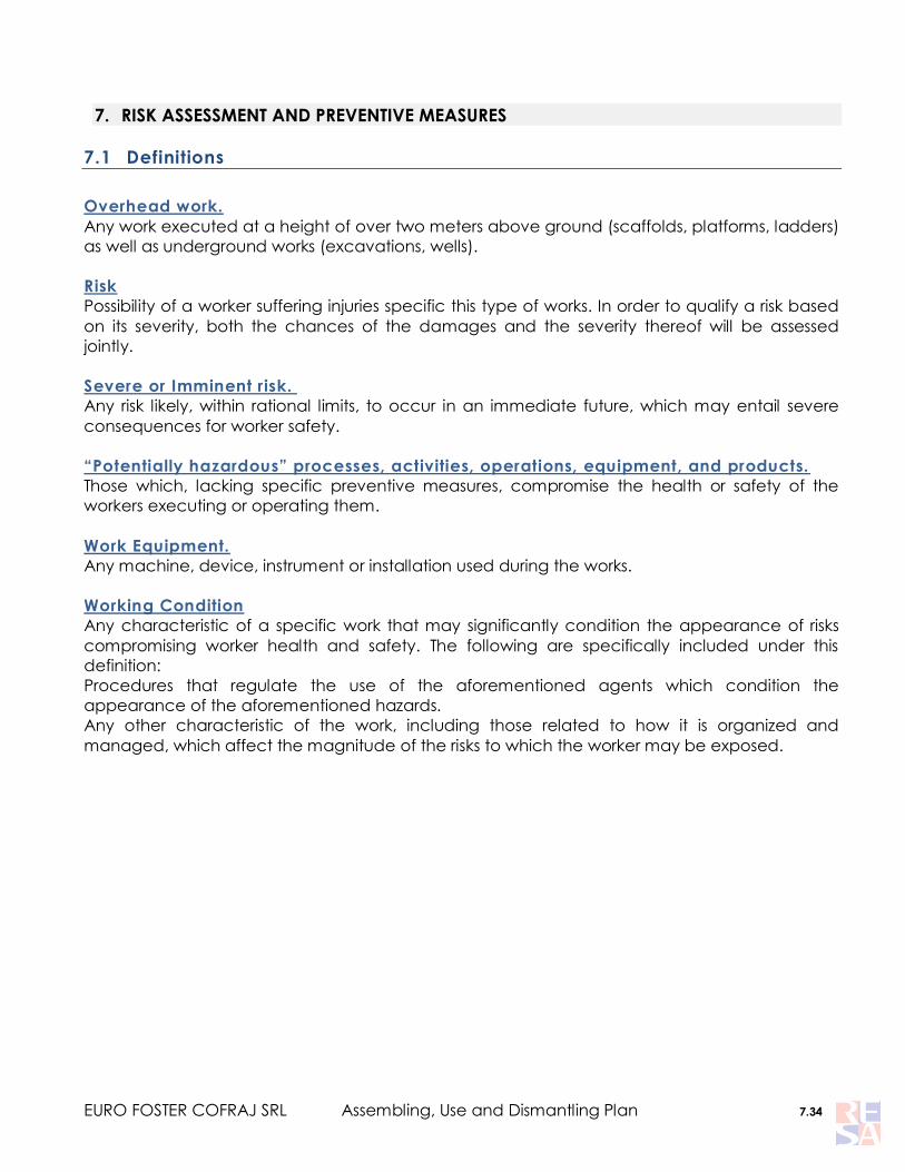
7. RISK ASSESSMENT AND PREVENTIVE MEASURES
7.1 Definitions
Overhead work.
Any work executed at a height of over two meters above ground (scaffolds, platforms, ladders)
as well as underground works (excavations, wells).
Risk
Possibility of a worker suffering injuries specific this type of works. In order to qualify a risk based
on its severity, both the chances of the damages and the severity thereof will be assessed
jointly.
Severe or Imminent risk.
Any risk likely, within rational limits, to occur in an immediate future, which may entail severe
consequences for worker safety.
“Potentially hazardous” processes, activities, operations, equipment, and products.
Those which, lacking specific preventive measures, compromise the health or safety of the
workers executing or operating them.
Work Equipment.
Any machine, device, instrument or installation used during the works.
Working Condition
Any characteristic of a specific work that may significantly condition the appearance of risks
compromising worker health and safety. The following are specifically included under this
definition:
Procedures that regulate the use of the aforementioned agents which condition the
appearance of the aforementioned hazards.
Any other characteristic of the work, including those related to how it is organized and
managed, which affect the magnitude of the risks to which the worker may be exposed.

EURO FOSTER COFRAJ SRL Assembling, Use and Dismantling Plan 7.35
7.2 General Risks
The most frequent general risks that we will find in many of the work centers, both in
industrial and construction environments are the following:
CAVITIES, DITCHES, UNPROTECTED ZONES ENTAILING FALL HAZARDS.
Our mission is to precisely fit out the corresponding group protection means, or the auxiliary
elements to ensure that works at a height, that entail daily exposure to fall risks, can be carried
out safely. For this reason, further details on the fall arrest and protection equipment that we will
need to use are provided below.
RISK OF FALLING OBJECTS DUE TO COLLAPSE OR SUBSIDENCE.
Mandatory use of safety helmet.
Never work directly over or under another workers.
Pay attention to the safety signage that indicates the risk of object.
Do not stand under loads during hoisting operations.
Do not jump over warning barriers.
RISKS OF STEPPING ON OBJECTS AND FALLING AT SAME LEVEL.
It is necessary to collaborate in order to keep work places, transit zones, ladders in orderly
fashion, clear of obstacles, removing any material or tool that may cause an accident if
stepped on.
It will be necessary to use protective footwear with a sole plate protecting against
punctures.
Mind your step, as injuries due to twisted and sprained ankles are frequent.
RISK OF FLYING FRAGMENTS OR PARTICLES.
Many times, the assembly tasks a worker may undertake are concurrent with other works
that result in projections of loose materials (welding, piece sharpening, slab cutting, etc.) ON
the other hand, the wind, material debris and dust gathered on scaffold plans also are a source
of suspended particles.
In these cases, the use of protective eyewear will be mandatory.
RISK OF ENTRAPMENT BY OR BETWEEN OBJECTS.
Before using a machine or piece of equipment it is essential to properly learn how it works,
by reading the instructions supplied by the manufacturer.
Moving elements of machines need to be totally insulated by design, as a result of the its
manufacturing process or of the location where it is placed. Otherwise, they will need to be
protected by means of covers and/or safety devices.
Maintenance, repair, lubricating and cleaning operations must be carried out once motors
and machinery equipment units are stopped. Machinery units must be equipped with devices
that guarantee safety.
EURO FOSTER COFRAJ SRL Assembling, Use and Dismantling Plan 7.36
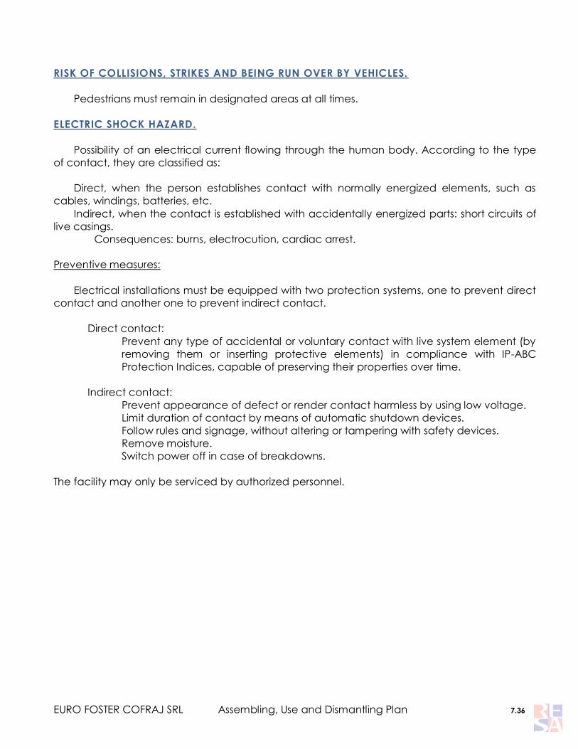
RISK OF COLLISIONS, STRIKES AND BEING RUN OVER BY VEHICLES.
Pedestrians must remain in designated areas at all times.
ELECTRIC SHOCK HAZARD.
Possibility of an electrical current flowing through the human body. According to the type
of contact, they are classified as:
Direct, when the person establishes contact with normally energized elements, such as
cables, windings, batteries, etc.
Indirect, when the contact is established with accidentally energized parts: short circuits of
live casings.
Consequences: burns, electrocution, cardiac arrest.
Preventive measures:
Electrical installations must be equipped with two protection systems, one to prevent direct
contact and another one to prevent indirect contact.
Direct contact:
Prevent any type of accidental or voluntary contact with live system element (by
removing them or inserting protective elements) in compliance with IP-ABC
Protection Indices, capable of preserving their properties over time.
Indirect contact:
Prevent appearance of defect or render contact harmless by using low voltage.
Limit duration of contact by means of automatic shutdown devices.
Follow rules and signage, without altering or tampering with safety devices.
Remove moisture.
Switch power off in case of breakdowns.
The facility may only be serviced by authorized personnel.

EURO FOSTER COFRAJ SRL Assembling, Use and Dismantling Plan 7.37
OTHER RISKS ARISING FROM WORKING IN THIRD PARTY WORKPLACES.
INDUSTRY: The wide range of third party workplaces that we may find while
assembling scaffolding structures exposes Euro Resa workers to a variety of risks, whose
preventive control requires our collaboration with clients, by complying with the SAFETY
PROCEDURES that they may have established (hot work permits, work permits, awareness of
signage and access restrictions, etc…) as well as by attending the training and instruction
sessions that will be provided to workers before accessing these centers. Thus, we can avoid
risks such as explosions, burns, electrical shock, chemical accidents, etc.
Finally, before accessing any of these centers, we will be informed of the emergency
procedures and meeting points in the event of EMERGENCIES AND EVACUATION OF SAID
LOCATIONS.
CONSTRUCTION: The occupational health and safety plan is the document or set of
documents prepared by the main contractor which can be adjusted over time, which, in
consistency with the project, and, based on a safety report or basic health and safety report
adapted to its own constructive system, allows to develop the works in adequate preventive
conditions.
As a general rule, whenever the corresponding project‟s Health and Safety Plan covers all
scaffold assembly, usage, and disassembly activities, we will comply both with said plan (as
regards work center hazards, interaction with other trades, etc…), and with the measures
contained in this assembly/disassembly plan (for specific activities).

EURO FOSTER COFRAJ SRL Assembling, Use and Dismantling Plan 7.38
7.3 Risk Related Information and Planning of Preventive Measures in Scaffold
Assembly-Disassembly Operations. Work Position: Scaffold Erector.
RIS
K
RISK DESCRIPTION Preventive or protective measures Supervisor Time frame
Id N
o. 1
.- m
ay
fro
m e
lev
atio
n
Id N
o. 3
.- S
ca
ffo
ld c
olla
pse
- Existence of multiple unprotected
gaps and stretches during the
assembly due to the nature of the
works, and mainly during worker
movements over light structures.
- Use of auxiliary worker elevation
means suspended from a crane.
- Unsecured planks and plates,
mainly
- Improper use of may arrest
systems, or lack thereof..
- Poor physical or mental
condition.
- Imprudence.
- Structure collapse due to
improper or non-existing
anchoring.
- Lack of order and cleanliness.
- Platform, plate, and structure
swaying and tipping.
- Non compliance with the
assembly plan.
It will be necessary to follow the assembly sequence
established in the Assembly Plan, in order to minimize
working during periods during which group protection is
unavailable..
Assembly
Supervision/Operators Always
Regardless of the foregoing, workers involved in the
assembly operations will need to make use of the type-
approved may arrest systems that will be supplied to
them, equipped with the adequate securing systems for
tubular structures, and shock absorbers, and to
implement the notions that will be instructed to them by
means of the appropriate instruction and training
programs and documents. The harness will be equipped
with a double clip hook for movement over light
structures. This protective measure must be specially
controlled and used assembly sequences that need to be
carried out before group protections are fitted out.
Assembly
Supervision/Operators Always
The structure of the scaffold must be firm, secured and
balanced in a way such that operator can secure himself
to it under safe conditions. The scaffold assembly
sequences have been devised taking these
considerations into account, and therefore need to be
complied with at all times.
Dirección de MOntaje Always
Workers that fail provide proof of being medically fit for
this type of tasks will be restrained from working. Likewise,
workers showing signs of any type of pathology that may
compromise their safety will be required (and will have to)
abandon their post and seek immediate medical
attention.
Assembly
Supervision/Operators Always
Operators will need to subject their IPEs, and particularly
may arrest harness and securing element, to periodical
inspections, in compliance with applicable instructions.
Direct
Supervisor/Operators Daily
Consumption of alcoholic beverages or any other type of
drug either during the working day or in the hours previous
thereto is strictly forbidden. Non fulfillment of this rule shall
be deemed as reckless behavior and will be subject to
strict sanctions.
Direct
Supervisor/Operators Always
It will be necessary to level the scaffold both horizontally
and vertically using a spirit level, in order to prevent
materials from tipping over.
Dirección de
montaje/Direct
Supervisor/Operators
Always
Planks and plates must be immediately secured against
tipping, as soon as they are fitted out.
Direct
Supervisor/Operators Always
It will be essential to keep assembly areas in proper
orderly and clean condition. Prior to the
assembly/disassembly processes, it will be necessary to
establish the points where elements will be unloaded
when they are ready to be assembled or after they are
disassembled. In no case shall they be piled in the surface
of the scaffold that is being dismantled, specially in
places where, due to the disassembly operation, group
protections are not available.
Direct
Supervisor/Operators Always
No workers shall engage in works at over 2 meters in
height without having completed a solid, sufficient,
adequate and accredited training program concerning
the occupational risks entailed by works at a height, in
compliance with the provisions set forth in the Annex of
RD 2177/2004. Likewise, operators will be trained in all
contents included in this Plan.
Jefe de Obra/Director
de montaje Always

EURO FOSTER COFRAJ SRL Assembling, Use and Dismantling Plan 7.39
RIS
K
RISK DESCRIPTION Preventive or protective measures Supervisor Time frame
Id N
o. 1
.- m
ay
fro
m e
lev
atio
n
Id N
o. 3
.- S
ca
ffo
ld c
olla
pse
- Existence of multiple
unprotected gaps and
stretches during the assembly
due to the nature of the works,
and mainly during worker
movements over light
structures..
- Use of auxiliary worker
elevation means suspended
from a crane.
- Unsecured planks and plates,
mainly
- Improper use of may arrest
systems, or lack thereof..
- Poor physical or mental
condition.
- Imprudence.
- Structure collapse or tipping
due to improper or non-existing
anchoring.
- Lack of order and cleanliness.
- Platform, plate, and structure
swaying and tipping.
- Non compliance with the
assembly plan.
All workers will restrain from engaging in imprudent
actions, will strictly comply with all preventive and
protective measures established herein. Both direct
supervisors and co-workers will be required to
immediately take appropriate action in the event of
non-compliances.
Direct
Supervisor/Operators Always
While the assembly/disassembly operations are
taking place, it will be necessary to post scaffold
usage prohibition signs in all access zones thereto.
To this regard, the red card indicating scaffold
under construction shall be fitted out as soon as the
works begin. Likewise, all scaffold accesses zones will
be signposted using warning tape.
Direct
Supervisor/Operators Always
Footwear must include antislip soles, and worker will
be responsible for making sure that it remains in such
condition at all times. It will be necessary to clean
the soles before accessing the scaffold in the
presence of puddles, or traces of mud or any other
substance which may favor slipping.
Direct
Supervisor/Operators Always
In compliance with RD 2177/04, scaffolds will need
to be inspected:
Before being placed in service.
Afterwards, periodically.
After any alteration, idle period, exposure to
weather conditions, seismic tremor, or any other
circumstance that may have affected its
resistance or stability.
Person appointed to
commissioning/Person
appointed to
inspections.
Always
Id N
o. 2
.- F
alls
at
sam
e le
ve
l.
- Lack of site order and
cleanliness.
- Scarce or insufficient
illumination
Dispose of urban waste in the designated
containers.
Do not engage in works without proper illumination.
Direct
Supervisor/Operators Always
Scaffolding materials, tools and other gear will need
to be kept in perfect condition and order at all
times.
Direct
Supervisor/Operators Always
Especially, transit zones or platforms will be kept
clear of materials.
Direct
Supervisor/Operators Always
Unloading locations shall be designated for the
materials prior to their arrival at the site.
Direct
Supervisor/Operators Always
Platforms, plates and structures shall be secured to
prevent swaying.
Direct
Supervisor/Operators Always
Proper illumination means shall be provided at all
times. Works will be suspended whenever the
minimum conditions established in Annex IV or RD
486/1997 are not met.
Client/Direct Supervisor Always
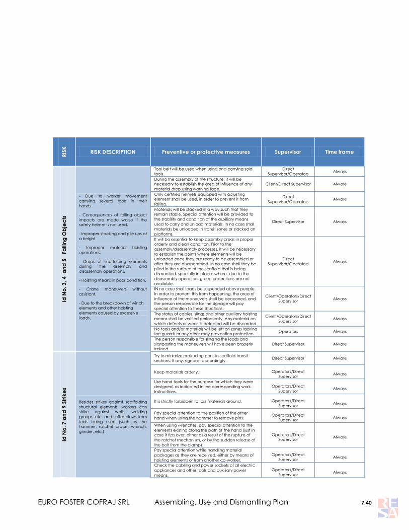
EURO FOSTER COFRAJ SRL Assembling, Use and Dismantling Plan 7.40
RIS
K
RISK DESCRIPTION Preventive or protective measures Supervisor Time frame
Id N
o. 3
, 4
a
nd
5
Fa
llin
g O
bje
cts
- Due to worker movement
carrying several tools in their
hands.
- Consequences of falling object
impacts are made worse if the
safety helmet is not used.
- Improper stacking and pile ups at
a height.
- Improper material hoisting
operations.
- Drops of scaffolding elements
during the assembly and
disassembly operations.
- Hoisting means in poor condition.
- Crane maneuvers without
assistant.
- Due to the breakdown of winch
elements and other hoisting
elements caused by excessive
loads.
Tool belt will be used when using and carrying said
tools.
Direct
Supervisor/Operators Always
During the assembly of the structure, it will be
necessary to establish the area of influence of any
material drop using warning tape.
Client/Direct Supervisor Always
Only certified helmets equipped with adjusting
element shall be used, in order to prevent it from
falling.
Direct
Supervisor/Operators Always
Materials will be stacked in a way such that they
remain stable. Special attention will be provided to
the stability and condition of the auxiliary means
used to carry and unload materials. In no case shall
materials be unloaded in transit zones or stacked on
platforms.
Direct Supervisor Always
It will be essential to keep assembly areas in proper
orderly and clean condition. Prior to the
assembly/disassembly processes, it will be necessary
to establish the points where elements will be
unloaded once they are ready to be assembled or
after they are disassembled. In no case shall they be
piled in the surface of the scaffold that is being
dismantled, specially in places where, due to the
disassembly operation, group protections are not
available.
Direct
Supervisor/Operators Always
IN no case shall loads be suspended above people.
In order to prevent this from happening, the area of
influence of the maneuvers shall be beaconed, and
the person responsible for the signage will pay
special attention to these situations.
Client/Operators/Direct
Supervisor Always
The status of cables, slings and other auxiliary hoisting
means shall be verified periodically. Any material on
which defects or wear is detected will be discarded.
Client/Operators/Direct
Supervisor Always
No tools and/or materials will be left on zones lacking
toe guards or any other may prevention protection. Operators Always
The person responsible for slinging the loads and
signposting the maneuvers will have been properly
trained.
Direct Supervisor Always
Id N
o. 7
an
d 9
Str
ike
s
Besides strikes against scaffolding
structural elements, workers can
strike against walls, welding
groups, etc. and suffer blows from
tools being used (such as the
hammer, ratchet brace, wrench,
grinder, etc.).
Try to minimize protruding parts in scaffold transit
sections. If any, signpost accordingly. Direct Supervisor Always
Keep materials orderly. Operators/Direct
Supervisor Always
Use hand tools for the purpose for which they were
designed, as indicated in the corresponding work
instructions.
Operators/Direct
Supervisor Always
It is strictly forbidden to toss materials around. Operators/Direct
Supervisor Always
Pay special attention to the position of the other
hand when using the hammer to remove pins. Operators/Direct
Supervisor Always
When using wrenches, pay special attention to the
elements existing along the path of the hand (just in
case it tips over, either as a result of the rupture of
the ratchet mechanism, or by the sudden release of
the bolt from the clamp).
Operators/Direct
Supervisor Always
Pay special attention while handling material
packages as they are received, either by means of
hoisting elements or from another co-worker.
Operators/Direct
Supervisor Always
Check the cabling and power sockets of all electric
appliances and other tools and auxiliary power
means.
Operators/Direct
Supervisor Always

EURO FOSTER COFRAJ SRL Assembling, Use and Dismantling Plan 7.41
Do not fit out braces on metallic sections that may
be in direct contact with any power source, and if
absolutely necessary, insulate the contact surface
using neoprene straps or similar elements.
Operators/Direct
Supervisor Always
The insulation of hand electrical tools will be
inspected, as well as of hoses, plugs, pins, cables,
etc. Direct Supervisor Always
Thermal, and differential relays, as well as earth
connections of all power sources used shall be
checked. Client/Direct Supervisor Always
It will be necessary to fit out signs on the work zone. Client/Direct Supervisor Always

EURO FOSTER COFRAJ SRL Assembling, Use and Dismantling Plan 7.42
RIS
K
RISK DESCRIPTION Preventive or protective
measures Supervisor Time frame
Id N
o. 1
0 F
lyin
g
fra
gm
en
ts
Flying galvanized steel fragments and material chips
caused strikes of a hammer on the scaffolding
material.
Dust, sand gathered on the materials, mainly.
Use of protective eyewear will be
mandatory during these works.
Direct
Supervisor/Operators As required
Materials must be kept in clean
condition.
Direct
Supervisor/Operators Always
Id N
o. 1
3
Ove
rstr
es
s
Postures that workers may be forced to adopt in
order to carry out a job (static and dynamic
postures).
Dorso-lumbar: Handling of loads, fundamentally while
handling scaffolding elements.
Only properly trained workers will be
allowed to carry out load handling
operations.
Assembly
manager/Direct
Supervisor
Previous
The required resting periods will be
observed, based on the intensity of
the work that is being carried out.
Direct Supervisor Always
Id N
o. 2
8 P
hy
sic
al
ag
en
ts: n
ois
e
Strikes with hammer for the assembly of structures.
Metal to metal strikes during material unloading and
stacking procedures.
Noises generated by the equipment present in the
site where the works are being carried out.
Do not throw or toss metal elements
abruptly.
Direct
Supervisor/Operators Always
Whenever necessary, use hearing
protection, such as earplugs or
earmuffs.
Direct
Supervisor/Operators As required
Proceed to prevent noise at its
source, by establishing the
mechanisms required to insulate the
noise generating source, whenever
possible.
Client/direct
supervisor/operators As required

EURO FOSTER COFRAJ SRL Assembling, Use and Dismantling Plan 7.43
7.4 Individual Protection Equipment.
DESCRIPTION OF MANDATORY IPES DURING SCAFFOLDING WORKS
HELMET UNE-EN 397 IPE CATEGORY: II
The purpose of the helmet is to protect head and ears, absorbing the
maximum amount of energy when receiving the impact from a falling object or
striking against any obstacle, and bending or even breaking depending on the
impact it receives. It provides an air chamber that provides a cushioning effect
in the event of an impact.
Points that need to be taken into account:
a) It will be necessary to use a chin strap or any other head adjusting mechanism to
prevent the helmet detachment due to a fall.
b) The helmet is manufactured in a single size, and can be adjusted to different sizes.
c) After a severe impact, the helmet will need to be disposed of, as it may have internal
fractures that cannot be appreciated at sight, hindering its protective capacity.
d) Do not apply paints nor adhesive products.
e) It will be washed using water and neutral soap, and left to dry out in a shady and fresh
place.
FALL ARREST HARNESS UNE-EN 361 IPE CATEGORY: III
The fall arrest harness is an individual protective
equipment that comprises several flexible flat tape straps
(generally nylon) that distributes the different stress it bears
during its use throughout the body. It has been designed to
allow the operator to carry out his works at a height without
hindering his movement capacity, and to prevent possible
falls. The connection between the harness and other
elements is provided by means of a series of rings. The
harness is a body prehension device intended to prevent
and stop falls, and needs to be capable of slowing down
and stopping a worker while he/she is falling.
The fall arrest system must be tied to the harness hooking element, in a way such that it is
placed slightly above the body‟s center of gravity, approximately at the height of the sternum,
on both shoulders, and/or the back of the user, in compliance with EN-UNE-361. Its purposes in
the event a user falls are the following:
Distribute forces caused by the falling motion throughout the body of the fall prevention
harness user‟s body, with optimum guarantees and safety conditions for the worker.
To stop a fall along with the remaining components of the fall arrest system.

EURO FOSTER COFRAJ SRL Assembling, Use and Dismantling Plan 7.44
Important points that need to be taken into account:
The adjustments must not be fitted too tightly, to prevent blood transit issues; nor
excessively loose.
An unconscious person‟s life may be in danger if he/she spends more than 10 minutes
hanging. Complete mobility, associated to prehension of the straps on the body can
result in severe circulatory and respirator consequences for a persons body.
It is strictly forbidden to attach any type of fall arrest device to the ventral rings of the
harness. The only purpose of these rings is to keep the positioning rope in place.
Use instructions:
1. Hold the harness from the plate on the “dorsal” ring. It must rest at the height of the
shoulder blades.
2. Insert the legs through the straps that hold the thighs of the legs.
3. Close and adjust the fastening belt to the waist.
4. Insert the arms through the shoulder straps of the harness without from the straps and
adjust them by pulling from the free ends.
5. Close and adjust the chest strap (if necessary).
6. Adjust thigh straps to legs using female buckles.
7. The fall arrest system must be attached to the harness hooking elements, in a way such
that it remains above the body‟s center of gravity, approximately in front of the sternum
(chest ring), in both shoulders, or in the back of the user (dorsal ring).
Inspections and maintenance.
The lifespan of a harness is 5 years, although the mechanical wear, along with the
frequency and use conditions can reduce it. In any case, each manufacturer will
establish the maximum use in the corresponding instructions.
Before and after any use, harness condition will be verified: strap and seam stitching,
wear or corrosion in metallic pieces, lack of alterations that may cause severe damage
in case of falls.
Keep harness away from cutting edges, and chemical agents.
Do not expose to sunlight unnecessarily. After use, keep in its corresponding bag.
Clean using water and neutral soap, and set to dry out in a shady and fresh place.
Any harness involved in a fall, which presents anomalies or which requires some type of
repair will need to be removed preventively from service and will be inspected by
authorized personnel before using it again.
ANCHORING LANYARD UNE EN 354-355 IPE CATEGORY: III
The lanyard is an element whose purpose is to connect the worker by
means of the fall arrest ring of the harness to a structure or place of
work. This allows autonomous movement through structures lacking
specific safety elements or the conduction of works beyond the reach
of the lifeline.
The basic elements that make up an anchoring lanyard are:

EURO FOSTER COFRAJ SRL Assembling, Use and Dismantling Plan 7.45
Rope, flat strap or similar element. The anchoring lanyard will have a resistance to
rupture equal or above 18kN.
A clip hook with a lock that connects the lanyard to the harness ring.
Connector at the end of the anchoring lanyard for the connection to a work structure or
device.
Energy absorber.
The following points need to be taken into account:
It will be necessary to place the center of gravity (belly) above the anchoring point in
order to prevent any risk situation with a fall to a different level with a factor above 1.
It is essential to attach an energy absorption system to this element.
The anchoring lanyard can be simple or double, offering the possibility to use one or two
anchoring points. The first case is recommended for use when securing the harness using the
dorsal ring, while the double anchoring lanyard provides a greater level of polyvalence and
comfort in the case the user falls, anchored to the sternum ring.
It is essential to attach an energy absorption system to these elements, even during secured
works. Currently, almost all commercial harness manufacturers include the absorber directly on
the anchoring lanyard, thus eliminating a number of connectors in some of their models.
CONNECTORS UNE-EN 362 IPE CATEGORY: III
These are metal rings with an automatic blocking opening/closing
mechanism. We can find two types: CLIP HOOK AND LARGE
LOCKING TIE HOOKS They sport the same type of locking device
which requires two voluntary manual and consecutive actions at
least. The static resistance without tear or rupture, along its
longitudinal axis, will be above 15 KN.
They connect an IPE (lanyards, harness, absorber, etc.) to the remaining safety chain. They can
be made of steel or of any light alloy.
Clip Hooks
Clip hooks are designed to bear loads in longitudinal direction, along the main axis. Likewise,
a clip hook will offer its greater resistance with the locking clip in resting position, that is,
perfectly latched. It is essential, when performing daily works, that the resistance of a clip hook
with its clip open or bearing a transversal load to remain above 60%.
Only clip hooks with safety clip will be used to guarantee worker safety.
Large Locking Tie Hooks
They offer the advantage of being over dimensioned, with
openings that range between 2.1 and 10 cm. They can be used
with one hand only, allowing quick and safe movement along the

EURO FOSTER COFRAJ SRL Assembling, Use and Dismantling Plan 7.46
structure of the scaffold. It is essential to use them in combination with an anchoring lanyard,
comprising a fall arrest system that is compliant with the specifications provided below.
GLOVES UNE-EN 420 AND 388 IPE CATEGORY: II
They are necessary in almost all work operations and conditions, to
protect workers from either from cold weather, and especially, from
mechanical risks, such as small cuts, scratches, rash, etc.
SAFETY FOOTWEAR UNE-EN 345 IPE CATEGORY: II
The footwear has to include non-slip soles; it will be necessary to
take into account tasks being carried out at low temperatures. They
also provide protection against metal and acid, splashes. It will need
to be waterproof, with protective toe (200Kjoule), made of synthetic
material rather than metallic material, cushioned, with antistatic,
antislip and/or leather sole, and a synthetic or steel protection insole
with polyurethane exterior.
FALL ARREST SYSTEMS
This system is comprised by a set of elevation fall arrest IPEs intended to prevent and stop any
fall with optimum guarantees, and safety conditions. It is made up by several elements:
FALL ARREST
HARNESS
+
Described in the foregoing points (7.3.1)
FALL ARREST
DEVICE
+
Is a subsystem that is responsible for automatically
blocking any eventual fall affecting the user.
ANCHORING
ELEMENTS
+
These can be synthetic fiber ropes, straps, or bands,
metallic cables or chains, depending on the specific
requirements foe achieve fall arrest device.

EURO FOSTER COFRAJ SRL Assembling, Use and Dismantling Plan 7.47
ENERGY
ABSORBER
+
This system is comprised by a band, sewn with weak
stitches that give up at a certain level of load,
favoring a dynamic braking by absorbing a great
amount o the shock force generated during a fall.
The absorber must not stretch under static loads
below 2 KN (200 KP). The Maximum Braking Force will
not exceed 6 KN and the braking distance (H) must
not exceed 5.75 meters. Therefore, it will be
necessary to take into account the anchoring point
and to provide a 6m clearance under the operator
to prevent him/her from hitting the ground or
suffering lateral impact.
CONNECTOR(S)
+ Described in the foregoing points (7.3.1)
ANCHORING
POINT
Is the point where the fall arrest device can be
assembled or disassembled.
The most appropriate fall-arrest systems for scaffolding works are:
ANCHORING ELEMENT WITH ENERGY ABSORBER
This system will allow us to move freely and safely throughout the structure, in zones located
far away from the protection system. A double lanyard with energy absorber will be used.
Before any use it will be necessary to verify the following:
1. Proper closure of connector hooks and lack of bending and corrosion in metal elements.
2. That slings do not show signs of rupture , and that all wear indicator patches are in
perfect condition. They will be subject to visual control, detecting cuts, worn out or burnt
zones.
3. The energy absorber‟s rupture plastic is still in place and no cracks or alterations can be
detected on it.
4. The harness will also be inspected, following the previous instructions.

EURO FOSTER COFRAJ SRL Assembling, Use and Dismantling Plan 7.48
Anchoring points in the scaffold structure:
First of all, it is mandatory to put group safety before individual safety: observe all assembly
instructions, which entails that for a proper assembly of the scaffold, before accessing the
following level of the structure, it will be necessary to fully complete the lower level, in a way
such that it is possible to access the upper level using the corresponding embedded ladder.
Movement and works on light structures (without plates or protections) must be limited to
essential tasks and always using fall arrest systems in the terms described below.
On the other hand, it is essential to verify, before using the structure as anchoring point, the
bracing of the structure to the nearest wall in compliance with the provisions set forth in the
assembly plan. It will be necessary to use, as anchoring element of the selected fall arrest
system, one or two hooks compliant with tubular structures, with sufficient diameter and
resistance and an automatic closing mechanism. For a proper use of the hook, IT IS ESSENTIAL to
have the structure properly braced in order to render it capable of bearing, if necessary, the
impact resulting from the fall of an operator.
Scaffold anchor points. Before anchoring the harness to the structure, it will be necessary to
make sure that the piece has been properly assembled, and that lower levels are completely
assembled. Once the scaffold is stabilized by means of the aforementioned bracing, it will be
possible to secure the hook of the harness to the rosette of the standards, the frames (R70), or
the internal guardrails (never in diagonal braces nor toe guards).
FALL ARREST DEVICE WITH FLEXIBLE ANCHOR LINE.
This device which is regulated by UNE-EN 351-2 consists of an anchoring
line which can be made with synthetic ropes (polyamide) or a galvanized
steel cable which, just as the previous one, serves acts as the guide for the
fall arrest device, which travels freely along the vertical. The fall arrest
device causes the fall to stop by friction after being subject to a sudden
downwards thrust.
System Components:
Specific Safety Rules:

EURO FOSTER COFRAJ SRL Assembling, Use and Dismantling Plan 7.49
It must be fixed to an upper anchoring point, and must be equipped with an end buffer
in a way such that the fall arrest system DOES NOT is not accidentally removed from the
anchoring line.
If the guided type fall arrest device is equipped with a manual blocking system, the
lower end of the line must be secured by means of a lower fixed manufactured endpoint
or by means of a ballast, to facilitate its operation.
The anchoring line will be designed in a way such that it only allows the fall arrest device
to move in the specified directions.
It will be possible to incorporate an energy dissipation element to the guided type fall
arrest device, to the anchoring element, or to its anchoring point.
FALL ARREST DEVICE WITH RETRACTILE DEVICE.
This device is equipped with a retractable mechanism, with an anchoring element that can
be a lanyard, a galvanized steel cable, or synthetic fiber band, with characteristics equivalent
to those of polyamide or polyester fibers.
The anchoring element is wound up around a drum and moves freely upwards and downwards
at normal speed, although always subject to a slight retracting motion, or in other words, the
anchoring element unwinds from the drum when subjected to a light load, and winds up
automatically when that load ceases to be exerted. Any fall or sudden movement activates a
blocking mechanism which results from the centripetal force which the buffers located inside
the drum are subject to. Its mechanism works just as the one present in vehicle seat belts.
Load usage and limits must be adjusted to the provisions established in the usage instructions.
TEMPORARY HORIZONTAL LIFELINES
These lifelines act more as an anchoring device rather than as a fall arrest system. Either
rope or straps can be used in order to configure it. The rope or the strap needs to be tightened
to a certain extent to render proper functionality. This point will be reached by following
manufacturer instructions, and will depend on the device used.
VERY IMPORTANT: It is completely forbidden to improvise horizontal lifeline installations
using ropes or cable tightened by “guesstimating”, using some type of “block and
tackle” or reducing gear system.

EURO FOSTER COFRAJ SRL Assembling, Use and Dismantling Plan 7.50
7.5 Signpostings
The signs posted on the Grupo Resa installations and machinery will comply with the
provisions of Royal Decree 485/1997.
PANEL SIGNS
WARNING SIGNS
Description:
Triangular shape.
Black pictogram over yellow background (the yellow color must cover at least 50% of
the sign‟s surface) with black borders.
As an exception, the background color of the “hazardous or irritant materials” will be
orange, instead of yellow, in order to avoid confusion with other signage used for
regulating road traffic.
Flammable
materials
Explosive
materials
Toxic materials Corrosive
substances
Hazardous or irritant
materials
Handling Vehicles Electric shock
hazard
Danger in general Suspended loads Oxidizing
substances
Non-ionizing
radiations
Laser radiations Risk of tripping Falls from elevation

EURO FOSTER COFRAJ SRL Assembling, Use and Dismantling Plan 7.51
PROHIBITION SIGNS
Description:
Round shape.
Black pictogram over white background, red borders and band (transversal descending
from let to right crossing the pictogram at a 45º angle with respect to the horizontal). The
red color must cover at least 35% of the signs surface.
No smoking No smoking or
naked flame No pedestrians
Do not put out
with water
No unauthorized
access Not drinking water
No handling
vehicles Do not touch
OBLIGATION SIGNS
Description:
Round shape.
White pictogram over blue background (the blue color must cover at least 50% of the
sign‟s surface).
Eye
protection
must be worn
Safety helmet
must be worn
Ear protection
must be worn
Respiratory
equipment
must be worn
Safety boots
must be worn
Safety gloves
must be worn
Safety overalls
must be worn
Face
protection must
be worn

EURO FOSTER COFRAJ SRL Assembling, Use and Dismantling Plan 7.52
Safety harness must
be worn
Pedestrians must use
this route
General
mandatory sign
(must be
accompanied by
another sign)
SIGNAGE RELATED TO FIRE FIGHTING EQUIPMENT
Description:
Rectangular or square shape.
White pictogram over red background (the red color must cover at least 50% of the
sign‟s surface).
Fire hose Fire ladder Fire
extinguish
er
Fire Telephone
Direction that must be followed (sign providing additional information)
FIRST AID AND SAFETY SIGNS
Description:
Rectangular or square shape.
White pictogram over green background (the green color must cover at least 50 of the
sign‟s surface).
First aid Stretcher/trolley Emergency shower Eye rinse
Emergency exit / route
Direction that must be followed (sign providing additional information)

EURO FOSTER COFRAJ SRL Assembling, Use and Dismantling Plan 7.53
COMPLEMENTARY SIGNS FOR PERMANENT RISK
Used in the following cases:
To warn about slopes, obstacles or any other element that results in tripping, falls,
collisions, or striking hazards it will be possible to choose, if the same level of efficiency is
guaranteed, by the corresponding panel in compliance with the provisions set forth in
the foregoing section, or by a safety color. Another option is to use both
complementarily.
The zones within work premises that worker is allowed to access in order to carry out any
related duty, that entail people falling, object falling, collisions or strike hazards will be
marked using a safety color.
The preferred signage in the two aforementioned sections will be provided by means of alternating
yellow and black stripes. The stripes must have an approximate inclination of 45º, and have similar
dimensions to the ones provided in the following model:
SIGNPOSTING AND TAGGING HAZARDOUS SUBSTANCES
Container carrying hazardous substances will be tagged in a clear, legible and indelible
manner, in the official language of the State.
The size of the tag must correspond at least to the dimensions described in Table II and
will need to be placed in a visible spot, never on locks , seals or any other component
that is usually removed to open the container.
Tags must be readable horizontally when the container is standing in upright position.
Indications such as “non toxic”, “not hazardous” or any other analogous indication will
not be allowed to appear in the tag or on the container of any one of the substances
included in the corresponding regulations.
The text in the tag must include:
Name of the substance in compliance with the listing included in the aforementioned
Royal Decree, or, if the substance is not included, the IUPAC nomenclature, preferably.
Common name, when appropriate.
Substance concentration, where appropriate.
Name and address of the individual or corporation manufacturing, bottling, marketing or
importing the hazardous substance.
Hazard pictograms and indications, as described in Table III. A maximum of two
pictograms shall be included, each one of which must at least occupy one tenth of the
surfaces indicated in Table II.

EURO FOSTER COFRAJ SRL Assembling, Use and Dismantling Plan 7.54
Explosive
substance
Oxidizing substance Easily flammable Corrosive substance
Irritant substance Harmful substance Toxic substance Very toxic substance
GESTURE SIGNS
Used as command code for machinery, cranes… The color of the vest can be green, orange or
red…
Start
(attention)
Danger (stop)
EURO FOSTER COFRAJ SRL Assembling, Use and Dismantling Plan 8.55
8. DRAWINGS
In general terms, they will correspond to location drawings, drawings of the scaffolding that is to
be assembled, detail drawings, drawings of pertinent facilities or structures, etc.
The Drawings corresponding to the Assembly of the Scaffold are appended below.
List of Drawings:
Drawing No. Name Rev. Notes
1
2
3

EURO FOSTER COFRAJ SRL Assembling, Use and Dismantling Plan 9.56
9. TECHNICAL DATA OF THE MANUFACTURER
Grupo Resa is an international business corporation consisting of 15 companies specializing in
the design, engineering, manufacturing, and installation of tubular and motor-driven
scaffolding solutions.
Grupo Resa has an Engineering and Development department committed to the improvement
of our products and the development of innovations, in order to turn our scaffolds into efficient
and safe means from which conduct works at a height, in compliance with the level of
responsibility and importance of the projects we engage in.
Currently, Grupo Resa has created one of the most competitive companies in the industry,
thanks to its extreme technological level, and its organizational development in risk prevention,
and occupational health and safety, as well as to the position it currently holds both in the
domestic and international markets.
Grupo Resa‟s manufacturing, storage, and distribution plants comprise what is one of Spain‟s
largest infrastructures, which guarantees the level of flexibility required to tackle from the smaller
to the largest projects.
In different application sectors such as Construction, Restorations, Industry (Petrochemical,
Thermal Generation, Nuclear Energy, Cement production, General…), the Naval Sector, Civil
Works
Always keeping in mind the Company‟s priority objective: To provide the best Service.
9.1 Resablock multidirectional scaffolding system.
Product Certified in compliance with UNE-EN 12810 / UNE-EN 12811
Reference: Resablok Handbook.
Certifications. Components.
Technical applications. Technical data sheets.
Assemblies. Industries.
etc.
9.2 Manufacturer
Multidirectional scaffolding system RESABLOK.
Manufactured by: Resa Quality Factory, S.L.
Area Empresarial Andalucía, Sector 1.
C/ Serranía de Ronda, 6-8
28320 Pinto – MADRID

EURO FOSTER COFRAJ SRL Assembling, Use and Dismantling Plan 10.57
10. ANNEXES
Documentation related with the assembly, usage, and disassembly of the scaffold, not
included in previous sections.
These may be:
- External fall arrest harness certificates
- Life line characteristics.
- Hoisting element characteristics.
- Anchoring element properties
- Mesh properties.
- …
- Reference data.
- …
- Contact information, Medical services, etc.
- …