scalable floating-point matrix inversion design using ... · pdf filetheory of operation...
TRANSCRIPT

SummaryMatrix inversion is widely used in numerous signal processing and data analysis algorithms. Many of these algorithms use a floating-point data format to accommodate large dynamic ranges of the random matrices (see Adaptive Beamforming for Radar: Floating-Point QRD+WBS in an FPGA (WP452) [Ref 1]). This application note focuses on the design of a scalable matrix inversion function using the Vivado® High-Level Synthesis (HLS) tool, which takes the source code in C programming language and generates highly efficient synthesizable Verilog or VHDL code for the FPGA. The size of the matrix is defined in the C header file and can be easily changed. The example design employs a pipelined architecture to achieve high throughput for per-user based massive multiple-input, multiple-output (MIMO) wireless communication systems.
Download the reference design files for this application note from the Xilinx® website. For detailed information about the design files, see Reference Design.
IntroductionMatrix representation of large-scale systems is a powerful tool to reveal the mathematical relationship among a large number of variables. Consider a multiple-input, multiple-output (MIMO) wireless system where the numbers of transmit and receive antennas are M and N, respectively. Denote the transmit signals on the antennas as X=[x0, x1, x2, … xM-1]T, the received signal as Y=[y0, y1, y2, … yN-1]T, and ignore the noise. The simplified communication system can be written as:
Y = H X
where H is the channel matrix whose elements {hi,j} describe the changes in phases and magnitudes for the radio signal that propagates from the ith transmit to the jth receive antennas. On the receiver side, assuming perfect knowledge about H has been acquired from the training symbols, the transmit signal can be computed from the observed receive signal Y as:
X' = inv(HHH) HHY
where HH is the transpose and conjugate operation on the matrix H and inv(A) is the inverse of the square matrix A= HHH that satisfies
inv(A) A = I
and I is an N-by-N identity matrix.
Application Note: UltraScale and UltraScale+ Families
XAPP1317 (v1.0) October 2, 2017
Scalable Floating-Point Matrix Inversion Design Using Vivado High-Level SynthesisAuthor: Matt Ruan
XAPP1317 (v1.0) October 2, 2017 www.xilinx.com 1

Theory of Operation
This mathematical model is applicable to many other systems where matrix inversion is required to solve the unknowns of the generic equation. When the elements of the matrix to be inversed are time-varying complex variables that change in a large range, floating-point representation of the data and calculation results are often more desirable than fixed-point for higher numerical stability and precision. Unfortunately, floating-point support in hardware description language (HDL) is quite limited at the moment and coding algorithms in floating-point is much more complicated than in fixed-point.
This application note explains how to design a floating-point matrix inversion module in the C programing language, and then use the Vivado HLS tool (see Vivado Design Suite User Guide: High-Level Synthesis (UG902) [Ref 2]) to synthesize it into HDL for implementation on programmable logic devices. Vivado HLS is able to generate high-performance pipelined architecture according to the given constraints, and create test benches to ensure the behaviors of HDL and C code are identical. In many cases, the Vivado HLS synthesized code has similar efficiency and performance to that of hand-coded HDL design by an experienced logic engineer.
Theory of OperationThere are many methods to compute the inverse of a matrix. In this application note, the LU decomposition algorithm is selected for hardware implementation, which consists of three steps: decomposition, inversion, and multiplication, as shown in Figure 1.
The first step is decomposition. For any given full-rank matrix A, it is possible to compute a row permutation matrix P, a lower-triangle matrix L, a diagonal matrix D, and an upper-triangle matrix U such that:
P A = L D U
The diagonal elements of L and U are all 1s. It suffices to find one solution of such decomposition for the purpose of matrix inversion, while the solution is not necessarily unique.
Next, the inversion of the matrices P, L, D, and U can be performed by taking advantage of the special matrix structures:
• P is a row-permutation matrix, and the inversion is a column-wise permutation.• D is a diagonal matrix so the inverse remains diagonal.• U and L are triangular matrices, and the inverse can be computed in an iterative manner as
shown in Figure 2. Suppose {ai,j} of the lower-triangular matrix on the left-hand side are
X-Ref Target - Figure 1
Figure 1: Three Steps of Matrix Inversion
Matrix LUP Decomposition
LUP Matrix Inversion
Inverse Matrix Multiplication
A {P, L, D, U} {P-1, L-1, D-1, U-1 } B = inv(A)
X19205-062217
XAPP1317 (v1.0) October 2, 2017 www.xilinx.com 2

Pipelined Matrix Inversion Architecture
known, then the elements of the inverse matrix {bi,j} on the right-hand side can be computed in three iterations.
In the third and last step, the inverses of U, D, L and P are multiplied together to obtain the final output, A-1.
A-1 = U-1 D-1 L-1 P-1
The special matrix structures of the inverse matrices lead to much reduced complexity:
• The multiplication with P-1 is a column-wise permutation.• D-1 is a diagonal matrix so the multiplication with U-1 can be decomposed into a series of
scalars dot multiply with column vectors.• The multiplication of one upper triangular and one lower triangular matrix can be reduced
to a lower-order matrix multiplication and performed in an iterative manner as shown in Figure 3.
Pipelined Matrix Inversion ArchitectureThe matrix inversion module is pipelined at different levels for high throughput. At the sub-system level, the matrix inversion module consists of three functional blocks responsible for matrix decomposition, inversion, and multiplication, respectively. Ping-pong memory is inserted between the blocks to parallelize the functions.
The matrix operations within each of the functional blocks are vectorized to facilitate a pipelined multiply-and-accumulate architecture. This is important for matrices in floating-point format because every addition of two floating-point numbers needs to go through decimal
X-Ref Target - Figure 2
Figure 2: An Example of Lower-Triangular Matrix Inversion
110
a 2, 1
a 3, 1 a 3, 2
a 4, 1 a 4, 2
01a 4, 3
0
01
00 1
10
b2, 1
b3, 1 b3, 2
b4, 1 b4, 2
01b4, 3
0
01
00 1
10
01
0
01
00
= 00 0
000
110
a2, 1
a3, 1
a 4, 1
1 01
00
b2, 1+a3, 2+ b2, 1 b3, 1+a4, 2+ b2, 1 a4, 3+ b3, 1 b4, 1+
a3, 2 b3, 2+a4, 2 a4, 3+ b3, 2 b4, 2+
0
a4, 3+b4, 3
0=
Iteration 1: b2, 1 a2, 1= - b3, 2 = -a3, 2 b4, 3= -a4, 3
Iteration 2: b3, 1 a3, 1= - -a3, 2b2, 1
Iteration 3: 4, 1 a4, 1= - - a4, 2b2, 1b -a4, 3b3, 1
b4, 2 a4, 2= - -a4, 3b3, 2
X19208-050317
X-Ref Target - Figure 3
Figure 3: Iterative Matrix Multiplication
x
0(n-1) x 1
=G
u
(n-1) x (n-1)
1 x (n-1)y 0
(n-1) x 1 Hv (n-1) x (n-1)
1 x (n-1) x y + u v u H
G HvGTo be computed in the next iteration
X19216-062217
XAPP1317 (v1.0) October 2, 2017 www.xilinx.com 3

Pipelined Matrix Inversion Architecture
point alignment, addition, rounding and exponent normalization steps, which typically take more than five clock cycles. For example, to implement (c=a1b1 + a2b2 + a3b3), if a and b are all fixed-point numbers, then the multiply and accumulate can be implemented on one DSP in a pipelined manner as shown in Figure 4. However, if a and b are all floating-point numbers, then idle clock cycles have to be inserted before the second addition which leads to a significant degradation in efficiency.
The strategy to work around the problem is to define an intermediate variable (d = a1b1 + a2b2) and vectorize the operations. More specifically, instead of calculating one individual c or d, it always calculates a vector of both:
d1 = a1,1 b1,1 + a1,2 b1,2d2 = a2,1 b2,1 + a2,2 b2,2d3 = a3,1 b3,1 + a3,2 b3,2
…c1 = d1 + a1,3 b1,3c2 = d2 + a2,3 b2,3c3 = d3 + a3,3 b3,3
…
After the equation transformation, the floating point multiply-and-addition operations can be implemented in a pipelined architecture as shown in Figure 5.
X-Ref Target - Figure 4XXXX
Figure 4: Comparison Between Fixed-Point and Floating-Point Multiply-and-Add Operations
X
a
b +
a1 2
a a 3
b 1 2b b 3
c
c
Fixed-point Data
a1 2
a a 3
b 1 2b b 3
c
Floating-point Data
X19217-062217
XAPP1317 (v1.0) October 2, 2017 www.xilinx.com 4

Pipelined Matrix Inversion Architecture
This strategy is applicable to all three matrix inversion steps. For the first, as illustrated in Figure 6, the LU decomposition is performed in an iterative manner such that in every iteration the decomposition of an N-by-N matrix A is reduced to that of an (N-1)-by-(N-1) matrix. The reciprocal of a only needs to be computed once and then the scalar is multiplied to the row and column vectors u and l, respectively. The vector multiplication of u and l needs (N-1)2 scalar multiplications before being subtracted from A. The number of floating-point additions in each computation step is limited to one to avoid idle clock cycles.
For the second matrix inversion step, the lower and upper triangular matrix inversion can be converted into a series of column/row operations. Figure 7 illustrates the computation of the first column of the inverse matrix [b2,1, b3,1, b4,1]T in the example shown in Figure 2. Because every equation only contains one multiplication and addition, they can be computed in a pipelined manner.
X-Ref Target - Figure 5XX
Figure 5: Pipelined Architecture for Vectorized Floating-Point Multiply-and-Add Operations
X
a
b +
d
a1,1
b
+ cX
a
b
X
a
b
n,1
n,1
n,2
n,2
n,3
n,3
n
n
1,1
a1,2
b1,2
a2,1
b2,1
a2,2
b2,2
3,1
b3,1
a3,2
b3,2
a
d1 d2 d3
a1,3
b1,3
a2,3
b2,3
3,3
b3,3
a
c1 c2 c3
X19218-050317
X-Ref Target - Figure 6
Figure 6: Iterative Update for LU Decomposition
a
0(n-1) x 1
I(n-1) x (n-1)
1 x (n-1)1 0
(n-1) x 1 Ll (n-1) x (n-1)
1 x (n-1)=
a
(n-1) x 1 A
u
(n-1) x (n-1)
1 x (n-1)
-1l a
L(n-1) x (n-1) U(n-1) x (n-1)= A (n-1) x (n-1) -
(n-1) x 1l-1a u1 x (n-1)
1
0(n-1) x 1 U
u
(n-1) x (n-1)
1 x (n-1)a-10
X19219-062217
XAPP1317 (v1.0) October 2, 2017 www.xilinx.com 5

Implementation Details
For the third matrix inversion step (see Figure 8), the multiplication of two triangular matrices can be realized by an iterative approach such that the matrix multiplication is decomposed into a number of vector multiplications without interdependency.
These vectorization methods are much easier to describe in C programing language rather than in HDL. The Xilinx Vivado HLS tool is able to synthesize the C code into HDL and implement it on the FPGA.
Implementation DetailsThe performance of the matrix inversion function needs to be validated carefully to ensure that the numerical errors are within an acceptable range. The inv() function in MATLAB is taken as the golden reference for comparison with the C implementation. Then, the same C source code is synthesized into RTL by Vivado HLS. Because both the RTL and MATLAB C MEX function come from the same C source code, they should bit-true match each other and have the same performance. The workflow diagram shown in Figure 9 illustrates the steps of HLS development from MATLAB. The approach is quite generic and applicable to many use scenarios besides matrix inversion.
X-Ref Target - Figure 7
Figure 7: Column-wise Iterative Update for Triangular Matrix Inverse
X-Ref Target - Figure 8
Figure 8: Iterative Update for Matrix Multiplication
1a2, 1
a3, 1
a4, 1
0
1
0
0
b2, 1+a3, 2+ b2, 1 b3, 1+a4, 2+ b2, 1 a4, 3+ b3, 1 b4, 1+
a2, 1
a3, 1
a4, 1
---
- a3, 2 s1
- a4, 2 a4, 3s2-
= b2, 1
= b3, 1
= b4, 1
=
s1
s=
2
s3
==
s2
s3
== s1 s3=
s2
s2 s3
X19221-050517
1 0
(n-1) x 1 Ll (n-1) x (n-1)
1 x (n-1)a
0(n-1) x 1 U
u
(n-1) x (n-1)
1 x (n-1)
=La +
Uull
u
LUTo be computed inthe next iteration
X19215-062217
XAPP1317 (v1.0) October 2, 2017 www.xilinx.com 6

Implementation Details
A performance metric needs to be defined for the performance validation step. For matrix inversion function, the squared root of the mean square error of the matrix elements is selected as the performance metric. More specifically, denote {ak,j} as the matrix inversion result, {gk,j} as the golden reference, then the performance metric is given by Equation 1.
Equation 1
X-Ref Target - Figure 9
Figure 9: Vivado HLS Workflow (from MATLAB to RTL)
Matlab Algorithm C Algorithm Synthesizable C
Matlab Performance
Validation
Mex Wrapper
PerformanceReport
Report
RTL Design
Vivado HLS Directives
Vivado IDE
BER
SNR
MatlabC AlgorithmSynthesizable C
X19222-062217
Err ΣkΣ j ak j, gk j,– 2
ΣkΣ j gk j,2--------------------------------------------=
XAPP1317 (v1.0) October 2, 2017 www.xilinx.com 7

Implementation Details
The following MATLAB script is used for matrix inversion performance evaluation.
% Start testingfor k=1:N_test,
% generate a random matrix within N_rngx = complex((1-2*rand(NL, NL))*N_Rng, (1-2*rand(NL, NL))*N_Rng);
% call DUT, the C implementation compiled into a mex function[y, stat] = luinv_mx(x);
% call Matlab inv function as the golden referencegold = inv(x);
% compare the output of DUT and golden referencediff = abs(gold-y).^2;diffsum(k) = sqrt(sum(sum(diff))./sum(sum(abs(gold).^2)));
end
Here luinv_mx(x) is the matrix inversion MEX function compiled from the C source code synthesizable by Vivado HLS. The array diffsum saves the performance metric. When N_test is sufficiently large, a histogram of the numerical errors can be analyzed to determine the performance of the matrix inversion implementation. For 32x32 matrices, N_test=10000 random matrices are tested in MATLAB and in a few minutes, a histogram of the errors is obtained as follows. The simulation of the same amount of data in RTL can take days, if not weeks, to complete.
>> gettv_luinvMean Errors (N=10000) MSE = 2.138889e-06, Max = 2.127699e-04
The histogram shown in Figure 10 illustrates that the performance of the matrix inversion function is satisfactory and that most results have very small errors close to zero. Occasionally, some results have larger errors but are still within 0.02% of the data magnitude.X-Ref Target - Figure 10
Figure 10: Histogram of Errors for 10,000 Complex Random Matrices of 32x32 in SizeX19214-050317
XAPP1317 (v1.0) October 2, 2017 www.xilinx.com 8

Implementation Details
The main C function looks like the following:
char luinv(cfloat_t A[NL][NL], cfloat_t Ainv[NL][NL]){
cfloat_t LU[NL][NL]; cfloat_t LUinv[NL][NL]; char P[NL+1]; char Padj[NL+1]; char stat;
// LU decomposition with Pivotingluinv_lup(A, LU, P);
// Inverse triangular matrices L and Uluinv_inv(LU, LUinv, P, Padj);
// Multiply the inverse of triangular matricesstat = luinv_mul(LUinv, Ainv, Padj);
// stat=-1 for ill-conditioned matrixreturn(stat);
}
NL is the constant for the matrix size defined in the C header file. The array LU stores the LUP decomposition result. As shown in Figure 11, the memory space is shared by L, U, and D matrices. LUinv saves the inverses of L, U, and D matrices in the same format as that of LU. The array P stores the row permutation pattern and the error code for ill-conditioned input matrices. Padj is a permutation of P that gives the column indices of the output.
LUP DecompositionConsider the simple 3x3 matrix A shown in Figure 12.
X-Ref Target - Figure 11
Figure 11: Shared Memory Space of L, U, and D Matrices
X-Ref Target - Figure 12
Figure 12: One Example of Row Permutation Before LU Decomposition
d1, 1
l 2, 1
l 3, 1 l 3, 2
u1, 2
d2, 2
l 4, 1 l 4, 2
u1, 3 u1, 4
l 4, 3 d4, 4
d3, 3
u2, 3 u2, 4
u3, 4
X19213-050317
0 0 1
2 3 4
9 0 7
A =
0 0 1
0 1 0
1 0 0
P A =
0 0 1
2 3 4
9 0 7
=
9 0 7
2 3 4
0 0 1
X19212-050317
XAPP1317 (v1.0) October 2, 2017 www.xilinx.com 9

Implementation Details
Direct LU decomposition encounters a problem that the first row of the matrix starts with a zero. This problem can be solved by a row permutation that the row with the largest element is processed in each iteration. Mathematically, it is equivalent to left-multiplying a unity permutation matrix to the original matrix A. For the example in Figure 12, the LU decomposition is performed on A'=PA to avoid the numerical difficulty. As the iteration continues, there are a series of P matrices that can be stored in an array where the kth element of the array indicates the row number being processed in the kth iteration.
After row permutation, LU decomposition is performed using the method shown in Figure 6. Implementation in C programing language follows. The Vivado HLS tool is able to analyze the interdependency among the variables and arrange the pipelines accordingly.
// extract the vectors u and l firstluinv_lu_label0:for(i=k+1;i<NL;i++){ cfloat_t tmp = C[k][i];
u[i] = tmp;v[i] = mul(invx, tmp);tmp = mul(invx, C[i][k]);l[i] = tmp;C[i][k] = tmp;
}
// write out the kth rowsluinv_lu_label2:for(i=0;i<NL;i++){
B[k][i] = (i<k)? C[k][i] : (i==k)? invx : v[i];}
// start processing the (19-k)x(19-k) sub-matrix// column by columnluinv_lu_label3:for(i=k+1;i<NL;i++){
cfloat_t w[NL];
luinv_lu_label4:for(j=k+1;j<NL;j++){cfloat_t tmp = mul(l[j], u[i]); // l*uw[j] = sub(C[j][i], tmp); // sub
}
// write back the results for next loopluinv_lu_label5:for(j=k+1;j<NL;j++) C[j][i]=w[j];
}
XAPP1317 (v1.0) October 2, 2017 www.xilinx.com 10

Implementation Details
LUP Matrix InversionThe column-wise matrix update approach illustrated in Figure 7 is recommended for the calculation of the inverse of triangular matrices. To reduce the control logic, the inversion of the triangular matrices, L and U, are combined together in the same loops in the following C code:
// column-by-column for L and row-by-row for Ufor(k=0;k<NL-1;k++){
// copy the column to sl, row to suluinv_inv_label0:for(i=k;i<NL-1;i++){
sl[i]=neg(A[i+1][k]);su[i]=neg(A[k][i+1]);
}
// iteratively update sl and suloop_column: for(i=k+1;i<NL-1;i++){
cfloat_t this_sl = neg(sl[i-1]);cfloat_t this_su = neg(su[i-1]);
luinv_inv_label1:for(j=i;j<NL-1;j++){cfloat_t l=mul(this_sl, A[j+1][i]);cfloat_t u=mul(this_su, A[i][j+1]);slr[j] = add(sl[j], l);sur[j] = add(su[j], u);
}
luinv_inv_label2:for(j=i;j<NL-1;j++){sl[j]=slr[j];su[j]=sur[j];
}}
// output the column/rowluinv_inv_label3:for(i=k;i<NL-1;i++){
B[i+1][k] = sl[i];B[k][i+1] = su[i];
}}
XAPP1317 (v1.0) October 2, 2017 www.xilinx.com 11

Implementation Details
Inverse Matrix MultiplicationAs illustrated in Figure 8, an iterative update approach is employed for the multiplication of two triangular matrices. In each iteration, the first row of the upper-triangular matrix is extracted to multiply with the lower-triangular matrix, and the result gives one row of the product. At the same time, the first column of the lower-triangular matrix needs to be multiplied by the upper-triangular matrix to compute one column of the product. These operations are described by the following C code:
// compute A(1, :)*Bluinv_mul_label5:for(j=i;j<NL;j++) s[j]=z[j]=C[i][j];
luinv_mul_label8:for(j=1;j<NL-i;j++){
luinv_mul_label0:for(k=i;k<NL-j;k++){cfloat_t this_s = mul(z[j+k], A[j+k][k]);sr[k] = add(s[k], this_s);
}// assign it back to sluinv_mul_label3:for(k=i;k<NL-j;k++) s[k]=sr[k];
}……
// compute A*B(:, 1)luinv_mul_label6:for(j=i+1;j<NL;j++){
zz[j]=A[j][i]; ss[j].real=ss[j].imag=0;
}
for(j=0;j<NL-i;j++){
luinv_mul_label1:for(k=i+1;k<NL-j;k++){cfloat_t this_s = mul(C[k][j+k], zz[j+k]);ssr[k] = add(ss[k], this_s);
}// assign it back to ssluinv_mul_label7:for(k=i+1;k<NL-j;k++) ss[k]=ssr[k];
DirectivesWhen converting the C code into HDL, Vivado HLS needs some side information to describe parameters such as the number of clock cycles available to complete a loop, and whether the module can accept new inputs before the old ones are all processed. These directives, which are an integral part of the design, specify how the C code is supposed to be synthesized into HDL for the desirable behavior. When porting an existing design to a new application, sometimes only slight modifications to the directives are needed without touching the C code.
For the matrix inversion, the following directives are used to realize the desirable behavior. The directives are kept to a minimum so that at a later stage the Vivado synthesis tool can have more freedom to decide some synthesis options with the visibility of the whole design.
The dataflow directive instructs the tool to insert ping-pong buffers among the functions to parallelize data processing. The pipeline directive informs the synthesis tool about the intervals
XAPP1317 (v1.0) October 2, 2017 www.xilinx.com 12

Implementation Details
between every two inputs to fully utilize the resource, while tripcount is for throughput and latency estimation purposes and does not affect the hardware architecture.
# The data flow directive constructs ping-pong memories among the functionsset_directive_dataflow "luinv"
# LUP set_directive_pipeline -II 2 "luinv_lup/seek_max"set_directive_pipeline -II 2 "luinv_lup/luinv_lu_label0"set_directive_pipeline -II 1 "luinv_lup/luinv_lu_label4"
set_directive_loop_tripcount -min 1 -max 20 "luinv_lup/seek_max"set_directive_loop_tripcount -min 1 -max 19 "luinv_lup/luinv_lu_label0"set_directive_loop_tripcount -min 1 -max 19 "luinv_lup/luinv_lu_label3"set_directive_loop_tripcount -min 1 -max 20 "luinv_lup/luinv_lu_label4"set_directive_loop_tripcount -min 1 -max 19 "luinv_lup/luinv_lu_label5"
# INVset_directive_pipeline -II 2 "luinv_inv/luinv_inv_label0"set_directive_pipeline -II 2 "luinv_inv/luinv_inv_label1"set_directive_pipeline -II 2 "luinv_inv/luinv_inv_label2"set_directive_pipeline -II 2 "luinv_inv/luinv_inv_label3"
set_directive_loop_tripcount -min 1 -max 19 "luinv_inv/luinv_inv_label0"set_directive_loop_tripcount -min 1 -max 18 "luinv_inv/loop_column"set_directive_loop_tripcount -min 1 -max 18 "luinv_inv/luinv_inv_label1"set_directive_loop_tripcount -min 1 -max 19 "luinv_inv/luinv_inv_label2"set_directive_loop_tripcount -min 1 -max 19 "luinv_inv/luinv_inv_label3"
# MULset_directive_pipeline -II 1 "luinv_mul/luinv_mul_label0"set_directive_pipeline -II 1 "luinv_mul/luinv_mul_label1"set_directive_pipeline -II 1 "luinv_mul/luinv_mul_label2"set_directive_pipeline -II 1 "luinv_mul/luinv_mul_label3"set_directive_pipeline -II 1 "luinv_mul/luinv_mul_label4"set_directive_pipeline -II 1 "luinv_mul/luinv_mul_label7"
set_directive_loop_tripcount -min 1 -max 19 "luinv_mul/luinv_mul_label0"set_directive_loop_tripcount -min 1 -max 19 "luinv_mul/luinv_mul_label1"set_directive_loop_tripcount -min 1 -max 19 "luinv_mul/luinv_mul_label2"set_directive_loop_tripcount -min 1 -max 20 "luinv_mul/luinv_mul_label3"set_directive_loop_tripcount -min 1 -max 20 "luinv_mul/luinv_mul_label4"set_directive_loop_tripcount -min 1 -max 20 "luinv_mul/luinv_mul_label5"set_directive_loop_tripcount -min 1 -max 19 "luinv_mul/luinv_mul_label6"set_directive_loop_tripcount -min 1 -max 20 "luinv_mul/luinv_mul_label7"set_directive_loop_tripcount -min 1 -max 19 "luinv_mul/luinv_mul_label8"
XAPP1317 (v1.0) October 2, 2017 www.xilinx.com 13
Synthesis Results
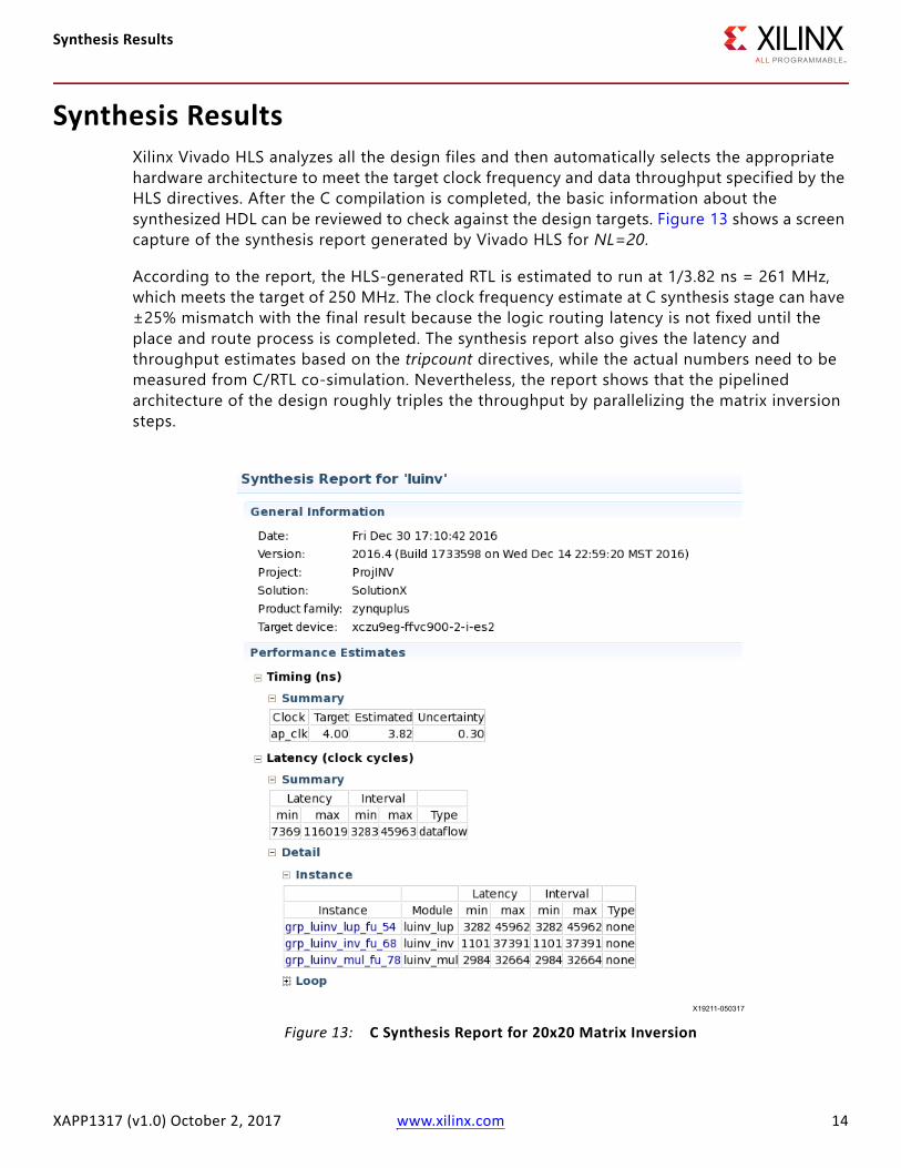
Synthesis ResultsXilinx Vivado HLS analyzes all the design files and then automatically selects the appropriate hardware architecture to meet the target clock frequency and data throughput specified by the HLS directives. After the C compilation is completed, the basic information about the synthesized HDL can be reviewed to check against the design targets. Figure 13 shows a screen capture of the synthesis report generated by Vivado HLS for NL=20.
According to the report, the HLS-generated RTL is estimated to run at 1/3.82 ns = 261 MHz, which meets the target of 250 MHz. The clock frequency estimate at C synthesis stage can have ±25% mismatch with the final result because the logic routing latency is not fixed until the place and route process is completed. The synthesis report also gives the latency and throughput estimates based on the tripcount directives, while the actual numbers need to be measured from C/RTL co-simulation. Nevertheless, the report shows that the pipelined architecture of the design roughly triples the throughput by parallelizing the matrix inversion steps.X-Ref Target - Figure 13
Figure 13: C Synthesis Report for 20x20 Matrix InversionX19211-050317
XAPP1317 (v1.0) October 2, 2017 www.xilinx.com 14

Verification Results
Verification ResultsIn the Vivado HLS design flow, functional verification consists of two steps. The first step is C functional verification that validates the C code against the golden test vectors. Using the rich file I/O functions provided by the C library, it is quite straightforward to code up a C test bench based on the pre-stored input and output test vectors. The reference design follows this approach, and the golden test vector contains 20 runs of a matrix inversion function with randomly generated matrices.
After the C behavior has been verified, and the C functions are synthesized into HDL, Vivado HLS can automatically generate an HDL testbench according to the C test code. This step is referred to as C/RTL Co-simulation, which ensures the HDL behavior matches C functionality. The outputs of the HDL design are compared to that of the golden test vectors to ensure the functionality is correct. At the end of the simulation, Vivado HLS prints the post checking results, which look like the following:
Time: 1802034 ns Iteration: 1 Process: /apatb_luinv_top/generate_sim_done_proc File: /home/mattr/appnote_luinv/ProjINV/SolutionX/sim/vhdl/luinv.autotb.vhdFailure: NORMAL EXIT (note: failure is to force the simulator to stop)Time: 1802034 ns Iteration: 1 Process: /apatb_luinv_top/generate_sim_done_proc File: /home/mattr/appnote_luinv/ProjINV/SolutionX/sim/vhdl/luinv.autotb.vhd$finish called at time : 1802034 nsrun: Time (s): cpu = 00:00:04 ; elapsed = 00:10:48 . Memory (MB): peak = 1010.938 ; gain = 0.000 ; free physical = 8690 ; free virtual = 45724## quitINFO: [Common 17-206] Exiting xsim at Fri Dec 30 17:23:12 2016...Total 20 Test Vectors, Err Count = 0.Test Passed!@I [SIM-1000] *** C/RTL co-simulation finished: PASS ***
The C/RTL co-simulator also reports the latency and throughput of the design measured from the simulation. These numbers are much more accurate than those reported at the C synthesis stage because the numbers of inner loops are functions of the outer loops, and the tripcount directive only gives the lower and upper bounds that can be quite different from the actual numbers. Figure 14 shows a screen capture of the co-simulator report.X-Ref Target - Figure 14
Figure 14: Co-simulation Result for 20x20 Matrix InversionX19210-050317
XAPP1317 (v1.0) October 2, 2017 www.xilinx.com 15

Verification Results
There is also an option to dump signal traces for manual debugging on the waveforms. Figure 15 shows a simulation waveform generated by Vivado Simulator 2016.4 for the test case of 20 random matrices. From the waveforms shown in Figure 15, it can be seen that the latency and throughput of the matrix inversion function match that in the C/RTL co-simulation report.
X-Ref Target - Figure 15
Figure 15: C and RTL Co-simulation Waveform (20x20 Matrix)X19209-050317
XAPP1317 (v1.0) October 2, 2017 www.xilinx.com 16

Implementation Results
Implementation ResultsXilinx Vivado HLS not only generates the HDL code of the C functions, but also provides a number of options to package the HDL into an IP for integration into a larger design using the Vivado Design Suite, e.g., System Generator and IP Integrator. For illustration purposes, IP Catalog has been selected for the example reference design.
The Vivado HLS tool automatically creates a Vivado project and synthesizes all the HDL code to validate the implementation performance. Table 1 summarizes the logic, maximum clock frequency, and the input interval of the matrix inversion module.
It is shown that the implemented design runs well above the target of a 250 MHz clock frequency. For various matrix sizes, the resource utilization almost remains the same while the latency and throughput are proportional to the number of elements in the matrix. This represents one trade-off between the resource and throughput. The C code can be modified for other resource and throughput trade-off options as well.
ConclusionThis application note demonstrates a method of building a pipelined floating-point matrix inversion function using the Vivado HLS tool which takes C code as an input and generates HDL code synthesizable on FPGAs. The C source code is easy to maintain and scalable to various FPGA parts, matrix sizes, and system clock frequencies.
Table 1: Implementation Results on the ZU9EG -2I DeviceMatrix Size 32x32 20x20 16x16 8x8
LUT 8,669 10,159 9,033 8,889Flip-flop 9,024 10,255 10,097 9,974DSP 60 60 60 60BRAM18K 44 22 22 22FMAX 351 MHz 330 MHz 313 MHz 330 MHzInput Interval 59,400 20,387 12,840 2,920Latency 203,637 66,063 45,861 10,765
XAPP1317 (v1.0) October 2, 2017 www.xilinx.com 17

Reference Design
Reference DesignDownload the reference design files for this application note from the Xilinx website.
Design File HierarchyThe directory structure underneath the top-level folder is as follows:
\src
-contains C design files and header files\tb
-contains a C design file that serves as the test bench\tv
-contains the input and output golden test vectors for verification purpose\m
-contains MATLAB functions for C design validation and test vector generation
Installation and Operating Instructions 1. Install Xilinx Vivado Design Suite 2016.4 or later.2. Unzip the design files into a clean directory.3. In the Vivado HLS command line window:
a. cd to the root of design directory.b. Enter vivado_hls run.tcl.c. Check that the synthesized design meets expectation.
XAPP1317 (v1.0) October 2, 2017 www.xilinx.com 18

References
Table 2 shows the reference design matrix.
ReferencesThis application note uses the following references:
1. Adaptive Beamforming for Radar: Floating-Point QRD+WBS in an FPGA (WP452)2. Vivado Design Suite User Guide: High-Level Synthesis (UG902)
Table 2: Reference Design MatrixParameter Description
GeneralDeveloper names Matt Ruan (Xilinx)Target devices UltraScale and UltraScale+ FPGAsSource code provided YesSource code format C, test vectors, and synthesize scriptDesign uses code and IP from existing Xilinx application note and reference designs or third party
No
SimulationFunctional simulation performed YesTiming simulation performed NoTest bench used for functional and timing simulations
Yes
Test bench format CSimulator software/version used Vivado Simulator 2016.4SPICE/IBIS simulations NoImplementationSynthesis software tools/versions used Vivado Design Suite 2016.4Implementation software tools/versions used
Vivado design tools 2016.4
Static timing analysis performed YesHardware VerificationHardware verified NoHardware platform used for verification N/A
XAPP1317 (v1.0) October 2, 2017 www.xilinx.com 19

Revision History
Revision HistoryThe following table shows the revision history for this document.
Please Read: Important Legal NoticesThe information disclosed to you hereunder (the “Materials”) is provided solely for the selection and use of Xilinx products. To the maximum extent permitted by applicable law: (1) Materials are made available "AS IS" and with all faults, Xilinx hereby DISCLAIMS ALL WARRANTIES AND CONDITIONS, EXPRESS, IMPLIED, OR STATUTORY, INCLUDING BUT NOT LIMITED TO WARRANTIES OF MERCHANTABILITY, NON-INFRINGEMENT, OR FITNESS FOR ANY PARTICULAR PURPOSE; and (2) Xilinx shall not be liable (whether in contract or tort, including negligence, or under any other theory of liability) for any loss or damage of any kind or nature related to, arising under, or in connection with, the Materials (including your use of the Materials), including for any direct, indirect, special, incidental, or consequential loss or damage (including loss of data, profits, goodwill, or any type of loss or damage suffered as a result of any action brought by a third party) even if such damage or loss was reasonably foreseeable or Xilinx had been advised of the possibility of the same. Xilinx assumes no obligation to correct any errors contained in the Materials or to notify you of updates to the Materials or to product specifications. You may not reproduce, modify, distribute, or publicly display the Materials without prior written consent. Certain products are subject to the terms and conditions of Xilinx’s limited warranty, please refer to Xilinx’s Terms of Sale which can be viewed at http://www.xilinx.com/legal.htm#tos; IP cores may be subject to warranty and support terms contained in a license issued to you by Xilinx. Xilinx products are not designed or intended to be fail-safe or for use in any application requiring fail-safe performance; you assume sole risk and liability for use of Xilinx products in such critical applications, please refer to Xilinx’s Terms of Sale which can be viewed at http://www.xilinx.com/legal.htm#tos.AUTOMOTIVE APPLICATIONS DISCLAIMERAUTOMOTIVE PRODUCTS (IDENTIFIED AS "XA" IN THE PART NUMBER) ARE NOT WARRANTED FOR USE IN THE DEPLOYMENT OF AIRBAGS OR FOR USE IN APPLICATIONS THAT AFFECT CONTROL OF A VEHICLE ("SAFETY APPLICATION") UNLESS THERE IS A SAFETY CONCEPT OR REDUNDANCY FEATURE CONSISTENT WITH THE ISO 26262 AUTOMOTIVE SAFETY STANDARD ("SAFETY DESIGN"). CUSTOMER SHALL, PRIOR TO USING OR DISTRIBUTING ANY SYSTEMS THAT INCORPORATE PRODUCTS, THOROUGHLY TEST SUCH SYSTEMS FOR SAFETY PURPOSES. USE OF PRODUCTS IN A SAFETY APPLICATION WITHOUT A SAFETY DESIGN IS FULLY AT THE RISK OF CUSTOMER, SUBJECT ONLY TO APPLICABLE LAWS AND REGULATIONS GOVERNING LIMITATIONS ON PRODUCT LIABILITY.© Copyright 2017 Xilinx, Inc. Xilinx, the Xilinx logo, Artix, ISE, Kintex, Spartan, Virtex, Vivado, Zynq, and other designated brands included herein are trademarks of Xilinx in the United States and other countries. All other trademarks are the property of their respective owners.
Date Version Revision10/02/2017 1.0 Initial Xilinx release.
XAPP1317 (v1.0) October 2, 2017 www.xilinx.com 20