scalar operand networks: design, implementation, and analysis
TRANSCRIPT
Scalar Operand Networks:Design, Implementation, and Analysis
Michael Bedford Taylor, Walter Lee, Saman Amarasinghe, Anant Agarwal
Abstract
The bypass paths and multiported register files in microprocessors serve as an implicit interconnect tocommunicate operand values among pipeline stages and multiple ALUs. Previous superscalar designs im-plemented this interconnect using centralized structures that do not scale with increasing ILP demands. Insearch of scalability, recent microprocessor designs in industry and academia exhibit a trend toward dis-tributed resources such as partitioned register files, banked caches, multiple independent compute pipelines,and even multiple program counters. Some of these partitioned microprocessor designs have begun to imple-ment bypassing and operand transport using point-to-point interconnects. We call interconnects optimizedfor scalar data transport, whether centralized or distributed, scalar operand networks. Although thesenetworks share many of the challenges of multiprocessor networks such as scalability and deadlock avoid-ance, they have many unique requirements, including ultra-low latencies (a few cycles versus tens of cycles)and ultra-fast operation-operand matching. This paper discusses the unique properties of scalar operandnetworks (SONs), examines alternative ways of implementing them, and introduces the AsTrO taxonomy todistinguish between them. It discusses the design of two alternative networks in the context of the Raw mi-croprocessor, and presents detailed timing, area and energy statistics for a real implementation. The paperalso presents a 5-tuple performance model for SONs and analyzes their performance sensitivity to networkproperties for ILP workloads.
1 Introduction
Today’s wide-issue microprocessor designers are finding it increasingly difficult to convert burgeoningsilicon resources into usable, general-purpose functional units. The problem is not so much that the area ofmicroprocessor structures is growing out of control; after all, Moore’s law’s exponential growth is easily ableto outpace a mere quadratic growth in area. Rather, it is the delay of the interconnect inside the processorblocks that has become unmanageable [1, 18, 33]. Thus, although we can build almost arbitrarily wide-issue processors, clocking them at high frequencies will become increasingly difficult. A case in point is theItanium 2 processor, which sports a zero-cycle fully-bypassed 6-way issue integer execution core. Despiteoccupying less than two percent of the processor die, this unit spends half of its critical path in the bypasspaths between the ALUs [16].
More generally, the pervasive use of global, centralized structures in these contemporary processor de-signs constrains not just the frequency-scalability of functional unit bypassing, but of many of the compo-nents of the processor that are involved in the task of naming, scheduling, orchestrating and routing operandsbetween functional units [18].
Building processors that can exploit increasing amounts of instruction-level parallelism (ILP) continuesto be important today. Many useful applications continue to display larger amounts of ILP than can be gain-fully exploited by current architectures. Furthermore, other forms of parallelism, such as data parallelism,pipeline parallelism, and coarse-grained parallelism, can easily be converted into ILP.
1
Chip multiprocessors, like IBM’s two-core Power4, hint at a scalable alternative for codes that can lever-age more functional units than a wide-issue microprocessor can provide. Research and commercial imple-mentations have demonstrated that multiprocessors based on scalable interconnects can be built to scale tothousands of nodes. Unfortunately, the high cost of inter-node operand routing (i.e. the cost of transferringthe output of an instruction on one node to the input of a dependent instruction on another node) is oftentoo high (tens to hundreds of cycles) for these multiprocessors to exploit ILP. Instead, the programmer isfaced with the unappealing task of explicitly parallelizing these programs. Further, because the differencebetween local and remote ALU communication costs is large (sometimes on the order of 30x), programmersand compilers need to employ entirely different algorithms to leverage parallelism at the two levels.
Seeking to scale ILP processors, recent microprocessor designs in industry and academia reveal a trendtowards distributed resources to varying degrees, such as partitioned register files, banked caches, mul-tiple independent compute pipelines, and even multiple program counters. These designs include UTAustin’s Grid[17], MIT’s Raw[31] and SCALE, Stanford’s Smart Memories[15], Wisconsin’s ILDP[9] andMultiscalar[24], Washington’s WaveScalar[27] and the Alpha 21264. Such partitioned or distributed micro-processor architectures have begun to replace the traditional centralized bypass network with a more generalinterconnect for bypassing and operand transport. With these more sophisticated interconnects come moresophisticated hardware or software algorithms to manage them. We label operand transport interconnectsand the algorithms that manage them, whether they are centralized or distributed, scalar operand networks.Specifically, a scalar operand network (SON1) is the set of mechanisms that joins the dynamic operands andoperations of a program in space to enact the computation specified by a program graph. These mechanismsinclude the physical interconnection network (referred to hereafter as the transport network) as well as theoperation-operand matching system that coordinates these values into a coherent computation. SONs canbe designed to have short wire lengths. Therefore, they can scale with increasing transistor counts. Further-more, because they can be designed around generalized transport networks, scalar operand networks canpotentially provide transport for other forms of data including I/O streams, cache misses, and synchroniza-tion signals.
Partitioned microprocessor architectures require scalar operand networks that combine the low-latencyand low-occupancy operand transport of wide-issue superscalar processors with the frequency-scalabilityof multiprocessor designs. Several recent studies have shown that partitioned microprocessors based onpoint-to-point SONs can successfully exploit fine-grained ILP. Lee et al. [13] showed that a compiler cansuccessfully schedule ILP on a partitioned architecture that uses a static point-to-point transport networkto achieve speedup that was commensurate with the degree of parallelism inherent in the applications. Na-garajan et al. [17] showed that the performance of a partitioned architecture using a dynamic point-to-pointtransport network was competitive with that of an idealized wide issue superscalar, even when the partitionedarchitecture counted a modest amount of wire delay.
Much as the study of interconnection networks is important for multiprocessors, we believe that thestudy of SONs in microprocessors is also important. Although these SONs share many of the challenges indesigning message passing networks, such as scalability and deadlock avoidance, they have many unique re-quirements including ultra-low latencies (a few cycles versus tens of cycles) and ultra-fast operation-operandmatching (0 cycles versus tens of cycles). This paper identifies five important challenges in designing SONs,and develops the AsTrO taxonomy for describing their logical properties. The paper also defines a param-eterized 5-tuple model that quantifies performance tradeoffs in the design of these networks. To show thatlarge-scale low-latency SONs are realizable, we also describe the details of the actual 16-way issue SONdesigned and implemented in the Raw microprocessor, using the 180 nm IBM SA-27E ASIC process.
One concrete contribution of this paper is that we show sender and receiver occupancies have a first orderimpact on ILP performance. For our benchmarks running on a 64-tile microprocessor (i.e., 64 ALUs, 64-waypartitioned register file, 64 instruction and data caches, connected by an SON) we measure a performancedrop of up to 20 percent when either the send or the receive occupancy is increased from zero to one cycle.
1pronounced ess-oh-en.
2
The performance loss due to network transport contention, on the other hand, was discovered to averageonly 5 percent for a 64-tile Raw mesh. These results lead us to conclude that whether the network transportis static or dynamic is less important (at least for up to 64 nodes) than whether the SON offers efficientsupport for matching operands with the intended operations.
The paper proceeds as follows. Section 2 provides background on scalar operand networks and theirevolution. Section 3 describes the key challenges in designing scalable SONs; these challenges derive from acombined ancestry of multiprocessor interconnects and primordial uniprocessor bypass networks. Section 4introduces a taxonomy for the logical structure of SONs. Section 5 describes the design of two exampleSONs. Section 6 discusses the scalar operand network implementation in the Raw processor. Section 7quantifies the sensitivity of ILP performance to network properties, and Section 8 examines application-specific operand usage statistics. Section 9 presents related work, and Section 10 concludes the paper.
2 Evolution of Scalar Operand Networks
Register File
W
R1
R2
Figure 1. A simple SON.
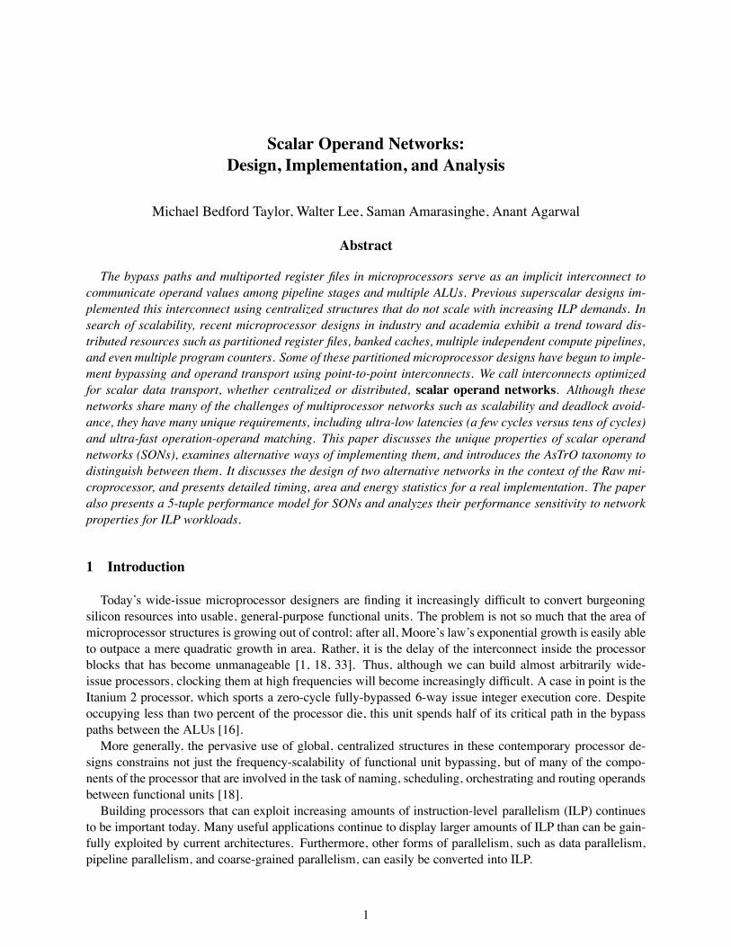
The role of an SON is to join the dynamic operands and operationsof a program in space to enact the computation specified by a programgraph. An SON includes both the physical interconnection network (thetransport network) and the associated operation-operand matching algo-rithms (hardware or software) that coordinate operands and operationsinto a coherent computation. Designing SONs was a simple task duringthe era of non-pipelined processors, but as our demands for parallelism(e.g., multiple ALUs, large register name spaces), clock rate (e.g., deeppipelines), and scalability (e.g., partitioned register files) have increased,this task has become much more complex. This section describes theevolution of SONs – from the early, monolithic register file intercon-nects to the more recent ones that incorporate routed point-to-point mesh interconnects.
A non-pipelined processor with a register file and ALU contains a simple, specialized form of an SON.The logical register numbers provide a naming system for connecting the inputs and outputs of the opera-tions. The number of logical register names sets the upper bound on the number of live values that can beheld in the SON.
Figure 1 emphasizes the role of a register file as a device capable of performing two parallel routes fromany two of a collection of registers to the output ports of the register file, and one route from the input of theregister file to any of the registers. Each arc in the diagram represents a possible operand route that may beperformed on each cycle. This interconnect-centric view of a register file becomes increasingly appropriateas as wire delays worsen in our fabrication processes.
Register File
W
R1
R2Mux
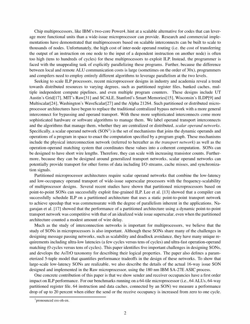
Figure 2. SON in a pipelined proces-sor with bypassing links.
Figure 2 shows a pipelined, bypassed register-ALU pair.The SON now adds several new paths, multiplexers andpipeline registers, and partitions operand traffic into twoclasses: “live” operands routed directly from functional unitto functional unit, and “quiescent-but-live” operands routed“through time” (via self routes in the register file) and theneventually to the ALU. The partitioning improves the cycletime because the routing complexity of the live values is lessthan the routing complexity of the resident register set. Thistransformation also changes the naming system – the registersin the pipeline dynamically shadow the registers in the registerfile.
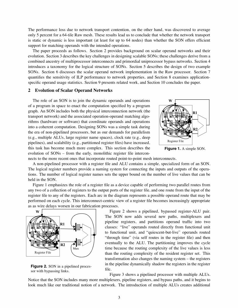
Figure 3 shows a pipelined processor with multiple ALUs.Notice that the SON includes many more multiplexers, pipeline registers, and bypass paths, and it begins tolook much like our traditional notion of a network. The introduction of multiple ALUs creates additional
3
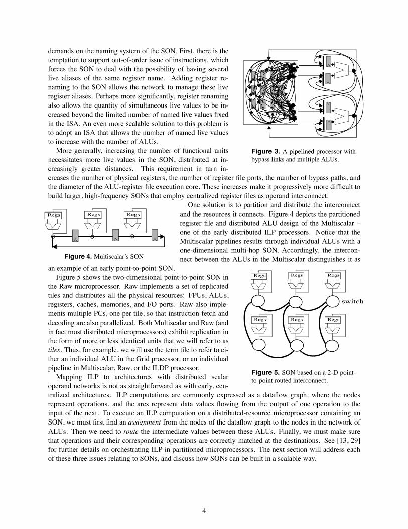
Figure 3. A pipelined processor withbypass links and multiple ALUs.
demands on the naming system of the SON. First, there is thetemptation to support out-of-order issue of instructions. whichforces the SON to deal with the possibility of having severallive aliases of the same register name. Adding register re-naming to the SON allows the network to manage these liveregister aliases. Perhaps more significantly, register renamingalso allows the quantity of simultaneous live values to be in-creased beyond the limited number of named live values fixedin the ISA. An even more scalable solution to this problem isto adopt an ISA that allows the number of named live valuesto increase with the number of ALUs.
More generally, increasing the number of functional unitsnecessitates more live values in the SON, distributed at in-creasingly greater distances. This requirement in turn in-creases the number of physical registers, the number of register file ports, the number of bypass paths, andthe diameter of the ALU-register file execution core. These increases make it progressively more difficult tobuild larger, high-frequency SONs that employ centralized register files as operand interconnect.
Regs Regs Regs
Figure 4. Multiscalar’s SON
One solution is to partition and distribute the interconnectand the resources it connects. Figure 4 depicts the partitionedregister file and distributed ALU design of the Multiscalar –one of the early distributed ILP processors. Notice that theMultiscalar pipelines results through individual ALUs with aone-dimensional multi-hop SON. Accordingly, the intercon-nect between the ALUs in the Multiscalar distinguishes it as
an example of an early point-to-point SON.Regs
Regs
Regs
Regs
Regs
Regs
switch
Figure 5. SON based on a 2-D point-to-point routed interconnect.
Figure 5 shows the two-dimensional point-to-point SON inthe Raw microprocessor. Raw implements a set of replicatedtiles and distributes all the physical resources: FPUs, ALUs,registers, caches, memories, and I/O ports. Raw also imple-ments multiple PCs, one per tile, so that instruction fetch anddecoding are also parallelized. Both Multiscalar and Raw (andin fact most distributed microprocessors) exhibit replication inthe form of more or less identical units that we will refer to astiles. Thus, for example, we will use the term tile to refer to ei-ther an individual ALU in the Grid processor, or an individualpipeline in Multiscalar, Raw, or the ILDP processor.
Mapping ILP to architectures with distributed scalaroperand networks is not as straightforward as with early, cen-tralized architectures. ILP computations are commonly expressed as a dataflow graph, where the nodesrepresent operations, and the arcs represent data values flowing from the output of one operation to theinput of the next. To execute an ILP computation on a distributed-resource microprocessor containing anSON, we must first find an assignment from the nodes of the dataflow graph to the nodes in the network ofALUs. Then we need to route the intermediate values between these ALUs. Finally, we must make surethat operations and their corresponding operations are correctly matched at the destinations. See [13, 29]for further details on orchestrating ILP in partitioned microprocessors. The next section will address eachof these three issues relating to SONs, and discuss how SONs can be built in a scalable way.
4
3 Challenges in the Design of Scalar Operand Networks
This section identifies and discusses some of the key challenges in the design of scalar operand networks:frequency scalability, bandwidth scalability, efficient operation-operand matching, deadlock and starvation,and handling exceptional events.
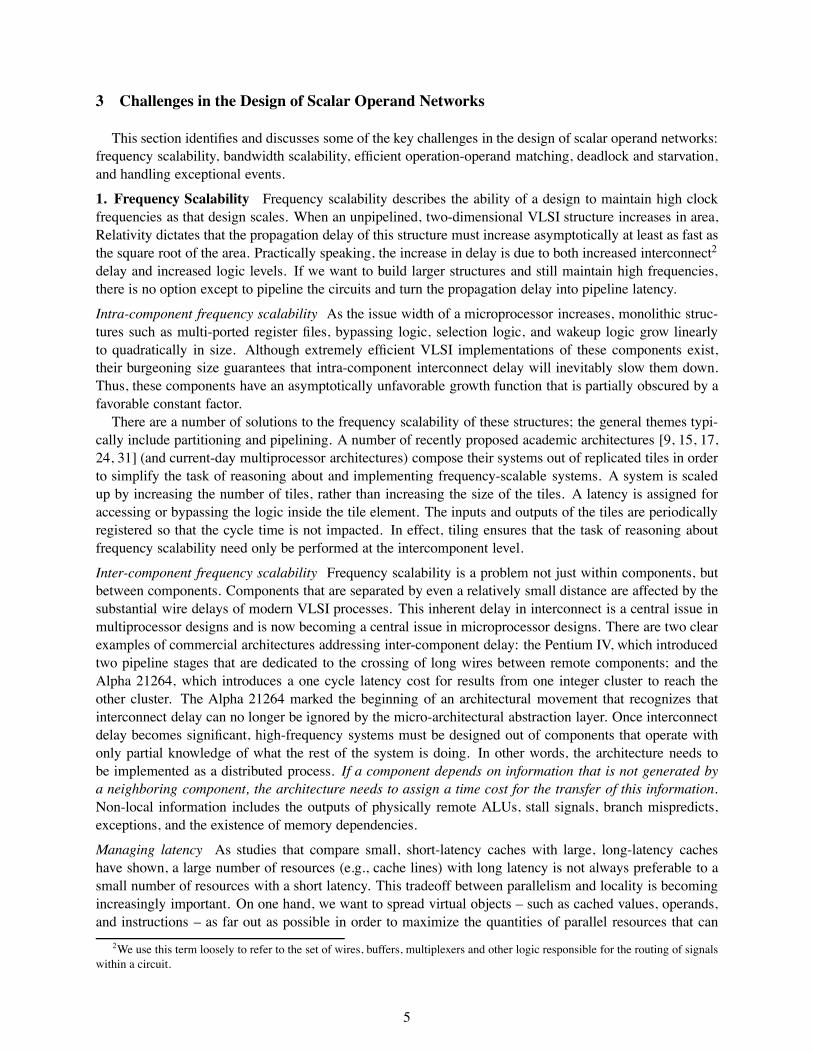
1. Frequency Scalability Frequency scalability describes the ability of a design to maintain high clockfrequencies as that design scales. When an unpipelined, two-dimensional VLSI structure increases in area,Relativity dictates that the propagation delay of this structure must increase asymptotically at least as fast asthe square root of the area. Practically speaking, the increase in delay is due to both increased interconnect2
delay and increased logic levels. If we want to build larger structures and still maintain high frequencies,there is no option except to pipeline the circuits and turn the propagation delay into pipeline latency.
Intra-component frequency scalability As the issue width of a microprocessor increases, monolithic struc-tures such as multi-ported register files, bypassing logic, selection logic, and wakeup logic grow linearlyto quadratically in size. Although extremely efficient VLSI implementations of these components exist,their burgeoning size guarantees that intra-component interconnect delay will inevitably slow them down.Thus, these components have an asymptotically unfavorable growth function that is partially obscured by afavorable constant factor.
There are a number of solutions to the frequency scalability of these structures; the general themes typi-cally include partitioning and pipelining. A number of recently proposed academic architectures [9, 15, 17,24, 31] (and current-day multiprocessor architectures) compose their systems out of replicated tiles in orderto simplify the task of reasoning about and implementing frequency-scalable systems. A system is scaledup by increasing the number of tiles, rather than increasing the size of the tiles. A latency is assigned foraccessing or bypassing the logic inside the tile element. The inputs and outputs of the tiles are periodicallyregistered so that the cycle time is not impacted. In effect, tiling ensures that the task of reasoning aboutfrequency scalability need only be performed at the intercomponent level.
Inter-component frequency scalability Frequency scalability is a problem not just within components, butbetween components. Components that are separated by even a relatively small distance are affected by thesubstantial wire delays of modern VLSI processes. This inherent delay in interconnect is a central issue inmultiprocessor designs and is now becoming a central issue in microprocessor designs. There are two clearexamples of commercial architectures addressing inter-component delay: the Pentium IV, which introducedtwo pipeline stages that are dedicated to the crossing of long wires between remote components; and theAlpha 21264, which introduces a one cycle latency cost for results from one integer cluster to reach theother cluster. The Alpha 21264 marked the beginning of an architectural movement that recognizes thatinterconnect delay can no longer be ignored by the micro-architectural abstraction layer. Once interconnectdelay becomes significant, high-frequency systems must be designed out of components that operate withonly partial knowledge of what the rest of the system is doing. In other words, the architecture needs tobe implemented as a distributed process. If a component depends on information that is not generated bya neighboring component, the architecture needs to assign a time cost for the transfer of this information.Non-local information includes the outputs of physically remote ALUs, stall signals, branch mispredicts,exceptions, and the existence of memory dependencies.
Managing latency As studies that compare small, short-latency caches with large, long-latency cacheshave shown, a large number of resources (e.g., cache lines) with long latency is not always preferable to asmall number of resources with a short latency. This tradeoff between parallelism and locality is becomingincreasingly important. On one hand, we want to spread virtual objects – such as cached values, operands,and instructions – as far out as possible in order to maximize the quantities of parallel resources that can
2We use this term loosely to refer to the set of wires, buffers, multiplexers and other logic responsible for the routing of signalswithin a circuit.
5
be leveraged. On the other hand, we want to minimize communication latency by placing communicatingobjects close together, especially if they are on the critical path. These conflicting desires motivate us todesign architectures with non-uniform costs; so that rather than paying the maximum cost of accessing aobject (e.g., the latency of the DRAM), we pay a cost that is proportional to the delay of accessing thatparticular object (e.g., a hit in the first-level cache). This optimization is further aided if we can exploitlocality among virtual objects and place related objects (e.g. communicating instructions) close together.
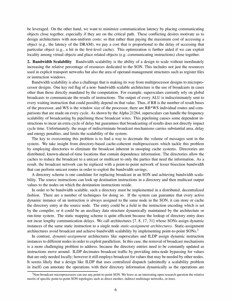
2. Bandwidth Scalability Bandwidth scalability is the ability of a design to scale without inordinatelyincreasing the relative percentage of resources dedicated to the SON. This includes not just the resourcesused in explicit transport networks but also the area of operand-management structures such as register filesor instruction windows.
Bandwidth scalability is also a challenge that is making its way from multiprocessor designs to micropro-cessor designs. One key red flag of a non- bandwidth scalable architecture is the use of broadcasts in casesother than those directly mandated by the computation. For example, superscalars currently rely on globalbroadcasts to communicate the results of instructions. The output of every ALU is indiscriminately sent toevery waiting instruction that could possibly depend on that value. Thus, if RB is the number of result busesof the processor, and WS is the window size of the processor, there are RB*WS individual routes and com-parisons that are made on every cycle. As shown by the Alpha 21264, superscalars can handle the frequencyscalability of broadcasting by pipelining these broadcast wires. This pipelining causes some dependent in-structions to incur an extra cycle of delay but guarantees that broadcasting of results does not directly impactcycle time. Unfortunately, the usage of indiscriminate broadcast mechanisms carries substantial area, delayand energy penalties, and limits the scalability of the system.
The key to overcoming this problem is to find a way to decimate the volume of messages sent in thesystem. We take insight from directory-based cache-coherent multiprocessors which tackle this problemby employing directories to eliminate the broadcast inherent in snooping cache systems. Directories aredistributed, known-ahead-of-time locations that contain dependence information. The directories allow thecaches to reduce the broadcast to a unicast or multicast to only the parties that need the information. As aresult, the broadcast network can be replaced with a point-to-point network of lesser bisection bandwidththat can perform unicast routes in order to exploit the bandwidth savings.
A directory scheme is one candidate for replacing broadcast in an SON and achieving bandwidth scala-bility. The source instructions can look up destination instructions in a directory and then multicast outputvalues to the nodes on which the destination instructions reside.
In order to be bandwidth scalable, such a directory must be implemented in a distributed, decentralizedfashion. There are a number of techniques for doing so. If the system can guarantee that every activedynamic instance of an instruction is always assigned to the same node in the SON, it can store or cachethe directory entry at the source node. The entry could be a field in the instruction encoding which is setby the compiler, or it could be an auxiliary data structure dynamically maintained by the architecture orrun-time system. The static mapping scheme is quite efficient because the lookup of directory entry doesnot incur lengthy communication delays. We call architectures [7, 8, 17, 31] whose SONs assign dynamicinstances of the same static instruction to a single node static-assignment architectures. Static-assignmentarchitectures avoid broadcast and achieve bandwidth scalability by implementing point-to-point SONs.3
In contrast, dynamic-assignment architectures like superscalars and ILDP assign dynamic instructioninstances to different nodes in order to exploit parallelism. In this case, the removal of broadcast mechanismsis a more challenging problem to address, because the directory entries need to be constantly updated asinstructions move around. ILDP decimates broadcast traffic by providing intra-node bypassing for valuesthat are only needed locally; however it still employs broadcast for values that may be needed by other nodes.It seems likely that a design like ILDP that uses centralized dispatch (admittedly a scalability problemin itself) can annotate the operations with their directory information dynamically as the operations are
3Non-broadcast microprocessors can use any point-to-point SON. We leave as an interesting open research question the relativemerits of specific point-to-point SON topologies such as direct meshes, indirect multistage networks, or trees.
6
dispatched to the physical operators for processing. In fact, this approach is explored and analyzed by [20].We believe the issue of whether a scalable dynamic assignment architecture can replace the broadcast witha multicast using a distributed register file or directory system is an interesting open research question.
3. Efficient Operation-Operand Matching Operation-operand matching is the process of gatheringoperands and operations to meet at some point in space to perform the desired computation. If operation-operand matching can not be done efficiently, there is little point in scaling the issue-width of a processingsystem, because the benefits will rarely outweigh the overhead.
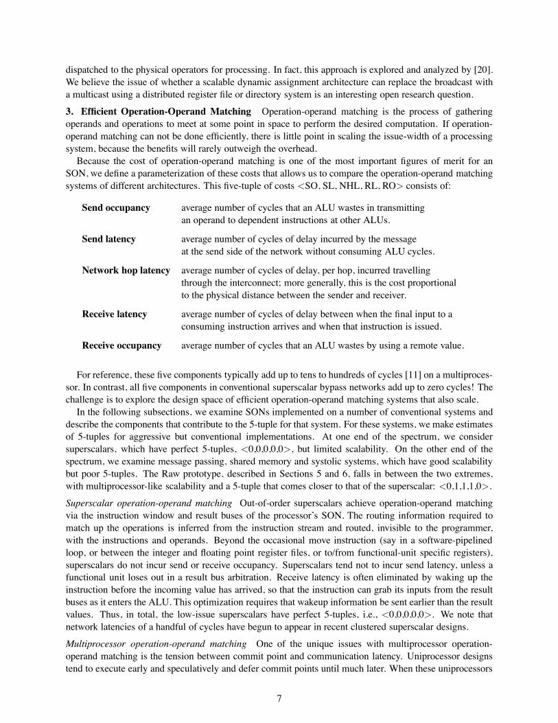
Because the cost of operation-operand matching is one of the most important figures of merit for anSON, we define a parameterization of these costs that allows us to compare the operation-operand matchingsystems of different architectures. This five-tuple of costs <SO, SL, NHL, RL, RO> consists of:
Send occupancy average number of cycles that an ALU wastes in transmittingan operand to dependent instructions at other ALUs.
Send latency average number of cycles of delay incurred by the messageat the send side of the network without consuming ALU cycles.
Network hop latency average number of cycles of delay, per hop, incurred travellingthrough the interconnect; more generally, this is the cost proportionalto the physical distance between the sender and receiver.
Receive latency average number of cycles of delay between when the final input to aconsuming instruction arrives and when that instruction is issued.
Receive occupancy average number of cycles that an ALU wastes by using a remote value.
For reference, these five components typically add up to tens to hundreds of cycles [11] on a multiproces-sor. In contrast, all five components in conventional superscalar bypass networks add up to zero cycles! Thechallenge is to explore the design space of efficient operation-operand matching systems that also scale.
In the following subsections, we examine SONs implemented on a number of conventional systems anddescribe the components that contribute to the 5-tuple for that system. For these systems, we make estimatesof 5-tuples for aggressive but conventional implementations. At one end of the spectrum, we considersuperscalars, which have perfect 5-tuples, <0,0,0,0,0>, but limited scalability. On the other end of thespectrum, we examine message passing, shared memory and systolic systems, which have good scalabilitybut poor 5-tuples. The Raw prototype, described in Sections 5 and 6, falls in between the two extremes,with multiprocessor-like scalability and a 5-tuple that comes closer to that of the superscalar: <0,1,1,1,0>.
Superscalar operation-operand matching Out-of-order superscalars achieve operation-operand matchingvia the instruction window and result buses of the processor’s SON. The routing information required tomatch up the operations is inferred from the instruction stream and routed, invisible to the programmer,with the instructions and operands. Beyond the occasional move instruction (say in a software-pipelinedloop, or between the integer and floating point register files, or to/from functional-unit specific registers),superscalars do not incur send or receive occupancy. Superscalars tend not to incur send latency, unless afunctional unit loses out in a result bus arbitration. Receive latency is often eliminated by waking up theinstruction before the incoming value has arrived, so that the instruction can grab its inputs from the resultbuses as it enters the ALU. This optimization requires that wakeup information be sent earlier than the resultvalues. Thus, in total, the low-issue superscalars have perfect 5-tuples, i.e., <0,0,0,0,0>. We note thatnetwork latencies of a handful of cycles have begun to appear in recent clustered superscalar designs.
Multiprocessor operation-operand matching One of the unique issues with multiprocessor operation-operand matching is the tension between commit point and communication latency. Uniprocessor designstend to execute early and speculatively and defer commit points until much later. When these uniprocessors
7
are integrated into multiprocessor systems, all potential communication must be deferred until the relevantinstructions have reached the commit point. In a modern-day superscalar, this deferral means that therecould be tens or hundreds of cycles that pass between the time that a communication instruction executesand the time at which it can legitimately send its value on to the consuming node. We call the time it takesfor an instruction to commit the commit latency. Until these networks support speculative sends and receives(as with a superscalar!), the send latency of these networks will be adversely impacted.
Multiprocessors employ a variety of communication mechanisms; two flavors are message passing andshared memory. In [29], we derived the 5-tuple of a message-passing implementation of an SON as rang-ing between <3,2+c,1,1,7> and <3,3+c,1,1,12> (referred to subsequently as MsgFast and MsgSlow) withc being the commit latency of the processor. An aggressive shared-memory SON implementation wasdetermined to have a 5-tuple of <1,14+c,2,14,1>. For length purposes, we limit discussion in the nextsubsection to message-passing; more discussion of shared memory and systolic array SON implementationscan be found in [29] and in part, in Supplemental Sections 11 and 12.
Message-passing operation-operand matching In discussing message-passing operation-operand matching,we assume that a dynamic transport network [5] is being employed to transport operands between nodes.Implementing operation-operand matching using a message-passing style network has two key challenges.
First, nodes need a processor-network interface that allows low-overhead sends and receives of operands.In an instruction-mapped interface, special send and receive instructions are used for communication; ina register-mapped interface, special register names correspond to communication ports. Using either in-terface, the sender must specify the destination(s) of the out-going operands. (Recall that the superscalaruses indiscriminate broadcasting to solve this problem.) There are a variety of methods for specifying thisinformation. For instruction-mapped interfaces, the send instruction can leave encoding space (the log ofthe maximum number of nodes) or take a parameter to specify the destination node. For register-mappedinterfaces, an additional word may have to be sent to specify the destination. Finally, dynamic transportnetworks typically do not support multicast, so multiple message sends may be required for operands thathave non-unit fanout. These factors will impact the send and receive occupancies.
Second, receiving nodes must match incoming operands with the appropriate instruction. Because timingvariances due to I/O, cache misses, and interrupts can delay nodes arbitrarily, there is no set arrival order foroperands sent over dynamic transport. Thus, a tag must be sent along with each operand. When the operandarrives at the destination, it needs to be demultiplexed to align with the ordering of instructions in thereceiver instruction stream. Conventional message-passing implementations must do this in software [32],or in a combination of hardware and software [14], causing a considerable receive occupancy.
4. Deadlock and starvation Superscalar SONs use relatively centralized structures to flow control in-structions and operands so that internal buffering cannot be overcommitted. With less centralized SONs,such global knowledge is more difficult to attain. If the processing elements independently produce morevalues than the SON has storage space, then either data loss or deadlock must occur [6, 25]. This problemis not unusual; in fact some of the earliest large-scale SON research – the dataflow machines – encoun-tered serious problems with the overcommitment of storage space and resultant deadlock [2]. Alternatively,priorities in the operand network may lead to a lack of fairness in the execution of instructions, whichmay severely impact performance. Transport-related deadlock can be roughly divided into two categories;endpoint deadlock, resulting from a lack of storage at the endpoints of messages, and in-network deadlock,which is deadlock inside the transport network itself. Because a number of effective solutions for in-networkdeadlock have been proposed in the literature, endpoint deadlock is the main issue for concern in SONs.
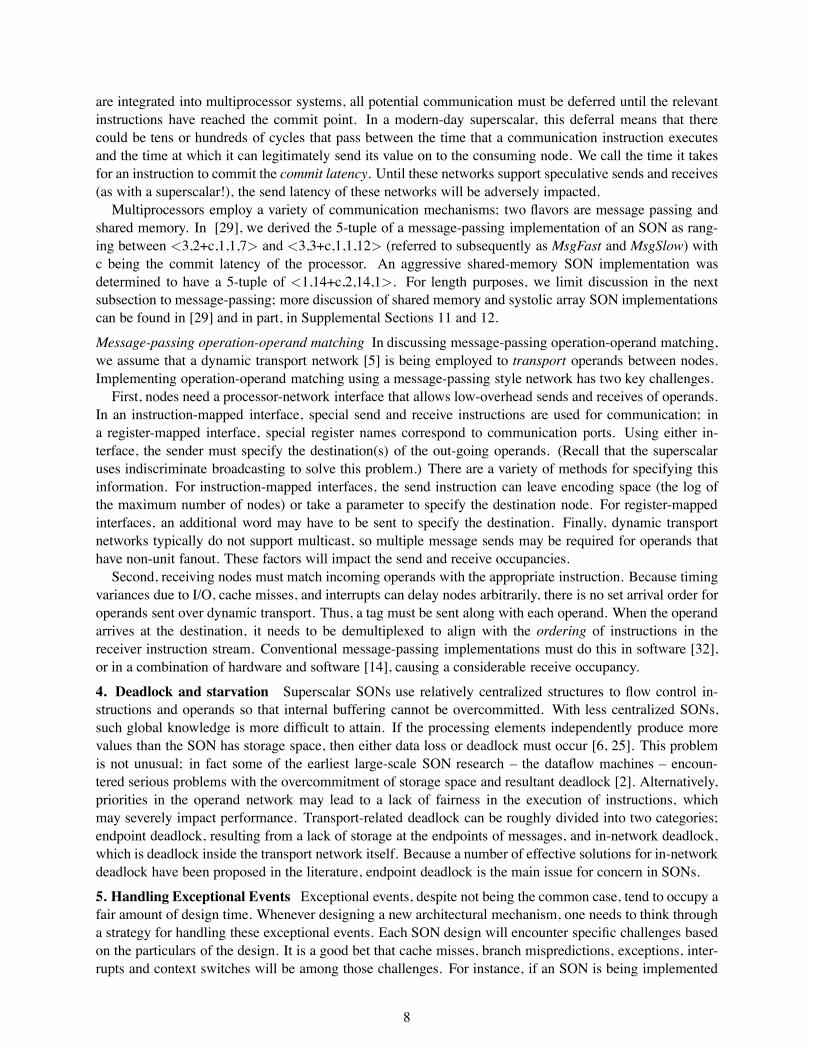
5. Handling Exceptional Events Exceptional events, despite not being the common case, tend to occupy afair amount of design time. Whenever designing a new architectural mechanism, one needs to think througha strategy for handling these exceptional events. Each SON design will encounter specific challenges basedon the particulars of the design. It is a good bet that cache misses, branch mispredictions, exceptions, inter-rupts and context switches will be among those challenges. For instance, if an SON is being implemented
8
tatic
ynamic
ynamic ynamic tatic tatic tatic
ynamic
RawDynamicGRID
WaveScalar ILDP OOO Superscalar
S D
S
D
S D S D
taticS
RawStatic
ynamicD
O
As
Tr
signment
ansport
rdering
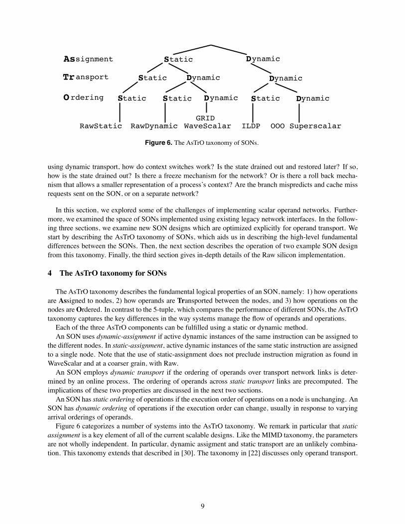
Figure 6. The AsTrO taxonomy of SONs.
using dynamic transport, how do context switches work? Is the state drained out and restored later? If so,how is the state drained out? Is there a freeze mechanism for the network? Or is there a roll back mecha-nism that allows a smaller representation of a process’s context? Are the branch mispredicts and cache missrequests sent on the SON, or on a separate network?
In this section, we explored some of the challenges of implementing scalar operand networks. Further-more, we examined the space of SONs implemented using existing legacy network interfaces. In the follow-ing three sections, we examine new SON designs which are optimized explicitly for operand transport. Westart by describing the AsTrO taxonomy of SONs, which aids us in describing the high-level fundamentaldifferences between the SONs. Then, the next section describes the operation of two example SON designfrom this taxonomy. Finally, the third section gives in-depth details of the Raw silicon implementation.
4 The AsTrO taxonomy for SONs
The AsTrO taxonomy describes the fundamental logical properties of an SON, namely: 1) how operationsare Assigned to nodes, 2) how operands are Transported between the nodes, and 3) how operations on thenodes areOrdered. In contrast to the 5-tuple, which compares the performance of different SONs, the AsTrOtaxonomy captures the key differences in the way systems manage the flow of operands and operations.
Each of the three AsTrO components can be fulfilled using a static or dynamic method.An SON uses dynamic-assignment if active dynamic instances of the same instruction can be assigned to
the different nodes. In static-assignment, active dynamic instances of the same static instruction are assignedto a single node. Note that the use of static-assignment does not preclude instruction migration as found inWaveScalar and at a coarser grain, with Raw.
An SON employs dynamic transport if the ordering of operands over transport network links is deter-mined by an online process. The ordering of operands across static transport links are precomputed. Theimplications of these two properties are discussed in the next two sections.
An SON has static ordering of operations if the execution order of operations on a node is unchanging. AnSON has dynamic ordering of operations if the execution order can change, usually in response to varyingarrival orderings of operands.
Figure 6 categorizes a number of systems into the AsTrO taxonomy. We remark in particular that staticassignment is a key element of all of the current scalable designs. Like the MIMD taxonomy, the parametersare not wholly independent. In particular, dynamic assigment and static transport are an unlikely combina-tion. This taxonomy extends that described in [30]. The taxonomy in [22] discusses only operand transport.
9
5 Operation of the RawDynamic and RawStatic SONs
In this section, we describe RawDynamic, an SDS SON, and RawStatic, an SSS SON. We use the termRawStatic to refer to the SSS SON implemented on top of the hardware resources in the actual Raw proces-sor prototype. This is the SON that the Raw hardware actually uses. RawDynamic refers to an SDS SONimplemented with the combination of the existing Raw hardware and a few additional hardware features.These features will be discussed in detail in this section.
DR
AM
DR
AM
DR
AM
PCI x 2
PCI x 2
DRAM
D/A
DRAM
DRAM
DRAM
DRAM
CS
CS
CS
CS
CS
CS
CS
CS
CS
CS
CS
CS
CS
CS
CS
CS
Compute Pipeline
SMEMPC
X
DATACACHEPC
IMEM
DR
AM
DR
AM
DR
AM
PCI x 2
PCI x 2
DRAM
D/A
DRAM
DRAM
DRAM
DRAM
CS
CS
CS
CS
CS
CS
CS
CS
CS
CS
CS
CS
CS
CS
CS
CS
DR
AM
DR
AM
DR
AM
PCI x 2
PCI x 2
DRAM
D/A
DRAM
DRAM
DRAM
DRAM
CS
CS
CS
CS
CS
CS
CS
CS
CS
CS
CS
CS
CS
CS
CS
CS
CS
CS
CS
CS
CS
CS
CS
CS
CS
CS
CS
CS
CS
CS
CS
CS
CS
CS
CS
CS
CS
CS
CS
CS
CS
CS
CS
CS
CS
CS
CS
CS
CS
CS
CS
CS
CS
CS
CS
CS
CS
CS
CS
CS
CS
CS
CS
CS
Compute Pipeline
SMEMPC
X
DATACACHEPC
IMEM
IF RFDA TL
M1
F P
E
U WB
r26
r27
r25
r24
InputFIFOsfromStaticRouter
r26
r27
r25
r24
OutputFIFOstoStaticRouter
0-cycle“local bypassnetwork”
M2
TV
F4IF RFD
A TL
M1
F P
E
U WB
r26
r27
r25
r24
InputFIFOsfromStaticRouter
r26
r27
r25
r24
OutputFIFOstoStaticRouter
0-cycle“local bypassnetwork”
M2
TV
F4IF RFD
A TL
M1
F P
E
U WB
r26
r27
r25
r24
InputFIFOsfromStaticRouter
r26
r27
r25
r24
OutputFIFOstoStaticRouter
0-cycle“local bypassnetwork”
M2
TV
F4
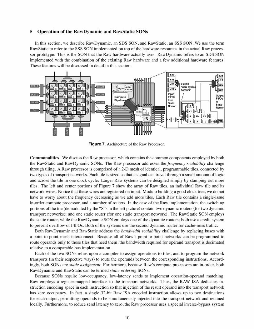
Figure 7. Architecture of the Raw Processor.
Commonalities We discuss the Raw processor, which contains the common components employed by boththe RawStatic and RawDynamic SONs. The Raw processor addresses the frequency scalability challengethrough tiling. A Raw processor is comprised of a 2-D mesh of identical, programmable tiles, connected bytwo types of transport networks. Each tile is sized so that a signal can travel through a small amount of logicand across the tile in one clock cycle. Larger Raw systems can be designed simply by stamping out moretiles. The left and center portions of Figure 7 show the array of Raw tiles, an individual Raw tile and itsnetwork wires. Notice that these wires are registered on input. Modulo building a good clock tree, we do nothave to worry about the frequency decreasing as we add more tiles. Each Raw tile contains a single-issuein-order compute processor, and a number of routers. In the case of the Raw implementation, the switchingportions of the tile (demarkated by the “S”s in the left picture) contain two dynamic routers (for two dynamictransport networks); and one static router (for one static transport network). The RawStatic SON employsthe static router, while the RawDynamic SON employs one of the dynamic routers; both use a credit systemto prevent overflow of FIFOs. Both of the systems use the second dynamic router for cache-miss traffic.
Both RawDynamic and RawStatic address the bandwidth scalability challenge by replacing buses witha point-to-point mesh interconnect. Because all of Raw’s point-to-point networks can be programmed toroute operands only to those tiles that need them, the bandwidth required for operand transport is decimatedrelative to a comparable bus implementation.
Each of the two SONs relies upon a compiler to assign operations to tiles, and to program the networktransports (in their respective ways) to route the operands between the corresponding instructions. Accord-ingly, both SONs are static assignment. Furthermore, because Raw’s compute processors are in-order, bothRawDynamic and RawStatic can be termed static ordering SONs.
Because SONs require low-occupancy, low-latency sends to implement operation-operand matching,Raw employs a register-mapped interface to the transport networks. Thus, the RAW ISA dedicates in-struction encoding space in each instruction so that injection of the result operand into the transport networkhas zero occupancy. In fact, a single 32-bit Raw ISA encoded instruction allows up to two destinationsfor each output, permitting operands to be simultaneously injected into the transport network and retainedlocally. Furthermore, to reduce send latency to zero, the Raw processor uses a special inverse-bypass system
10
for both static and dynamic routers. This inverse-bypass system pulls operands from the local bypass net-work of the processor and into the output FIFOs as soon as they are ready, rather than just at the writebackstage or through the register file [7]. In both cases, the logic must ensure that operands are pulled out ofthe bypass paths in-order. For the static network, this is because operands must be injected into the networkin a known order, and for the dynamic network, because the ordering of words in a message payload mustbe respected. This interface is shown on the right hand portion of third component of the Raw processordiagram. Inverse bypassing, combined with an early commit point in the Raw processor, reduces the sendlatency of operation-operand matching by up to 4 cycles. In effect, we’ve deliberately designed an earlycommit point into our processor in order to eliminate the common multiprocessor communication-commitdelay (i.e., c = 0) that was described in the Challenges section.
Register-mapped input FIFOs are used to provide zero-occupancy, unit-latency receives. One cycle ofreceive latency is incurred because the receive FIFOs are scheduled and accessed in the dispatch stage of theprocessor. This cycle of receive latency could be eliminated as with a superscalar if the valid bits are routedone cycle ahead of the data bits in the network.
Finally, Raw’s implementation of a 0-cycle bypass for those operands that a compute processor bothproduces and uses locally further reduces the necessity to pay the full operation-operand matching cost.
Both RawStatic and RawDynamic support exceptional events, the final challenge. Branch conditions andjump pointers are transmitted over the transport network, just like data. Raw’s interrupt model allows eachtile to take and process interrupts individually. Compute processor cache misses stall only the computeprocessor that misses. Tiles that try to use the result of a cache-missing load from another tile will block,waiting for the value to arrive over the transport network. These cache misses are processed over a separatedynamic transport. Raw supports context switches by draining and restoring the transport network contents.This network state is saved into a context block and then restored when the process is switched back in.
5.1 Operation of RawDynamic, an SDS SON
RawDynamic differs from RawStatic because it uses the Raw processor’s dynamic dimension-ordered [26] worm-hole routed [5] network to route operands between tiles. Thus, it is a dynamic transportSON. Dimension-ordered routing is in-network deadlock-free for meshes without end-around connections.
Because RawDynamic uses a dynamic transport network, it needs to extend the existing Raw computeprocessor ISA by encoding the destination address or offset in the instruction, rather than just the choiceof network to inject into. Furthermore, since the instruction may have multiple consumers, it is typicalto encode multiple consumers in a single instruction. Finally, because dynamic transport message arrivalorderings are impacted by the time at which a message is sent, a system intended to tolerate unpredictableevents like cache misses must include a numeric index with each operand that tells the recipient exactlywhich operand it is that has arrived. Thus, it is reasonable to conclude that dynamic transport SONs willhave wider instruction words and wider transport network sizes4 than the equivalent static transport SONs.Additionally, for efficient implementation of multicast and broadcast operations (such as a jr, or operandswith high fanout), the equivalent dynamic transport SON may need more injection ports into the network.In fact, the question of low-occupancy, low-latency broadcast and multicast in dynamic transport networksappears to be an area of active research[19].
We now examine the transport portion of the RawDynamic SON. The Raw dynamic router has signif-icantly deeper logic levels than the Raw static router for determining the route of incoming operands. Inour aggressive implementation, we speculatively assume that incoming dynamic routes are straight-through-routes, which is the common case in dimension-ordered designs [23]. As a result, we were able to optimizethis path and reduce the latency of most routes to a single cycle per hop. However, an additional cycle of
4If the transport width is wide enough to send all components of an operand in a single message, inverse-bypassing could bemodified to allow operands to be transmitted out-of-order. Nonetheless, for resource scheduling and fairness reasons, it makessense to prefer older senders to newer senders.
11
latency is paid for any turns in the network, and turns into and out of the compute processor. This, and thefact that a message traverses h+1 routers to go h hops, yields a transport latency of 2+h+1 cycles for h hops.
The receive end of the RawDynamic SON is where the major addition of new hardware occurs. Unlikewith a static transport, the dynamic transport does not guarantee the ordering of words in the network. Theaddition of receive-side demultiplexing hardware is required, which examines the operand’s numeric index,and places it into a known location in an incoming operand register file (IRF)5.
Synchronization and Deadlock The introduction of an IRF creates two key synchronization burdens. First,receivers need a way to determine whether a given operand has arrived or if it is still in transit. Second,senders need to be able to determine that the destination index is no longer in use when they transmit a valuedestined for the IRF, or that they are not overflowing the space available in the remote IRF.
A simple synchronization solution for the receiver is to employ a set of full/empty bits, one per index;instructions can read incoming operands by 1) specifying the numeric indices of input operands, and 2)verifying that the corresponding full-empty bits are set to full. Similarly, the demultiplexing logic can set thefull bit when it writes into the register file. A number of bits in the instruction word could be used to indicatewhether the full-empty bit of IRF registers should be reset upon read so that a receiving node can opt to reusean input operand multiple times. Furthermore, support for changing the full-empty bits in bulk upon control-flow transition would facilitate flow-control sensitive operand use. This set of synchronization mechanismswill allow a dynamic transport SON to address the efficient operation-operand matching challenge.
The problem of receiver-synchronization falls under the deadlock challenge stated in Section 3. Thesetting of the full/empty bit is of little use for preventing deadlock because there is the greater issue ofstoring the operands until they can be written into the IRF. If this storage space is exceeded, there will belittle choice but to discard operands or stop accepting data from the network. In the second case, ceasing toaccept data from the network often results in the unfortunate dilemma that the compute processor can notread in the very operand that it needs before it can sequence the instructions that will consume all of theoperands that are waiting. Data-loss or deadlock ensues.
Deadlock Recovery Generally, we observe two solutions for deadlock: deadlock recovery and deadlockavoidance. In recovery, buffer space is allowed to become overcomitted, but a mechanism is provided fordraining the data into a deep pool of memory. In avoidance, we arrange the protocols so that buffer spaceis never over-committed. Reliance on only deadlock recovery for dynamic transport SONs carries two keychallenges: First, there is a performance robustness problem due to the slow down of operations in a dead-lock recovery mode (i.e., greater access times to the necessarily larger memories needed for storing largenumbers of quiescent operands). Second, the introduction of deadlock recovery can remove the backwardsflow-control exercised from receiver to sender. As a result, a high data-rate sender sending to a slowerreceiver can result in the accumulation of huge pools of operands in the deadlock recovery buffer. In thiscase, the proper solution is to find a way to notify the sender to limit its rate of production[14]. Nonethe-less, deadlock recovery is a promising solution because it may allow higher overall resource utilization thanis provided by an avoidance scheme. We believe some of the issues of deadlock recovery mechanismson dynamic-transport SONs are interesting open research questions. A deadlock recovery mechanism forovercommitted buffers is employed in Alewife[11] and in the Raw general network[31].
Deadlock Avoidance A deadlock avoidance strategy appears to have a more immediate method of satis-fying the synchronization constraints of dynamic transport SONs. We propose one such strategy in which alightweight, pipelined one-bit barrier is used among senders and receivers to reclaim compiler-determinedsets of IRF slots. The system can be designed so that multiple barriers can proceed in a pipelined fashion,with each barrier command in an instruction stream simultaneously issuing a new barrier, and specifyingwhich of the previous barriers it intends to synchronize against. For very tight loops, the barrier distancewill increase to include approximately the number of iterations of the loop that will cause the first of any ofthe IRFs to fill. As a result, processing can continue without unnecessary barrier stalls. This is essentially a
5A CAM could also be used, simplifying slot allocation at the risk of increasing cycle time.
12
double (or more) buffering system for IRF operand slots.We note also the desireability of a mechanism that changes the numeric IRF indices based on loop inter-
ation so that the operands of multiple iterations of the same loop could be live simultaneously (see parallelsto register renaming). This is important for executing small loops without excessive overhead.
Overall, we optimistically assume that dispatching of operands from the IRF will take the same amountof time as the dispatching of operands from RawStatic’s input FIFOs, or 1 cycle. We also assume that thesynchronization required to manage the IRF incurs no penalty. Combining this with the transport cost of2+h+1 cycles, the 5-tuple for RawDynamic is <0,2,1,2,0>.
The recently proposed Flit-Reservation Flow Control System[21] suggests that dynamic transport routescan be accelerated by sending the header word ahead of time. As a result, the routing paths can be calculatedahead-of-time so that when the data word arrives, it can be routed without delay. This system has promise,since it is easy to imagine that a compute processor could send out the header signal as soon as it candetermine that the instruction will issue, setting up the route as the result operand is being computed. Somerecent proposals[17][27] assume that frequency and bandwidth scalable dynamic-transport SONs can beimplemented with a 5-tuple of <0,0,1,0,0> or better. Such an assumption can only be justified by a realimplementation. Our experience implementing Raw suggests that the attainability of such a 5-tuple for ascalable dynamic-transport SON can not be taken for granted, even assuming the use of Flit-Reservation.
5.2 Operation of RawStatic, an SSS SON
We now describe RawStatic, which is the SON implemented in full in the Raw processor prototype.RawStatic achieves efficient operation-operand matching through the combination of the static transportnetwork, an intelligent compiler, and bypass-path integrated network interfaces. This SSS SON affords anefficient implementation that manages and routes operands with a parsimony of hardware mechanisms andlogic depths. Of interest relative to the previously discussed SDS SON implementation is that this SSSSON requires no special additional hardware structures in order to support sender synchronization, receiversynchronization and demultiplexing, deadlock avoidance and multicast.
Sends RawStatic transmits data merely by having instructions target a register-mapped output FIFO. Thestatic transport automatically knows where the data should go, so there is no need to specify a destinationtile or an IRF index in the instruction. Furthermore, because multicast and broadcast are easily performedby the static transport, there is no need to encode multiple remote destinations. However, the inverse-bypasssystem must ensure the correct ordering of operand injection into the transport network.
Transport RawStatic’s static transport maintains a precomputed ordering6 of operands over individualnetwork links using a static router. This router fetchs an instruction stream from a local instruction cache;these instructions each contain a simple operation and a number of route fields. The route fields specifythe inputs for all outputs of two separate crossbars, allowing two operands per direction per cycle to berouted. The simple operation is sufficient to allow the static routers to track the control flow of the computeprocessors, or, to loop and route independently.
For each operand sent between tiles on the static transport network, there is a corresponding route field inthe instruction memory of each router that the operand will travel through. These instructions are generatedby a compiler or runtime system. Because the static router employs branch prediction and can fetch theappropriate instruction long before the operand arrives, the preparations for the route can be pipelined, andthe operand can be routed immediately when it arrives. This ahead-of-time knowledge of routes allowed oursimple implementation of a static transport network to achieve latencies lower than our aggressive dynamictransport network implementation: 1+h cycles for h hops.
6We distinguish this type of transport from a static-timing transport, in which both the ordering and timing of operand transportis fixed. Our early experiments led us away from static-timing transports due to the high cost of supporting the variability inherentin general-purpose computation. Nonetheless, we note that static-timing transport eliminates much of the control and bufferinginherent in routing and thus could afford extremely high throughput, low latency communication.
13
A static router executes an instruction as follows. In the first couple of cycles, it fetches and decodes theinstruction. Then, in the Execute Stage, the static router determines if the instruction routes are ready tofire. To do this, it verifies that the source FIFOs of all of the routes are not empty and that the destinationsof all of the routes have sufficient FIFO space. If these conditions are met, the route procedes. This systemis perhaps more tightly synchronized than necessary. An alternative implementation could allow routes toproceed independently, subject to inter-route dependencies.
Receives Once the static transport network has routed an operand to the corresponding receiver, operationprocedes quite simply. The receiver merely verifies a single “data available” bit coming from one of twoinput FIFOs (corresponding to the two inputs of an instruction) indicating whether any data is availableat all. If there is data available, it is the right data, ipso facto, because the static router provides in-orderoperand delivery. There is no need to demultiplex data to an IRF7 with full/empty bits, no need to route anIRF index, and no need to dequeue a destination header. Furthermore, since the words arrive in the orderneeded, and the system is flow-controlled, there is no need to implement a deadlock recovery or avoidancemechanism to address the deadlock challenge. As mentioned earlier, the Receive Latency of Raw is 1 cycle,thus the overall 5-tuple for RawStatic is <0,1,1,1,0>.
This brief summary of RawStatic is expanded further in [28], [13], and [31].
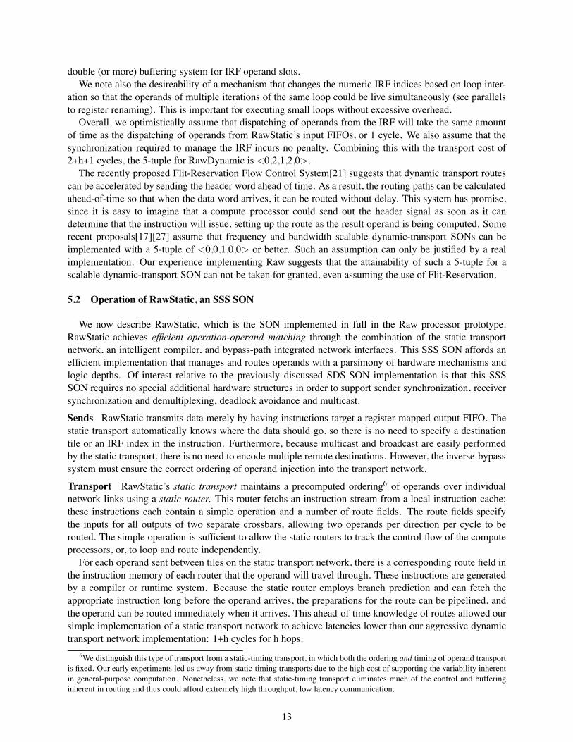
6 Implementation of the Raw Microprocessor
Figure 8. A die photo of the 16-tile Raw chip.The tiles and RAMs are easy to spot. A tile is4 mm x 4 mm.
ALU.S
ALU.M
CTRS
Static Router (SR)
Fetch Unit
SR Control
SR Crossbar #2
SR Crossbar #1
Compute Processor
Data Cache
Event
Compute Processor
Fetch Unit
MULT FPU
SPRs
CONTROL
BYPASS NET IN-FIFOS
R
F
DN #1 Crossbar
DN #1 Control
DN #2 Crossbar
DN #2 Control
ALU.C
INT
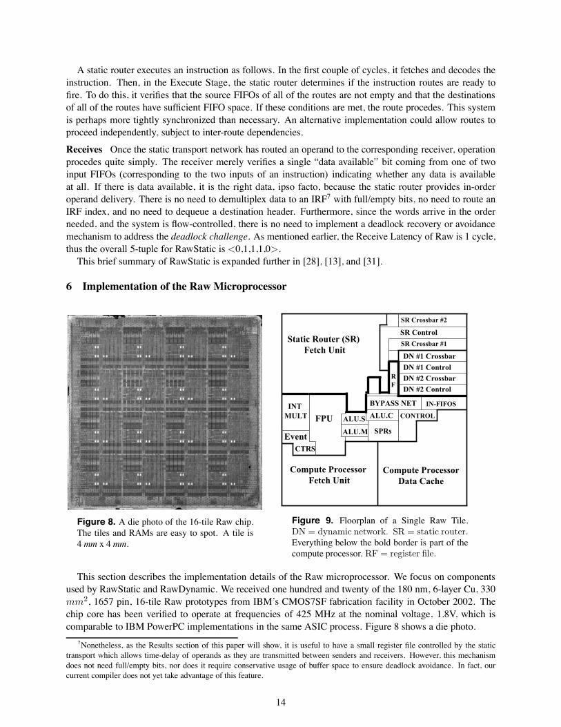
Figure 9. Floorplan of a Single Raw Tile.DN = dynamic network. SR = static router.Everything below the bold border is part of thecompute processor. RF = register file.
This section describes the implementation details of the Raw microprocessor. We focus on componentsused by RawStatic and RawDynamic. We received one hundred and twenty of the 180 nm, 6-layer Cu, 330mm2, 1657 pin, 16-tile Raw prototypes from IBM’s CMOS7SF fabrication facility in October 2002. Thechip core has been verified to operate at frequencies of 425 MHz at the nominal voltage, 1.8V, which iscomparable to IBM PowerPC implementations in the same ASIC process. Figure 8 shows a die photo.
7Nonetheless, as the Results section of this paper will show, it is useful to have a small register file controlled by the statictransport which allows time-delay of operands as they are transmitted between senders and receivers. However, this mechanismdoes not need full/empty bits, nor does it require conservative usage of buffer space to ensure deadlock avoidance. In fact, ourcurrent compiler does not yet take advantage of this feature.
14
The Raw prototype divides the usable silicon area into an array of 16 tiles. A tile contains an 8-stage in-order single-issue MIPS-style compute processor, a 4-stage pipelined FPU, a 32 KB data cache, two types ofrouters – static and dynamic, and 96 KB of instruction cache. These tiles are connected to nearest neighborsusing 4 separate networks, two static and two dynamic. These networks consist of over 1024 wires per tile.
Physical Design The floorplan of a Raw tile is shown in Figure 9. Approximately 40% of the tile area isdedicated to the dynamic and static transports. The local bypass network is situated in the center of the tilebecause it serves as a clearing house for the inputs and outputs of most of the components. The distanceof a component from the bypass networks is an inverse measure of the timing criticality of the component.Components that have ample timing slack can afford to be placed further away and suffer greater wiredelay. Thus, we can see that the static network paths were among the least critical, while the single-cycleALU and dynamic network components were most critical. The Event Counters, FPU, and Integer Multiplywere placed “wherever they fit” and the corresponding paths were pipelined (increasing the latency of thosefunctional units) until they met the cycle time. Finally, the fetch units and data cache are constrained bythe sizes of the SRAMs they contain (occupying almost all of the logic area) and thus have little flexibilitybeyond ensuring that the non-RAM logic is gravitated towards the bypass paths.
Of particular interest are the relative sizes of the dynamic and static transport components, which areroughly equal in raw transport bandwidth. The crossbars of the two transports are of similar size. However,the static router has a fetch unit, for which there is no equivalent in the dynamic transport. We note that acomparison of transport area is not sufficient to compare the areas of two SONs. Specifically, a full dynamictransport SON like RawDynamic requires the addition of hardware structures beyond the transport, whichare not represented in the Raw floorplan. These structures must be weighed against the static router’s fetchunit8 in order to compare SON area. We estimate the area impact of these additional structures as follows.First, the IRF will occupy 8-12x more area than the existing Register File due to the number of ports (>=2W,2R) and increased register count (we estimate 128) necessary to implement deadlock avoidance. Second,the dynamic router must transport headers and IRF indices with the data words, which we estimate resultsin 50% wider paths in the crossbars in order to provide the same operand bandwidth (as opposed to rawbandwidth) and the same scalability (1024 tiles). Finally, a dynamic transport SON needs to encode one ormore destinations in the compute processor instructions themselves, the multiple destinations being used formulticast. Thus, the required compute processor fetch unit RAM size for a given miss ratio may double oreven triple, depending on the fanout that a given instruction can specify. The implementation of completebandwidth-scalable dynamic transport SONs will shed more light on this subject.
Energy Characteristics of SONs By measuring the current used by the 16-tile Raw core using an ammeter,we were able to derive a number of statistics for the use of Raw’s transport networks. First, the statictransport is around 40% more power efficient than the dynamic transport for single word transfers (suchas found in SONs), but the dynamic network is almost twice as efficient for 31-word transfers. We foundthat there is a vast difference between the power of worst case usage (where every routing channel is beingused simultaneously), and typical usage. Worst case usage totals 38W @ 425 MHz, consisting of 21% statictransport, 15% dynamic transport, 39% compute processors, and 28% clock. Typical usage is 17W @ 425MHz, with around 5-10% going to static transport, and 55% to clock. Our data indicates that clock-gatingat the root of the clock tree of each tile (in order to reduce the energy usage of the clock tree when tiles areunused) is an architectural necessity in these systems. More detail on these results can be found in [10]. Arecent paper examines power tradeoffs in on-chip networks[34].
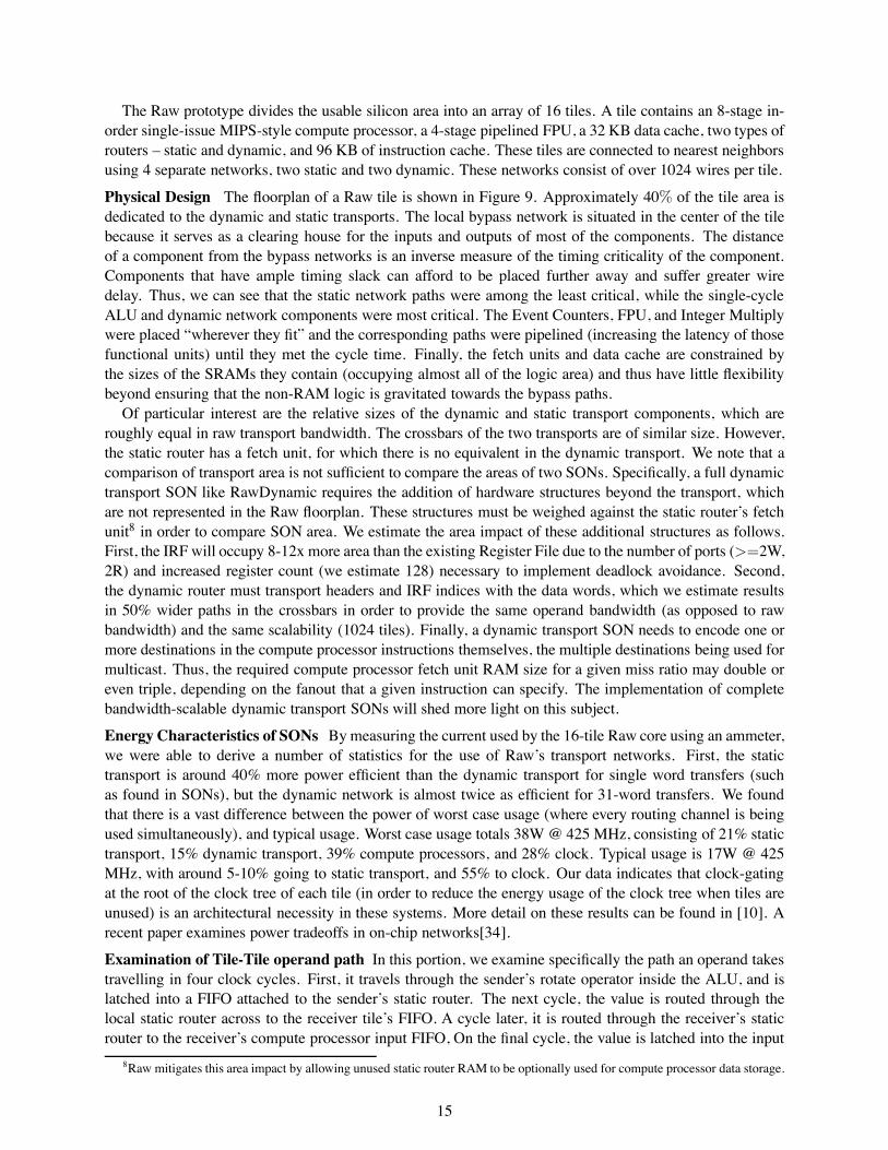
Examination of Tile-Tile operand path In this portion, we examine specifically the path an operand takestravelling in four clock cycles. First, it travels through the sender’s rotate operator inside the ALU, and islatched into a FIFO attached to the sender’s static router. The next cycle, the value is routed through thelocal static router across to the receiver tile’s FIFO. A cycle later, it is routed through the receiver’s staticrouter to the receiver’s compute processor input FIFO, On the final cycle, the value is latched into the input
8Raw mitigates this area impact by allowing unused static router RAM to be optionally used for compute processor data storage.
15
register of the receiver ALU. The total non-compute latency is thus three cycles.Figure 10 super-imposes the path taken by the operand on its journey, across two tiles. The white line is
the path the operand takes. The tick-marks on the line indicate the termination of a cycle. The floorplan inFigure 9 can be consulted to understand the path of travel.
The reference critical path of the Raw processor was designed to be the delay through a path in thecompute processor fetch unit. This path consists of an 8Kx32 bit SRAM and a 14-bit 2-input mux, theoutput routed back into the address input of the SRAM. All paths in the tile were optimized to be below thisdelay. This path times at approximately 3.4 ns, excluding register overhead.9 The total delay of a path mayvary from this number, because the register and clock skew overhead varies slightly. Furthermore, becausenone of the paths that an operand travels along are close to the cycle time of the chip, CAD optimizationslike buffering, gate reordering, and gate sizing may not have been run. As a result, some of the delays maybe greater than necessary. In the following tables, we examine the timing of signals travelling through themost critical paths of the operand route. We examine both the propagation of the actual operand data aswell as the single bit valid signal that interacts with the control logic to indicate that this data is a validtransmission. These are the key signals that are routed the full distance of an operand route.
Figure 10. The path of an operand route between two tiles.Path is superimposed over an EDA screenshot of the placedcells. Darker cells are collections of single-bit registers.
This process is somewhat compli-cated by the fact that a given signal maynot be on the direct critical path. For in-stance, it may arrive at the destinationgate earlier than the other inputs to thegate. In this case, it may appear as ifthe gate has greater delay than it reallydoes, because the input-to-output timeincludes the time that the gate is waitingfor the other inputs.
We address this issue as follows: first,for each cycle of each signal (data andvalid), we give the output slack and theinput slack. The input slack is the truemeasure of how much later the input sig-nal could have arrived, without any mod-ification to the circuit, without impacting the cycle time of the processor. The output slack measures howmuch earlier the output signal is latched into the flip-flop ending the cycle than is needed for the given cycletime. These two numbers are not exclusive; one cannot simply state the amount of simultaneous outputand input slack that could be exploited without examining the full path of gates between input and output.However, for our purposes, one useful statement can be made – that is, that the output slack of one stage andthe input slack of the next stage can be combined in order to eliminate a register, if the sum of the slacksis greater than or equal to the cycle time. The elimination of such a register on this path would cause areduction in the communication latency and thus in the 5-tuple.
Cycle 1 2 3 4Path Local ALU Local Router Remote Router Remote DispatchSlack Type Input Output Input Output Input Output Input OutputData (32b) 0 .44 1.01 1.44 1.34 1.86 1.82 .34Valid (1b) 0 1.90 .42 1.24 .46 1.20 1.23 .094
Of interest in the table to theright are Cycles 3 and 4, whereconsiderable adjacent Output andInput slack exists, on the DataSignal, totaling 3.68 ns, and onthe Valid signal, totaling 2.4 ns. The Data signal is already fast enough to remove the register. However, theValid signal requires an additional 1 ns of slack. With some optimization, it seems likely that one cycle of
9IBM requires tapeout on worst-case rather than nominal process corners. Because of this, the numbers are pessimistic relativeto the actual frequency (425 MHz) of average parts produced from the fab and used in typical conditions. All numbers given hereare worst-case numbers, and are extracted using CAD tools with parasitics from the actual wiring of the chip.
16
latency could be removed from the 5-tuple; reducing Raw’s 5-tuple to <0,1,1,0,0>. Two possibilities are:1) ANDing the Valid line later on into its consuming circuit, the stall calculation of the compute processorin cycle 4, or 2) adjusting the static router to begin processing the Valid signals (and thus most of the controllogic for a route) a half cycle earlier, taking advantage of the early arrival (2.3 ns) of the Valid signal intoCycle 2. However, because the static router can branch based on data values being routed on the processor,there may be a branch penalty for receiving, from the static router’s perspective, “late” data.
It is not altogether suprising that the control, including the Valid signal, is the bottleneck. In our experi-ences implementing multiple versions of both dynamic and static on-chip transport networks, the data pathsare always less critical than the corresponding control paths, to the extent that the Data path can almost beignored. Furthermore, it is easy to underestimate the number of logic levels required after the Valid and Datasignals are already sent out towards the destination tile – there are FIFOs to be dequeued, “space available”registers to be updated, and any other logic required to get the routers ready for the next route.
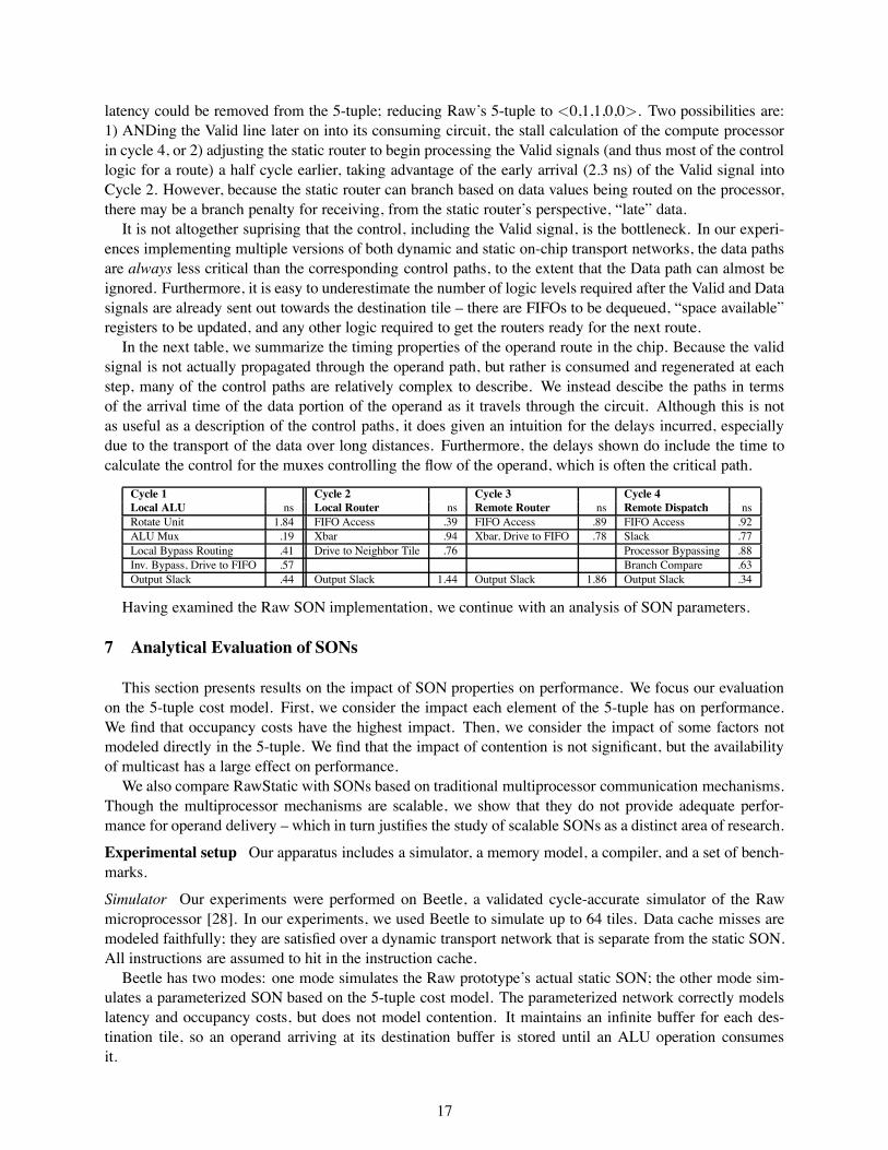
In the next table, we summarize the timing properties of the operand route in the chip. Because the validsignal is not actually propagated through the operand path, but rather is consumed and regenerated at eachstep, many of the control paths are relatively complex to describe. We instead descibe the paths in termsof the arrival time of the data portion of the operand as it travels through the circuit. Although this is notas useful as a description of the control paths, it does given an intuition for the delays incurred, especiallydue to the transport of the data over long distances. Furthermore, the delays shown do include the time tocalculate the control for the muxes controlling the flow of the operand, which is often the critical path.
Cycle 1 Cycle 2 Cycle 3 Cycle 4Local ALU ns Local Router ns Remote Router ns Remote Dispatch nsRotate Unit 1.84 FIFO Access .39 FIFO Access .89 FIFO Access .92ALU Mux .19 Xbar .94 Xbar, Drive to FIFO .78 Slack .77Local Bypass Routing .41 Drive to Neighbor Tile .76 Processor Bypassing .88Inv. Bypass, Drive to FIFO .57 Branch Compare .63Output Slack .44 Output Slack 1.44 Output Slack 1.86 Output Slack .34
Having examined the Raw SON implementation, we continue with an analysis of SON parameters.
7 Analytical Evaluation of SONs
This section presents results on the impact of SON properties on performance. We focus our evaluationon the 5-tuple cost model. First, we consider the impact each element of the 5-tuple has on performance.We find that occupancy costs have the highest impact. Then, we consider the impact of some factors notmodeled directly in the 5-tuple. We find that the impact of contention is not significant, but the availabilityof multicast has a large effect on performance.
We also compare RawStatic with SONs based on traditional multiprocessor communication mechanisms.Though the multiprocessor mechanisms are scalable, we show that they do not provide adequate perfor-mance for operand delivery – which in turn justifies the study of scalable SONs as a distinct area of research.
Experimental setup Our apparatus includes a simulator, a memory model, a compiler, and a set of bench-marks.
Simulator Our experiments were performed on Beetle, a validated cycle-accurate simulator of the Rawmicroprocessor [28]. In our experiments, we used Beetle to simulate up to 64 tiles. Data cache misses aremodeled faithfully; they are satisfied over a dynamic transport network that is separate from the static SON.All instructions are assumed to hit in the instruction cache.
Beetle has two modes: one mode simulates the Raw prototype’s actual static SON; the other mode sim-ulates a parameterized SON based on the 5-tuple cost model. The parameterized network correctly modelslatency and occupancy costs, but does not model contention. It maintains an infinite buffer for each des-tination tile, so an operand arriving at its destination buffer is stored until an ALU operation consumesit.
17
Memory model The Raw compiler maps each piece of program data to a specific home tile. This home tilebecomes the tile that is responsible for caching the data on chip. The distribution of data to tiles is providedby Maps, Raw’s compiler managed memory system [4, 12]. Using compiler analysis, Maps attempts toselect a distribution that guarantees that any load or store refers to data assigned to exactly one home tile.Dense matrix arrays, for example, usually get distributed element-wise across the tiles. The predictabilityof the accesses allows memory values to be forwarded from the caches of the home tiles to other tiles viaSON.
Compiler Code is generated by Rawcc, the Raw parallelizing compiler [13]. Rawcc takes sequential C orFortran programs and schedules their ILP across the Raw tiles. Rawcc operates on individual schedulingregions, each of which is a single-entry, single-exit control flow region. The mapping of code to Raw tilesincludes the following tasks: assigning instructions to tiles, scheduling the instructions on each tile, andmanaging the delivery of operands.
Before scheduling, Rawcc performs unrolling for two reasons. First, it unrolls to expose more parallelism.Second, unrolling is performed in conjunction with Maps to allow the compiler to distribute arrays, while atthe same time keeping the accesses to those arrays predictable.
To make intelligent instruction assignment and scheduling decisions, Rawcc models the communicationcosts of the target network accurately. Maps, however, is currently insensitive to the latency of the SONwhile performing memory placement (although the compiler does attempt to place operations close to thememory banks they access). Therefore, when dense matrix arrays are distributed, they are always distributedacross all the tiles. As communication cost increases, it may be better for the arrays to be distributed acrossfewer tiles, but our experiments do not vary this parameter.
Rawcc’s compilation strategy seeks to minimize the latency of operand transport on critical paths of thecomputation. Accordingly, it performs operation assignment in a way that gravitates sections of those criticalpaths to a single node so that that node’s 0-cycle local bypass network can be used, minimizing latency.
Benchmarks Table 1 lists out benchmarks. Btrix, Cholesky, and Mxm, Vpenta are from Nasa7 of Spec92.Tomcatv and Swim are from Spec95. Fpppp-kernel consumes 50% of the run-time of Spec95’s Fpppp.Sha and Aes implement the Secure Hash Algorithm and the Advanced Encryption Standard, respectively.Adpcm is from Mediabench. Jacobi and Life are from the Raw benchmark suite [3]. Fpppp-kernel, Sha andAes are irregular codes, Moldyn and Unstructured are sparse matrix codes, while the rest are dense matrixcodes. The problem sizes of the dense matrix applications have been reduced to cut down on simulation time.To improve parallelism via unrolled loop iterations, we manually applied an array reshape transformation toCholesky, and a loop fusion transformation to Mxm. Both transformations can be automated.
Impact of each 5-tuple parameter on performance We evaluated the impact of each 5-tuple parameteron performance. We used the Raw static transport SON as the baseline for comparison, and we recorded theperformance as we varied each individual 5-tuple parameter.
2 4 8 16 32 64
Sha 1.1 1.8 1.8 2.0 2.4 2.4Aes 1.9 2.9 3.0 3.6 3.2 3.8Fpppp-kernel 1.5 3.2 5.9 6.6 7.5 7.6Adpcm 0.8 1.2 1.4 1.4 1.2 0.9Unstructured 1.5 2.5 2.6 2.5 1.9 1.7Moldyn 1.2 1.7 1.7 1.6 1.0 0.9Btrix 1.6 4.8 11.7 24.5 46.1 xxxxCholesky 1.9 4.3 7.3 8.4 9.2 9.1Vpenta 1.6 4.9 11.0 24.1 49.2 81.4Mxm 1.8 4.2 7.1 9.3 10.6 11.9Tomcatv 1.2 2.9 5.0 7.8 9.0 xxxxSwim 1.0 2.1 4.2 8.1 16.5 24.3Jacobi 2.1 4.3 9.5 18.6 36.1 62.1Life 0.9 2.5 5.4 10.8 21.9 48.7
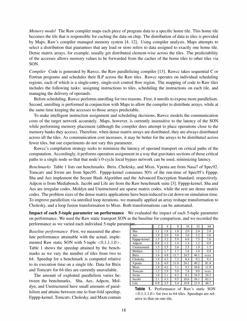
Table 1. Performance of Raw’s static SON<0,1,1,1,0> for two to 64 tiles. Speedups are rel-ative to that on one tile.
Baseline performance First, we measured the abso-lute performance attainable with the actual, imple-mented Raw static SON with 5-tuple <0,1,1,1,0>.Table 1 shows the speedup attained by the bench-marks as we vary the number of tiles from two to64. Speedup for a benchmark is computed relativeto its execution time on a single tile. Data for Btrixand Tomcatv for 64 tiles are currently unavailable.
The amount of exploited parallelism varies be-tween the benchmarks. Sha, Aes, Adpcm, Mol-dyn, and Unstructured have small amounts of paral-lelism and attains between one to four-fold speedup.Fpppp-kernel, Tomcatv, Cholesky, and Mxm contain
18
modest amounts of parallelism and attain seven to12-fold speedup, respectively. The remaining benchmarks (Btrix, Vpenta, Swim, Jacobi, and Life) haveenough parallelism for the speedup to scale well up to 64 tiles, with speedups ranging from 20 up to 80.Note that speedup can be superlinear due to effects from increased cache capacity as we scale the numberof tiles. The presence of sizable speedup validates our experimental setup for the study of SONs – withoutsuch speedups, it would be moot to explore SONs that are scalable.
The parallelism scalability of the benchmarks can roughly divided into two classes. Most of the densematrix codes, including Btrix, Vpenta, Mxm, Swim, Jacobi, and Life are able to continually gain perfor-mance with increasing number of tiles. For others, the speedups eventually tail off, with 16 tiles being themost frequent point where the performance peaks.
Send occupancy (cycles)0 4 8 12 16
Spe
edup
0
0.1
0.2
0.3
0.4
0.5
0.6
0.7
0.8
0.9
1
1.1
shaaesfppppadpcmunstructmoldyn
choleskyvpentamxmswimjacobilife
Figure 11. Effect of send occupancy on performanceon 64 tiles, i.e., <n,1,1,1,0>.
Receive occupancy (cycles)0 4 8 12 16
Spe
edup
0
0.1
0.2
0.3
0.4
0.5
0.6
0.7
0.8
0.9
1
1.1
shaaesfppppadpcmunstructmoldyn
choleskyvpentamxmswimjacobilife
Figure 12. Effect of receive occupancy on perfor-mance on 64 tiles, i.e., <0,1,1,1,n>.
Send and receive occupancies Next, we measured the effects of send and receive occupancies on perfor-mance. We emphasize that these occupancies are visible to the compiler so that it can account for them asbest as it can when it schedules ILP. Figures 11 and 12 graph these effects. All data points are based on 64tiles. Performance is normalized to that of the actual Raw static SON with 5-tuple <0,1,1,1,0>.
The trends of the two occupancy curves are similar. Overall, results indicate that occupancy impacts per-formance significantly. Performance drops by as much as 20% even when the send occupancy is increasedfrom zero to one cycle. As expected, the incremental impact of additional cycles of occupancy is less severe.
The slope of each curve is primarily a function of the amount communication and the amount of slack inthe schedule. Benchmarks that don’t communicate a lot and have a large number of cache misses, such asVpenta, have higher slacks and are able to better tolerate increase in send occupancies. Benchmarks withfine-grained parallelism such as Sha and Fpppp-kernel have much lower tolerance for high occupancies.
It is clear from these results that SONs should implement zero cycle send and receive occupancy.
Send and receive latencies We switched to the parameterized SON to measure the effects of send andreceive latencies on performance. For this experiment, we set the network hop latency to zero, with 5-tuple<0,n,0,0,0> or <0,0,0,n,0>. Due to simulator constraints, the minimum latency we can simulate is one.Note that because the parameterized network does not model contention, the effect of n cycles of sendlatency is the same as the effect of n cycles of receive latency, so we need not collect data for both. Also,note that each of these 5-tuples also happens to represent an n cycle contention-free crossbar.
Send/receive latency (cycles)0 4 8 12 16 20 24 28 32 36 40 44 48 52 56 60 64
Spe
edup
−0.2
0
0.2
0.4
0.6
0.8
1
1.2
1.4
1.6
shaaesfppppadpcmunstructmoldyn
choleskyvpentamxmswimjacobilife
Figure 13 Effects of send or receive latencies
Figure 13 graphs these latency effects on per-formance on 64 tiles. A speedup of 1.0 repre-sents the performance of the Raw SSS SON with5-tuple <0,1,1,1,0>.
Intuitively, we expect benchmark sensitivityto latency to depend on the granularity of avail-able parallelism. The finer the grain of paral-lelism, the more sensitive the benchmark is to
19
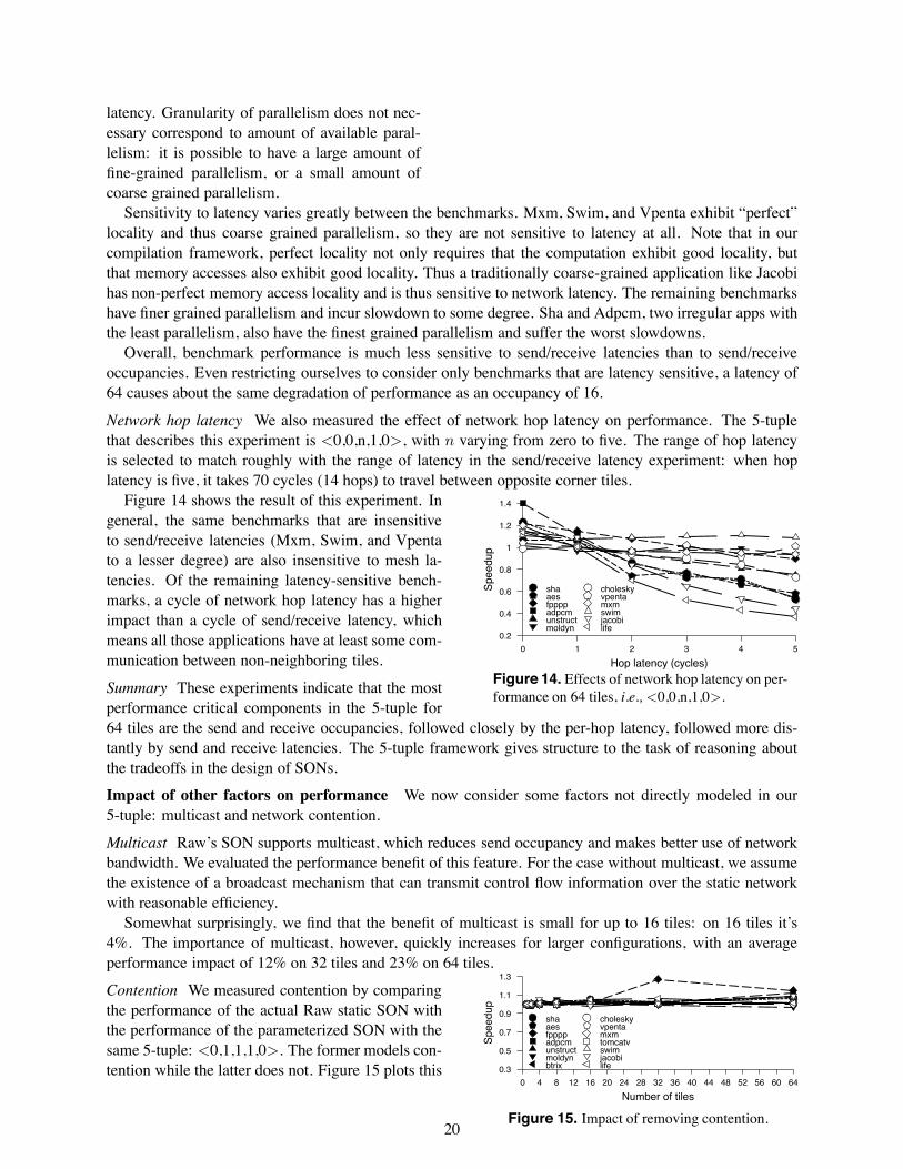
latency. Granularity of parallelism does not nec-essary correspond to amount of available paral-lelism: it is possible to have a large amount offine-grained parallelism, or a small amount ofcoarse grained parallelism.
Sensitivity to latency varies greatly between the benchmarks. Mxm, Swim, and Vpenta exhibit “perfect”locality and thus coarse grained parallelism, so they are not sensitive to latency at all. Note that in ourcompilation framework, perfect locality not only requires that the computation exhibit good locality, butthat memory accesses also exhibit good locality. Thus a traditionally coarse-grained application like Jacobihas non-perfect memory access locality and is thus sensitive to network latency. The remaining benchmarkshave finer grained parallelism and incur slowdown to some degree. Sha and Adpcm, two irregular apps withthe least parallelism, also have the finest grained parallelism and suffer the worst slowdowns.
Overall, benchmark performance is much less sensitive to send/receive latencies than to send/receiveoccupancies. Even restricting ourselves to consider only benchmarks that are latency sensitive, a latency of64 causes about the same degradation of performance as an occupancy of 16.
Network hop latency We also measured the effect of network hop latency on performance. The 5-tuplethat describes this experiment is <0,0,n,1,0>, with n varying from zero to five. The range of hop latencyis selected to match roughly with the range of latency in the send/receive latency experiment: when hoplatency is five, it takes 70 cycles (14 hops) to travel between opposite corner tiles.
Hop latency (cycles)0 1 2 3 4 5
Spe
edup
0.2
0.4
0.6
0.8
1
1.2
1.4
shaaesfppppadpcmunstructmoldyn
choleskyvpentamxmswimjacobilife
Figure 14. Effects of network hop latency on per-formance on 64 tiles, i.e., <0,0,n,1,0>.
Figure 14 shows the result of this experiment. Ingeneral, the same benchmarks that are insensitiveto send/receive latencies (Mxm, Swim, and Vpentato a lesser degree) are also insensitive to mesh la-tencies. Of the remaining latency-sensitive bench-marks, a cycle of network hop latency has a higherimpact than a cycle of send/receive latency, whichmeans all those applications have at least some com-munication between non-neighboring tiles.
Summary These experiments indicate that the mostperformance critical components in the 5-tuple for64 tiles are the send and receive occupancies, followed closely by the per-hop latency, followed more dis-tantly by send and receive latencies. The 5-tuple framework gives structure to the task of reasoning aboutthe tradeoffs in the design of SONs.
Impact of other factors on performance We now consider some factors not directly modeled in our5-tuple: multicast and network contention.
Multicast Raw’s SON supports multicast, which reduces send occupancy and makes better use of networkbandwidth. We evaluated the performance benefit of this feature. For the case without multicast, we assumethe existence of a broadcast mechanism that can transmit control flow information over the static networkwith reasonable efficiency.
Somewhat surprisingly, we find that the benefit of multicast is small for up to 16 tiles: on 16 tiles it’s4%. The importance of multicast, however, quickly increases for larger configurations, with an averageperformance impact of 12% on 32 tiles and 23% on 64 tiles.
Number of tiles0 4 8 12 16 20 24 28 32 36 40 44 48 52 56 60 64
Spe
edup
0.3
0.5
0.7
0.9
1.1
1.3
shaaesfppppadpcmunstructmoldynbtrix
choleskyvpentamxmtomcatvswimjacobilife
Figure 15. Impact of removing contention.
Contention We measured contention by comparingthe performance of the actual Raw static SON withthe performance of the parameterized SON with thesame 5-tuple: <0,1,1,1,0>. The former models con-tention while the latter does not. Figure 15 plots this
20
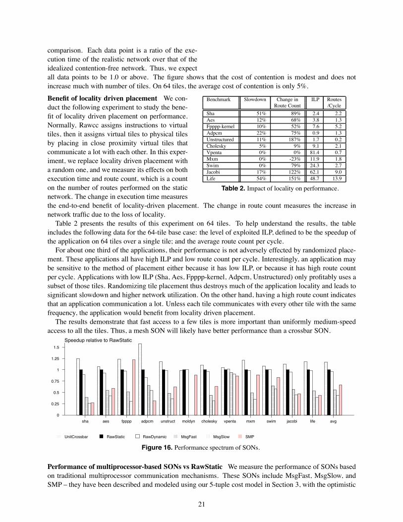
comparison. Each data point is a ratio of the exe-cution time of the realistic network over that of theidealized contention-free network. Thus, we expectall data points to be 1.0 or above. The figure shows that the cost of contention is modest and does notincrease much with number of tiles. On 64 tiles, the average cost of contention is only 5%.
Benchmark Slowdown Change in ILP RoutesRoute Count /Cycle
Sha 51% 89% 2.4 2.2Aes 12% 68% 3.8 1.3Fpppp-kernel 10% 52% 7.6 5.2Adpcm 22% 75% 0.9 1.3Unstructured 11% 187% 1.7 0.2Cholesky 5% 9% 9.1 2.1Vpenta 0% 0% 81.4 0.7Mxm 0% -23% 11.9 1.8Swim 0% 79% 24.3 2.7Jacobi 17% 122% 62.1 9.0Life 54% 151% 48.7 13.9
Table 2. Impact of locality on performance.
Benefit of locality driven placement We con-duct the following experiment to study the bene-fit of locality driven placement on performance.Normally, Rawcc assigns instructions to virtualtiles, then it assigns virtual tiles to physical tilesby placing in close proximity virtual tiles thatcommunicate a lot with each other. In this exper-iment, we replace locality driven placement witha random one, and we measure its effects on bothexecution time and route count, which is a counton the number of routes performed on the staticnetwork. The change in execution time measuresthe end-to-end benefit of locality-driven placement. The change in route count measures the increase innetwork traffic due to the loss of locality.
Table 2 presents the results of this experiment on 64 tiles. To help understand the results, the tableincludes the following data for the 64-tile base case: the level of exploited ILP, defined to be the speedup ofthe application on 64 tiles over a single tile; and the average route count per cycle.
For about one third of the applications, their performance is not adversely effected by randomized place-ment. These applications all have high ILP and low route count per cycle. Interestingly, an application maybe sensitive to the method of placement either because it has low ILP, or because it has high route countper cycle. Applications with low ILP (Sha, Aes, Fpppp-kernel, Adpcm, Unstructured) only profitably uses asubset of those tiles. Randomizing tile placement thus destroys much of the application locality and leads tosignificant slowdown and higher network utilization. On the other hand, having a high route count indicatesthat an application communication a lot. Unless each tile communicates with every other tile with the samefrequency, the application would benefit from locality driven placement.
The results demonstrate that fast access to a few tiles is more important than uniformly medium-speedaccess to all the tiles. Thus, a mesh SON will likely have better performance than a crossbar SON.
Speedup relative to RawStatic
sha aes fpppp adpcm unstruct moldyn cholesky vpenta mxm swim jacobi life avg
0
0.25
0.5
0.75
1
1.25
1.5
UnitCrossbar RawStatic RawDynamic MsgFast MsgSlow SMP
Figure 16. Performance spectrum of SONs.
Performance of multiprocessor-based SONs vs RawStatic We measure the performance of SONs basedon traditional multiprocessor communication mechanisms. These SONs include MsgFast, MsgSlow, andSMP – they have been described and modeled using our 5-tuple cost model in Section 3, with the optimistic
21
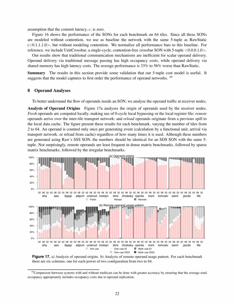
assumption that the commit latency, c, is zero.Figure 16 shows the performance of the SONs for each benchmark on 64 tiles. Since all these SONs
are modeled without contention, we use as baseline the network with the same 5-tuple as RawStatic(<0,1,1,1,0>, but without modeling contention. We normalize all performance bars to this baseline. Forreference, we include UnitCrossbar, a single-cycle, contention-free crossbar SON with 5-tuple <0,0,0,1,0>.
Our results show that traditional communication mechanisms are inefficient for scalar operand delivery.Operand delivery via traditional message passing has high occupancy costs, while operand delivery viashared memory has high latency costs. The average performance is 33% to 56% worse than RawStatic.
Summary The results in this section provide some validation that our 5-tuple cost model is useful. Itsuggests that the model captures to first order the performance of operand networks. 10
8 Operand Analyses
To better understand the flow of operands inside an SON, we analyse the operand traffic at receiver nodes.
Analysis of Operand Origins Figure 17a analyses the origin of operands used by the receiver nodes.Fresh operands are computed locally, making use of 0-cycle local bypassing or the local register file; remoteoperands arrive over the inter-tile transport network; and reload operands originate from a previous spill tothe local data cache. The figure present these results for each benchmark, varying the number of tiles from2 to 64. An operand is counted only once per generating event (calculation by a functional unit, arrival viatransport network, or reload from cache) regardless of how many times it is used. Although these numbersare generated using Raw’s SSS SON, the numbers should be identical for an SDS SON with the same 5-tuple. Not surprisingly, remote operands are least frequent in dense matrix benchmarks, followed by sparsematrix benchmarks, followed by the irregular benchmarks.
(a) Operand origins
Fresh Reload Remote
02 08 32 02 08 32 02 08 32 02 08 32 02 08 32 02 08 32 02 08 32 02 08 32 02 08 32 02 08 32 02 08 32 02 08 32 02 08 32 02 08 32
sha aes fpppp adpcm unstruct moldyn btrix cholesky vpenta mxm tomcatv swim jacobi life
0%
20%
40%
60%
80%
100%
(b) Remote operand usage pattern
Hot−use One−use IO
One−use OOO
Multi−use IO
Multi−use OOO
02 08 32 02 08 32 02 08 32 02 08 32 02 08 32 02 08 32 02 08 32 02 08 32 02 08 32 02 08 32 02 08 32 02 08 32 02 08 32 02 08 32
sha aes fpppp adpcm unstruct moldyn btrix cholesky vpenta mxm tomcatv swim jacobi life
0%
20%
40%
60%
80%
100%
Figure 17. a) Analysis of operand origins. b) Analysis of remote operand usage pattern. For each benchmarkthere are six columns, one for each power of two configuration from two to 64.
10Comparison between systems with and without multicast can be done with greater accuracy by ensuring that the average sendoccupancy appropriately includes occupancy costs due to operand replication.
22
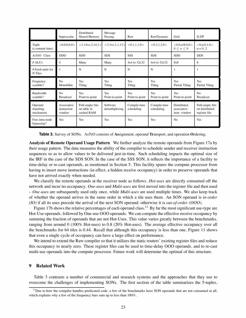
Distributed MessageSuperscalar Shared Memory Passing Raw RawDynamic Grid ILDP
Tuple <0,0,0,0,0> <1,14+c,2,14,1> <3,3+c,1,1,12> <0,1,1,1,0> <0,2,1,2,0> <0,0,n/8,0,0> <0,n,0,1,0>(c:commit time) 0 ≤ n ≤ 8 n = 0, 2
AsTrO Class DDD SDD SDS SSS SDS SDD DDS
# ALUs 4 Many Many 4x4 to 32x32 4x4 to 32x32 8x8 8
# Fetch units for 1 N N N N 1 1N Tiles
Frequency No Yes Yes Yes Yes Yes Yesscalable? Monolithic Tiling Tiling Tiling Tiling Partial Tiling Partial Tiling
Bandwidth No Yes Yes Yes Yes Yes Noscalable? Broadcast Point-to-point Point-to-point Point-to-point Point-to-point Point-to-point Broadcast
Operand Associative Full-empty bits Software Compile-time Compile-time Distributed, Full-empty bitsmatching instruction on table in demultiplexing scheduling scheduling associative on distributedmechanism window cached RAM instr. window register file
Free intra-node Yes Yes Yes Yes Yes No Yesbypassing?
Table 3. Survey of SONs. AsTrO consists of Assignment, operand Transport, and operationOrdering.
Analysis of Remote Operand Usage Pattern We further analyze the remote operands from Figure 17a bytheir usage pattern. The data measures the ability of the compiler to schedule sender and receiver instructionsequences so as to allow values to be delivered just-in-time. Such scheduling impacts the optimal size ofthe IRF in the case of the SDS SON. In the case of the SSS SON, it reflects the importance of a facility totime-delay or re-cast operands, as mentioned in Section 5. This facility spares the compute processor fromhaving to insert move instructions (in effect, a hidden receive occupancy) in order to preserve operands thathave not arrived exactly when needed.
We classify the remote operands at the receiver node as follows. Hot-uses are directly consumed off thenetwork and incur no occupancy. One-uses and Multi-uses are first moved into the register file and then used– One-uses are subsequently used only once, while Multi-uses are used multiple times. We also keep trackof whether the operand arrives in the same order in which a tile uses them. An SON operand is in-order(IO) if all its uses precede the arrival of the next SON operand; otherwise it is out-of-order (OOO).
Figure 17b shows the relative percentages of each operand class.11 By far the most significant use-type areHot-Use operands, followed by One-use OOO operands. We can compute the effective receive occupancy bysumming the fraction of operands that are not Hot-Uses. This value varies greatly between the benchmarks,ranging from around 0 (100% Hot-uses) to 0.8 (20% Hot-uses). The average effective occupancy over allthe benchmarks for 64 tiles is 0.44. Recall that although this occupancy is less than one, Figure 11 showsthat even a single cycle of occupancy can have a large effect on performance.
We intend to extend the Raw compiler so that it utilizes the static routers’ existing register files and reducethis occupancy to nearly zero. These register files can be used to time-delay OOO operands, and to re-castmulti-use operands into the compute processor. Future work will determine the optimal of this structure.
9 Related Work
Table 3 contrasts a number of commercial and research systems and the approaches that they use toovercome the challenges of implementing SONs. The first section of the table summarizes the 5-tuples,
11Due to how the compiler handles predicated code, a few of the benchmarks have SON operands that are not consumed at all,which explains why a few of the frequency bars sum up to less than 100%.
23
the AsTrO category, and the number of ALUs and fetch units supported in each of the SONs. Note thatthe ILDP and Grid papers examine a range of estimated costs; more information on the actual costs will beforthcoming when those systems are implemented.
The second, third, and fourth super-rows give the way in which the various designs address the frequencyscalability, bandwidth scalability, and operation-operand matching challenges, respectively. All recent pro-cessors use tiling to achieve frequency scalability. Bandwidth scalable designs use point-to-point SONs toreplace indiscriminant broadcasts with multicasts. So far, all of the bandwidth scalable architectures usestatic assignment of operations to nodes. The diversity of approaches is richest in the category of operandmatching mechanisms, and in the selection of network transports. Specifically, the choice of static versusdynamic transport results in very different implementations. However, there is a common belief that the fivetuples of both can be designed to be very small. Finally, a common theme is the use of intra-tile bypassingto cut down significantly on latency and required network bandwidth.
The solutions to the deadlock and exceptions challenges are not listed because they vary between imple-mentations of superscalars, distributed shared memory machines and message passing machines, and theyare not specified in full detail in Grid and ILDP papers.
This paper extends an earlier framework for operand networks that was given in [30], and expands uponthe work described in [29].
10 Conclusions
As we approach the scaling limits of wide-issue superscalar processors, researchers are seeking alterna-tives that are based on partitioned microprocessor architectures. Partitioned architectures distribute ALUsand register files over scalar operand networks (SONs) that must somehow account for communication la-tencies. Even though the microarchitectures are distributed, ILP can be exploited on these SONs becausetheir latencies are extremely low.
This paper makes several contributions: it introduces the notion of SONs and discusses the challenges inimplementing scalable forms of these networks. The challenges include maintaining high frequencies, deal-ing with limited bandwidth related to scalable networks, implementing ultra-low cost operation-operandmatching, avoiding deadlock and starvation, and achieving correct operation in the face of exceptionalevents. The paper looks at several recently proposed distributed architectures that exploit ILP and discusseshow each addresses the challenges, using a new AsTrO taxonomy to distinguish between their logical prop-erties. This paper also describes two SON designs in the context of the Raw microprocessor and discusseshow the implementations deal with each of the challenges in scaling SONs.
This paper breaks down the latency of operand transport into five components <SO, SL, NHL, RL,RO>: send occupancy, send latency, network hop latency, receive latency, and receive occupancy. Thepaper evaluates several families of SONs based on this 5-tuple. Our early results show that send and receiveoccupancies have the biggest impact on performance. For our benchmarks, performance decreases by up to20 percent even if the occupancy on the send or receive side increases by just 1 cycle. The per-hop latencyfollows closely behind in importance. Hardware support for multicast has a high impact on performance forlarge systems. Other parameters such as send/receive latencies and network contention have smaller impact.
In the past, the design of SONs was closely tied in with the design of other mechanisms in a microproces-sor – for example, register files and bypassing. In this paper, we attempt to carve out the generalized SONas an independent architectural entity that merits its own research. We believe that research focused on thescalar operand network will yield significant simplifications in future scalable ILP processors.
Avenues for further research on scalar operand networks are plentiful, and relate to both a re-evaluationof existing network concepts in the scalar operand space, and the discovery of new SON mechanisms. Apartial list includes: (1) Designing SONs for a high clock rate while minimizing the 5-tuple parameters, (2)evaluating the performance for much larger numbers of tiles and a wider set of programs, (3) generalizingSONs so that they support other forms of parallelism such as stream and thread parallelism in SMT-styleprocessing, (4) exploration of both dynamic and static schemes for assignment, transport and ordering, (5)
24
mechanisms for fast exception handling and context switching, (6) analysis of the tradeoffs between commitpoint, exception handling, and send latency, (7) low energy SONs, and (8) techniques for deadlock avoidanceand recovery in SONs.
Acknowledgments Raw is funded by Darpa, NSF, ITRI and the Oxygen Alliance.
References
[1] AGARWAL, HRISHIKESH, KECKLER, AND BURGER. Clock Rate versus IPC: The End of the Road for Conventional Microarchitectures. InInternational Symposium on Computer Architecture (2000).
[2] ARVIND, AND BROBST. The Evolution of Dataflow Architectures from Static Dataflow to P-RISC. International Journal of High SpeedComputing 5, 2 (June 1993).
[3] BABB ET AL. The RAW Benchmark Suite: Computation Structures for General Purpose Computing. In IEEE Symposium on Field-Programmable Custom Computing Machines (1997).
[4] BARUA, LEE, AMARASINGHE, AND AGARWAL. Maps: A Compiler-Managed Memory System for Raw Machines. In International Sympo-sium on Computer Architecture (1999).
[5] DALLY. A VLSI Architecture for Concurrent Data Structures. Kluwer Academic Publishers, 1987.
[6] DUATO, AND PINKSTON. A General Theory for Deadlock-Free Adaptive Routing using a Mixed Set of Resources. IEEE Transactions onParallel and Distributed Systems 12, 12 (December 2001).
[7] GROSS, AND O’HALLORON. iWarp, Anatomy of a Parallel Computing System. The MIT Press, Cambridge, MA, 1998.
[8] JANSSEN, AND CORPORAAL. Partitioned Register File for TTAs. In International Symposium on Microarchitecture (1996).
[9] KIM, AND SMITH. An Instruction Set Architecture and Microarchitecture for Instruction Level Distributed Processing. In InternationalSymposium on Computer Architecture (2002).
[10] KIM, TAYLOR, MILLER, AND WENTZLAFF. Energy Characterization of a Tiled Architecture Processor with On-Chip Networks. In Interna-tional Symposium on Low Power Electronics and Design (2003).
[11] KUBIATOWICZ, AND AGARWAL. Anatomy of a Message in the Alewife Multiprocessor. In International Supercomputing Conference (1993).
[12] LARSEN, AND AMARASINGHE. Increasing and Detecting Memory Address Congruence. In International Conference on Parallel Architec-tures and Compilation Techniques (2002).
[13] LEE ET AL. Space-Time Scheduling of Instruction-Level Parallelism on a Raw Machine. In Conference on Architectural Support forProgramming Languages and Operating Systems (1998).
[14] MACKENZIE, KUBIATOWICZ, FRANK, LEE, LEE, AGARWAL, AND KAASHOEK. Exploiting Two-Case Delivery for Fast Protected Messag-ing. In HPCA (July 1997).
[15] MAI, PAASKE, JAYASENA, HO, DALLY, AND HOROWITZ. Smart Memories: A Modular Reconfigurable Architecture. In InternationalSymposium on Computer Architecture (2000).
[16] NAFFZIGER, AND HAMMOND. The Implementation of the Next-Generation 64b Itanium Microprocessor. In IEEE International Solid-StateCircuits Conference (2002).
[17] NAGARAJAN, SANKARALINGAM, BURGER, AND KECKLER. A Design Space Evaluation of Grid Processor Architectures. In InternationalSymposium on Microarchitecture (2001).
[18] PALACHARLA, JOUPPI, AND SMITH. Complexity-Effective Superscalar Processors. In International Symposium on Computer Architecture(1997).
[19] PANDA, SINGAL AND KESAVAN. Multidestination message passing in Wormhole k-ary n-cube Networks with Base Routing ConformedPaths. In IEEE Transactions on Parallel and Distributed Systems (1999).
[20] PARCERISA, SAHUQUILLO, GONZALEZ, AND DUATO. Efficient Interconnects for Clustered Microarchitectures. In International Conferenceon Parallel Architectures and Compilation Techniques (2002).
[21] PEH, AND DALLY. Flit-Reservation Flow Control. In International Symposium on High-Performance Computer Architecture (2000).
[22] SANKARALINGAM, SINGH, KECKLER, AND BURGER. Routed Inter-ALU Networks for ILP Scalability and Performance. In InternationalConference on Computer Design (2003).
[23] SEITZ, BODEN, SEIZOVIC, AND SU. The Design of the Caltech Mosaic C Multicomputer. In Research on Integrated Systems SymposiumProceedings (Cambridge, MA, 1993), MIT Press.
[24] SOHI, BREACH, AND VIJAYKUMAR. Multiscalar Processors. In International Symposium on Computer Architecture (1995).
[25] SONG, AND PINKSTON. A Progressive Approach to Handling Message Dependent Deadlocks in Parallel Computer Systems. IEEE Transac-tions on Parallel and Distributed Systems 14, 3 (March 2003).
[26] SULLIVAN, AND BASHKOW. A Large Scale, Homogeneous, Fully Distributed Parallel Machine. In 4th Annual Symposium on ComputerArchitecture (1977).
[27] SWANSON, MICHELSON, SCHWERIN, AND OSKIN. WaveScalar. In International Symposium on Microarchitecture (2003).
[28] TAYLOR. The Raw Processor Specification. ftp://ftp.cag.lcs.mit.edu/pub/raw/documents/RawSpec99.pdf.
25
[29] TAYLOR, LEE, AMARASINGHE, AND AGARWAL. Scalar Operand Networks: On-Chip Interconnect for ILP in Partitioned Architectures. InInternational Symposium on High Performance Computer Architecture (2003).
[30] TAYLOR ET AL. How to Build Scalable On-Chip ILP Networks for a Decentralized Architecture. Tech. Rep. 628, MIT, April 2000.
[31] TAYLOR ET AL. The Raw Microprocessor: A Computational Fabric for Software Circuits and General-Purpose Prgrams. IEEE Micro (March2002).
[32] VON EICKEN, CULLER, GOLDSTEIN, AND SCHAUSER. Active Messages: A Mechanism for Integrated Communication and Computation.In 19th International Symposium on Computer Architecture (May 1992).
[33] WAINGOLD ET AL. Baring It All to Software: Raw Machines. IEEE Computer 30, 9 (Sept. 1997).
[34] WANG, PEH AND MALIK. Power-Driven Design of Router Microarchitectures in On-Chip Networks. In International Symposium onMicroarchitecture (2003).
11 Supplemental Section: Shared Memory operation-operand matching
On a shared-memory multiprocessor, one could imagine implementing operation-operand matching byimplementing a large software-managed operand buffer in cache RAM. Each communication edge betweensender and receiver could be assigned a memory location that has a full/empty bit. In order to supportmultiple simultaneous dynamic instantiations of an edge when executing loops, a base register could beincremented on loop iteration. The sender processor would execute a special store instruction that stores theoutgoing value and sets the full/empty bit. The readers of a memory location would execute a special loadinstruction that blocks until the full/empty bit is set, then returns the written value. Every so often, all of theprocessors would synchronize so that they can reuse the operand buffer. A special mechanism could flip thesense of the full/empty bit so that the bits would not have to be cleared.
The send and receive occupancies of this approach are difficult to evaluate. The sender’s store instructionand receiver’s load instruction only occupy a single instruction slot; however, the processors may still incuran occupancy cost due to limitations on the number of outstanding loads and stores. The send latency isthe latency of a store instruction plus the commit latency. The receive latency includes the delay of the loadinstruction as well as the non-network time required for the cache protocols to process the receiver’s requestfor the line from the sender’s cache.
This approach has number of benefits: First, it supports multicast (although not in a way that savesbandwidth over multiple unicasts). Second, it allows a very large number of live operands due to the factthat the physical register file is being implemented in the cache. Finally, because the memory address iseffectively a tag for the value, no software instructions are required for demultiplexing. In [29], we estimatethe 5-tuple of this relatively aggressive shared-memory SON implementation to be <1,14+c,2,14,1>.
12 Supplemental Section: Systolic array operation-operand matching
Systolic machines like iWarp [7] were some of the first systems to achieve low-overhead operation-operand matching in large-scale systems. iWarp sported register-mapped communication, although it isoptimized for transmitting streams of data rather than individual scalar values. The programming model sup-ported a small number of pre-compiled communication patterns (no more than 20 communications streamscould pass through a single node). For the purposes of operation-operand matching, each stream corre-sponded to a logical connection between two nodes. Because values from different sources would arrive viadifferent logical streams and values sent from one source would be implicitly ordered, iWarp had efficientoperation-operand matching. It needed only execute an instruction to change the current input stream ifnecessary, and then use the appropriate register designator. Similarly, for sending, iWarp would optionallyhave to change the output stream and then write the value using the appropriate register designator. Un-fortunately, the iWarp system is limited in its ability to facilitate ILP communication by the hardware limiton the number of communication patterns, and by the relatively large cost of establishing new communi-cation channels. Thus, the iWarp model works well for stream-type bulk data transfers between sendersand receivers, but it is less suited to ILP communication. With ILP, large numbers of scalar data values
26

must be communicated with very low latency in irregular communication patterns. iWarp’s five-tuple canmodeled as <1,6,5,0,1> - one cycle of occupancy for sender stream change, six cycles to exit the node, fouror six cycles per hop, approximately 0 cycles receive latency, and 1 cycle of receive occupancy. An on-chipversion of iWarp would probably incur a smaller per-hop latency but a larger send latency because, like amultiprocessor, it must incur the commit latency cost before it releases data into the network.
27