scaling issues scalable multiprocessors
TRANSCRIPT

Scalable Multiprocessors
2
Topics
Scaling issuesSupporting programming modelsNetwork interfaceInterconnection networkConsiderations in Bluegene/L design
3
Limited Scaling of a Bus
Scaling limitClose coupling among components
Characteristic Bus
Physical Length ~ 1 ft
Number of Connections fixed
Maximum Bandwidth fixed
Interface to Comm. medium memory
Global Order arbitration
Protection Virtual ⇒ physical
Trust total
OS single
comm. abstraction HW
P1
$
Pn
$. . .
MEM I/O
4
Comparing with a LAN
No clear limit to physical scaling, little trust, no global order, consensus difficult to achieve.Independent failure and restart
Characteristic Bus LAN
Physical Length ~ 1 ft KM
Number of Connections fixed many
Maximum Bandwidth fixed ???
Interface to Comm. medium memory peripheral
Global Order arbitration ???
Protection Virtual ⇒ physical OS
Trust total little
OS single independent
comm. abstraction HW SW

5
Scalable Computers
What are the design trade-offs for the spectrum of machines between?
Specialize or commodity nodes?Capability of node-to-network interfaceSupporting programming models?
What does scalability mean?Avoid inherent design limits on resourcesBandwidth increases with nLatency does not increase with nCost increases slowly with n
6
Bandwidth Scalability
What fundamentally limits bandwidth?single set of wires
Must have many independent wiresConnect modules through switches
P M . . .P M P M
Bus
Xbar
Router
Switches
S S S. . .
7
Programming Models Realized by Protocols
CAD
Multiprogramming Sharedaddress
Messagepassing
Dataparallel
Database Scientific modeling Parallel applications
Programming models
Communication abstractionUser/system boundary
Compilationor library
Operating systems support
Communication hardware
Physical communication medium
Hardware/software boundary
Network Transactions
8
Network Transaction Primitive
one-way transfer of information from a source output buffer to a dest. input buffer
causes some action at the destinationoccurrence is not directly visible at source
deposit data, state change, reply
output buffer input buffer
Source Node Destination Node
Communication Network
° ° °
serialized msg
9
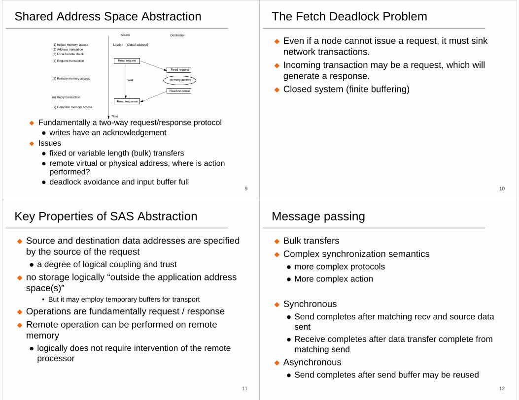
Shared Address Space Abstraction
Fundamentally a two-way request/response protocolwrites have an acknowledgement
Issuesfixed or variable length (bulk) transfersremote virtual or physical address, where is action performed?deadlock avoidance and input buffer full
Source Destination
Time
Load r ← [Global address]
Read request
Read request
Memory access
Read response
(1) Initiate memory access(2) Address translation(3) Local /remote check
(4) Request transaction
(5) Remote memory access
(6) Reply transaction
(7) Complete memory access
Wait
Read response
10
The Fetch Deadlock Problem
Even if a node cannot issue a request, it must sink network transactions.Incoming transaction may be a request, which will generate a response.Closed system (finite buffering)
11
Key Properties of SAS Abstraction
Source and destination data addresses are specified by the source of the request
a degree of logical coupling and trustno storage logically “outside the application address space(s)”
• But it may employ temporary buffers for transport
Operations are fundamentally request / responseRemote operation can be performed on remote memory
logically does not require intervention of the remote processor
12
Message passing
Bulk transfersComplex synchronization semantics
more complex protocolsMore complex action
SynchronousSend completes after matching recv and source data sentReceive completes after data transfer complete from matching send
AsynchronousSend completes after send buffer may be reused

13
Synchronous Message Passing
Constrained programming model. Deterministic! What happens when threads added?Destination contention very limited.
Source Destination
Time
Send Pdest, local VA, len
Send-rdy req
Tag check
(1) Initiate send
(2) Address translation on Psrc
(4) Send-ready request
(6) Reply transaction
Wait
Recv Psrc, local VA, len
Recv-rdy reply
Data-xfer req
(5) Remote check for posted receive (assume success)
(7) Bulk data transferSource VA ⌫ Dest VA or ID
(3) Local/remote check
14
Asynchronous Message Passing: Optimistic
More powerful programming modelWildcard receive => non-deterministicStorage required within msg layer?
Source Destination
Time
Send (Pdest, local VA, len)
(1) Initiate send(2) Address translation
(4) Send data
Recv Psrc, local VA, len
Data-xfer reqTag match
Allocate buffer
(3) Local /remote check
(5) Remote check for posted receive; on fail, allocate data buffer
15
Asynchronous MSG Passing: Conservative
Where is the buffering?Contention control? Receiver initiated protocol?Short message optimizations
Source Destination
Time
Send Pdest, local VA, len
Send-rdy req
Tag check
(1) Initiate send(2) Address translation on Pdest
(4) Send-ready request
(6) Receive-ready request
Return and compute
Recv Psrc, local VA, len
Recv-rdy req
Data-xfer reply
(3) Local /remote check
(5) Remote check for posted receive (assume fail); record send-ready
(7) Bulk data replySource VA ⌫ Dest VA or ID
16
Key Features of Msg Passing Abstraction
Source knows send data address, destination knows receive data address
after handshake they both knowArbitrary storage “outside the local address spaces”
may post many sends before any receivesnon-blocking asynchronous sends reduces the requirement to an arbitrary number of descriptors
• fine print says these are limited too
Fundamentally a 3-phase transactionincludes a request / responsecan use optimistic 1-phase in limited “Safe” cases
17
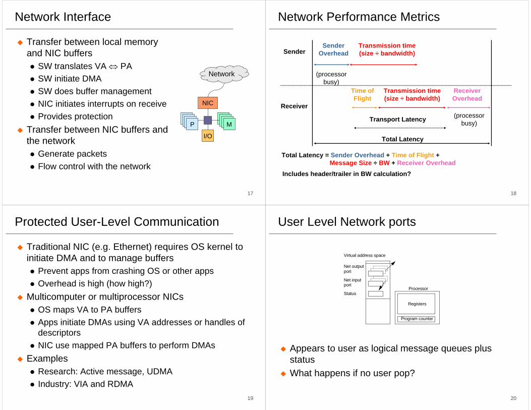
Network Interface
Transfer between local memory and NIC buffers
SW translates VA ⇔ PASW initiate DMASW does buffer managementNIC initiates interrupts on receiveProvides protection
Transfer between NIC buffers and the network
Generate packetsFlow control with the network
NIC
MMMMMMMP
I/O
Network
18
Network Performance Metrics
Sender
Receiver
SenderOverhead
Transmission time(size ÷ bandwidth)
Transmission time(size ÷ bandwidth)
Time ofFlight
ReceiverOverhead
Transport Latency
Total Latency = Sender Overhead + Time of Flight + Message Size ÷ BW + Receiver Overhead
Total Latency
(processorbusy)
(processorbusy)
Includes header/trailer in BW calculation?
19
Protected User-Level Communication
Traditional NIC (e.g. Ethernet) requires OS kernel to initiate DMA and to manage buffers
Prevent apps from crashing OS or other appsOverhead is high (how high?)
Multicomputer or multiprocessor NICsOS maps VA to PA buffersApps initiate DMAs using VA addresses or handles of descriptorsNIC use mapped PA buffers to perform DMAs
ExamplesResearch: Active message, UDMAIndustry: VIA and RDMA
20
User Level Network ports
Appears to user as logical message queues plus statusWhat happens if no user pop?
Virtual address space
Status
Net outputport
Net inputport
Program counter
Registers
Processor
21
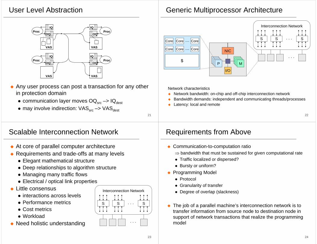
User Level Abstraction
Any user process can post a transaction for any other in protection domain
communication layer moves OQsrc –> IQdest
may involve indirection: VASsrc –> VASdest
ProcOQ
IQ
VAS
ProcOQ
IQ
VAS
ProcOQ
IQ
VAS
ProcOQ
IQ
VAS
22
Generic Multiprocessor Architecture
Network characteristicsNetwork bandwidth: on-chip and off-chip interconnection networkBandwidth demands: independent and communicating threads/processesLatency: local and remote
Interconnection Network
S S S. . .
. . .NIC
MMMMMMMP
I/O
Core
Core
Core Core…
Core Core…
$
23
Scalable Interconnection Network
At core of parallel computer architectureRequirements and trade-offs at many levels
Elegant mathematical structureDeep relationships to algorithm structureManaging many traffic flowsElectrical / optical link properties
Little consensusinteractions across levelsPerformance metrics Cost metricsWorkload
Need holistic understanding
Interconnection Network
S S S. . .
. . .
24
Requirements from Above
Communication-to-computation ratio⇒ bandwidth that must be sustained for given computational rate
Traffic localized or dispersed?Bursty or uniform?
Programming ModelProtocolGranularity of transferDegree of overlap (slackness)
The job of a parallel machine’s interconnection network is to transfer information from source node to destination node in support of network transactions that realize the programming model

25
Characteristics of A Network
Topology (what)Physical interconnection structure of the network graphDirect: node connected to every switchIndirect: nodes connected to specific subset of switches
Routing Algorithm (which)Restricts the set of paths that messages may followMany algorithms with different properties
Switching Strategy (how)How data in a message traverses a routeStore and forward vs. cut through
Flow Control Mechanism (when)When a message or portions of it traverse a routeWhat happens when traffic is encountered?
26
Basic Definitions
Network interfaceCommunication between a node and the network
LinksBundle of wires or fibers that carries signals
SwitchesConnects fixed number of input channels to fixed number of output channels
27
Network Basics
Link made of some physical mediawire, fiber, air
with a transmitter (tx) on one endconverts digital symbols to analog signals and drives them down the link
and a receiver (rx) on the othercaptures analog signals and converts them back to digital signals
tx+rx called a transceiver
0110 0110
28
Traditional Network Media
Copper, 1mm think, twisted to avoidattenna effect (telephone)"Cat 5" is 4 twisted pairs in bundle
Used by cable companies: high BW, good noise immunity
Light: 3 parts are cable, light source, light detector.Note fiber is unidirectional; need 2 for full duplex
Twisted Pair:
Coaxial Cable:
Copper coreInsulator
Braided outer conductor
Plastic Covering
Fiber OpticsTransmitter– L.E.D– Laser Diode
Receiver– Photodiode
lightsource Silica core
Total internalreflection
Cladding
Cladding
Buffer
Buffer

29
Emerging Media
Proximity project (Sun Microsystems)Potentially deliver TB/sec between chipsMicroscopic metal pads coated with a micron-thin layer of insulator to protect the chip from static electricityTwo chips contact each other
30
Networks in Parallel MachinesSome old machines
New machinesCray XT3 and XT4: 3D torus, 7GB/sec each linkIBM Bluegene/L: 3D torus, 1.4Gb/sec each link
31
Linear Arrays and Rings
Linear ArrayDiameter?Average Distance?Bisection bandwidth?Route A -> B given by relative address R = B-A
Torus?Examples: FDDI, SCI, FiberChannel Arbitrated Loop, KSR1
Linear Array
Torus
Torus arranged to use short wires
32
Multidimensional Meshes and Tori
d-dimensional arrayn = kd-1 X ...X kO nodesdescribed by d-vector of coordinates (id-1, ..., iO)
d-dimensional k-ary mesh: N = kd
k = d√Ndescribed by d-vector of radix k coordinate
d-dimensional k-ary torus (or k-ary d-cube)?
2D Grid 3D Cube

33
Properties
Routingrelative distance: R = (b d-1 - a d-1, ... , b0 - a0 )traverse ri = b i - a i hops in each dimensiondimension-order routing
Average Distance Wire Length?d x 2k/3 for meshdk/2 for cube
Degree?Bisection bandwidth? Partitioning?
k d-1 bidirectional linksPhysical layout?
2D in O(N) space Short wireshigher dimension?
34
Embeddings in Two Dimensions
Embed multiple logical dimension in one physical dimension using long wires
6 x 3 x 2
35
Hypercubes
Also called binary n-cubes. # of nodes = N = 2n.O(logN) HopsGood bisection BWComplexity
Out degree is n = logN
correct dimensions in orderwith random comm. 2 ports per processor
0-D 1-D 2-D 3-D 4-D 5-D !
36
Multistage Network
Routing from left to rightTypically n = log(p)

37
Trees
Diameter and ave distance logarithmick-ary tree, height d = logk Naddress specified d-vector of radix k coordinates describing path down from root
Fixed degreeRoute up to common ancestor and down
R = B xor Alet i be position of most significant 1 in R, route up i+1 levelsdown in direction given by low i+1 bits of B
H-tree space is O(N) with O(√N) long wiresBisection bandwidth? 38
Fat-Trees
Fatter links (really more of them) as you go up, so bisection BW scales with N
Fat Tree
39
Topology Summary
All have some “bad permutations”many popular permutations are very bad for meshes (transpose)randomness in wiring or routing makes it hard to find a bad one!
Topology Degree Diameter Ave Dist Bisection D (D ave) @ P=1024
1D Array 2 N-1 N/3 1 huge
1D Ring 2 N/2 N/4 2
2D Mesh 4 2 (N1/2 - 1) 2/3 N1/2 N1/2 63 (21)
2D Torus 4 N1/2 1/2 N1/2 2N1/2 32 (16)
k-ary n-cube 2n nk/2 nk/4 nk/4 15 (7.5) @n=3
Hypercube n =log N n n/2 N/2 10 (5)
40
How Many Dimensions?
n = 2 or n = 3Short wires, easy to buildMany hops, low bisection bandwidthRequires traffic locality
n >= 4Harder to build, more wires, longer average lengthFewer hops, better bisection bandwidthCan handle non-local traffic
k-ary d-cubes provide a consistent framework for comparisonN = kdscale dimension (d) or nodes per dimension (k)assume cut-through
41
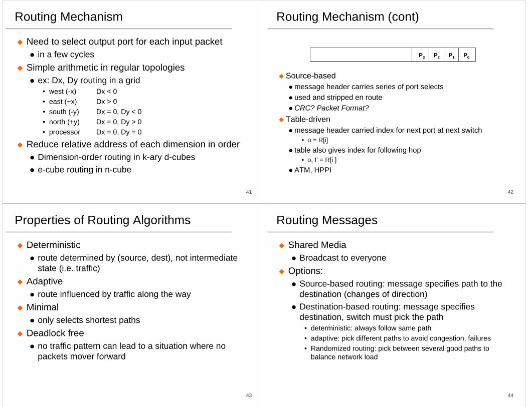
Routing Mechanism
Need to select output port for each input packetin a few cycles
Simple arithmetic in regular topologiesex: Dx, Dy routing in a grid
• west (-x) Dx < 0• east (+x) Dx > 0• south (-y) Dx = 0, Dy < 0• north (+y) Dx = 0, Dy > 0• processor Dx = 0, Dy = 0
Reduce relative address of each dimension in orderDimension-order routing in k-ary d-cubese-cube routing in n-cube
42
Routing Mechanism (cont)
Source-basedmessage header carries series of port selectsused and stripped en routeCRC? Packet Format?
Table-drivenmessage header carried index for next port at next switch
• o = R[i]table also gives index for following hop
• o, I’ = R[i ]ATM, HPPI
P0P1P2P3
43
Properties of Routing Algorithms
Deterministicroute determined by (source, dest), not intermediate state (i.e. traffic)
Adaptiveroute influenced by traffic along the way
Minimalonly selects shortest paths
Deadlock freeno traffic pattern can lead to a situation where no packets mover forward
44
Routing Messages
Shared MediaBroadcast to everyone
Options:Source-based routing: message specifies path to the destination (changes of direction)Destination-based routing: message specifies destination, switch must pick the path
• deterministic: always follow same path• adaptive: pick different paths to avoid congestion, failures• Randomized routing: pick between several good paths to
balance network load

45
Deadlock Freedom
How can it arise?necessary conditions:
• shared resource• incrementally allocated• non-preemptible
think of a channel as a shared resource that is acquired incrementally• source buffer then destination buffer• channels along a route
How do you avoid it?constrain how channel resources are allocated
How to prove that a routing algorithm is deadlock free
46
Deterministic Routing Examples
Mesh: dimension-order routing(x1, y1) -> (x2, y2)first x = x2 - x1,then y = y2 - y1,
Hypercube: edge-cube routingX = xox1x2 . . .xn -> Y = yoy1y2 . . .ynR = X xor YTraverse dimensions of differing address in order
Tree: common ancestorDeadlock free? 001
000
101
100
010 110
111011
47
Store and Forward vs. Cut-Through
Store-and-forwardeach switch waits for the full packet to arrive in switch before sending to the next switchApplications: LAN or WAN
Cut-through routingswitch examines the header, decides where to send the messagestarts forwarding it immediately
48
Store&Forward vs Cut-Through Routing
h(n/b + D) vs n/b + h Dwhat if message is fragmented?
23 1 0
23 1 0
23 1 0
23 1 0
23 1 0
23 1 0
23 1 0
23 1 0
23 1 0
23 1 0
23 1 0
23 1
023
3 1 0
2 1 0
23 1 0
0
1
2
3
23 1 0Tim e
Store & For ward R outing C ut-Through R outing
S ourc e De st Dest

49
Cut-Through vs. Wormhole Routing
In wormhole routing, when head of message is blocked, message stays strung out over the network, potentially blocking other messages (needs only buffer the piece of the packet that is sent between switches). Cut through routing lets the tail continue when head is blocked, accordioning the whole message into a single switch. (Requires a buffer large enough to hold the largest packet).
ReferencesP. Kermani and L. Kleinrock, Virtual cut-through: A new computer communication switching technique. Computer Networks, vol. 3, pp. 267-286, 1979. W.J. Dally and C.L. Seitz, “Deadlock-Free Message Routing in Multiprocessor Interconnection Networks,” IEEE Trans. Computers, Vol. C-36, No. 5, May 1987, pp. 547-553
50
Contention
Two packets trying to use the same link at same timelimited bufferingdrop?
Most parallel mach. networks block in placelink-level flow controltree saturation
Closed system - offered load depends on delivered
51
Flow Control
What do you do when push comes to shove?ethernet: collision detection and retry after delayFDDI, token ring: arbitration tokenTCP/WAN: buffer, drop, adjust rateany solution must adjust to output rate
Link-level flow control
Data
Ready
52
Smoothing the flow
How much slack do you need to maximize bandwidth?
LowMark
HighMark
Empty
Full
Stop
Go
Incoming Phits
Outgoing Phits
Flow-control Symbols

53
Virtual Channels
W.J. Dally, “Virtual-Channel Flow Control,” Proceedings of the 17th annual international symposium on Computer Architecture, p.60-68, May 28-31, 1990
Packet switchesfrom lo to hi channel
54
Bandwidth
What affects local bandwidth?packet density b x n/(n + ne)routing delay b x n / (n + ne + wD)contention
• endpoints• within the network
Aggregate bandwidthbisection bandwidth
• sum of bandwidth of smallest set of links that partition the networktotal bandwidth of all the channels: Cbsuppose N hosts issue packet every M cycles with ave dist
• each msg occupies h channels for l = n/w cycles each• C/N channels available per node• link utilization r = MC/Nhl < 1
55
Some Examples
T3D: Short, Wide, Synchronous (300 MB/s)24 bits
• 16 data, 4 control, 4 reverse direction flow controlsingle 150 MHz clock (including processor)flit = phit = 16 bitstwo control bits identify flit type (idle and framing)
• no-info, routing tag, packet, end-of-packetT3E: long, wide, asynchronous (500 MB/s)
14 bits, 375 MHzflit = 5 phits = 70 bits
• 64 bits data + 6 controlswitches operate at 75 MHzframed into 1-word and 8-word read/write request packets
Cost = f(length, width) ?
56
Switches
With virtual channels, a buffer becomes multiple buffersWho selects a virtual channel?
Cross-bar
InputBuffer
Control
OutputPorts
Input Receiver Transmiter
Ports
Routing, Scheduling
OutputBuffer

57
Switch Components
Output portstransmitter (typically drives clock and data)
Input portssynchronizer aligns data signal with local clock domainessentially FIFO buffer
Crossbarconnects each input to any outputdegree limited by area or pinout
BufferingControl logic
complexity depends on routing logic and scheduling algorithmdetermine output port for each incoming packetarbitrate among inputs directed at same output
58
Bluegene/L: A Low Power Design
BG/L 2048 processors
20.1 kW
450 Thinkpads
(LS Mok,4/2002)
20.3 kW
59
Comparing Systems
7005001000375MHz
65,5366404096512# Nodes
100400200100Cost ($M)
1.56-8.53.81Power (MW)
2,50034,00020,00010,000Footprint (sq ft)
3210338Total Mem. (TBytes)
36740.963012.3Machine Peak (TF/s)
Blue Gene/L
Earth Simulator
ASCI QASCI White
60
Supercomputer Peak Performance
1940 1950 1960 1970 1980 1990 2000 2010Year Introduced
1E+2
1E+5
1E+8
1E+11
1E+14
1E+17
Peak
Spe
ed (f
lops
)Doubling time = 1.5 yr.
ENIAC (vacuum tubes)UNIVAC
IBM 701 IBM 704IBM 7090 (transistors)
IBM StretchCDC 6600 (ICs)
CDC 7600CDC STAR-100 (vectors) CRAY-1
Cyber 205 X-MP2 (parallel vectors)
CRAY-2X-MP4 Y-MP8
i860 (MPPs)
ASCI White, ASCI Q
PetaflopBlue Gene/L
Blue Pacific
DeltaCM-5 Paragon
NWT
ASCI Red OptionASCI Red
CP-PACS
Earth
VP2600/10SX-3/44
Red Storm
ILLIAC IV
SX-2
SX-4
SX-5
S-810/20
T3D
T3E
multi-Petaflop
Thunder

61
BlueGene/L Compute ASIC
PLB (4:1)
揇ouble FPU?
Ethernet Gbit
JTAGAccess
144 bit wide DDR256/512MB
JTAG
Gbit Ethernet
440 CPU
440 CPUI/O proc
L2
L2
MultiportedSharedSRAM Buffer
Torus
DDR Control with ECC
SharedL3 directoryfor EDRAM
Includes ECC
4MB EDRAM
L3 CacheorMemory
6 out and6 in, each at 1.4 Gbit/s link
256
256
1024+144 ECC256
128
128
32k/32k L1
32k/32k L1
揇ouble FPU?
256
snoop
Tree
3 out and3 in, each at 2.8 Gbit/s link
GlobalInterrupt
4 global barriers orinterrupts
128
• IBM CU-11, 0.13 µm• 11 x 11 mm die size• 25 x 32 mm CBGA• 474 pins, 328 signal• 1.5/2.5 Volt
62
BlueGene/L Interconnection Networks3 Dimensional Torus
Interconnects all compute nodes (65,536)Virtual cut-through hardware routing1.4Gb/s on all 12 node links (2.1 GB/s per node)1 µs latency between neighbors, 5 µs to the farthest4 µs latency for one hop with MPI, 10 µs to the farthestCommunications backbone for computations0.7/1.4 TB/s bisection bandwidth, 68TB/s total bandwidth
Global TreeOne-to-all broadcast functionalityReduction operations functionality2.8 Gb/s of bandwidth per linkLatency of one way tree traversal 2.5 µs ~23TB/s total binary tree bandwidth (64k machine)Interconnects all compute and I/O nodes (1024)
Low Latency Global Barrier and InterruptLatency of round trip 1.3 µs
EthernetIncorporated into every node ASICActive in the I/O nodes (1:64)All external comm. (file I/O, control, user interaction, etc.)
BlueGene/L System Buildup
2.8/5.6 GF/s4 MB
2 processors
2 chips, 1x2x1
5.6/11.2 GF/s1.0 GB
(32 chips 4x4x2)16 compute, 0-2 IO cards
90/180 GF/s16 GB
32 Node Cards
2.8/5.6 TF/s512 GB
64 Racks, 64x32x32
180/360 TF/s32 TB
Rack
System
Node Card
Compute Card
Chip
64
512 Way Bluegene/L

65
Bluegene/L: 16384 nodes (IBM Rochester)
66
Summary
Scalable multicomputers must consider scaling issues in bandwidth, latency, power and costNetwork interface design
Substantially reduce the send and receive overheadsNetworks need to support programming models and applications wellMany network topologies have been studied, the most common ones are meshes, tori, tree and multi-stageCurrent network routers use virtual cut through, wormhole routing with virtual channelsNew-generation scalable computers must consider power scaling