scanned image - ceb
TRANSCRIPT
082:2019
CEBSPECIFICATION
MEDIUM VOLTAGE INSULATORSAND HARDWARE ACCESSORIES
CEYLON ELECTRICITY BOARDSRI LANKA
Telephone: +94 11 232 8051 Fax: +94 11 232 5387

CEB SPECIFICATION 082:2019
CONTENTSPagea 3TEa rcsikcccisrmtnvinanesemrarriansiideenaramamemmmnninede 3
a BUSACOONOINGacereee ecrrnarasrreucnsecee 4
A APPUCAGU CTANUARDS wciasacicccscenmaccansnnncencarnsasiatarsneninannasinaceiinnces 4
iy EUNOTRP EETrirereer an rareearenrereece aecoumarins 5
BA ECUOUEMMENIT SS FOR SELECTION isssccsccesssssccececassscrscascsscerecncsenansnpccarrieaacennasananzevesee 11
7.0 INFORMATION TO BE FURNISHED WITH THE OFFER vessessessecssscesccsssssssssssssssssssssessesees 13
8.0 PERFORMANCE GUARANTEES AND WARRANTY ....ssssccsscsccsssssssssscssccssssssssssssseseseesesen 13a 13
RO SRerenceenonecents .13
11.0 PACKING AND LABELING/MARKING w.scssssssecescscsssscscscsscsesssssssssssssssssssvecssssecsesesseseceeeseeees 14
12.0 INSPECTION AND TESTING. ..ccssscccscssccsccssssssssscesesceccsssssssssssecessecssssssssussesseeceresssnssnusseeeeees 14
413.0 ANNEXES ..cncccccssssssssssccesssscccssssssssssesssesesessssssssssscecessesssssssssususeseesessssssnsssesssesesssssssnnveeeseeeeee 15
2/42

CEB SPECIFICATION 082:2019
SPECIFICATION FOR MEDIUM VOLTAGE INSULATORS ANDHARDWARE ACCESSORIES
1.0 SCOPE
This specification covers the general requirements of the design, manufacturing and testing ofundermentioned Medium Voltage Hardware and Accessories.
Insulator Types:
ItemDesignation
A 11kV / 33kV Pin Insulators (without pin).11kV / 33kV Pin Post Porcelain Insulators.11kV / 33kV Pin Post Composite Insulators.11kV / 33kV Station Post Insulators.Disc Insulator Unit (Normal Profile) 7OKN/120kKN.
Disc Insulator Unit (Aerodynamic Profile) 7OKN/120KN.
33kV Composite Tension Insulators 70KN/120KN.
Item Description
Q|
nm)
mM)
oOlo|w
Insulator HardwareFittings:
ItemDesignation
Item Description
Pins for 11kV / 33kV Pin Insulators.Bolted Clamps (shackle gun) for Tension Insulator Sets for Racoon Conductor.Bolted Clamps (shackle gun) for Tension Insulator Sets for Lynx and Elm Conductor.Crimped type clamps for Tension Insulator Sets for Lynx / Elm Conductor.Crimped type clampsfor Tension Insulator Sets for Racoon Conductor.Crimped type clamps for Tension Insulator Sets for Zebra Conductor.Suspension Clamps for Racoon conductors.Suspension Clamps for Lynx and Elm conductors.Suspension Clamps for Zebra conductors.70KN/120KN Anchor Shackle, Socket eye and Ball eye with accessories.OO}
VIO]
Zl
=S=i/rj},xA;c}—|
=z
The procurement entity will prescribe items from the above categories with relevant Voltage,Failing Load and Conductor Typein price schedule as applicable.
2.0 SYSTEM PARAMETERS
(a) Nominal voltage (U) 11 kV 33 kV(b) System highest voltage (Um) 12 kV 36 kV(c) System frequency 50 Hz 50 Hz
; Effectively Non- Effectively(d) Methodof earthing earthnd earthed(e) System fault level / duration 12.5kA/1 Second 16kA/1second
3/42

3.0 SERVICE CONDITIONS
CEB SPECIFICATION 082:2019
' (a) Annual average ambient temperature|30°C| (b) Maximum ambient temperature 40°C(c)|Maximum relative humidity 90%
(d)|Environmental conditions Humid tropical climate with heavily pollutedatmosphere
(e) Operational altitude From M.S.L. to 1900 m above M.S.L.(f) Isokeraunic (Thunder days) level 100 days
4.0 APPLICABLE STANDARDS
The equipment and components supplied shall be in accordance with the latest editions of thestandards specified below and amendments thereof.
(a) IEC 60383-1:1993Insulators for overhead lines with a nominal voltage above1000 V - Part 1: Ceramic or glass insulator units for a.c.systems- Definitions, test methods and acceptance criteria
(b) IEC 60383-2:1993Insulators for overhead lines with a nominal voltage above1000 V - Part 2: Insulator strings and insulator sets for a.c.systems- Definitions, test methods and acceptance criteria
(c) IEC 61109:2008
Insulators for overhead lines - Composite suspension andtension insulators for a.c. systems with a nominal voltagegreater than 1 000 V - Definitions, test methods andacceptance criteria.
(d) IEC 61466-1:2016Composite string insulator units for overhead lines with anominal voltage greater than 1 000 V - Part 1: Standardstrength and end fittings.
(e) IEC 60120:1984Dimensions of ball and socket couplings of string insulatorunits.
(f) IEC 60305:1995Insulators for overhead lines with a nominal voltage above1000 V - Ceramic or glass insulator units for a.c. systems -
Characteristics of insulator units of the cap and pin type.
(9) IEC 60372:1984 Locking devices for ball and socket couplings of string insulatorunits - Dimensions and tests.
(h) IEC 60720:1981 Characteristicsof line post insulators.
(i) IEC 60273:1990 Characteristic of indoor and outdoor post insulators forsystemswith nominal voltages greater than 1000 V.
(j) IEC 60437:1997 Radio interference test on high-voltage insulators.
Insulators for overhead lines - Composite line post insulators(k)|IEC 61952:2008 for A.C. systems with a nominal voltage greater than 1 000 V -
Definitions, test methods and acceptance criteria.
(I) IEC TS 60815-2:2008Selection and dimensioning of high-voltage insulatorsintended for use in polluted conditions - Part 2: Ceramic andglass insulators for a.c. systems
(m) IEC TS 60815-3:2008Selection and dimensioning of high-voltage insulatorsintended for use in polluted conditions - Part 3: Polymerinsulators for a.c. systems
(n) IEC 62217 - 2012 Polymeric HV insulators for indoor and outdoor use - Generaldefinitions, test methods and acceptance criteria
(0) BS EN ISO 1461: 2009 Hot dip galvanized coatings on fabricated iron and steel,2+
4/42

CEB SPECIFICATION 082:2019
articles. Specifications and test methods.
Insulator and conductor fittings for overhead power lines.Performance and general requirements.Insulator and conductor fittings for overhead power lines.Specification for a range of insulator fittings.
(p)|BS 3288-1:2014
(q)|BS 3288-2:2009
Material conforming to other International Standards which are equalto or higher but not less stringentthan the Standards stipulated above may be offered. When such alternative Standards are used,reference to such Standards shall be quoted and English language copies of such Standards shall beprovided with the offer.
Howeverin the event of discrepancy, details given in this CEB specification supersede abovestandards.
5.0 BASIC FEATURES
5.1. General Design
The insulators will be in service in a damp tropical climate where intense lightning storms atcertain periods of the year are expected. The design shall take this into account as well as tominimize the effect of local corona formation and discharge likely to cause radio interference.Insulators shall withstand dry impulse withstand voltage (1.2/50 ys) of 75kV in case of 11kV and170kV in case of 33kV insulators. Furtherit shall also withstand Wet Power Frequency (1 min.)voltage of 28kV in case of 11kV and 7OkV in case of 33kV insulators.
Porcelain insulators shall be made of good commercial grade wet-process Porcelain (brownglazed). The surface shall be smooth, uniform, and the glazed area shall be free surfaceirregularities such as sharp edges, cavities, dents and unglazed spotsetc.The design of all insulators shall be such asto facilitate inspections, cleaning, repairs, and hotline maintenance.All corresponding parts to be made to gauge andbe interchangeable.
All iron and steel parts shall be galvanized after subjecting to the processes such as sawing,shearing, drilling, punching, filing, bending and machining. Galvanizing shall be applied by hotdip process to comply with the BSEN ISO 1461 (2009) specified. The galvanized hardwarefittingsshall have a smooth and uniform thickness of zinc coating without any sharp edges.
The thickness of zinc coating shall not be less than 85ym in plain surface. All hardware itemsshall be treated with sodium dichromate after galvanizing and stored under well ventilatedconditions to prevent the formation of white rust.
5.2. Pin Insulators (Item A)
‘1; Technical Requirements1.1.|Rated Voltage (Max.|11kV (12kV) 33kV (36kV)
Voltage)1.2|Material Porcelain1.3|Insulator Class Class B as per IEC 60383-11.4|Radio Interference Semi-conducting layer to reduce radio frequency interf ce. As per
IEC - 60437 - 1997 (30dB). coNN5/42
Xo, oeNest Coord

CEB SPECIFICATION 082:2019
1.5|Applicable Conductor|28.7Size (mm), max.1.6|Size of channel iron|100x50 x 6
cross arm for fixinginsulators (mm)
1.7|Minimum Failing Load|10(kN)1.8|Minimum Creepage 275 825
Distance (mm)1.9|Creepage Factor <4 (For both Overall and Local)2 Manufacture2.1|Insulators The design parametersof the Insulators shall be in accordance with the
Drawing No. CEB/DS&S/2019/082/01.
The porcelain shall not engage directly with the hard metal and the pininsulator shall be provided with the thimble of Lead/Zinc material toaccommodate the steel pin.
2.2|Insulator head Shall be as indicated as in the Drawing No. CEB/DS&S/2019/082/02.2.3|Threaded thimbles Threaded thimbles shall be cemented to the insulators to receive the
insulator pins with large steel heads and the internal thread of thimbleshall comply with the dimensions of the large steel pin insulator head(reference no 16 of BS 3288-2). The upper part above thimble shouldhave a cushioning material.
5.3. Pin Post Insulators (Item B & C)
As Technical Requirements1.1.|Material Porcelain — Item B Silicon Rubber — Item C1.2|Rated Voltage (Max.|11kV(12kV)|33kV(36kV) 11kV(12kV)|33kV(36kV)
Voltage)1.3|Insulator Class Class A as per IEC 60383-11.4|Radio Interference Semi-conducting layer to reduce radio frequency interference. As per
IEC - 60437 - 1997 (30dB).1.5|Applicable Conductor|28.7Size (mm), max.1.6|Size of channel iron|100x50 x6cross arm for fixing
insulators (mm)1.7.|Minimum Failing Load|10(KN)1.8|Minimum Creepage 310 950 340 1000
Distance (mm)1.9|Creepage Factor <4 (For both Overall and Local)2. Manufacture2.1|Insulators The top/side shall have a grove|Manufacture shall be in accordance
with a minimum radius of 16mm|with clause 5.6 (2).to attach AAC, AAAC and ACSRconductors. The flange cover|The top/side shall have a grove withshall be made of UV resistant,|a minimum radius of 16mm toflame-retardant and anti-tracking|attach AAC, AAAC and ACSRtype semi conductive|conductors as per drawing no.polymer/rubber material as per|CEB/DS&S/2019/082/04..—drawing no. LION
~ “9
6/42

CEB SPECIFICATION 082:2019
CEB/DS&S/2019/082/03. |2.2 Insulator Steel Pin The medium voltage pin post insulator shall be supplied complete with
necessary hardware such as steel pin, nuts, spring washers and twonumbersof flat washers of suitable size for attachment to the channeliron cross-arms as specified above. The shank length of the pin shall benot less than 140mm and not more than 185mm. Diameterof the pinshall be between 20mm — 22mm.
5.4. Station Post Insulators (Item D)
1. Technical Requirements1.1.|Rated Voltage (Max. Voltage) 11kV(12kV) | 33kV(36kV)1.2|Material Porcelain1.3|Insulator Class Class A as per IEC 60383-11.4|Size of channel iron 100x50 x 6
for fixing insulators (mm)1.5|Minimum Failing Load (kN) 101.6|Total Creepage Distance (mm)|300 | 9001.7|Creepage Factor <4 (For both Overall and Local)2. Manufacture2.1|Insulators The Solid Core, Post Insulators as per IEC 60383, shall be
made of brown glazed porcelain suitable for the assemblies ofMV equipment and busbars.
2.2|Steel Hardware The Insulators and fittings shall be in accordance with theDrawing No. CEB/DS&S/2019/082/05.Both ends of the Insulator shall be fitted with malleable castlron Caps with 4 Tapped Holes, one end to receive the MV
equipment or bus bar and the other end for fixing on BaseFrame.
The Insulators supplied shall be complete with 4 bolts to fix thefixtures to the Insulator Top Cap and 4 Bolts and 4 SpringWashersto fix the Post Insulator to the Base Frame.
5.5. Disc Insulator Units (Item E & F)
Profile Type | Normal Profile Aerodynamic Profile1: Technical Requirements1.1.|Rated Voltage (Max. Voltage) 11kKV(12kV)1.2|Material Porcelain/ Toughened Glass1.3|Insulator Class Class B as per IEC 60383-11.4|Porcelain Diameter (mm) 255 280 (minimum)1.5|Insulator Spacing (mm) 146 1461.6|Standard Coupling 16 20 16 201.7.|Type/Designation as per IEC U70BL U120B U70BLP U120BP
60305.1.8|Minimum Failing Load of a disc|70 120 70 120
(KN)1.9|Total Creepage Distance per 295 350
disc (mm)1.10|Creepage Factor <4 (For both Overall and Local)2. Manufacture2.1|Insulators | The insulator shall be of the cylindrical head type’With,profite.
AS ~,aAy7/42 Oo
en asNS Dist,Coo
CEB SPECIFICATION 082:2019
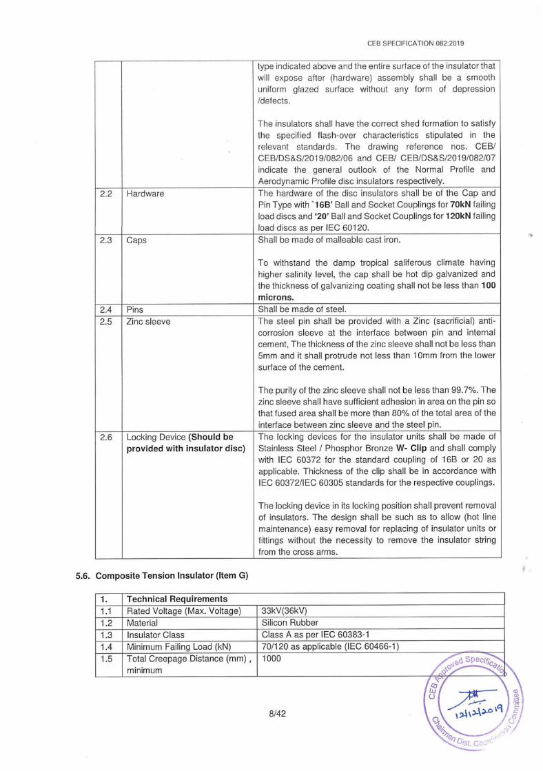
type indicated above and the entire surface of the insulator thatwill expose after (hardware) assembly shall be a smoothuniform glazed surface without any form of depression/defects.
The insulators shall have the correct shed formation to satisfythe specified flash-over characteristics stipulated in therelevant standards. The drawing reference nos. CEB/CEB/DS&S/2019/082/06 and CEB/ CEB/DS&S/2019/082/07indicate the general outlook of the Normal Profile andAerodynamic Profile disc insulators respectively.
2.2 Hardware The hardware of the disc insulators shall be of the Cap andPin Type with °16B' Ball and Socket Couplings for 70KN failingload discs and ‘20’ Ball and Socket Couplings for 120KN failingload discs as per IEC 60120.
2.3 Caps Shall be made of malleable castiron.
To withstand the damp tropical saliferous climate havinghigher salinity level, the cap shall be hot dip galvanized andthe thickness of galvanizing coating shall not be less than 100microns.
2.4 Pins Shall be madeofsteel.2.5 Zinc sleeve The steel pin shall be provided with a Zinc (sacrificial) anti-
corrosion sleeve at the interface between pin and internalcement, The thicknessof the zinc sleeve shall not be less than5mm andit shall protrude not less than 10mm from the lowersurface of the cement.
The purity of the zinc sleeve shall not be less than 99.7%. Thezinc sleeve shall have sufficient adhesion in area on the pin sothat fused area shall be more than 80% of the total area of theinterface between zinc sleeve and the steelpin.
2.6 Locking Device (Should beprovided with insulator disc)
The locking devices for the insulator units shall be madeofStainless Steel / Phosphor Bronze W- Clip and shall complywith IEC 60372 for the standard coupling of 16B or 20 asapplicable. Thickness of the clip shall be in accordance withIEC 60372/IEC 60305 standards for the respective couplings.
The locking devicein its locking position shall prevent removalof insulators. The design shall be such as to allow (hot linemaintenance) easy removal for replacing of insulator units orfittings without the necessity to remove the insulator stringfrom the cross arms.
5.6. Composite Tension Insulator (Item G)
‘ls Technical Requirements1.1.|Rated Voltage (Max. Voltage) 33kV(36kV)1.2|Material Silicon Rubber1.3|Insulator Class Class A as per IEC 60383-11.4.|Minimum Failing Load (kN) 70/120 as applicable (IEC 60466-1)1.5|Total Creepage Distance (mm) ,|1000minimum
-°mmittee
~8/42m9y~&

CEB SPECIFICATION 082:2019
ManufactureCore The insulator core shall be made of brittle fracture-resistant
electrical grade epoxy / vinyl ester / lso-polyester basedfiberglass rod to achieve maximum failing load. The core shallbe mechanically and electrically sound, free from voids,foreign substances and.manufacturing flaws.
Also the design shall be such as to ensure that the core is
totally encapsulated and fully sealed, from the live to theearthed ends,by the insulating material from the environment,in order to avoid ingress of moisture. If any tacky substancesare used as sealers, they shall not be exposed toenvironmental influence.
2.2 Housing & Weather-sheds The housing and Weather-sheds shall be madeof siliconerubber material in order to maintain their hydrophobicity duringlong term service in critical environments.
A minimum thick sheath of 3.0 mm of Silicone Rubber shall beextruded or injection moulded on the reinforced fiberglass rod.The polymer sleeve and weather-shed insulating material shallhave a chemical structure of 100 percent silicone rubberbefore fillers are added.
The silicone rubber shall be firmly bonded to the rod, beseamless, smooth and free from imperfections. The strengthof the silicone rubberto rod interface shall be greater than thetearing strength of the silicone rubber.
The weather-sheds shall be firmly bonded to the sheath,vulcanized to the sheath or molded aspart of the sheath andbe seamless smooth and free from imperfections. Thestrength of the silicone rubber weather-shed to sheathinterface shall be greater than the tearing strength of thesilicone rubber.
Weather-sheds shall be at intervals to provide optimumelectrical performance and the weather-shed designs shouldprovide a protected bottom surface that tends to keep dry in
wetconditions.2.3 Hardware base and housing The gap between hardware base and housing shall be sealed
by an elastomer with permanent elasticity. The sealing shallstick permanently to the surface of the material as well as tothe housing.
The base should be attached to insure a uniform distributionof the mechanical load to the rod. The schematic of thecomposite insulator is indicated in drawing no.CEB/DS&S/2019/082/08. Required numberof cotter pins andsplit pins shall be provided as per the given drawing.
2.4 Washing The insulator shall be capable of withstanding high-pressurepower washing.
9/42

5.7.
5.8.
CEB SPECIFICATION 082:2019
Pins for 11kV / 33kV Pin Insulators (Item H)
Insulator Pins shall be supplied complete with hot dip galvanized steel pin, nut, spring washerand two numbers of circular flat washers of suitable size in accordance with Drawing No.CEB/DS&S/2019/082/09 and as per BS 3288-2 standard.
The Insulator Pins shall be suitablefor fixing the insulators on 100x50x6mm Channel Iron Cross-arms. The shank length of the Pin shall be between 140mm — 185mm.The screwedlength shallbe 5 mm less than the shank length of the pin with isometric coarse thread.
Bolted Clamps (shackle gun) for Tension Insulator Sets for Racoon/Elm/Lynx Conductor(Item I, J)
The bolted type conductor tension clamp (Dead End Clamp) shall be made of aluminium alloywith minimum three U bolts as stipulated in drawing no. CEB/DS&S/2019/082/10 andit shall besuitable to be used with the conductoras stipulated in the scheduleof prices.
5.9. Crimped type clamps for Tension Insulator Sets for Racoon/Elm/Lynx/Zebra Conductor(Item K, L and M)
The compression type conductor tension clamp (Dead End Clamp) with jumper terminalshall bemade of aluminium alloy/steel and the jumper lug madeof aluminium alloy shall be fixed to thejumper terminal with twobolts.
The compression type tension clamp for Elm conductor shall be of single part fitting made of
aluminium alloy and for Lynx/Raccoon conductor it shall be of two-part fitting made of steeland aluminium alloy with jumper socket as shownin the drawing no. CEB/DS&S/2019/082/11and as requested in the Schedule of Prices.
5.10.Suspension Clamps for Racoon/Elm/Lynx/Zebra conductor (Item N,O and P)
Conductor Suspension Clamp shall be madeof aluminium alloy with 2 U bolts as per drawing no.CEB/DS&S/2019/082/12. for attaching conductors asstipulated in the Schedule of Prices.
5.11. 70KN/120kN Anchor Shackle, Socket eye and Ball eye with accessories (Item Q)
This shall be complete with accessories in accordance with BS 3288-2 mentioned below. Therequired failing load shall be indicated in the Schedule of Prices.
Reference No as per Reference No as perBS 3288-2 for BS 3288-2 for :Item ne ‘i 5 si Drawing Nos.minimum failing load minimum failing load70KN 120kKN
Anchor Shackle witha.|cotter pin and split 15/29 A or 15/33 A 28/29 A CEB/DS&S/2019/082/13
pin
a|oe Eee ee 15/30 28/30 CEB/DS&S/2019/082/14accessoriesSocket Eye (W-Clip
b.|inserted) with cotter|15/35 28/36A CEB/DS&S/2019/082/15pin andsplit pin
10/42

CEB SPECIFICATION 082:2019
6.0 REQUIREMENTS FOR SELECTION
6.1. Quality Assurance
The manufacturer shall possess ISO 9001:2015 or latest Quality Assurance Certification validthroughout the delivery period of this bid, for the manufacture of offered Insulator/HardwareCategory where manufacturing is intended. The Bidder shall furnish a copy of the ISO certificatecertified as true copyof the original by the manufacturer, along with the offer.
6.2. Manufacturing Experience
The manufacturer shall have minimum of ten (10) years experience in manufacturing Insulatorsand/or hardware fittings as applicable. Out of this period offered item should have been suppliedsuccessfully outside the country of the manufacturer for minimum of five (5) years for usage inutilities. The product offered has to be in same voltage range of offered item and shall have beenused in service utilities over past 5 years.
If the manufacturer has supplied similar items to CEB for the last five (5) years with proven salesrecords; without any adverse performance records, such manufacturers will be exempted fromabove requirements.
6.3. Type Tests
The following Type Test Certificates conforming to above referred standards in Clause 4.0 or anyother international standard which is not less stringent, issued by:
Either
(a) an accredited independent testing laboratory acceptable to the CEB or
(b) an accredited or independent testing laboratory acceptable to the CEB where the typetestshave been witnessed by CEBor a reputed independent body acceptable to CEB
shall be furnished with the offer. Type Test Certificates shall clearly indicate the relevant standard,items concerned, showing the manufacturers identity, type No. /catalogue No. and basic technicalparameters. In caseif the submitted type tests are according to any other international standardwhichis not less stringent than the specified, then the copy of the used standard in English shallbe submitted with offer.
Proof of accreditation and accredited scope by a national/ international authority shall beforwarded with the offer. Test certificates shall be complete including all the pages as issued bythe testing authority. Type test certificates shall be in English language. Parts of test certificatesshall not be acceptable.
11/42

CEB SPECIFICATION 082:2019
Type Tests for Insulators in accordance with IEC 60383-1, IEC 60383-2, IEC 61109 and IEC61952 as applicable:
Item DesignationTest Description A B Cc D E* FE G
Verification of the dimensions Vv V V v V Vv Vv
Dry lightning impulse withstand voltage test Vv Vv v Vv Vv v v
Wet- power frequencywithstand voltage test Vv Vv Vv v V v Vv
Mechanical failing load test Vv Vv Vv Vv Vv Vv Vv
Electro-mechanicalfailing load test - - - - v Vv -
Thermal mechanical performance test as per | - - - - Vv Vv -
IEC60575Artificial pollution tests as per IEC60507 - - - - - V -
Residual strength test as per IEC 60797 - - - - - V -
Cement Auto Clave Expansion test as per ANSI | - - - - - V -
C29-2:1992 & ASTM C151.84Power arc test as per IEC 61467 “ - - - - Vv -
Qualification tests for W-Clips as per IEC 60372| - - - - v Vv -
(Hardness Test and Corrosion Resistance Test)
*The Test Certificates shall be given for string insulator unit (disc) as well as for completeSuspension and Tension Insulator sets as applicable.
TypeTests for Insulator fittings in accordance with BS 3288-1 as applicable:
Item DesignationTest Description H 1&J |KL&|NO&|}Q
M PMechanical tests Vv Vv Vv v vResistance tests - V Vv - -
Electrical heating cycle test - V V - -
Qualification tests for W-Clips as per IEC 60372|- - - - V
(Hardness Test and Corrosion Resistance Test)
6.4. Design Tests
Following design tests as per the relevant standards prescribed in clause 4.0 shall be furnishedwith the offer in case of composite insulators (for item C and G) as applicable:
e Tests on interfaces and connectionsof end fittings(a) Pre-stressing — Sudden load release pre-stressing(b) Thermal-mechanical pre-stressing(c) Water immersion pre-stressing(d) Verification tests(e) Visual examination(f) Steep-front impulse voltage test(g) Dry power-frequency voltage test
e Tests on shed and housing material(a) Hardness test
12/42

CEB SPECIFICATION 082:2019
(b) Accelerated weathering test(c) Tracking and erosion test(d) Flammability test
e Tests on the core material(a) Dye penetration test(b) Water diffusion test
e Assembled core load-time test(a) Determination of the average failing load of the core of the assembled insulator(b) Control of the slope of the strength-time curve of the insulator
7.0 INFORMATION TO BE FURNISHED WITH THE OFFER
The following shall be furnished with the offer.
(a) Following technical details in English clearly identifying the offered items, but not limited to:
(i) Comprehensive catalogues.(ii) Dimensional drawings.(iii) Schematic diagrams.(iv) Calculations, graphs and tables.(v) Operational literature.
(b) ISO 9001:2015 or latest Quality Assurance Certificate in accordance with clause 6.1.
(c) Manufacturer shall furnishalist of supplies with supplied item, purchaser (specifying addresscontact persons and contact details, country), year & quantity to prove his manufacturingexperience and outside the country sales in accordance with Clause 6.2.
(d) Type Test Certificates and Design Test Certificates in accordance with the clause 6.3 and6.4.
(e) Duly filled and signed ‘Annex - B: Schedule of Technical Requirements and GuaranteedTechnical Particulars’.
Not furnishing above documents and details may result in offer being rejected.
8.0 PERFORMANCE GUARANTEES AND WARRANTY
Manufacturer should provide CEB a warranty ensuring that items supplied meet the specificationand any defected items shall be replaced without extra cost during the first year after the finaldelivery to CEBstores.
9.0 SAMPLES
One sample of the make and modelof the item quoted shall be supplied with the offer by the Bidderto facilitate analysis and evaluation of tender.
10.0 SPARES
NotApplicable.
13/42

CEB SPECIFICATION 082:2019
11.0 PACKING AND LABELING/MARKING
4151.
THs
Packing
Insulators and Hardware Fittings shall be packed in non-returnable palletized boxes suitablefor overseas shipmentto a tropical country.
In packing cases where timber is used for reinforcement, the thickness of such timber partsshall not be less than 25mm and the packing shall also be suitable to withstand roughhandling without sustaining damages.
The following details shall be marked clearly on the outside of all packages:-a) Nameof Item and Voltage ratingb) Quantityc) Weight
Identification and Labeling/Marking
The Identification details shall be permanently marked as below on the insulators andhardware fittings and they shall be weatherproof.In caseof Insulators:
a) Manufacturer's Identificationb) Minimum failing load in KN.
c) Year of manufacture.d) Coupling type designation if applicable.
In case of Hardwarefittings:a) Manufacturer's Identificationb) Minimum failing load in KN and coupling type designation if applicable.
12.0INSPECTION AND TESTING
12.1.
12.2.
Routine Tests
Depending on the choice of the applicable standards, the following relevant Routine TestCertificates conforming to, but not limited to, the IEC 60383/ IEC 61109/BS 3288 standardsshall be furnished for the observation of the Engineer appointed by the purchaser at the timeof inspection. In addition, the routine test certificates shall be sent with the shipmentof theitems.
(a) Mechanical routine tests(b) Electrical routine tests(c) Visual examinations
Inspection
The Successful bidder shall make necessary arrangements for inspection by an Engineerappointed by the CEB and also to carry out in his presence necessary Acceptance tests onprocured item and material without any additional cost. Acceptance test reports shall be apart of the shipping document. CEB may waiveoff the inspection either with the conditionof witnessing the acceptance tests by an independent body acceptable to CEB or
14/42

CEB SPECIFICATION 082:2019
12.3. Acceptance Tests
Depending on the choice of the applicable standards, the following Sample/Acceptance Testsconforming below mentioned standards shall be witnessed by the Engineer appointed byCEB.
AcceptanceTests for Insulators in accordance with IEC 60383-1, IEC 60383-2, IEC61109, IEC 61952 and IEC 60372as applicable:
Item DesignationTest DescriptionVerification of dimensionsTemperature cycle testMechanical failing load testPuncture withstand testPorosity TestGalvanizing test vVerification of the locking system -
Verification of the tightness of the interface between|- - - -
end fittings and insulator housingVerification of the specified mechanical load/|- - V . - -
cantilever loadVerification of displacement - - - "
Electro-mechanical failing load test - - . =
Sample tests for W-Clips as per IEC 60372 - - - -
elelelorye]
2zlelelo
2j2j2}elei>
2j2)' ' Celi
3
aesqusssesm sasqqsasasasst
'
<~/-/4)'
a
aja]
Jayes '
Acceptance Tests for Insulator fittings in accordance with BS 3288-1, IEC 60372 asapplicable:
Item DesignationTest Description H 1&J r Re N,O &
Verification of the dimensionsMechanical Tests/Electrical TestsGalvanizing TestsClamp Bolt Tightening TestsSample tests for W-Clips as per IEC 60372 - -
2zJ2l/ei/u
2zJ2z/2]}
09
2]
2]
2! 2zjJ2eJel2xyyV
V
' ' a
13.0 ANNEXES
Al :Design Parameters for Porcelain Pin Type Insulator for MV Lines
A2—:Head of MV Porcelain Insulators
A3 :Porcelain Pin Post Insulator 11 kV / 33 kV
A4=:Composite Pin Post Insulator 11kV / 33 kV
A5 __:Station Type Porcelain Post Insulator 11 kV & 33 kV Reference IEC Publication: 60273
A6 :Porcelain Disc Insulators NormalProfileA7 :Porcelain Disc Insulators Aerodynamic TypeA8&=:Schematic Diagram of Silicon Rubber Composite Insulator
15/42

AQ
A10
Al1
A12
A13
A14
A15
B1
B2
B3
B4
BS
Cc
CEB SPECIFICATION 082:2019
711. kV & 33 kV Insulator Pin
:Schematic Diagram of Bolted Tension Clamps (70kN)
:Schematic Diagram of Compression Clamp (120KN)
:Schematic Diagram of Suspension Clamp ( 70 kN)
:Schematic Diagram of Anchor Shackle For Composite and Porcelain Type Insulators(Reference Standard. BS 3288-2)
:Schematic Diagram of Ball Eye (Reference Standard: BS 3288-2)
:Schematic Diagram of Socket Eye (Reference Standard BS 3288-2)
‘Schedule of Technical Requirements and Guaranteed Technical Particulars - Properties ofMaterial used for Insulators
:Schedule of Technical Requirements and Guaranteed Technical Particulars - For Pin, Pin Postand Station Post Insulators‘Schedule of Technical Requirements and Guaranteed Technical Particulars - For DiscInsulators
:Schedule of Technical Requirements and Guaranteed Technical Particulars - For CompositeTension Insulators
:Schedule of Technical Requirements and Guaranteed Technical Particulars - For InsulatorHardware Fittings:Non — Compliance Schedule
16/42

Porcelain Shell
CEB STANDARD 082 - 2019Annexure A -1
Cement Cork / Rubber Seperator5mm < Thickness <15mm
di Thimble (Zinc / Lead)
Semi-Conductor Glazewy ML, to minimise Radio Interference
AGU &vy, ES Al
<Zee
EY, =°%“] &Q¢
ds
CreepageOverall Creepage Factor = <4
(di +d2+d3+d4+d5)C
Local Creepage Factor = —— <4a
Shed spacing h= — > 08
Shed overhang t
DISTRIBUTION STANDARDS & SPECIFICATIONS SCALE : NOT TO SCALE
CEYLON DESIGN PARAMETERS FOR DRAWN :LALANI |EDITED : HARSHA
Gpgetecreiciry PORCELAIN PIN TYPE INSULATOR FOR MV LINESBOARD DATE : NOV- 2019
DESIGNED BY APPROVED BY
DRG. NO: DS&S/2019/082/01a EE (DC) CHAIRMAN, SPECIFICATION COMMITTEE CAD NO :
17/42

142
12024
CEB eae 082: 2019
NOTE:
Tolerances shall be [0.04d + 1.5 ] mm, where‘d' is the dimensions shown in the drawing.
ALL DIMENSIONS ARE IN MILLIMETRES.
>nnexure A-2
CEYLONEi datecracmyBOARD
DISTRIBUTION STANDARDS & SPECIFICATIONS SCALE : NOT TO SCALE
HEAD OF MV PORCELAIN INSULATORSDRAWN : LALANI EDITED : HARSHA
DISTRIBUTION COORDINATIONBRANCH
DESIGNED BY
EE (0C)
APPROVED BY
CHAIRMAN, SPECIFICATION COMMITTEE
DATE : NOV- 2019
DRG. NO: DS&S/2019/082/02
CAD NO :
18/42

CEB STANDARD 082:2019Annexure A-3
140-185
| 20ALL DIMMENSIONS AREIN MILLIMETERS
CEYLONEfpetectaicryBOARD
DISTRIBUTION STANDARDS & SPECIFICATIONS SCALE : NOT TO SCALE
PORCELAIN PIN POST INSULATOR DRAWN : LALANI|EDITED : HARSHA/
DISTRIBUTION COORDINATIONBRANCH
11 kV/33 kVDESIGNED BY APPROVED BY
EE (0c)|CHAIRMAN, SPECIFICATION COMMITTEE
DATE : NOV- 2019
DRG. NO: DS&S/2019/082/03
CAD NO :
19/42

CEB STANDARD 082 : 2019Annexure A-4
ayR16 R16
|
|
1
1
!SsUi ¢ems|'
|
| 20-22
ALL DIMMENSIONS AREIN MILLIMETERS
DISTRIBUTION STANDARDS & SPECIFICATIONS SCALE : NOT TO SCALE
DRAWN : LALANI EDITED : HARSHACEYLON COMPOSITE PIN POST INSULATORG@getectricrry 11kV / 33kV
BOARDDESIGNED BY APPROVED BY
DISTRIBUTION COORDINATIONBRANCH EE (0C) CHAIRMAN, SPECIFICATION COMMITTEE
DATE : NOV- 2019
DRG. NO : DS&S/2019/082/04
CAD NO:
20/42

|115mm
CEB STANDARD 082: 2019Annexure A-5
RATED IEC-60273 (D) mm (h) mmVOLTAGE (Max)} IDENTIFICATION
11kV (12kV) C10-75 190 21541
33kV (36kV) C10-170 245 44541
CREEPAGE DISTANCE CLASS 2
1. Total Creepage distance not less than 25mm/kV of normal voltage.
2. Protected Creepage distance not less than 35% of the above.
Not to excbed 'D'mm
“coetifican”ooecilicas.feos Yon
©2
. €ae
4 Nos.of Holes tapped M12 on 76 PCD
ee
ee
a
at
o q f o q —
a
>
115;mm| |
All dimensions are in mm.
DISTRIBUTION STANDARDS & SPECIFICATIONS SCALE : NOT TO SCALE
CEYLON STATION TYPE PORCELAIN POST INSULTOR DRAWN : LALANI JEDITED : HARSHA
ELECTRICITY 11 KV & 33 kV
BOARD REFERENCE IEC PUBLICATION: 60273(1990 DATE : NOV-2019DESIGNED BY APPROVED BY
DRG. NO: DS&S/2019/082/05SS EE(0C)|CHAIRMAN, SPECIFICATION COMMITTEE|CAD NO :
21/42

CEB STANDARD 082: 2019Annexure A-6
146
cb255
FRONT ELEVATION
146
| 255
SIDE ELEVATIONALL DIMMENSIONS AREIN MILLIMETERS
DISTRIBUTION STANDARDS & SPECIFICATIONS SCALE : NOT TO SCALE
CEYLON PORCELAIN DISC INSULATORS DRAWN : LALANI|EDITED : HARSHA
ELECTRICITYGRgececrNORMAL PROFILE ware ENE BnAE
DESIGNED BY APPROVED BY
DRG. NO: DS&S/2019/082/06
agaaca EE (DC) CHAIRMAN, SPECIFICATION COMMITTEE CAD NO :
22/42

CEB STANDARD 082. 2019Annexure A-7
146
5280 (Min)
FRONT ELEVATION
146
<5280 (Min)
SIDE ELEVATIONALL DIMMENSIONS AREIN MILLIMETERS
DISTRIBUTION STANDARDS & SPECIFICATIONS SCALE : NOT TO SCALE
DRAWN : LALANI|DRAWN : HARSHA
DATE : NOV- 2019
CEYLON PORCELAIN DISC INSULATORSER patectacmy AERODYNAMIC TYPE
BOARDDESIGNED BY APPROVED BYea EE (OC) CHAIRMAN, SPECIFICATION COMMITTEE
DRG. NO: DS&S/2019/082/07
CAD NO :
23/42

CEB SPECIFICATION 082 : 2019Annexure A-8
--—(F=Cotter Pin & Split Pin
o=——
|
Bog
lh
len
paiement
my
pan
ach
C )
a Ssa —: =
1 1
' '—eS) |
'|<a
|
|
|
1
~
C =Ommittee
Cotter Pin & Split Pin
—(
=
&
FRONT ELEVATION SIDE ELEVATIONNote:-* Cotter Pin Diameter for 70KN failing load shall be 16mmand for 120KNit shall be 19mm
* A/B hole sizes should match with hardware inAnnexure A10, Annexure A-11, Annexure A12 for
ALL DIMMENSIONS AREIN MILIMETERS respective failing loads
DISTRIBUTION STANDARDS & SPECIFICATIONS SCALE : NOT TO SCALE
CEYLON SCHEMATIC DIAGRAM OF DRAWN : LALANI|EDITED : HARSHA
Ep detecrricrry SILICON RUBBER COMPOSITE INSULATORBOARD DATE : NOV-2019
DESIGNED BY APPROVED BY
DRG. NO: DS&S/2019/082/08
Ceued ee EE (OC) CHAIRMAN, SPECIFICATION COMMITTEE CAD NO :
24/42

CEB REETATION4 : 2019nexure A-9
Large Steel Head ( Ref. No. 16 as per BS 3288-2)
—__—_——-
<x INSULATOR PINDESCRIPTION
11 kV 33 kV
Pin Ref. No. 29 31
A 230 mm 305 mm
B ( Min. ) 50 mm 63 mm
Cc 25 mm 27 mm
\ D ( Min.) 37 mm 40 mm
)
—tF E 22 mm 22 mm
B|
}| F 6mm 6mm
G 13mm 16mm“E Xx 140 mm 140 mm
Isometric Coarse Thread
INSULATOR PIN
Minimum Falling Load 10 kN
SCALE : NOT TO SCALE
DRAWN : LALANI EDITED : HARSHA|
DISTRIBUTION STANDARDS & SPECIFICATIONS
CEYLONGi etecrriciry 11kV & 33kV INSULATORPINBOARD
DESIGNED BY APPROVED BY
DISTRIBUTION COORDINATIONBRANCH EE (DC) CHAIRMAN, SPECIFICATION COMMITTEE
DATE : NOV-2019
DRG. NO: DS&S/2019/082/ 09
CAD NO :
25/42

Conductor
Plan View
Tension Clamp
Aluminium Lining
Note:-Applicable for Item No. (I) & (J) of Clause 1.0This should match with Socket Eye Ref. No 15/35
In case of 1.0 (I), Conductor Groove should matchwith Racoon Conductors if requested in PriceSchedule
In case of 1.0 (J), Conductor Groove should matchwith LYNX / ELM Conductors if requested in PriceSchedule
CEB SPECIFICATION 082 : 2019Annexure A-10
View at-A
CEYLON
Gf datectricrryBOARD
DISTRIBUTION STANDARDS & SPECIFICATIONS SCALE : NOT TO SCALE
SCHEMATIC DIAGRAM OF BOLTED TENSION CLAMPS (70kN)DRAWN : LALANI|EDITED : HARSHA
DISTRIBUTION COORDINATIONBRANCH
DESIGNED BY
EE (DC)
APPROVED BY
CHAIRMAN, SPECIFICATION COMMITTEE
DATE : NOV- 2019
DRG. NO: DS&S/2019/082/10
CAD NO :
26/42

CEB SPECIFICATION 082 : 2019Annexure A-11
;
|
1: I|
\\| | | |
ts | 44 eta}1] | |
| | | ||
|iy }or |
| | | |nes tte| rh | | se |
iit! ry |!|
| ||
| iti!' {yl
||
| Aluminium Alloy | ||
| | |
ity | Hit!1 | i i; | i!| ri | | lal |
iii! ria!Steel
| put | Li
Steel Bolt & Nut
FRONT ELEVATION SIDE ELEVATION
| - Note:- ~—
Applicable for Item No. (K), (L) and (M) of Clause 1.0
* This should match with Socket Eye Ref. No. 28/36 A
* If different coupling is offered all required accessories shall bePLAN VIEW provided to attach to the Socket Eye
* The Compression Sleeve should match with Racoon / LYNX /ELM/ Zebra conductors as requested in Price Schedule
DISTRIBUTION STANDARDS & SPECIFICATIONS SCALE : NOT TO SCALE
CEYLON SCHEMATIC DIAGRAM OF COMPRESSION CLAMP DRAWN : LALANI|EDITED : HARSHA
ELECTRICITY (120kN)BOARD DATE : NOV-2019
DESIGNED BY APPROVED BY
DRG. NO: DS&S/2019/082/11ea EE (DC) CHAIRMAN, SPECIFICATION COMMITTEE CAD NO :
27/42

U - Bolt| (Detailed)
Conductor
FRONT ELEVATION
SuspensionClamp
Conductor
ELEVATION AT - P
Note:-This should match with the Socket EyeRef. No. 15/35 of BS 3288-2
CEB SPECIFICATION 082 : 2019Annexure A-12
U - BOLT
DISTRIBUTION STANDARDS & SPECIFICATIONS SCALE : NOT TO SCALE
DRAWN : LALANI|EDITED : HARSHA
DATE : NOV- 2019
CEYLON SCHEMATIC DIAGRAM OF SUSPENSION CLAMPEf}etectacrry (70 KN)BOARD
DESIGNED BY APPROVED BY
IBUTION COORDINATION— BRANCH EE (OC) CHAIRMAN, SPECIFICATION COMMITTEE
DRG. NO: DS&S/2019/082/12
CAD NO :
28/42

CEB SPECIFICATION 082 : 2019Annexure A-13
Anchor Shackle Anchor Shackle
Split Pin
Cotter Pin Cotter Pin
LsFront Elevation Side Elevation
Minimumfailing Ref. No.load (KN) as per Bs 3288-2
70 15/29A or 15/33A
120 28/29A
DISTRIBUTION STANDARDS & SPECIFICATIONS SCALE : NOT TO SCALE
CEYLON SCHEMATIC DIAGRAM OF ANCHOR SHACKLE FOR COMPOSITE DRAWN : LALANI| EDITED : HARSHA|
ELECTRICITY AND PORCELAIN TYPE INSULATORS
BO.ARD(Reference Standard: BS3288-2) DATE : NOV-2019
DESIGNED BY APPROVED BY
DRG. NO: DS&S/2019/082/13
aan we EE (0c) CHAIRMAN, SPECIFICATION COMMITTEE CAD NO :
29/42
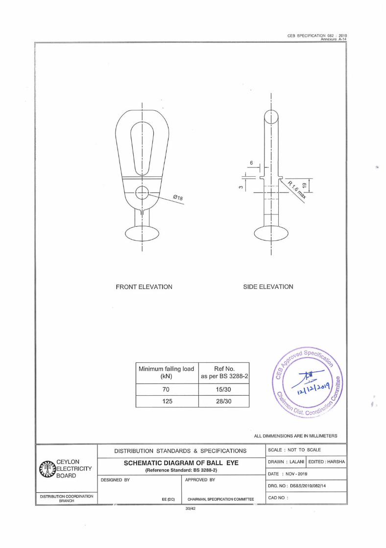
CEB SPECIFICATION 082 . 2019Annexure A-14
FRONT ELEVATION SIDE ELEVATION
Minimum failing load Ref No.(KN) as per BS 3288-2
70 15/30
125 28/30
ALL DIMMENSIONS AREIN MILLIMETERS
DISTRIBUTION STANDARDS & SPECIFICATIONS SCALE : NOT TO SCALE
CEYLON SCHEMATIC DIAGRAM OF BALL EYE DRAWN : LALANI|EDITED : HARSHA
ELECTRICITY (Reference Standard: BS 3288-2)BOARD DATE : NOV-2019
DESIGNED BY APPROVED BY
DRG. NO : DS&S/2019/082/14eo EE (0C) CHAIRMAN, SPECIFICATION COMMITTEECAD NO:
30/42

219pe Cotter Pin & Split Pin
CEB SPECIFICATION 082 - 2019Annexure A-15=
Slot for W security clip
Ex
Cotter Pin & Split Pin
SIDE ELEVATIONFRONT ELEVATION
Minimum Ref. No. Cotterfailing load|as per BS 3288-2|Pin size
(kN) (mm)
70 15/35 16
120 28/36A 20
Dashed line applied to28/36A only
ALL DIMMENSIONS AREIN MILLIMETRES
CEYLON
EedatectaciryBOARD
DISTRIBUTION STANDARDS & SPECIFICATIONS SCALE : NOT TO SCALE
SCHEMATIC DIAGRAM OF SOCKET EYE(Reference Standard: BS 3288-2)
DRAWN : LALANI | EDITED : HARSHA
DATE : NOV- 2019
DISTRIBUTION COORDINATIONBRANCH
DESIGNED BY APPROVED BY
EE (DC) CHAIRMAN, SPECIFICATION COMMITTEE CAD NO :
DRG. NO: DS&S/2019/082/15
31/42

CEB SPECIFICATION 082:2019
Annex — B1
SCHEDULE OF TECHNICAL REQUIREMENTS AND GURANTEED TECHNICAL PARTICULARS(This schedule shall be duly filled by the Manufacturer for each type of insulator offered for applicable parameters)
Properties of Material used for Insulators
Tougheneda)|Type Porcelain Silicon Rubber Glass
b)|Chemical Composition
c)|Porosity Volume %
d)|Bulk density g/cm3
e)|Fatigue strength N/mm?
f)|Tensile strength N/mm?
g)|Impact strength N/mm?
h)|Modulesofelasticity Gpa
i Mean Coefficient oflinear 40-8K-1thermal expansion
j)|Resistance to thermal shock|Kk)|Breakdown voltage kV/mm
1)|Dielectric constant tanm)|Resistivity Qm
Signature ofthe Manufacturer and seal _ "DateWecertify that the above data are true and correct
Signature of the Bidder and seal Date
32/42

CEB SPECIFICATION 082:2019
Annex — B2
SCHEDULE OF TECHNICAL REQUIREMENTS AND GURANTEED TECHNICAL PARTICULARS(This schedule shall be duly filled by the Manufacturer for each type of insulator offered)
(For Pin, Pin Post Insulators and Station Post /Applicable for item A, B & D)
Offered
ihe Type of the insulator offered
2. item Designation as per the Clause 1.0
3. Nameof the manufacturer
4. Country of origin
5: Rated voltage applicable kV i6. Rated frequency Hz
7 Applicable standards
8. Type of insulator material
9; Type of thimble material
10.|Rated withstand Voltages
(a) Lightning Impulse
(i) Positive Peak kV
(ii) Negative Peak kV
(b) 1 Minute Power Frequency(i) Wet kV
(ii) Dry kV
(c) Power frequency flash-over voltages(i) Wet kV
(ii) Dry kV
11.|Total creepage distance mm
12.|Creepage factor
13.|Minimum failing load kN
14 Applicable size of conductor (indicate the range of sizes of a*|conductors) / bus barsize15.|Radio interference noise level at standard test voltage dB
16.|Dry arcing distance of the complete units mm
17.|Overall height of the complete unit mm 6
18.|Minimum ratio of shed spacing to shed overhang
19.|Type of galvanizing & thicknessof coating20.|Colour of glazing/insulator21. Whether Pin Post Insulator supplied complete with necessary Pearthardware suchassteel pin, nuts and washers?22.|Whether the dimensional drawings of the item offered furnished? Yes/No
23.|Total weight LES9 %
33/42 e ae gSN Ayr"a oN

CEB SPECIFICATION 082:2019
Whethera certified copy of ISO 9001:2015 or latest furnished24.|with the offer? Yes/No
Whether the entire Type Test Certificates in accordance with28. clause 6.3 furnished with the offer? Yes/No
26.|Whether markings provided as per clause 11.2? Yes/No
Whether the information requested in clause 7 furnished withan. the offer? , Yes/No
Signature of the Manufacturer and seal Date
Wecertify that the above data are true and correct
CORR ee eee eee eee eee eee eRe EE REE E EE EEE OEE EERE E EEE eee eee eee ee eee ee
Signature of the Bidder and seal Date
34/42

CEB SPECIFICATION 082:2019
Annex — B3
SCHEDULE OF TECHNICAL REQUIREMENTS AND GURANTEED TECHNICAL PARTICULARS(This schedule shall be duly filled by the Manufacturer for each type of insulator offered)
(For Disc Insulator Units of Normal and Aerodynamic Profile /Applicable for item E & F)
Offered~s Profile type of the disc insulator offered
2. Item Designation as per the Clause 1.0
3.|Nameof the manufacturer4.|Country oforigin5.|Rated voltage applicable kV
6.|Rated frequency Hz
7.|Applicable standards
8.|Type of insulator material
9.|Porcelain diameter mm
10.|Insulator spacing mm
11.|Type of thimble material
12.|Rated withstand Voltages
(a) Lightning Impulse
(i) Positive Peak kV
(ii) Negative Peak kV
(b) 1 Minute Power Frequency(i) Wet kV
(ii) Dry kV
(c) Power frequency flash-over voltages(i) Wet kV
(ii) Dry kV
13.|Total creepage distance mm
14.|Creepage factor
15.|Minimum failing load kN
16.|Size of the ball & socket coupling
17.|Thicknessof zinc sleeve mm
18.|Purity of zinc sleeve %
19.|Zinc sleeve fused area %
20.|Whether W-Clips provided along with the insulator Yes/No
21.|Thickness of the W-Clip mm
22.|Radio interference noise level at standard test voltage dB
23.|Dry arcing distance of the complete units

CEB SPECIFICATION 082:2019
24.|Overall height of the complete unit mm
25.|Type of galvanizing & thickness of coating
26.|Colour of glazing/insulator
27.|Whether the dimensional drawings of the item offered furnished? Yes/No
28.|Total weight /
kg
Whethera certified copy of ISO 9001:2015 or latest furnished29.|with the offer? Yes/No
30 Whether the entire Type Test Certificates in accordance with Yes/No-|clause 6.3 furnished with the offer? a
31.|Whether markings provided as per clause 11.2? Yes/No
32. Whether the information requested in clause 7 furnished with Yes/Nothe offer?
Signature of the Manufacturer and seal
I/We certify that the above data are true and correct
nee RRR RETR E REE EE TEETER EERE REET EERE REET EEE ES
Signature of the Bidder and seal
36/42

CEB SPECIFICATION 082:2019
Annex — B4
SCHEDULE OF TECHNICAL REQUIREMENTS AND GURANTEED TECHNICAL PARTICULARS(This schedule shall be duly filled by the Manufacturer for each type of insulator offered)
(For Composite Pin Post and Tension Insulators/ Applicable for item C & G)
Offered
Type of the insulator offered
Item Designation as per clause 1.0
3.|Name of the manufacturer and countryof origin of:
(a) Core Rod
(b) Housing/ Whethershed
(c) Composite insulator
4.|Model/Reference/Catalogue number
5.|Rated voltage applicable kV
6.|Rated frequency Hz
7.|Applicable standards
8.|Materialof:(a) Core
(b) Housing and weathersheds
(c) Sealing material
9.|Rated withstand Voltages
(a) Lightning Impulse
(i) Positive Peak kV
(ii) Negative Peak kV
(b) 1 Minute Power Frequency(i) Wet kV
(ii) Dry kV
(c) Power frequency flash-over voltages(i) Wet kV
(ii) Dry kV
10.} Total creepage distance mm
11.] Creepage factor
12.| Minimum failing load kN
13. Applicable size of conductor (indicate the range of sizes of fritconductors)14.] Radio interference noise level at standard test voltage dB
15.| Dry arcing distance of the complete units mm
16.} Overall length of the complete unit mm
17.| Whether requirement no.of cotter pins andsplit pins provided? Yes/No} “08SPECiA
37/42

CEB SPECIFICATION 082:2019
~_ Minimum ratio of shed spacing to shed overhang= ©|& Type of galvanizing & thickness of coating if applicable
thease
accel
cl
ees
20.; Colour of insulator21., Whether the dimensional drawingsof the item offered furnished? Yes/No
22.| Total weightWhethera certified copy of ISO 9001:2015 or latest furnished23.1 with the offer? Yes/No
24 Whether the entire Type Test Certificates in accordance with Yes/No‘| clause 6.3 furnished with the offer?
25.| Whether markings provided as per clause 11.2? Yes/No
WhetherDesign Test Certificates in accordance with clause 6.426.| furnished with the offer? Yes/No
97. Whether the information requested in clause 7 furnished with Veeiiiethe offer?
Signature of the Manufacturer and seal
I/We certify that the above data are true and correct
Signature of the Bidder and seal
38/42

CEB SPECIFICATION 082:2019
Annex - B5
SCHEDULE OF TECHNICAL REQUIREMENTS AND GURANTEED TECHNICAL PARTICULARS(This schedule shall be duly filled by the Manufacturer for offered insulator hardware fitting as applicable. If there are
multiple manufacturers each should fill the schedule separately)
(For Insulator Hardware Fittings/ Applicable for item H, I, J, K, L, M, N, O, P,Q)
Offered
General Information
a) Name of the manufacturer
b) Country of origin
c) Whethera certified copy of ISO 9001:2015 orlatest furnished Vasowith the offer?
d) Whether the entire Type Test Certificates in accordance with Yes/Noclause 6.3 furnished with the offer?
Pins for 11kV/33kV Pin Insulatorsa) Item Designation as per the Clause 1.0
b) Applicable standards
c) Rated Voltage kV
d) Reference no. as per BS 3288-2
e) Shank length mm
f) Screwed length mm
g) Minimum failing load kN
h) Whether required nuts & washers provided? Yes/No
i) reneie dimensional drawings of the item offered Wasitio
j) Type of galvanizing & thickness of coating mm
k) Total weight kg
Bolted Clamps (Shackle Gun) for Tension Insulator Setsa) Item Designation as per the Clause 1.0
b) Applicable standards
c) Material composition used
d) Reference no. as per BS 3288-2
e) No of U bolts included
f) Type of conductor which can be accommodated(Raccoon / Lynx / Elm )
g) Minimum failing load kN
h) ee,= dimensional drawings of the item offered Yes/No
i) Total weight kg
Crimped Type Clampsfor Tension Insulator Sets eea) Item Designation as per the Clause 1.0 LSON

CEB SPECIFICATION 082:2019
b) Applicable standards
c) Material composition used——E
d) Reference no. as per BS 3288-2
e) Single part fitting or two part fitting as per clause 5.9?
od
f) Type of conductor which can be accommodated(Raccoon / Lynx / Elm / Zebra)
g) Minimum failing load kN
h) Whether the dimensional drawings of the item offeredfurnished? Yes/No
i) Total weight kg
Suspension Clamps
a) Item Designation as per the Clause 1.0
b) Applicable standards
c) Material composition used
d) Reference no. as per BS 3288-2
e) Type of conductor which can be accommodated(Raccoon / Lynx / Elm / Zebra)
f) Minimum failing load kN
g) Whether the dimensional drawings of the item offeredfurnished? Yes/No
h) Total weight kg
Anchor Shackle, Socket Eye and Ball Eye with Accessories
a) Applicable standards
b) Material composition used
c) Anchor Shacklei.|Reference no. as per BS 3288-2ii.|Minimum failing load
iii.|Whether required cotter pins and split pins provided? Yes/No
d) Socket Eyei. Reference no. as per BS 3288-2
ii.|Standard coupling size
ii.|Minimum failing load
iv.|Whether required W-Clips provided? Yes/No
v. Thickness of W-Clip mm
vi.|Whether required cotter pins and split pins provided? Yes/No
e) Ball Eye
i. Reference no. as per BS 3288-2
ii.|Standard coupling size
iii,|Minimum failing load
iv.|Whether required cotter pins and split pins provided? Ne

CEB SPECIFICATION 082:2019
f) Whether the dimensional drawings of the items offeredfurnished? Yes/No
Signature of the Manufacturer andseal DateWecertify that the above data are true and correct
ARRReeeee EERE EEE EEOEEE eee ee eee een ene
Signature of the Bidder and seal Date
41/42

CEB SPECIFICATION 082:2019
Annex — C
Non-Compliance Schedule
On this schedule the bidder shall provide a list of non-compliances with this specification,documenting the effects that such non-compliance is likely to have on the equipment life andoperating characteristics. Each non-compliance shall be referred to the relevant specificationclause.
Clause No. Non-Compliance
Ree eee ee eee eee ee eee eee e eee e Eee eee eee eee eee eee eee neene
Signature of the Manufacturer Date
Wecertify that the above data are true and correct
Signature of the Bidder and seal
42/42