scanning densitometer - x-rite photo we at x-rite, incorporated are proud to present you with the...
TRANSCRIPT

X-Rite® 381
Scanning Densitometer
Operation Manual

X-Rite, Incorporated----World Headquarters3100 44th St., S.W. • Grandville, Michigan 49418 • U.S.A.Tel: (616) 534-7663 • Order Administration Fax: (616) 534-0723Instrument Services Fax: (616) 534-7722
X-Rite GmbHCharlottenstraße 61 • 51149 Köln • DeutschlandTel: (49) 2203-91450 • Fax: (49) 2203-914519
X-Rite Asia Pacific Ltd. Room 1004-05 • Kornhill Metro Tower • 1 Kornhill Road Hong Kong • Tel: (852) 2-568-6283 • Fax: (852) 2-885-8610
X-Rite Ltd. Lower Washford Mill • Mill Street • Buglawton Congleton, Cheshire CW12 2AD • U.K. Tel: (44) 1260-279988 • Fax: (44) 1260-270696
P/N 381-500Rev. L-02/05/96

Congratulations!
We at X-Rite, Incorporated are proud to present you with theX-Rite 381 Scanning Densitometer. This instrument represents thevery latest in microcontrollers, integrated circuits, optics, anddisplay technology. As a result, your X-Rite 381 is a rugged andreliable instrument whose performance and design exhibit thequalities of a finely engineered instrument, which is not surpassed.
To fully appreciate and protect your investment, we suggest thatyou take the necessary time to read and fully understand thismanual. As always, X-Rite stands behind your 381 with a full oneyear limited warranty and a dedicated service organization. If theneed arises, please don’t hesitate to call us.
Thank you for your trust and confidence.
Ted ThompsonChairman of the Board, C.E.O.
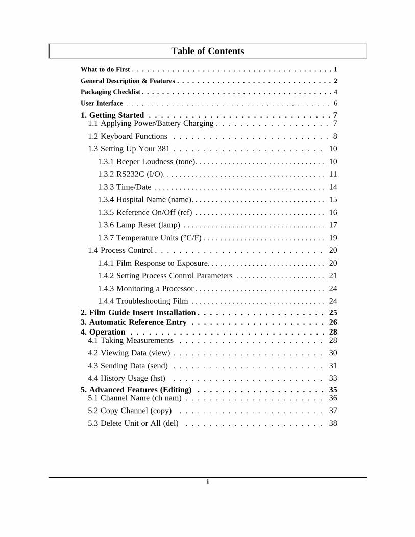
Table of Contents
What to do First . . . . . . . . . . . . . . . . . . . . . . . . . . . . . . . . . . . . . . . . 1
General Description & Features . . . . . . . . . . . . . . . . . . . . . . . . . . . . . . . 2
Packaging Checklist . . . . . . . . . . . . . . . . . . . . . . . . . . . . . . . . . . . . . . 4
User Interface . . . . . . . . . . . . . . . . . . . . . . . . . . . . . . . . . . . . . . . . . 6
1. Getting Started . . . . . . . . . . . . . . . . . . . . . . . . . . . . . . 71.1 Applying Power/Battery Charging . . . . . . . . . . . . . . . . . . . 71.2 Keyboard Functions . . . . . . . . . . . . . . . . . . . . . . . . . . 81.3 Setting Up Your 381 . . . . . . . . . . . . . . . . . . . . . . . . . 10
1.3.1 Beeper Loudness (tone). . . . . . . . . . . . . . . . . . . . . . . . . . . . . . . . 101.3.2 RS232C (I/O). . . . . . . . . . . . . . . . . . . . . . . . . . . . . . . . . . . . . . . . 111.3.3 Time/Date . . . . . . . . . . . . . . . . . . . . . . . . . . . . . . . . . . . . . . . . . . 141.3.4 Hospital Name (name). . . . . . . . . . . . . . . . . . . . . . . . . . . . . . . . . 151.3.5 Reference On/Off (ref) . . . . . . . . . . . . . . . . . . . . . . . . . . . . . . . . 161.3.6 Lamp Reset (lamp) . . . . . . . . . . . . . . . . . . . . . . . . . . . . . . . . . . . 171.3.7 Temperature Units (°C/F) . . . . . . . . . . . . . . . . . . . . . . . . . . . . . . 19
1.4 Process Control . . . . . . . . . . . . . . . . . . . . . . . . . . . . 201.4.1 Film Response to Exposure. . . . . . . . . . . . . . . . . . . . . . . . . . . . . 201.4.2 Setting Process Control Parameters . . . . . . . . . . . . . . . . . . . . . . 211.4.3 Monitoring a Processor . . . . . . . . . . . . . . . . . . . . . . . . . . . . . . . . 241.4.4 Troubleshooting Film . . . . . . . . . . . . . . . . . . . . . . . . . . . . . . . . . 24
2. Film Guide Insert Installation . . . . . . . . . . . . . . . . . . . . . 253. Automatic Reference Entry . . . . . . . . . . . . . . . . . . . . . . 264. Operation . . . . . . . . . . . . . . . . . . . . . . . . . . . . . . . . 28
4.1 Taking Measurements . . . . . . . . . . . . . . . . . . . . . . . . 284.2 Viewing Data (view) . . . . . . . . . . . . . . . . . . . . . . . . . 304.3 Sending Data (send) . . . . . . . . . . . . . . . . . . . . . . . . . 314.4 History Usage (hst) . . . . . . . . . . . . . . . . . . . . . . . . . 33
5. Advanced Features (Editing) . . . . . . . . . . . . . . . . . . . . . 355.1 Channel Name (ch nam) . . . . . . . . . . . . . . . . . . . . . . . 365.2 Copy Channel (copy) . . . . . . . . . . . . . . . . . . . . . . . . 375.3 Delete Unit or All (del) . . . . . . . . . . . . . . . . . . . . . . . 38
i

Table of Contents - continued
5.4 Aim Value (aims) . . . . . . . . . . . . . . . . . . . . . . . . . . 395.5 Control Limit (clim) . . . . . . . . . . . . . . . . . . . . . . . . . 405.6 Equation Setup (eqn) . . . . . . . . . . . . . . . . . . . . . . . . . 41
6. Maintenance . . . . . . . . . . . . . . . . . . . . . . . . . . . . . . . 486.1 Calibration Verification . . . . . . . . . . . . . . . . . . . . . . . 486.2 Troubleshooting Chart . . . . . . . . . . . . . . . . . . . . . . . . 496.3 Optics Cleaning . . . . . . . . . . . . . . . . . . . . . . . . . . . 506.4 Read Lamp Replacement . . . . . . . . . . . . . . . . . . . . . . 516.5 Nicad Batteries Replacement . . . . . . . . . . . . . . . . . . . . 52
Appendix . . . . . . . . . . . . . . . . . . . . . . . . . . . . . . . . . . 53A1 - Specifications . . . . . . . . . . . . . . . . . . . . . . . . . . . . 53A2 - Display Abbreviations . . . . . . . . . . . . . . . . . . . . . . . 54A3 - Error Messages . . . . . . . . . . . . . . . . . . . . . . . . . . . 55A4 - Factory Presets . . . . . . . . . . . . . . . . . . . . . . . . . . . 57A5 - Accessories . . . . . . . . . . . . . . . . . . . . . . . . . . . . . 58A6 - Serial Printer Configuration . . . . . . . . . . . . . . . . . . . . 59A7 - Setup Definition . . . . . . . . . . . . . . . . . . . . . . . . . . 63A8 - Proprietary Notice . . . . . . . . . . . . . . . . . . . . . . . . . 65A9 - Warranty . . . . . . . . . . . . . . . . . . . . . . . . . . . . . . 66
ii
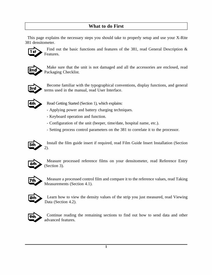
What to do First
This page explains the necessary steps you should take to properly setup and use your X-Rite381 densitometer.
Find out the basic functions and features of the 381, read General Description &Features.
Make sure that the unit is not damaged and all the accessories are enclosed, readPackaging Checklist.
Become familiar with the typographical conventions, display functions, and generalterms used in the manual, read User Interface.
Read Getting Started (Section 1), which explains:
- Applying power and battery charging techniques.
- Keyboard operation and function.
- Configuration of the unit (beeper, time/date, hospital name, etc.).
- Setting process control parameters on the 381 to correlate it to the processor.
Install the film guide insert if required, read Film Guide Insert Installation (Section2).
Measure processed reference films on your densitometer, read Reference Entry(Section 3).
Measure a processed control film and compare it to the reference values, read TakingMeasurements (Section 4.1).
Learn how to view the density values of the strip you just measured, read ViewingData (Section 4.2).
Continue reading the remaining sections to find out how to send data and otheradvanced features.
1

General Description & Features
Description
The X-Rite 381 Densitometer is an automatedtransmission instrument designed for the qualitycontrol of 21 step, sensitometric film stripsexposed by an X-Rite Sensitometer.
Film strips are automatically measured using amotorized control mechanism. Data is sorted andavailable for viewing or transmitting via theRS232 port.
The densitometer is operated using 4 keys and ainteractive 16 character/2-line Liquid CrystalDisplay. There are 16 channels for differentprocessor monitoring. The unit saves the last 32strips measured for each channel. Each strip measured includes 21 steps of density, time/date,and one manually entered temperature.
Reference data can be manually or automatically entered.
The densitometer measures and stores the absolute density of the steps. In addition, you canview the data as deviated from the reference values.
The densitometer comes preset with common process control equations for interpreting thedata. Basic equations types are:
- Density at step number.- Density at exposure level.- Exposure level at density.- Contrast.- Gradient.
The densitometer has an Editor that allows you to set the Aim Value, Control Limit, ChannelName, and Equation format to best suit your individual requirements. The Editor also allowsyou to copy the setup of one channel to another channel. This is useful when you have two ofthe same type processors. You may also delete an individual unit or the entire database of achannel using the Editor.
Setting the Aim values and Control limits informs the densitometer when to display Go/NoGo indications. After each measurement the unit will display if the limits were exceeded.
The densitometer can output to a dot matrix serial printer a sensitometric curve report or aclothes-line plot of three user defined equations along with temperature.
FILM INLET
KEYS
DISPLAY
2

General Description & Features - continued
Features:
- Automated measurement of 21- step sensitometric control strips (8" and larger).- 16 separate processor channels.- Stores last 32 strips for each channel.- 21 steps of density, processor temperature, time, and date is saved for each strip
measured.- Six user definable fields to interpret data.- Print out of sensitometric curve (density vs. exposure) for last strip measured.- Clothes-line plot for three of the user defined fields plus temperature.- Display of density at step number.- Automatic Data sorting- Automatic calibration. - Simple 4-key operation.- Six rechargeable AA 1.2v NiCad batteries.- External battery charger/eliminator.- 16 character by two line, supertwist (Hi Contrast) LCD display.- Control violations may be displayed for each strip measured to provide quick
Go/No Go indication.- RS232 output for RCI, computer, printer, or block I/O formats, with selectable
Baud rates. For more information on RS232C and RCI protocol, order the 380Series RS232C Interface Manual from X-Rite (P/N 380-506).
3

Packaging Check List
After removing the instrument from the shipping carton, inspect for possible damage. If anydamage is noted, contact the transportation company immediately. Do nothing more until thecarrier’s agent has inspected the damage.
If damage is not evident, check and make sure that all items are included (Refer to the parts listbelow, and the following page for the packaging illustration).
Your 381 Densitometer was packaged in a specially designed carton to assure against damage.If reshipment is necessary, the instrument should be packaged in the original carton. If the originalcarton is not available, a new one can be obtained from X-Rite, Incorporated. Refer to the packagingdrawing on the following page.
4

PACKING ILLUSTRATION
5

User Interface
This section will explain the typographical conventions, display functions, and general termsused in this manual.
» The characters in the display above each key dictate whichfunction will be selected or what action will take place when thatkey is pressed.
» Information that will appear in the display will be printed in themanual with arrow marks on each side and in boldface. Ex.,<MEASURING STRIP>
» General messages and information telling you what channel,menu , etc. you have active are displayed in uppercase letters.Lowercase letters represent functions that can be activated,changed, etc.
» When a key is to be momentarily pressed, it will be printed inthe manual with brackets on both sides and in boldface. Ex.,[P1]. Note, in the illustration the function will have a white boxaround it and the key to be pressed will be tinted.
» The symbols ↑ and ↓ represent the arrow symbols in the displayused in the various edit functions. Pressing [↑] key incrementsand [↓] key decrements thru a list of numbers, letters, or symbolsavailable for that function.
» The term "cursor" is a black line that will appear below acharacter in the display. In most cases it means that character isactive and can be edited via the [↑] and [↓] keys. The symbol →advances the cursor to the next character to edit.
» When a procedure is continued on the next page an arrow willappear in the bottom right hand corner of the page.
» Important notes will be indicated with a hand pointing at themessage.
» The term "Channel" is a quality control record of up to 32 measurements of density data. Aletter (A thru L) is displayed to indicate which channel is being used. Ex., [CH:A]
» The term "Channel Name" is a user defined 10 character name which identifies theprocessing unit being monitored.
» The term "Equation" is a building block which allows the user to customize the fields tomeet their application.
» The term "Field" is a display which shows the density data interpreted by an equation.Fields can be named, defined by an equation, and the equations can be given values thatdescribe where the equation is to be applied. Ex.,
B(ase)+Fog {it’s name} = Density @ step one {it’s equation & value}
CH:A
send view hst
MAIN MENUp1
MEASURING STRIP
CH: A Xray lab A
exit
CH: A
exit
Xray lab A
p2 edit ref
CH:A MAIN MENU
GENERAL INFORMATION
FUNCTIONS
s upET
CH:A MAIN MENU
send view hstp1
6

1. Getting Started
1.1. Applying Power/ Battery Charging
Applying Power
During battery operation power is applied when any key ispressed. The unit will automatically power down after twominutes of non-use (no keys pressed or measurements taken).
When the AC adaptor is connected the unit will not powerdown.
When the unit is awakened from a power down condition adiagnostics procedure is performed, and then the main menuis displayed.
Battery Charging
Before using: Make sure the voltage indicated on the AC adaptor complies with the AC linevoltage in your area. If not contact your dealer.
1. Plug the small connector end of the adaptor into side of unit.
2. Plug line cord end of adaptor into AC wall outlet.
3. Unit should be fullycharged in 14 hours.Note: If your unit has notbeen used for severalweeks recharge forapproximately 24 hours.
› The unit should be charged before use. The unit can be operated while the batteries arebeing charged.
CH:A
p1
MENUCHAN
send view hst
MAIN MENU
Process Control Densitometer
Software VXXXXSelftest = PASS
METROPOLITANHOSPITAL
Copyright 1989X-Rite, Inc.
7

1.2 . Keyboard Functions
The characters in the display above each key dictate which function will be selected or whataction will take place when that key is pressed.
The main menu is contained in two pages. To advance to the next page press [p1] or [p2].
send - allows you to transmit data out the RS232 port.
view - allows you to view the last strip measured. The data is contained in four different pages.
hst - allows you to view or print the previous strips measured in the database. The databasecan hold up to 32 different readings for each channel.
edit - allows you to to set the Aim Value, Control Limit, Channel Name, and Equation formatto best suit your individual requirements. The Editor also allows you to copy the setup of onechannel to another channel. This is useful when you have two of the same type processors. Youmay also delete an individual unit or the entire database of a channel using the Editor.
setup - allows you to set the tone, I/O parameters, time/date, hospital name, references, lampmonitor and temperature format.
ref - allows automatic entry and averaging of reference data by measuring reference films.
CH:Asend view hst
MAIN MENUp1
CH:A
MENUCHAN
send view hstMAIN MENU
p1
CH:A MAIN MENU
edit refp2 s upET
8
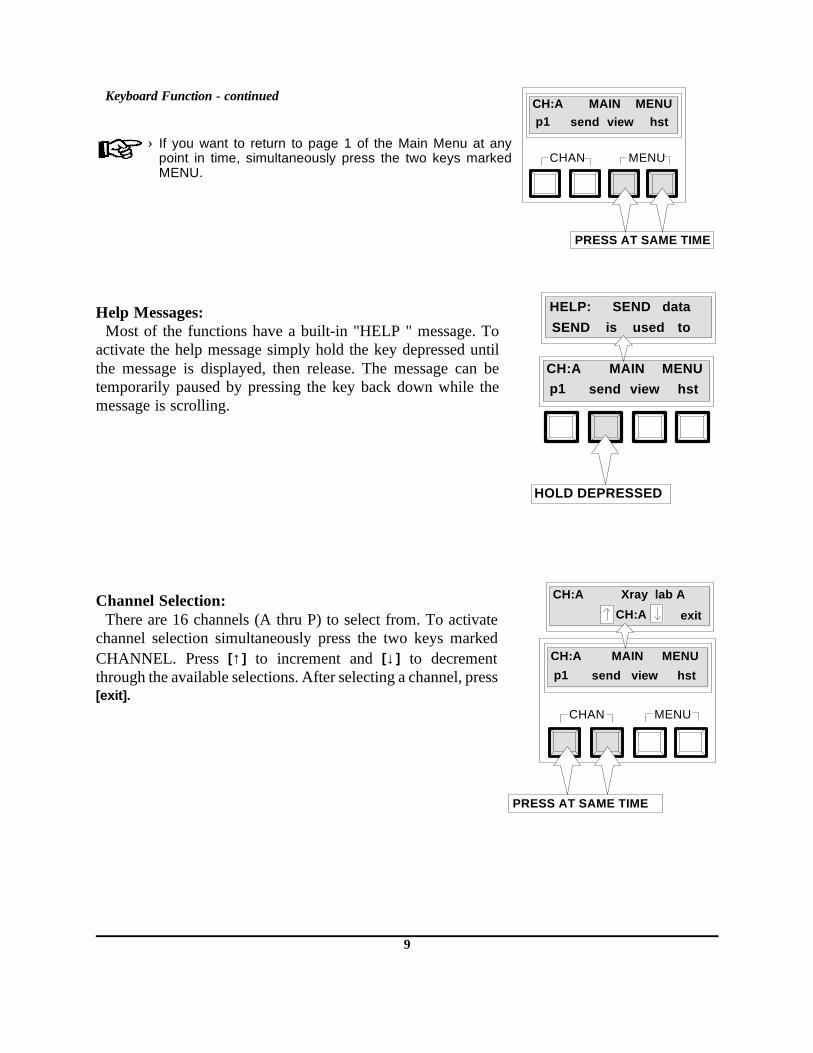
Keyboard Function - continued
› If you want to return to page 1 of the Main Menu at anypoint in time, simultaneously press the two keys markedMENU.
Help Messages:Most of the functions have a built-in "HELP " message. To
activate the help message simply hold the key depressed untilthe message is displayed, then release. The message can betemporarily paused by pressing the key back down while themessage is scrolling.
Channel Selection:There are 16 channels (A thru P) to select from. To activate
channel selection simultaneously press the two keys markedCHANNEL. Press [↑] to increment and [↓] to decrementthrough the available selections. After selecting a channel, press[exit].
CH:A
MENUCHAN
send view hstMAIN MENU
p1
PRESS AT SAME TIME
CH:Asend view hst
MAIN MENUp1
HOLD DEPRESSED
SEND HELP:SEND
data is used to
CH:A
MENUCHAN
send view hst
MAIN MENU
p1
PRESS AT SAME TIME
CH:A Xray lab A
CH:A exit
9
1.3. Setting Up Your 381
Your 381 should be setup (tone, date/time, etc.) before proceeding to reference entry orstrip measurement. The procedures for setting up the unit are shown on the following pages.Refer to Appendix A7 for 381 setup definition.
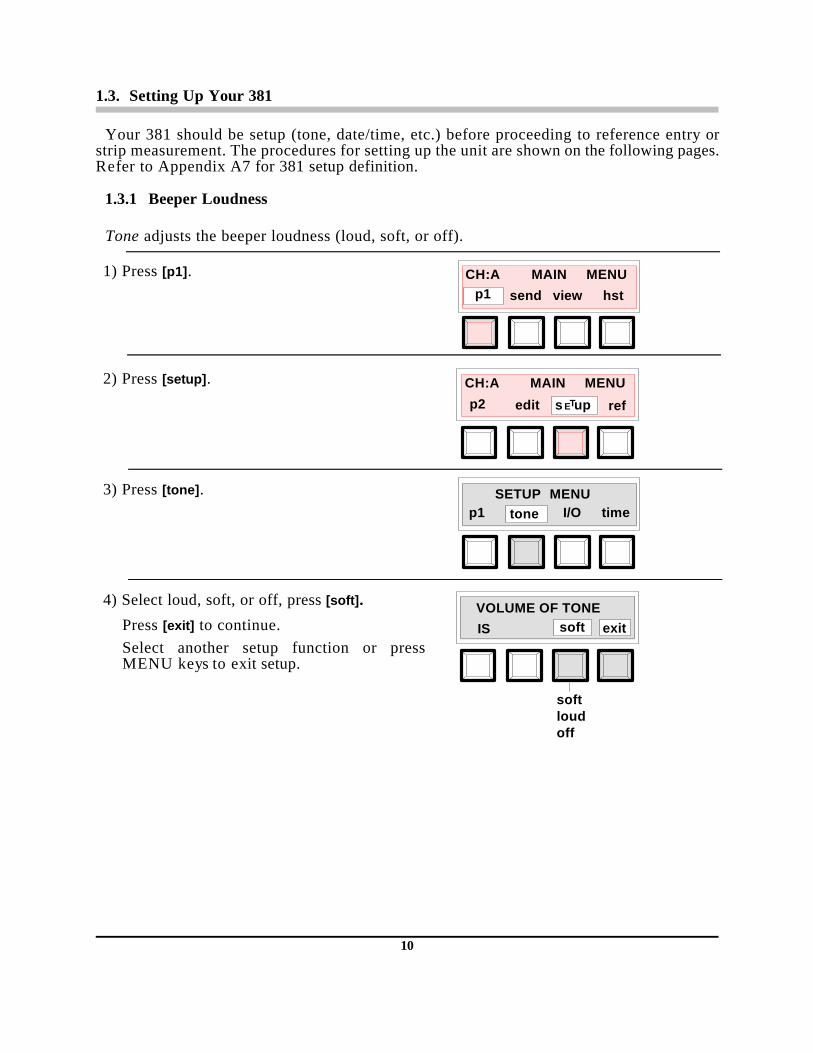
1.3.1 Beeper Loudness
Tone adjusts the beeper loudness (loud, soft, or off).
1) Press [p1].
2) Press [setup].
3) Press [tone].
4) Select loud, soft, or off, press [soft].
Press [exit] to continue.Select another setup function or pressMENU keys to exit setup.
CH:A
send view hst
MAIN MENUp1
CH:A MAIN MENU
refp2 s upETedit
SETUP MENUtimeI/Op1 tone
VOLUME OF TONEIS soft exit
softloud off
10

1.3.2 RS232C Setup
I/O allows you to set the RS232 parameters of the I/O port. You can select a preset setting(ex. Epson serial printer) and the 381 will preset all the necessary I/O parameters; or custom,where you have to individually set the I/O parameters (ex. baud, pin-5, format, etc). Referto Appendix A7 for preset and custom parameter definitions.
1) Press [p1].
2) Press [setup].
3) Press [I/O].
4) Select [preset] or [custom].
If preset is selected go to Step 5.If custom is selected go to Step 6.
5) Select output format, press [Epson].
Press [load] to save selected preset and exitout of I/O preset, or press [exit] to not saveselected preset and exit out of I/O preset.Select another setup function or press theMENU keys to exit setup.
CH:A
send view hst
MAIN MENUp1
CH:A MAIN MENU
refp2 s upETedit
SETUP I/O MENU
ORpreset custom
SETUP MENUtimep1 I/Otone
PRESET I/O MENUEpson
EpsonDiconixSeikoD.I.F.
load
301
exit
180si
11

RS232C Setup - continued
6) Select the baud rate, press [= 9600].
Press [baud] to go to next setup option (Step7) or press [save] to exit setup.
7) Select the status of pin-5, press [= cts].
Press [pin-5] to go to next setup option (Step8) or press [save] to exit setup.
8) Select the format status, press [= new].
Press [format] to go to next setup option(Step 9) or press [save] to exit setup.
9) Select the R.C.I. status, press [= off].
Press [r.c.i.] to go to next setup option (Step10) or press [save] to exit setup.
10) Select the decimal point status, press [= on].
Press [dec.pt.] to go to next setup option(Step 11) or press [save] to exit setup.
CUSTOM I/O MENU
save
Next 3006001200240048009600
Save & Exit
baud = 9600
CUSTOM I/O MENU
save
Save & ExitNext ctsbusyoff
pin - 5 = cts
CUSTOM I/O MENU
saveformat
Save & ExitNext newold
= new
CUSTOM I/O MENU
saver.c.i.
Save & ExitNext offon
= off
CUSTOM I/O MENU
savedec.pt.
Save & ExitNext offon
= on
12

RS232C Setup - continued
11) Select the delimiter status, press [= crlf].
Press [cr] to go to next setup option (Step 12)or press [save] to exit setup.
12) Select the comp status, press [= off].
Press [comp] to go to next setup option (Step13) or press [save] to exit setup.
13) Select the xmit status, press [= man].
Press [xmit] to go to next setup option (Step14) or press [save] to exit setup.
14) Select the width status, press [= full].
Press [width] to return to Step 6 or press[save] to exit custom setup.Select another setup function or pressMENU keys to exit setup.
CUSTOM I/O MENU
save
Save & ExitNext crlfcr
= crlfcr
CUSTOM I/O MENUsave
Save & ExitNext onoff
= offcomp
CUSTOM I/O MENUsave
Save & ExitNext man.auto
= man.xmit
CUSTOM I/O MENUsave
Save & ExitNext fullhalf
= fullwidth
13

1.3.3 Time / Date Setup
Time allows you to set the time and date.
1) Press [p1].
2) Press [setup].
3) Press [time].
4) Enter the date and the time.
Press [→] to move cursor to next characterPress [↑ ] to increment the number.Press [↓ ] to decrement the number.Press [save] to exit.Select another setup function or pressMENU keys to exit setup.
CH:A
send view hst
MAIN MENUp1
CH:A MAIN MENU
refp2 s upETedit
SETUP MENUp1 I/O timetone
05 / 10 / 89 09:12save
Cursor Save & ExitUp Down
14

1.3.4 Name Setup
Name allows you enter the name of the unit (ex., Metropolitan Hospital). The name willbe printed with the clothesline plot and characteristic curve each time they are transmitted.
1) Press [p1]
2) Press [setup].
3) Press [p1].
4) Press [name].
5) Enter the first line of the name (up to 16characters).
Press [→] to move cursor to next characterPress [↑ ] to increment thru the character list.Press [↓ ]to decrement thru the character list.Press [save] to continue.
6) Enter the second line of the name (up to 16characters).
Press [save] to exit. Select another setup function or pressMENU keys to exit setup.
CH:A
send view hst
MAIN MENUp1
CH:A MAIN MENU
refp2 s upETedit
SETUP MENUtimeI/Op1 tone
SETUP MENUrefsp2 name
save
Cursor Save Up Down
METROPOLITAN
save
Cursor Save & Exit Up Down
HOSPITAL
15

1.3.5 Reference Setup
Ref allows you to turn references on or off. If references are on, the densitometer will displayif the limits were exceeded after each measurement. Also, when you enter view or historyyou are prompted to select either meas (measured) or dev (deviated from reference). Ifreferences are off, limit violation is not displayed and you are not prompted to select eithermeas or dev in the view or history functions.
1) Press [p1]
2) Press [setup].
3) Press [p1].
4) Press [ref].
5) Select reference on or off, Press [on].
Press [exit] to continue.Select another setup function or pressMENU keys to exit setup.
CH:A
send view hst
MAIN MENUp1
CH:A MAIN MENU
refp2 s upETedit
SETUP MENUtimeI/Op1 tone
SETUP MENUp2 name refs
REFERENCES ARE
ALWAYS exiton
ONOFF
16

1.3.6 Lamp Counter Reset
Lamp allows you to view the lamp life percentage and reset the lamp hours back to zero.This reset should only be done after replacing the lamp.
1) Press [p1].
2) Press [setup].
3) Press [p1].
4) Press [p2].
5) Press [lamp].
6) Press [reset] to reset counter or press [exit] to exit without resetting counter.
If [reset] is pressed go to Step 7.
› If either [reset] or [exit] is pressed < CALIBRATING LAMP DRIFT> will display for approx.20 seconds.
CH:A
send view hst
MAIN MENUp1
CH:A MAIN MENU
refp2 s upETedit
SETUP MENUtimeI/Op1 tone
SETUP MENUname refsp2
SETUP MENUp3 lamp C/Fo
LAMP = 20% of NEW
or exitreset
17

Lamp Counter Reset - continued
7) Select [yes] to reset lamp or [no].
If yes is selected "Lamp Monitor Reset to100%" is displayed.If no is selected "Lamp Monitor NotAffected" will display.Select another setup function or pressMENU keys to exit setup.
INSTALLED NEW
LAMP? yes no
18

1.3.7 Temperature Units (°C/F)
°C/F allows you to select the temperature format to be used (celsius or fahrenheit). › If the temperature format is changed after data has been entered, temperature data becomes
invalid and should be deleted using thedelete function (see Section 5.3.).
1) Press [p1].
2) Press [setup].
3) Press [p1].
4) Press [p2].
5) Press [°C/F].
6) Press [fahrenheit] to select temperature incelsius or fahrenheit.
Press [exit] to continue.Select another setup function or press theMENU keys to exit setup.
CH:Asend view hst
MAIN MENUp1
CH:A MAIN MENU
refp2 s upETedit
SETUP MENUtimeI/Op1 tone
SETUP MENUname refsp2
SETUP MENUp3 lamp C/Fo
TEMP. DISPLAYED INexitfahrenheit
CelsiusFahrenheit
19

1.4. Process Control
1.4.1 Film Response to Exposure
The 381 densitometer measures film exposed by all X-Rite sensitometers with 21 steps. Thesensitometer exposes film with a known quantity of light through a 21-step light modulator.The maximum light is emitted from Step No. 21. Each successive step emits 70.7% of thelight emitted from the step adjacent to it (.15 log exposure). The film responds to this exposurein a predictable way called the D-Log E Curve, (Density-Log Exposure Curve). Figure Oneshows the response of a typical radiographic film exposed by a sensitometer. The portion ofthe curve that changes most with variations in processing is called the "straight line portion"of the curve.
It is not necessary to plot D-Log E Curves to monitor automatic processors in normallaboratory environments. A simpler method is to record the three values (base+ fog, speedindex, & contrast index) on the D-Log E Curve which contain most of the data.
0.0
0.5
1.0
1.5
2.0
2.5
3.0
FILM
DENSI
TY
RELATIVE LOG EXPOSURE
0.0 0.3 0.6 0.9 1.2 1.5 1.8 2.1 2.4 2.7 3.0 3.3.15 .45 .75 1.05 1.35 1.65 1.95 2.25 2.55 2.85 3.15
CONTRAST INDEX
BASE+ FOG
SPEED INDEX
Figure 1. D-Log E Curve
20
Film Response to Exposure - continued
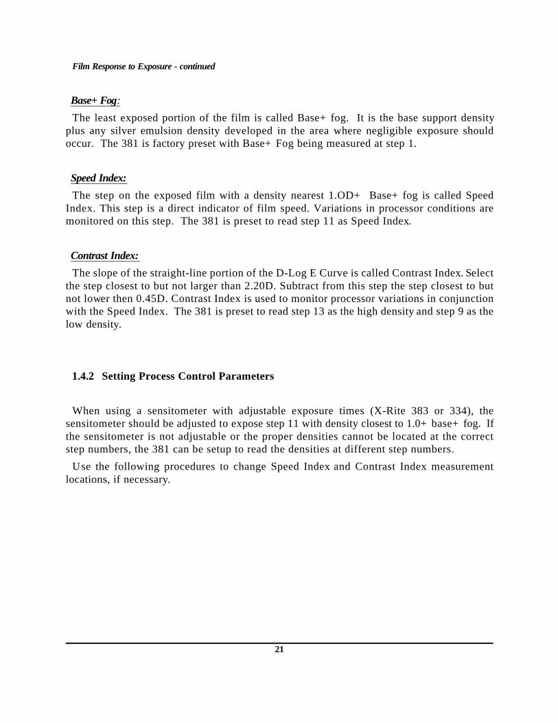
Base+ Fog:
The least exposed portion of the film is called Base+ fog. It is the base support densityplus any silver emulsion density developed in the area where negligible exposure shouldoccur. The 381 is factory preset with Base+ Fog being measured at step 1.
Speed Index:
The step on the exposed film with a density nearest 1.OD+ Base+ fog is called SpeedIndex. This step is a direct indicator of film speed. Variations in processor conditions aremonitored on this step. The 381 is preset to read step 11 as Speed Index.
Contrast Index:
The slope of the straight-line portion of the D-Log E Curve is called Contrast Index. Selectthe step closest to but not larger than 2.20D. Subtract from this step the step closest to butnot lower then 0.45D. Contrast Index is used to monitor processor variations in conjunctionwith the Speed Index. The 381 is preset to read step 13 as the high density and step 9 as thelow density.
1.4.2 Setting Process Control Parameters
When using a sensitometer with adjustable exposure times (X-Rite 383 or 334), thesensitometer should be adjusted to expose step 11 with density closest to 1.0+ base+ fog. Ifthe sensitometer is not adjustable or the proper densities cannot be located at the correctstep numbers, the 381 can be setup to read the densities at different step numbers.
Use the following procedures to change Speed Index and Contrast Index measurementlocations, if necessary.
21

Speed Index Step Selection
Select the channel to edit (refer to Sec. 1.2 for channel selection)
1) Press [p1].
2) Press [edit].
3) Press [p1].
4) Press [eqn].
5) Press [value].
6) If < S.Indx= > is not displayed, press field selectionkey until it is.
Press [edit] after selecting the Speed Index field.
7) Enter the desired step# for speed index.
Press [↑ ] to increment number.
Press [↓ ] to decrement number.
Press [save].
Press the two MENU keys to exit to Main Menu.
CH:A MAIN MENU
send view hstp1
CH:A MAIN MENU
refp2 edit Ts upE
EDITOR MENU
delp1 copynamch
EDITOR MENU
aimsp2 clim eqn
CH:A EDIT EQN
field exitvalue
CH:A EDIT VALUE S.Indx= D@S edit
FieldSelect
ENTER D@S STEP#11step = save
22

Contrast Index Hi & Lo Step Selection
Select the channel to edit (refer to Sec. 1.2 forchannel selection)
1) Press [p1].
2) Press [edit].
3) Press [p1].
4) Press [eqn].
5) Press [value].
6) If < C.Indx= > is not displayed, press field selectionkey until it is.
Press [edit] after selecting the Contrast Index field.
7) Enter the desired step# for Low density.
Press [↑ ] to increment number.
Press [↓ ] to decrement number.
Press [save].
8) Enter the desired step# for Hi density.
Press [↑ ] to increment number.
Press [↓ ] to decrement number.
Press [save].
Press the two MENU keys to exit to Main Menu.
CH:A MAIN MENU
send view hstp1
CH:A MAIN MENU
refp2 edit Ts upE
EDITOR MENU
delp1 copynamch
EDITOR MENU
aimsp2 clim eqn
CH:A EDIT EQN
field exitvalue
CH:A EDIT VALUE C.Indx= Cont edit
FieldSelect
ENTER Cont Hi -S#13step = save
ENTER Cont Lo-S#09step = save
23

1.4.3 Monitoring a Processor
The 381 can monitor a processor on each of its 16 channels (A thru P). The channel nameswhich appear on the print-outs are preset to "Xray Lab A" thru "Xray Lab P." These tencharacter names may be changed if desired (refer to Section 5.1 Channel Name of theAdvanced Users Section).
Reference Entry
Aim values for Base+ Fog, Speed Index, and Contrast Index must be established for eachprocessor being monitored. This is done automatically by measuring several (3-5) referencestrips that are exposed and processed when the processor is operating in an optimumfashion. Refer to Section 3 for the procedure on measuring the reference strips.
Running Daily Strips
Control Strips should be processed and measured daily. The 381 will automatically measurethe 21 densities, calculate the process control parameters, and indicate whether or not themeasured strip is within control limits. Refer to Section 4.1 for procedure on measuring strips.
Viewing or Plotting History
History allows you to view all the information on each strip in the database, or print theprocess control record. When the process control record is printed, processor and filminformation must be manually recorded at the top of the form (see example of printer plotat the end of Section 4.4, History Usage).
A box of film should be set aside from regular stock for exclusive process monitoring. Newfilm stock will require measuring new reference strips, because small density changes arepossible between film batches.
› One new set of references may be entered for each data set (32 measurements). The date thenew references are entered will be indicated on each field of the process control record as avertical dotted line. The corresponding new aim value will also be printed below each field.
› No more than two sets of references may be entered for each data set (32 measurements) orinvalid history plot data will result.
1.4.4 Troubleshooting Film
You should always keep Channel "P" of your unit open so that it can be used as a "scratchpad" when troubleshooting a processor. This will allow you to run film strips and correct theprocessor problem without interfering with the monitoring channels.
The following procedure is recommended for troubleshooting out-of-tolerance processors.
1. Copy the channel being monitored to Channel "P" (refer to Section 5.2 to copy eqn, name,ref, and data).
2. Measure films on Channel "P" and adjust processor as required.
3. When the processor is back in control measure a film on the original channel to verifycorrection.
24

2. Film Guide Insert Installation
The film guide insert must be installed if the X-Rite model 303, 333, or 334 sensitometerwas used to expose the film being measured.
- Install film guide insert by sliding into slot just above 35mm film guide (right hand side),see below.
Film Guide Insert
FRONT VIEW
Film Guide Insert Slot35mm Film Guide
25

3. Automatic Reference Entry
The Automatic Reference Entry procedure is the recommended method of entering inreference values. This method will average the reference films measured and load all 21steps of reference data (aim values) and entry of a reference processor temperature.
› To provide a better overall average, it is recommended to read five reference strips.
› The reference temperature is the center temperature which appears on the history plot. It isnot an aim value used for determining control limits.
3.1. Read - Automatic Reference Entry
1) Press [p1].
2) Press [ref].
3) Read the 1st reference strip. (See Section 4.1for proper film insertion technique.)
› Press [abort] to end the procedure withoutentering any reference data.
4) Read the 2nd reference strip.› Press [exit] if you do not want to read the
2nd strip and end the procedure.
5) Read the 3rd reference strip.› Press [exit] if you do not want to read the 3rd
strip and end the procedure.
CH:A MAIN MENU
send view hstp1
CH:A MAIN MENU
edit refp2 s upET
CH:A READ REF
STRIP #1 abort
CH:A READ REF
STRIP #2 exit
CH:A READ REF
STRIP #3 exit
26

Read - Automatic Reference Entry - continued
6) Read the 4th reference strip.
› Press [exit] if you do not want to read the 4thstrip and end the procedure.
7) Read the 5th reference strip.› Press [exit] if you do not want to read the
5th strip and end the procedure.
8) Press [↑ ] to increase or [↓ ] to decreasetemperature. Press [go] to continue to nextscreen.
After measuring the last strip < NEWREFERENCE INSTALLED> is momentarilydisplayed and the unit returns to Step 2 (Mainmenu - p2).
CH:A READ REF
STRIP #4 exit
CH:A READ REF
STRIP #5 exit
CH:A RECORD TEMP
go95.0F =
NEW REFERENCEINSTALLED!
27

4. Operation
4.1. Taking Measurements
› When inserting strips into unit, there must be at least a 1.1 inch (28mm) leader before theoutside edge of the first step. Refer to your Sensitometer Operation Manual for the propermethod for exposing film.
› When measuring single emulsion films, insert the strip with the emulsion side down.
› Before measuring, inspect the film for any pin spots or flaws on the 21 steps. If there is a flawor spot on a step, it could cause an inaccurate measurement.
› The exposed film must have a sensitometric exposure with a gamma of .7 or greater on steps7 thru 15. There must be a visible density difference between each step (density mustincrease by at least .11D between those steps).
› To ensure accurate measurement results, step 1 of the film must be inserted into thedensitometer first (low density end) if the film was exposed with an X-Rite 303/333 or aCronex® sensitometer.
1) For Sheet type film: Position the side of the strip with the exposed steps tightly up to the stop,then insert film (emulsion side down for single emulsion film) until it rests against the driverollers and the motor is activated. Do not release the film, with slight pressure continually holdthe film against the stop (guiding it to prevent any skewing) while the film is being measured.For Cine type film: Insert film (emulsion side down) into 35mm slot under the film guideuntil it rests against the drive rollers, and release when the motor takes hold.
› If the X-Rite model 303, 333, or 334 sensitometer was used to expose the film, the film guideinsert must be installed in the 381 to allow for proper film positioning (see Section 2). Cine filmexposed on the 303, 333, or 334 must also be guided against the insert (same as sheet film).
Sheet Type Cine Type
Guide the film (with slight pressure) on this side while it is being measured.
Cronex® is a registered trademark of E. I. Dupont De Nemours & Co.
28

Taking Measurements - continued
2)< MEASURING STRIP> and then < PROCESSING DATA> ismomentarily displayed.
› If < INVALID READING> is displayed, it means that theunit was not able to recognize all 21 steps. It does notmean that the limits were exceeded. Insert film again, ifstill not recognized, refer to Appendix A3 for moreinformation.
3) Select the channel you want to store the data in usingthe [↑ ] or [↓ ]. Press [go] to advance to next step.
4) The time and date are momentarily displayed. › If references are entered the unit will momentarily
display < WITHIN LIMITS> or < LIMITS EXCEEDED> .
5) The unit prompts you to enter the temperature of theprocessor solution, using the [↑ ] or [↓ ]. Press [go] tostore data and advance to next step.
6) Select [meas.] (actual measured data) or [dev.] (deviatedfrom reference). Ignore this step if reference is turnedoff in setup.
7) Press [p1] thru [p4] to view the measured data. Refer tosection 4.2 for further information on viewing data.
Press the two MENU keys to exit to Main Menu.
MEASURINGSTRIP
PROCESSINGDATA
CH:A X-ray lab
CH:A go
CH:A Time=02:00Date=1/12/89
CH:A RECORD TEMP
F= 95.0 go
CH:A S.Indx =0.98C.Indx =1.52p1
CH:A VIEW
meas. OR dev.
29

4.2. Viewing Data
After a film is measured, all 21 steps of density are stored in memory. View allows you to viewthe 21 density values, gamma (slope of the curve at density value) at .1D increments, and six userdefinable fields. These values can be viewed as measured or deviated from the references. Fields1-6 are preset with common process monitoring equations (see Appendix A4, Factory Presets).
› Disregard steps 1 and 2 if you are viewing data directly after a measurment.
1) Press [view].
2) Press [meas] or [dev.].› If reference is turned OFF in setup, skip this step.
3) Speed Index and Contrast Index values aredisplayed.
Press [p1].
4) Base+ Fog and Density Maximum values aredisplayed.
Press [p2].
5) Average Gradient and Gamma values aredisplayed. Other gamma values may be viewed bypressing [↑ ] to increase or [↓ ] to decrease densityvalue.
Press [p3].
6) Temperature and density step values are displayed.Other density step values may be viewed bypressing [↑ ] to increase step number or [↓ ] todecrease step number.
Press [p4] to return to page 1, or press the twoMENU keys to exit view and return to Main Menu.* Permanent fields are not user definable.
› Temperature will always appear as absolute temperature even if [dev] is pressed.
CH:A
send hst
MAIN MENUp1 view
CH:A VIEW
meas. OR dev.
CH:A S.Indx. =0.28
C.Indx =2.34p1
FIELD 1
FIELD 2
B+Fog =0.13Dmax =2.60
CH:Ap2
FIELD 3
FIELD 4
CH:Ap4
Temp F =95.0Den#01 =0.13
Increments/Decrements thru steps 1-21
.
FIELD6
* PERMANENTFIELD
CH:Ap3
Av. Grd [email protected] =0.13
Increases/Decreases the density at whichgamma is calculated. The densitychanges in 1/10th increments.
FIELD 5
* PERMANENTFIELD
30

4.3. Sending Data
Send allows you to manually transmit the last measurement taken to a printer. You canselect print (sends the 21 density steps), or plot (sends the characteristic curve). The datatransmitted is dependant on the printer selected (see Section 1.3.5). Refer to Appendix A6for serial printer setup and connection.
1) Press [send].
2) Press [print] or [plot].
If [print] was pressed, see print example below.If [plot] was pressed, see plot example onfollowing page.
Print Example
CH:A
view hst
MAIN MENU
p1 send
CH:A
OR
SEND
SENDING DATA
CH:A 03/20 15:13
CHANNEL DATE TIME
plot
Press print or plot
step 01 = 0.15
step 02 = 0.15
step 03 = 0.15
step 04 = 0.15
step 05 = 0.16
step 06 = 0.17
step 07 = 0.20
step 08 = 0.27
step 09 = 0.49
step 10 = 0.94
step 11 = 1.44
step 12 = 1.83
step 13 = 2.15
step 14 = 2.37
step 15 = 2.57
step 16 = 2.71
step 17 = 2.78
step 18 = 2.89
step 19 = 2.94
step 20 = 3.02
step 21 = 3.06
31

Plot Example
X-RITE Process Control DensitometerMETROPOLITAN
HOSPITAL---------------------------------------------------------------------------------------------------------
LOCATION: Xray lab A EXPOSURE DATE: XX/XX/XX GRAPH DATE: XX/XX/XXTYPE OF FILM: EMULSION NUMBER: EXPIRATION:PROCESSOR: PROCESSING TIME:DEVELOPER: REPLENISHMENT: TEMPERATURE: 95.0 F.FIXER: REPLENISHMENT:EXP. COLOR: BLUE or GREEN EXP. TYPE: DUAL or SINGLE
---------------------------------------------------------------------------------------------------------
GRAPH OF DENSITY VS. STEP NUMBER
STEP NUMBER
0.0
1.0
2.0
3.0
4.0
1 2 3 4 5 6 7 8 9 10 11 12 13 14 15 16 17 18 19 20 21
DENSITY
S.Indx = 1.44C.Indx = 1.66
B+fog =.15Dmax = 3.06
Av.Grd = 2.77
32

4.4. History Usage
History allows you to display/print the database (i.e., the last 32 strips measured).Additionally, you have the option of displaying the data in its measured form, or as deviatedfrom the reference. Note, data is always stored in the densitometer in its measured form.
› If print is selected, the densitometer must be connected to an appropiate printer (Appendix A6).
1) Press [hst].
2) Press [display] to view data or [print] to transmitdata.
› If [print] is pressed, < SENDING DATA> will bedisplayed while data is being transmitted, andthe procedure is completed. A sampleprint-out of the process control chart is shownon the following page.
3) Press [meas.] (measured) or [dev.] (deviated).
› < PROCESSING DATA> is momentarily displayed,then continue with step 4.
4) Press [←] to go backward in time, to viewpreviously measured data.
Press [→] to go forward in time. Note,pressing [→] at the most recent measurementwill cause a wrap-around (i.e., display strip 1of last 32 strips measured).Press [S.Ind= ] to select a different field.
› If no reference is installed or references areturned off, the reference temperature willbecome the first reading of the last set (i.e.,one set = 32 readings).
CH:A 03/19 15:13
0.23S.Ind=
DATE TIME
FORWARDINTIME
BACKWARDIN TIME
(FIELD)
S.Indx=C.Indx=B+fog=Dmax=Av. Grd=Temp F=Gam@1=Den#11=
CH:A OUTPUT
OR printTO:
display
Press [display] or [print]
CH:Aview
MAIN MENUp1 send hst
CH:A HISTORYmeas. OR dev.
Press meas. or dev.
33

The process control chart plots the data viewed in fields 1,2, & 3, and the temperature.
X-RITE Process Control DensitometerMETROPOLITAN
HOSPITAL---------------------------------------------------------------------------------------------------------
LOCATION: Xray lab A BEGIN DATE: XX/XX/XX GRAPH DATE: XX/XX/XXTYPE OF FILM: EMULSION NUMBER: EXPIRATION:PROCESSOR: PROCESSING TIME:DEVELOPER: REPLENISHMENT:FIXER: REPLENISHMENT:EXP. COLOR: BLUE or GREEN EXP. TYPE: DUAL or SINGLE
---------------------------------------------------------------------------------------------------------
34

5. Advanced Features (Editing)
› The densitometer comes from the factory with the control limits and equations alreadypreset. In most cases, you will only use the editor to set the channel names. Onlyadvanced users should attempt to edit the aim values, control limits, equations, anduse the copy and delete functions. Refer to Appendix A4 for factory presets.
The Editor allows you to set the Channel Name (ch nam), Aim Values (aims), and ControlLimits (clim).
Setting the Aim values and Control limits informs the densitometer when to display Go/NoGo indications. After each measurement the unit will display if the limits were exceeded.
The Editor also allows you to copy the setup of one channel to another channel. This isuseful when you have two of the same type processors or when you what to monitor theprocessor while correcting the problem, without entering data into the actual data channel.
You may also delete an individual unit or the entire database of a channel using the (del)Editor.
The Equation Editor (eqn) allows you to define the equations to be displayed by thedensitometer. The equation editor has two main sections, field and value editing. If you selectfield, you can edit the entire field (name, equation type, and equation data) in one pass. If youselect value, you can only edit the equation data.
The six fields come preset from the factory as:
• S.Indx (Speed Index) • C.Indx (Contrast Index)• B+Fog (Base Plus Fog)• Dmax (Density Maximum)• Av.Grd (Average Gradient)• Temp°F (Temperature Fahrenheit)
35

5.1. Channel Name (ch nam) Editor
› Select the channel you want to edit (refer to Section 1.2 for channel selection). In thisexample Channel A will be edited. Refer to Appendix A4 for Factory Presets.
1) Press [p1].
2) Press [edit].
3) Press [CH nam].
4) Enter the channel name (up to 16 characters):
Press [→] to move cursor to next character.Press [↑] to increment thru character list.Press [↓] to decrement thru character list.After entering the channel name, press [save]to save the name and return to step 3.At step 3 you can select another channel to editby pressing the channel keys (see Section 1.2),or return to the main menu by pressing theMENU keys.
CH:A MAIN MENU
send view hstp1
CH:A MAIN MENU
refp2 edit Ts upE
EDITOR MENU
delp1 copynamch
CH:A Xray lab A
save
CURSOR
36

5.2. Copy Channel (copy) Editor - For advanced users
› In this example Channel A’s setup (aims,clim, field name, & equations) is going to becopied to Channel P.
1) Press [p1].
2) Press [edit].
3) Press [copy].
4) Press [ch:A] to select which channel you wantto copy from.
Press [ch:P] to select which channel you wantto copy to.Press [cpy] to continue with procedure.
5) Press [yes] if you want to copy the equation andname, or press [no] to return to step 3.
<COPY EQN & NAME COMPLETE> is momentarilydisplayed.
6) Press [yes] if you want to copy the reference anddata.
<COPY REF & DATA COMPLETE> is momentarilydisplayed and you return to step 3.At step 3 you can copy another channel or returnto the main menu by pressing the menu keys.
CH:A MAIN MENU
send view hstp1
CH:A MAIN MENU
refp2 edit Ts upE
EDITOR MENU
delp1 copynamch
CHAN INFO COPIER
chA chP cpy exit
FROM TO
COPY EQN & NAME?
TOACH PC
H yes no
COPY REF & DATA?
TOACH yes noPC
H
37
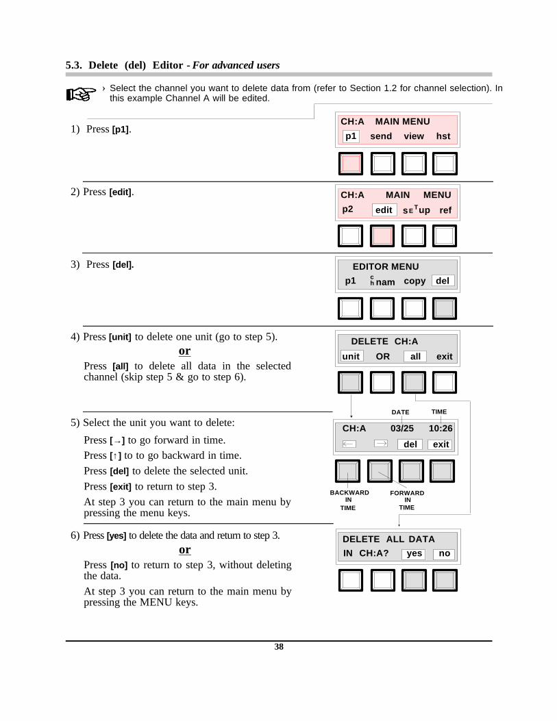
5.3. Delete (del) Editor - For advanced users
› Select the channel you want to delete data from (refer to Section 1.2 for channel selection). Inthis example Channel A will be edited.
1) Press [p1].
2) Press [edit].
3) Press [del].
4) Press [unit] to delete one unit (go to step 5).or
Press [all] to delete all data in the selectedchannel (skip step 5 & go to step 6).
5) Select the unit you want to delete:
Press [→] to go forward in time.Press [↑] to to go backward in time.Press [del] to delete the selected unit.Press [exit] to return to step 3. At step 3 you can return to the main menu bypressing the menu keys.
6) Press [yes] to delete the data and return to step 3.or
Press [no] to return to step 3, without deletingthe data.At step 3 you can return to the main menu bypressing the MENU keys.
CH:A MAIN MENU
send view hstp1
CH:A MAIN MENU
refp2 edit Ts upE
EDITOR MENUdelp1 copynam
ch
DELETE CH:A
unit OR exitall
CH:A 03/25 10:26
del
TIMEDATE
BACKWARDIN
TIME
FORWARDIN
TIME
exit
DELETE DATAALLIN CH:A? yes no
38

5.4. Aim Value (aims) Editor - For advanced users
› Select the channel you want to edit (refer to Section 1.2 for channel selection). In thisexample Channel A and the S.Indx field will be edited.
› Manually editing aim values will delete anyvalues automatically entered.
1) Press [p1].
2) Press [edit].
3) Press [p1].
4) Press [aims].
5) Press [yes] to replace auto aims and continue, orpress [no] to return to step 4.
› This message only appears if references wereautomatically entered using ref.
6) Select field to edit, press [S.Indx].
› Available fields as set by the factory are:S.Indx, C.Indx, B+fog, Dmax, Av.Grd.
Press [edit] after selecting the field name, or[exit] to return to step 4.
7) Enter the aim limit:
Press [↑] to increase the value.Press [↓] to decrease the value.Press [save] to save the aim value and return tostep 6. At step 6 select a different field and enteraim value, or press [exit] to go to step 4, or pressMENU keys to go to main menu.
CH:A MAIN MENU
send view hstp1
CH:A MAIN MENU
refp2 edit Ts upE
EDITOR MENUp2 aims clim eqn
CH:A EDIT AIMSexiteditS.Indx
EDITOR MENU
delp1 copynamch
ENTER S.Indx AIM
AIM 1.38= save
REPLACE AUTO AIMyesW/ MANUAL no
39

5.5. Control Limit (clim) Editor - For advanced users
› Select the channel you want to edit (refer to Section 1.2 for channel selection). In thisexample Channel A and the S.Indx field will be edited. Refer to Appendix A4 for Factory Presets.
1) Press [p1].
2) Press [edit].
3) Press [p1].
4) Press [clim].
5) Select field to edit, press [S.Indx].
› Available fields as set by the factory are:S.Indx, C.Indx, B+fog, Dmax, & Av.Grd.Press [edit] after selecting the field name.
6) Enter the negative control limit:
Press [↑] to increase the value.Press [↓] to decrease the value.Press [next] to continue.
7) Enter the positive control limit:
Press [save] to save clim value and return tostep 5. At step 5 select a different field andenter control limits, or press [exit] to go to step4, or press MENU keys to go to main menu.
CH:A MAIN MENU
send view hstp1
CH:A MAIN MENU
refp2 edit Ts upE
EDITOR MENU
delp1 copynamch
EDITOR MENU
aimsp2 clim eqn
CH:A EDIT C-LIMS
S.Indx edit exit
ENTER S.Indx CLIM
-LIM = - .15 next
ENTER S.Indx CLIM
+LIM = +.15 save
40

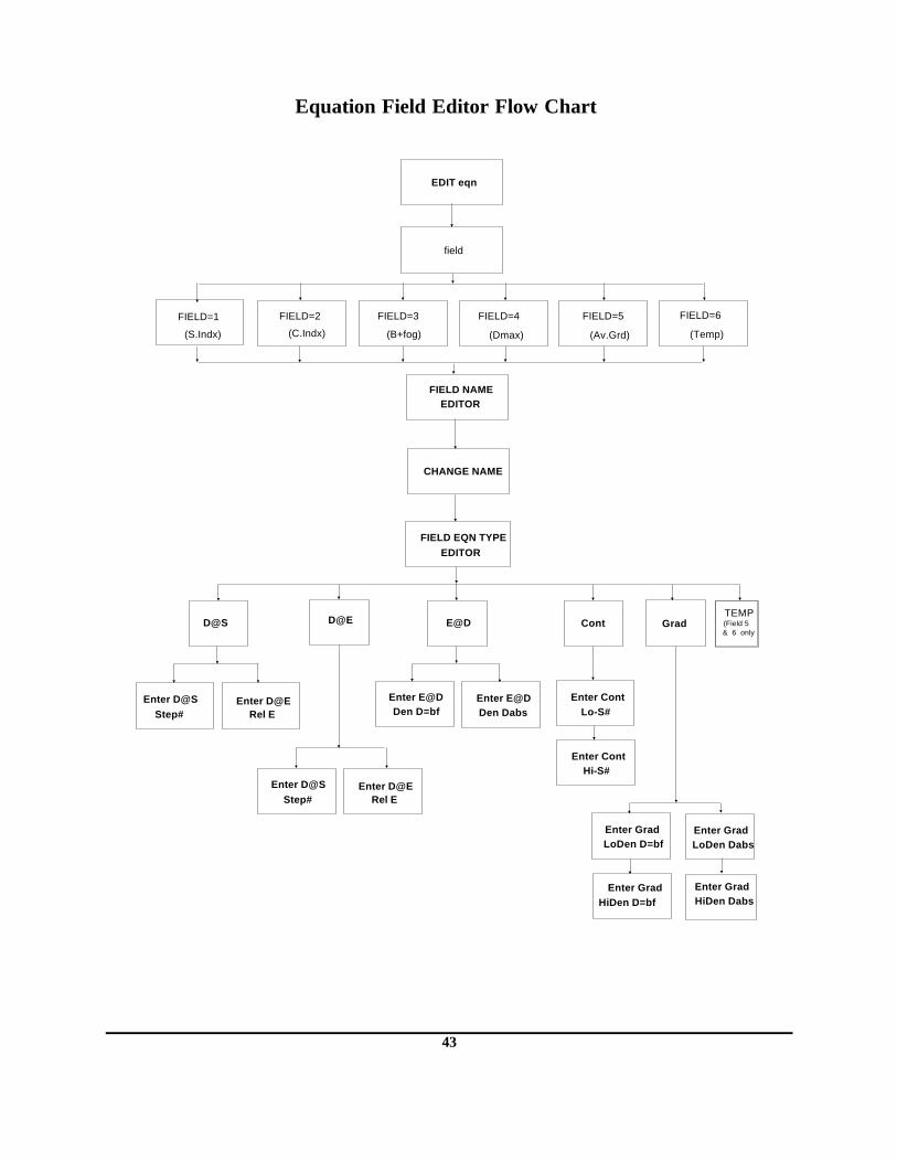
5.6. Equation (eqn) Editor - For advanced users
The Equation Editor (eqn) allows you to define the equations to be displayed in the six userdefinable fields (see Appendix A4 for Factory Presets).
Basic equations types are: • Density @ Step Number (D@S). Where you enter the Step number and the densitometer
computes the Density.• Density @ Exposure Level (D@E). Where you enter the Exposure Level and the
densitometer computes the Density. • Exposure Level @ Density (E@D). Where you enter the Density and the densitometer
computes the Exposure. • Contrast (Cont). Where you enter the Low Step# and High Step# and the densitometer
computes the Contrast. • Gradient (Grad). There are two methods for computing Gradient:
› Using Density = BaseFog + Low & High density (where you enter the Low density and the High densityand the densitometer computes the Gradient.
› Using Density Absolute = Low & High density (where you enter the Low density and the High densityand the densitometer computes the Gradient.
• Temperature (Temp). Sets field to display the temperatures that were manually enteredwith each measurement. Note, temp available for field 5 or 6 only.
You can individually set the six fields to any of the above equation types.
Figures 2 thru 6 graphically represent the five equations.
0.0
1.0
2.0
3.0
4.0
1 2 3 4 5 6 7 8 9 10 11 12 13 14 15 16 17 18 19 20 21
DENSITY
STEP NUMBER
1.54D
S.Indx = 1.54 Av.Grd 2.60B+fog = 0.21Dmax = 3.72C.Indx = 1.75
0.0
1.0
2.0
3.0
4.0
1 2 3 4 5 6 7 8 9 10 11 12 13 14 15 16 17 18 19 20 21
DENSITY
STEP NUMBER.81 LOG REL EXP
.24D
S.Indx = 1.54D( .8E) = 0.24
B+fog = 0.21Dmax = 3.72
Av. Grd 2.60
Fig.2 D&S Fig.3 D@E
Speed index is an example of density at step 11. The densitometer findsstep 11 (D=1.54) and assigns the corresponding density to field one.
To show density at exposure, field 2 was set to calculate density at .81 logrelative exposure. The densitometer finds .81 exposure in the interpolateddensity data set and assigns the associated density value (.24D) to field two.
41

The equation editor has two main sections,field and value editing. If you select field,you can edit the entire field (name, equationtype, and equation data) in one pass. If youselect value, you can only edit the equationdata.
A flowchart of the field and value editfunctions (showing presets) are on thefollowing two pages.
0.0
1.0
2.0
3.0
4.0
1 2 3 4 5 6 7 8 9 10 11 12 13 14 15 16 17 18 19 20 21
DENSITY
STEP NUMBER
BF+1.50=1.71
Speed = 1.71 B+fog = 0.21Dmax = 3.72
Av. Grd. 2.60D( .8E) = 0.21
.210.0
1.0
2.0
3.0
4.0
1 2 3 4 5 6 7 8 9 10 11 12 13 14 15 16 17 18 19 20 21
DENSITY
STEP NUMBER
2.45
2.45 - .70 = 1.75
.70
S.Indx = 1.54 B+fog = 0.21Dmax = 3.72C.Indx = 1.75
Av.Grd 2.60
Fig.4 E@D Fig.5 Contrast
STEP NUMBER
S.Ind = 1.54 B+fog = 0.21Dmax = 3.72C.Indx = 1.75
Av. Grd = 2.60
0.0
1.0
2.0
3.0
4.0
1 2 3 4 5 6 7 8 9 10 11 12 13 14 15 16 17 18 19 20 21
DENSITY
2.21D
.466D
BF+2.00=2.21
BF+.25=.46
Fig.6 Gradient
Speed is an example of exposure at density of base fog + 1.50D. Thedensitometer adds 1.50D to the .21D base fog value, yielding 1.71D. Next, theinterpolated density data searches for a 1.71D match. It finds it at 1.71D logrelative exposure, and assigns the result to field one.
Contrast Index is an example of contrast between step 9 and step 13. Thedensitometer finds step 9 (D=.70) and step 13 (D=2.45), calculates the densitydifference between the steps, and assigns the result (1.75D) to field 2.
Average gradient between base fog plus .25D and base fog plus 2.00D, iscomputed for field 5. The densitomerter finds the densities of 2.21 and .466 in theinterpolated density data set. The corresponding relative exposures are calculated tobe 1.20 & 1.87 log relative exposure. The following equation is solved and it’s resultassigned to field 5:
LOG E EXP. HIGH - LOG E EXP. LOWHIGH DENSITY VALUE - LOW DENSITY VALUE
AV. GRD =
42
TEMP(Field 5
EDIT eqn
field
FIELD=1
(S.Indx)
FIELD NAMEEDITOR
FIELD EQN TYPEEDITOR
CHANGE NAME
D@S D@E E@D Cont Grad
Enter D@S Step#
FIELD=5
(Av.Grd)
FIELD=3
(B+fog)
FIELD=4
(Dmax) (Temp)
FIELD=6FIELD=2
(C.Indx)
Rel EEnter D@E Enter E@D
Den D=bfEnter E@DDen Dabs
Enter ContLo-S#
Enter ContHi-S#
Enter Grad LoDen D=bf
Enter Grad LoDen Dabs
Enter GradHiDen D=bf
Enter GradHiDen Dabs
Enter D@S Step# Rel E
Enter D@E
& 6 only
Equation Field Editor Flow Chart
43

EDIT eqn
Enter D@S Step# Rel E
Enter D@E
Enter ContLo-S#
Enter ContHi-S#
Enter Grad LoDen D=bf
Enter Grad LoDen Dabs
Enter GradHiDen D-bf
Enter GradHiDen Dabs
value
(S.Indx=) (Av.Grd=)(B+fog=) (Dmax=) (Temp F)(C.Indx=)FIELD 1 FIELD 5FIELD 4FIELD 3FIELD 2 FIELD 6
Enter D@S Step# Rel E
Enter D@E
Enter D@S Step# Rel E
Enter D@E
Temp F=
TEMP
Equation Value Editor Flow Chart (Factory Preset)
44

FIELD EDITORThe Field Editor allows you to edit the entire field; name, equation type, and equation data.
› Select the channel you want to edit (refer to Section 1.2 for channel selection). In this exampleChannel A is used. The field name=S.Indx,equation type=D@S, and step=11.
1) Press [p1].
2) Press [edit].
3) Press [p1].
4) Press [eqn].
5) Press [field].
6) Select field to edit, press [S.Indx].
› Available fields as set by the factory are: S.Indx,C.Indx, B+fog, Dmax, Av.Grd, & Temp.
Press [edit] after selecting the field.
7) Enter the field name:
Press [→] to move cursor to next characterPress [↑] to increment thru character list.Press [↓] to decrement thru character list.After entering the channel name, press [save].
CH:A MAIN MENU
send view hstp1
CH:A MAIN MENU
refp2 edit Ts upE
EDITOR MENUdelp1 copynam
ch
EDITOR MENU
aimsp2 clim eqn
CH:AS.Indx= exitedit
FIELD = 1
CH:A _S.Indxsave
CH:A EDIT EQNvaluefield exit
45

Field Editor - continued
8) Select the type of equation, press [D@S].
› Available equations are: Grad (gradient),D@S (Density @ Step), D@E (Density @Exposure), E@D (Exposure @ Density), andCont (Contrast) Refer to the AdditionalNotes at bottom of page.
Press [save] key to continue.
9) Enter the step# for the equation.
Press [↑] to increment.Press [↓] to decrement.Press [save] to save equation data and go to Step5. At step 5 you can edit another equation, orpress [exit] to go to step 4, or press MENU keysto go to main menu.
Additional Notes:› If you select D@S, you can change to D@E computation by pressing [step] at step 9.
› If you select D@E, you can change to D@S computation by pressing [exp] at step 9.
› If you select E@D, you can have density equal to density absolute or density + basefog by pressing[Dabs] or [D=bf] at step 9.
› If you select Cont, you have to enter the Low Step# and the High Step# at step 9.
› If you select Grad, you can have the low and high densities equal to density absolute or density +basefog, by pressing [Dabs] or [D=bf] at step 9.
CH:A EDIT EQNsaveS.Ind = D@S
ENTER D@S STEP#11step = save
46

VALUE EDITORThe Value Editor allows you to edit only the equation data.
› Select the channel you want to edit (refer to Section 1.2 for channel selection). In this exampleChannel A is used. The field name=S.Ind,equation type=D@S, and step=11.
1) Press [p1].
2) Press [edit].
3) Press [p1].
4) Press [eqn].
5) Press [value].
6) Select field to edit, press [S.Indx].› Available fields as set by the factory are: S.Indx,
C.Index, B+fog, Dmax, Av.Grd, & Temp.Press [edit] after selecting the field name.Refer to "Additional Notes" on previous page.
7) Enter the step# for the equation.
Press [↑] to increment.Press [↓] to decrement.Press [save] to save equation data and go to Step5. At step 5 you can edit another equation, or press[exit] to go to step 4, or press MENU keys togo to main menu.
CH:A MAIN MENU
send view hstp1
CH:A MAIN MENU
refp2 edit Ts upE
EDITOR MENUdelp1 copynam
ch
EDITOR MENU
aimsp2 clim eqn
CH:A EDIT EQN
field exitvalue
CH:AS.Indx= edit
EDIT VALUED@S
ENTER D@S STEP#11step = save
47

6. General Maintenance
6.1. Calibration Verification
The 381-25 Calibration Verification Reference is a 21 step film designed to be recognizedby X-Rite Model 381 Auto-Scanning Transmission Densitometers. This instrument featureautomatic calibration and do not require any manual adjustments by the user. The CalibrationVerification Reference provides a method to periodically verify and document theperformance of your scanning densitometer.
Verification Procedure
1. Insert the verification reference through the scanning densitometer in the directionindicated by the arrow at the top of the film. Refer to Section 4.1 for information oninserting films.
2. The density measured by the instrument may beviewed on the instrument display and compared tothe density values printed on the verificationreference to verify the calibration of the instrument.Refer to section 4.2 for information on viewing data.
3. A permanent record of the verification measurementcan be printed to a serial printer. The printout shouldbe dated and the reference density values recordedat the required steps. Refer to section 4.3 forinformation on printing data.
4. The values measured by the instrument should bewithin + /-0.03D or 2% whichever is greater,compared to the values printed on the referencelabel. If this is not the case, ensure that the film is notdirty or damaged and remeasure the film. If the valuesconsistently exceed this limit clean the optics perinstructions in Section 6.2. If the measured values stilldo not fall within the specified limit contact your fieldrepresentative or X-Rite’s Technical ServiceDepartment.
5. It is recommended that the calibration verification procedure be performed once a week.More frequent verification can be performed if required by local regulations.
› Handle the transmission reference at the edges only. Fingerprints or any other foreignsubstance on the measurement area will cause errors. Attempts to dust or clean the surfacewith anything other than a soft camel hair brush may change densities. Minimize change bystoring in a dark, cool, and dry place.
48

Calibration Verification - continued
› This film is intended for use as a verification film for scanning densitometers and should notbe used as a replacement for the transmission reference supplied with other densitometers.
› The calibration scale on X-Rite scanning densitometers built prior to May, 1991 conformed toANSI PH2.19-1976 and should be verified with density values converted to this scale per theinstructions on the outside of the reference’s envelope. Instruments with this calibration scalecan be identified by the silver charger jack on the side of the unit. Current instruments haveblack charger jacks.
6.2. Troubleshooting Chart
Important! Before proceeding with the following troubleshooting chart: - Make sure strip being measured has been properly inserted and is free of smudges,
scratches, and blemishes. Make sure that strips and the unit are free of dust and lint.
Proper antistatic control must be used when replacing the lamp and batteries.
PROBLEM CAUSE SOLUTIONMeasurement densities incorrect. Read lamp weak.* Replace lamp (see Sec. 6.4).
Measurement densities drift. Read lamp weak.* Replace lamp (see Sec. 6.4).
Read lamp not working. Read lamp bad.* Replace lamp (see Sec. 6.4).
Measurement densitiesunrepeatable/incorrect.
Film misaligned. Reinsert strip.
Film has blemishes or scratch. Use different film strip.
< INVALID READING!> isdisplayed after measurement.(Refer to Appendix A3 for moreinvalid reading messages)
Film did not have long enoughleader (1-1/8").
Use film with correct leader.
Exposed region not properlyaligned.
Make sure film feeds straightthrough unit and does not skew.
Use film guide insert (seeSection 2) if film was exposedwith a X-Rite 303, 333, 334, or aCronex sensitometer.
One or more measurementpatches are cloudy, haveexcessive gradients, or haveflecks.
Process and measure a newfilm. Note: A small clear area in a highdensity patch causes large errors. Thiscould be caused by dust specs in thesensitometer during exposure. If so, cleansensitometer and process another film.
Motor drive roller slipping due torestraint or obstruction, orcontamination of rollers fromreading wet strips.
Remove restraint/obstruction ordry drive rollers with air.
Film did not meet requiredexposure criteria.
Adjust sensitometer exposuretime to meet requirements (seeSection 4.1).
Unit will not hold a charge. Nicad batteries are bad. Replace batteries (see Sec. 6.5).
* The instrument has a failure monitor that in most cases will automatically indicate whenthe lamp needs replacement.
49

6.3. Optics Cleaning
To remove any dust and lint from the optics and drive wheel assembly, follow the procedureshown approximately once a week.
1) Holding can in upright postion, insert tube from the canned air into film insertion slot(in front of unit). Make sure the air is clean and free of moisture.
2) With back and forth motion spray air into insertion slot from one end to the other. Dothis several times. This should remove any accumulated dust and lint.
Make sure the air can remains upright.
50

6.4. Read Lamp Replacement P/N 880-07
1) Remove four screws [2] holding bottom cover [3] with a phillips-head screwdriver. Leavebottom cover [3] on unit.
2) Holding top [1] and bottom [2] covers in place, turn unit over so it rests on the bottomcover [3]. Remove top cover [1].
3) Locate optics assembly [4] and remove screw and washer [5] in the middle of lampassembly P.C.B. [6].
4) Lift out old lamp assembly [6] and discard.
5) Install new lamp assembly [6] by carefully inserting lamp [6] into housing [7] and lamppins [8] into lamp connectors. Press down gently to make sure connector pins [8] areproperly seated.
6) Secure lamp screw and washer [5] in place.
7) Carefully clean any dust or plastic chips off circuit board and top cover [1] usingcompressed air. Placetop cover [1] on unit.
8) Holding the top andbottom covers in place,turn unit over so that itrests on the top cover [1].
9) Remove bottom cover[3]. Clean circuit boardand bottom cover [3]with compressed airthen place bottom cover[3] back on instrument.
10) Secure bottom cover [3]to instrument with fourscrews [2] using aphillips-head screwdriver.Make sure that the twolong screws go on theend with the batteryeliminator jack.
11) After lamp is installed,refer to Section 1.3.6 toreset lamp percentagemonitor.
51

6.5. Nicad Battery Replacement (P/N SE15-19 six required)
1) Remove four screws securing the bottom cover with a phillips-head screwdriver.
2) Carefully lift bottom cover upwards and set aside.
3) Lift out nicad battery holder [3] from bottom housing ass’y [4], and remove old batteries.
4) Install new nicad batteries in holder [3] (recognizing proper polarity) and repositionbattery holder [3] back in bottom housing assembly [4].
5) Carefully clean any dust or plastic chips off circuit board [2] and bottom cover usingcompressed air. Place bottom cover on unit.
6) Holding the top [1] and bottom covers in place, turn unit over so that it rests on thebottom cover.
7) Remove top cover [1]. Clean circuit board and top cover [1] with compressed air thenplace top cover back on unit.
8) Turn unit over and secure bottom cover to instrument with four screws using a phillips headscrewdriver. Make sure that the two long screws go on the end with the battery eliminatorjack.
[3]
[1]
[2]
[4]
52

A Appendix
A1. Specifications
Film . . . . . . . . . . . . . . . . . . . . . . . . . . . . . . . . . Measures X-Rite 21- step sensitometer formats exposed on 8" length or longer films.
The exposed sensitometric film must have a sensitometric
exposure with a gamma of .7 or greater on steps 7 thru 15.
There must be a visible density difference between these steps
(density must increase at least .11 D between each step).
Measurement Speed. . . . . . . . . . . . . . . . . . . . 1.2" per second
Spectral Response . . . . . . . . . . . . . . . . . . . . . ANSI Visual
Density Range. . . . . . . . . . . . . . . . . . . . . . . . . 0 - 4.5D
Density Accuracy . . . . . . . . . . . . . . . . . . . . . . ± .02D (0 - 3.00D)(ANSI PH2.19-1986) ± 2.0% (3.01D - 4.00D)
When compared to other densitometers, density variations may exist due to calibration and spectral differences.
Density Repeatability. . . . . . . . . . . . . . . . . . . ± .01D (0 - 3.00D)± 1.0% (3.01 - 3.50D)± 2.0% (3.51 - 4.00D)
Voltage Requirements . . . . . . . . . . . . . . . . . . 120VAC Adaptor P/N SE30-61230VAC Adaptor P/N SE30-62
Dimensions . . . . . . . . . . . . . . . . . . . . . . . . . . . 7.2" x 6.0" x 2.75"182.8mm x 152.4mm x 69.8mm
53

A2. Display Abbreviations
aims - aim valueAv. Grd - Average GradientB+ Fog/bf - Base plus FogCh/ch - ChannelC.Indx - Contrast Index C-Lims - Control Limitscnfg - configurationcont - (in equation setup) a basic contrast equationcpy - copyDabs - Density AbsoluteD@E - Density at Exposuredel - deleteDen - DensityDmax - Density maximumD@S - Density at StepE@D - Exposure at Densityeqn - equationexp - exposuregam - gammagam@D - gamma at densityGrad - (in equation setup) a basic gradient equationHiDen - High DensityHi-S# - High Step Numberhst - historyINFO - informationI/O - Input/OutputLcd - liquid cystal display+ Lim - Upper Control LimitLoDen - Low Density-Lim - Lower Control LimitLo-S# - Low Step Numbernam - namep1 - page 1p2 - page 2p3 - page 3 REF/ref - referenceRel E - Relative ExposureS.Indx - Speed Index
54

A3. Error Messages
ERROR MESSAGE REASON SOLUTIONPress [help] to receive one of thefollwing six invalid readingmessages.
< UNRECOGNIZABLESTRIP>
Film did not have long enoughleader (1 1/8").
Use film with correct leader.
Exposed region not properlyaligned.
Make sure film feeds straightthrough unit and does not skew.Use film guide insert (see Section2) if film was exposed with aX-Rite 303, 333, or 334Sensitometer.
One or more measurementpatches are cloudy, haveexcessive gradients, or haveflecks.
Process and measure a new film.Note: A small clear area in a high densitypatch causes large errors. This could becaused by dust specs in thesensitometer during exposure.If so, cleansensitometer and process another film.
Motor drive roller slipping due torestraint or obstruction, orcontamination of rollers fromreading wet strips.
Remove restraint/obstruction ordry drive rollers with air.
Film did not meet requiredexposure critera.
Adjust sensitometer exposure timeto meet requirements (sec. 4.1)
< EARLY SWITCHRELEASE>
Switch was released beforereading began.
Do not remove strip until afterreading.
< FILM STRIPTOO LONG>
Film strip being measured is toolong.
If excess film exists on either endof exposed area, cut off. Makesure to leave at least 1-1/8" leaderfrom beginning of first region.
< TOO MANYREGIONS>
More than 28 regions onexposure. Mottled exposure areasoften produce many regions.
1) Avoid placing these regions inleader; 2) feed in reversedirection; or 3) cut off mottled end.
< REQUIREDCALIBRATION>
Unit detected zero drift greaterthan ± .01D.
381 automatically recalibratedafter message was displayed.Run strip again.
< A/D HARDWAREFAILURE>
A/D conversion time failure. If occurs repeatedly, service unit.
INVALID READINGhelp
55

Error Messages - continued
ERROR MESSAGE REASON SOLUTION< WARNINGREPLACE LAMP!>
Lamp output is less than requiredintensity. Measurement accuracyof unit is questionable at thispoint.
Replace lamp immediately, seeSection 6.3.
< WARNING!CHARGE BATTERIES>
Indicates that the batteries aregetting low and will soon need tobe charged.
Recharge batteries at aconvenient time.
< PLEASE CONNECTTHE CHARGER>
Indicates that the batteries aretoo low to operate the unit andmust be recharged. This will bedisplayed until you begin therecharge cycle, thereafter, theunit will be functional and allprevious data will be accessible.
Recharge batteries.
< CHECK PRINTER> Incorrect printer selected in setup.Select correct printer, seeSection 1.3.2.
Printer is not connected or offline.
Connect printer or turn printer online.
56

A4. Factory Presets
CHANNEL NAMES
"Xray lab A" - "Xray lab P"
› All sixteen channels (A-P) have the same name with corresponding letters.
FIELD NO. FIELD NAMES EQN TYPE EQN VALUE(S) CLIMS
1 "S. Indx" D@S Step 11 ± .152 "C. Indx" CONT Step 9 & Step 13 ± .153 "B+ Fog" D@S Step 1 ± .034 "Dmax" D@S Step 21 05 "Av. Grd" GRAD .25D+ bf & 2.00D+ bf 06 Temp °F TEMP N/A N/A
› When CLIMS are set to zero no control limits are checked.
HOSPITAL NAME"METROPOLITAN HOSPITAL"
I/O PRESETSPrinter preset is "180si"
baud = 9600 cr = cr/lfpin-5 = cts comp = offformat = new xmit = man.r.c.i. = off width = fulldec. pt = on
57

A5. Accessories
The following printers will interface to the 381 with the cable and DB adaptor supplied.
Diconix Model 150 & 150 Plus Serial Printer
Most Epson Printers with Serial Interface Cards
HP Think Jet Personal Printer
› The HP Think Jet printer may be purchased from X-Rite (P/N 381-113)
Seiko DPU-411 Serial Printer
› Adaptor P/N 881-280 must be purchased to interface the Seiko printer to the 381.
› The Seiko DPU-411 will not plot the process control chart.
X-Rite does carry a variety of "DB" type adaptors and cables to interface your densitometer to acomputer or other serial printers. Ask your X-Rite representative or call X-Rite, Inc. to find out whichadaptor or cable will best meet your requirements.
Diconix is a trademark of Diconix Inc.; Epson is a trademark of Epson Corp.; Seiko is a trademark of Seiko Instruments Inc.; HP is a trademark of Hewlett-Packard Co.
MISCELLANEOUS
380 Series RS232C Interface Manual . . . . . . . . . . . . . . . . . . . . . . . . . . . . . . . . . . . . . . . . . . . . . . . . P/N 380-506
DB Adaptor toPrinter
Interface Cable
381
RS232 Port
58

A6. Serial Printer Configuration
Diconix Model 150 & 150 Plus Serial Printer Setup
Step 1 - Make sure your 381 is set to Diconix printer, refer to Section 1.3.2.
Step 2 - Set serial dip switches on printer, refer to Appendix A9 of printer manual.› Dip switches are located inside the top cover on the left hand side.
150 150 Plus
Dip Switch # Position Description Position Description
1 OFF 9600 Baud OFF 9600 Baud
2 OFF " " OFF " "
3 OFF " " OFF " "
4 ON 8 Bit Word ON 8 Bit Word
5 OFF No Parity OFF No Parity
6 OFF " " OFF " "
7 OFF Hardware Handshake OFF Hardware Handshake
8 OFF " " OFF " "
9 ON Disable Carrier Detect ON Disable Carrier Detect
10 ON Disable Clear To Send OFF Enable Data Set Ready11 OFF Enable Data Set Ready ON Disable Clear To Send
Step 3 - Set mode dip switches on printer, refer to Section 2.6 of printer manual.› Dip switches are located under the top cover on the front side of
the carriage opening.
› All switches are factory set to zero (OFF).
› Set switch five to one (ON) if high quality print is desired.
Diconix Model 180si Serial Printer Setup
Make sure your densitometer is set to 180si printer, refer to Section 1.3.2.
After "180si" is selected, the densitometer will automatically set the printer in the Epson Emulation mode.
Panel B
Panel B
59

Epson Model LX800 & LX810 Printer w/Intelligent Serial Interface # 8148
Step 1 - Make sure your 381 is set to Epson printer, refer to Section 1.3.2.
Step 2 - Set dip switches on the serial interface board. Refer to pages 4 thru 9 in the IntelligentSerial Interface Manual for additional information.
Serial Interface Selection Switch 1
Dip Switch # Position Description
1 OFF 8 Bit Word
2 OFF No Parity
3 OFF " "
4 OFF N/A
5 OFF 9600 Baud
6 ON " "
7 OFF " "
8 OFF " "
Serial Interface Selection Switch 2
Dip Switch # Position Description
1 ON Serial Interface Enable
2 ON Buffer Enable
3 OFF Allow printing when 216
bytes are available in buffer.
4 OFF " "
5 OFF Self test Off
6 OFF " "
Step 3 - Set jumper J8B on the serial interface board to Off (disconnected). This has the effect ofdisabling XON/XOFF flow control. Refer to pages 9 thru 11 in the Intelligent SerialInterface Manual.
Step 4 - Install serial interface card if not installled (refer to Intelligent Serial Interface Manual).
60

Epson Model LX800 & LX810 Printer w/Intelligent Serial Interface # 8148 - continued
Step 5 - Set mode dip switches on the LX800 & LX810 printer. Refer to the Appendix D2 in thePrinter Manual.
› Dip switches are located inside the top cover.
Dip Switch 1
LX800 LX810
Dip Switch # Position Description Position Description
1 OFF 10 cpi OFF 10 cpi2 OFF Unlashed zero OFF Unslashed zero
3 OFF Italic character table OFF Italic character table
4 ON Short tear-off (invalid) ON Short tear-off invalid
5 OFF Draft print speed (high) OFF Print quality = draft
6 ON USA character set ON USA character set
7 ON " " ON " "
8 ON " " ON " "
Dip Switch 2
Dip Switch # Position Description
1 OFF 11 in. page length2 OFF Tractor feed mode
3 OFF No skip over perforation
4 OFF No Auto line feed
61

HP Think Jet Personal Serial Printer Setup
Step 1 - Make sure your 381 is set to Epson printer, refer to Section 1.3.2.
Step 2 - Set Mode dip switches on printer, refer to Appendix A in printer manual.
› Dip switches are located on the back of the printer.
Mode Dip Switch
Dip Switch # Position Description
1 OFF Don’t care (leave as shipped)
2 OFF " "
3 OFF No perf.
4 OFF Page length = 11"
5 ON Epson/IBM mode
6 ON USA character set
7 OFF " "
8 OFF " "
Step 3 - Set RS232 dip switches on printer, refer to Appendix I in printer manual.
RS232 Dip Switch
Dip Switch # Position Description1 ON Handshake = DTR
2 OFF 8 Bit word no parity "
3 OFF " "
4 OFF 9600 baud
5 OFF " "
62

A7. Setup Definition
The setup is contained in three pages: Page 1 (tone, I/O, & time); Page 2 (name & refs);and Page 3 (lamp & °C/F).
PAGE 1• Beeper Loudness (tone) - adjust the beeper loudness (loud, soft, or off). • RS232 parameters (I/O) - sets the parameters of the I/O port.
You can select a preset setting for a specific format output such as: Epson serialprinter, Diconix serial printer, 180si serial printer, Seiko serial printer, 301 Format,Data Interchange Format (for exchanging data with programs such as: DBase, etc.).See chart on next page.You can also select a custom setting, where you individually set the parameters:» Baud Rate - determines the output rate (characters per second) of the I/O port. Available rates are: 300,
600, 1200, 2400, 4800, and 9600.
» Pin5 - determines the status of pin 5 of the I/O port. It can be set to off, busy, or CTS (Clear To Send).Pin 5 should normally be set to off, if it is not going to be used.
» Format - when set to old, the data will be output as: space, density, space, density. When format is setto new, the data will be output as: density, space, density, space.
» R.C.I. - enables or disables Remote Control Interface. RCI allows the ability to remotely control thedensitometer. Refer to the 380 Series RS232C Interface Manual (available from X-Rite, P/N 380-506)for further information on RCI.
» Decimal Point - enables or disables the decimal point during output.
» Carriage Return/line Feed - varies the delimiter at the end of each line. Can be set to carriage returnand line feed or carriage return only.
» Computer - when set to off, the data will be output as: step number, space, equals, space, density, andthen the delimiter (as determined by the carriage return/line feed setting).
Ex. Step# 01 = n.nn < CR> Step # 02 = n.nn < CR>
When comp is set to on, the data will be output as determined by the format setting, and after the laststep, the delimiter (as determined by the carriage return/line feed setting).
Ex. n.nn n.nn n.nn n.nn ... < CR>
» Transmit - enables or disables data from being transmitted automatically after a reading is taken.
» Width - when set to half width, will cause the printer to print the graphics at half the normal width. Whenset to full, the printer will print the graphics at full width.
You can load a preset and then use custom to change the individual settings of theselected preset.
63

Setup Definition - continued
I/O Preset Parameter Chart
I/O PRESET BAUD pin-5 FORMAT r.c.i. dec.pt CR COMP XMIT WIDTH
Epson 9600 CTS NEW OFF ON CRLF OFF MANUAL FULL
Diconix 9600 CTS NEW OFF ON CRLF OFF MANUAL FULL
Seiko 9600 CTS NEW OFF ON CRLF OFF MANUAL HALF
D.I.F. 9600 BUSY NEW ON ON CRLF OFF MANUAL FULL
301 300 CTS OLD OFF OFF CR ON AUTO FULL(Emulation)
180si 9600 CTS NEW OFF ON CRLF OFF MANUAL FULL
• Time/date (time) - sets the time and date of the unit.
PAGE 2
• Name of the unit (name) - enters the name of the unit (ex., Metropolitan Hospital).The name will be printed with the clothesline plot and the characteristic curve plot.
• Reference (ref) - allows you to turn references on or off. If reference is on, thedensitometer will display if the limits were exceeded after each measurement. Also,when you enter view or history you are prompted to select either meas (measured) ordev (as deviated from reference). If reference is off, limit violation is not displayed andyou are not prompted to select either meas or dev in the view or history functions.
PAGE 3
• Lamp counter (lamp) - resets the lamp hours back to zero. This should be done afterreplacing the lamp. You can also check the percent of life remaining for the lamp.
• Temperature Format (°C/F) - allows either celsius or fahrenheit to be displayed andprinted. Temperature format should be selected at initial setup and not changed. Ifthe temperature format is changed after data is stored, all previous temperature datais invalid until the original format is reselected.
64

A8. Proprietary Notice
The information contained in this manual is derived frompatent and proprietary data from X-Rite, Incorporated. Thismanual has been prepared expressly for the purpose of assistingoperation and maintenance personnel in their use and generalmaintenance of the instrument.
Publication of this information does not imply any rights toreproduce or use it for purposes other than installing, operating,or maintaining the equipment described herein.
No part of this manual may be reproduced, transcribed, storedin a retrieval system, or translated into any language or computerlanguage, in any form or by any means: electronic, magnetic,mechanical, optical, manual, or otherwise; without the priorwritten permission of an authorized officer of X-Rite,Incorporated.
THESE PROVISION ARE INTENDED TO STATE ALL OFTHE RIGHTS AND RESPONSIBILITIES BETWEENX-RITE, INCORPORATED AND CUSTOMER. THEYTAKE PLACE OF AND SUPERSEDE ALL WARRANTIES,EXPRESSED OR IMPLIED, AND WHETHER OFMERCHANTABILITY, FITNESS OR OTHERWISE. THEREMEDIES CONTAINED IN THIS OPERATION MANUALARE EXCLUSIVE. CUSTOMER AND X-RITE,INCORPORATED WAIVE ALL OTHER REMEDIES,INCLUDING BUT NOT LIMITED TO CONSEQUENTIALDAMAGES.
This instrument is covered by the following U.S. and foreignpatents: # 4,591,978; 5,062,714; 5,118,183 and other patentspending.
Copyright © 1989 by X-Rite, Incorporated "ALL RIGHTS RESERVED"
65
A9. Warranty
X-Rite, Incorporated warrants each unit manufactured to befree of defects in material and workmanship for a period oftwelve months. THERE ARE NO WARRANTIES OFMERCHANTABILITY OR FITNESS. THIS WARRANTYOBLIGATION IS LIMITED TO SERVICING THE UNITRETURNED TO X-RITE, INCORPORATED FOR THATPURPOSE AND EXCLUDES THE LAMP AND NICADBATTERIES.
The unit shall be returned with transportation charges prepaid.If the fault has been caused by misuse or abnormal conditionsof operations, repairs will be billed at a nominal cost. In this case,an estimate will be submitted before work is started, if requested.
A Warranty Registration Card is enclosed with eachinstrument. The purchaser should fill in the card completely andreturn it to X-Rite, Incorporated postmarked no later than ten(10) days from date of receipt. The card registers your systemwith us for warranty coverage. Once your unit is registered, weare able to maintain a file to help expedite service in case it isneeded. Always include serial number in any correspondenceconcerning the unit. The serial number is located on the bottomof the unit.
X-Rite, Incorporated offers a flat rate repair program forinstruments out of warranty. For more information, refer to yourFlat-Rate Service Policy or contact X-Rite Technical ServicesDepartment.
This agreement shall be interpreted in accordance with the lawsof the State of Michigan and jurisdiction and venue shall lie withthe courts of Michigan as selected by X-Rite, Incorporated.
66