scats adaptive traffic system trb committee a3a18 adaptive traffic control workshop july 1998 note :...
TRANSCRIPT
SCATS Adaptive Traffic SystemTRB Committee A3A18
Adaptive Traffic Control Workshop
July 1998Note : Additional comments available on “Notes” page.
For further information contact: [email protected]
Company: www.tcore.com
2
SCATS - Objectives and Installations• Minimize Stops( light traffic), delay (heavy traffic)
and travel time.
• SCATS is installed in many cities worldwide,
• There are approximately 5000 intersection under SCATS control around the world,
• Largest systems are: Sydney (2000 intersections), Melbourne (2000), Hong Kong (600) and, in the US, Oakland County MI (350).
3
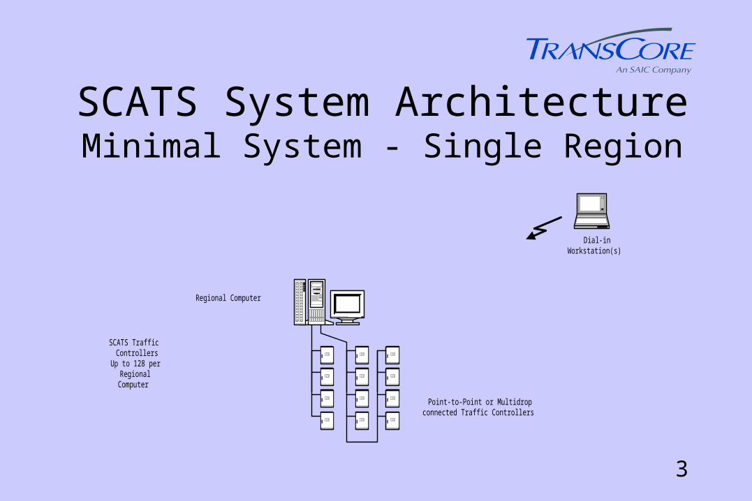
SCATS System ArchitectureMinimal System - Single Region
Regional Computer
SCATS TrafficControllers
Up to 128 perRegionalComputer
Point-to-Point or Multidropconnected Traffic Controllers
Dial-inWorkstation(s)

4
SCATS System ArchitectureExpansion from Single Region
Local RegionalComputers
SCATS TrafficControllers
Up to 128 perRegionalComputer
Point-to-Pointconnected Traffic
Controllers
Multidrop connected Traffic Controllers
Dial-inWorkstation(s)
Data Switch
5
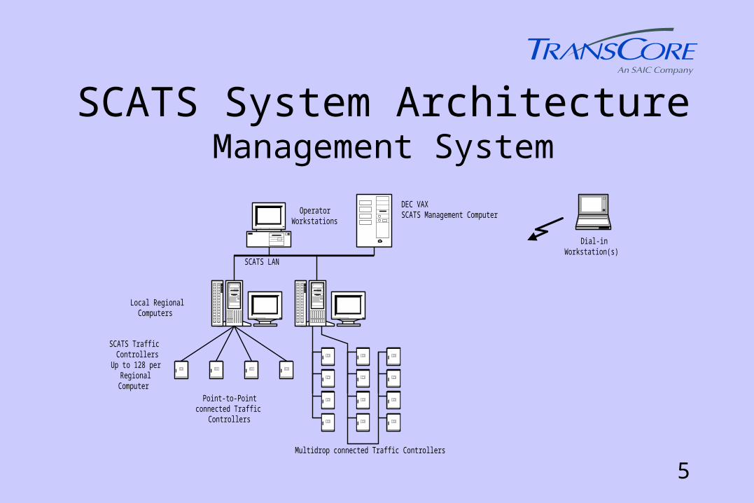
SCATS System ArchitectureManagement System
DEC VAXSCATS Management Computer
SCATS LAN
OperatorWorkstations
Local RegionalComputers
SCATS TrafficControllers
Up to 128 perRegionalComputer
Point-to-Pointconnected Traffic
Controllers
Multidrop connected Traffic Controllers
Dial-inWorkstation(s)
6
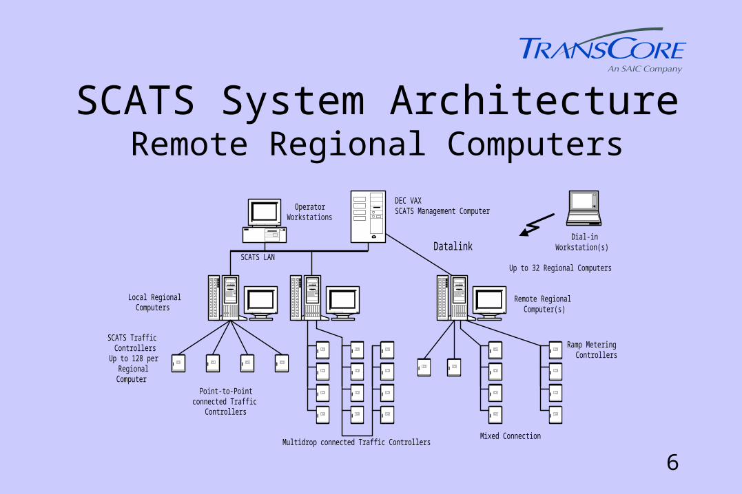
SCATS System ArchitectureRemote Regional Computers
DEC VAXSCATS Management Computer
SCATS LANDatalink
OperatorWorkstations
Ramp MeteringControllers
Up to 32 Regional Computers
Mixed Connection
Remote RegionalComputer(s)
Local RegionalComputers
SCATS TrafficControllers
Up to 128 perRegionalComputer
Point-to-Pointconnected Traffic
Controllers
Multidrop connected Traffic Controllers
Dial-inWorkstation(s)
7
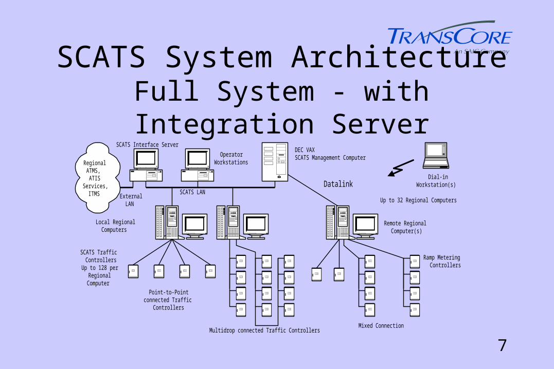
SCATS System ArchitectureFull System - with Integration Server
DEC VAXSCATS Management Computer
SCATS LANDatalink
OperatorWorkstations
SCATS Interface Server
ExternalLAN
Ramp MeteringControllers
Up to 32 Regional Computers
Mixed Connection
Remote RegionalComputer(s)
Local RegionalComputers
SCATS TrafficControllers
Up to 128 perRegionalComputer
Point-to-Pointconnected Traffic
Controllers
Multidrop connected Traffic Controllers
Dial-inWorkstation(s)
RegionalATMS,ATIS
Services,ITMS
8
SCATS System Architecture
• Local Traffic Controllers - tactical control (calling, extension) and data collection,
• Regional Computers - Strategic control,
• Management Computer - Communications and Database functions.
• Simplest configuration - single Regional Computer.
• Operator Interface - Windows 95 or -NT Graphical user interface with point and click access to all parameters.

9
SCATS GUI Example

10
SCATS Data Requirements• Loop Detectors or equivalent (video detection in
Oakland County MI) in each lane at the stop line.
• Detectors used for calling and extension.
• Controller collects number of spaces and total space time during green of each phase, each cycle for use by SCATS adaptive algorithm.
• Actual movement data collected by stop line detectors allows accurate split determination.
11
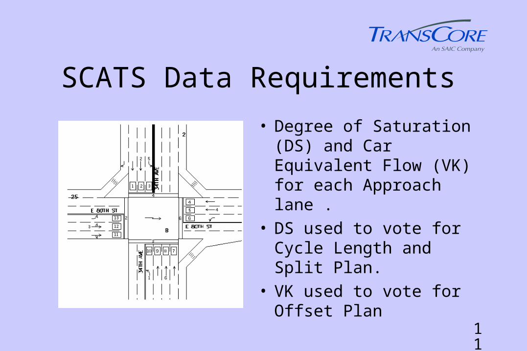
SCATS Data Requirements
• Degree of Saturation (DS) and Car Equivalent Flow (VK) for each Approach lane .
• DS used to vote for Cycle Length and Split Plan.
• VK used to vote for Offset Plan
12
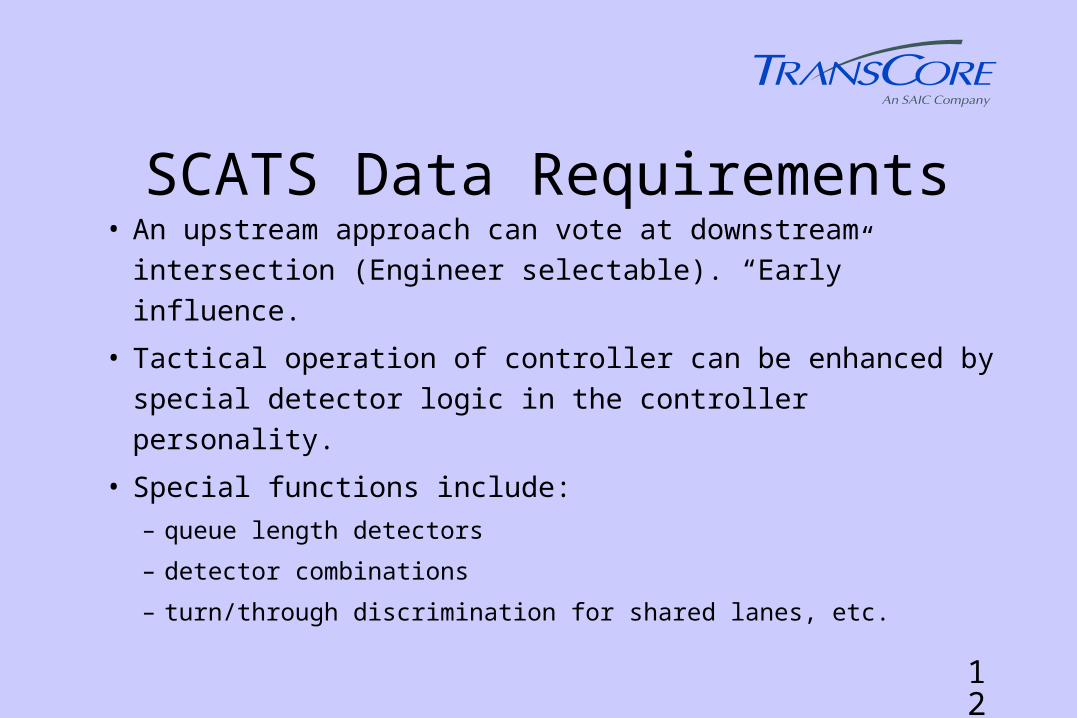
SCATS Data Requirements• An upstream approach can vote at downstream intersection
(Engineer selectable). “Early” influence.
• Tactical operation of controller can be enhanced by special
detector logic in the controller personality.
• Special functions include:
– queue length detectors
– detector combinations
– turn/through discrimination for shared lanes, etc.
13
SCATS Data Requirements
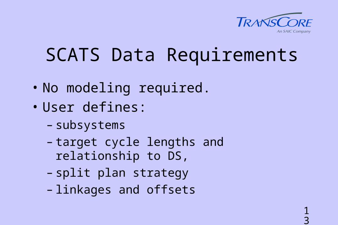
• No modeling required.
• User defines:– subsystems – target cycle lengths and relationship to DS,– split plan strategy– linkages and offsets
14
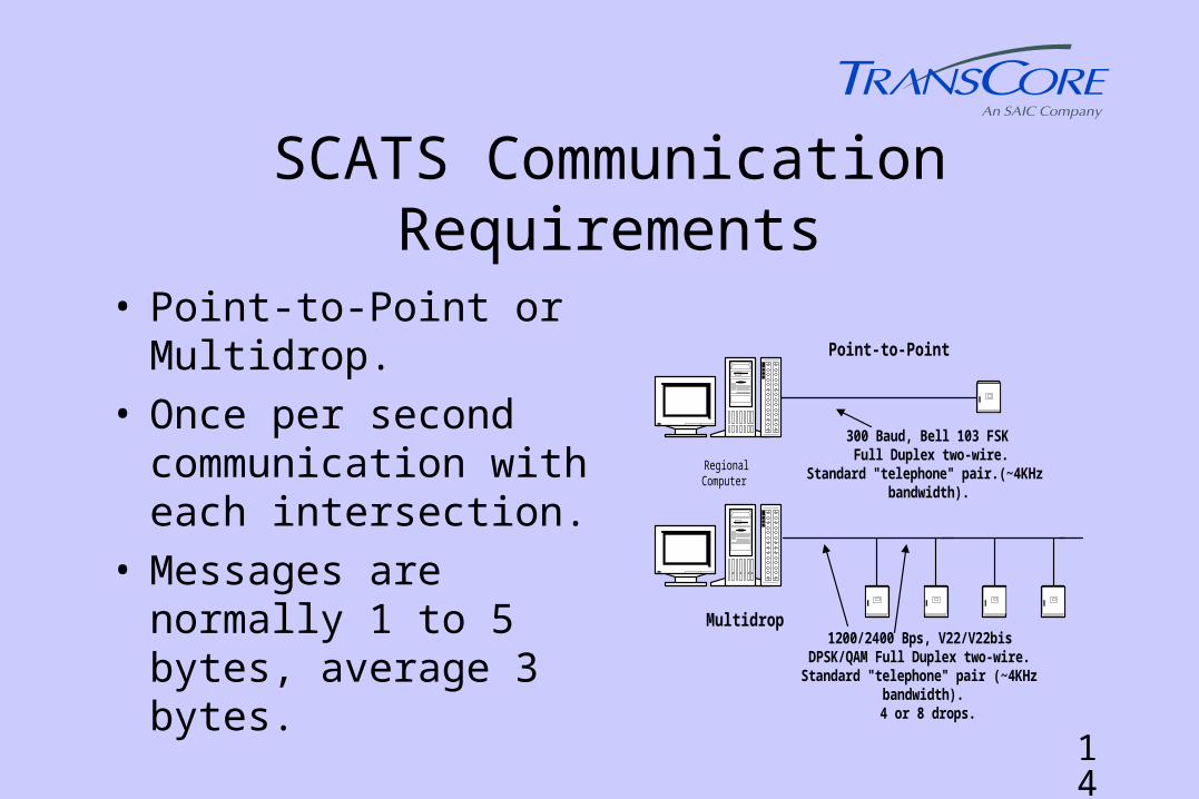
SCATS Communication Requirements
Point-to-Point
300 Baud, Bell 103 FSKFull Duplex two-wire.
Standard "telephone" pair.(~4KHzbandwidth).
1200/2400 Bps, V22/V22bis DPSK/QAM Full Duplex two-wire.Standard "telephone" pair (~4KHz
bandwidth).4 or 8 drops.
Multidrop
RegionalComputer
• Point-to-Point or Multidrop.
• Once per second communication with each intersection.
• Messages are normally 1 to 5 bytes, average 3 bytes.
15
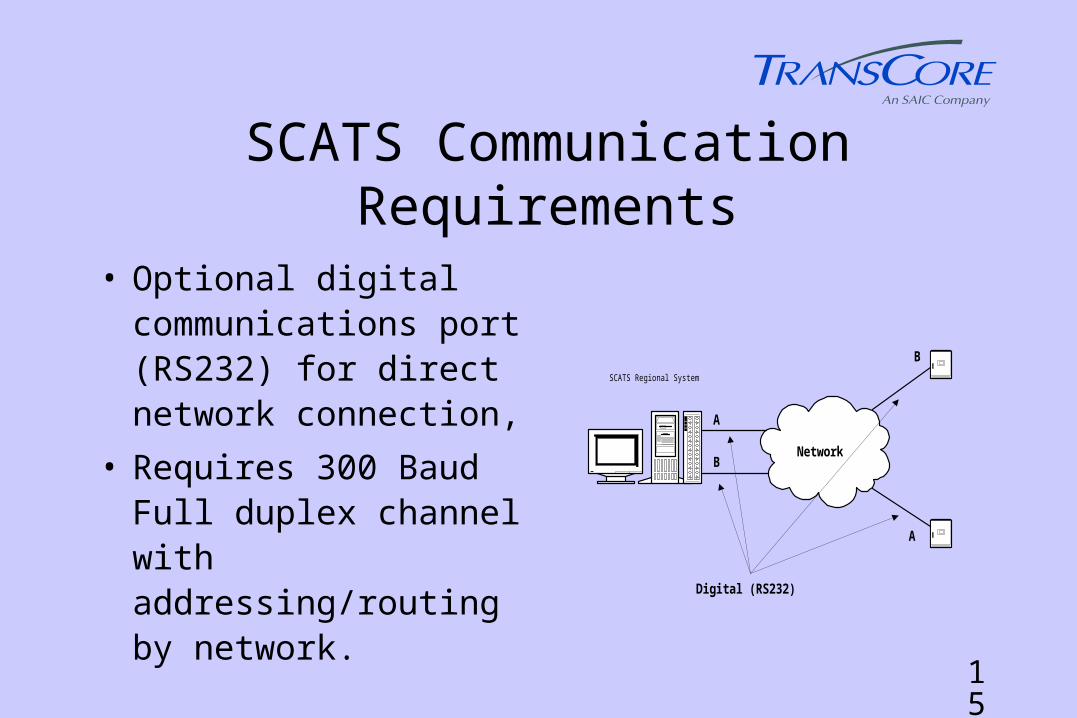
SCATS Communication Requirements
• Optional digital communications port (RS232) for direct network connection,
• Requires 300 Baud Full duplex channel with addressing/routing by network.
Network
A
B
A
B
Digital (RS232)
SCATS Regional System
16
SCATS Hardware Requirements• Management Computer - DEC VAX/ALPHA,
OpenVMS
• Regional Computer - Personal Computer (200 Mhz)
with Windows NT and Digi serial communications
interface modules,
• Local Processor - Traffic Controller with SCATS
functionality, available for NEMA and 170.
17
SCATS Traffic Controllers
• AWA Delta 170 upgrades existing 170 controller to support SCATS.
• Relay Module added for sense/control of cabinet status.
• AWA Delta 3N controller replaces existing NEMA controller.
• Connections are via existing A, B and C connectors.
• One back-panel link required.
170 NEMA
18
SCATS Control Variables• Tactical Control
– presence (locked or non-locked) for phase call– non-occupancy for gapping and wasting (accumulated
waste green) for phase termination.
• Strategic Control– Number of spaces and total space time– Used to develop “Degree of Saturation” DS and Car
“Equivalent Flow” VK
19
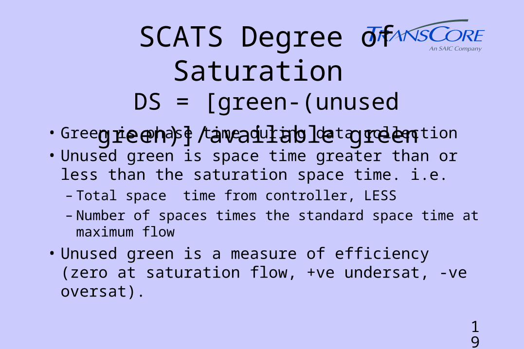
SCATS Degree of Saturation DS = [green-(unused green)]/available green
• Green is phase time during data collection
• Unused green is space time greater than or less than the saturation space time. i.e. – Total space time from controller, LESS – Number of spaces times the standard space time at
maximum flow
• Unused green is a measure of efficiency (zero at saturation flow, +ve undersat, -ve oversat).

20
SCATS Degree of Saturation DS = [green-(unused green)]/available green • Standard space time at maximum flow is self
calibrated daily
• DS is the ratio of efficiently used phase time to available phase time,
• DS can be >100% i.e. during oversaturation the used green can be negative - vehicles are closer than standard space time at maximum flow.
21
SCATS Car Equivalent Flow - VK
• Derived from DS and the lane saturation flow for each lane,
• Independent of vehicle types in traffic stream,
• Allows valid comparisons of competing flows for offset selection.
• VK= DS x green time x vehicles per second at maximum flow
22
SCATS Data Smoothing and Damping • DS and VK are used as weighted averages usually
over three cycles,
• SCATS uses smoothing, damping (i.e.reducing the gain of feedback control loops) and hysteresis extensively,
• It is the calibration of these techniques over years of experience that is the key to effective performance.

23
SCATS DS Usage - Cycle Length
• Delay increases rapidly for CL below Co (optimum CL)
• Exact CL not critical as long as not less than Co
• SCATS Subsystem CL determined from highest value of DS in the subsystem.
Delay
Cycle LengthCo
24
SCATS DS Usage - Cycle Length
• User defined equilibrium DS values used to determine relationship between measured DS and CL.
• Objective to keep CL below user defined targets.
• RL (target CL) determined for measured DS.
• Compared with last CL
• Difference and direction of change RL’

25
SCATS DS Usage - Cycle Length• Weighted average of RL’ (last three cycles) determines
final RL
• CL can move toward final RL by +/- 6 seconds.• CL can change by up to 9 seconds where RL for the last
two cycles was > 6 seconds. (allows response to steep change in demand)
• Subsystems at LCL(low CL) move to SCL (“Stopper” CL) based on flow per cycle parameters, not DS. (i.e. step change).

26
SCATS DS Usage - Split Plan• Possible split plans examined each cycle to
determine the most “equisat” plan for the next cycle, i.e.minimal delay
• Equisat: DS on critical approaches equal,.
• Maximum projected DS for each possible plan calculated (using last cycle DS values). Plan with the lowest maximum selected.
• Projected DS = DS (old split/new split)

27
SCATS DS Usage - Split Plan• For Incremental Split Selection: selection is from 7
possible “plans” for 2 phase (stage) intersection or 37 possible “plans” for 3 and 4 phase (stage) intersections (sample shown below)Plan 21 22 23 24 25Phase 1 -4 2 2 -4 0Phase 2 2 0 2 2 -4Phase 3 0 -4 0 2 2Phase 4 2 2 -4 0 2
(figures are percent change, i.e. plan 21 = 4 % off phase 1, 2 % added to plans 2 and 4.)
28
SCATS Offset Selection• Offset plans are selected by comparing traffic
flows on the links,
• Directional Bias values (DB’s) are entered for each of four plans for each link
• Weighted three-cycle average volumes (VK) are multiplied by the DB’s and the results summed for each plan,
• The plan with the highest sum receives the vote.
29
SCATS Offset Selection• A new offset plan is adopted when 4 of the last 5
votes are for the same plan.
• Two offset values, a and b, are entered for each offset plan, and a CL range, CL1 and CL2, is entered for each plan,
• The offset adopted is a at CL1, b at CL2 and a linear interpolation for CL between CL1 and CL2 (can be disabled if “jump” desired)..
30
SCATS Coordination• Intersections are grouped in Sub-systems,
• A sub-system comprises one or more intersections only one of which is “critical” i.e. requires dynamic split selection,
• All cycle length and split plan voting is carried out at the critical intersection,
• CL and Splits at “minor” intersections in the sub-system are controlled by the critical intersection.
31
SCATS Coordination• All intersections in a sub-system operate at the
same CL and are coordinated via offsets.
• Sub-systems can “marry” to achieve coordination using a separate set of offsets,
• “Married” sub-systems have the same CL,
• “Marriage” and “Divorce” is controlled through voting based on CL and volume and occurs automatically.
32
SCATS Phasing Flexibility• Compatible phases (signal groups or displays)
grouped into STAGES (e.g. main street through may be 2 and 6. These are grouped into Stage A).
• Signal Group control within stages for conditional overlaps, green arrow vs ped. control etc. allowed.
• SCATS has seven Stages, A to G,
• Stages can be introduced in any order,
• Any undemanded stage can be skipped,
33
SCATS Phasing Flexibility• In Isolated and Flexilink (fallback) modes the
sequence is defined in controller “personality”. Several options are provided.
• In Masterlink mode the sequence is determined by data in the Regional Computer.– Split plan features used to control gapping, stage
selection and assignment of unused stage time (e.g. no gap, no gap for % of stage, time gain etc.).

34
SCATS Arterial/Network Capability• Normally arterial, i.e one coordination route,
• Offset plans automatically arranged for low CL, Direction 1, “Business Peak” and Direction 2 use,
• For a network the offset plans can be independent for use on multiple coordination routes. (Select N1 subsystem key option).
• Split plan features can be used to ensure stages run full length to ensure coordination.

35
SCATS Arterial/Network Capability• Offsets between subsystems are defined in the
form LPn=ttppnn i.e. reference offset in this subsystem is offset by tt seconds from the end of Stage pp at intersection nn,
• nn can be different on each of the four offset plans,
• thus coordination decisions are not constrained by simple inbound vs outbound arguments.
36
SCATS Arterial/Network Capability• When SCATS is employed on a grid network,
offsets are selected as dictated for the heavily trafficked routes through the network,
• At all times, as many links as possible will be operating with defined offsets and these will be the links with the greatest flow,
• The remaining links, for which offsets cannot be defined because it would close loops, are those with the lowest traffic flow.

37
SCATS Measures of Effectiveness• MOEs available from system include (per lane):
– SCATS Degree of Saturation DS– VO/VK (actual/calculated vehicles during green)
• MOEs should be measured independently:– SCATS in Sydney is equipped with ANTTS (Automatic
Network Travel Time Subsystem-link travel times from 4000 taxicabs collected and analyzed continuously).
– Unusual Congestion Monitor
38
SCATS Priority Systems - Controller• Five priority inputs provided, one railroad and four
vehicle,
• Vehicle priority inputs accept steady or pulsed signal for different preemption display,
• Preemption display (signal groups), ending overlaps and return stage can be selected,
• Preemption is a function of the controller, SCATS knows preemption is active.
39
SCATS Priority Systems - System
• SCATS Route Preemption Control (RPC) System provides automatic emergency route control from a single input (e.g. fire station pushbutton),
• Route is defined as list of intersections with stage(s) to be held (dwelled), delay from previous I/S and dwell time.
• Monitor is provided for up to 10 intersections.
40
SCATS and Oversaturation• SCATS DS can be >100% i.e. oversaturated,
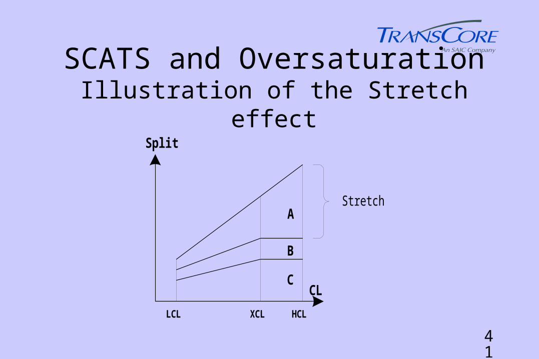
• “Stretch effect” i.e. all stages share extra CL up to XCL after which only the stretch (usually coordination) stage gets the benefit (i.e. a move away from equisat),
• SCATS allows the traffic engineer to decide which route should be favored, by how much and where the queue can be tolerated.
41
SCATS and OversaturationIllustration of the Stretch effect
Split
CL
A
B
C
LCL XCL HCL
Stretch
42
SCATS Controls• SCATS provides many facilities for the traffic
engineer to achieve “custom” control in special circumstances while still maintaining adaptive operation,
• Variation routines at intersections allow special operation based on detection of a parameter value (CL, volumes, stage or phase active, next stage to run etc.) including calling of an operator keystroke “macro”.
43
SCATS Management System
• Inventory System
• Extended Alarm Monitor and log
• Extended System Event log
• Extended System Monitor/Volume Monitor
• Unusual Congestion (Incident) Monitor
• Flow Database System (Count Station Data)
44
SCATS Management System• Flexigen System (auto generation of time based
fallback plans from SCATS data)
• Maintenance Management System
• Vehicle Location System
• Bus Passenger Information System
• “Tidal Flow” Intersection Control System
• VMS Control
End
Thank You