scd4x data sheet - mouser.com
TRANSCRIPT
www.sensirion.com Version 1.1 – April 2021 1/22
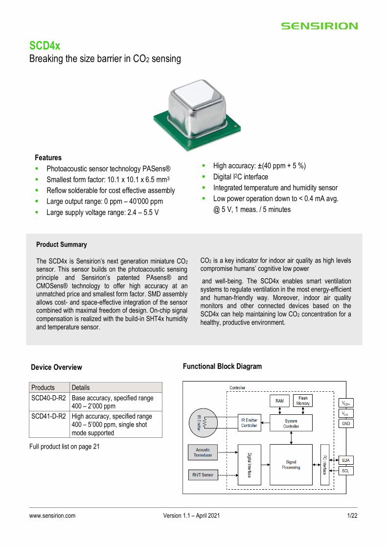
▪ High accuracy: ±(40 ppm + 5 %)
▪ Digital I2C interface
▪ Integrated temperature and humidity sensor
▪ Low power operation down to < 0.4 mA avg.
@ 5 V, 1 meas. / 5 minutes
SCD4x Breaking the size barrier in CO2 sensing
Products Details
SCD40-D-R2 Base accuracy, specified range 400 – 2’000 ppm
SCD41-D-R2 High accuracy, specified range 400 – 5’000 ppm, single shot mode supported
Full product list on page 21
Functional Block Diagram Device Overview
Product Summary
The SCD4x is Sensirion’s next generation miniature CO2 sensor. This sensor builds on the photoacoustic sensing principle and Sensirion’s patented PAsens® and CMOSens® technology to offer high accuracy at an unmatched price and smallest form factor. SMD assembly allows cost- and space-effective integration of the sensor combined with maximal freedom of design. On-chip signal compensation is realized with the build-in SHT4x humidity and temperature sensor.
CO2 is a key indicator for indoor air quality as high levels compromise humans’ cognitive low power
and well-being. The SCD4x enables smart ventilation systems to regulate ventilation in the most energy-efficient and human-friendly way. Moreover, indoor air quality monitors and other connected devices based on the SCD4x can help maintaining low CO2 concentration for a healthy, productive environment.
Features
▪ Photoacoustic sensor technology PASens®
▪ Smallest form factor: 10.1 x 10.1 x 6.5 mm3
▪ Reflow solderable for cost effective assembly
▪ Large output range: 0 ppm – 40’000 ppm
▪ Large supply voltage range: 2.4 – 5.5 V

www.sensirion.com Version 1.1 – April 2021 2/22
Table of Contents 1 Sensor Performance ..................................................................................................................................... 3
1.1 CO2 Sensing Performance ...................................................................................................................... 3
1.2 Humidity Sensing Performance ............................................................................................................... 3 1.3 Temperature Sensing Performance5 ........................................................................................................ 3
2 Specifications ............................................................................................................................................... 4
2.1 Electrical Specifications ........................................................................................................................... 4
2.2 Absolute Maximum Ratings ..................................................................................................................... 4
2.3 Interface Specifications ........................................................................................................................... 5
2.4 Timing Specifications .............................................................................................................................. 6 2.5 Material Contents .................................................................................................................................... 6
3 Digital Interface Description ......................................................................................................................... 7
3.1 Power-Up and Communication Start ........................................................................................................ 7
3.2 Data type & length ................................................................................................................................... 7
3.3 Command Sequence Types .................................................................................................................... 7
3.4 SCD4x Command Overview .................................................................................................................... 8 3.5 Basic Commands .................................................................................................................................... 9
3.6 On-Chip Output Signal Compensation ................................................................................................... 10
3.7 Field Calibration .................................................................................................................................... 12
3.8 Low Power operation............................................................................................................................. 14
3.9 Advanced Features ............................................................................................................................... 15 3.10 Low power single shot (SCD41) ............................................................................................................ 17
3.11 Checksum Calculation ........................................................................................................................... 18
4 Mechanical specifications .......................................................................................................................... 19
4.1 Package Outline .................................................................................................................................... 19
4.2 Land Pattern ......................................................................................................................................... 19
4.3 Tape & Reel Package ........................................................................................................................... 20 4.4 Moisture Sensitivity Level ...................................................................................................................... 20
4.5 Soldering Instructions ............................................................................................................................ 21
4.6 Traceability ........................................................................................................................................... 21
5 Ordering Information .................................................................................................................................. 21
6 Revision History.......................................................................................................................................... 21

www.sensirion.com Version 1.1 – April 2021 3/22
1 Sensor Performance
1.1 CO2 Sensing Performance
Default conditions of 25 °C, 50 % RH, ambient pressure 1013 mbar, default periodic measurement and 3.3 V supply voltage apply to values in the table below, unless otherwise stated.
Parameter Conditions Value
CO2 output range1 - 0 – 40’000 ppm
SCD40 CO2 measurement accuracy2 400 ppm – 2’000 ppm ± (50 ppm + 5% of reading)
SCD41 CO2 measurement accuracy2 400 ppm – 5’000 ppm ± (40 ppm + 5% of reading)
Repeatability Typical ± 10 ppm
Response time3 τ63%, typical 60 s
Accuracy drift per year with automatic self-
calibration algorithm enabled4 Typical ± (5 ppm + 0.5 % of reading)
Table 1: SCD40 and SCD41 CO2 sensor specifications
1.2 Humidity Sensing Performance5
Parameter Conditions Value
Humidity measurement range - 0 %RH – 100 %RH
Accuracy (typ.) 15 °C – 35 °C, 20 %RH – 65 %RH ± 6 % RH
-10 °C – 60 °C, 0 %RH – 100 %RH ± 9 % RH
Repeatability Typical ± 0.4 %RH
Response time3 τ63%, typical 90 s
Accuracy drift - < 0.25 %RH / year
Table 2: SCD4x humidity sensor specifications
1.3 Temperature Sensing Performance5
Parameter Conditions Value
Temperature measurement range - - 10°C – 60°C
Accuracy (typ.) 15 °C – 35 °C ± 0.8 °C
-10 °C – 60 °C ± 1.5 °C
Repeatability - ± 0.1°C
Response time3 τ63%, typical 120 s
Accuracy drift - < 0.03 °C / year
Table 3: SCD4x temperature sensor specifications
1 Exposure to CO2 concentrations smaller than 400 ppm can affect the accuracy of the sensor if the automatic self-calibration (ASC) is on. 2 Deviation to a high-precision reference. Accuracy is fulfilled by > 90% of the sensors after calibration. Rough handling, shipping and soldering reduces the accuracy of the sensor. Accuracy is restored with FRC or ASC recalibration features. Accuracy is based on tests with gas mixtures having a to lerance of ± 1.5%. 3 Time for achieving 63% of a respective step function when operating the SCD41 Evaluation Kit with default measurement mode. Response time depends on design-in, signal update rate and environment of the sensor in the final application. 4 For proper function of ASC field-calibration algorithm SCD4x has to be exposed to air with CO2 concentration 400 ppm regularly. Maximum accuracy drift per year estimated from stress tests is ± (5 ppm + 2 % of reading). Higher drift values may occur if the sensor is not handled according to its handling instructions. 5 Design-in of the SCD4x in final application, self-heating of the sensor and the environment impacts the accuracy of the RH/T sensor. To realize indicated specifications, the temperature-offset of the SCD4x inside the customer device must be set correctly (see chapter 3.6). Best RH/T accuracy is realized when operating the SCD4x in low power periodic measurement mode.

www.sensirion.com Version 1.1 – April 2021 4/22
2 Specifications
2.1 Electrical Specifications
Parameter Symbol Conditions Min. Typical Max. Units
Supply voltage DC VDD 2.4 3.3 or 5.0 5.5 V
Voltage ripple peak to peak VRPP 30 mV
Peak supply current6 VDD = 3.3 V 175 205 mA
VDD = 5 V 115 137 mA
Average supply current for periodic measurement, periodic measurement
IDD VDD = 3.3 V 15 18 mA
VDD = 5 V 11 13 mA
Average supply current for periodic measurement, low power periodic measurement
IDD VDD = 3.3 V 3.2 3.5 mA
VDD = 5 V 2.8 3 mA
Average supply current for periodic single shot
measurement, 1 measurement / 5 minutes (SCD41 only)7
IDD
VDD = 3.3 V 0.45 0.5 mA
VDD = 5 V 0.36 0.4 mA
Input high level voltage VIH 0.7 x VDD 1 x VDD -
Input low level voltage VIL 0.3 x VDD -
Output low level voltage VOL 3 mA sink current 0.66 V
Table 4 SCD4x electrical specifications
2.2 Absolute Maximum Ratings
Stress levels beyond those listed in Table 5 may cause permanent damage to the device. Exposure to minimum/maximum rating conditions for extended periods may affect sensor performance and reliability of the device.
Parameter Conditions Value
Temperature operating conditions -10 – 60°C
Humidity operating conditions8 Non-condensing 0 – 95 %RH
MSL Level 3
DC supply voltage - 0.3 V – 6.0 V
Max voltage on pins SDA, SCL, GND – 0.3 V to VDD+0.3 V
Input current on pins SDA, SCL, GND - 280 mA to 100 mA
Short term storage temperature9 - 40°C – 70°C
Recommended storage temperature 10 °C – 50 °C
ESD HBM 2 kV
ESD CDM 500 V
Maintenance Interval Maintenance free when ASC field-calibration algorithm10 is used.
None
Sensor lifetime11 Typical operating conditions > 10 years
Table 5: SCD4x operation conditions, lifetime and maximum ratings
6 Power supply should be designed with respect to peak current. 7 On-demand measurement with freely adjustable interval. See chapter 3.10 8 Accuracy can be reduced at relative humidity levels lower than 10 %. 9 Short term storage refers to temporary conditions during e.g. transport. 10 For proper function of ASC field-calibration algorithm the SCD4x has to be exposed to clean air with 400 ppm CO2 concentration regularly. 11 Sensor tested over simulated lifetime of > 10 years for indoor environment mission profile

www.sensirion.com Version 1.1 – April 2021 5/22
2.3 Interface Specifications
The SCD4x comes in an LGA package (Table 6). The package outline is schematically displayed in chapter 4.1. The landing pattern of the SCD4x can be found in chapter 4.2.
Name Comments
VDD Supply voltage
VDDH Supply voltage IR source, must be connected to VDD on customer PCB
GND Ground contact
SDA I2C Serial data, bidirectional
SCL I2C Serial clock
DNC
Do not connect, pads must be soldered to a floating pad on
the customer PCB
Table 6 Pin assignment (top view). The notched corner of the protection membrane serves as a
polarity mark to indicate pin 1 location.
VDD and VDDH are used to supply the sensor and must always be kept at the same voltage, i.e. should both be connected to the same power supply. The combined maximum current drawn on VDD and VDDH is indicated in Table 4. Care should be taken to choose a low noise power supply (preferably a low-dropout regulator, LDO, with output ripple of less than 30 mV p-p), which is adequately dimensioned for the relatively large peak currents. Power supply configurations with large transient voltage drops are to be avoided to ensure proper sensor operation. SCL is used to synchronize the I2C communication between the master (microcontroller) and the slave (sensor). The SDA pin is used to transfer data to and from the sensor. For safe communication, the timing specifications defined in the I2C manual12 must be met. Both SCL and SDA lines should be connected to external pull-up resistors (e.g. Rp = 10 kΩ, see Figure 1). To avoid signal contention, the microcontroller must only drive SDA and SCL low. For dimensioning resistor sizes please take bus capacity and communication frequency into account (see example in Section 7.1 of NXPs I2C Manual for more details10). It should be noted that pull-up resistors may be included in I/O circuits of microcontrollers.
Figure 1: Typical application circuit (for better clarity in the image, the positioning of the pins does not reflect the positions on the real sensor). VDD and VDDH must be connected to each other close
to the sensor on the customer PCB.
12 http://www.nxp.com/documents/user_manual/UM10204.pdf

www.sensirion.com Version 1.1 – April 2021 6/22
2.4 Timing Specifications
Table 7 list the timings of the ASIC part and does not reflect the availability or usefulness of the sensor readings. The SCD4x supports the I2C “standard-mode” as is described elsewhere (see footnote 12).
Parameter Condition Min. Max. Unit
Power-up time After hard reset, VDD ≥ 2.25 V - 1000 ms
Soft reset time After re-initialization (i.e. reinit) - 1000 ms
SCL clock frequency - 0 100 kHz
Table 7 System timing specifications.
2.5 Material Contents
The device is fully REACH and RoHS compliant.

www.sensirion.com Version 1.1 – April 2021 7/22
3 Digital Interface Description All SCD4x commands and data are mapped to a 16-bit address space.
SCD4x Hex. Code
I2C address 0x62
Table 8 I2C device address.
3.1 Power-Up and Communication Start
The sensor starts powering-up after reaching the power-up threshold voltage VDD,Min = 2.25 V. After reaching this threshold voltage, the sensor needs 1000 ms to enter the idle state. Once the idle state is entered it is ready to receive commands from the master. Each transmission sequence begins with a START condition (S) and ends with a STOP condition (P) as described in the I2C-bus specification.
3.2 Data type & length
Data sent to and received from the sensor consists of a sequence of 16-bit commands and/or 16-bit words (each to be interpreted as unsigned integer, most significant byte transmitted first). Each data word is immediately succeeded by an 8-bit CRC. In write direction it is mandatory to transmit the checksum. In read direction it is up to the master to decide if it wants to process the checksum (see chapter 3.11).
3.3 Command Sequence Types
The SCD4x features four different I2C command sequence types: “read I2C sequences”, “write I2C sequences”,“send I2C command” and “send command and fetch result” sequences. Figure 2 illustrates how the I2C communication for the different sequence types is built-up.
Figure 2: Command Sequence types: “write” sequence, “send command” sequence, “read”
sequence, and “send command and fetch result” sequence.
For “read”” or “send command and fetch results” sequences, after writing the address and/or data to the sensor and sending the ACK bit, the sensor needs the execution time (see Table 9) to respond to the I2C read header with an ACK bit. Hence, it is required to wait the command execution time before issuing the read header. Commands must not be sent while a previous command is being processed.

www.sensirion.com Version 1.1 – April 2021 8/22
3.4 SCD4x Command Overview
Table 9: List of SCD4x sensor commands. Detailed description of SCD4x commands can be found further down. *Column indicates whether command can be executed while a periodic measurement
is running.
Domain Command Hex. Code
I2C sequence type
(see chapter 3.3)
Execution
time [ms]
During meas.*
Basic Commands
Chapter 3.5
start_periodic_measurement 0x21b1 send command - no
read_measurement 0xec05 read 1 yes
stop_periodic_measurement 0x3f86 send command 500 yes
On-chip output signal compensation
Chapter 3.6
set_temperature_offset 0x241d write 1 no
get_temperature_offset 0x2318 read 1 no
set_sensor_altitude 0x2427 write 1 no
get_sensor_altitude 0x2322 read 1 no
set_ambient_pressure 0xe000 write 1 yes
Field calibration
Chapter 3.7
perform_forced_recalibration 0x362f send command and fetch result
400 no
set_automatic_self_calibration_enabled 0x2416 write 1 no
get_automatic_self_calibration_enabled 0x2313 read 1 no
Low power
Chapter 3.8
start_low_power_periodic_measurement 0x21ac send command - no
get_data_ready_status 0xe4b8 read 1 yes
Advanced features
Chapter 3.9
persist_settings 0x3615 send command 800 no
get_serial_number 0x3682 read 1 no
perform_self_test 0x3639 read 10000 no
perform_factory_reset 0x3632 send command 1200 no
reinit 0x3646 send command 20 no
Low power single shot (SCD41 only) Chapter 3.10
measure_single_shot 0x219d send command 5000 no
measure_single_shot_rht_only 0x2196 send command 50 no

www.sensirion.com Version 1.1 – April 2021 9/22
3.5 Basic Commands
This section lists the basic SCD4x commands that are necessary to start a periodic measurement and subsequently read out the sensor outputs. The typical communication sequence between the I2C master (e.g., a microcontroller) and the SCD4x sensor is as follows:
1. The sensor is powered up 2. The I2C master sends a start_periodic_measurement command. Signal update interval is 5 seconds. 3. The I2C master periodically reads out data with the read measurement sequence. 4. To put the sensor back to idle mode, the I2C master sends a stop periodic measurement command.
While a periodic measurement is running, no other commands must be issued with the exception of read_measurement, get_data_ready_status, stop_periodic_measurement and set_ambient_pressure.
3.5.1 start_periodic_measurement
Description: start periodic measurement, signal update interval is 5 seconds.
Table 10: start_periodic_measurement I2C sequence description
Write (hexadecimal)
Input parameter: - Response parameter: - Max. command duration [ms] length [bytes] signal conversion length [bytes] signal conversion
0x21b1 - - - - not applicable
Example: start periodic measurement
Write 0x21b1
(hexadecimal) Command
3.5.2 read_measurement
Description: read sensor output. The measurement data can only be read out once per signal update interval as the buffer is emptied upon read-out. If no data is available in the buffer, the sensor returns a NACK. To avoid a NACK response, the get_data_ready_status can be issued to check data status (see chapter 3.8.2 for further details). The I2C master can abort the read transfer with a NACK followed by a STOP condition after any data byte if the user is not interested in subsequent data.
Table 11: read_measurment I2C sequence description
Write (hexadecimal)
Input parameter: - Response parameter: CO2, Temperature, Relative Humidity
Max. command duration [ms] length [bytes] signal conversion length [bytes] signal conversion
0xec05 - -
3 CO2 [ppm] = word[0]
1 3 T = - 45 + 175 * word[1] / 216
3 RH = 100 * word[2] / 216
Example: read sensor output (500 ppm, 25 °C, 37 % RH)
Write 0xec05
(hexadecimal) Command
Wait 1 ms command execution time
Response 0x01f4 0x7b 0x6667 0xa2 0x5eb9 0x3c
(hexadecimal) CO2 = 500 ppm CRC of 0x01f4 Temp. = 25 °C CRC of 0x6667 RH = 37 % CRC of 0x5eb9

www.sensirion.com Version 1.1 – April 2021 10/22
3.5.3 stop_periodic_measurement
Description: stop periodic measurement to change the sensor configuration or to save power. Note that the sensor will only respond to other commands after waiting 500 ms after issuing the stop_periodic_measurement command.
Table 12: stop_periodic_measurement I2C sequence description
Write (hexadecimal)
Input parameter: - Response parameter: - Max. command duration [ms] length [bytes] signal conversion length [bytes] signal conversion
0x3f86 - - - - 500
Example: stop periodic measurement
Write 0x3f86
(hexadecimal) Command
3.6 On-Chip Output Signal Compensation
The SCD4x features on-chip signal compensation to counteract pressure and temperature effects. Feeding the SCD4x with the pressure or altitude enables highest accuracy of the CO2 output signal across a large pressure range. Setting the temperature offset improves the accuracy of the relative humidity and temperature output signal. Note that the temperature offset does not impact the accuracy of the CO2 output. To change or read sensor settings, the SCD4x must be in idle mode. A typical sequence between the I2C master and the SCD4x is described as follows:
1. If the sensor is operated in a periodic measurement mode, the I2C master sends a stop_periodic_measurement command.
2. The I2C master sends one or several commands to get or set the sensor settings. 3. If configurations shall be preserved after power-cycle events, the persist_settings command must be sent (see
chapter 3.9.1) 4. The I2C master sends a start measurement command to set the sensor in the operating mode again.
3.6.1 set_temperature_offset
Description: The temperature offset has no influence on the SCD4x CO2 accuracy. Setting the temperature offset of the SCD4x inside the customer device correctly allows the user to leverage the RH and T output signal. Note that the temperature offset can depend on various factors such as the SCD4x measurement mode, self-heating of close components, the ambient temperature and air flow. Thus, the SCD4x temperature offset should be determined inside the customer device under its typical operation conditions (including the operation mode to be used in the application) and in thermal equilibrium. Per default, the temperature offset is set to 4° C. To save the setting to the EEPROM, the persist setting (see chapter 3.9.1) command must be issued. Equation (1) shows how the characteristic temperature offset can be obtained.
𝑇𝑜𝑓𝑓𝑠𝑒𝑡_𝑎𝑐𝑡𝑢𝑎𝑙 = 𝑇𝑆𝐶𝐷40 − 𝑇𝑅𝑒𝑓𝑒𝑟𝑒𝑛𝑐𝑒 + 𝑇𝑜𝑓𝑓𝑠𝑒𝑡_ 𝑝𝑟𝑒𝑣𝑖𝑜𝑢𝑠 (1)
Table 13: set_temperature_offset I2C sequence description
Write (hexadecimal)
Input parameter: Offset temperature Response parameter: - Max. command duration [ms] length [bytes] signal conversion length [bytes] signal conversion
0x241d 3 word[0] = Toffset [°C] * 216 / 175 - - 1
Example: set temperature offset to 5.4 °C
Write 0x241d 0x07e6 0x48
(hexadecimal) Command Toffset = 5.4 °C CRC of 0x7e6

www.sensirion.com Version 1.1 – April 2021 11/22
3.6.2 get_temperature_offset
Table 14: get_temperature_offset I2C sequence description
Write (hexadecimal)
Input parameter: - Response parameter: Offset temperature Max. command duration [ms] length [bytes] signal conversion length [bytes] signal conversion
0x2318 - - 3 Toffset [°C] = 175 * word[0] / 216 1
Example: temperature offset is 6.2 °C
Write 0x2318
(hexadecimal) Command
Wait 1 ms command execution time
Response 0x0912 0x63
(hexadecimal) Toffset = 6.2 °C CRC of 0x0912
3.6.3 set_sensor_altitude
Description: Reading and writing of the sensor altitude must be done while the SCD4x is in idle mode. Typically, the sensor altitude is set once after device installation. To save the setting to the EEPROM, the persist setting (see chapter 3.9.1) command
must be issued. Per default, the sensor altitude is set to 0 meter above sea-level.
Table 15: set_sensor_altitude I2C sequence description
Write (hexadecimal)
Input parameter: Sensor altitude Response parameter: - Max. command duration [ms] length [bytes] signal conversion length [bytes] signal conversion
0x2427 3 word[0] = Sensor altitude [m] - - 1
Example: set sensor altitude to 1’950 m.a.s.l.
Write 0x2427 0x079e 0x09
(hexadecimal) Command Sensor altitude = 1’950 m CRC of 0x79e
3.6.4 get_sensor_altitude
Table 16: get_sensor_altitude I2C sequence description
Write (hexadecimal)
Input parameter: - Response parameter: Sensor altitude Max. command duration [ms] length [bytes] signal conversion length [bytes] signal conversion
0x2322 - - 3 Sensor altitude [m] = word[0] 1
Example: sensor altitude is 1’100 m.a.s.l.
Write 0x2322
(hexadecimal) Command
Wait 1 ms command execution time
Response 0x044c 0x42
(hexadecimal) Sensor altitude = 1’100 m CRC of 0x044c

www.sensirion.com Version 1.1 – April 2021 12/22
3.6.5 set_ambient_pressure
Description: The set_ambient_pressure command can be sent during periodic measurements to enable continuous pressure compensation. Note that setting an ambient pressure using set_ambient_pressure overrides any pressure compensation based on a previously set sensor altitude.
Table 17: set_ambient_pressure I2C sequence description
Write (hexadecimal)
Input parameter: Ambient pressure Response parameter: - Max. command duration [ms] length [bytes] signal conversion length [bytes] signal conversion
0xe000 3 word[0] = ambient P [Pa] / 100
- - 1
Example: set ambient pressure to 98’700 Pa
Write 0xe000 0x03db 0x42
(hexadecimal) Command Ambient P = 98’700 Pa CRC of 0x03db
3.7 Field Calibration
To realize high initial and long-term accuracy, the SCD4x includes two field calibration features. Forced recalibration (FRC) enables restoring highest accuracy with the assistance of a CO2 reference value immediately. Typically, FRC is applied to compensate for drifts originating from the sensor assembly process or other extensive stresses. Automatic self-calibration (ASC) ensures highest long-term stability of the SCD4x without the need of manual action steps from the user. The automatic self-calibration algorithm assumes that the sensor is exposed to the atmospheric CO2 concentration of 400 ppm at least once per week.
3.7.1 perform_forced_recalibration
Description: To successfully conduct an accurate forced recalibration, the following steps need to be carried out: 1. Operate the SCD4x in the operation mode later used in normal sensor operation (periodic measurement, low power
periodic measurement or single shot) for > 3 minutes in an environment with homogenous and constant CO2 concentration.
2. Issue stop_periodic_measurement. Wait 500 ms for the stop command to complete. 3. Subsequently issue the perform_forced_recalibration command and optionally read out the FRC correction (i.e. the
magnitude of the correction) after waiting for 400 ms for the command to complete.
• A return value of 0xffff indicates that the forced recalibration has failed. Note that the sensor will fail to perform a forced recalibration if it was not operated before sending the command. Please make sure that the sensor is operated at the voltage desired for the application when applying the forced recalibration sequence.
www.sensirion.com Version 1.1 – April 2021 13/22
Table 18: perform_forced_recalibration I2C sequence description
Write (hexadecimal)
Input parameter: Target CO2 concentration Response parameter: FRC-correction Max. command duration [ms] length [bytes] signal conversion length [bytes] signal conversion
0x362f 3 word[0] = Target concentration [ppm CO2]
3 FRC correction [ppm CO2] = word[0] – 0x8000
word[0] = 0xffff in case of
failed FRC
400
Example: perform forced recalibration, reference CO2 concentration is 490 ppm
Write 0x362f 0x01e0 0xb4
(hexadecimal) Command Input: 480 ppm CRC of 0x01e0
Wait 400 ms command execution time
Response 0x7fce 0x7b
(hexadecimal) Response: - 50 ppm CRC of 0x7fce
3.7.2 set_automatic_self_calibration_enabled
Description: Set the current state (enabled / disabled) of the automatic self-calibration. By default, ASC is enabled. To save the setting to the EEPROM, the persist_setting (see chapter 3.9.1) command must be issued.
Table 19: set_automatic_self_calibration_enabled I2C sequence description.
Write (hexadecimal)
Input parameter: ASC enabled Response parameter: - Max. command duration [ms] length [bytes] signal conversion length [bytes] signal conversion
0x2416 3 word[0] = 1 → ASC enabled
word[0] = 0 → ASC disabled
- - 1
Example: set automatic self-calibration status: enabled
Write 0x2416 0x0001 0xB0
(hexadecimal) Command ASC enabled CRC of 0x0001
3.7.3 get_automatic_self_calibration_enabled
Table 20: get_automatic_self_calibration_enabled I2C sequence description
Write (hexadecimal)
Input parameter: - Response parameter: ASC enabled Max. command duration [ms] length [bytes] signal conversion length [bytes] signal conversion
0x2313 - - 3 word[0] = 1 → ASC enabled
word[0] = 0 → ASC disabled
1
Example: read automatic self-calibration status: disabled
Write 0x2313
(hexadecimal) Command
Wait 1 ms command execution time
Response 0x0000 0x81
(hexadecimal) ASC disabled CRC of 0x0000

www.sensirion.com Version 1.1 – April 2021 14/22
3.8 Low Power operation
To enable use-cases with a constrained power-budget, the SCD4x features a low power periodic measurement mode with signal update interval of approximately 30 seconds. While the low power mode saves power and reduces self-heating of the sensor, the low power periodic measurement mode has a longer response time. The low power periodic measurement mode is initiated and read-out in a similar manner as the default periodic measurement. Please consult chapter 3.5.2 for further instructions. To avoid receiving a NACK in case the result of a subsequent measurement is not ready yet, the get_data_ready_status command can be used to check whether new measurement data is available for read-out.
3.8.1 start_low_power_periodic_measurement
Description: start low power periodic measurement, signal update interval is approximately 30 seconds.
Table 21: start_low_power_periodic_measurement I2C sequence description
Write (hexadecimal)
Input parameter: - Response parameter: - Max. command duration [ms] length [bytes] signal conversion length [bytes] signal conversion
0x21ac - - - - not applicable
Example: start low power periodic measurement
Write 0x21ac
(hexadecimal) Command
3.8.2 get_data_ready_status
Table 22: get_data_ready_status I2C sequence description
Write (hexadecimal)
Input parameter: - Response parameter: data ready status Max. command duration [ms] length [bytes] signal conversion
length [bytes]
signal conversion
0xe4b8 - - 3 If the least significant 11 bits of word[0] are 0 → data not ready
else → data ready for read-out
1
Example: read data ready status: data not ready
Write 0xe4b8
(hexadecimal) Command
Wait 1 ms command execution time
Response 0x8000 0xa2
(hexadecimal) Least significant 11 bits are 0 → data not ready CRC of 0x8000

www.sensirion.com Version 1.1 – April 2021 15/22
3.9 Advanced Features
3.9.1 persist_settings
Description: Configuration settings such as the temperature offset, sensor altitude and the ASC enabled/disabled parameter are by default stored in the volatile memory (RAM) only and will be lost after a power-cycle. The persist_settings command stores the current configuration in the EEPROM of the SCD4x, making them persistent across power-cycling. To avoid unnecessary wear of the EEPROM, the persist_settings command should only be sent when persistence is required and if actual changes to the configuration have been made. The EEPROM is guaranteed to endure at least 2000 write cycles before failure. Note that field calibration history (i.e. FRC and ASC, see chapter 3.7) is automatically stored in a separate EEPROM dimensioned for the specified sensor lifetime.
Table 23: persist_settings I2C sequence description
Write (hexadecimal)
Input parameter: - Response parameter: - Max. command duration [ms] length [bytes] signal conversion length [bytes] signal conversion
0x3615 - - - - 800
Example: persist settings
Write 0x3615
(hexadecimal) Command
3.9.2 get_serial_number
Description: Reading out the serial number can be used to identify the chip and to verify the presence of the sensor. The get serial number command returns 3 words, and every word is followed by an 8-bit CRC checksum. Together, the 3 words constitute a unique serial number with a length of 48 bits (big endian format).
Table 24: get_serial_number I2C sequence description
Write (hexadecimal)
Input parameter: - Response parameter: serial number Max. command duration [ms] length [bytes] signal conversion length [bytes] signal conversion
0x3682 - - 9 Serial number = word[0] << 32 | word[1] << 16 | word[2]
1
Example: serial number is 273’325’796’834’238
Write 0x3682
(hexadecimal) Command
Wait 1 ms command execution time
Response 0xf896 0x31 0x9f07 0xc2 0x3bbe 0x89
(hexadecimal) word[0] CRC of 0xf896 word[1] CRC of 0x9f07 word[2] CRC of 0x3bbe

www.sensirion.com Version 1.1 – April 2021 16/22
3.9.3 perform_self_test
Description: The perform_self_test feature can be used as an end-of-line test to check sensor functionality and the customer power supply to the sensor.
Table 25: perform_self_test I2C sequence description
Write (hexadecimal)
Input parameter: - Response parameter: sensor status Max. command duration [ms] length [bytes] signal conversion length [bytes] signal conversion
0x3639 - - 3 word[0] = 0 → no malfunction detected
word[0] ≠ 0 → malfunction detected
10000
Example: perform self-test, no malfunction detected
Write 0x3639
(hexadecimal) Command
Wait 10000 ms command execution time
Response 0x0000 0x81
(hexadecimal) No malfunction detected CRC of 0x0000
3.9.4 perfom_factory_reset
Description: The perform_factory_reset command resets all configuration settings stored in the EEPROM and erases the FRC and ASC algorithm history.
Table 26: perform_factory_reset I2C sequence description
Write (hexadecimal)
Input parameter: - Response parameter: - Max. command duration [ms] length [bytes] signal conversion length [bytes] signal conversion
0x3632 - - - - 1200
Example: perform factory reset
Write 0x3632
(hexadecimal) Command
3.9.5 reinit
Description: The reinit command reinitializes the sensor by reloading user settings from EEPROM. Before sending the reinit command, the stop measurement command must be issued. If the reinit command does not trigger the desired re-initialization, a power-cycle should be applied to the SCD4x.
Table 27: reinit I2C sequence description
Write (hexadecimal)
Input parameter: - Response parameter: - Max. command duration [ms] length [bytes] signal conversion length [bytes] signal conversion
0x3646 - - - - 20
Example: reinit
Write 0x3646
(hexadecimal) Command re-initialization

www.sensirion.com Version 1.1 – April 2021 17/22
3.10 Low power single shot (SCD41)
In addition to periodic measurement modes, the SCD41 features a single shot measurement mode, i.e. allows for on-demand measurements. The typical communication sequence is as follows:
1. The sensor is powered up. 2. The I2C master sends a single shot command and waits for the indicated max. command duration time. 3. The I2C master reads out data with the read measurement sequence (chapter 3.5.2). 4. Steps 2-3 are repeated as required by the application.
To reduce noise levels, the I2C master can perform several single shot measurements in a row and average the CO2 output values. After a power cycle, the initial two single shot readings should be discarded to maximize accuracy. The idle current in between measurements is 0.15 mA (typ.), respectively 0.2 mA (max.). The energy consumed per single shot typically is 243 mJ (296 mJ max.). As for the periodic measurement modes, the automatic self-calibration (ASC) is enabled per default in single shot operation. The automatic self-calibration is optimized for single shot measurements performed every 5 minutes. Longer measurement intervals will result in less frequent self-calibration sequences. Note that no self-calibration is issued if the sensor is power-cycled between single shot measurements Please consult Chapter 3.7 for a detailed description of the automatic-self calibration and the corresponding commands.
3.10.1 measure_single_shot
Description: On-demand measurement of CO2 concentration, relative humidity and temperature. The sensor output is read using the read_measurement command (chapter 3.5.2).
Table 28: measure_single_shot I2C sequence description
Write (hexadecimal)
Input parameter: - Response parameter: - Max. command duration [ms] length [bytes] signal conversion length [bytes] signal conversion
0x219d - - - - 5000
Example: measure single shot
Write 0x219d
(hexadecimal) Command
3.10.2 measure_single_shot_rht_only
Description: On-demand measurement of relative humidity and temperature only. The sensor output is read using the read_measurement command (chapter 3.5.2). CO2 output is returned as 0 ppm.
Table 29: measure_single_shot_rht_only I2C sequence description
Write (hexadecimal)
Input parameter: - Response parameter: - Max. command duration [ms] length [bytes] signal conversion length [bytes] signal conversion
0x2196 - - - - 50
Example: measure single shot, RH and T output only
Write 0x2196
(hexadecimal) Command
www.sensirion.com Version 1.1 – April 2021 18/22
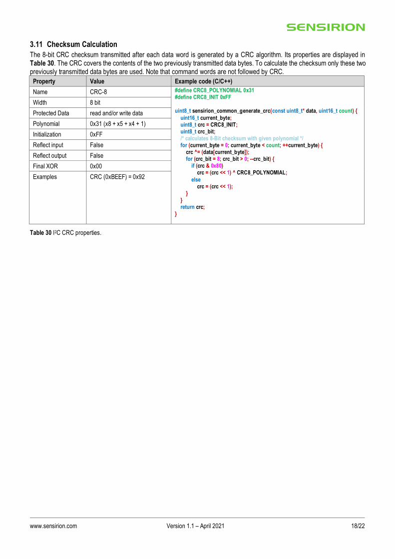
3.11 Checksum Calculation
The 8-bit CRC checksum transmitted after each data word is generated by a CRC algorithm. Its properties are displayed in Table 30. The CRC covers the contents of the two previously transmitted data bytes. To calculate the checksum only these two previously transmitted data bytes are used. Note that command words are not followed by CRC.
Property Value Example code (C/C++)
Name CRC-8 #define CRC8_POLYNOMIAL 0x31 #define CRC8_INIT 0xFF uint8_t sensirion_common_generate_crc(const uint8_t* data, uint16_t count) {
uint16_t current_byte; uint8_t crc = CRC8_INIT; uint8_t crc_bit; /* calculates 8-Bit checksum with given polynomial */ for (current_byte = 0; current_byte < count; ++current_byte) { crc ^= (data[current_byte]); for (crc_bit = 8; crc_bit > 0; --crc_bit) { if (crc & 0x80) crc = (crc << 1) ^ CRC8_POLYNOMIAL;
else crc = (crc << 1); } } return crc; }
Width 8 bit
Protected Data read and/or write data
Polynomial 0x31 (x8 + x5 + x4 + 1)
Initialization 0xFF
Reflect input False
Reflect output False
Final XOR 0x00
Examples CRC (0xBEEF) = 0x92
Table 30 I2C CRC properties.
www.sensirion.com Version 1.1 – April 2021 19/22
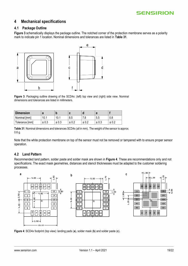
4 Mechanical specifications
4.1 Package Outline
Figure 3 schematically displays the package outline. The notched corner of the protection membrane serves as a polarity mark to indicate pin 1 location. Nominal dimensions and tolerances are listed in Table 31.
Figure 3: Packaging outline drawing of the SCD4x: (left) top view and (right) side view. Nominal
dimensions and tolerances are listed in millimeters.
Dimension a b c d e f
Nominal [mm] 10.1 10.1 8.5 7.8 5.5 0.8
Tolerance [mm] ± 0.3 ± 0.3 ± 0.2 ± 0.2 ± 0.3 ± 0.2
Table 31: Nominal dimensions and tolerances SCD4x (all in mm). The weight of the sensor is approx.
0.6 g.
Note that the white protection membrane on top of the sensor must not be removed or tampered with to ensure proper sensor operation.
4.2 Land Pattern
Recommended land pattern, solder paste and solder mask are shown in Figure 4. These are recommendations only and not specifications. The exact mask geometries, distances and stencil thicknesses must be adapted to the customer soldering processes.
Figure 4: SCD4x footprint (top view): landing pads (a), solder mask (b) and solder paste (c).

www.sensirion.com Version 1.1 – April 2021 20/22
4.3 Tape & Reel Package
Figure 5: Technical drawing of the packaging tape with sensor orientation in tape. Header tape is to
the right and trailer tape to the left on this drawing. Dimensions are given in millimeters.
4.4 Moisture Sensitivity Level
Sensirion SCD4x sensors shall be treated according to Moisture Sensitivity Level 3 (MSL3) as described in IPC/JEDEC J-STD-033B1. Exposure to moisture levels or solder reflow temperatures, which exceed the limits as stated in this document, can result in yield loss and reliability degradation. The manufacturing floor time (out of bag) at the customer’s end is 168 hours at normal factory conditions (≤30°C and 60%RH). If sensors are not mounted within this time, or have been exposed to higher temperatures and humidity (>30°C and >60%RH), or there is any doubt about the airtight integrity of the dry pack, the parts should be baked (baking parameters see Table 32). The maximum allowed baking temperature is 40°C if the sensors are inside the reel.
Table 32: Baking condition SCD4x if floor time (168 h) with open bag is exceeded.
SCD4x package type Baking temperature Min. baking time Baking condition
Sensors removed from tape 90 °C 48 hours RH < 5 %
Sensors in tape 40 °C 23 days RH < 5 %

www.sensirion.com Version 1.1 – April 2021 21/22
4.5 Soldering Instructions
For soldering, standard reflow soldering ovens may be used. The sensors are designed to withstand soldering profile according to IPC/JEDEC J-STD-020 with a maximum peak temperature of 235°C during up to 30 sec for Pb-free assembly in IR/Convection reflow ovens. Note that due to the comparably large size of the SCD4x sensor significant temperature differences across the sensor element can occur during reflow soldering. Specifically, the temperature within the sensor cap can be higher than the temperature measured at the pad using usual temperature monitoring methods. Care must be taken that a temperature of 235° C is not exceeded at any time in any part of the sensor. Do not apply any board wash process step subsequently to the reflow soldering. Note that the dust cover on top of the cap must not be removed or wetted with any liquid. Finally, the SCD4x is not compatible with vapor phase reflow soldering.
Average ramp-up rate < 3 °C / second
Liquid phase
▪ TL
▪ tL
< 220 °C < 60 seconds
Peak temperature
▪ TP ▪ tP
≤ 235 °C < 30 seconds
Ramp-down rate < 4 °C / seconds for temperature > TL
Table 33 Soldering profile parameter
4.6 Traceability
All SCD4x sensors have a distinct electronic serial number for identification and traceability (see chapter 3.9.2). The serial number can be decoded by Sensirion only and allows for tracking through production, calibration, and testing.
5 Ordering Information Use the part names and product numbers shown in the following table when ordering the SCD4x CO2 sensor. For the latest product information and local distributors, visit http://www.sensirion.com/.
Part Name Description Ordering quantity (pcs) Product Number
SCD40-D-R2 SCD40 CO2 sensor SMD component as reel, I2C 600 sensors per reel 3.000.521
SCD40-D-R1 SCD40 CO2 sensor SMD component as reel, I2C 60 sensors per reel 3.000.496
SCD41-D-R2 SCD41 CO2 sensor SMD component as reel, I2C 600 sensors per reel 3.000.498
SCD41-D-R1 SCD41 CO2 sensor SMD component as reel, I2C 60 sensors per reel 3.000.497
SEK-SCD41-Sensor SEK-SCD41-Sensor set; SCD41 on development board with cables
1 3.000.455
SEK-SensorBridge Sensor Bridge to connect SEK-SCD41-Sensor to computer
1 3.000.124
Table 34 SCD4x ordering options
6 Revision History
Date Version Page(s) Changes
January 2021 1 all Initial release
April 2021 1.1 16 - 17 Adjustment max. command time self-test (chapter 3.9) and single shot (chapter 3.10), minor revisions on other pages

www.sensirion.com Version 1.1 – April 2021 22/22
Important Notices Warning, Personal InjuryDo not use this product as safety or emergency stop devices or in any other application where failure of the product could result in personal injury. Do not use this product for applications other than its intended and authorized use. Before installing, hand ling, using or servicing this product, please consult the data sheet and application notes. Failure to comply with these instructions could result in death or serious injury. If the Buyer shall purchase or use SENSIRION products for any unintended or unauthorized application, Buyer shall defend, indemnify and hold
harmless SENSIRION and its officers, employees, subsidiaries, affiliates and distributors against all claims, costs, damages and expenses, and reasonable attorney fees arising out of, directly or indirectly, any claim of personal injury or death associated with such unintended or unauthorized use, even if SENSIRION shall be allegedly negligent with respect to the design or the manufacture of the product.
ESD Precautions
The inherent design of this component causes it to be sensitive to electrostatic discharge (ESD). To prevent ESD-induced damage and/or
degradation, take customary and statutory ESD precautions when handling this product.
Warranty
SENSIRION warrants solely to the original purchaser of this product for a period of 12 months (one year) from the date of delivery that this product shall be of the quality, material and workmanship defined in SENSIRION’s published specifications of the product. Within such period, if proven to be defective, SENSIRION shall repair and/or replace this product, in SENSIRION’s discretion, free of charge to the Buyer, provided that:
• notice in writing describing the defects shall be given to SENSIRION within fourteen (14) days after their appearance;
• such defects shall be found, to SENSIRION’s reasonable satisfaction, to have arisen from SENSIRION’s faulty design, material, or workmanship;
• the defective product shall be returned to SENSIRION’s factory at the Buyer’s expense; and
• the warranty period for any repaired or replaced product shall be limited to the unexpired portion of the original period. This warranty does not apply to any equipment which has not been installed and used within the specifications recommended by SENSIRION for the intended and proper use of the equipment. EXCEPT FOR THE WARRANTIES EXPRESSLY SET FORTH HEREIN, SENSIRION MAKES NO WARRANTIES, EITHER EXPRESS OR IMPLIED, WITH RESPECT TO THE PRODUCT. ANY AND ALL WARRANTIES, INCLUDING WITHOUT LIMITATION, WARRANTIES OF MERCHANTABILITY OR FITNESS FOR A PARTICULAR PURPOSE, ARE EXPRESSLY EXCLUDED AND
DECLINED. SENSIRION is only liable for defects of this product arising under the conditions of operation provided for in the data sheet and proper use of the goods. SENSIRION explicitly disclaims all warranties, express or implied, for any period during which the goods are operated or stored not in accordance with the technical specifications. SENSIRION does not assume any liability arising out of any application or use of any product or circuit and specifically disc laims any and all liability, including without limitation consequential or incidental damages. All operating parameters, including without limitation recommended parameters, must be validated for each customer’s applications by customer’s technical experts. Recommended parameters can an d do vary in different applications. SENSIRION reserves the right, without further notice, (i) to change the product specifications and/or the information in this document and (ii) to
improve reliability, functions and design of this product. Copyright © 2021, by SENSIRION. CMOSens® is a trademark of Sensirion. All rights reserved
Headquarters and Subsidiaries
Sensirion AG Laubisruetistr. 50 CH-8712 Staefa ZH Switzerland phone: +41 44 306 40 00 fax: +41 44 306 40 30 [email protected] www.sensirion.com
Sensirion Inc., USA phone: +1 312 690 5858 [email protected] www.sensirion.com
Sensirion Korea Co. Ltd. phone: +82 31 337 7700~3 [email protected] www.sensirion.com/kr
Sensirion Japan Co. Ltd. phone: +81 3 3444 4940 [email protected] www.sensirion.com/jp
Sensirion China Co. Ltd. phone: +86 755 8252 1501 [email protected] www.sensirion.com/cn
Sensirion Taiwan Co. Ltd phone: +886 3 5506701 [email protected] www.sensirion.com
To find your local representative, please visit www.sensirion.com/distributors

Mouser Electronics
Authorized Distributor
Click to View Pricing, Inventory, Delivery & Lifecycle Information: Sensirion:
SCD41-D-R2 SCD40-D-R1 SCD40-D-R2 SCD41-D-R1