scenario development and analysis of hydrogen as a large ... · hydrogen as a large-scale energy...
TRANSCRIPT

NREL is a national laboratory of the U.S. Department of Energy, Office of Energy Efficiency and Renewable Energy, operated by the Alliance for Sustainable Energy, LLC.
Scenario Development and Analysis of Hydrogen as a Large-Scale Energy Storage Medium
RMEL Meeting
Darlene M. Steward National Renewable Energy [email protected]
Denver, COJune 10, 2009
NREL/PR-560-45873

2
Introduction
NREL Project Team– Todd Ramsden – Darlene Steward– Genevieve Saur– Mike Penev
National Renewable Energy Laboratory Innovation for Our Energy Future

3National Renewable Energy Laboratory Innovation for Our Energy Future
Objective:Evaluate the economic viability of the use of hydrogen for medium-
to large-scale energy storage applications in comparison with other electricity storage technologies
Strategy:Develop potentially viable hydrogen production and storage
scenariosPerform a lifecycle economic analysis to determine the levelized
cost of delivering energy for the hydrogen scenariosBenchmark against competing technologies on an “apples to
apples” basis– Batteries– Pumped hydro – Compressed Air Energy Storage
Is Hydrogen a Viable Energy Storage Medium?

4National Renewable Energy Laboratory Innovation for Our Energy Future
Develop potentially viable hydrogen production and storage scenarios
Perform a lifecycle economic analysis to determine the levelized cost of delivering energy for the hydrogen scenarios
Benchmark against competing technologies on an “apples to apples” basis– Batteries– Pumped hydro – Compressed Air Energy Storage
Benchmarking Study: “Apples to Apples” Analysis
5National Renewable Energy Laboratory Innovation for Our Energy Future
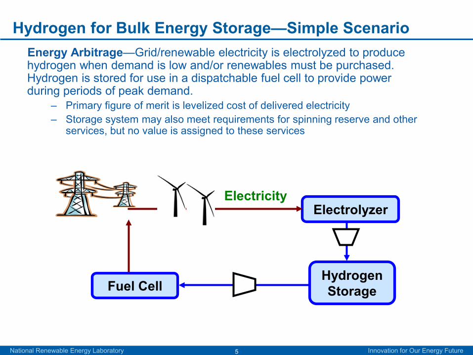
Hydrogen for Bulk Energy Storage—Simple ScenarioEnergy Arbitrage—Grid/renewable electricity is electrolyzed to produce hydrogen when demand is low and/or renewables must be purchased. Hydrogen is stored for use in a dispatchable fuel cell to provide power during periods of peak demand.
– Primary figure of merit is levelized cost of delivered electricity– Storage system may also meet requirements for spinning reserve and other
services, but no value is assigned to these services
Electricity
Hydrogen Storage
Electrolyzer
Fuel Cell

6
Study Framework—System Configuration
50MW for 6 peak hours each weekday (300 MWh/day)Two basic storage system configurations, both using an electrolyzer system to produce hydrogen and a fuel cell system to produce electricity:
– Case 1: Steel tank storage (above ground)– Case 2: Geologic storage
3 timeframes/cost values considered:– Near-term: Up to 2010 (current or high cost)– Mid-term: 2010–2020– Long-term: 2020–2030 (future assumed low cost)
Long-term case meant to represent best-case scenario for hydrogen-based energy storage using stretch goals based on fully mature, optimized hydrogen technologies
National Renewable Energy Laboratory Innovation for Our Energy Future

7
Study Framework—Facility Life Economic Analysis
Financial Assumptions– 40-year plant life (Some equipment will be replaced at more
frequent intervals.)– 10% after-tax internal rate of return– 100% equity financing
Cost Assumptions– Electricity is purchased from the grid during off-peak hours at
3.8¢/kWh (lower-bound cost) or 6¢/kWh (upper-bound case)– Natural gas is purchased at $5/mmBtu for the CAES system
National Renewable Energy Laboratory Innovation for Our Energy Future

8
Study Framework— Facility Life Economic Analysis
Facility Lifecycle Economic Analysis Using the HOMER Model
– NREL distributed generation economic model (https://analysis.nrel.gov/homer)
– Least cost system optimization based on subsystem component costs and resource and load characteristics
– Model output is levelized cost (¢/kWh) of output electricity from the system
National Renewable Energy Laboratory Innovation for Our Energy Future

9National Renewable Energy Laboratory Innovation for Our Energy Future
Develop potentially viable hydrogen production and storage scenarios
Perform a facility lifecycle economic analysis to determine the levelized cost of delivering energy for the hydrogen scenarios
Benchmark against competing technologies on an “apples to apples” basis– Batteries– Pumped hydro – Compressed Air Energy Storage
Benchmarking Study: “Apples to Apples” Analysis

10
Fuel Cell Subsystem
National Renewable Energy Laboratory Innovation for Our Energy Future
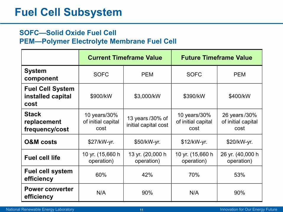
Solid Oxide Fuel Cell (SOFC)Polymer Electrolyte Fuel Cell (PEM) (a.k.a., Proton Exchange Membrane Fuel Cell)
Sources: http://en.wikipedia.org/wiki/Proton_exchange_membrane_fuel_cellhttp://en.wikipedia.org/wiki/Solid_oxide_fuel_cell
11
Fuel Cell Subsystem
Current Timeframe Value Future Timeframe Value
System component SOFC PEM SOFC PEM
Fuel Cell System installed capital cost
$900/kW $3,000/kW $390/kW $400/kW
Stack replacement frequency/cost
10 years/30% of initial capital
cost
13 years /30% of initial capital cost
10 years/30%of initial capital
cost
26 years /30% of initial capital
cost
O&M costs $27/kW-yr. $50/kW-yr. $12/kW-yr. $20/kW-yr.
Fuel cell life 10 yr. (15,660 h operation)
13 yr. (20,000 h operation)
10 yr. (15,660 h operation)
26 yr. (40,000 h operation)
Fuel cell system efficiency 60% 42% 70% 53%
Power converter efficiency N/A 90% N/A 90%
National Renewable Energy Laboratory Innovation for Our Energy Future
SOFC—Solid Oxide Fuel CellPEM—Polymer Electrolyte Membrane Fuel Cell
12
Electrolyzer and Storage Subsystems
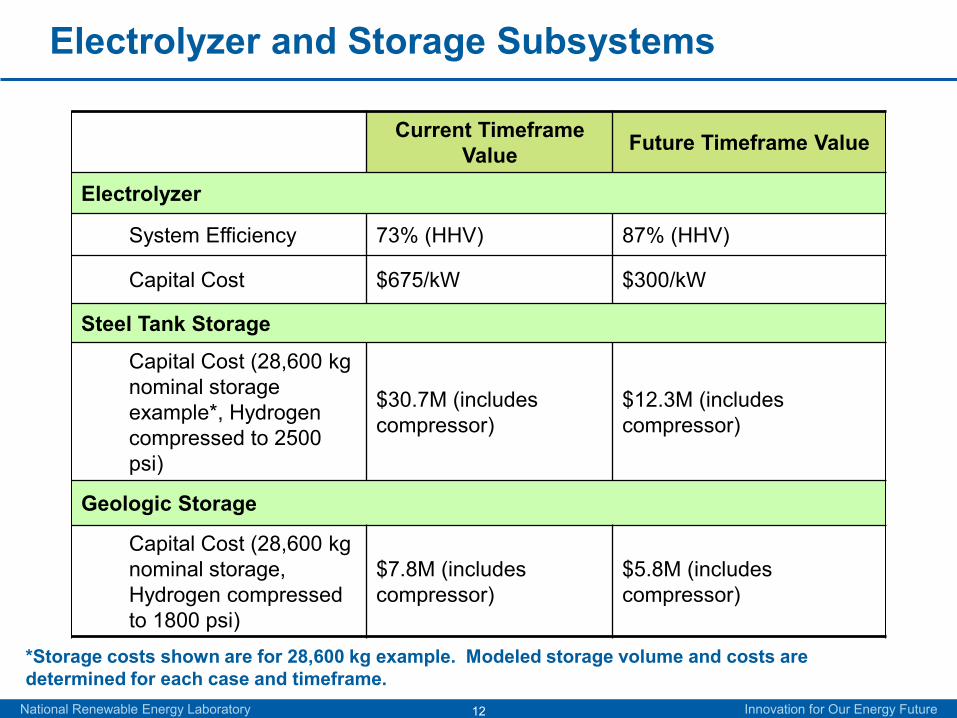
Current Timeframe Value Future Timeframe Value
Electrolyzer
System Efficiency 73% (HHV) 87% (HHV)
Capital Cost $675/kW $300/kW
Steel Tank Storage
Capital Cost (28,600 kg nominal storage example*, Hydrogen compressed to 2500 psi)
$30.7M (includes compressor)
$12.3M (includes compressor)
Geologic Storage
Capital Cost (28,600 kg nominal storage, Hydrogen compressed to 1800 psi)
$7.8M (includes compressor)
$5.8M (includes compressor)
National Renewable Energy Laboratory Innovation for Our Energy Future
*Storage costs shown are for 28,600 kg example. Modeled storage volume and costs are determined for each case and timeframe.

13National Renewable Energy Laboratory Innovation for Our Energy Future
Cost of Energy for PEM Fuel Cell vs. Solid Oxide Fuel Cell
Chart represents “bounding case” information-High Cost Bounding Case: Current timeframe, aboveground storage
- Low Cost Bounding Case: Future timeframe, geologic storage
Current timeframe
Future timeframe

14National Renewable Energy Laboratory Innovation for Our Energy Future
Develop potentially viable hydrogen production and storage scenarios
Perform a lifecycle economic analysis to determine the levelized cost of delivering energy for the hydrogen scenarios
Benchmark against competing technologies on an “apples to apples” basis– Batteries– Pumped hydro – Compressed Air Energy Storage
Benchmarking Study: “Apples to Apples” Analysis
15National Renewable Energy Laboratory Innovation for Our Energy Future
Benchmarking Analysis—Evaluate all Technologies for the Same Scenario
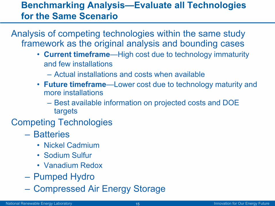
Analysis of competing technologies within the same study framework as the original analysis and bounding cases
• Current timeframe—High cost due to technology immaturity and few installations– Actual installations and costs when available
• Future timeframe—Lower cost due to technology maturity and more installations– Best available information on projected costs and DOE
targetsCompeting Technologies
– Batteries• Nickel Cadmium• Sodium Sulfur• Vanadium Redox
– Pumped Hydro– Compressed Air Energy Storage

16National Renewable Energy Laboratory Innovation for Our Energy Future
Develop potentially viable hydrogen production and storage scenarios
Perform a lifecycle economic analysis to determine the levelized cost of delivering energy for the hydrogen scenarios
Benchmark against competing technologies on an “apples to apples” basis– Batteries– Pumped hydro – Compressed Air Energy Storage
Benchmarking Study: “Apples to Apples” Analysis

17National Renewable Energy Laboratory Innovation for Our Energy Future
Benchmarking Analysis—BatteriesThree Battery TechnologiesNickel Cadmium
– Demonstrated utility-scale project outside Fairbanks Alaska: 13 MWh (26 MW at 30 min.)
Sodium Sulfur– NGK Insulators Ltd. of Japan is currently the only supplier.– Tokyo Electric Power Company (TEPCO) has developed several utility-
scale projects with NGK. Demonstration projects range from 500 kW to 6 MW in scale including two 48-MWh plants.
Vanadium Redox Flow Batteries– Currently, the major suppliers of Vanadium Redox batteries are VRB Power
Systems, Inc. of Canada and Sumitomo Electric Industries (SEI) of Japan. – Demonstrated installations range in size from 3 MW for 1.5 seconds of
storage to 500 kW for up to 10 hours of storage.

18National Renewable Energy Laboratory Innovation for Our Energy Future
Battery Charge Characteristics—NiCd Example
19National Renewable Energy Laboratory Innovation for Our Energy Future
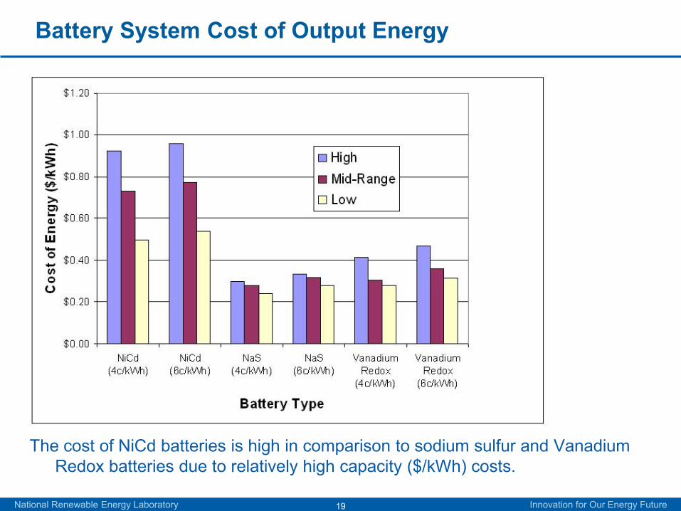
The cost of NiCd batteries is high in comparison to sodium sulfur and Vanadium Redox batteries due to relatively high capacity ($/kWh) costs.
Battery System Cost of Output Energy

20National Renewable Energy Laboratory Innovation for Our Energy Future
Develop potentially viable hydrogen production and storage scenarios
Perform a lifecycle economic analysis to determine the levelized cost of delivering energy for the hydrogen scenarios
Benchmark against competing technologies on an “apples to apples” basis– Batteries– Pumped hydro – Compressed Air Energy Storage
Benchmarking Study: “Apples to Apples” Analysis

21National Renewable Energy Laboratory Innovation for Our Energy Future
Benchmarking Analysis—Pumped Hydro and CAES
Pumped HydroThe first plant built in the United States in 1928–29 featured
two 3-MW reversible turbines. Today, pumped hydro capacity in the United States is about
19,000 MW.
Compressed Air Energy StorageThere are two major CAES installations in Huntorf, Germany
(built in the 1970s) and in McIntosh, Alabama (built in the 1990s).
Plants, built and proposed, range in size from 110 MW to 2700 MW.

22National Renewable Energy Laboratory Innovation for Our Energy Future
Source: Nakhamkin, M., and M. Chiruvolu, Available Compressed Air Energy Storage (CAES) Concepts.
Schematic for Alabama McIntosh 110-MW CAES Plant

23National Renewable Energy Laboratory Innovation for Our Energy Future
Benchmarking Analysis—Pumped Hydro and CAES
Both technologies are low cost relative to hydrogen fuel cells or batteries.

24National Renewable Energy Laboratory Innovation for Our Energy Future
Benchmarking Cost Analysis ResultsHydrogen could be competitive with alternative technologies for the bulk
electricity storage (50 MW, 6 hours) scenario analyzed.– As fuel cell technology matures, electricity could be produced from
geologically stored hydrogen for under 20¢/kWh.– Because of its high energy density, aboveground storage of hydrogen could
be competitive in locations where CAES and pumped hydro are not feasible.

25National Renewable Energy Laboratory Innovation for Our Energy Future
Benchmarking—Other Benefits and Drawbacks of Hydrogen Energy Storage Relative to Alternatives
System OperationBenefits DrawbacksModular (can size the electrolyzer separately from FC to produce extra hydrogen)
Low electrolysis/FC round trip (AC to AC) efficiency (50–55%)Even lower round-trip efficiency when hydrogen is used in a combustion turbine (<40%)
Very high energy density for compressed hydrogen (>100 times the energy density for compressed air at 120 bar ∆P, CC GT)
Hydrogen storage in geologic formations other than salt caverns may not be feasible
System can be fully discharged at all current levels
Electrolyzers and fuel cells require cooling
CostBenefits DrawbacksResearch has potential to drive down costs Use of precious metal catalysts for low-
temperature fuel cellsCurrently high cost relative to competing technologies (>$1,000/kW)
Source: Crotogino and Huebner, Energy Storage in Salt Caverns / Developments and Concrete Projects for Adiabatic Compressed Air and for Hydrogen Storage, SMRI Spring 2008 Technical Conference, Portugal, April 2008.
26National Renewable Energy Laboratory Innovation for Our Energy Future
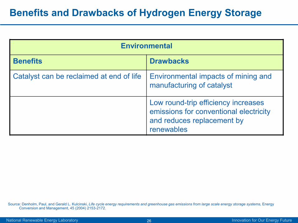
Benefits and Drawbacks of Hydrogen Energy Storage
Environmental
Benefits Drawbacks
Catalyst can be reclaimed at end of life Environmental impacts of mining and manufacturing of catalyst
Low round-trip efficiency increases emissions for conventional electricity and reduces replacement by renewables
Source: Denholm, Paul, and Gerald L. Kulcinski, Life cycle energy requirements and greenhouse gas emissions from large scale energy storage systems, Energy Conversion and Management, 45 (2004) 2153-2172.

27National Renewable Energy Laboratory Innovation for Our Energy Future
Benefits and Drawbacks of Battery Energy Storage
System OperationBenefits DrawbacksModular Battery voltage to current relationship
limits the amount of energy that can be extracted, especially at high current
Mid range to high round trip efficiency (65–75%)
CostBenefits DrawbacksSodium sulfur and Vanadium Redox battery system cost
Nickel cadmium battery system cost
High round-trip efficiency reduces arbitrage scenario costs
EnvironmentalBenefits Drawbacks
Toxic and hazardous materialsSource: EPRI-DOE Handbook of Energy Storage for Transmission and Distribution Applications, 2003, EPRI, Palo Alto, CA and the U.S. Department of Energy,
Washington, DC.

28National Renewable Energy Laboratory Innovation for Our Energy Future
Benefits and Drawbacks of Pumped Hydro Energy Storage
System OperationBenefits DrawbacksWell established and simple technology System requires large reservoir of water (or
suitable location for reservoir)High round-trip efficiency (70–80%) System requires mountainous terrain
Extremely low energy density (0.7 kWh/m3)Cost
Benefits DrawbacksInexpensive to build and operate
EnvironmentalBenefits DrawbacksNo toxic or hazardous materials Large water losses due to evaporation,
especially in dry climatesHabitat loss due to reservoir floodingStream flow and fish migration disruption
Source: Denholm, Paul, and Gerald L. Kulcinski, Life cycle energy requirements and greenhouse gas emissions from large scale energy storage systems, Energy Conversion and Management, 45 (2004) 2153-2172.
29National Renewable Energy Laboratory Innovation for Our Energy Future
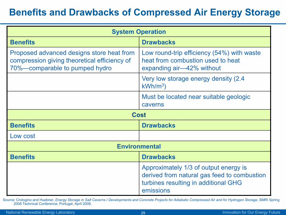
Benefits and Drawbacks of Compressed Air Energy Storage
System OperationBenefits DrawbacksProposed advanced designs store heat from compression giving theoretical efficiency of 70%—comparable to pumped hydro
Low round-trip efficiency (54%) with waste heat from combustion used to heat expanding air—42% withoutVery low storage energy density (2.4 kWh/m3)Must be located near suitable geologic caverns
CostBenefits DrawbacksLow cost
EnvironmentalBenefits Drawbacks
Approximately 1/3 of output energy is derived from natural gas feed to combustion turbines resulting in additional GHG emissions
Source: Crotogino and Huebner, Energy Storage in Salt Caverns / Developments and Concrete Projects for Adiabatic Compressed Air and for Hydrogen Storage, SMRI Spring 2008 Technical Conference, Portugal, April 2008.

30National Renewable Energy Laboratory Innovation for Our Energy Future
Conclusions
Hydrogen has several important advantages over competing technologies, including:– Very high storage energy density (170 kWh/m3 vs. 2.4 for CAES
and 0.7 for pumped hydro)• Allows for potential economic viability of above-ground storage
– Relatively low environmental impact in comparison with other technologies
The major disadvantage of hydrogen energy storage is cost. – Research and deployment of electrolyzers and fuel cells may
reduce cost significantly.

31
Thank You
Questions?