scheduling in non-blocking buffered three-stage … in non-blocking buffered three-stage switching...
TRANSCRIPT
Scheduling in Non-Blocking BufferedThree-Stage Switching Fabrics
Nikos Chrysos and Manolis Katevenis‡
Foundation for Research and Technology - Hellas (FORTH), member of HiPEAC
Abstract— Three-stage non-blocking switching fabrics are thenext step in scaling current crossbar switches to many hundredsor few thousands of ports. Congestion management, however, isthe central open problem; without it, performance suffers heav-ily under real-world traffic patterns. Schedulers for bufferlesscrossbars perform congestion management but are not scalable tohigh valencies and to multi-stage fabrics. Distributed scheduling,as used in buffered crossbars, is scalable but has never beenscaled beyond crossbar valencies. We combine ideas from centraland distributed schedulers, from request-grant protocols andfrom credit-based flow control, to propose a novel, practicalarchitecture for scheduling in non-blocking buffered switchingfabrics. The new architecture relies on multiple, independent,single-resource schedulers, operating in a pipeline. It: (i) isolateswell-behaved against congested flows; (ii) provides throughputin excess of 95% under unbalanced traffic, and delays that suc-cessfully compete again output queueing; (iii) provides weightedmax-min fairness; (iv) directly operates on variable-size packetsor multi-packet segments; (v) resequences cells or segments usingvery small buffers; and (vi) can be realistically implemented for a1024×1024 reference fabric made out of 32×32 buffered crossbarswitch elements. This paper carefully studies the many intricaciesof the problem and the solution, discusses implementation, andprovides performance simulation results.
1 . INTRODUCTION
Switches are increasingly used to build the core of routers,cluster and server interconnects, other bus-replacement de-vices, etc. The desire for scalable systems implies a demandfor switches with ever-increasing valency (port counts). Be-yond 32 or 64 ports, single-stage crossbar switches are quiteexpensive, and multi-stage interconnection networks (switch-ing fabrics) become preferable; they are made of smaller-valency switching elements, where each such element is usu-ally a crossbar. It has been a longstanding objective of design-ers to come up with an economic switch architecture, scalingto large port-counts, and achieving sophisticated quality-of-service (QoS) guarantees under unfavorable traffic patterns.This paper addresses that challenge.
The performance of switching fabrics is often severely hurtby inappropriate decisions on how to share scarce resources.Output contention is a primary source of such difficulties: in-put ports, unaware of each other’s decisions, may inject trafficfor specific outputs that exceeds those outputs’ capacities. Theexcess packets must either be dropped, thus leading to poor
‡ The authors are also with the Dept. of Computer Science, University ofCrete, Heraklion, Crete, Greece.
performance, or must wait in buffers; buffers filled in thisway may prevent other packets from moving toward theirdestinations, again leading to poor performance. Toleratingoutput contention in the short term, and coordinating thedecisions of input ports so as to avoid output contention inthe long run is a complex distributed scheduling problem;flow control and congestion management are aspects of thatendeavor. This paper contributes toward solving that problem.
Switching fabrics may be bufferless or buffered. Bufferlessfabrics merely steer traffic, without being able to delay someof it in favor of other. Such fabrics cannot tolerate any outputcontention (or contention for internal links), thus they imposevery stringent requirements on the scheduling subsystem.Buffered switching fabrics, on the other hand, contain someinternal temporary storage so as to tolerate contention up toa certain extent. Buffered fabrics are clearly preferable, andmodern integrated circuit technology makes them feasible.This paper assumes such buffered fabrics, and is concernedwith how to reduce buffer size and how to control its use.
Buffers inside switching fabrics are usually small [24], soas to avoid off-chip memory at the switching elements, aswell as to better control delays through the fabric. In orderfor the small buffers not to overflow, backpressure protocolsare used. Indiscriminate backpressure stops all flows sharinga buffer when that buffer fills up; it leads to poor performancedue to buffer hogging –a phenomenon with effects similarto head-of-line blocking. Per-flow buffer reservation and per-flow backpressure signaling overcome these shortcomings,but become expensive with increasing number of flows. Per-destination flow merging [10] alleviates this cost. One practicalcompromise is to dynamically share the available buffer spaceamong flows destined to multiple (as many as possible) distinctoutput ports, as in the ATLAS I chip [25]. A related, improvedmethod is to dynamically detect congestion trees, allocate “set-aside queues (SAQ)” to them, and use per-SAQ backpressure[26].
This paper proposes and evaluates an alternative, novelscheduling, congestion management, and flow control ar-chitecture: when heavy traffic is detected, input ports haveto first request and be granted permission before they cansend any further packets. Requests are routed to and grantsare generated by a scheduling subsystem. This subsystem,which can be central or distributed, consists of independent,simple, per-output and per-input, single-resource schedulers,
To appear in Proc. Infocom 2006 Conference – Early Draft, August 2005 1
operating in parallel. The architecture has conceptual analogiesto scheduling in buffered crossbars (combined input-crosspointqueueing - CICQ) [18] [20]. Compared to the alternativeslisted above, the new method: (i) operates robustly under alltraffic patterns, not just under “typical” traffic; (ii) has thepotential to economize on buffer space; and (iii) applies toscalable non-blocking fabrics that employ multipath routing.Other previously proposed scheduling schemes for 3-stagenon-blocking fabrics assumed one unbuffered stage, while ournew architecture applies to fully buffered fabrics, thus yieldingsignificantly higher performance. Further discussion on thesecomparisons appears in section 2 on related work. Beforethat, we describe our scheduling architecture and the switchingfabric where it fits.
1.1 Non-Blocking Three-Stage Fabrics
Switching fabrics are said to present internal blocking wheninternal links do not suffice to route any combination offeasible I/O rates, hence, contention may appear on internallinks as well –in addition to output ports. Otherwise, a fabricis called non-blocking when it can switch any set of flowsthat do not violate the input and output port capacity limits.Although internal blocking clearly restricts performance, mostcommercial products belong to the first category, because apractical, robust, and economic architecture for non-blockingfabrics has not been discovered yet. However, neither has itbeen proven that such architectures do not exist. This papercontributes to the search for practical, robust, and economicnon-blocking switching fabrics.
Low-cost practical non-blocking fabrics are made usingClos networks [27]; the basic topology is a three-stage fabric,while recursive application of the principle can yield 5-stage networks, 7-stage, etc. One of the parameters of Closnetworks, m/n, controls the speed expansion ratio –somethinganalogous to the “internal speedup” used in combined input-output queueing (CIOQ) architectures: the number of middle-stage switches, m, may be greater than or equal to thenumber of input/output ports per first/third-stage switch, n.In this paper, we assume m = n, i.e. no speedup –theaggregate throughput of the middle stage is no higher thanthe aggregate throughput of the entire fabric. In this way,the fabrics considered here are the lowest-cost practical non-blocking fabrics, oftentimes also referred to as Benes fabrics.
In order for a Benes fabric to operate without internal block-ing in a packet switching set-up, multipath routing (inversemultiplexing) must be used [28] [29]: each flow (as definedby an input-output port pair) is distributed among all middle-stage switches, in a way such as to equalize the rates of theresulting sub-flows. The middle-stage switches can be thoughtof as parallel slices of one, faster virtual switch, and inversemultiplexing performs load balancing among these slices. Suchmultipath routing introduces out-of-order packet arrivals at theoutput ports; we assume that egress linecards perform packetresequencing, so as to ensure in-order eventual packet delivery.Our scheduling system specificly bounds the extent of packetmis-ordering, thus also bounding the required size of reorder
I (1,1)
I (1,i)
I (j,i)
I (j,32)
I (32,1)
I (32,i)
I (1,32)
I (j,1)
I (32,32)
B1
Bj
B32
O (j,i)
O (j,32)
O (32,1)
O (32,i)
O (1,32)
O (j,1)
O (1,i)
O (32,32)
O (1,1)
Sin (32,32)
���� �� ��������
Cj
C32
Ingress (VOQ)Linecards
EgressLinecards
A32
(1) request
out(1,1) in(1,1)
flow−control
S S
out (32,32)S
"use B slice 32"
(3) packet
***flow−control***flow−control
buffer credits
(4) fabric−output
Aj
A1
Pipelined, Single−ResourceAdmission Schedulers
creditschedulers schedulers
grant
B32Bj
A32Aj
I32Ii
(2) grant/credit
C1
I1
B1
A1
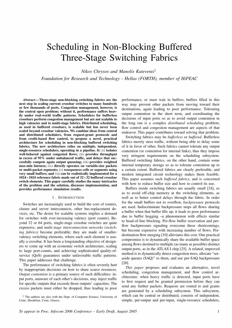
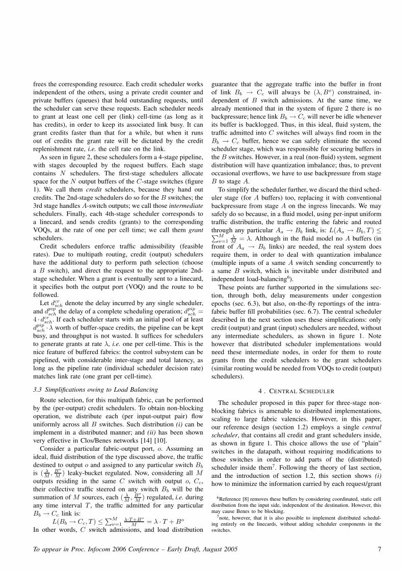
Fig. 1. System assumed in this paper. Our reference design (section 1.2)uses valency N=1024, switch element size M=32; a first (short) operationdescription appears in section 1.3, par. 4; C-B flow-control is superimposedby the request-grant (credit-based) flow-control, described in (extend in) [11];our system uses C-B link buffer flow-control for a few unsolicited packetsthat (skip) “bypass” the request-grant procedure.
buffers, so that the latter can fit on-chip using modern ICtechnology for our 1024-port reference fabric –see section 4.2.
1.2 Reference Design: a 1024×1024, 10 Tb/s Fabric
Although the architecture proposed and evaluated in thispaper is quite general and applicable to many networks, ourmotivation for developing it, and our primary benchmark for it,is an example next-generation fabric challenge, that is realisticas a commercial product in the second half of this decade.This “reference design”, shown in figure 1, is a 1024×1024switching fabric (valency N=1024), made out of 96 single-chip 32×32 switching elements (3 stages of 32 switch chipsof valency M=32 each), plus one (1) scheduler chip, shown inthe top middle of the figure; linecards are not included in thechip counts. We name the first, second, and third switch stagesas A, B, and C respectively. Although this topology looks likecurrent “byte-sliced” commercial switch products, where eachcell is sliced into M subunits and concurrently routed throughall B switches, our system is very different: cells (actually:variable-size segments) are routed intact (unsliced) throughone of the B switches each, asynchronously with each other;resequencing is provided in the egress linecards.
The scheduler chip is connected to each A switch via onelink, and to each C switch via another link, for a total 64 links(not shown in the figure), just like each switch chip has 64I/O links (32 in, 32 out). An implementation issue, not shownin figure 1, is the direction of each scheduler link, as well ashow backpressure signals are transmitted from C chips to Bchips, from B to A, and from A to linecards; we are currentlyworking on these issues. We consider that the line rate of eachlink is on the order of 10 Gbits/s, limited mostly by the powerconsumption of the switch chip I/O transceivers (roughly upto 320 Gb/s aggregate incoming throughput, plus 320 Gb/soutgoing, per chip).
To appear in Proc. Infocom 2006 Conference – Early Draft, August 2005 2

We assume links carry variable size segments, each con-taining one or more variable-size packets or fragments thereof,as in [23], so as to eliminate padding overhead (if segmentshad fixed size) and reduce header and control overhead (bycarrying multiple small packets inside a segment). Linecardsare assumed to contain (large, off-chip) virtual-output queues(VOQ) in the ingress path, and (small, on-chip) resequencingand reassembly buffers in the egress path. No (large, off-chip)output queues are needed, since we do not need or use anyinternal speedup; in other words, this architecture has the sameadvantages as variable-packet-size buffered crossbars [22]. Weassume that individual switch chips are buffered crossbars, likeour recent chip design [22] which proved their feasibility inthe 2006-08 time frame for size 32×32, with few-Kilobytebuffers per crosspoint, at 10 Gb/s line rate. We chose bufferedcrossbars because of their simplicity, scheduling efficiency,and support for variable-packet-size operation.
We chose the parameters of our reference design so thatthe scheduling subsystem can fit in a single chip, althoughthis subsystem could also be distributed among multiple chips.To achieve a single-chip scheduler, we have to ensure thatthe aggregate throughput of its traffic does not exceed 1/Mtimes the aggregate data throughput of the fabric, where M=32is the switch valency, for the following reasons. Since theM switches in each fabric stage can pass the aggregate datathroughput, it follows that the one scheduler chip can passthe aggregate control throughput, if the latter is 1/M timesthe former. The scheduler chip is connected to each A and Cchip via one link; that link suffices to carry the control trafficthat corresponds to the M data links of the switch chip, ifcontrol traffic is 1/M times the data traffic.
For these relations to hold for M = 32, we assume thatthe maximum-size segment is 64 Bytes or larger. Under heavytraffic, almost all segments are of maximum size, because theyare allowed to carry multiple packets (or packet fragments)each. The control traffic, per segment, consists of a request(10 bits), a grant (10 bits), and a credit (5 bits). Hence,the data throughput, for a switch, per segment, is 1024 bits(512 entering, 512 exiting), while the control throughput,for the scheduler, per segment, is 25 bits (15 entering, 10exiting); the resulting control-to-data ratio is 25/1024 ≈ 1/41(bidirectional), or 15/512 ≈ 1/34 (entering) and 10/512 ≈1/52 (exiting). For the control information format, see section5.1.
1.3 Our Admission Scheduling Architecture
The basic idea of our scheduler is that, under heavy traffic,ingress ports have to request and be granted permission beforethey can send a segment to the fabric. The request-granthandshake incurs some delay, but that delay is in parallel with–hence masked by– the (VOQ) input-queueing delay. Onlyunder light load would this extra delay be visible, but weassume that the request-grant protocol is not used for light-load flows. This point is further discussed in section 1.5 whilethe bulk of this paper concerns fabric operation under heavyload.
The request-grant protocol economizes on buffer spacerelative to per-flow buffer reservation and backpressure. Ef-fectively, instead of first letting data occupy buffers and thenscheduling among the flows to which these data belong (“cor-rective” congestion management), we schedule first amongcompeting requests and then let into the fabric only the datathat are known to be able to quickly get out it (“preventive”or admission-oriented congestion management).
Schedulers for bufferless switches (usually crossbars) servethe same preventive function, but have a much harder timebecause they must enforce absolute admissibility of the traffic,per time-slot. Our scheduler only has to enforce admissibilityover a longer time window, because the fabric contains internalbuffers. This time window serves to mask the latency ofthe scheduling pipeline. At the same time, buffers allowsome overprovisioning of traffic admissions. These excessadmissions mask out scheduling inefficiencies (not being ableto simultaneously match all inputs to all outputs). Thus,instead of using (expensive) internal throughput speedup, asin bufferless crossbars, we use admissions overprovisioning,which is almost for free given the low cost of buffer memory inmodern chips. In essence, we achieve the scheduling efficiencyof buffered crossbars, but at a cost that grows with1 O(N ·
√N)
instead of O(N2).Our admission method is realized by independent per-
output and per-input single-resource schedulers, working inparallel (figure 1). Input requests specify the flow’s outputport, and are routed to the scheduler for that port. Requestsare queued in front of the proper per-output (credit) scheduler;these queues often degenerate to mere counters. Each per-output scheduler generates grants after first allocating spacein that output’s buffer2. Grants can be generated according toa desired quality-of-service (QoS) policy, e.g. weighted roundrobin (WRR) / weighted fair queueing (WFQ). When the datathat were granted eventually depart through that output, thescheduler is notified so as to re-allocate that buffer space.Thus, the rate of data departures indirectly regulates the rateof grant generation, while buffer size (minus control-protocolround-trip time (RTT)) determines the amount of admissionsoverprovisioning.
Multiple per-output schedulers may simultaneously generategrants for a same input port. A per-input scheduler serializesthese in a desired order and forwards them to the input at aconvenient rate. Per-output and per-input schedulers work inparallel, asynchronously from each other, in a pipeline fashion(they can even be in separate chips). As long as each single-resource scheduler maintains a decision rate of at least oneresult per segment time, admissions proceed at the proper rate.
The scheduling subsystem principles and operation are dis-cussed in detail in section 3; the central scheduler organization
1each switch has√
N ports, hence N crosspoint buffers; there are√
N
switches per stage, hence 3·√
N in the entire fabric. Thus, there are 3·N ·√
N
crosspoint buffers in the fabric.2space should in general be reserved for intermediate-stage buffers as well;
however, it turns out that, because the fabric is non-blocking, no serious harmresults if such allocation is omitted –see section 3.3.
To appear in Proc. Infocom 2006 Conference – Early Draft, August 2005 3
and implementation is discussed in section 4.
1.4 Contributions and Results Achieved
First, this paper conducts a careful study of this novelscheduling architecture, its parameters, and its variants. Weconsider this class of architectures very interesting becausethey perform the function of bufferless-crossbar schedulers,but at the high efficiency of buffered-crossbar scheduling,while using significantly less buffer space than buffered cross-bars, and while being scalable to high-valency fabrics.
Second, the proposed architecture switches equally wellfixed-size cells or variable-size (multi-packet) segments, be-cause it only uses independent single-resource schedulersthroughout. Thus, it retains the advantages of buffered cross-bars: no padding overhead, thus no internal speedup needed,hence no (large, off-chip) output queues needed, either. Oursimulations presented in this paper version are mostly forfixed-size cells, because we wanted to compare our results toalternative architectures that operate using cells. However, wedo have simulations showing smooth operation with variable-size segments, and we will have more results on that in thefinal paper version.
Third, advanced QoS policies can be straightforwardlyimplemented in the proposed architecture. For example, wesimulated the system using WRR/WFQ admission schedulers:under inadmissible traffic (persistently backlogged VOQs),the system distributes input and output port bandwidth in aweighted max-min fair manner; up to now, this had only beenshown for single-stage buffered crossbars [20].
Fourth, we quantify buffer space requirements, using sim-ulations. Interestingly, for good performance, a single RTT-window buffer per-crosspoint suffices, provided that this buffersize is at the same time large enough for several segments(cells) to fit into it (RTT is the control protocol round-triptime). As long as crosspoint buffers are larger than one RTT-window each, it appears that performance is sensitive to thenumber of segments per output port that can be pending insidethe fabric at once. The (excellent) performance results listedin the next paragraph are achieved with crosspoint buffers onthe order of ten (10) segments each, and assuming that theoverall scheduling RTT is equal to 10 segment times.
Finally, the new architecture achieves excellent performancewithout any internal speedup. Under uniform traffic, the sys-tem delivers 100% throughput, and delay performance within1.5 times that of pure output queueing (OQ), under burstytraffic, and within 4 times that of OQ under smooth traffic;(results obtained using round-robin schedulers and fabric sizeup 256 × 256 made of 16 × 16 switches). Under unbalancedtraffic, the simulated throughput exceeds 95%. Under hot-spot traffic, with almost all output ports being congested, thenon-congested outputs experience negligible delay degradation(relative to uniform traffic); at the same time, the congestedoutputs are fully utilized (100% load). Compared to bufferless3-stage Clos fabrics [7], our architecture performs much better,and, at the same time, uses a much simpler scheduler.
For the 1024×1024 reference design (section 1.2), theseperformance results can be achieved with 780 KBytes of totalbuffer memory per (32×32) switch chip, assuming the overallscheduling RTT can be kept below 600 ns, and assuming64 Byte maximum segment size (hence, 12 segments percrosspoint buffer). Under the same assumptions, 25 KBytesof reorder buffer suffice in each egress linecard. Alternatively,if the scheduling RTT is as high as 3.2 µs, if we increasemaximum segment size to 256 Bytes (so as to reduce headeroverhead), and if we increase crosspoint buffer size to 16segments = 4 KBytes (for even better performance), thenbuffer memory per switch chip will be 4 MBytes (feasibleeven today), and reorder buffer size will be 128 KBytes.
Comparisons to related work appear in section 2. The sched-uler is discussed in sections 3 and 4. Performance simulationresults are presented in section 6.
1.5 Eliminating Request-Grant Latency under light Load
The request-grant protocol adds a round-trip time (RTT)delay to the fabric response time. For heavily loaded flowsthis RTT delay is negligible. However, under light traffic,it is desirable to avoid that extra delay in latency-sensitiveapplications, e.g. cluster/multiprocessor interconnects. We arecurrently studying such protocols, and we have promisingpreliminary simulation results. We will have concluded thisstudy and will report the results in the final version of thepaper.
The basic idea is that every input is allowed to send asmall number of cells/segments without first requesting andreceiving a grant. If it wants to send more cells before theseoriginal ones have exited the fabric (as recognized by creditscoming back), then it has to follow the normal request-grantprotocol. Under light load, credits will have returned before theflow wishes to send new cells, thus allowing continued low-latency transmission. Under heavy load, the system operates asdescribed in the rest of the paper. To guard against the case ofseveral inputs by coincidence sending at about the same time“free” cells to a same output, thus creating a congestion tree,we are currently evaluating a solution whereby “free” cells and“request-grant” cells travel through separately reserved bufferspace (and are resequenced in the egress linecard).
2 . RELATED WORK
2.1 Per-Flow Buffers
In a previous study [10], we considered a buffered Benesfabric where congestion management was achieved using per-flow buffer reservation and per-flow backpressure signaling. Toreduce the required buffer space from O(N 2) down to O(N)per switching element, where N is the fabric valency, weintroduced per-destination flow merging. That system providesexcellent performance. However, the required buffer space, atleast in some stages, is M ·N , where M is the switch valency.In our reference design, M is relatively large in order to reducethe number of hops; thus, either the first or the third stagewould need switches containing 32 K “RTT” windows each,which is rather large. Furthermore, the buffers in this space
To appear in Proc. Infocom 2006 Conference – Early Draft, August 2005 4
are accessed in ways that do not allow partitioning them per-crosspoint.
This paper addresses those practical problems: we only useO(M2) buffer space per switch (only 1 K windows for thereference design, although the window here is larger than in[10]), explicitely partitioned and managed per-crosspoint. Thispartitioning allows variable-size segment operation. Further-more, the present architecture can provide WRR-style QoS,which would be quite difficult in [10], where merged-flowweight factors would have to be recomputed dynamicallyduring system operation.
2.2 The Parallel Packet Switch (PPS)
The Parallel Packet Switch (PPS) [14] [15] is a three-stagefabric, where the large (and expensive) buffers reside in thecentral-stage. First and third stage switches serve a singleexternal port each. By increasing the number of central ele-ments, k, the PPS can reduce the bandwidth of each individualmemory module, or equivalently provide line-rate scalabil-ity. Essentially, the PPS operates like a very-high-throughputshared buffer, which is composed of k interleaved memorybanks; one expensive and complex component of the designis how to manage the shared buffer data structures (queuepointers etc.) at the required very high rate, hence necessarilyin a distributed fashion. The PPS provides port-rate scalability,but does not provide port-count (N ) scalability. One couldmodify the PPS for port-count scalability, by modifying eachfirst-stage element from a 1-to-k demultiplexor serving onefast input to an M × k switch serving M slower inputs;correspondingly, each third-stage element must be changedfrom a k-to-1 multiplexor to a k × M switch. However,this latter modification would require dealing with outputcontention on the new “subports”, i.e. per-subport queuesalong the stages of the PPS. Effectively, then, this radicallyaltered PPS would have to solve the same problems that thispaper solves for the input-queued fabric.
2.3 Memory-Space-Memory ClosClos fabrics containing buffers in the first and last stages, but
using bufferless middle stage, and having a central scheduler,have been implemented in the past [6] and further studiedrecently [7]. These schedulers are interesting but complexand expensive (they require two iSLIP-style exact matchingto be found, some of which among N ports, per cell-time).Like iSLIP, they can provide 100% throughput under uniformtraffic, but performance suffers under non-uniform load pat-terns. In-order delivery results from (or is the reason for) themiddle stage being bufferless in those architectures. This paperdemonstrates that the cost of allowing out-of-order traffic, andthen reordering it in the egress linecard, is minimal. In returnfor this cost, the use of buffered crossbars in all stages of ourarchitecture provides much better performance with a muchmore scalable scheduler.
2.4 Regional Explicit Congestion Notification (RECN)
A promising method to handle the congestion in multistageswitches has recently been presented in [26]. A key point
is that sharing a queue among multiple flows will not harmperformance as long as the flows are not congested. Basedon this observation, [26] uses a single queue for all non-congested flows, and dynamically allocates a set-aside-queue(SAQs) per congestion tree, when the latter are detected.Congestion trees may be rooted at any output or internalfabric link, and their appearance is signaled upstream via“regional explicit congestion notification (RECN) messages.We consider [26] and our scheme as the two most promisingarchitectures for congestion management in switching fabrics.Precisely comparing them to each other will take a lot of work,because the two systems are very different from each other,so the comparison results depend a lot on the relative settingsof the many parameters that each system has.
Nevertheless, a few rough comparisons can be made here:(i) RECN saves the cost of the central scheduler, but atthe expense of implementing the RECN and SAQ func-tionality (which includes a content-addressable memory) inevery switch; (ii) under light load, RECN uses very littlethroughput for control messages; however, some amount ofcontrol throughput must be provisioned for, to be used in caseof heavy load, and this may not differ much from controlthroughput in our system; (iii) RECN has not be studied forfabrics using multipath routing, like our system does, henceit is not known whether and at what cost RECN applies tonon-blocking fabrics; (iv) RECN works well when there area few congestion trees in the network, but it is unknownhow it would behave (and at what cost) otherwise, whileour system operates robustly independent of the number ofcongested outputs (no internal links can ever be congestedin our system); (v) contrary to our system, in RECN, duringthe delay time from congestion occurrence until SAQ setup,uncongested flows suffer from the presence of congested ones;(vi) RECN relies on local measurements to detect congestion;these measurements are performed on an output buffer; forreliable measurement (especially under bursty traffic or withinternal speedup), that buffer cannot be too small; at the sametime, RECN signaling delay translates into SAQ size; the sumof all these required buffer sizes may end up not being muchsmaller than what our system requires.
2.5 End-to-end Rate Regulation
Pappu, Turner, and Wong [16] [17] have studied a rateregulation method analogous to ours. Both systems regulatethe injections of packets into a fabric so as to prevent theformation of saturation trees.
However, the Pappu system foresees a complex and lengthycommunication and computation algorithm; to offset that cost,rate adjustments are made fairly infrequently (e.g., every 100µs). Such long adjustment periods (i) hurt the delay of newpackets arriving at empty VOQs; and (ii) do not preventbuffer hogging and subsequent HOL blocking during transientphenomena in between adjustment times, when those buffersare not proportionally sized to the long adjustment period.Our scheme operates at a much faster control RTT, with muchsimpler algorithms, basically allocating buffer space, and only
To appear in Proc. Infocom 2006 Conference – Early Draft, August 2005 5

indirectly regulating flow rates. The result is low latencies andprevention of buffer hogging. Additionally, Pappu e.a. do notaddress the size of resequencing buffers, while we provide aquite low bound for that size.
3 . SCHEDULING THREE-STAGE NON-BLOCKING FABRICS
This section shows how to properly schedule, using in-dependent and pipelined schedulers, a N -port non-blockingthree-stage fabric, with as few as O(M ) queues per M × Mswitch (M=
√N ). To that end, we combine ideas from buffer-
less and buffered fabrics. The first scheduler to be presentedhere is derived from first principles, and for that reason it isexpensive and complicated; then we simplify it in sections 3.3and 4.
3.1 Key Concepts
The first idea is to use an independent scheduler for eachfabric buffer (this will later be relaxed). A packet (segment)will only be injected into the fabric after all schedulers for allbuffers along its route have reserved space for the packet. Firstreserving then injecting trades latency (for the request-grantround-trip time (RTT)) for buffer space economy: buffers areonly occupied by cells that are guaranteed to move forward,instead of being uselessly held by congested-flow cells, withbackpressure protocols.
We start buffer-space reservations from the last (output)fabric stages, moving left (to the inputs), one stage at a time;notice that this is precisely opposite to how cells progressunder backpressure protocols. The direction chosen ensuresthat each reservation, when performed, is on behalf of a cellthat is guaranteed not to block inside the buffer: buffer spacehas already been reserved for that cell in the next downstreambuffer. Hence, cells will be allowed to move freely, withoutneed for any backpressure to ever hold them back, and withoutdanger of any buffer overflowing.
Of course, inputs and outputs play symmetric roles in switchscheduling. When consuming buffers in the downstream direc-tion, as with backpressure protocols, the danger is for manyinputs to simultaneously occupy buffers with cells going to thesame output: output contention delays cell motion. Conversely,when reserving buffers in the upstream direction, like we dohere, the danger is for many outputs to simultaneously reservespace for cells to come from the same input: input contentiondelays cell arrivals3. What limits input contention in our caseis that buffer reservations constitute a second pass through thefabric, after requests have traversed once from inputs to theper-output scheduler. Thus, the only way for an input to receivean excessive number of reservations from multiple outputs isfor other inputs not to have sent any requests to those outputs.Our recent paper [11] studied this issue in a single-stage fabricequipped with small output queues. There, we found that,when each scheduler reserves space for multiple inputs inparallel, the bad effects of “synchronization” are confined; onthe order of ten cells per output port sufficed there. We observe
3this is analogous to “bad synchronization” of round-robin pointers in theinitial, suboptimal iSLIP idea [5].
S
S
S
S
S
S
S
S
O(1,1)
O(1,2)
O(2,1)
O(2,2)B2−C2B2−
C1
B1−C2
B1−C1
A2−B1
A1−B2
A1−B1
A2−B2
Req
uest
Buf
fersS
Req
uest
Buf
fers
Req
uest
Buf
fers
Req
uest
Buf
fers
S
S
S SA2−B1
B2−C2
A1
A2 B2
B1 C1
C2
I(1,1)
I(2,2)
I(2,1)
I(1,2)
A1−B1S S S
A2−B2
A1−B2 B2−C1
B1−C2 O(2,1)
O(2,2)
O(1,1)
O(1,2)
B1−C1I(1,1)
I(1,2)
I(2,1)I(2,2)
4th (input) stage 3nd (A−B) 2nd (B−C)
(3) inject packets
from B,
in fabric
grant (2)
replenished credits from A, from C
4−stage pipeline of credit schedulers(one "time−slot" delay per−stage)
1st (output) stage
(1) request ( "ask for credits")
VOQs
Fig. 2. Pipelined buffer scheduling in a 4 × 4, three-stage non-blockingfabric.
a similar result in this paper, except that the number of cellsper output is higher in the present paper, partly due to thebuffered crossbar organization, which partitions each outputqueue’s space into many smaller per-input spaces.
Observe that similar conflicting decisions also occur inbuffered crossbar scheduling: a set of inputs may concurrentlyforward packets to a same output. However, these inputs arenot blocked following their first, suboptimal decisions: theymay continue sending cells to other outputs. If an outputreceives excess cells in this way, backpressure from thecrosspoints will force the inputs to prefer other outputs. Thisis the reason why buffered crossbars yield good performancewithout explicit coordination between the port schedulers. Abuffered crossbar uses order N cell buffers per output toachieve this result; in some sense, this is a waste of resources.Our results indicate that we can do equally well with buffersquite smaller than N cells per output 4.
3.2 Buffer Scheduling
Switch schedulers match inputs to outputs (or to internallinks). Schedulers for bufferless switches do that precisely, pertime-slot [4][5][7]. On the other hand, if there is a buffer ofsize Bo in front of each output (or internal) link, the schedulingconstraint is relaxed: the amount of traffic admitted to that linkcan be as much as Bo per time-slot, but over any interval oflength T that amount of traffic must not exceed λ · T + Bo,where λ is the link rate5.
We start with a conceptual scheduler, shown in figure 2, thatadmits this “window-type” feasible traffic; we will simplify itin the next sections. It consists of single-resource schedulersper output and per internal link. Each scheduler hands outcredits for the buffer space in front of the correspondinglink. Credits are replenished when the admitted cell eventually
4as described in section 4.4, our system features a “backpressure” mecha-nism that prevents persistent buffer reservations that conflict on inputs.
5as mentioned already, when buffer space is reserved for every cell in everybuffer, backpressure is not needed and cells are never dropped; in the absenceof backpressure, each link always empties its buffer at peak rate λ. Noticethat this also yields an upper bound for cell delay through the fabric: numberof stages, times buffer size per stage, divided by link rate λ.
To appear in Proc. Infocom 2006 Conference – Early Draft, August 2005 6
frees the corresponding resource. Each credit scheduler worksindependent of the others, using a private credit counter andprivate buffers (queues) that hold outstanding requests, untilthe scheduler can serve these requests. Each scheduler needsto grant at least one cell per (link) cell-time (as long as ithas credits), in order to keep its associated link busy. It cangrant credits faster than that for a while, but when it runsout of credits the grant rate will be dictated by the creditreplenishment rate, i.e. the cell rate on the link.
As seen in figure 2, these schedulers form a 4-stage pipeline,with stages decoupled by the request buffers. Each stagecontains N schedulers. The first-stage schedulers allocatespace for the N output buffers of the C-stage switches (figure1). We call them credit schedulers, because they hand outcredits. The 2nd-stage schedulers do so for the B switches; the3rd stage handles A-switch outputs; we call those intermediateschedulers. Finally, each 4th-stage scheduler corresponds toa linecard, and sends credits (grants) to the correspondingVOQs, at the rate of one per cell time; we call them grantschedulers.
Credit schedulers enforce traffic admissibility (feasiblerates). Due to multipath routing, credit (output) schedulershave the additional duty to perform path selection (choosea B switch), and direct the request to the appropriate 2nd-stage scheduler. When a grant is eventually sent to a linecard,it specifies both the output port (VOQ) and the route to befollowed.
Let dcrsch denote the delay incurred by any single scheduler,
and dpip
sch the delay of a complete scheduling operation; dpip
sch =4 · dcr
sch. If each scheduler starts with an initial pool of at leastdpip
sch ·λ worth of buffer-space credits, the pipeline can be keptbusy, and throughput is not wasted. It suffices for schedulersto generate grants at rate λ, i.e. one per cell-time. This is thenice feature of buffered fabrics: the control subsystem can bepipelined, with considerable inter-stage and total latency, aslong as the pipeline rate (individual scheduler decision rate)matches link rate (one grant per cell-time).
3.3 Simplifications owing to Load Balancing
Route selection, for this multipath fabric, can be performedby the (per-output) credit schedulers. To obtain non-blockingoperation, we distribute each (per input-output pair) flowuniformly across all B switches. Such distribution (i) can beimplement in a distributed manner; and (ii) has been shownvery effective in Clos/Benes networks [14] [10].
Consider a particular fabric-output port, o. Assuming anideal, fluid distribution of the type discussed above, the trafficdestined to output o and assigned to any particular switch Bb
is ( λM
, Bo
M) leaky-bucket regulated. Now, considering all M
outputs residing in the same C switch with output o, Cc,their collective traffic steered on any switch Bb will be thesummation of M sources, each ( λ
M, Bo
M) regulated, i.e. during
any time interval T , the traffic admitted for any particularBb → Cc link is:
L(Bb → Cc, T ) ≤ ∑M
ν=1
λ·T+Bo
M= λ · T + Bo
In other words, C switch admissions, and load distribution
guarantee that the aggregate traffic into the buffer in frontof link Bb → Cc will always be (λ, Bo) constrained, in-dependent of B switch admissions. At the same time, wealready mentioned that in the system of figure 2 there is nobackpressure; hence link Bb → Cc will never be idle wheneverits buffer is backlogged. Thus, in this ideal, fluid system, thetraffic admitted into C switches will always find room in theBb → Cc buffer, hence we can safely eliminate the secondscheduler stage, which was responsible for securing buffers inthe B switches. However, in a real (non-fluid) system, segmentdistribution will have quantization imbalance; thus, to preventoccasional overflows, we have to use backpressure from stageB to stage A.
To simplify the scheduler further, we discard the third sched-uler stage (for A buffers) too, replacing it with conventionalbackpressure from stage A on the ingress linecards. We maysafely do so because, in a fluid model, using per-input uniformtraffic distribution, the traffic entering the fabric and routedthrough any particular Aa → Bb link, is: L(Aa → Bb, T ) ≤∑M
ν=1
λM
= λ. Although in the fluid model no A buffers (infront of Aa → Bb links) are needed, the real system doesrequire them, in order to deal with quantization imbalance(multiple inputs of a same A switch sending concurrently toa same B switch, which is inevitable under distributed andindependent load-balancing6).
These points are further supported in the simulations sec-tion, through both, delay measurements under congestionepochs (sec. 6.3), but also, on-the-fly reportings of the intra-fabric buffer fill probabilities (sec. 6.7). The central schedulerdescribed in the next section uses these simplifications: onlycredit (output) and grant (input) schedulers are needed, withoutany intermediate schedulers, as shown in figure 1. Notehowever that distributed scheduler implementations wouldneed these intermediate nodes, in order for them to routegrants from the credit schedulers to the grant schedulers(similar routing would be needed from VOQs to credit (output)schedulers).
4 . CENTRAL SCHEDULER
The scheduler proposed in this paper for three-stage non-blocking fabrics is amenable to distributed implementations,scaling to large fabric valencies. However, in this paper,our reference design (section 1.2) employs a single centralscheduler, that contains all credit and grant schedulers inside,as shown in figure 1. This choice allows the use of “plain”switches in the datapath, without requiring modifications tothose switches in order to add parts of the (distributed)scheduler inside them7. Following the theory of last section,and the introduction of section 1.2, this section shows (i)how to minimize the information carried by each request/grant
6Reference [8] removes these buffers by considering coordinated, static celldistribution from the input side, independent of the destination. However, thismay cause Benes to be blocking.
7note, however, that it is also possible to implement distributed schedul-ing entirely on the linecards, without adding scheduler components in theswitches.
To appear in Proc. Infocom 2006 Conference – Early Draft, August 2005 7
notice, thus reducing control bandwidth, and (ii) how to turneach request and grant queue into a simple counter.
4.1 Distribution Policy & Buffer Allocation Granularity
Section 3 used the term Bo to refer to the buffer in front ofa switch output. Since we assume buffered crossbar switchingelements, Bo is in fact partitioned per-input links of the switch;we will use the term Bx for an individual crosspoint buffer–obviously, the sizes are: Bo=Bx·M . Since each C switchbuffer corresponds to a specific upstream B switch, when acredit scheduler reserves space for a cell, it must choose aparticular B switch and reserve space in the correspondingC buffer. Hence, each grant must carry along a B-switchidentifier.
4.1.1 Coordinated Distribution Decisions: We can performthis B switch choice by adopting per-connection round-robincell (segment) distribution. Besides other advantages, thisdistribution method ensures that the route of each cell canbe independently and consistently determined at both its (per-output) credit scheduler, and at its ingress linecard. Thus, thisroute assignment need not be communicated from the formerto the latter: upon receiving a grant, the ingress linecard caninfer the route assigned to the cell by the credit scheduler. Todo so, both of those units initialize a private, per-flow pointerto an agreed upon B switch, and then advance that pointer forevery new grant or cell of that flow. In this way, we reducethe grant width by log2 M bits.
4.1.2 Buffer Reservations: fixed or variable space?: Tosupport variable-size segments, one has the option of either (i)having each request-grant transaction explicitly specify a sizeand carry the corresponding count; or (ii) always request andallocate buffer space for a maximum-size segment, althoughthe real segment that will eventually travel through that spacemay have a smaller size. We opt for fixed size allocation, forsimplicity reasons: in this way, we reduce the width of requestsand grants (they do not need to carry a size field), the width ofrequest and credit counters in each scheduler, and the widthof credits returned from C switches. But, most importantly,this method allows the grant queues in front of the (per-input)grant schedulers to be implemented as simple counters8.
4.2 Resequencing: Bounding the Reorder Buffer Size
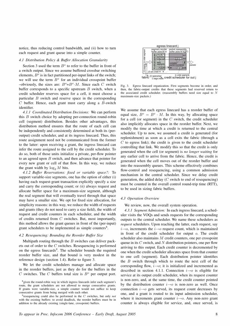
Multipath routing through the B switches can deliver pack-ets out of order to the C switches. Resequencing is performedon the egress linecards9. The scheduler bounds the requiredreorder buffer size, and that bound is very modest in thereference design (section 1.4). Refer to figure 3.
We let the credit schedulers manage and allocate spacein the reorder buffers, just as they do for the buffers in theC switches. The C buffers total size is Bo per output port.
8given the round-robin way in which ingress linecards infer each segment’sroute, the grant schedulers are not allowed to merge consecutive grants.If grants were variable-size, a simple counter would not suffice to keepconsecutive grants from being merged with each other.
9resequencing could also be performed in the C switches, but only notwith the existing buffers: to avoid deadlock, the reorder buffers must be inaddition to the already existing (single-lane, crosspoint) buffers.
����������
���������
�������� ��������
�����������
maxpkt
complete
N v
irtua
l que
ues
)
in1
in2
(1) m
issin
g, in
−ord
er s
egm
ent
egress linecard jpacket reassemblybuffer (size N*Sbuffer (size B^o)
segment reorder
segments packet boundaries
(2) ack./credit
fabric
early
(3) replenished credit scheduler for out jin−order segments
C stage credits
packets������ S
inN
3 12
Fig. 3. Egress linecard organization. First segments become in order, andthen, the fabric-output credits that these segments had reserved return tothe associated credit scheduler. (reassembly buffers need size equal to N
maximum-size packets.)
We assume that each egress linecard has a reorder buffer ofequal size, Bo = Bx · M . In this way, by allocating spacefor a cell (or segment) in the C switch, the credit scheduleralso implicitly allocates space in the reorder buffer. Next, wemodify the time at which a credit is returned to the centralscheduler. Up to now, we assumed a credit is generated (forreplenishment) as soon as a cell exits the fabric (through aC to egress link); the credit is given to the credit schedulercontrolling that link. We modify this so that the credit is onlygenerated when the cell (or segment) is no longer waiting forany earlier cell to arrive from the fabric. Hence, the credit isgenerated when the cell moves out of the reorder buffer andinto the reassembly queues. This scheme effectively combinesflow-control and resequencing, using a common admissionmechanism in the central scheduler. Since we delay creditgeneration, the added delay (C switch to end of resequencing)must be counted in the overall control round-trip time (RTT),to be used in sizing fabric buffers.
4.3 Operation Overview
We review, now, the overall system operation.4.3.1 Segment Admission: In each ingress linecard, a sched-
uler visits the VOQs and sends requests for the correspondingoutputs to the central scheduler. We name these schedulers asrequest schedulers. Upon reaching the latter, each request, sayi→o, increments the i→o request count, which is maintainedin front of the credit scheduler for output o. The creditscheduler also maintains M credit counters, one per crosspointqueue in its C switch, and N distribution pointers, one per flowarriving to this output. Each credit counter is decremented byone when the credit scheduler allocates space from that counterto one cell (segment). Each distribution pointer identifiesthe B switch through which to route the next cell of thecorresponding flow, i→o; it is initialized and incremented asdescribed in section 4.1.1. Connection i→o is eligible forservice at its output credit scheduler, when its request counteris non-zero, and, at the same time, the credit counter pointedby the distribution counter i→o is non-zero as well. Onceconnection i→o gets served, its request count decreases byone, and a grant is routed to its input admission scheduler,where it increments grant counter i→o. Any non-zero grantcounter is always eligible for service, and, once served, is
To appear in Proc. Infocom 2006 Conference – Early Draft, August 2005 8

decremented by one. When served, grant i→o is sent to itsingress linecard, to admit a new segment inside the fabric.
4.3.2 Segment Injection: In a variable-size segment system,the head segment of VOQ i→o may not be a maximum-sizesegment, when the grant arrives to this VOQ; nevertheless,this smaller segment is injected into the fabric. This meansthat the buffer spaces that have been reserved for the segmentwill not be fully utilized. This is not a problem: the reasonwhy VOQ i→o does not contain a maximum-size segment isthat this smaller segment is the only datum in the queue. Ifthe load of this flow persists, the VOQ will grow to containmultiple packets, in which case the head segment will alwaysbe a maximum-size one, thus stopping wasting buffer spacein the fabric.
The route of the candidate for injection segment is pointedby input distribution counter i→o; this counter is initializedand incremented as described in section 4.1.1. Before thesegment is injected, a sequence tag is included in its header,specifying the segment’s order among other i→o segmentsthat have been injected before it. This sequence tag is usedby the reordering circuits at egress linecard o10. The segmenthas then to compete against other “granted” segments, andwill reach its C switch subject to hop-by-hop, credit-basedbackpressure11. This backpressure is indiscriminate, but, asexplained discussed in section 3.3, it cannot introduce blockingbecause it operates on solicited packets. No backpressure isexerted from the egress linecards to the C stage.
4.4 Limiting the per-flow Outstanding Requests
Limiting by some value, say u, the number of requests thata VOQ connection may have outstanding inside the centralscheduler has the following benefits –this is controlled bythe ingress request schedulers. First, the respective request orgrant connection counter inside the central scheduler will neverwraparound (overflow) if it is at least dlog2ue-bit wide. Thereason is as follows: the “bit” requests that a VOQ connectionhas outstanding must either “reside” in its request counter(queue) or in its grant counter (queue); hence, the sum ofthese two counters will never exceed u. Moreover, this limitacts as an implicit “backpressure”, that prevents output creditschedulers from synchronizing in conflicting decisions –i.e.,granting buffers to a single, “congested” input. If some of themdo so for a while, their grants will clash in front of the inputadmission scheduler; from there, every new segment-time,only one of these grants will move out of the central scheduler,to reach its VOQ and supply its output admission schedulerwith a new request. Effectively, after a while, the synchronizedoutput (credit) schedulers will find that the “congested” inputhas no more requests for them; therefore they will be forcedto serve requests from other inputs.
10segment header also contains the information needed for the reassemblyof the packets fragments contained in it, as described in [23].
11our system also uses credit-based backpressure from the C stage to B
stage, in order to be able to safely “bypass” admissions for a few (unsolicited)segments –see section 1.5. Assuming that all the injected segments aresolicited, this backpressure will never block or halt a segment. C
cnt
cnt
cnt
cnt
cnt
cnt
cnt
cnt
cnt
cnt
cnt
cnt
cnt
cnt
cnt
cnt cnt
cnt cnt cnt
cnt
cnt
cnt
cnt cnt cntcnt
cnt cnt cntcnt
time
output idoutput idoutput id
output id
input 1 in. 2 input 1 in. 2 input 1 in. 2 input 1 in. 2
B−sw
it. idB
−swit. id
B−sw
it. id
B−sw
it. id
output idoutput idoutput id
output id
time
in1
in2in1in2
to VOQ
linecards, through A1TDM
grants/credits
time
in2
in1in2
out2out1out2
out1
in1 cnt
request counters grant counters
VOQ linecards
creditschedulers
grantinpu
t (1,
1)
(1,2
)
inpu
t (2,
1)
(2,2
)
A1 A2 A1 A2 (demux)
from
A1
to c
redi
t sch
edul
ers
schedulers
A−switches
TDM
(VO
Q) r
eque
sts
Pipelined, Single−Resource Admission Schedulers
from fabric output buffers in C1 switchTDM (replenished) credits
(mux)
(mux)
(demux)
output(2,1)
output(2,2)
output(1,2)
(1,2) input
(1,1) input
(2,1) input
(2,2) input
(1,1)output
Fig. 4. Central admission scheduler for N=4 and M=2; request-grant com-munication with VOQ linecards, and fabric-output buffer credit replenishment,from C switches, use time division multiplexing (TDM), in order to minimizemessages size, thus reducing (central) scheduler’s chip bandwidth.
5 . CENTRAL SCHEDULER IMPLEMENTATION
5.1 Central Chip Bandwidth
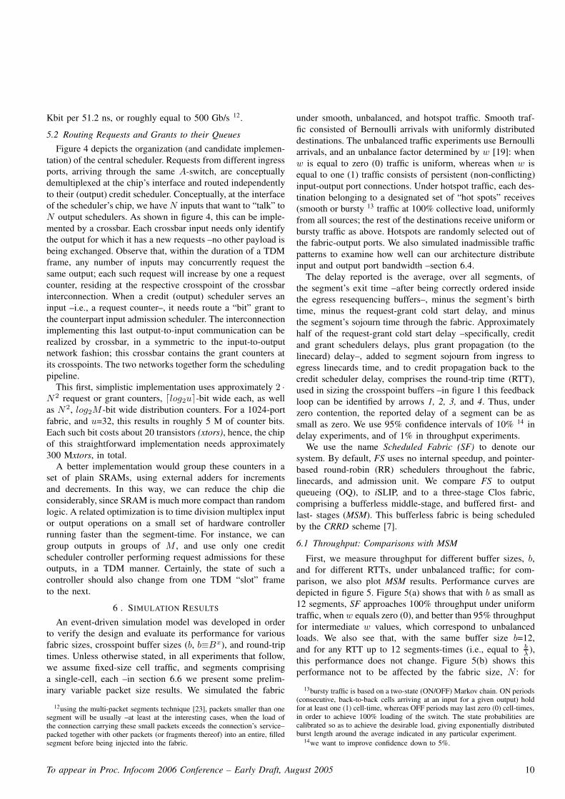
As shown in figure 4, requests issued by the ingresslinecards, first travel to the upstream A-switch, via a link con-veying one VOQ request per-segment-time; each such requestcarries along an identifier of the output port it refers to. Insidethe A switch, VOQ requests are time division multiplexed(TDM) upon a link, that transfers M (equal to the size ofeach TDM frame) VOQ requests to the scheduler per-segment-time, one from each particular input. The scheduler infers theinput port linecard of a request by its position in the TDMframe (request belt). Output grants, destined to input ports of aparticular A switch element, cross the scheduler’s boundarieson a similar TDM link (grant belt): the position (slot) of agrant in a TDM frame indicates to the A-switch the input portthat must receive the grants. The “payload” of each request orgrant notice is an identifier of the fabric-output port that thenotice goes to, or comes from; this destination identifier canbe encoded in log2N bits. Besides request-grant notices, thecentral scheduler must also receive credits from the switchesin the C stage. These credits are conveyed through a linkconnecting each C-switch with the scheduler. Each such linkconveys M credits per-segment-time, one for each associateddestination, in a similar TDM manner: the position of a creditnotice in a TDM frame “points” the fabric-output that thecredit comes from, whereas, its payload points the specificcrosspoint queue ahead of that fabric-output, generating thecredit –i.e., log2 M bits payload per TDM slot.
Using TDM multiplexing, the aggregate bandwidth of thescheduler’s chip is 2 · N · log2 N bits per-segment-time, forbeing requested from as well as granting all fabric-input ports,plus N · log2 M bits per-segment-time for being notified forbuffer credit releases from all fabric-outputs, or N ·(2·log2 N+log2 M) bits per-segment-time in total. For a 1024-port fabric,with M=32, λ=10 Gb/s, and segment size corresponding to64-Bytes, the aggregate input plus output bandwidth is 25.6
To appear in Proc. Infocom 2006 Conference – Early Draft, August 2005 9
Kbit per 51.2 ns, or roughly equal to 500 Gb/s 12.
5.2 Routing Requests and Grants to their Queues
Figure 4 depicts the organization (and candidate implemen-tation) of the central scheduler. Requests from different ingressports, arriving through the same A-switch, are conceptuallydemultiplexed at the chip’s interface and routed independentlyto their (output) credit scheduler. Conceptually, at the interfaceof the scheduler’s chip, we have N inputs that want to “talk” toN output schedulers. As shown in figure 4, this can be imple-mented by a crossbar. Each crossbar input needs only identifythe output for which it has a new requests –no other payload isbeing exchanged. Observe that, within the duration of a TDMframe, any number of inputs may concurrently request thesame output; each such request will increase by one a requestcounter, residing at the respective crosspoint of the crossbarinterconnection. When a credit (output) scheduler serves aninput –i.e., a request counter–, it needs route a “bit” grant tothe counterpart input admission scheduler. The interconnectionimplementing this last output-to-input communication can berealized by crossbar, in a symmetric to the input-to-outputnetwork fashion; this crossbar contains the grant counters atits crosspoints. The two networks together form the schedulingpipeline.
This first, simplistic implementation uses approximately 2 ·N2 request or grant counters, dlog2ue-bit wide each, as wellas N2, log2M -bit wide distribution counters. For a 1024-portfabric, and u=32, this results in roughly 5 M of counter bits.Each such bit costs about 20 transistors (xtors), hence, the chipof this straightforward implementation needs approximately300 Mxtors, in total.
A better implementation would group these counters in aset of plain SRAMs, using external adders for incrementsand decrements. In this way, we can reduce the chip dieconsiderably, since SRAM is much more compact than randomlogic. A related optimization is to time division multiplex inputor output operations on a small set of hardware controllerrunning faster than the segment-time. For instance, we cangroup outputs in groups of M , and use only one creditscheduler controller performing request admissions for theseoutputs, in a TDM manner. Certainly, the state of such acontroller should also change from one TDM “slot” frameto the next.
6 . SIMULATION RESULTS
An event-driven simulation model was developed in orderto verify the design and evaluate its performance for variousfabric sizes, crosspoint buffer sizes (b, b≡Bx), and round-triptimes. Unless otherwise stated, in all experiments that follow,we assume fixed-size cell traffic, and segments comprisinga single-cell, each –in section 6.6 we present some prelim-inary variable packet size results. We simulated the fabric
12using the multi-packet segments technique [23], packets smaller than onesegment will be usually –at least at the interesting cases, when the load ofthe connection carrying these small packets exceeds the connection’s service–packed together with other packets (or fragments thereof) into an entire, filledsegment before being injected into the fabric.
under smooth, unbalanced, and hotspot traffic. Smooth traf-fic consisted of Bernoulli arrivals with uniformly distributeddestinations. The unbalanced traffic experiments use Bernoulliarrivals, and an unbalance factor determined by w [19]: whenw is equal to zero (0) traffic is uniform, whereas when w isequal to one (1) traffic consists of persistent (non-conflicting)input-output port connections. Under hotspot traffic, each des-tination belonging to a designated set of “hot spots” receives(smooth or bursty 13 traffic at 100% collective load, uniformlyfrom all sources; the rest of the destinations receive uniform orbursty traffic as above. Hotspots are randomly selected out ofthe fabric-output ports. We also simulated inadmissible trafficpatterns to examine how well can our architecture distributeinput and output port bandwidth –section 6.4.
The delay reported is the average, over all segments, ofthe segment’s exit time –after being correctly ordered insidethe egress resequencing buffers–, minus the segment’s birthtime, minus the request-grant cold start delay, and minusthe segment’s sojourn time through the fabric. Approximatelyhalf of the request-grant cold start delay –specifically, creditand grant schedulers delays, plus grant propagation (to thelinecard) delay–, added to segment sojourn from ingress toegress linecards time, and to credit propagation back to thecredit scheduler delay, comprises the round-trip time (RTT),used in sizing the crosspoint buffers –in figure 1 this feedbackloop can be identified by arrows 1, 2, 3, and 4. Thus, underzero contention, the reported delay of a segment can be assmall as zero. We use 95% confidence intervals of 10% 14 indelay experiments, and of 1% in throughput experiments.
We use the name Scheduled Fabric (SF) to denote oursystem. By default, FS uses no internal speedup, and pointer-based round-robin (RR) schedulers throughout the fabric,linecards, and admission unit. We compare FS to outputqueueing (OQ), to iSLIP, and to a three-stage Clos fabric,comprising a bufferless middle-stage, and buffered first- andlast- stages (MSM). This bufferless fabric is being scheduledby the CRRD scheme [7].
6.1 Throughput: Comparisons with MSM
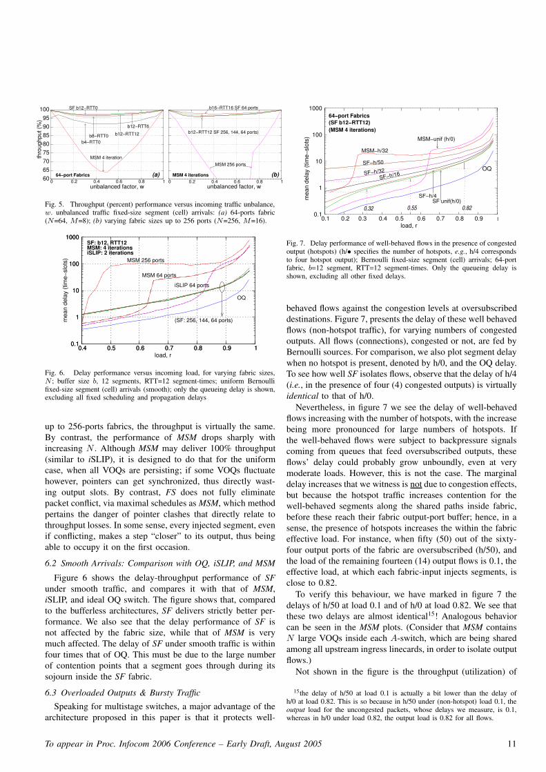
First, we measure throughput for different buffer sizes, b,and for different RTTs, under unbalanced traffic; for com-parison, we also plot MSM results. Performance curves aredepicted in figure 5. Figure 5(a) shows that with b as small as12 segments, SF approaches 100% throughput under uniformtraffic, when w equals zero (0), and better than 95% throughputfor intermediate w values, which correspond to unbalancedloads. We also see that, with the same buffer size b=12,and for any RTT up to 12 segments-times (i.e., equal to b
λ),
this performance does not change. Figure 5(b) shows thisperformance not to be affected by the fabric size, N : for
13bursty traffic is based on a two-state (ON/OFF) Markov chain. ON periods(consecutive, back-to-back cells arriving at an input for a given output) holdfor at least one (1) cell-time, whereas OFF periods may last zero (0) cell-times,in order to achieve 100% loading of the switch. The state probabilities arecalibrated so as to achieve the desirable load, giving exponentially distributedburst length around the average indicated in any particular experiment.
14we want to improve confidence down to 5%.
To appear in Proc. Infocom 2006 Conference – Early Draft, August 2005 10
(a) (b)
thro
ughp
ut (%
)
MSM 4 iteration
SF b12−RTT0
b8−RTT0b4−RTT0
b12−RTT12
b12−RTT6
64−port Fabrics MSM 4 iterations
b12−RTT12 SF 256, 144, 64 ports)
b16−RTT16 SF 64 ports
MSM 256 ports
unbalanced factor, w unbalanced factor, w 0 0.2 0.4 0.6 0.8 1
65 70
80 85 90
95 100
75
60 0 0.4 0.6 0.8 1 0.2
Fig. 5. Throughput (percent) performance versus incoming traffic unbalance,w. unbalanced traffic fixed-size segment (cell) arrivals: (a) 64-ports fabric(N=64, M=8); (b) varying fabric sizes up to 256 ports (N=256, M=16).
load, r
mea
n de
lay
(tim
e−sl
ots)
OQ
SF: b12, RTT12
(SF: 256, 144, 64 ports)
MSM 256 ports
MSM 64 ports
MSM: 4 iterationsiSLIP: 2 iterations
iSLIP 64 ports
0.1
1
10
100
1000
0.1
1
10
100
1000
0.4 0.5 0.6 0.7 0.8 0.9 1 0.4 0.5 0.6 0.7 0.8 0.9 1
Fig. 6. Delay performance versus incoming load, for varying fabric sizes,N ; buffer size b, 12 segments, RTT=12 segment-times; uniform Bernoullifixed-size segment (cell) arrivals (smooth); only the queueing delay is shown,excluding all fixed scheduling and propagation delays
up to 256-ports fabrics, the throughput is virtually the same.By contrast, the performance of MSM drops sharply withincreasing N . Although MSM may deliver 100% throughput(similar to iSLIP), it is designed to do that for the uniformcase, when all VOQs are persisting; if some VOQs fluctuatehowever, pointers can get synchronized, thus directly wast-ing output slots. By contrast, FS does not fully eliminatepacket conflict, via maximal schedules as MSM, which methodpertains the danger of pointer clashes that directly relate tothroughput losses. In some sense, every injected segment, evenif conflicting, makes a step “closer” to its output, thus beingable to occupy it on the first occasion.
6.2 Smooth Arrivals: Comparison with OQ, iSLIP, and MSM
Figure 6 shows the delay-throughput performance of SFunder smooth traffic, and compares it with that of MSM,iSLIP, and ideal OQ switch. The figure shows that, comparedto the bufferless architectures, SF delivers strictly better per-formance. We also see that the delay performance of SF isnot affected by the fabric size, while that of MSM is verymuch affected. The delay of SF under smooth traffic is withinfour times that of OQ. This must be due to the large numberof contention points that a segment goes through during itssojourn inside the SF fabric.
6.3 Overloaded Outputs & Bursty Traffic
Speaking for multistage switches, a major advantage of thearchitecture proposed in this paper is that it protects well-
load, r
mea
n de
lay
(tim
e−sl
ots)
MSM−h/32
SF−h/50
SF−h/32SF−h/16
OQ
SF−h/4
64−port Fabrics(SF b12−RTT12)(MSM 4 iterations)
SF unif(h/0)
MSM−unif (h/0)
0.1
1
10
100
1000
0.1 1 0.4 0.6 0.7 0.9 0.5 0.3 0.2 0.8
0.55 0.82 0.32
Fig. 7. Delay performance of well-behaved flows in the presence of congestedoutput (hotspots) (h/• specifies the number of hotspots, e.g., h/4 correspondsto four hotspot output); Bernoulli fixed-size segment (cell) arrivals; 64-portfabric, b=12 segment, RTT=12 segment-times. Only the queueing delay isshown, excluding all other fixed delays.
behaved flows against the congestion levels at oversubscribeddestinations. Figure 7, presents the delay of these well behavedflows (non-hotspot traffic), for varying numbers of congestedoutputs. All flows (connections), congested or not, are fed byBernoulli sources. For comparison, we also plot segment delaywhen no hotspot is present, denoted by h/0, and the OQ delay.To see how well SF isolates flows, observe that the delay of h/4(i.e., in the presence of four (4) congested outputs) is virtuallyidentical to that of h/0.
Nevertheless, in figure 7 we see the delay of well-behavedflows increasing with the number of hotspots, with the increasebeing more pronounced for large numbers of hotspots. Ifthe well-behaved flows were subject to backpressure signalscoming from queues that feed oversubscribed outputs, theseflows’ delay could probably grow unboundly, even at verymoderate loads. However, this is not the case. The marginaldelay increases that we witness is not due to congestion effects,but because the hotspot traffic increases contention for thewell-behaved segments along the shared paths inside fabric,before these reach their fabric output-port buffer; hence, in asense, the presence of hotspots increases the within the fabriceffective load. For instance, when fifty (50) out of the sixty-four output ports of the fabric are oversubscribed (h/50), andthe load of the remaining fourteen (14) output flows is 0.1, theeffective load, at which each fabric-input injects segments, isclose to 0.82.
To verify this behaviour, we have marked in figure 7 thedelays of h/50 at load 0.1 and of h/0 at load 0.82. We see thatthese two delays are almost identical15! Analogous behaviorcan be seen in the MSM plots. (Consider that MSM containsN large VOQs inside each A-switch, which are being sharedamong all upstream ingress linecards, in order to isolate outputflows.)
Not shown in the figure is the throughput (utilization) of
15the delay of h/50 at load 0.1 is actually a bit lower than the delay ofh/0 at load 0.82. This is so because in h/50 under (non-hotspot) load 0.1, theoutput load for the uncongested packets, whose delays we measure, is 0.1,whereas in h/0 under load 0.82, the output load is 0.82 for all flows.
To appear in Proc. Infocom 2006 Conference – Early Draft, August 2005 11
mea
n de
lay
(tim
e−sl
ots)
load, r
OQ
OQ
(SF b12−RTT12)256−port Fabrics
bursts36
bursts12 SF unif(h/0), h/4, h/16
SF unif(h/0), h/4, h/16
0.1 0.2 0.3 0.4 0.5 0.6 0.7 0.8 0.9 1 1
4
16
64
256
1024
4096
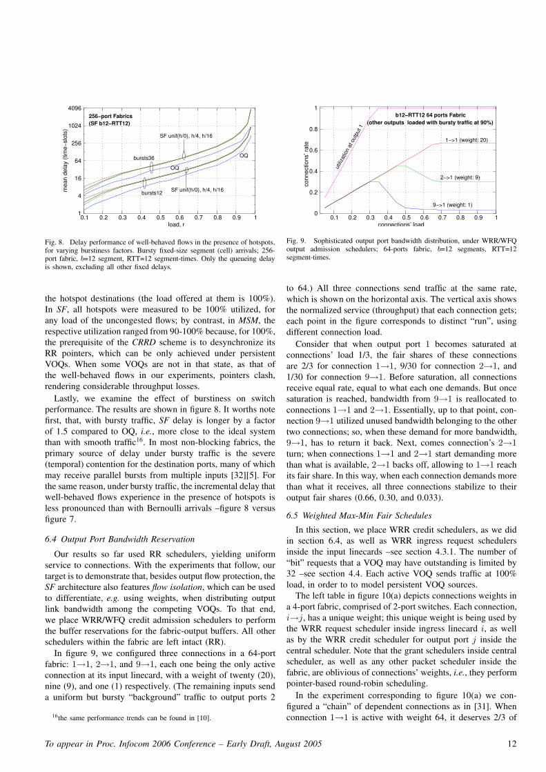
Fig. 8. Delay performance of well-behaved flows in the presence of hotspots,for varying burstiness factors. Bursty fixed-size segment (cell) arrivals; 256-port fabric, b=12 segment, RTT=12 segment-times. Only the queueing delayis shown, excluding all other fixed delays.
the hotspot destinations (the load offered at them is 100%).In SF, all hotspots were measured to be 100% utilized, forany load of the uncongested flows; by contrast, in MSM, therespective utilization ranged from 90-100% because, for 100%,the prerequisite of the CRRD scheme is to desynchronize itsRR pointers, which can be only achieved under persistentVOQs. When some VOQs are not in that state, as that ofthe well-behaved flows in our experiments, pointers clash,rendering considerable throughput losses.
Lastly, we examine the effect of burstiness on switchperformance. The results are shown in figure 8. It worths notefirst, that, with bursty traffic, SF delay is longer by a factorof 1.5 compared to OQ, i.e., more close to the ideal systemthan with smooth traffic16. In most non-blocking fabrics, theprimary source of delay under bursty traffic is the severe(temporal) contention for the destination ports, many of whichmay receive parallel bursts from multiple inputs [32][5]. Forthe same reason, under bursty traffic, the incremental delay thatwell-behaved flows experience in the presence of hotspots isless pronounced than with Bernoulli arrivals –figure 8 versusfigure 7.
6.4 Output Port Bandwidth Reservation
Our results so far used RR schedulers, yielding uniformservice to connections. With the experiments that follow, ourtarget is to demonstrate that, besides output flow protection, theSF architecture also features flow isolation, which can be usedto differentiate, e.g. using weights, when distributing outputlink bandwidth among the competing VOQs. To that end,we place WRR/WFQ credit admission schedulers to performthe buffer reservations for the fabric-output buffers. All otherschedulers within the fabric are left intact (RR).
In figure 9, we configured three connections in a 64-portfabric: 1→1, 2→1, and 9→1, each one being the only activeconnection at its input linecard, with a weight of twenty (20),nine (9), and one (1) respectively. (The remaining inputs senda uniform but bursty “background” traffic to output ports 2
16the same performance trends can be found in [10].
utiliz
atio
n at
out
put 1
9−>1 (weight: 1)
2−>1 (weight: 9)
1−>1 (weight: 20)
connections’ load
(other outputs loaded with bursty traffic at 90%)
conn
ectio
ns’ r
ate
b12−RTT12 64 ports Fabric
0.1 0.2 0.3 0.4 0.5 0.6 0.7 0.8 0.9 1 0
1
0.2
0.4
0.6
0.8
Fig. 9. Sophisticated output port bandwidth distribution, under WRR/WFQoutput admission schedulers; 64-ports fabric, b=12 segments, RTT=12segment-times.
to 64.) All three connections send traffic at the same rate,which is shown on the horizontal axis. The vertical axis showsthe normalized service (throughput) that each connection gets;each point in the figure corresponds to distinct “run”, usingdifferent connection load.
Consider that when output port 1 becomes saturated atconnections’ load 1/3, the fair shares of these connectionsare 2/3 for connection 1→1, 9/30 for connection 2→1, and1/30 for connection 9→1. Before saturation, all connectionsreceive equal rate, equal to what each one demands. But oncesaturation is reached, bandwidth from 9→1 is reallocated toconnections 1→1 and 2→1. Essentially, up to that point, con-nection 9→1 utilized unused bandwidth belonging to the othertwo connections; so, when these demand for more bandwidth,9→1, has to return it back. Next, comes connection’s 2→1turn; when connections 1→1 and 2→1 start demanding morethan what is available, 2→1 backs off, allowing to 1→1 reachits fair share. In this way, when each connection demands morethan what it receives, all three connections stabilize to theiroutput fair shares (0.66, 0.30, and 0.033).
6.5 Weighted Max-Min Fair Schedules
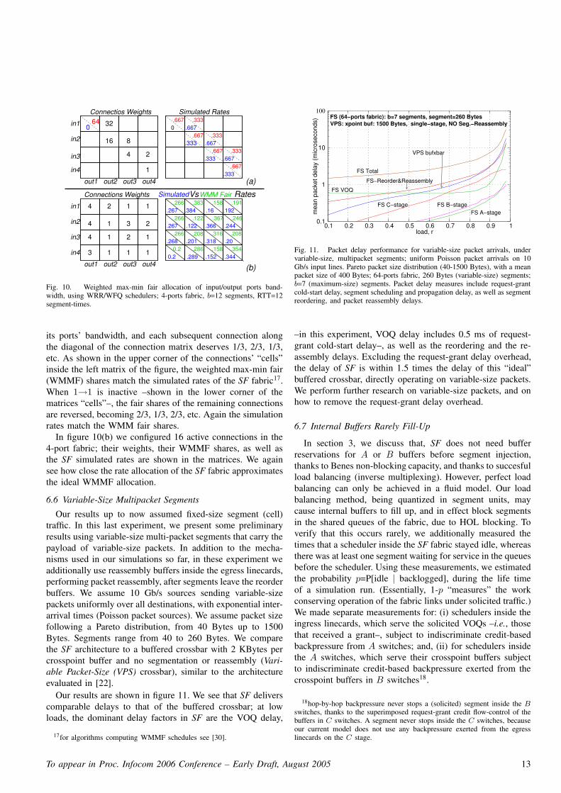
In this section, we place WRR credit schedulers, as we didin section 6.4, as well as WRR ingress request schedulersinside the input linecards –see section 4.3.1. The number of“bit” requests that a VOQ may have outstanding is limited by32 –see section 4.4. Each active VOQ sends traffic at 100%load, in order to to model persistent VOQ sources.
The left table in figure 10(a) depicts connections weights ina 4-port fabric, comprised of 2-port switches. Each connection,i→j, has a unique weight; this unique weight is being used bythe WRR request scheduler inside ingress linecard i, as wellas by the WRR credit scheduler for output port j inside thecentral scheduler. Note that the grant schedulers inside centralscheduler, as well as any other packet scheduler inside thefabric, are oblivious of connections’ weights, i.e., they performpointer-based round-robin scheduling.
In the experiment corresponding to figure 10(a) we con-figured a “chain” of dependent connections as in [31]. Whenconnection 1→1 is active with weight 64, it deserves 2/3 of
To appear in Proc. Infocom 2006 Conference – Early Draft, August 2005 12
1
out1 out2 out3 out4
4
4
4
1
3
2 1
3
2
2
1
1
1
1 1
in1
in2
in3
in4
Connections Weights
(a)
(b)
32
16 8
4 2
1
Connectios Weights
out1 out2 out3 out4
640
Simulated Rates
in1
in2
in3
in4
0.667 .333
.667
.667.667
.333
.266.267 .384
.383
.316
.2860.2
.266
.122.266
.158 .191
.246
.208
.354.158.268
0.2
.267
.201
.667
.333
.333
.667
.333
.333.667
.367
.208
.192
.20
.289
.318
.366
.16
.244.122
RatesWMM FairVsSimulated
.344 .152
Fig. 10. Weighted max-min fair allocation of input/output ports band-width, using WRR/WFQ schedulers; 4-ports fabric, b=12 segments, RTT=12segment-times.
its ports’ bandwidth, and each subsequent connection alongthe diagonal of the connection matrix deserves 1/3, 2/3, 1/3,etc. As shown in the upper corner of the connections’ “cells”inside the left matrix of the figure, the weighted max-min fair(WMMF) shares match the simulated rates of the SF fabric17.When 1→1 is inactive –shown in the lower corner of thematrices “cells”–, the fair shares of the remaining connectionsare reversed, becoming 2/3, 1/3, 2/3, etc. Again the simulationrates match the WMM fair shares.
In figure 10(b) we configured 16 active connections in the4-port fabric; their weights, their WMMF shares, as well asthe SF simulated rates are shown in the matrices. We againsee how close the rate allocation of the SF fabric approximatesthe ideal WMMF allocation.
6.6 Variable-Size Multipacket Segments
Our results up to now assumed fixed-size segment (cell)traffic. In this last experiment, we present some preliminaryresults using variable-size multi-packet segments that carry thepayload of variable-size packets. In addition to the mecha-nisms used in our simulations so far, in these experiment weadditionally use reassembly buffers inside the egress linecards,performing packet reassembly, after segments leave the reorderbuffers. We assume 10 Gb/s sources sending variable-sizepackets uniformly over all destinations, with exponential inter-arrival times (Poisson packet sources). We assume packet sizefollowing a Pareto distribution, from 40 Bytes up to 1500Bytes. Segments range from 40 to 260 Bytes. We comparethe SF architecture to a buffered crossbar with 2 KBytes percrosspoint buffer and no segmentation or reassembly (Vari-able Packet-Size (VPS) crossbar), similar to the architectureevaluated in [22].
Our results are shown in figure 11. We see that SF deliverscomparable delays to that of the buffered crossbar; at lowloads, the dominant delay factors in SF are the VOQ delay,
17for algorithms computing WMMF schedules see [30].
load, r
FS VOQ
FS−Reorder&Reassembly
FS Total
FS B−stageFS A−stage
FS C−stage
VPS bufxbar
VPS: xpoint buf: 1500 Bytes, single−stage, NO Seg.−ReassemblyFS (64−ports fabric): b=7 segments, segment=260 Bytes
mea
n pa
cket
del
ay (m
icro
seco
nds)
0.1
1
10
0.3 0.4 0.5 0.6 0.7 0.8 0.9 1 0.1
100
0.2
Fig. 11. Packet delay performance for variable-size packet arrivals, undervariable-size, multipacket segments; uniform Poisson packet arrivals on 10Gb/s input lines. Pareto packet size distribution (40-1500 Bytes), with a meanpacket size of 400 Bytes; 64-ports fabric, 260 Bytes (variable-size) segments;b=7 (maximum-size) segments. Packet delay measures include request-grantcold-start delay, segment scheduling and propagation delay, as well as segmentreordering, and packet reassembly delays.
–in this experiment, VOQ delay includes 0.5 ms of request-grant cold-start delay–, as well as the reordering and the re-assembly delays. Excluding the request-grant delay overhead,the delay of SF is within 1.5 times the delay of this “ideal”buffered crossbar, directly operating on variable-size packets.We perform further research on variable-size packets, and onhow to remove the request-grant delay overhead.
6.7 Internal Buffers Rarely Fill-Up
In section 3, we discuss that, SF does not need bufferreservations for A or B buffers before segment injection,thanks to Benes non-blocking capacity, and thanks to succesfulload balancing (inverse multiplexing). However, perfect loadbalancing can only be achieved in a fluid model. Our loadbalancing method, being quantized in segment units, maycause internal buffers to fill up, and in effect block segmentsin the shared queues of the fabric, due to HOL blocking. Toverify that this occurs rarely, we additionally measured thetimes that a scheduler inside the SF fabric stayed idle, whereasthere was at least one segment waiting for service in the queuesbefore the scheduler. Using these measurements, we estimatedthe probability p=P[idle | backlogged], during the life timeof a simulation run. (Essentially, 1-p “measures” the workconserving operation of the fabric links under solicited traffic.)We made separate measurements for: (i) schedulers inside theingress linecards, which serve the solicited VOQs –i.e., thosethat received a grant–, subject to indiscriminate credit-basedbackpressure from A switches; and, (ii) for schedulers insidethe A switches, which serve their crosspoint buffers subjectto indiscriminate credit-based backpressure exerted from thecrosspoint buffers in B switches18.
18hop-by-hop backpressure never stops a (solicited) segment inside the B
switches, thanks to the superimposed request-grant credit flow-control of thebuffers in C switches. A segment never stops inside the C switches, becauseour current model does not use any backpressure exerted from the egresslinecards on the C stage.
To appear in Proc. Infocom 2006 Conference – Early Draft, August 2005 13

Our results showed that redundant blocking appears morefrequently on the links connecting VOQ linecards with Aswitches, than on the links connecting A with B switches.But, for both cases, results showed p probabilities to be verysmall. As expected, p probabilities are dependent on buffersize B –p decreases with increasing B–, and also dependenton load, but rather inelastic to traffic type. The dependence onbuffer size B becomes marginal for B ≥ 10-12 segments: pdrops to zero under loads smaller than 80%, reaching 0.0004at 98% load (3-4 redundant stops in every 104 samples); evenat full 100% load, p stays close to 0.004. We found that theseresults do not change with bursty traffic or overloaded outputs.Ending this section, we need to comment that the blockingprobability measured is an average extracted from long-lastingsimulations. In the very short term, p probabilities may risedue to distribution pointers clashing.
7 . CONCLUSIONS & FUTURE WORK
We proposed and evaluated a novel, effective, and realisticscheduling architecture for non-blocking switching fabrics. Itrelies on multiple, independent, single-resource schedulers,operating in a pipeline. It unifies the ideas of central anddistributed scheduling, and it demonstrates the latency - bufferspace tradeoff. It provides excellent performance at realisticcost.
Work in progress includes completing our study of variable-size segment performance, designing schemes to route back-pressure and control signals more efficiently, and simulatingvarious protocols that eliminate the request-grant delay underlight load. These will have been completed in the final versionof the paper.
Other future work includes a careful comparison against theRECN protocol, a study of other scheduling disciplines besidesRR or WFQ/WRR (as that proposed in [13] for networks withfinite buffers), and a study of multicast capabilities.
8 . ACKNOWLEDGMENTS
This work has been supported by an IBM Ph.D. Fellow-ship. The authors would especially like to thank GeorgiosSapuntzis for his stimulating work on Benes networks, aswell as Kostas Harteros and Dionisis Pnevmatikatos for theirvaluable contribution in implementation issues. Among others,the authors especially thank Paraskevi Fragopoulou, IoannisPapaefstathiou, Georgios Georgakopoulos, Vassilios Siris, andGeorgios Passas for helpful discussions.
REFERENCES
[1] V. Benes: “Optimal Rearrangeable Multistage Connecting Networks”,Bell Systems Technical Journal, vol. 43, no. 7, pp. 1641-1656, July 1964.
[2] M. Katevenis, “Fast switching and Fair Control of Congested Flow inBroad-Band Networks”, IEEE Journal on Selected Areas in Communi-cation, vol. 5, no. 8, pp. 1315-1326, Oct. 1987.
[3] M. J. Karol, M. G. Hluchyj, and S. P. Morgan, “Input Versus OutputQueueing on a Space-Division Packet Switch”, IEEE Trans. Commun.,vol. COM35, no.12, Dec. 1987.
[4] T. Anderson, S. Owicki, J. Saxe, C. Thacker: “High-Speed SwitchScheduling for Local-Area Networks”, ACM Trans. on Computer Sys-tems, vol. 11, no. 4, Nov. 1993, pp. 319-352.
[5] Nick McKeown: “The iSLIP Scheduling Algorithm for Input-QueuedSwitches” IEEE/ACM Trans. on Networking, vol. 7, no. 2, April 1999.
[6] F. M. Chiussi, J. G. Kneuer, and V. P. Kumar: “The ATLANTAarchitecture and chipset”, IEEE Commun. Mag., December 1997, pp.44-53.
[7] Eiji Oki, Zhigang Jing, Roberto Rojas-Cessa, H.J. Chao: “ConcurrentRound-Robin-Based Dispatching Schemes for Clos-Network Switches”,IEEE/ACM Trans. on Networking vol. 10, no. 2 December 2002.
[8] Xin Li, Zhen Zhou, and Mounir Hamdi: “Space-Memory-MemoryArchitecture for Clos-Network Packet Switches”, Proc. IEEE ICC’05,Seoul, Korea, 16-20 May 2005, CR-ROM paper ID ”09GC08-4”, 6pages.
[9] Stefano Gianatti and Achille Pattavina: “Performance Analysis of ATMBanyan Networks with Shared Queueing –Part I: Random OfferedTraffic”, IEE Trans. Commun., vol.2, no. 4, pp. 398-410, August 1994.
[10] G. Sapountzis, M. Katevenis: “Benes Switching Fabrics with O(N)-Complexity Internal Backpressure”, IEEE Communications Magazine,vol. 43, no. 1, January 2005, pp. 88-94.
[11] N. Chrysos, Manolis Katevenis: “Scheduling in Switches with SmallInternal Buffers”, to appear in Globecom’05;http://archvlsi.ics.forth.gr/bpbenes
[12] S. Iyer, N. McKeown: “Making Parallel Packet Switches Practical”,IEEE INFOCOM Conf., Alaska, USA, March 2001.
[13] Paolo Giaccone, Emilio Leonardi, Devavrat Shah: “On the MaximalThroughput of Networks with Finite Buffers and its Application toBuffered Crossbars”, IEEE INFOCOM Conf., Miami USA, March 2005.
[14] S. Iyer, N. McKeown: “Analysis of the parallel packet switch architec-ture”, IEEE/ACM Trans. on Networking, 2003, 314-324.
[15] D. Khotimsky, S. Krishnan: “Stability analysis of a parallel packet switchwith bufferless input demultiplexors”, Proc. IEEE ICC, 2001 100-111.
[16] Prashanth Pappu, Jyoti Parwatikar, Jonathan Turner and Ken Wong:“Distributed Queueing in Scalable High Performance Routers”, Proc.IEEE Infocom, March 2003.
[17] Prashanth Pappu, Jonathan Turner and Ken Wong: “Work-ConservingDistributed Schedulers for Terabit Routers”, Proc. of SIGCOMM,September 2004.
[18] D. Stephens, Hui Zhang: “Implementing Distributed Packet Fair Queue-ing in a Scalable Switch Architecture”, IEEE INFOCOM’98 Conference,San Francisco, CA, Mar. 1998, pp. 282-290.
[19] R. Rojas-Cessa, E. Oki, H. Jonathan Chao: “CIXOB-k: Combined Input-Crosspoint-Output Buffered Switch”, Proc. IEEE GLOBECOM’01, vol.4, pp. 2654-2660.
[20] N. Chrysos, M. Katevenis: “Weighted Fairness in Buffered Cross-bar Scheduling”, Proc. IEEE HPSR’03, Torino, Italy, pp. 17-22;http://archvlsi.ics.forth.gr/bufxbar/
[21] F. Abel, C. Minkenberg, R. Luijten, M. Gusat, I. Iliadis: “A Four-Terabit Packet Switch Supporting Long Round-Trip Times”, IEEE MicroMagazine, vol. 23, no. 1, Jan./Feb. 2003, pp. 10-24.
[22] Manolis Katevenis, Giorgos Passas, Dimitris Simos, Ioannis Papaefs-tathiou, Nikos Chrysos: “Variable Packet Size Buffered Crossbar (CICQ)Switches”, Proc. IEEE ICC’04, Paris, France, vol. 2, pp. 1090-1096;http://archvlsi.ics.forth.gr/bufxbar
[23] M. Katevenis, G. Passas: “Variable-Size Multipacket Segments inBuffered Crossbar (CICQ) Architectures”, Proc. IEEE Int. Conf. onCommunications (ICC 2005), Seoul, Korea, 16-20 May 2005, paper ID”09GC08-4”; http://archvlsi.ics.forth.gr/bufxbar/
[24] G. Kornaros, e.a.: “ATLAS I: Implementing a Single-Chip ATM Switchwith Backpressure”, IEEE Micro, vol. 19, no. 1, Jan/Feb. 1999, pp. 30-41.
[25] M. Katevenis, D. Serpanos, E. Spyridakis: “Credit-Flow-ControlledATM for MP Interconnection: the ATLAS I Single-Chip ATM Switch”,Proc. 4th IEEE Int. Symp. High-Perf. Computer Arch. (HPCA-4), LasVegas, NV USA, Feb. 1998, pp. 47-56; http://archvlsi.ics.forth.gr/atlasI/
[26] J. Duato, I. Johnson, J. Flich, F. Naven, P. Garcia, T. Nachiondo: “ANew Scalable and Cost-Effective Congestion Management Strategy forLossless Multistage Interconnection Networks”, Proc. 11th IEEE Int.Symp. High-Perf. Computer Arch. (HPCA-11), San Francisco, CA USA,Feb. 2005, pp. 108-119.
[27] W. Kabacinski, C-T. Lea, G. Xue - Guest Editors: 50th Anniversaryof Clos networks –a collection of 5 papers, IEEE CommunicationsMagazine, vol. 41, no. 10, Oct. 2003, pp. 26-63.
[28] L. Valiant, G. Brebner: “Universal Schemes for Parallel Communication”Proc. 13th ACM Symp. on Theory of Computing (STOC), Milwaukee,WI USA, May 1981, pp. 263-277.
To appear in Proc. Infocom 2006 Conference – Early Draft, August 2005 14
[29] F. Chiussi, D. Khotimsky, S. Krishnan: “Generalized Inverse Multi-plexing for Switched ATM Connections” Proc. IEEE GLOBECOMConference, Australia, Nov. 1998, pp. 3134-3140.
[30] E. Hahne: “Round-Robin Scheduling for Max-Min Fairness in DataNetworks”, IEEE Journal on Selected Areas in Communications, vol.9, no. 7, September 1991.
[31] N. Chrysos, M. Katevenis: “Transient Behavior of a Buffered CrossbarConverging to Weighted Max-Min Fairness”, Inst. of Computer Science,FORTH, August 2002, 13 pages; http://archvlsi.ics.forth.gr/bufxbar/
[32] S. Q. Li: “Performance of a Nonblocking Space-Division Packet Switchwith Correlated Input Traffic”, IEEE Trans. on Communications , vol.40, no. 1, Jan. 1992, pp. 97-107.
To appear in Proc. Infocom 2006 Conference – Early Draft, August 2005 15