scheffler dish
TRANSCRIPT

Scheffler Dishbased Solar System
Operations & Maintenance Manual
lR;eso t;rsMNRE
November, 2014
UNDP-GEF Project on Concentrated Solar HeatMinistry of New & Renewable Energy
Government of India
MSA RENEWTECHF O U N D AT I O N
Prepared By:

1
Contents
Acknowledgement 3
About This Manual 5
1.0 General Description 6
2.0 How a Scheffler Dish System Works 7
3.0 Specifications 83.1 Interpreting System Specifications 83.2 Interpreting Subsystem Specifications 83.3 Interpreting Component Specifications 103.4 P&I Diagram 14
4.0 Description of Reflecting, Receiving and Tracking Mechanisms 16
5.0 Circulation System - Steam vs Thermic Fluid 19
6.0 Safety Information 206.1 General Safety Risks and Precautions 206.2 Use of Personal Protective Equipment (PPE) 216.3 Precautions During Operation and Maintenance 216.4 Chemicals used and health related precautions 226.5 IBR (Indian Boiler Regulations) Safety Regulations 22
7.0 System Operation 237.1 Startup Sequence 237.2 Start-up Precautions 247.3 Operation 247.4 Monitoring and Control 257.5 Exceptions and Backup 257.6 Shutdown Sequence 257.7 Shutdown Precautions 26
8.0 Maintenance 268.1 Predictive and Preventive Maintenance 268.2 Consumable Replacement 288.3 Maintenance Do’s and Don’ts 28
9.0 Troubleshooting 29
Appendix 1: Sample Bill of Materials 34
Appendix 2: Operation Logbooks 36
Appendix 3: Focus Setting 38
Appendix 4: Maintenance 42
Standard Task Procedure 01: Cleaning of Y-Strainer 43Standard Task Procedure 02 : Removing Insulation for Repair 45Standard Task Procedure 03 : Daily and Seasonal Adjustment of Scheffler Dishes 47Standard Task Procedure 04 : Calibration of Pressure Reducing Valve 50Standard Task Procedure 05 : Calibration of Temperature Transmitter 51Standard Task Procedure 06 : Descaling of Pipelines 53

2

3
Acknowledgement
This document is the result of active mentorship, support and inputs from the following individuals:
Dr. S. K. Singh, MNRE
Dr. A. K. Singhal, MNRE-UNDP Project Management Unit
Dr. R. P. Goswami, MNRE
Shri Pankaj Kumar, MNRE-UNDP Project Management Unit
Dr. Kiran Deshpande, Innovation Head at Thermax Ltd.
Dr. Deepak Gadhia, Founder of Gadhia Solar Ltd. and Director of MSA Renew Tech Foundation
Shri Sandeep Mahore, Senior Project Executive at Thermax Ltd.
Shri Sunil Sangwan, Engineer at Thermax Ltd.
Shri Kaliash, Technician at Solar Energy Center, Gurgaon
The manual received significant input from Thermax Ltd. on a pro-bono basis.

4

5
About This Manual
This document describes parabolic dish solar concentrators, also called Scheffler dishes and the procedures needed to operate and maintain them successfully. The document is intended primarily for instructors, supervisors and engineers to train the site level technicians.
The document maintains a focus on the practical day-to-day tasks of operating a parabolic trough system. The design of the system and the engineering considerations behind its operation are not covered unless they have a direct bearing on operational decisions.
Please note that the manual presents generalized information that is not specific to any specific manufacturer. It prepares the student to quickly learn the specifics of a particular system during on boarding and deployment on an installed site.

6
1.0 General Description
Heat from sun’s rays can be harnessed to provide heat to a variety of applications. But in general, sun’s rays are too diffuse to be of direct use in these applications. So solar concentrators are used to collect and concentrate sun’s rays to heat up a working fluid to the required temperature.
An arrangement of Scheffler dishes is shown in Figure 1 below.
Some of the common application where Scheffler steam systems are used are:
1. Boiler feed water preheating
2. Washing in laundries
3. Oil heating for cooking or industrial applications
4. Milk pasteurization
5. Steam cooking
Figure 1: Scheffler Steam Generation Dishes

7
2.0 How a Scheffler Dish System Works
A Scheffler reflector is a small lateral section of a paraboloid (Figure 2), which concentrates sun’s radiation over a fixed focus.
Figure 2: Solar Scheffler Dish Concentrator
The Scheffler dish system works on the following principles:
1. The parabolic reflective dish turns about north-south axis parallel to earth’s axis, tracking the sun’s movement from morning (East) to evening (West), maintaining gravitational equilibrium of the dish
2. The parabolic reflector also performs change in inclination angle while staying directed to sun, in order to obtain sharp focal point
3. Focus lies at the axis of rotation. It remains at a fixed position, where concentrated heat is captured and transferred to water through the receiver to generate hot water or high pres-sure steam
4. Water from header pipe passes to receiver (thermosyphon principle). At the receiver, the hot water or steam generated water and collected in the header pipe flows to the end use application.

8
3.0 Specifications
3.1 Interpreting System Specifications
A system to generate heat from Scheffler dishes, consists of a number of sub-systems and components. However, it is easy to see what the entire system does by specifying just a few basic parameters. Table 1 below shows the specification of a particular Scheffler system as an example. Please note that the format for technical specifications will vary by manufacturer.
Table 1. System Specification
Sr. no
System Description Example Values Description
1 Nominal Rating (per dish)
2.5 kWh (10 m2 Dish)5.5 kWh (16 m2 Dish) (approx.)
The heat energy outputreceived on a clear sunny day
2 Basic Module Description
Scheffler Dish concentrating heat on receiver
The basic unit for collecting, concentrating and capturing sun’s heat
3 Working Fluid Water/ Thermic Fluid Oil The fluid through which heat from the sun is transferred to the end application
4 System Temperature Range
150°C-260°C The temperature range in which the working fluid operates
5 End use Application Industrial process steam used for Cooking/laundry/vapor absorption for cooling/ milk pasteurization
The final use to which system is put
3.2 Interpreting Subsystem Specifications
Figure 3. Subsystems of a CST System
As seen in Figure 3, the entire system can be thought of as made up of subsystems each performing a core function.

9
The receiving subsystem collects solar radiation in the solar field from parabola shaped reflecting collectors and transfers it to working fluid such as water or oil.
The tracking subsystem acts as a support to the receiving subsystem. It maximizes the solar energy captured by moving solar collectors towards the sun for complete day. Some tracking systems also track the sun as it changes its position during the seasons.
The circulation subsystem carries fluid and transfers the heat received by it to the end use application. Fluid has to circulate in the system at a certain rate to quickly and efficiently transfer the received heat from solar field to end use application. Circulation subsystem has a number of components such as pipes, pumps and valves to control fluid flow and temperature.
The thermal storage subsystem is a part of the circulation system. It extracts heat from the circulating fluid when the temperature becomes too high. When the temperature is too low, it supplies stored heat to the fluid.
Finally, the control mechanism is the brain behind tracking and circulation system. It sends signals to these systems to control the tracking of the receiver and the pressure and flow rate of the circulating fluid.
The table below shows a sample specification that describes each subsystem in more detail. The values provided are examples only. Please note that the format for technical specifications will vary by manufacturer.
Table 2. Subsystem Specification (Case Study of a Scheffler Steam Cooking System)
Sr. no
Subsystem Description Example Values Description
1 Collector System Collects and reflects Sun’s heat at a fixed focus point
1.1 Scheffler Dish Reflecting Surface
Mirrors with protective coating at back
73 Scheffler Dishes of 16 m2 each concentrate sun’s rays on 73 receivers (heat exchangers) placed in the focus of each dish
Water from header pipe placed above the receiver, which enters the receiver and gets converted to steam due to high temperature achieved due to high solar concentration. The steam collected in the header pipe is piped to the kitchen for cooking
Number of Dishes 73Total collector area 1168 m2
System energy capacity (8 hours)
27,62,320 kCal/Day
Steam Generation capacity
365 Kg/hour peak
Mounting Location Roof Top MountingFocus Stationary Focus
1.2 Receiving System Tank Receiver painted black
Collects the heat and converts it to steam/hot oil
Heating Media Water converted to steamNominal Temperature 180°C (steam at 10 Kg/cm2
pressure)

10
Sr. no
Subsystem Description Example Values Description
2 Tracking MechanismMounting Structure Elliptical Parabolic Dish mounted on a
stand rotating parallel to Earth’s Polar Axis
Tracking Dual Axis Tracking
East-West (Daily Tracking)Automatic
North-South (Seasonal) Manual
The direction in which the solar collectors move to track sun’s rays on receiver
Drive mechanism DC wiper motor Scheffler dishes are inter-connected with wire rope going over gear-box which is driven by DC motor (in clockwise/ anti-clockwise direction)
3 Circulation SubsystemFluid composition RO/DM water converted to
steamOperating pressure Pressure Reducing Valve
reduces system pressure to <1Kg/cm2 at cooking vessel level
Operating temperature
180°C< 105 °C
Pressure protection Safety Relief Valve at Header Pipe and Jacketed Cooking Vessel to vent excess steam to ensure that the system pressure doesn’t go above system design pressure
3.3 Interpreting Component Specifications
The key components in any Scheffler system are described below.
Scheffler Dishes as shown in Figure 4 are a class of parabolic shaped reflector, made up of solar grade reflecting mirrors. An illustrative example of the technical specification of a dish is provided below. Please note that the method of specifying the dish will vary by manufacturer.

11
Table 3. Specification of a 16 m2 Scheffler Dish:
Sr. No. Module Description Rating
1 Surface Area of Collector 16 m2
2 Aperture Area of Collector 11.65 m2(Average)3 Dimension & Shape Parabolic4 Reflectivity 92 %5 Thermal output Capacity 5.5 KW6 Thermal Efficiency 42 % (approx.)7 Footprint Ground Area Required for
Single Dish Stand and Receiver35 m2
Scheffler Dish Concentrator Receiver at fixed focus of Scheffler Dish
Figure 4: Scheffler Dish Concentrator and Receiver
Receiver
• As shown in Figure 5, is placed at the focus of the Dish, which absorbs concentrated sunlight to heat up water to generate steam
• Receiver works on thermosyphon principle, in which cold water sinks down from header to receiver, and hot water/steam comes up (lower relative density) and is collected back in header pipe for storage
Header Pipe
• Storage tank contains water in the lower half and steam in upper half
• Works as a buffer system, i.e. it collects and stores steam generated by Scheffler system, which can be utilized as per requirement

12
Table 4. Component Specifications
Sr. No. Component Description Specification and
UnitsTracking System
1 Gearbox &cycle
Gives torque to move rotary support with accurate movement
Make:Gear Ratio:
2 Wiper Motor Gives motion to drive wiper motor
Make:Model:RPM:
Control System
3 Timer Controls tracking of the dish
Input: From HMI (Human Machine Interface)
4 Solar radiation sensor
To monitor and log solar radiation received, for monitoring system’s efficiency
ThermopileRange: 0 to ___ W/ sq. meter Output: 0 to ___mV
5 Wind speed sensor
To detect storms, when the wind velocity exceeds a certain speed, parabolic trough should go to the stowing position (0 degree)
3 cup anemometerWind Range: 0 to ___ meters/sec
Circulation System
6 Hot water pump
Hot water circulating pump
Make:Voltage: ___ Volts Current: ___ Amps Speed: ___ RPMHead: _ bar Capacity: ___ litres of water per secondMax Water Temp: ___°C
13
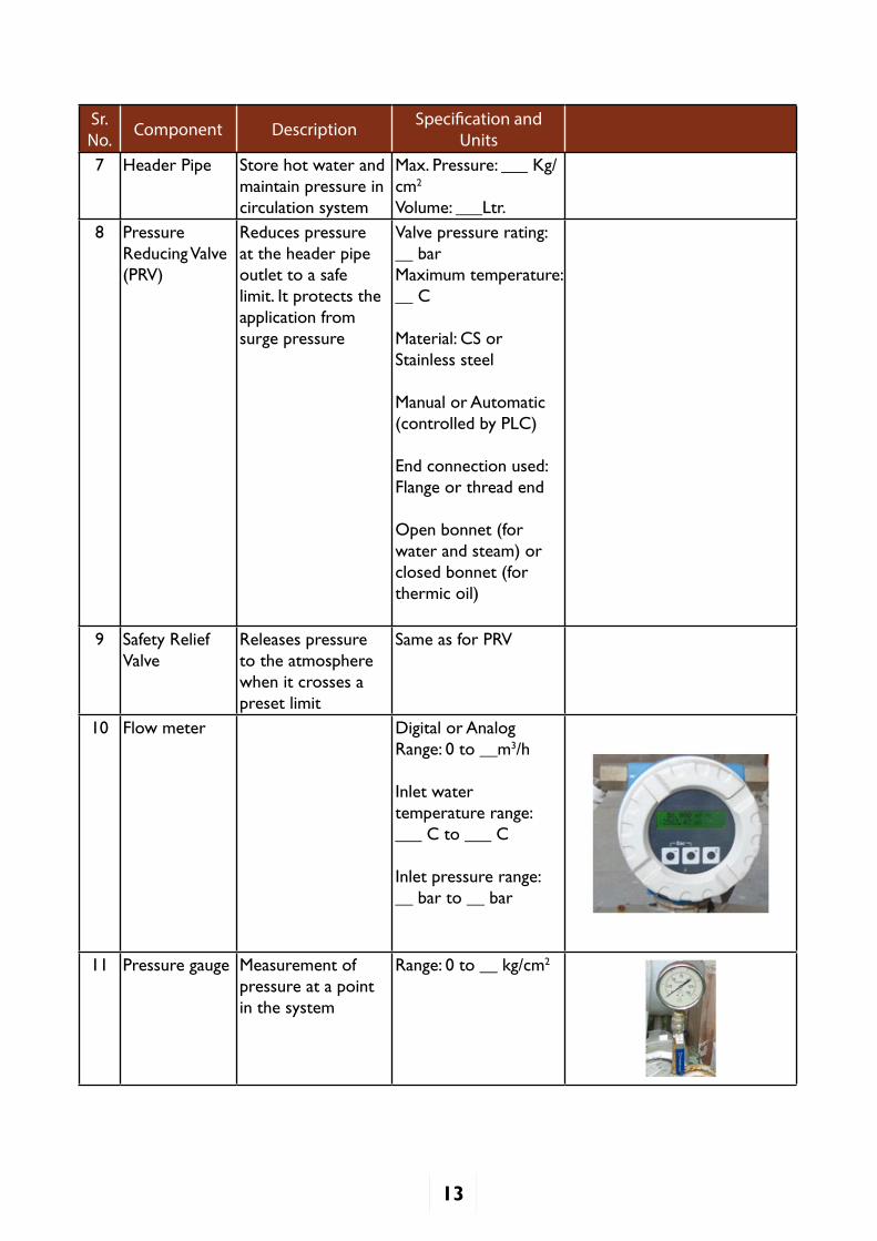
Sr. No. Component Description Specification and
Units7 Header Pipe Store hot water and
maintain pressure in circulation system
Max. Pressure: ___ Kg/cm2
Volume: ___Ltr.8 Pressure
Reducing Valve (PRV)
Reduces pressure at the header pipe outlet to a safe limit. It protects the application from surge pressure
Valve pressure rating: __ barMaximum temperature: __ C
Material: CS or Stainless steel
Manual or Automatic (controlled by PLC)
End connection used:Flange or thread end
Open bonnet (for water and steam) or closed bonnet (for thermic oil)
9 Safety Relief Valve
Releases pressure to the atmosphere when it crosses a preset limit
Same as for PRV
10 Flow meter Digital or AnalogRange: 0 to __m3/h
Inlet water temperature range:___°C to ___°C
Inlet pressure range:__ bar to __ bar
11 Pressure gauge Measurement of pressure at a point in the system
Range: 0 to __ kg/cm2

14
Sr. No. Component Description Specification and
Units12 Temperature
gaugeMeasurement of temperature at a point in the system
Range: 0 to ___°C
13 Direct Cooking Vessel
Has perforated base which is used for cooking rice, boiling potatoes with steam
Capacity in Litres
14 Jacketed Cooking Vessel
For cooking dal, sambhar, soup, etc. with steam/hot oil
Capacity in Litres
15 Steam Trap To remove condensate from steam distribution line, while trapping the steam and not letting it escape
--
In Scheffler steam cooking system, the water softener system softens fresh inlet water by removing dissolved minerals such as calcium and magnesium to prevent scaling. This soft water is then stored in the feed water tank, from where it is pumped to the header pipe, whenever level in it goes below its minimum Water Level (as specified by manufacturer). The Scheffler dish heats up the water to form steam, which gets collected in its upper portion. This steam passes through insulated steam line to process heat application, like for indoor cooking. Here we have two types of vessels- direct cooking vessels and jacketed cooking vessels.
Steam Trap at the bottom of a jacketed cooking vessel collects condensed steam (water) and moves it out of the vessels while trapping the steam inside the vessel. Condensed Steam is collected in condensate recovery tank, from where it is pumped back to header pipe. If at any stage steam pressure in vessel exceeds its designed pressure due to some failure, or due to a hammering effect, safety relief valves opens-up to protect vessels from excess pressure.
3.4 P&I DiagramA P&I (Piping and Instrumentation) diagram shown below in Figure 5 is used by engineers to represent a full system view of the components in a typical system and the flow of fluid through the system. Interpretation of this diagram is useful to diagnose and rectify problems.

15
Figu
re 5
: P&
I Dia
gram
of S
chef
fler
Dis
h ge
nera
ting
Stea
m fo
r C
ooki
ng P
urpo
se
16
4.0 Description of Reflecting, Receiving and Tracking Mechanisms
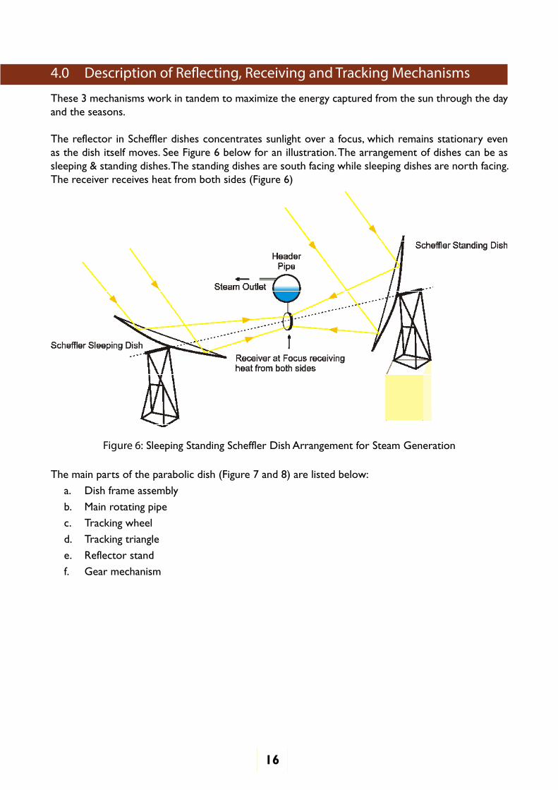
These 3 mechanisms work in tandem to maximize the energy captured from the sun through the day and the seasons.
The reflector in Scheffler dishes concentrates sunlight over a focus, which remains stationary even as the dish itself moves. See Figure 6 below for an illustration. The arrangement of dishes can be as sleeping & standing dishes. The standing dishes are south facing while sleeping dishes are north facing. The receiver receives heat from both sides (Figure 6)
Figure 6: Sleeping Standing Scheffler Dish Arrangement for Steam Generation
The main parts of the parabolic dish (Figure 7 and 8) are listed below:
a. Dish frame assembly
b. Main rotating pipe
c. Tracking wheel
d. Tracking triangle
e. Reflector stand
f. Gear mechanism

17
Figure 7: Daily Tracking Mechanism in Scheffler Dish
Figure 8: Daily Tracking System for Scheffler Dish
Scheffler Dish tracking can generally be of two types:
1. Single Axis Tracking- Automatic daily tracking but manual seasonal tracking
2. Dual Axis Tracking- Automatic daily tracking and automatic seasonal tracking

18
Tracking of Reflector in Scheffler Dish:
1. Daily Tracking (East to West):
In order to compensate for west-east rotation of the earth Scheffler Dish moves from east to west. As shown in Figure 9 Dish moves by 1° every 4 minutes about rotating pipe.
Electronic Timer is driving 12 Volt Wiper Motor, which accurately controls rotation of Schef-fler Dish, by Pulse Width Modulation Technique at fixed Duty Cycle. Speed of Wiper Motor is controlled by changing Duty Cycle of output power as,
Speed of Wiper Motor ∝Duty Cycle
Where, Duty Cycle (D) = Ton T
Wiper Motor thereafter rotates Gearbox (min. Gear Ratio 1: 60), which transmits power to GI wire rope, connected through Wire Rope Drum. This GI wire rope connects Scheffler Dishes in a row to a common Tracking Wiper Motor.
In Scheffler Dish, with sun’s movement from east to west, the dish continuously turns about an axis, tracking sun’s radiation and maintaining the focus of collector on the receiver tube. The axis of daily rotation is located exactly in north-south-direction, parallel to earth axis and runs through the center of gravity of the reflector. The GI wire passes on C-Channel of rotating support of Scheffler through bicycle hub support as shown in Figure 8.
GI Wire pulls the Reflectors in clockwise direction during tracking period. To counter force from GI wire a dead weight (counter weight) is hung to rotary support on counter weight circle.
1) Seasonal Tracking (North – South)
Seasonal tracking is done to change position of Reflec-tor in N-S direction depending on position of the sun. Mechanism providing lever and screws are mostly used, however new system incorporate linear actuators.
• Very slow Seasonal Movement, i.e. 23.5° in three months
• Needs adjustment in 3-4 days
• In India, dishes are more vertical relative to ground during winters and flat in summers
Figure 9

19
Figure 10: Correct position of focus falling on the receiver(Concentrated and at the center of receiver)
Seasonal Adjustment is done by a telescopic bar at each end of the reflector. There are two ways of doing Seasonal Adjustment:
1) Manual Adjustment (as explained in STP 03)
2) Automatic Seasonal Tracking with linear actuators to move dish up or down
5.0 Circulation System - Steam vs Thermic Fluid
Sr. No. Steam Systems Thermic Fluid Systems
1 System Pressure Steam based systems are high pressure fired systems, hence require engineer’s supervision
Most thermic fluid systems operate at relatively low pressure, hence don’t require constant engineer’s supervision
2 Corrosion Air in combination with hot water and salts can cause corrosion / Nitrogen gas used with expansion tank to maintain pressure and supress effect of corrosion
Non corrosive fluids, providing high degree of metal finish protection as provided by lubricating oils
3 Maintenance Require frequent maintenance, but easier to maintain
Require minimal maintenance
4 Environmental Safety
Water is relatively safer, and is widely used in domestic Kitchen Application
Cannot be directly discharged into sewers, but can be processed and recycled to reuse Inorganic thermic fluids may have toxic property*

20
6.0 Safety Information
An understanding of safety involves three aspects:
• A general awareness of safety risks on the site
• Knowledge of protective equipment that should be available on-site and the specific scenarios when they should be used
• Safety precautions that should be followed for every activity that is undertaken on-site
This section provides general coverage of all of the above aspects. In addition, the safety risks and precautions related to every task can be found in the Standard Task Procedures in the annexure.
NOTE: This is a generalized discussion of safety aspects on CST systems. By no means is thisa comprehensive treatment of all safety risks and precautions. For a more complete understanding of safety, please refer to the manufacturer manual or OSHA guidelines.
6.1 General Safety Risks and Precautions
Human SafetyRisks from High Temperature
• The fluid is at a temperature above 110°C, which is scalding temperature. So any contact with fluid should be avoided
• Pipes and other metal parts carrying fluid are at same temperature and are mostly insulated. However, at any exposed area near insulated hose pipes, the tempera-ture can be high enough to cause skin burns
• The area between the reflector and receiver can be extremely hot
Risks from High Pressure
• The system is pressurized, with fluid/steam at a pressure much higher than atmos-pheric pressure. Thus, on any opening/breakage/crack the fluid/steam can come out as a jet and may come in contact with and injure the human body
• Regularly monitor pressure at header pipe. It should be under safe operating limit (Normal Limit: 10-11 Kg/cm2). If pressure in header pipe exceeds this limit call sys-tem maintenance
• The pressure and safety relief valves should be set and tuned only by a trained person. Follow STP 04 to adjust the safety relief valve
Risks from Concentrated Sunlight
• Concentrated sunlight seen at the reflector or receiver can severely damage the human eye
• Make sure that focus cannot accidently fall on any ignitable material
• Never move or stand between the dish and the receiver, and if at all you are moving in this region keep closer to dish and away from receiver
Risks from Heights
• Catwalk, railings, ladders provided should all be in place and inspected periodically
21
Equipment SafetyRisks to the equipment can occur from the following factors.
• Use of excessive force while handling levers or tightening• Placement of sensitive equipment such as temperature and pressure gauges near sources of
heat. For example: o Temperature and pressure gauges placed close to the receiver and not insulatedo PVC conduit piping or any other non-metallic equipment placed behind the receiver
• Control panel, water pump motor, any other electrical equipment in the field should be prop-erly grounded
• For all rotating equipment, safety guard and protective mesh are to be installed and well maintained• Control panel is to be installed at a suitable place to prevent direct exposure from rain / dust /
sun light /heat
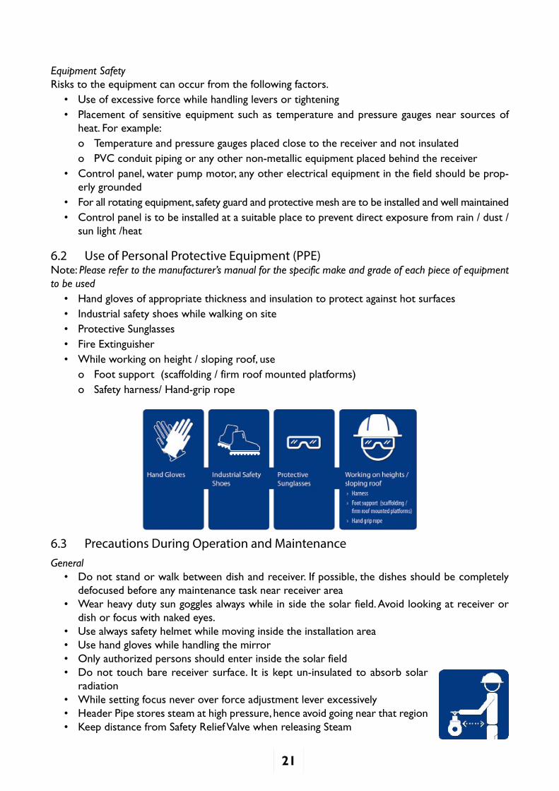
6.2 Use of Personal Protective Equipment (PPE)Note: Please refer to the manufacturer’s manual for the specific make and grade of each piece of equipment to be used
• Hand gloves of appropriate thickness and insulation to protect against hot surfaces• Industrial safety shoes while walking on site • Protective Sunglasses• Fire Extinguisher• While working on height / sloping roof, use
o Foot support (scaffolding / firm roof mounted platforms)o Safety harness/ Hand-grip rope
6.3 Precautions During Operation and MaintenanceGeneral
• Do not stand or walk between dish and receiver. If possible, the dishes should be completely defocused before any maintenance task near receiver area
• Wear heavy duty sun goggles always while in side the solar field. Avoid looking at receiver or dish or focus with naked eyes.
• Use always safety helmet while moving inside the installation area• Use hand gloves while handling the mirror• Only authorized persons should enter inside the solar field• Do not touch bare receiver surface. It is kept un-insulated to absorb solar
radiation• While setting focus never over force adjustment lever excessively• Header Pipe stores steam at high pressure, hence avoid going near that region• Keep distance from Safety Relief Valve when releasing Steam

22
• Do not disturb tracking lever intentionally and once system is set do not disturb any settings at tracking mechanism, seasonal adjustment, gearbox, etc.
While Handling Pipeline and Equipment
• Flexible hose pipes are generally susceptible to leakages due to high pressure in the system, hence maintain safe distance
• Ensure isolating valves are closed to stop the flow of fluid before attending to a module or component
• Drain hot fluid first through vents before opening any equipment to avoid any chance of contact
• Loosen screws and connections only when the system is not under pressure
• Wear gloves while removing insulation to avoid skin contact with hot surfaces
• If fluid is to be drained by opening the pipe flanges or coupling, ensure:
o Most of body part is above the pipeline
o Stand away from pipe-line while opening drainage valves to avoid fluid spill over the body
While Handling Receiver & Header Pipe
• Release steam completely by pressing handle on safety relief valve before opening any equip-ment, to reduce pressure in Header Pipe to atmospheric pressure
While Working on the Scheffler Dish
• When working on the dish at a height, ensure that grip for hands and support for feet is available to avoid from falling
• Dish is made up of glass and is not strong enough to support any load on its surface– ensure that other supports are available before undertaking any work with the dish
• Close top/bottom needle valves of water level gauge before removing glass tube to clean it from the inside
6.4 Chemicals used and health related precautions
Use Soft Water
• It is safe for use and has no health related issues
• Soft water can be safely released to atmosphere to control pressure in the system as water/steam has no toxic effect on environment
Thermic Fluid Precautions
• Maintain good ventilation around equipment area to provide quick cooling of any leaks. This will also disperse any unreacted vapors
• Safety relief valve should be connected to a vessel to discharge thermic fluid safely, as fluid may be toxic and unsafe for release to environment
6.5 IBR (Indian Boiler Regulations) Safety RegulationsSteam Boilers exceeding 22.75 Liters capacity, Steam Pipelines where steam pressure exceeds 3.5 Kg/cm2 come under the scanner of IBR regulations.
All valves & fittings should be as per IBR specifications with test certification for each valve. During repair work technician should follow IBR Regulations & specifications for tasks such as procuring material, welding & plumbing works near Steam Boilers & Steam Pipelines. Operator should refer to manufacturer’s specifications for valve/fitting to be replaced.
23
7.0 System Operation
7.1 Startup Sequence
Step Description
1 • Ensure compliance to all safety factors as mentioned in the chapter of Safety
2 • Turn on all MCBs in Solar Tracking Control Panel
3 Ensure Sufficient Water Supply• Check soft water level in the feed water tank and / or in the steam drum. Level has to be
maintained minimum 50 % of level gauge on steam drum. (Refer to manufacturer manual for exact limits).
• If water level is lower than 50% then:n If there is enough water in Condensate Recovery Tank then start water Pump WP2 to
fill Header Pipes. If not,start Water Pump WP1 to fill Header Pipe from Feed Water Tank.
n Then, open Valve (V1) to fill Header Pipe to the 50% water level mark, and then close it back
4 Start Reflector Dish Tracking MechanismElectronic Timer• Bring the dishes to the morning position using the mechanism available on the specific
system• Put all the dishes/rows on auto mode so as to track the sun from east to west direction• Once the timer is set, the focus of the system will be at a single point throughout the day
Electronic Timer with PLC based automated tracking• Completely automated dishes themselves bring the dish to set sun’s rays on Receiver,
and thereafter track focus of the system to a single point throughout the day• Seasonal Adjustment if not automated, should be done in every 2-3 days
For both manual and automated systems, the focus on the receiver may have to be centered so as to gain the maximum energy output from solar:
• Rotate sprocket handle attached with gearbox to manually turn the dish to reflect Sun’s rays onto the receiver. Focus should be at the center of Receiver, otherwise make adjustment (See STP 03), to bring focus to the center of receiver
OR• Use forward or reverse inching buttons provided on the control panel to set the focus
5. Wait for Pressure to Build up• Once the pressure starts rising in the steam drum, open the drum vent valve and ensure
steam is coming out of vent• When drawing steam from header pipe, first drain condensate water in steam line from
any steam vent of the line, till only saturated steam is coming out.• Once the desired (set) pressure is reached at steam drum, drain the stagnant water in
the process pipeline first with the help of valve provided for a minute, and open the process utility valve for the utilization of the steam

24
7.2 Start-up Precautions• Planned routine maintenance should be done before starting up the system in morning as the
system is cooled down at this stage
• Ensure that overload trip lamp is not glowing. If glowing, correct the fault
• If thermic fluid is used in circulation system, it should be initially heated up by 20°C per hour till it reaches 100°C, so that all moisture is removed from the thermic fluid
• Never use hard water to fill the Header Pipe, as it can cause scaling in the system
• Check that counter weights are properly hung through the pulley
• Check for GI wire ropes, to make sure that they are free to move around pulleys
• Electrical wires, rubber pipes should be either hidden, or kept at ground near dish, to protect them from burning due to excessive heat
• Ensure that valves on steam line are closed when not using steam
7.3 OperationSetting of the focus correctly on the receiver may be required at any time during the operation. Refer to STP 03 at the end of this document for more details. For a different version of the same procedure, please also refer to Appendix 3.
Operation for PLC Based Control Panel
1. If by evening or earlier the dishes reach their extreme end, motors move dishes back to homing position automatically by sensing reverse limit switch.
2. Once the dish reaches to home position, it touches to forward limit switch, which automati-cally stops the entire system
3. It is necessarily expected that positions of all dishes are properly and mechanically synchro-nized
Operation for Timer-Based Control Panel ( Non-PLC Based)
1. Operator has to adjust the position of dish so that sun focus is at the center. Forward and reverse inching push buttons to be used to adjust the position as desired. Operator shall never use inching buttons while auto mode is ON.
2. After adjustment of dish positions, again heating switch shall be put ON.
3. Now depending on the timer ON/OFF duration setting, the dish moves in forward direction in steps. 01 sec ON and 18 sec OFF time is set. If required the setting can be changed on the timer.
4. This tracking shall continue for the whole day automatically. (Battery power is used for this purpose. Battery keeps on charging whole day if panel is provided)
5. At the end of the day when dish motor reaches and touches the ‘full forward limit switch’, forward movement of the motor stops. Now the motor draws power from grid and starts reversing automatically. At this moment the operator being evening time shall stop the heat-ing by switching OFF the heating switch. The dishes shall reverse back to original position and touch ‘full reverse limit switch’ and stop.
6. Second day same operation shall be repeated by the operator.
7. It is necessarily expected that positions of all dishes are properly and mechanically synchro-nized.

25
In Manual Mode, the individual motors can be adjusted by using the Push Button on the Push Button Station on the respective dish row
7.4 Monitoring and Control• System parameters should be monitored regularly. An illustrative example of a monitoring table
to be followed is shown below:
System Parameters for Normal Operation (Illustrative Example - Actual Values will vary by Manufacturer)
System Parameter Value
Set maximum pressure in header pipe 10 Kg/cm2
Set minimum pressure at steam line Depends on application
Water level in header pipe * 75 % water level
Dry saturated steam generated for minimum solar radiation 450 W/m2
5 Kg/hour
Set pressure limit at steam line near cooking vessel* 2 Kg/cm2
• Monitor pressure at the point where steam is being utilized. It should be within safe limit of the device which is utilizing that heat. Take readings of the operating parameters in a logbook. Some examples of the logbooks that could be used are shown in Appendix 2
• If dish is moving too fast or too slow and the focus is out of place, follow STP 3, to adjust the timer.
• Monitor pressure in expansion tank. Safety relief valve should always go off to vent out excess steam,
• If the safety relief valve does not open after pressure crosses safe pressure limit shut down the system and call maintenance.
7.5 Exceptions and Backup• Power Failure Power backup is supplied along with system to run electronic timer during power cuts. In case
backup power is also not working, manually defocus dishes to sleep mode so as to protect insulation near receiver from any damage due to concentrated heat.
• Not Using System for Long Time/Rainy Seasono Turn the dish to morning or evening position facing downwards
o Give proper shading, cover items like Timer(daily Tracking Device)/PLC, wiper motor, Valves, Gearbox, Safety Relief Valve, Pressure Reducing Valves, etc.
o Flush out water from the circulation system
o Turn off all MCB’s in Solar Control Panel
7.6 Shutdown Sequence There are different sets of action followed for different type of systems:
1) Electronic Timers Go-to Timer and press shut down button. The dish starts turning in anti-clockwise direction.
When the dish reaches sleep position release shut down button.

26
Some timers have option to automatically bring dishes to morning position at a set time in the afternoon.
2) Electronic Timers with automated Tracking/PLC’s Electronic timers with pre-set time after which it automatically brings back dish to morning
position
3) Manually Dish can also be brought manually to sleep position by rotating Sprocket Handle.
7.7 Shutdown Precautions• Don’t touch receiver and header pipes as the system is hot
• Valves connected with header pipe don’t require to be operated during day to day operation except for steam globe valve on Steam Line outlet from Header Pipe.
• Dish should be defocused to morning position, otherwise it may fall on any nearby object and this concentrated heat can damage it
• Reflected sunlight from the dish should not fall on windows of nearby homes
8.0 Maintenance
An exhaustive list of maintenance items is provided below. A sample maintenance chart to be used on site is provided in Appendix 4.
8.1 Predictive and Preventive MaintenanceTo isolate any module, close down respective gate valves for it before doing the maintenance.
Reflectors and Receivers
• Clean reflector dishes or whenever the mirrors are dusty and reflectivity is reduced
• Twice a year, check for broken mirrors
o Schedule to replace them soon if there are five or less broken mirrors in a dish
o Schedule immediate replacement (recommended) if there are five or more broken mirrors in a row
• Every five years or whenever necessary check for mirror degradation as shown in Figure 11 below. Check
o Reflectivity of the mirrors should be more than 90%
o Deterioration of mirrors affects the performance of the system
o Replace blind mirrors (with reflectivity less than 80%)
Mirror with poor reflectivity
Mirror with poor reflectivity
Good Mirror with reflectivity more than 90%
Figure 11: Mirror Condition

27
• Annually, undertake structural painting and repair of the system to improve its life span
• Twice a year, apply black coating on receiver with paint as per manufacturer’s specification to improve system’s performance
Circulation System
• Annually, check for scaling at inner linings of Receiver and Header Pipe as shown in Figure 12.
o Scaling & its effect on system’s performance has to be visually determined.
o This maintenance task is generally outsourced because it is rarely performed and requires descaling systems & industrial grade descaling chemicals
• Weekly, check for leakages in the system. Due to high pressure in the systems, system is susceptible to leakages especially at points like the Rubber Washer in the Water Level Indicator, flexible hose pipe. Perform this operation when you spot leakages in circulation pipe
o Identify the point of leakage and remove insulation for that component
o Repair/Replace component with leakage
o Leave insulation material (mineral wool) open to dry off, and then put it back
• On the onset of monsoon remove all the water from the header pipes. Open Blind Plugs con-nected at the bottom of steam pipelines. This will flush out rust & impurities from pipelines along with water from header pipe
• After the monsoon, add fresh RO/DM water in circulation system & then start the system
• Annually, calibrate Temperature Transmitter, Pressure Transmitter, Flow meter and other gauges
• Annually, replace soft water resin (if applicable)in RO water purifier
• Quarterly, clean Screen in Y-Strainers with brush or by soaking it in a clean solution
• Twice a year, clean RO system Cartridge Filler
Tracking System
• Quarterly check that GI wire rope is tightly hung at end points in the tracking system. GI rope can be tightened by U-clamps
• GI Wire should be able to move freely about cycle hubs
• Quarterly check for the movement of cycle hubs
• Replace hubs which are deformed due to excessive weight
• Quarterly, grease & lubricate moving parts in the system as shown in Figure 13. Lubrication should be done specially after rainy season
o Lubricate brackets and screw of rotating pipe
o Screws & Levers in seasonal adjustment rods
o Cycle Chain on GearboxFigure 13: Greasing of moving parts
Figure 12: Scaling of Inner Lining of Pipe

28
8.2 Consumable ReplacementFollowing are the consumable parts in Scheffler System, and hence need standby stock:
1. Coating for receiver as per manufacturer’s specifications
2. Resin for RO water purifier
3. Feed water if there is no water source near Scheffler Solar System
4. Oil & Grease
5. Mirrors (Though not consumable, but some spare mirrors (around 25 mirrors per dish) should be stocked as replacement for broken mirrors)
8.3 Maintenance Do’s and Don’tsDo’s
• Carry out maintenance as per the drawn maintenance schedule
• Maintain the operation and maintenance log book every time as defined in the log format
• For any maintenance work, ensure that power supply to control panel is switched off and dishes are defocused from the receiver
• Follow all the requirements about safety as specified in the Chapter on Safety
• Ensure all the settings(temp and pressure) are as per the design criteria
Don’ts
• Do not clean the mirrors with dry cloth or with paper
• Do not clean mirror after 8.00 am & before 5.00 pm
• Do not modify the system without written approval from the manufacturer
• Do not touch the Receiver when focus is on the receiver
• Do not walk in between receiver and dish during operation
• Do not stop water circulation till temperature drops to 60ºC
• Do not use hard water for mirror cleaning as it may form scaling on mirrors and thus reducing performance

29
9.0 Troubleshooting
Symptom Problem reasons(WHY-1)
Problem reasons(WHY-2)
Problem reasons(WHY-3)
Problem reasons(WHY-4)
Corrective action
1 System not starting in the morning
1.Control Panel not switched on
Control Panel physically not Started
Main switch to be switched ON and ensure indicating lamps glows
Problem in main distribution panel
Main distribution panel to be checked and correct the fault
2.Problem in incoming power for control Panel
Physical damage to the incoming cable
Incoming cable not routed properly
Check/correct incoming supply to control panel and / or replace the cable if required
Short circuit at main distribution line
Cable damage Check/correct/replace the main distribution
3.Main MCCB not working in Control Panel
MCCB Tripped Due to overload Check and replace MCCBShort circuit in control panel
Check/correct the fault
Malfunctioning of MCCB
Repair/replace the MCCB
Short circuit in any of the motors or circuit
Check and correct the fault
2 Scattered focus
1.Improperly fixed mirrors
Fixing arrangement not tightened properly
Check/adjusted alignment of mirrors.
2.Mirrors not cleaned
No manpower available Identify manpower from client end for dish Procedure not followed Follow process as per the O & M ManualSoft water not available Mirror to be cleaned only with soft water Proper tools not available
Hose pipe with nozzle, mopping brush and wiper to be arranged for cleaning mirrors.
3.Low radiation No option4.Fine tuning not done
Nut jam for fine adjustment
Make the adjustment nut free and fine tune the connection
5.Mirrors tainted Bad quality of Replace mirrors with Thermax supplied solar grade mirrorsprotective coating
Domestic mirrors used Corrosive weather/Coastal Area
3 Auto forward not happening
1.Problem in the contactor for forward motion
Carbon deposited on internal contacts
Loose contact Check/clean/correct/replace contactor with same specs and tighten the electrical terminations
2.Problem with the PLC
Program not functioning properly
Improper earthing to PLC panels
Check/correct in coordination with PLC engineers and provide separate instrument earthings for PLC panels
3.Problem in one the limit switches
Limit switch damaged Limit switch stuck up Check/replace/repair Limit switch
4.Problem in gear motor
Winding burnt Due to overload on motor
Check/replace/repair Gear motor
5.Problem in gear box
Gear box jam No Lubricant for Gear Box
Check/repair Gear box
4 Water Pump not operating
1.Problem in signals from Mobrey
Magnetic switch not functioning properly
Repair/replace magnetic switch
Float stuck up inside Clear FloatProblem in electrical connection inside Mobrey
Check and correct the electric connections
2.Problem in contactor for water pump
Carbon deposit on internal contact
Loose contact Check/replace/correct/clean contactor the same
3.Problem in rotary switch for water pump
Internal contact burnt Loose contact Check/replace rotary switchWiring not proper Correct the wiring as per wiring diagram
4.Problem in V-belt for pulleys
V belt worn out Check tension/replace V - Belt
Slippage of V belt on Pulley
Check tension/replace V - Belt
Courtesy: Thermax Ltd.

30
5 Focus not exactly at center of receiver
1.Dish/Dishes not tracking properly
No supply to AC motor from Panel
Problem in wiring Check proper supply to panel and motor and / or rectify
Problem in contactor for AC motor
Check contacts and replace if required
Improper alignment of tracking wheel wrt gear box
Distortion in tracking wheel
Check and correct for any distortion in tracking
Wire rope locking arrangement loose
Check and tight the locking arrangement
Distortion in aluminum rectangular tube linkage
Overload on the linkage mechanism
Centre to center distance in holes of aluminum rectangle is not as per the requirement
Check and correct if required the distance as per drawings
Back bearing nut of rotating pipe is over tight
Loose the back bearing nut and ensure
Top bearing part over tight and thus restricting the dish movement
Loose the top part cover and ensure free movement of dish
Improper alignment of dishes
Check and correct the alignment as per the procedure given in installation manual
Improper jointing of aluminum tubes
Correct the joint and tight the nut and bolts for proper load distribution
Overload on the linkage mechanism due to high speed of wind
Do not operate the system during high wind condition and tie dishes with reflector stand properly with ropes so as to avoid damages
Inadequate distance between dishes
Improper installation Take prior approval from Engineering for any correction to be made
Inadequate layout size
Take prior approval from Engineering for any correction to be made
Inadequate distance between dish & receivers
Improper installation Take prior approval from Engineering for any correction to be made
Improper Layout size Take prior approval from Engineering for any correction to be made
Receiver inclination angle not as per requirement
Inclinometer not available during installation
Angle to be checked with inclinometer
Negligence during installation
Make alignment report and get it approved
2. Dish movement is jammed
Under sizing of hole at channel
Back bearing nut of rotating pipe is overtight
Check hole of back bearing channel and correct as per requirement
Oversizing of bolt at rotating pipe
Top bearing part overtight and thus restricting the dish movement
Check and loosen the top part
Improper lubrication at top part assembly
Ensure proper lubrication and free movement of bolt
3.improper dish balancing
Balancing weight not installed
Check and correct balancing
4.Improper seasonal adjustment
Side rope not properly tight
Approach ladder not available
Check/adjust upper and lower seasonal ladder
Locking of adjustment levers not tight
Locking arrangement to be tightened properly
Fine adjustment not done
Nut jam for fine adjustment
Make the adjustment nut free and fine tune the connection

31
6 Water pump not developing pressure
1.Problem in NRV Dead weight inside stuck up and not operating
Check/rectify/replace NRV
Direction of NRV not Proper
Correct the direction as per requirement
2.Suction strainer choked
Excessive dust in water from piping
Water tank not cleaned
Clean the water tank and flush the piping till
Wire mesh of strainer clogged with permanent scale
Hard water getting used for operation
Use only soft water to clean the strainer Replace the water treatment equipment, if required
3.Problem with the valve seat assembly
Wear and tear of valve seat assembly
Hard water getting used for operation
Softener not available
Check/replace valve seat assembly
Spring tension not proper
In operation since long time
No breaks for regular maintenance
Adjust/replace the spring tension
Foreign particles inside the valve seat assembly
Strainer not cleaned Maintenance not done properly
Clean the valve seat assembly properly during preventive maintenance
4.Problem in gland washer
Wear and tear of Gland washer
Wear and tear of pump shaft
Check shaft for smoothness, Replace gland washer
Gland washer rubber hardened
High temperature of inlet water
Maintain inlet temp of the water within 70 degree C Replace gland washer
Water leakage form Gland washer assembly
Foreign particles between shaft and Gland rubber
Strainer not cleaned
Clean the gland water and strainer
5.Faulty pressure gauge
Isolation valve closed Negligence Open the isolation valveSpring tension lost Over Pressure Repair/replace the pressure gauge
6.No Water in feed water tank
Softener is not working Resin property lost Replace Resin Replace softener
7 Pressure not developing in stream drum
1.Low radiation Cloudy weather, Fogging
Wait for clear atmosphere
2.Focus not on receiver center
As per above point no 2
As per above point no 2
As per above point no 2
As per above point no 2
3.No water steam drum
Pump not working Level controller not functioning
Check level controller and make the water pump operational. Repair if required
Level gauge functioning Gauge glass valve choked
Clean the gauge glass valve and ensure the tube shows water level
Operator Negligence At the start it should be a standard practice for steam drum filling
4.Scatterd focus As per above point no 3
As per above point no 3
As per above point no 3
As per above point no 3
5. Less focus intensity
Mirror tainting Replace tainted mirrorLow radiation Wait for clear atmosphere
6.Faulty pressure gauge
Isolation valve closed Negligence Open the isolation valve
Spring tension lost overpressure Repair/replace the pressure gauge

32
8 Steam continuously blowing from drum safety valve
1.Problem in safety valve
Valve seat wear and tear
Check/replace the seat of safety valve
Scale formation on valve seat
Hard water being used for operation
Softener not functioning properly
Recharge softener, clean the valve seat.
Spring tension lost Overnighting of the spring
Replace the safety valve spring
2. Restriction to steam flow
Main steam stop valve or isolation valve at Application point closed
No utilization of generated quantity of steam at process
Open the valves and utilize the solar stream to the maximum possible extent
Problem in NRV In outlet line
NRV direction not as per requirement
Negligence during installation
Check/replace/rectify NRV
Flap / Dead weight inside got stuck up
Scale formed dust inside the NRV casing
Check and ensure free movement of flap / dead weight steam flow
Choked steam piping Hard water being used for operation
Softener is not functioning properly due to operational negligence
Remove chockingReplace choked portion of piping
Thicker welding penetration inside the welding joint causing very small diameter
Improper welding or poor workmanship
Check/replace the choked portionWelding to be done by skilled, experienced welder
9 Drum pressure rising continuously
1.Faulty pressure Gauge
Spring tension lost Over-pressurizing of steam
Replace pressure gauge
2.Main steam stop valve closed
Negligence during operation
Open the valve and start utilizing the steam from solar
No utilization of steam at the application point
Open the valve and start utilizing the steam from solar
3.Problem in outlet the NRV
NRV direction not as per requirement
Negligence during installation
Check/rectify/replace NRV
Flap / Dead weight inside got stuck up
Scale formed dust inside the NRV casing
Check and ensure free movement of flap /dead weight for smooth steam flow
4.Underutilization of generated quantity of steam process
System is producing more steam then requirement
Solar steam shall be used to maximum possible extent
5.Choked steam piping
Hard water being used to operation
Softener not functioning properly due to operational negligence
Remove choking/replace choked portion piping
Thicker welding penetration inside welding joints causing very small diameter to pass the steam
Improper welding and poor workmanship
Check and replace the choked and welding to be done by skilled, experienced welder

33
10 Auto reverse not happening
1.Problem in PLC Program not functioning properly
Improper earthings to PLC panel
Check/correct in coordination with PLC engineer and provide separate instrument earthings for PLC Panel
2.Problem in contactor for reverse motion
Carbon deposited on internal contacts
Loose contact Check/correct/clean/replace contactor with same specs and tighten the electrical termination
3.Problem to limit switch for reverse
Limit switch damaged Limit switch stuck up Check/repair/replace Limit Switch
4.Problem in gear motor
Winding burnt Due to overload on motor
Dish movement jam
Check/replace/repair Gear motor
5.Problem in Gear Box
Gear box jam No Lubricantion for Gear Box
Check/repair Gear box
Sprocket wheel teeth broken
Due to improper alignment
Make proper alignment
Bearing Jam Non lubrication ,rusting
Clean the bearing part, make proper lubrication, and ensure smooth
Gear box shaft bend Due to overload
Proper alignment to be done avoid the overload on shaft, replace the shaft if required
Additional Troubleshooting NotesSymptom Probable Cause Action
Noise in circulation pump Alignment of pump motor disturbed
Refer to Pump/ motor manual to realign the pump/motor
Pressure of suction pump lower or equal to saturation pressure of water at that temperature
Check pressure of compressed air in expansion tank; It must be above 3 Kg/cm2. Rectify as required
Pressure at Pump fluctuating
Air entrapment in the water system
Open and close vent valves in the water piping, one at a time to remove trapped air
Y-strainer is choked Clean the filter (refer to STP 1)
The pump is cavitating due to hot water under pressure
Check pressure of compressed air in expansion tank; It must be above 3 Kg/cm2. Rectify as required
Receiver is deforming from its Shape
Very less/ no water in in header pipe
Defocus the dish immediately
Fill water in header pipe
Set the focus of the dish back on receiver
Timer which tracks the dish not working properly
Refer to STP 3 to adjust /set focus of the dish on the center of the receiver
Power supply problem for the timer
Electric backup battery in the Timer needs to be replaced
System not generating proper steam at expected rate
Refer to Annexure 3 Refer to Annexure 3

34
Appendix 1: Sample Bill of Materials
• Size of the concentrators : 16 mtr2
• Reflective material : 2 mm thick mirror• Reflectivity of the mirror : more than 90%
1) Central Tracking system Automatic type, drive- dc motor 12 volt Reduction gear box, Gear Ratio 1:60 DC Motor tracking by electronic timer.
2) Steam Header.• Material used for steam header : High grade mild steel (Sh 40)• Design pressure : 15 kg/cm2
• Insulation material used : 100 kg/mq. lrb 50 mm thick with aluminium Cladding
3) Receiver• Type : tank type circular• Material : high grade mild steel• Design pressure : 15 kg/cm2
• Working pressure : 10 kg/cm2
• Insulation material : 100kg/mq. lrb with 100mm insulation & Aluminium cladding
4) System steam and feed water piping• Steam header pipe : 10” diameter (IBR Sh 40)• Common header pipe : 10” diameter (IBR Sh 40)• Steam out let line from header pipe
to common Steam collecting line : 1” diameter (IBR Sh 40)• Common steam collecting line from
header pipe : 2” diameter (IBR Sh 40)• Steam out let line from common
header to Kitchen header : 2” diameter (IBR Sh 40)• Common feed water line : 2” diameter (G.I. “C” Class)• Insulation material : 100kg/mq. lrb with 50 mm insulation• Feed water line from common line
to header pipe : 1” diameter (G.I. “C” Class)
5) Valves and fittings • Steam globe valve flange end, MOC: Carbon Steel, IBR• Safety valve Gun metal, spring loaded, Spirex• Pressure Gauge (6” dial, Gauge Range: 0 to 20 kg/cm2)• Syphon Tube, MOC: S.S., “Q” & “U” type• Needle valve, MOC: S.S.• Steam strainer, MOC: C.S., flange end.• Non return valve, MOC: S.S., disc type for header pipe• Non return valve, MOC: C.S., flange end for steam line• Non return valve gun metal screwed end for water line• Water meter for feed water line, gun metal screwed end 1’’ diameter• Water level indicator Make: S.S., screwed end ½’’ diameter

35
• Steam separator seamless made from high grade mild steel• Temperature Gauge PT100 with accessories.• Pressure Reducing Valve, MOC: C.S., flange end, IBR
6) Feed water pump Reciprocating Pump for filling header pipes at required capacity and with required pressure
7) S.S. Tank for treated feed water 5000 Litre. Cap Insulated with rock wool/mineral wool with 3” thick with 100 kg/m3 density
8) Water softening plant Capacity: 5000 Litre/day

36
Log Book (Daily Monitoring)Daily Observation Report on Steam Pressure (Kg/cm2) in different Header Pipes in Scheffler Solar Cooking System:
Steam Header
no.
8:00 AM
9:00 AM
10:00 AM
11:00 AM
12 noon
1:00 PM
2:00 PM
3:00 PM
4:00 PM
5:00 PM
1 2 3 4
Log Book (Weekly Monitoring)Morning System Readings:
Sr. No. Date
System Starting
Time
Feed Water Meter
Reading
Steam Meter
Reading
LPG Cylinders
used
Climate(Sunny/Cloudy/ Rainy)
1 2 3 4567
If System used for cooking Generated Steam (Steam Supply to kitchen)
Sr. No. Date
System Stopping
Time
Feed Water Meter
Reading
Steam Meter
Reading
Rice(kg)
Dal(kg)
Others (Specify) Supervisor Remarks
1 2 3 4567
Appendix 2: Operation Logbooks

37
Solar Steam Generation System-Log Sheet Page 1 of 2
Client Site Project Capacity Solar fild: Type of Mirrors
Solar Steam Generation Date Site Engineer Commissing engineer
Location Data
Parameters Time
Unit 8.00 8.30 9.00 10.00 10.30 11.00 11.30 12.00 12.30 1.00 1.30 2.00 2.30 3.00 3.30 4.00 4.30 5.00
Global Radiation Gb
w/m2
Diffuse radiation Gd
w/m3
Ambient temperature
Ta
°C
Wind speed W m/sec
Solar field
Time
Temperature Unit 8.00 8.30 9.00 10.00 10.30 11.00 11.30 12.00 12.30 1.00 1.30 2.00 2.30 3.00 3.30 4.00 4.30 5.00
Feed water tank T1°C
Pressure
Time
Unit 8.00 8.30 9.00 10.00 10.30 11.00 11.30 12.00 12.30 1.00 1.30 2.00 2.30 3.00 3.30 4.00 4.30 5.00
Steam Drum P1kg/cm2 g
Utility 1: P2 kg/cm2 g
Utility 2: P3 kg/cm2 g
Solar Steam Generation System-Log Sheet Page 2 of 2
Client Site Date
Flow Time
Unit 8.00 8.30 9.00 10.00 10.30 11.00 11.30 12.00 12.30 1.00 1.30 2.00 2.30 3.00 3.30 4.00 4.30 5.00
Feed water totalised
Gb
w/hr
Water Level Time
Initial Feed water tank level (mm) L1
Final Feed water tank Level (mm) L2
Water consumption Ltr/Day
Total Steam Generation: Kg/Day
Remarks:
Appendix 2 (Contd.)Courtesy: Thermax Ltd.

38
Appendix 3: Focus Setting
NOTE: This Section Is Coutesy Of Thermax Ltd.Always start the focus setting from the dish on which the gear box mechanism is installed.
Figure 1: Receiver Focus
a) For horizontal movement of the focus:- Horizontal movement of the focus shall be done with the help of local push buttons provided on
the control panel.
Once the timer is set the focus of the system will be at a single point through out the day.
Note - Side ropes of both sides to be equally tightened so as the focus remains on receiver centre. Length may vary of ropes but the tension should be equal.
b) For vertical movement of the focus:- Use Seasonal adjustment setting by the lever provided and geared motor initially.
Refer fig no 2,3 and 4
Seasonal adjustment is essentially required when the focus is vertically up ward or down ward on the respective receiver.
Circle 01 in Fig 1 – Correct Focus (At the “CENTRE” of Receiver)
Circle 02 in Fig 1– Needs Seasonal Adjustment (Focus vertically “UP” of Receiver)
Circle 03 in Fig 1– Needs Seasonal Adjustment (Focus vertically “DOWN” of Receiver)
Frequency: - Once in two days and carry out the adjustment at 10.00 – 12.00 noon.
We need to adjust the Dish so that focus is always at the centre of respective receiver.
There are two levers with locking arrangements which are provided on the structure for seasonal adjustment.
One lever is at the upper and another is at the lower end of dish. Refer Fig for Seasonal adjustment lower side & Seasonal adjustment upper side.

39
Focus vertically “UP WARD”
1. First unlock and loosen the Lower lever.
2. Adjust the focus with the help of Lower lever so that focus is closer to centre of the respective receiver by pushing LC 2 inside LC 1 Refer Fig No. - 4
3. Lock bottom lever K 5 on satisfactory focus adjustment at the centre.
4. Sharpen the focus at the centre of the receiver (Fine adjustment), by upper seasonal adjustment by unlocking K 2 and rotate R 1 clockwise or anti clockwise Refer Fig No. -6
5. Lock top lever K 2 on satisfactory fine circular focus adjustment.
Focus vertically “DOWN WARD”
1. First unlock and loosen the lower lever.
2. Adjust the focus with the help of Lower lever so that focus is closer to centre of the respective receiver by LC 2 pulling outward from LC 1 Refer Fig No. - 4
3. Lock bottom lever K 5 on satisfactory focus adjustment at the centre.
4. Sharpen the focus at the centre of the receiver (Fine adjustment), by upper seasonal adjustment by unlocking K 2 and rotate R 1 clockwise or anti clockwise Refer Fig No. – 6
5. Lock top lever K 2 on satisfactory fine circular focus adjustment.
Refer photos below for details:-
Figure 2: Seasonal Adjustment Lower Side

40
Figure 3: Seasonal Adjustment-Lower Exploded View
Figure 4: Seasonal Adjustment Upper Side

41
Figure 5: Seasonal Adjustment Upper Side Exploded View
Important Note: Do not tighten excessively the locking arrangement to avoid tension.

42
Appendix 4: Maintenance
Courtesy:Thermax Ltd.
Maintenance activity Daily Weekly Monthly Quarterly Half yearly
Yearly
Calibrate all pressure gauges
*
Calibrate temperature indicators & controllers
*
Clean strainers-feed pump suction
*
Check safety valves operation
*
Dust removal from Elect control panel
*
Clean electrical contactor contacts
*
Check connection of level controller
*
Cleaning gauge glass protector & glasses
*
Grease all rotating parts *
Dismantling, cleaning & lapping of all the Valves, NRVs, Safety Valves, blow-down valves
*
Hydraulic test, up to 1.5 times the max. working pressure for 30 minutes (max)
*
Offer the boiler for the hydraulic test to IBR authority
*
Cleaning of feed water tank
*
Tighten all bolts *

43
Standard Task Procedure 01Cleaning of Y-Strainer
Responsible Person: Technician
Effective Date: 2013-09-05 Revision: 001
This Standard Task Procedures is used:
1. As a learning aid 2. To assess competence
3. As a job aid while performing the function 4. To conduct a Planned Task Observation
Preparation / /
Equipment/tools: Spanner, Brush Material: Cloth, Bucket
Safety Equipment: Other prerequisites:
Documentation to be completed Submitted to By when /
a. Maintenance Log sheet Supervisor On Task Completion
Pre-operational checks Criteria /
Check state of systemSuspected choking of Y-Strainer/Insufficient or inconsistent pressure
Step Criteria: Operating/Safety/Quality /
Prepare for Startup1. Close isolating gate valve
Close isolating gate valve connected just before strainer.
2. Opening strainer Remove isolation from the strainer.
Loosen nuts and bolts from cover with a spanner of suitable size.
3. Collecting sludge in a bucket
Place a bucket under strainer to collect oil. Circulating liquid along with dirt will flow down to the bucket. When no more circulating fluid is coming out, remove filter (screen) from inside the strainer.
CAUTION!
Risk for hand! Wear hand gloves. Check that temperature of circulating liquid is safe to handle before touching it.

44
Step Criteria: Operating/Safety/Quality /
Cleaning of FilterWhen no more circulating fluid is coming out, remove filter (Screen) from inside the strainer.
Clean filter with pressurized water and brush.
Take out sludge from inner side of strainer.
Place back filter after cleaning and tightly close cover with bolts. Put back insulation. Open back isolating gate valve. Start the liquid circulation system. Remove air in strainer through air-vent located at a height near outlet of strainer. After air is removed close back air vent.
CAUTION!
Keep your face and body away from circulating fluid
Risk of Body injury
Wear Gloves

45
Standard Task Procedure 02Removing Insulation for Repair
Responsible Person: Technician
Effective Date: 2013-09-05 Revision: 001
This Standard Task Procedures is used:
1. As a learning aid 2. To assess competence
3. As a job aid while performing the function 4. To conduct a Planned Task Observation
Preparation / /
Equipment/tools: Screw Driver, Wire Cutter Material: Cloth
Other prerequisites:
Documentation to be completed Submitted to By when /
a. Maintenance Log sheet Supervisor On Task Completion
Pre-operational checks Criteria /
Check state of system Poor system temperature or pressure output
Step Criteria: Operating/Safety/Quality /
Prepare for Startup
1. Open Aluminum/SS sheet Open screws of the Insulation line to be opened and take out Aluminum/SS sheet.

46
Step Criteria: Operating/Safety/Quality /
2. Remove wire mesh and insulating material
Untie wire mesh to loosen glass wool from the pipe.Use wire cutter to remove wire mesh if required.
Remove insulating material for inspecting pipeline.
3. Maintenance operation on pipeline/equipment
Perform required maintenance operation on the pipe/component (repair/replacement). Use wire cutter to remove wire mesh if required.
4. Close back pipe Insulation After pipe has been satisfactorily repaired, fold wire mesh around the pipe to be insulated, fill back insulation material in wire mesh and twist metallic ends of wire mesh so as to hold insulation material at its position.
If wire mesh is not in condition to be reused, get a new mesh.
Put back Aluminum/ SS sheets and tighten them with screws.
CAUTION!
Risk for hand! Wear hand gloves.

47
Standard Task Procedure 03Daily Adjustment and Seasonal Adjustment of Scheffler Dishes
Responsible Person: Technician
Effective Date: 2013-09-05 Revision: 001
This Standard Task Procedures is used:1. As a learning aid 2. To assess competence
3. As a job aid while performing the function 4. To conduct a Planned Task Observation
Preparation / /Equipment/tools: Spanner, Brush Material: Cloth, Bucket
Safety Equipment: Other prerequisites:
Pre-operational checks Criteria /a. Check state of system When focus is not at the center of receiver
Step Criteria: Operating/Safety/Quality /Daily Adjustment Tuning of PLC/electronic timer for automatic daily tracking of Scheffler Dish
1) When focus of dish on receiver is lagging (left of center)∑ Go to electronic timer, and increase duty cycle in its panel by
a small fraction of units∑ In PLC/Electronic Timer switch Tracking Mode knob to Manual
∑ Adjust focus of dish on the center of the receiver manually with Handle as shown in figure above. Switch back tracking knob in PLC/Electronic Timer to Auto mode
∑ Observe for some time that if focus of the dish is still lagging, keep on repeating above procedure of increasing duty cycle of tracking unit by a fraction

48
2) When focus of dish on receiver is leading (right of center)∑ Follow same procedure as above, you follow when the focus is
lagging, but in this case keep on substantially decreasing duty cycle by a fraction, till Tracking System starts turning dish in sync with the movement of the Sun from East (Morning)to West (Evening)
Seasonal Adjustment of Scheffler DishCarried out once in very two-three days between 10 and 12 noon
To adjust dish in North-South direction (Seasonal Adjustment) push-pull red seasonal supports (red) as shown in figure on right
1) Focus vertically upwards
First unlock and loosen the lower lever (K5)Adjust the focus with the help of lower lever so that focus is
closer to the center of the respective receiver by pushing LC2 inside LC1
Lock the bottom lever K5 on a satisfactory focus adjustment at the center
Sharpen the focus at the center of the receiver (fine adjustment), by the upper seasonal adjustment by unlocking K2 and rotate R1 clockwise or anti-clockwise
Lock top lever K2 on satisfactory fine circular focus adjustment
49
2) Focus vertically downwards∑ First unlock and loosen the lower lever (K5).∑ Adjust the focus with the help of lower lever so that focus is
closer to center of the respective receiver by LC2 pulling outward from LC1.
∑ Lock the bottom lever K5 on satisfactory focus adjustment at the center.
∑ Sharpen the focus at the center of the receiver (fine adjustment), by upper seasonal adjustment by unlocking K2 and rotate R1 clockwise or anticlockwise.
∑ Lock top lever K2 on satisfactory fine circular focus adjustment.
CAUTION!
Wear hand gloves.
Wear Safety Helmet

50
Standard Task Procedure 04Calibration of Pressure Reducing Valve
Responsible Person: Engineer/Technician
Effective Date: 2013-10-05 Revision: 001
This Standard Task Procedures is used:
1. As a learning aid 2. To assess competence
3. As a job aid while performing the function 4. To conduct a Planned Task Observation
Preparation / /
Equipment/tools: Screw Driver Material:Safety Equipment: Other prerequisites:
Documentation to be completed Submitted to By when /
a. Maintenance Log sheet Supervisor On Task Completion
Pre-operational checks Criteria /a. Check state of system Should not be in working condition
Step Criteria: Operating/Safety/Quality /
Preparation for Calibration
1. Close the System (cooking vessels, boilers, etc.). 2. Monitor inlet/outlet pressure at PRV at temperature gauge.3. Open the top cover on the Pressure Reducing Valve (PRV) in clock-
wise direction.4. Now you can see the adjusting Screw.
5. To increase outlet pressure, turn the screw nut clockwise and screw in anti-clockwise direction while monitoring the outlet pressure, till outlet pressure becomes equal to required set pressure.
6. To decrease outlet pressure, turn the screw nut anti-clockwise and screw in clockwise direction while monitoring the outlet pressure, till outlet pressure becomes equal to required set pressure.
7. Close back Top Cover on Adjusting Screw.
CAUTION!
High pressure in steam pipeline can harm application device, or the operator hence operate carefully

51
Standard Task Procedure 05Calibration of Temperature Transmitter
Responsible Person: Technician
Effective Date: 2013-09-05 Revision: 001
This Standard Task Procedures is used:
1. As a learning aid 2. To assess competence
3. As a job aid while performing the function 4. To conduct a Planned Task Observation
Preparation / /
Equipment/tools: Spanner, oil bath, stirrer, thermometer, resistance wires of different values
Material: Silicone Oil
Safety Equipment: Other prerequisites:
Documentation to be completed Submitted to By when /
a. Operations Log sheet Supervisor On Task Completion
Pre-operational checks Criteria /
a. Check state of system Should not be in working condition
Step Criteria: Operating/Safety/Quality /
Preparation for Calibration
1. Take a vessel.2. Put oil, which can sustain temperature of about 300 °C3. Heat the oil using heater.4. Use a calibrated thermometer to observe temperature of Silicon
oil bath (in range 200-230 °C)
Calibrating Temperature Transmitters
52
Step Criteria: Operating/Safety/Quality /
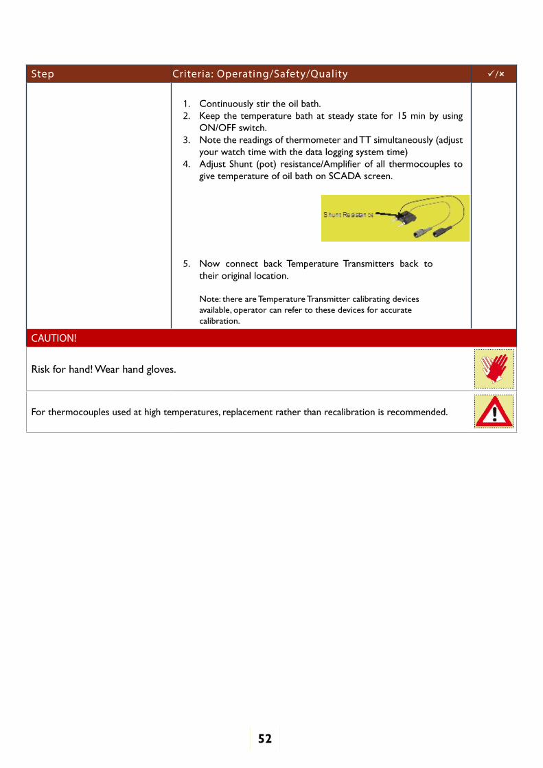
1. Continuously stir the oil bath.2. Keep the temperature bath at steady state for 15 min by using
ON/OFF switch.3. Note the readings of thermometer and TT simultaneously (adjust
your watch time with the data logging system time)4. Adjust Shunt (pot) resistance/Amplifier of all thermocouples to
give temperature of oil bath on SCADA screen.
5. Now connect back Temperature Transmitters back to their original location.
Note: there are Temperature Transmitter calibrating devices available, operator can refer to these devices for accurate calibration.
CAUTION!
Risk for hand! Wear hand gloves.
For thermocouples used at high temperatures, replacement rather than recalibration is recommended.
53
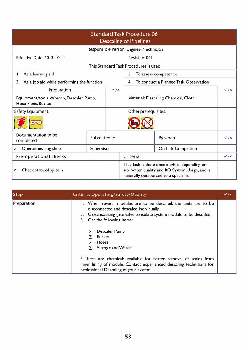
Standard Task Procedure 06Descaling of Pipelines
Responsible Person: Engineer/Technician
Effective Date: 2013-10-14 Revision: 001
This Standard Task Procedures is used:
1. As a learning aid 2. To assess competence
3. As a job aid while performing the function 4. To conduct a Planned Task Observation
Preparation / /
Equipment/tools: Wrench, Descaler Pump, Hose Pipes, Bucket
Material: Descaling Chemical, Cloth
Safety Equipment: Other prerequisites:
Documentation to be completed Submitted to By when /
a. Operations Log sheet Supervisor On Task Completion
Pre-operational checks Criteria /
a. Check state of systemThis Task is done once a while, depending on site water quality, and RO System Usage, and is generally outsourced to a specialist
Step Criteria: Operating/Safety/Quality /
Preparation 1. When several modules are to be descaled, the units are to be disconnected and descaled individually
2. Close isolating gate valve to isolate system module to be descaled.3. Get the following items:
∑ Descaler Pump∑ Bucket∑ Hoses∑ Vinegar and Water*
* There are chemicals available for better removal of scales from inner lining of module. Contact experienced descaling technicians for professional Descaling of your system

54
Setup
Prepare the setup as shown in figure above:1. Place Descaler Pump at the bottom of the bucket.2. Connect Descaler Pump’s outlet to a module (Receiver Tube), with a
hose pipe.3. Fix outlet of another hose pipe in the bucket to collect back
chemical solution from the module
Step Criteria: Operating/Safety/Quality /
Starting Descaling Process
1. Pour Vinegar or Descaling Chemical solution with water in ratio of 1:3 in the bucket
2. Start Descaler Pump3. Alow the solution to circulate for about 1 hour4. Now stop the Pump. Dispense discard descaling chemical in the
bucket into sink
Fresh Water Rinse 1. Fill the bucket with cold water2. Start the Pump to circulate fresh water in the module for about 15
minutes3. You may need to replace fresh water and repeat this procedure of
Rinsing if you notice any residual taste in the module.
You have to individually follow this descaling process for each module.
CAUTION!
Acid Spill, wear Hand Gloves

Prepared by
D-66, 60 Feet Road, First Floor (Above Corporation Bank), Near Chattarpur Temple, New Delhi - 110074 Email: [email protected] Website: www.anthropower.in