schematic design approval request approval level: … tec renewal - final.pdf · project name: uas...
TRANSCRIPT
ldIIJ_S Total Project CostUNIVERSITY OF ALASKASOUTHEAST
Approval Level:SCHEMATIC DESIGN APPROVAL REQUEST
TO: Regent CowellFacilities and Land Management Committee Chair
THROUGH: Kit DukeAVP Facilities and Land Management
THROUGH: Michael CiriInterim Vice ChancelIor
THROUGH: Keith GerkenDirector Facilities Services
FROM: Ke MellProject Manager
DATE: April iS, 2014
SUBJECT: Project Type: R&RProject Name: UAS Technical Education Center Renewal, Phase IProject No.: 2013-02
Cc: John PughRichard Caufield
L $ 1,500,000
FLMC Chair
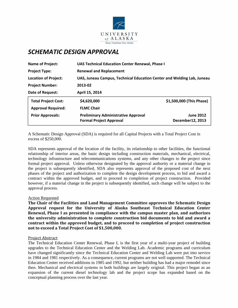
SCHEMATIC DESIGN APPROVAL Name of Project: UAS Technical Education Center Renewal, Phase I
Project Type: Renewal and Replacement
Location of Project: UAS, Juneau Campus, Technical Education Center and Welding Lab, Juneau
Project Number: 2013‐02
Date of Request: April 15, 2014
A Schematic Design Approval (SDA) is required for all Capital Projects with a Total Project Cost in excess of $250,000. SDA represents approval of the location of the facility, its relationship to other facilities, the functional relationship of interior areas, the basic design including construction materials, mechanical, electrical, technology infrastructure and telecommunications systems, and any other changes to the project since formal project approval. Unless otherwise designated by the approval authority or a material change in the project is subsequently identified, SDA also represents approval of the proposed cost of the next phases of the project and authorization to complete the design development process, to bid and award a contract within the approved budget, and to proceed to completion of project construction. Provided however, if a material change in the project is subsequently identified, such change will be subject to the approval process. Action Requested TheChairoftheFacilitiesandLandManagementCommitteeapprovestheSchematicDesignApproval request for the University of Alaska Southeast Technical Education CenterRenewal,PhaseIaspresented incompliancewiththecampusmasterplan,andauthorizestheuniversityadministration tocompleteconstructionbiddocuments tobidandawardacontractwithintheapprovedbudget,andtoproceedtocompletionofprojectconstructionnottoexceedaTotalProjectCostof$1,500,000. ProjectAbstractThe Technical Education Center Renewal, Phase I, is the first year of a multi-year project of building upgrades to the Technical Education Center and the Welding Lab. Academic programs and curriculum have changed significantly since the Technical Education Center and Welding Lab were put into service in 1984 and 1981 respectively. As a consequence, current programs are not well supported. The Technical Education Center received additions in 1985 and 1992, but neither building has had a major remodel since then. Mechanical and electrical systems in both buildings are largely original. This project began as an expansion of the current diesel technology lab and the project scope has expanded based on the conceptual planning process over the last year.
Total Project Cost: $4,620,000 $1,500,000 (This Phase)
Approval Required: FLMC Chair
Prior Approvals: Preliminary Administrative Approval June 2012 Formal Project Approval December12, 2013
SDA UAS Technical Education Center Renewal, Phase I Page 2 of 4
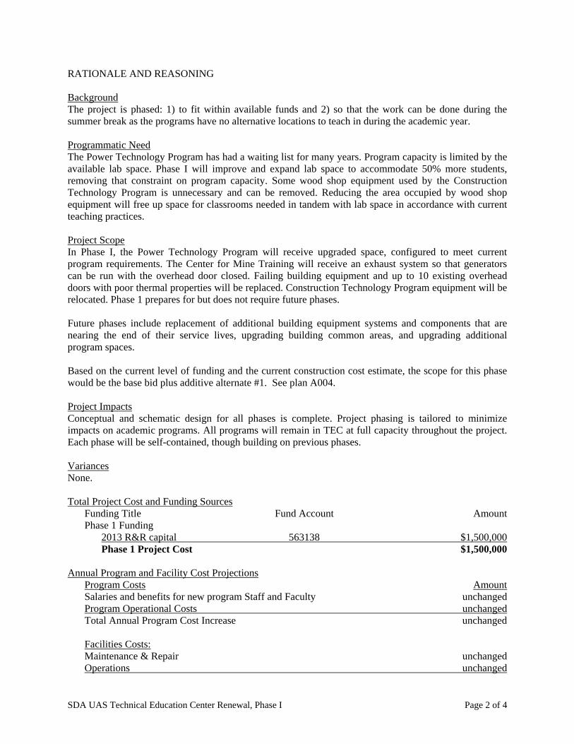
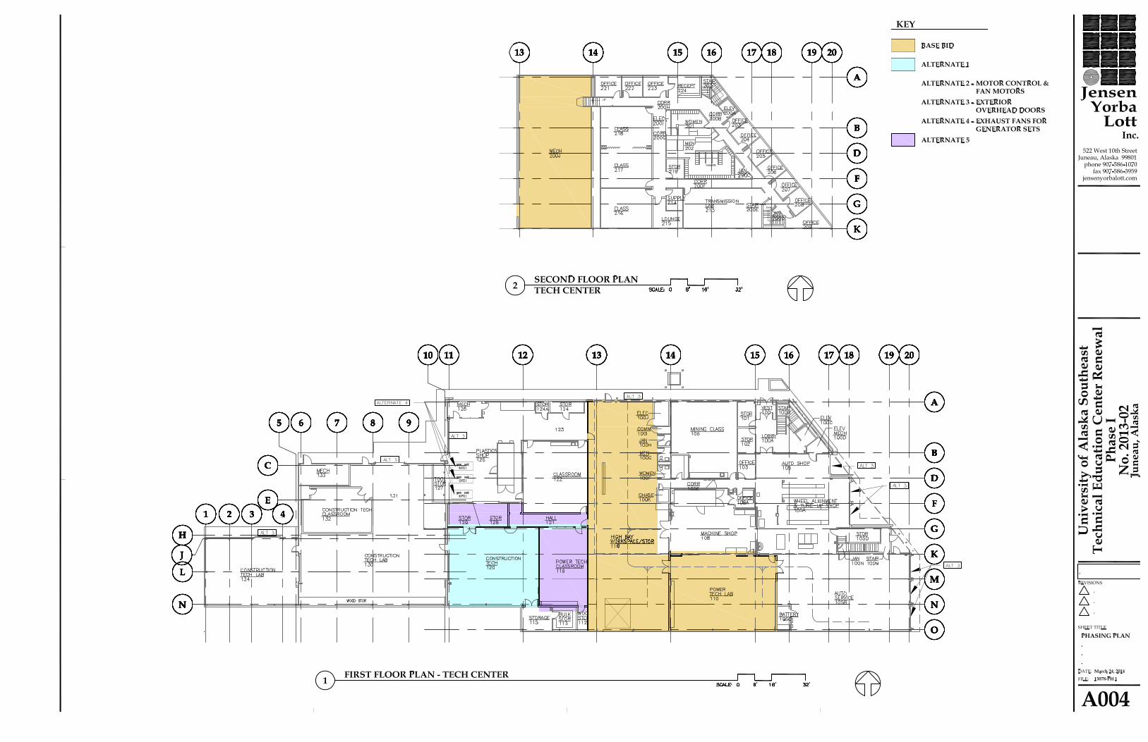
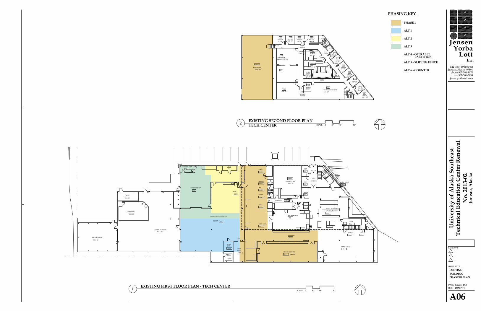
RATIONALE AND REASONING Background The project is phased: 1) to fit within available funds and 2) so that the work can be done during the summer break as the programs have no alternative locations to teach in during the academic year. Programmatic Need The Power Technology Program has had a waiting list for many years. Program capacity is limited by the available lab space. Phase I will improve and expand lab space to accommodate 50% more students, removing that constraint on program capacity. Some wood shop equipment used by the Construction Technology Program is unnecessary and can be removed. Reducing the area occupied by wood shop equipment will free up space for classrooms needed in tandem with lab space in accordance with current teaching practices. Project Scope In Phase I, the Power Technology Program will receive upgraded space, configured to meet current program requirements. The Center for Mine Training will receive an exhaust system so that generators can be run with the overhead door closed. Failing building equipment and up to 10 existing overhead doors with poor thermal properties will be replaced. Construction Technology Program equipment will be relocated. Phase 1 prepares for but does not require future phases. Future phases include replacement of additional building equipment systems and components that are nearing the end of their service lives, upgrading building common areas, and upgrading additional program spaces. Based on the current level of funding and the current construction cost estimate, the scope for this phase would be the base bid plus additive alternate #1. See plan A004. Project Impacts Conceptual and schematic design for all phases is complete. Project phasing is tailored to minimize impacts on academic programs. All programs will remain in TEC at full capacity throughout the project. Each phase will be self-contained, though building on previous phases. Variances None. Total Project Cost and Funding Sources
Funding Title Fund Account Amount Phase 1 Funding
2013 R&R capital 563138 $1,500,000 Phase 1 Project Cost $1,500,000
Annual Program and Facility Cost Projections
Program Costs Amount Salaries and benefits for new program Staff and Faculty unchanged Program Operational Costs unchanged Total Annual Program Cost Increase unchanged Facilities Costs: Maintenance & Repair unchanged Operations unchanged

SDA UAS Technical Education Center Renewal, Phase I Page 3 of 4
Annual O&M Cost will be reduced Total Annual Cost Projections will be reduced
Project Schedule – Phase 1
DESIGN Conceptual Design September, 2013 Formal Project Approval December, 2013 Schematic Design, Phase I February, 2014 Schematic Design Approval, Phase I April, 2014 Construction Documents, Phase I May, 2014
BID & AWARD - Phase 1 Advertise and Bid May, 2014 Construction Contract Award May, 2014
CONSTRUCTION Start of Construction June, 2014 Construction Complete August, 2014 Date of Beneficial Occupancy August, 2014 Warranty Period One year
Project Delivery Method Design-Bid-Build Supporting Documents
One-page Project Budget Design Narrative Document Drawings
Floor Plans Affirmation This project complies with Regents Policy, the campus master plan, and the Project Agreement.

May 4, 2014
Z:\Keith\WKG Documents Z\Projects\TEC\2013 new scope\Approvals\Schematic Ph1\TEC phase I SDA TPB-TEC phase I SDA TPB-4/28/2014-11:52 AM
UNIVERSITY OF ALASKA
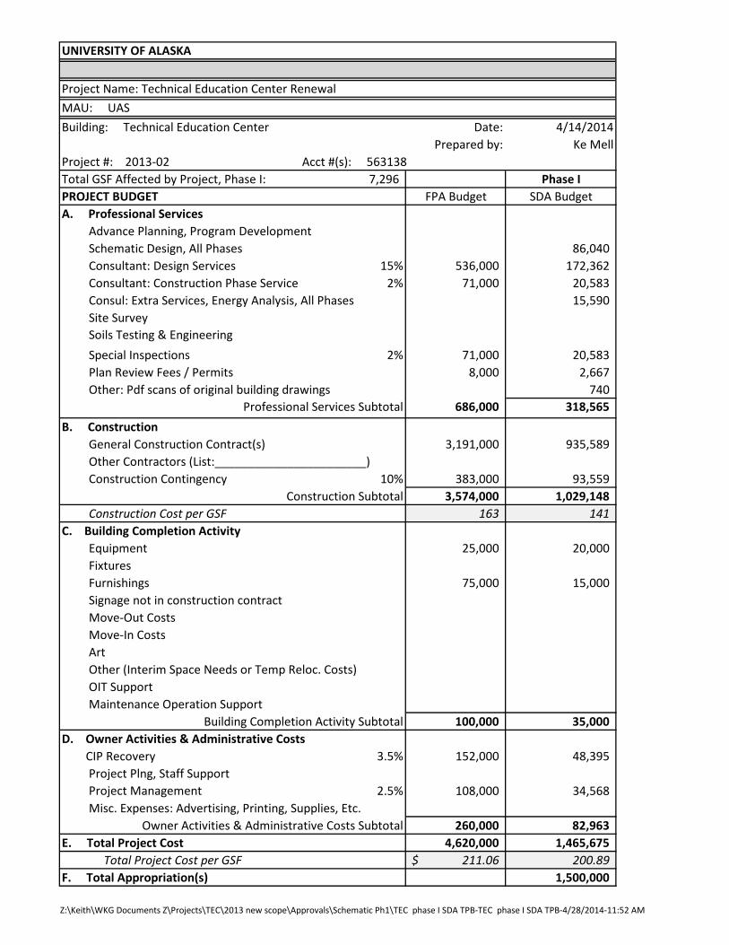
Project Name: Technical Education Center RenewalMAU: UAS
Date: 4/14/2014Prepared by: Ke Mell
Project #: 2013-02Total GSF Affected by Project, Phase I: 7,296 Phase IPROJECT BUDGET FPA Budget SDA BudgetA. Professional Services Advance Planning, Program Development Schematic Design, All Phases 86,040 Consultant: Design Services 15% 536,000 172,362 Consultant: Construction Phase Services 2% 71,000 20,583 Consul: Extra Services, Energy Analysis, All Phases 15,590 Site Survey Soils Testing & Engineering Special Inspections 2% 71,000 20,583 Plan Review Fees / Permits 8,000 2,667 Other: Pdf scans of original building drawings 740
Professional Services Subtotal 686,000 318,565 B. Construction General Construction Contract(s) 3,191,000 935,589 Other Contractors (List:_______________________) Construction Contingency 10% 383,000 93,559
Construction Subtotal 3,574,000 1,029,148 Construction Cost per GSF 163 141 C. Building Completion Activity Equipment 25,000 20,000 Fixtures Furnishings 75,000 15,000 Signage not in construction contract Move-Out Costs Move-In Costs Art Other (Interim Space Needs or Temp Reloc. Costs) OIT Support Maintenance Operation Support
Building Completion Activity Subtotal 100,000 35,000 D. Owner Activities & Administrative Costs CIP Recovery 3.5% 152,000 48,395 Project Plng, Staff Support Project Management 2.5% 108,000 34,568 Misc. Expenses: Advertising, Printing, Supplies, Etc.
Owner Activities & Administrative Costs Subtotal 260,000 82,963 E. Total Project Cost 4,620,000 1,465,675 Total Project Cost per GSF 211.06$ 200.89 F. Total Appropriation(s) 1,500,000
Building: Technical Education Center
Acct #(s): 563138

UASTechnicalEducationCenter
RenewalDesignDevelopmentNarrative
Jensen Yorba Lott, Inc.
March 24, 2014

UAS Technical Education Center Renewal Design Development Narrative Jensen Yorba Lott, Inc. Page 2
TABE OF CONTENTS
NARRATIVE ARCHITECTURAL 3 MECHANICAL 6 ELECTRICAL 14 MECHANICAL CALCULATIONS 18
UAS Technical Education Center Renewal Design Development Narrative Jensen Yorba Lott, Inc. Page 3
DESIGN DEVELOPMENT NARRATIVE
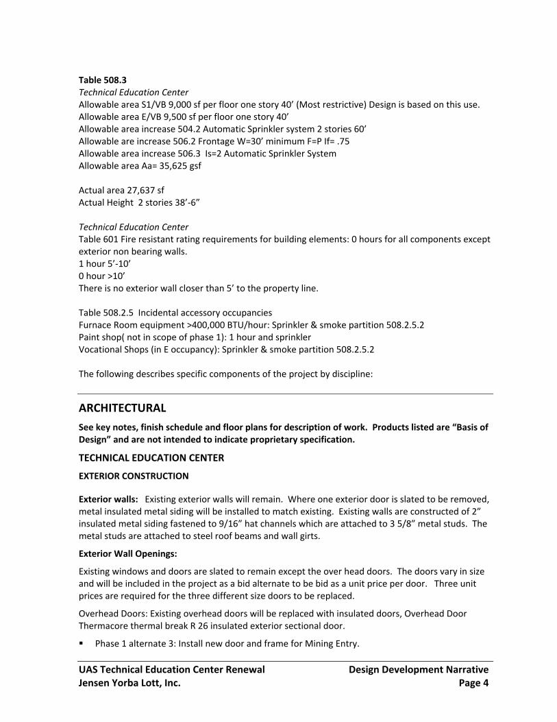
GENERAL PROJECT DESCRIPTION: The UAS Technical Education Center is comprised of two existing facilities in downtown Juneau, the Technical Center and the Welding Lab. Both are slated to undergo renovation over the span of several years, pending funding. The buildings serve the vocational education program for UAS consisting of Power Diesel Mechanic Training, Mine Training, Welding, Construction Technology and Marine Highway Education. The facility is also used by local mine companies for safety training and refresher courses. The Technical Center is a two story structure of 27,637 gsf on the first floor and 8, 861 gsf on the second floor for a total building area of 36,498gsf. The Welding lab is a two story structure with 5,163 gsf on the first floor and 727 gsf on the second floor for a total building area of 5,890 gsf. PHASING & SCHEDULE The project has been divided into 4 phases. This Design Development submittal addresses only phase 1 work. Phase 1 is scheduled to start construction May 2014 with completion by the end of August 2014. Certain designated portions of work may be allowed to be completed after the August deadline. BUDGET Funding available for phase one construction is approximately $1,000,000. The scope of the base bid work is estimated to cost $740,000. Four bid alternates have been identified to enable maximum award for the funds available. Alternate 1: Construction Technology Shop renovation and adjacent Power Technology Class are slated for construction including relocation and installation of existing shop equipment. Alternate 2: Replacement of the facility motor control center and fan motors. Alternate 3: Replacement of exterior overhead doors. Alternate 4: Installation of an exhaust fan to exhaust fumes from operation of the generator sets used for teaching in the power technology program. Phase one base bid and alternates are identified graphically on sheet A03 which shows existing areas impacted and A04 which shows the new configuration. COMPLIANCE CRITERIA: Code Data 2009 IBC: The Technology Center occupancy classification is E & S1. We have assumed an E occupancy because the building is used by the high school. If the facility was used only by the University it could be classed as a B occupancy. Because the building has an automatic sprinkler system there is little impact to areas or fire separation if classed as an E rather than a B. Construction type V B full automatic sprinkler system. The buildings are being designed under section 508.3 non separated uses which allows no separation between E and S1 occupancy.
UAS Technical Education Center Renewal Design Development Narrative Jensen Yorba Lott, Inc. Page 4
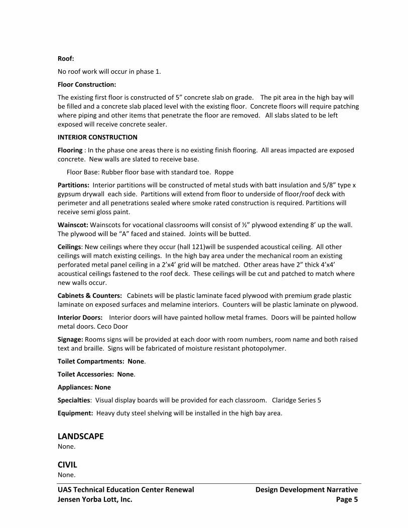
Table 508.3 Technical Education Center Allowable area S1/VB 9,000 sf per floor one story 40’ (Most restrictive) Design is based on this use. Allowable area E/VB 9,500 sf per floor one story 40’ Allowable area increase 504.2 Automatic Sprinkler system 2 stories 60’ Allowable are increase 506.2 Frontage W=30’ minimum F=P If= .75 Allowable area increase 506.3 Is=2 Automatic Sprinkler System Allowable area Aa= 35,625 gsf Actual area 27,637 sf Actual Height 2 stories 38’‐6” Technical Education Center Table 601 Fire resistant rating requirements for building elements: 0 hours for all components except exterior non bearing walls. 1 hour 5’‐10’ 0 hour >10’ There is no exterior wall closer than 5’ to the property line. Table 508.2.5 Incidental accessory occupancies Furnace Room equipment >400,000 BTU/hour: Sprinkler & smoke partition 508.2.5.2 Paint shop( not in scope of phase 1): 1 hour and sprinkler Vocational Shops (in E occupancy): Sprinkler & smoke partition 508.2.5.2 The following describes specific components of the project by discipline:
ARCHITECTURAL
See key notes, finish schedule and floor plans for description of work. Products listed are “Basis of Design” and are not intended to indicate proprietary specification.
TECHNICAL EDUCATION CENTER
EXTERIOR CONSTRUCTION
Exterior walls: Existing exterior walls will remain. Where one exterior door is slated to be removed, metal insulated metal siding will be installed to match existing. Existing walls are constructed of 2” insulated metal siding fastened to 9/16” hat channels which are attached to 3 5/8” metal studs. The metal studs are attached to steel roof beams and wall girts.
Exterior Wall Openings:
Existing windows and doors are slated to remain except the over head doors. The doors vary in size and will be included in the project as a bid alternate to be bid as a unit price per door. Three unit prices are required for the three different size doors to be replaced.
Overhead Doors: Existing overhead doors will be replaced with insulated doors, Overhead Door Thermacore thermal break R 26 insulated exterior sectional door.
Phase 1 alternate 3: Install new door and frame for Mining Entry.
UAS Technical Education Center Renewal Design Development Narrative Jensen Yorba Lott, Inc. Page 5
Roof:
No roof work will occur in phase 1.
Floor Construction:
The existing first floor is constructed of 5” concrete slab on grade. The pit area in the high bay will be filled and a concrete slab placed level with the existing floor. Concrete floors will require patching where piping and other items that penetrate the floor are removed. All slabs slated to be left exposed will receive concrete sealer.
INTERIOR CONSTRUCTION
Flooring : In the phase one areas there is no existing finish flooring. All areas impacted are exposed concrete. New walls are slated to receive base.
Floor Base: Rubber floor base with standard toe. Roppe
Partitions: Interior partitions will be constructed of metal studs with batt insulation and 5/8” type x gypsum drywall each side. Partitions will extend from floor to underside of floor/roof deck with perimeter and all penetrations sealed where smoke rated construction is required. Partitions will receive semi gloss paint.
Wainscot: Wainscots for vocational classrooms will consist of ½” plywood extending 8’ up the wall. The plywood will be “A” faced and stained. Joints will be butted.
Ceilings: New ceilings where they occur (hall 121)will be suspended acoustical ceiling. All other ceilings will match existing ceilings. In the high bay area under the mechanical room an existing perforated metal panel ceiling in a 2’x4’ grid will be matched. Other areas have 2” thick 4’x4’ acoustical ceilings fastened to the roof deck. These ceilings will be cut and patched to match where new walls occur.
Cabinets & Counters: Cabinets will be plastic laminate faced plywood with premium grade plastic laminate on exposed surfaces and melamine interiors. Counters will be plastic laminate on plywood.
Interior Doors: Interior doors will have painted hollow metal frames. Doors will be painted hollow metal doors. Ceco Door
Signage: Rooms signs will be provided at each door with room numbers, room name and both raised text and braille. Signs will be fabricated of moisture resistant photopolymer.
Toilet Compartments: None.
Toilet Accessories: None.
Appliances: None
Specialties: Visual display boards will be provided for each classroom. Claridge Series 5
Equipment: Heavy duty steel shelving will be installed in the high bay area.
LANDSCAPE None.
CIVIL None.
UAS Technical Education Center Renewal Design Development Narrative Jensen Yorba Lott, Inc. Page 6
STRUCTURAL None.
MECHANICAL
DIVISION 22 & 23 ‐ MECHANICAL SYSTEMS Work will consist of renovating the mechanical systems of the UAS Technical Education Center for phase 1 of a multi‐phase renovation (phase 1‐4). The mechanical design narrative is organized according to base bid work and four alternates as selected by the Owner. Select mechanical system upgrades are slated to be completed under each portion of work described. See end of report for summary of existing systems.
The BASE BID scope of work consists of: reconfiguration of supply and return air ductwork and compressed air piping in the new 110‐Power Tech Lab layout; installation of new return air and motor fume exhaust ductwork for 110‐Power Tech Lab; removal of abandoned exhaust air ductwork routed through the 110‐Power Tech Lab area connected to EF‐2A; removal of exhaust air ductwork from the 109D‐Auto Service Area; installation of new general duty exhaust fan EF‐5 and ductwork and a self‐contained eyewash station in 116‐High Bay area; installation of new motor fume exhaust fan MFEF‐3 in 200U1‐Mechanical room and ductwork in 116‐High Bay; reconfiguration of SF‐2 return air duct in mechanical room and cleaning of all related SF‐2 supply and return air duct systems; installation of new and relocated compressed air hose reels in 116‐High Bay; and removal of exhaust fan EF‐2B and all connected ductwork from existing 133‐Battery room.
The ALTERNATE 1 scope of work consists of: reconfiguration of the saw dust collection system ductwork in the new 120‐Construction Tech and 121‐Hall Areas; and reconfiguration of the supply and return air ductwork in new 119‐Power Tech Class area.
The ALTERNATE 2 scope of work consists of: replacement of fan motors SF‐1, RF‐1, SF‐2, RF‐2A, RF‐2B, RF‐2C with premium efficiency motors; installation of new fan motor fume exhaust fan MEFE‐3; and replacement of fan MFEF‐2B with MFEF‐5 in 200U1‐Mechanical room.
The ALTERNATE 3 scope of work is part of architectural. No mechanical work.
The ALTERNATE 4 scope of work consists of the installation of a generator motor fume exhaust fan MEFE‐4 in the new 130‐Heavy Equipment Simulator room.
DESIGN CRITERIA The mechanical systems will be designed and constructed in accordance with the following codes:
2009 International Building Code
2009 International Mechanical Code
2009 Uniform Plumbing Code
2009 International Fire Code
National Fire Protection Association
ASHRAE – American Society of Heating, Refrigeration, and Air‐conditioning Engineers
ASHRAE Standard 62.1‐2007: Ventilation for Acceptable Indoor Air Quality.
City and Borough of Juneau Code Modifications
ACGIH (IV) – American Conference of Governmental Industrial Hygienists; 2010.
UAS Technical Education Center Renewal Design Development Narrative Jensen Yorba Lott, Inc. Page 7
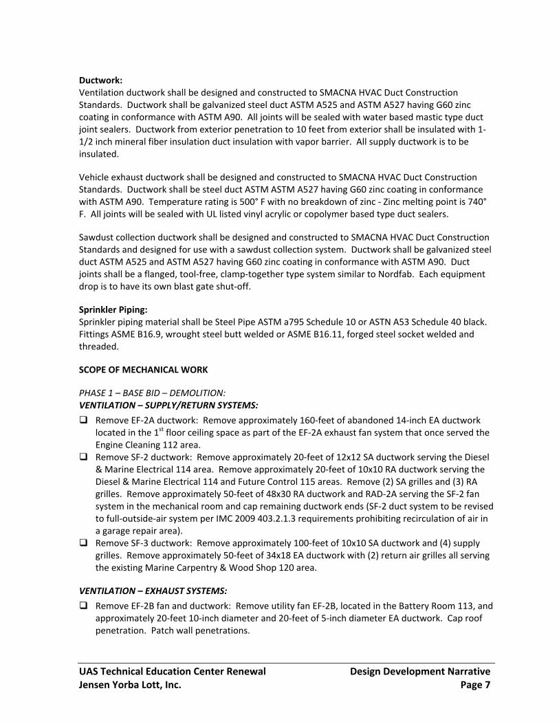
Ductwork: Ventilation ductwork shall be designed and constructed to SMACNA HVAC Duct Construction Standards. Ductwork shall be galvanized steel duct ASTM A525 and ASTM A527 having G60 zinc coating in conformance with ASTM A90. All joints will be sealed with water based mastic type duct joint sealers. Ductwork from exterior penetration to 10 feet from exterior shall be insulated with 1‐1/2 inch mineral fiber insulation duct insulation with vapor barrier. All supply ductwork is to be insulated.
Vehicle exhaust ductwork shall be designed and constructed to SMACNA HVAC Duct Construction Standards. Ductwork shall be steel duct ASTM ASTM A527 having G60 zinc coating in conformance with ASTM A90. Temperature rating is 500° F with no breakdown of zinc ‐ Zinc melting point is 740° F. All joints will be sealed with UL listed vinyl acrylic or copolymer based type duct sealers.
Sawdust collection ductwork shall be designed and constructed to SMACNA HVAC Duct Construction Standards and designed for use with a sawdust collection system. Ductwork shall be galvanized steel duct ASTM A525 and ASTM A527 having G60 zinc coating in conformance with ASTM A90. Duct joints shall be a flanged, tool‐free, clamp‐together type system similar to Nordfab. Each equipment drop is to have its own blast gate shut‐off.
Sprinkler Piping: Sprinkler piping material shall be Steel Pipe ASTM a795 Schedule 10 or ASTN A53 Schedule 40 black. Fittings ASME B16.9, wrought steel butt welded or ASME B16.11, forged steel socket welded and threaded.
SCOPE OF MECHANICAL WORK
PHASE 1 – BASE BID – DEMOLITION: VENTILATION – SUPPLY/RETURN SYSTEMS:
Remove EF‐2A ductwork: Remove approximately 160‐feet of abandoned 14‐inch EA ductwork located in the 1st floor ceiling space as part of the EF‐2A exhaust fan system that once served the Engine Cleaning 112 area.
Remove SF‐2 ductwork: Remove approximately 20‐feet of 12x12 SA ductwork serving the Diesel & Marine Electrical 114 area. Remove approximately 20‐feet of 10x10 RA ductwork serving the Diesel & Marine Electrical 114 and Future Control 115 areas. Remove (2) SA grilles and (3) RA grilles. Remove approximately 50‐feet of 48x30 RA ductwork and RAD‐2A serving the SF‐2 fan system in the mechanical room and cap remaining ductwork ends (SF‐2 duct system to be revised to full‐outside‐air system per IMC 2009 403.2.1.3 requirements prohibiting recirculation of air in a garage repair area).
Remove SF‐3 ductwork: Remove approximately 100‐feet of 10x10 SA ductwork and (4) supply grilles. Remove approximately 50‐feet of 34x18 EA ductwork with (2) return air grilles all serving the existing Marine Carpentry & Wood Shop 120 area.
VENTILATION – EXHAUST SYSTEMS:
Remove EF‐2B fan and ductwork: Remove utility fan EF‐2B, located in the Battery Room 113, and approximately 20‐feet 10‐inch diameter and 20‐feet of 5‐inch diameter EA ductwork. Cap roof penetration. Patch wall penetrations.

UAS Technical Education Center Renewal Design Development Narrative Jensen Yorba Lott, Inc. Page 8
PLUMBING – SPECIAL PIPING:
Relocate hose reels and remove air piping: Remove approximately (50) feet of ¾‐inch air piping and remove and store (5) hose reels and associated branch piping located in the Diesel & Marine Electrical 114 area. Store hose reels for reinstallation.
PLUMBING – SPRINKLER PIPING:
Modify sprinkler system: Sprinkler heads and branch piping will need to be renovated to match the new layout. Minor modifications to existing system will be required to ensure coverage of the remodeled areas.
PHASE 1 – BASE BID – NEW WORK: VENTILATION – SUPPLY/RETURN SYSTEMS:
Install SF‐2 ductwork: Install approximately 90‐feet of 12x12 SA ductwork with (2) supply grilles. Install approximately 70‐feet of 14x12 EA ductwork with (2) exhaust grilles all to serve new Power Tech Lab 110 layout as shown on architectural. See schedule on mechanical drawings for grille sizes.
Install SF‐3 ductwork: Install approximately 60‐feet of 12x12 SA ductwork with (4) supply grilles serving the Power Tech Classroom 119 area. Install approximately 120‐feet of 18x18 RA ductwork with (2) exhaust grilles serving new Power Tech Classroom 119. Install approximately 100‐feet of 18x18 RA ductwork with (2) exhaust grilles serving the new layout adjacent to both the new Hall 121 and existing Heavy Equipment Simulator 130 areas as shown on architectural. See schedule on mechanical drawings for grille sizes.
Install EF‐5 fan and ductwork: Install new general duty exhaust fan EF‐5 on exterior West wall of new Paint Spray Booth 118. Install approximately 120‐feet of 12‐inch diameter EA ductwork with (2) EA grilles in the ceiling space to serve general use for High Bay Workspace/Storage 116. Fan to be controlled by wall switch.
Install MFEF‐3 fan and ductwork: Install new motor fume exhaust fan MFEF‐3 in Mechanical Room 219. Install approximately 80‐feet of 6‐inch diameter EA ductwork along with (4) equipment drops with 15‐feet of 4‐inch retractable flexible duct for each drop. New exhaust system is to serve the new High Bay 116 area.
Duct cleaning: Clean interior of all supply/return ducts, and all diffusers/grilles in project area only for the first floor. Clean interior of SF‐2 fan system and interior of all SF‐2 related supply/return ducts in the mechanical room.
PLUMBING – DOMESTIC PLUMBING:
Install emergency eyewash station: Install new self‐contained, wall mounted, emergency eye wash station in new 116‐High Bay.
PLUMBING – SPRINKLER PIPING:
Revise sprinkler piping: Sprinkler designer is to verify that all areas are up to current code and configuration. Assume adding (5) sprinkler heads along moved wall to connecting branch piping for this new work in the 116‐High Bay and replacing approximately (45) sprinkler heads throughout the renovated area with upright pendent type, glass bulb type, sprinkler heads in existing sprinkler piping.

UAS Technical Education Center Renewal Design Development Narrative Jensen Yorba Lott, Inc. Page 9
CONTROLS:
Install DDC controls: Upgrade respective fan system controls and room thermostats.
PHASE 1 BASE BID FAN SCHEDULE
1. EF‐5 2800 cfm 1 hp/480V/1 ph 2. MFEF‐3 1600 cfm 5 hp/480V/3ph, Explosion Proof 3. MFEF‐5 1200 cfm 5 hp/480V/3ph, Explosion Proof
PHASE 1 – ALTERNATE 1 – DEMOLITION: VENTILATION – EXHAUST SYSTEMS:
Remove EF‐3 fan: Remove utility exhaust fan EF‐3 located in Mechanical Room 219. Remove approximately 50‐feet of existing EA and (2) EA grilles located in Plastics Shop 122.
Remove dust collector ductwork: Remove approximately 250‐feet of EA ductwork and drops for (8) pieces of equipment located in the Carpentry/Wood Shop 125 area.
PLUMBING – SPRINKLER PIPING:
Modify sprinkler system: Sprinkler heads and branch piping will need to be renovated to match the new layout. Minor modifications to existing system will be required to ensure coverage of the remodeled areas.
PHASE 1 – ALTERNATE 1 – NEW WORK: VENTILATION – SUPPLY/RETURN SYSTEMS:
Revise dust collector ductwork: Revise EA ductwork for (10) pieces of equipment located in the new Construction Tech 120 area. Install approximately 230‐feet of new EA ductwork in ceiling space with (11) equipment drops for each equipment station and (2) drops for floor sweeps. Provide flexible connections approximately 8‐feet for piece of equipment. Average of 4‐inches for each drop.
Fan and duct cleaning: Clean interior of all fans, all exhaust ducts, and all diffusers/grilles in project area only.
PLUMBING – SPRINKLER PIPING:
Revise sprinkler piping: Sprinkler designer is to verify that all areas are up to current code and configuration. Replace approximately (40) sprinkler heads throughout the renovated area with upright pendent type, glass bulb type, sprinkler heads in existing sprinkler piping.
PHASE 1 – ALTERNATE 2 – DEMOLITION: VENTILATION – SUPPLY/RETURN SYSTEMS:
Remove SF‐1, RF‐1 fan motors: Remove supply fan SF‐1 and return fan RF‐1 motors in Mechanical Room 219. Ventilation system has (7) dual plenum heating zones to remain existing in this phase.
Remove SF‐2, RF‐2A, RF‐2B, RF‐2C fan motors: Remove supply fan SF‐2 and return fans RF‐2A & RF‐2B & RF‐2C motors in Mechanical Room 219. Ventilation system has (9) dual plenum heating zones.

UAS Technical Education Center Renewal Design Development Narrative Jensen Yorba Lott, Inc. Page 10
Remove dampers and actuators: Remove (18) control dampers and actuators: The majority of the ductwork is to remain unmodified.
Remove SF‐3, RF‐3A, RF‐3B fan motors: Remove supply fan SF‐3 and return fan RF3A & RF‐3B motors in Mechanical Room 219. Ventilation system has (2) dual plenum heating zones. The ductwork routing is to remain unmodified.
Remove dampers and actuators: Remove (4) control dampers and actuators. Refurbish air handling unit: Refurbishment to include the following: Replace air handling unit
bearings (acceptable bearing manufacturers Timken, Fafnir, SKF); replace air handling unit fan /motor sheaves (acceptable sheave manufacturers Browning, Woods, Maurey ); replace fan belts; clean all dirt from individual fan blades; clean all dirt and grease from fan housing and interior of AHU plenum; clean interior of ductwork; clean diffusers.
Duct cleaning: Clean interior of all supply/return ducts, and all diffusers/grilles in project area only.
VENTILATION – EXHAUST SYSTEMS:
Remove EF‐2A ductwork: Disconnect 14‐inch diameter EA ductwork connected to exhaust fan EF‐2A located in Mechanical Room 219. Remove approximately 30‐feet of EA ductwork serving Engine Cleaning 112.
Remove MFEF‐2B fan: Remove motor fume exhaust fan MFEF‐2B. Existing ductwork is to remain at the Diesel & Marine Electrical 114 area. Disconnect and abandon 7‐inch diameter ductwork connected to MFEF‐2B in Mechanical Room 219 and serving Small Engines 133.
PLUMBING – SPRINKLER PIPING:
Modify sprinkler system: Sprinkler heads and branch piping will need to be renovated to match the new layout. Minor modifications to existing system will be required to ensure coverage of the new areas.
PHASE 1 – ALTERNATE 2 – NEW WORK: VENTILATION – SUPPLY/RETURN SYSTEMS:
Install SF‐1, RF‐1 fan motors: Replace supply fan SF‐1 and return fan RF‐1 motors in Mechanical Room 219 with premium efficiency motors. See schedule below for all fan specifications.
Replace SF‐2, RF‐2A, RF‐2B, RF‐2C fan motors: Replace supply fan SF‐2 and return fan RF‐2A & RF‐2B & RF‐2C motors in Mechanical Room 219 with premium efficiency motors.
Replace dampers and actuators: Replace (18) control dampers and actuators. Replace SF‐3, RF‐3A, RF‐3B fan motors: Replace supply fan SF‐3 and return fan RF3A & RF‐3B
motors in Mechanical Room 219 with premium efficiency motors.
Replace dampers and actuators: Replace (4) control dampers and actuators. Refurbish air handling unit: Refurbishment to include the following: Replace air handling unit
bearings (acceptable bearing manufacturers Timken, Fafnir, SKF); replace air handling unit fan /motor sheaves (acceptable sheave manufacturers Browning, Woods, Maurey ); replace fan belts; clean all dirt from individual fan scroll blades; clean all dirt and grease from fan housing and interior of AHU plenum; clean interior of ductwork; clean diffusers.
Duct cleaning: Clean interior of all supply/return ducts, and all diffusers/grilles in project area.
UAS Technical Education Center Renewal Design Development Narrative Jensen Yorba Lott, Inc. Page 11
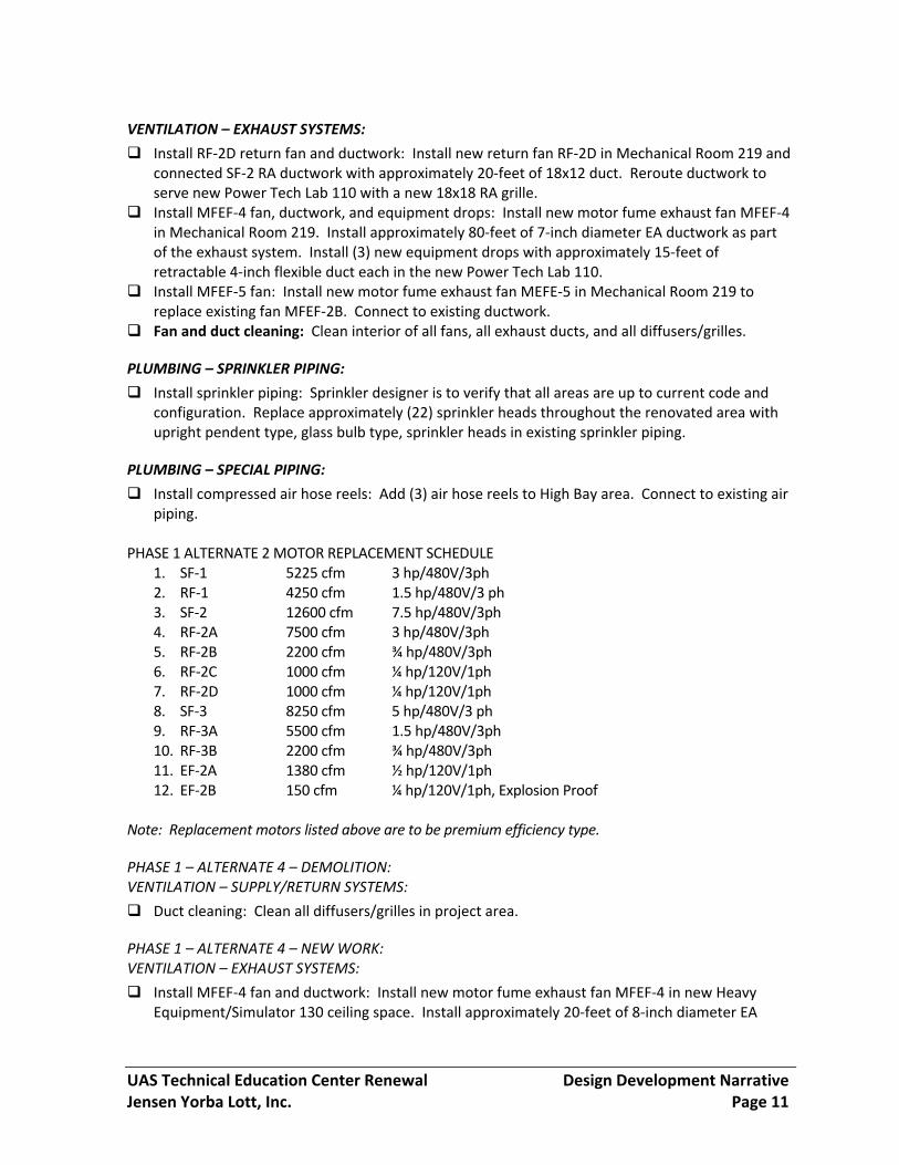
VENTILATION – EXHAUST SYSTEMS:
Install RF‐2D return fan and ductwork: Install new return fan RF‐2D in Mechanical Room 219 and connected SF‐2 RA ductwork with approximately 20‐feet of 18x12 duct. Reroute ductwork to serve new Power Tech Lab 110 with a new 18x18 RA grille.
Install MFEF‐4 fan, ductwork, and equipment drops: Install new motor fume exhaust fan MFEF‐4 in Mechanical Room 219. Install approximately 80‐feet of 7‐inch diameter EA ductwork as part of the exhaust system. Install (3) new equipment drops with approximately 15‐feet of retractable 4‐inch flexible duct each in the new Power Tech Lab 110.
Install MFEF‐5 fan: Install new motor fume exhaust fan MEFE‐5 in Mechanical Room 219 to replace existing fan MFEF‐2B. Connect to existing ductwork.
Fan and duct cleaning: Clean interior of all fans, all exhaust ducts, and all diffusers/grilles.
PLUMBING – SPRINKLER PIPING:
Install sprinkler piping: Sprinkler designer is to verify that all areas are up to current code and configuration. Replace approximately (22) sprinkler heads throughout the renovated area with upright pendent type, glass bulb type, sprinkler heads in existing sprinkler piping.
PLUMBING – SPECIAL PIPING:
Install compressed air hose reels: Add (3) air hose reels to High Bay area. Connect to existing air piping.
PHASE 1 ALTERNATE 2 MOTOR REPLACEMENT SCHEDULE
1. SF‐1 5225 cfm 3 hp/480V/3ph 2. RF‐1 4250 cfm 1.5 hp/480V/3 ph 3. SF‐2 12600 cfm 7.5 hp/480V/3ph 4. RF‐2A 7500 cfm 3 hp/480V/3ph 5. RF‐2B 2200 cfm ¾ hp/480V/3ph 6. RF‐2C 1000 cfm ¼ hp/120V/1ph 7. RF‐2D 1000 cfm ¼ hp/120V/1ph 8. SF‐3 8250 cfm 5 hp/480V/3 ph 9. RF‐3A 5500 cfm 1.5 hp/480V/3ph 10. RF‐3B 2200 cfm ¾ hp/480V/3ph 11. EF‐2A 1380 cfm ½ hp/120V/1ph 12. EF‐2B 150 cfm ¼ hp/120V/1ph, Explosion Proof
Note: Replacement motors listed above are to be premium efficiency type.
PHASE 1 – ALTERNATE 4 – DEMOLITION: VENTILATION – SUPPLY/RETURN SYSTEMS:
Duct cleaning: Clean all diffusers/grilles in project area.
PHASE 1 – ALTERNATE 4 – NEW WORK: VENTILATION – EXHAUST SYSTEMS:
Install MFEF‐4 fan and ductwork: Install new motor fume exhaust fan MFEF‐4 in new Heavy Equipment/Simulator 130 ceiling space. Install approximately 20‐feet of 8‐inch diameter EA
UAS Technical Education Center Renewal Design Development Narrative Jensen Yorba Lott, Inc. Page 12
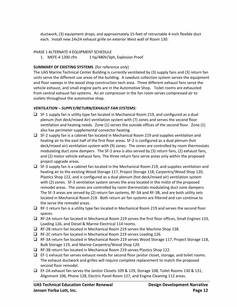
ductwork, (3) equipment drops, and approximately 15‐feet of retractable 4‐inch flexible duct each. Install new 24x24 exhaust grille on exterior West wall of Room 130.
PHASE 1 ALTERNATE 4 EQUIPMENT SCHEDULE 1. MEFE‐4 1200 cfm 1 hp/480V/3ph, Explosion Proof
SUMMARY OF EXISTING SYSTEMS (for reference only) The UAS Marine Technical Center Building is currently ventilated by (3) supply fans and (3) return fan units serve the different use areas of the building. A sawdust collection system serves the equipment and floor sweeps in the wood shop construction tech area. Three different exhaust fans serve the vehicle exhaust, and small engine parts are in the Automotive Shop. Toilet rooms are exhausted from central exhaust fan systems. An air compressor in the fan room serves compressed air to outlets throughout the automotive shop.
VENTILATION – SUPPLY/RETURN/EXHAUST FAN SYSTEMS:
SF‐1 supply fan is utility type fan located in Mechanical Room 219, and configured as a dual plenum (hot deck/mixed Air) ventilation system with (7) zones and serves the second floor ventilation and heating needs. Zone (1) serves the outside offices of the second floor. Zone (1) also has perimeter supplemental convector heating.
SF‐2 supply fan is a cabinet fan located in Mechanical Room 219 and supplies ventilation and heating air to the east half of the first floor areas. SF‐2 is configured as a dual plenum (hot deck/mixed air) ventilation system with (9) zones. The zones are controlled by room thermostats modulating duct zone dampers. The SF‐2 area is also served by (3) return fans, (2) exhaust fans, and (2) motor vehicle exhaust fans. The three return fans serve areas only within the proposed project upgrade areas.
SF‐3 supply fan is a cabinet fan located in the Mechanical Room 219, and supplies ventilation and heating air to the existing Wood Storage 117, Project Storage 118, Carpentry/Wood Shop 120, Plastics Shop 122, and is configured as a dual plenum (hot deck/mixed air) ventilation system with (2) zones. SF‐3 ventilation system serves the area located in the midst of the proposed remodel areas. The zones are controlled by room thermostats modulating duct zone dampers. The SF‐3 areas are served by (2) return fan systems, RF‐3A and RF‐3B, and are both utility sets located in Mechanical Room 219. Both return air fan systems are filtered and can continue to the serve the remodel areas.
RF‐1 return fan is a utility type fan located in Mechanical Room 219 and serves the second floor spaces.
RF‐2A return fan located in Mechanical Room 219 serves the first floor offices, Small Engines 133, Loading 126, and Diesel & Marine Electrical 114 rooms.
RF‐2B return fan located in Mechanical Room 219 serves the Machine Shop 138. RF‐2C return fan located in Mechanical Room 219 serves Loading 126. RF‐3A return fan located in Mechanical Room 219 serves Wood Storage 117, Project Storage 118,
Bulk Storage 119, and Marine Carpentry/Wood Shop 120. RF‐3B return fan located in Mechanical Room 219 serves Plastics Shop 122. EF‐1 exhaust fan serves exhaust needs for second floor janitor closet, storage, and toilet rooms.
The exhaust ductwork and grilles will require complete replacement to match the proposed second floor remodel.
EF‐2A exhaust fan serves the Janitor Closets 109 & 129, Storage 108, Toilet Rooms 130 & 131, Alignment 106, Phone 128, Electric Panel Room 127, and Engine Cleaning 112 areas.

UAS Technical Education Center Renewal Design Development Narrative Jensen Yorba Lott, Inc. Page 13
EF‐2B exhaust fan serves the Battery Room 113. EF‐3 serves a small amount of exhaust air as part of the SF‐3 system area in the Plastic Shop 122. EF‐4 serves to exhaust air from Mechanical Room 219.
MFEF‐2A Motor Fume Exhaust Fan, located in Mechanical 219, serves motor fume exhaust ports in Tune‐Up 107 and Service Stalls 111.
MFEF‐2B Motor Fume Exhaust Fan, located in Mechanical 219, serves motor fume exhaust ports in Diesel & Marine Electrical 1114 and Small Engines 133.
EXISTING SUPPLY/RETURN/EXHAUST FAN SCHEDULE 1. SF‐1 5225 cfm 3 hp/480V/3ph 2. SF‐2 12600 cfm 7.5 hp/480V/3ph 3. SF‐3 8250 cfm 5 hp/480V/3 ph 4. RF‐1 4250 cfm 1.5 hp/480V/3 ph 5. RF‐2A 7500 cfm 3 hp/480V/3ph 6. RF‐2B 2200 cfm ¾ hp/408V/3ph 7. RF‐2C 1000 cfm ¼ hp/120V/1ph 8. RF‐3A 5500 cfm 1.5 hp/480V/3ph 9. RF‐3B 2200 cfm ¾ hp/480V/3ph 10. EF‐1 300 cfm ½ hp/120V/1ph 11. EF‐2A 1380 cfm ½ hp/120V/1ph 12. EF‐2B 150 cfm ¼ hp/120V/1ph, Explosion Proof 13. EF‐3 300 cfm ¼ hp/120V/1ph 14. EF‐4 1000 cfm ¼ hp/120V/1ph 15. MFEF‐2A 1400 cfm 2 hp/480V/3ph, Explosion Proof 16. MFEF‐2B 1100 cfm 1 hp/480V/3ph, Explosion Proof
VENTILATION – DUST COLLECTION SYSTEM:
The existing sawdust collection system is in fair condition.
Schedule of existing equipment is as follows: 1. Sawdust Collector Fan 11,000 cfm 40 HP/460V/3PH 2. Sawdust Collector Shaker ¾ HP/208V/1ph
PLUMBING – SPRINKLER PIPING: Sprinkler protection for the first floor and second floors of the building are being provided by a wet sprinkler system for the interior of building in accordance with NFPA 13. TEC AIR COMPRESSOR:
The original air compressor, located in Mechanical Room 219, is used extensively throughout the facility. Air compressor is in fair condition. An additional air compressor, located in Battery Room 113, is used by the Service Stalls 111 area. Air compressor is in fair condition. EXISTING COMPRESSED AIR EQUIPMENT SCHEDULE

UAS Technical Education Center Renewal Design Development Narrative Jensen Yorba Lott, Inc. Page 14
1. AC‐1 200 gal. 50HP/480V/3PH 2. Air Dryer 1/5 HP/120V/1PH 3. Sprinkler Compressor 1.5HP/460V/3PH
TEC BUILDING CONTROLS: The building control system was originally pneumatically controlled. In the 1990’s a partial upgrade to DDC was done that replaced room thermostats with DDC type and installed controllers for operation of systems. Much of the sensors and all valve and damper actuators were not replaced and are still pneumatic.
ELECTRICAL Existing Systems Utility Services and Distribution Equipment Utility power for the Technology Center and Welding Lab originates at a pole on Egan Drive. The primary feeder is routed through a vault in the road to the Welding Lab pad mounted transformer. The Welding Lab pad mounted transformer loop feeds the Technology Center transformer. The primary feeders are in good condition. The pad mounted transformers have some surface rust on the enclosures but otherwise are in good condition. The Technology Center pad mounted utility transformer is located on the north side of the building. The pad mounted transformer feeds a main switchboard in Electrical 108. The switchboard is rated 1000 amperes, 277/480 volt, 3‐phase, 4‐wire. The switchboard main circuit breaker has a 900 ampere trip rating. The switchboard feeds panelboards, a motor control center, the elevator, emergency lighting inverters, and the sawdust collector. The panelboards are typically grouped with a 277/480 volt section, dry‐type transformer, and 120/208 volt section placed in the same location. Some of the transformers were remote mounted due to space limitations. All of the service and distribution equipment is from the original construction and due for replacement. Lighting Systems Lighting in the Technology Center consists mostly of low‐bay metal halide fixtures and fluorescent fixtures in various configurations. The fluorescent fixtures utilize T12 lamps, except in the construction technology area and the power technology lab where fixtures with T8 lamps have been installed. The lighting is controlled by low voltage switches wired through relays mounted in enclosures near the panelboards. Emergency power for egress lighting is provided by a central inverter system. The lighting branch circuits are configured 277 volt. The illumination levels in many areas are inadequate. The metal halide fixtures are failing and provide undesirable color rendering characteristics. The fluorescent fixtures are inefficient. The low voltage control system is failing. The central inverter systems appear to be operational, but the egress lighting system does not comply with current codes. Overall, the lighting systems are in poor condition and no longer maintainable. Communications A 50‐pair outside plant telephone cable enters the Technology Center in Communications 107A. The space also houses the primary protection, termination, and cross‐connect blocks. A 25‐pair telephone trunk cable is routed in a 4‐inch underground conduit from the Technology Center to the

UAS Technical Education Center Renewal Design Development Narrative Jensen Yorba Lott, Inc. Page 15
Welding Lab. An open data rack, located in a closet on the second floor of the Technology Center, supports data patch panels, network switches, and auxiliary components. The Technology Center was retrofitted with a voice‐over‐IP telephone system, likely in the last 10‐years. The Technology Center lacks a reliable data infrastructure required to support current administrative and teaching technologies. Fire Alarm The Technology Center fire alarm system was replaced in 2011 and is in excellent condition. Security The main exterior doors of the Technology Center are secured with an electronic access system using proximity cards. The interior side of the doors has a push‐to‐exit button with an infrared sensor to automatically un‐latch the door. The control panel and power supply are located in Electrical 108. The system is in working order and appears to be in good condition. We do not anticipate any work with the security system, unless system enhancements are desired by the Owner. Electrical Improvements Base Bid Utility Services and Distribution Equipment
Demolish panels H1D and L1D. Demolish associated feeders and dry‐type transformer.
Provide new panels H1D and L1D in new location as indicated.
Provide new 150/3 circuit breaker in existing main switchboard for panel H1D feeder.
Branch Circuits
Provide new branch circuits for all new devices and lighting. Reconnect existing loads to new
panelboards as indicated.
Mechanical Equipment
Fans RF‐2B and RF‐2C shall be replaced by the mechanical contractor. Coordinate
reconnection to existing branch circuits.
Provide new connections and controls for fans EF‐5 and MFEF‐3.
Lighting Systems
Provide new light fixtures in Power Tech Lab 110 and High Bay Workspace 116.
Provide low voltage control panel LCP D.
Wiring Devices
Provide new wiring devices in Power Tech Lab 110 and High Bay Workspace 116.
Communications
Provide new data rack with patch panel in Communications 107A. Provide backbone cable
from Communications 107A to the existing second floor data rack for connection to existing
network.

UAS Technical Education Center Renewal Design Development Narrative Jensen Yorba Lott, Inc. Page 16
Provide new data outlets as indicated. Provide 1” conduit from each data drop to
Communications 107A for routing cables.
Fire Alarm
Relocate existing initiating and notification devices to coordinate with the new space
configurations. Re‐connect system devices to the existing fire alarm control panel. Provide
new cabling as required.
Alternate 1 Utility Services and Distribution Equipment
Replace the main switchboard.
Replace panels H1A, H1B, H1C, H1E, H1F, H2A, H1X, L1A, L1B, L1C, L1E, and L1F. Replace
feeders and dry‐type transformers.
Branch Circuits
Provide new branch circuits for all new devices and lighting.
Mechanical Equipment
Fan RF‐3A shall be replaced by the mechanical contractor. Coordinate reconnection to
existing branch circuits.
Revise connections and control system for dust collector.
Lighting Systems
Provide new light fixtures in Power Tech Classroom 119, Construction Tech 120, Wood
Storage 125A, and Storage 129.
Provide low voltage lighting control panel LCP E.
Wiring Devices
Provide new wiring devices in Power Tech Classroom 119, Construction Tech 120, Wood
Storage 125A, and Storage 129.
Provide new wiring devices on the east wall of Mining Training Classroom 123.
Re‐circuit existing devices in Mining Training 123, and Heavy Equipment Simulator 130 to
Panelboard L1F.
Communications
Provide new data outlets in Power Tech Classroom 119 and Construction Tech 120.
Horizontal cables shall terminate in Communications 107A.
Fire Alarm
Relocate existing initiating and notification devices to coordinate with the new space
configurations. Re‐connect system devices to the existing fire alarm control panel. Provide
new cabling as required.

UAS Technical Education Center Renewal Design Development Narrative Jensen Yorba Lott, Inc. Page 17
Alternate 2 Utility Services and Distribution Equipment
Replace the motor control center in Mechanical 200U1. Replace panelboard L2B and
transformer L2B.
Mechanical Equipment
Fan SF‐1, SF‐2, SF‐3, RF‐1, and RF‐2A shall be replaced by the mechanical contractor.
Coordinate reconnection to existing branch circuits.
Alternate 3 Branch Circuits
The exterior overhead doors shall be replaced by the general contractor. Connect new doors
to existing branch circuits. Provide connection to new control stations.
Alternate 4 Mechanical Equipment
Fan RF‐3B shall be replaced by the mechanical contractor. Coordinate reconnection to
existing branch circuits.
Provide new connection and controls for fans MFEF‐4 and MFEF‐5.
END OF NARRATIVE
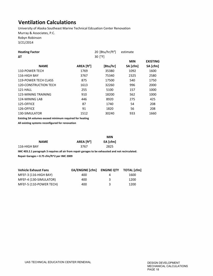
Ventilation CalculationsUniversity of Alaska Southeast Marine Technical Edcuation Center RenovationMurray & Associates, P.C.Robyn Robinson3/21/2014
Heating Factor 20 [Btu/hr/ft²] estimate∆T 30 [°F]
MIN EXISTINGNAME AREA [ft²] [Btu/hr] SA [cfm] SA [cfm]
110-POWER TECH 1769 35380 1092 1600116-HIGH BAY 3767 75340 2325 2580119-POWER TECH CLASS 875 17500 540 1750120-CONSTRUCTION TECH 1613 32260 996 2000121-HALL 255 5100 157 1000123-MINING TRAINING 910 18200 562 1000124-MINING LAB 446 8920 275 425125-OFFICE 87 1740 54 208126-OFFICE 91 1820 56 208130-SIMULATOR 1512 30240 933 1660Existing SA volumes exceed minimum required for heating
All existing systems reconfigured for renovation
MINNAME AREA [ft²] EA [cfm]
116-HIGH BAY 3767 2825IMC 403.2.1 paragraph 3 requires all air from repair garages to be exhausted and not recirculated.
Repair Garages = 0.75 cfm/ft^2 per IMC 2009
Vehicle Exhaust Fans EA/ENGINE [cfm] ENGINE QTY TOTAL [cfm]MFEF-3 (116-HIGH BAY) 400 4 1600MFEF-4 (130-SIMULATOR) 400 3 1200MFEF-5 (110-POWER TECH) 400 3 1200
UAS TECHNICAL EDUCATION CENTER RENEWAL DESIGN DEVELOPMENT MECHANICAL CALCULATIONS PAGE 18
91 SF.OFFICE
208
91 SF.OFFICE
207
206
91 SF.OFFICE
205
91 SF.OFFICE
OFFICE
224
200W1
200M1200U1
211JAN
ELEV.
91 SF.OFFICE
204
DWN
203
52 SF.
300 SF
CORR 4
625 SF
TRANSMISSION LAB
JAN
233
53 SF
OFFICE
111 SF.
223
CORR 1230 SF
148 SF
RECEPT.
WOMEN
217 SF
MEN561 SF
170 SF
213
252 SF
CORR 2
231
STORAGE70 SF
214
SUPPLY88 SF
215
218
OFFICE92 SF
222221
UP
OFFICE
118 SF
217
216
CLASSROOM924 SF. TOTAL
DWN
SHOWERS
CORR 3
20920 SF
155 SFOFFICE
LOUNGE145 SF
MECHANICAL2520 SF
454 SF.
SHOP ADDITION
CLASSLAB/ SHOP
WOOD
125C
BULKSTOR.
125B
STOR.
125A
STOR.WOOD
125
122
PLASTICS SHOP
MIXING & DISP
123
CARPENTRY/WOOD SHOP
100C5
124
STOR.
STOR.
STOR.
108
JANITOR
100J1
ELEV. MACH.
SHOP SERV.
120
CORRIDOR
100C4
SERV. STALLS
105
WOMEN
STOR.
100U3
100W1
ELECT.
JANITOR
MEN
100M1
100S2
100U4
CORRIDOR
MACHINE SHOP
158
100C3
100U5
137
134
OFFICE
136
STOR.
OFFICE
136
STOR.
WHEEL ALLIGNMENT
&TUNE-UP SHOP
105
100U1
ELEV.
100E1
100C1
VEST.
100S1
STAIR
ENGINE CLEANING
112
100S2
STAIR
MINING CLASS
1561 SF
4500 SF
1042 SF
CLASSROOM
655 SF
MECH
264 SF
1410 SF
3547 SF
A06
EXISTING
BUILDINGPHASING PLAN
.
. .
. .
. .
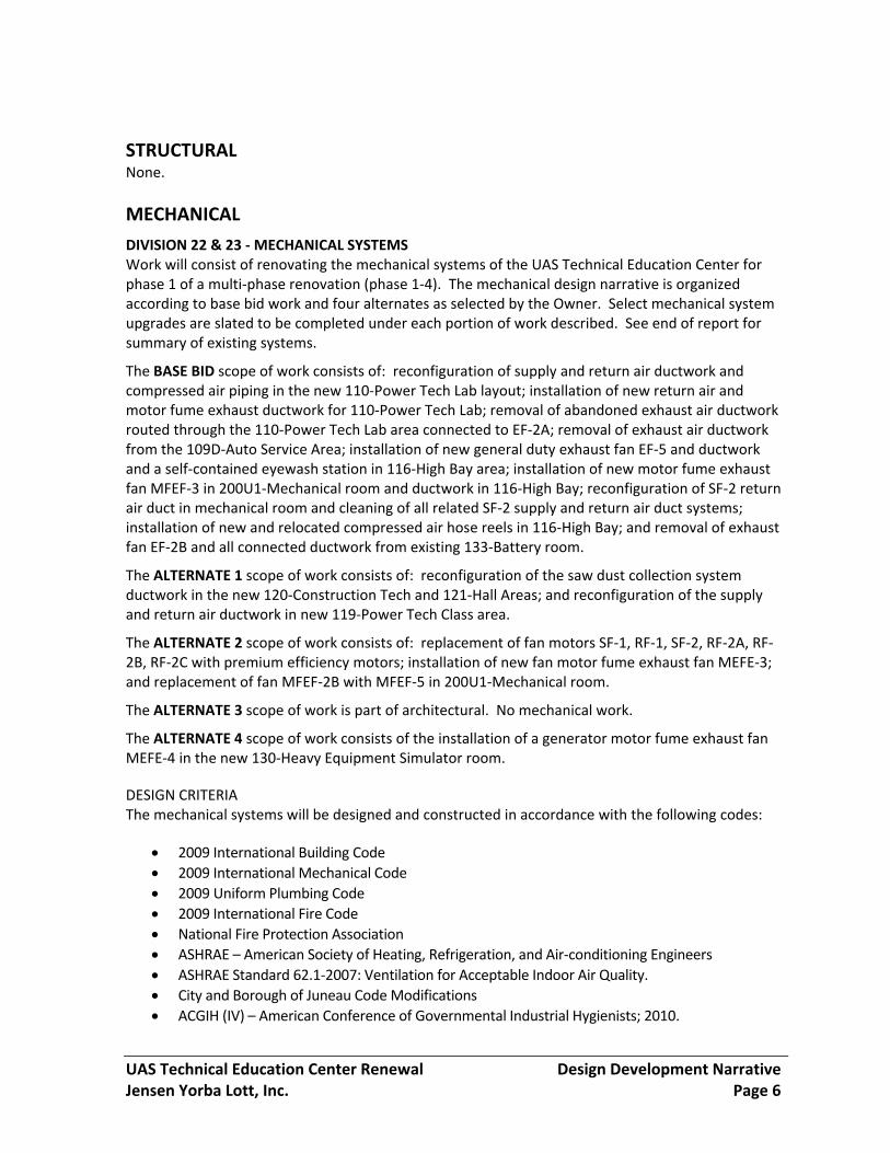
1EXISTING FIRST FLOOR PLAN - TECH CENTER
2EXISTING SECOND FLOOR PLAN
SCALE: 0 16'8' 32'
SCALE: 0 16'8' 32'
TECH CENTER
PHASE 1
ALT 2
ALT 4 - OPERABLE
ALT 5 - SLIDING FENCE
PHASING KEY
ALT 1
ALT 3
ALT 6 - COUNTER
PARTITION
No.
201
3-02
Tec
hn
ical
Ed
uca
tion
Cen
ter
Ren
ewal
YorbaJensen
Lott
Un
iver
sity
of
Ala
ska
Sou
thea
st
Jun
eau
, Ala
ska
Inc.
January, 2014
13078-PH 1
DATE:
FILE:
SHEET TITLE
REVISIONS
jensenyorbalott.comfax 907-586-3959
phone 907-586-1070Juneau, Alaska 99801
522 West 10th Street
.