scheme of thermogravimetric (tga)-temperature...
TRANSCRIPT

Flue-Gas and Direct-Air Capture of CO2 by Porous Metal-Organic Materials
Supporting Information
David G. Madden,† Hayley S. Scott,† Kai-Jie Chen,†Amrit Kumar,† Rana
Sanii,†AlankritiBajpai,† Matteo Lusi,† Teresa Curtin,*†‡ John J. Perry IV† and Michael J.
Zaworotko*†‡
† Department of Chemical and Environmental Sciences, University of Limerick, Limerick, Republic of Ireland‡ Materials & Surface Science Institute (MSSI), University of Limerick, Limerick, Republic of Ireland
* Contact Author, [email protected]
Table of Contents
Preparation of SIFSIX-3-Cu.....................................................................................................6
Preparation of SIFSIX-2-Cu-i...................................................................................................6
Preparation of DICRO-3-Ni-i....................................................................................................6
Preparation of MOOFOUR-1-Ni...............................................................................................7
Preparation of Ni-4-PyC...........................................................................................................7
Preparation of ZIF-8.................................................................................................................7
Preparation of DMOF-1............................................................................................................8
Preparation of MIL-101(Cr)......................................................................................................8
Preparation of UiO-66..............................................................................................................9
Preparation of UiO-66-NH2.......................................................................................................9
Powder X-ray Diffraction (PXRD).............................................................................................9
TGA-Temperature-Programmed Desorption (TPD) Studies..................................................10
Gas Sorption Measurements.................................................................................................11
Scheme of Thermogravimetric (TGA)-Temperature-Programmed Desorption (TPD)...........12
Powder X-ray Diffraction for SIFSIX-3-Cu..............................................................................13
Powder X-ray Diffraction for SIFSIX-2-Cu-i............................................................................13
Powder X-ray Diffraction for DICRO-3-Ni-i.............................................................................14
1

Powder X-ray Diffraction for MOOFOUR-1-Ni.......................................................................14
Powder X-ray Diffraction for Ni-4-PyC...................................................................................15
Powder X-ray Diffraction for ZIF-8.........................................................................................15
Powder X-ray Diffraction for DMOF-1....................................................................................16
Powder X-ray Diffraction for MIL-101.....................................................................................16
Powder X-ray Diffraction for UiO-66.......................................................................................17
Powder X-ray Diffraction for UiO-66-NH2...............................................................................17
Sorption isotherm for SIFSIX-3-Cu........................................................................................18
Sorption isotherms for SIFSIX-2-Cu-i.....................................................................................18
Sorption isotherms for DICRO-3-Ni-i......................................................................................19
Sorption isotherms for MOOFOUR-1-Ni................................................................................19
Sorption isotherms for Ni-4-PyC............................................................................................20
Sorption isotherms for ZIF-8..................................................................................................20
Sorption isotherms for DMOF-1.............................................................................................21
Sorption isotherms for MIL-101..............................................................................................21
Sorption isotherms for UiO-66................................................................................................22
Sorption isotherms for UiO-66-NH2........................................................................................22
TGA-TPD analysis for SIFSIX-3-Cu.......................................................................................23
TGA-TPD analysis for SIFSIX-2-Cu-i.....................................................................................26
TGA-TPD analysis for DICRO-3-Ni-i......................................................................................30
TGA-TPD analysis for MOOFOUR-1-Ni.................................................................................34
TGA-TPD analysis for Ni-4-PyC.............................................................................................38
TGA-TPD analysis for DMOF-1.............................................................................................42
TGA-TPD analysis for ZIF-8...................................................................................................46
TGA-TPD analysis for MIL-101..............................................................................................50
TGA-TPD analysis for UiO-66................................................................................................54
TGA-TPD analysis for UiO-66-NH2........................................................................................58
Accelerated Stability Testing for SIFSIX-3-Cu.......................................................................62
Lab temperature and relative humidity during DAC experiment............................................63
References.............................................................................................................................64
2
Solvents and reagents with the exception of 1,2-bis(4-pyridyl)acetylene (dpa) were
purchased from chemical suppliers and used without further purification. Methanol (ACS
Reagent Grade >99%), Ethanol (ACS Reagent Grade 96%), Acetonitrile (HPLC Grade,
>99.7%) and N,N′-Dimethylformamide ( HPLC Grade, >99.7%) were purchased from Sigma
Aldrich.
Preparation of {[Cu(pyr)2(SiF6)]n} (SIFSIX-3-Cu). The compound SIFSIX-3-Cu was
synthesized and activated using a modified synthesis from previous reports.[1] A hot
methanol solution (10 mL) of pyrazine (2 mmol) was slowly added into a hot methanol
solution (10 mL) of CuSiF6•H2O (1 mmol). The blue precipitate immoderately was obtained
and suspended in the solution. After stirring this mixture for 1 minute, SIFSIX-3-Cu was
harvested by direct filtration. Attention: longer stirring time will introduce more impurity. The
sample was then dried in the air and degassed under high vacuum at 50 °C for 12 hours
before use for sorption experiments.
Preparation of {[Cu(dpa)2(SiF6)]n} (SIFSIX-2-Cu-i). The compound SIFSIX-2-Cu-i was
synthesized and activated using a modified synthesis from previous reports. [1] dpa (150 mg,
0.833mmol) was dissolved in 20 mL of acetonitrile and added dropwise to a stirring aqueous
solution of Cu(NO3)2 (100 mg, 0.416mmol) and (NH4)2SiF6 (78 mg, 0.416mmol) and the
resulting solution was left stirring overnight. Following the reaction, SIFSIX-2-Cu-i was
obtained by filtration and washed with acetonitrile. Fine powder obtained after washing was
soaked in acetonitrile and the solvent was exchanged twice a day for three days before the
SIFSIX-2-Cu-i sample was used for sorption experiments. Activation of SIFSIX-2-Cu-i was
achieved by degassing the acetonitrile -exchanged sample on a SmartVacPrep™ using
dynamic vacuum for 36 hours.
Preparation of {[Ni(apy)2(Cr2O7)]}n (DICRO-3-Ni-i). The compound DICRO-3-Ni-i was synthesized and activated using a previous reported method.[2] K2Cr2O7 (294 mg, 1.0
mmol) and Ni(NO3)2·xH2O (1.0 mmol, 291 mg) were dissolved in 20 mL of water and stirred
at room temperature. Separately, 4,4′-azopyridine (368 mg, 2.0 mmol) was dissolved in 20
mL of acetonitrile. To the stirring aqueous solution of Ni(NO3)2 and K2Cr2O7, the 4,4’-
azopyridine solution in acetonitrile was added dropwise, to form an immediate precipitate.
The product was left stirring overnight, after which time it was removed from stirring and the
3

mother liquor exchanged with fresh acetonitrile twice a day until the solution became clear.
Fine powder obtained by filtration was activated by degassing the sample on a
SmartVacPrep™ using dynamic vacuum and heat (373K) for 12 hours.
Preparation of {[Ni(bpe)2(MoO4)]}n (MOOFOUR-1-Ni). The compound MOOFOUR-1-Ni was synthesized and activated using a previous reported method.[3] 3 mL of acetonitrile
and water (v/v = 1:2) was carefully layered over an aqueous solution (3 mL) of NiCl2.6H2O
(19.0 mg, 0.08 mmol) and Na2MoO4.2H2O (19.4 mg, 0.08 mmol) in a long thin test tube. 1,2-
bis(4-pyridyl)ethene (bpe) (18.2 mg, 0.1 mmol) in 3 mL of acetonitrile and water (v/v = 2:1)
was slowly layered over the buffer layer. The tube was sealed and left undisturbed at room
temperature. After 3 days light green block-shaped crystals were isolated from the buffer
layer. The obtained crystals was soaked in acetonitrile and the solvent was exchanged
twice a day for three days before the MOOFOUR-1-Ni sample was used for sorption
experiments. Activation of MOOFOUR-1-Ni was achieved by degassing the acetonitrile -
exchanged sample on a SmartVacPrep™ using dynamic vacuum and heat (333K) for 12
hours.
Preparation of {[Ni9(μ-H2O)4(H2O)2(C6NH4O2)18]}n (Ni-4-PyC). The compound Ni-4-PyC was synthesized and activated using a previous reported method.[4] NiCO3 (0.119 g; 1
mmol) and pyridine-4-carboxylic acid (0.244 g; 2 mmol) were added in a solution containing
1.5 ml of tetrahydrofuran (THF) + 2.5 ml of water + 2 ml of methanol and heated in a teflon-
lined steel bomb at 150 oC for 3 days. A bright blue–colored polycrystalline product was
isolated by filtration and was washed with plenty of water and methanol. The sample was
soaked in methanol and solvent exchange was carried out twice a day for three days before
the Ni-4-PyC sample was used for sorption experiments. Activation of Ni-4-PyC was
achieved by degassing the metahnol -exchanged sample on a SmartVacPrep™ using
dynamic vacuum and heat (373K) for 24 hours.
Preparation of {[Zn(MeIM)2]}n (ZIF-8). The compound ZIF-8 was synthesized and activated using a previous reported method.[5] A mixture of Zn(NO3)2.6H2O (0.210 g, .803
mmol) and 2-methylimidazole (H-MeIM) (0.060 g, .731 mmol) was dissolved in 18 ml of DMF
and heated in a teflon-lined steel bomb at 140 oC for 24 hours. After cooling and removal of
mother liquor from the mixture, chloroform (20 ml) was added to the vial. Colourless
4

polyhedral crystals were collected from the upper layer, washed with DMF (10 ml) and
soaked in methanol. The solvent was exchanged twice a day for three days before the ZIF-8 sample was used for sorption experiments. Activation of ZIF-8 was achieved by degassing
the methanol exchanged sample on a SmartVacPrep™ using dynamic vacuum and heat
(573K) for 6 hours.
Preparation of {[Zn2(bdc)2(dabco)]}n (DMOF-1). The compound DMOF-1 was synthesized and activated using a previous reported method.[6] A mixture of
Zn(NO3)2·6H2O (1.0 g, 3.36 mmol), H2bdc (0.560 g, 3.37 mmol), and dabco (0.187 g, 1.67
mmol) was suspended in DMF (40 mL) and heated in a teflon-lined steel bomb at 120 oC for
2 days. The colourless crystalline precipitate formed was collected, washed with DMF and
soaked in methanol. The solvent was exchanged twice a day for three days before the
DMOF-1 sample was used for sorption experiments. Activation of DMOF-1 was achieved by
degassing the metahnol -exchanged sample on a SmartVacPrep™ using dynamic vacuum
and heat (403K) for 24 hours.
Preparation of {[Cr3(O)F(bdc)3(H2O)2]n} (MIL-101(Cr)). The compound MIL-101 was
synthesized and activated using a synthesis method from previous report.[7] A solution
containing Cr(NO3)3·9H2O (400 mg, 1.0 mmol), HF acid (1.0 mmol) and benzene-1,4-
dicarboxylic acid H2bdc (164mg, 1.0mmol) in 5 mL H2O was transferred to the Teflon vessel
and heated for 8 h at 220°C. The solution was cooled gradually to room temperature at a
rate of 30 °C /h. Following the reaction, the contents of the autoclave was transferred to two
centrifuge tubes and the supernatant solution was carefully removed after centrifugation.
Water (5 mL) was added in each tube and the solid was evenly dispersed in the aqueous
phase. After renewed centrifugation and removal of the supernatant solution, DMF (5 mL)
was added to each tube which was placed in a hot (80 oC) ultrasonic bath and sonicated for
1 h. Centrifugation was again used to separate MIL-101 and DMF. The precipitate was
transferred in a 25 mL beaker where it was stirred with 10 mL of water at 70 oC for 5 h. After
separation by centrifugation, the same washing procedure but using ethanol was repeated
once more at the same temperature. Final product was obtained by centrifugation and
activation of MIL-101 was achieved by degassing the sample on a SmartVacPrep™ using
dynamic vacuum and heat (120 oC) for 12 hours.
5

Preparation of {[Zr6O4(OH)4(CO2)12]n} (UiO-66). The compound UiO-66 was synthesized
and activated using a synthesis method from previous report. [8] It was synthesized by
dissolving ZrCl4 (0.053 g, 0.227 mmol) and 1,4‐benzenedicarboxylic acid (H2BDC) (0.034g,
0.227 mmol) in N,N`‐dimethylformamide (DMF) (24.9 g, 340 mmol) at room temperature.
The thus obtained mixture was sealed in a Teflon vessel and placed in a pre‐heated oven at
120 ˚C for 24 hours. Crystallization was carried out under static conditions. After cooling in
air to room temperature the resulting solid was filtered, repeatedly washed with DMF and
dried at room temperature. The obtained UiO-66 was soaked in acetonitrile and the solvent
was exchanged twice a day for three days before the UiO-66 sample was used for sorption
experiments. Activation of UiO-66 was achieved by degassing the acetonitrile-exchanged
sample on a SmartVacPrep™ using dynamic vacuum and heat (150 °C) for 36 hours.
Preparation of UiO-66-NH2. The compound UiO-66-NH2 was synthesized and activated
using a synthesis method from previous report.[9] A standard upscaled synthesis of UiO-66-
NH2 was performed by dissolving ZrCl4 (1.50 g, 6.4 mmol) and 2-amino-1, 4-
benzenedicarboxylic acid (H2N-H2BDC) (1.56 g, 6.4 mmol) in DMF (180 mL) at room
temperature in a volumetric flask. The resulting mixture was placed in a preheated oven at
80 °C for 12 h and then held at 100 °C for 24 h. After the solution was cooled to room
temperature in air, the resulting solid was filtered and repeatedly washed with absolute
ethanol for 3 days while heated at 60 °C in a water bath. The resulting yellow powder was
filtered, transferred to a Schlenk flask, and dried under vacuum at ambient temperature.
Activation of UiO-66 was achieved by degassing the acetonitrile-exchanged sample on a
SmartVacPrep™ using dynamic vacuum and heat (150 °C) for 36 hours.
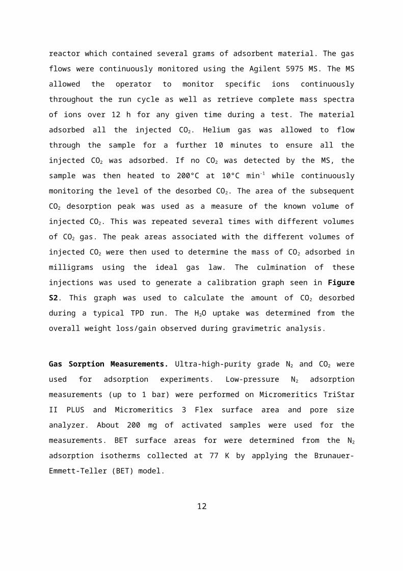
Powder X-ray Diffraction (PXRD).Powder X-ray diffraction experiments were carried out
using a PANalytical Empyrean™ diffractometer equipped with a PIXcel3D detector operating
in scanning line detector mode with an active length of 4 utilizing 255 channels. The
diffractometer is outfitted with an Empyrean Cu LFF (long fine-focus) HR (9430 033 7310x)
tube operated at 40 kV and 40 mA and Cu K-alpha radiation (λα = 1.540598 Å) was used for
diffraction experiments. Experiments were conducted in continuous scanning mode with the
goniometer in the theta-theta orientation. Incident beam optics included the Fixed
Divergences slit with anti-scatter slit PreFIX module, with a 1/8° divergence slit and a 1/4°
anti-scatter slit, as well as a 10 mm fixed incident beam mask and a Soller slit (0.04 rad).
Divergent beam optics included a P7.5 anti-scatter slit, a Soller slit (0.04 rad), and a Ni β
filter. The samples were typically dry and ground into a fine powder, applied to a low
6
background sample holder and mounted to a bracket flat sample stage. In a typical
experiment, data was collected via a continuous scan in the range of 5°- 45° (2θ) with a
step-size of 0.02626° and a scan time of 29 seconds per step. Raw data was then evaluated
using the X’PertHighScore Plus™ software V 4.1 (PANalytical, The Netherlands). Plots of
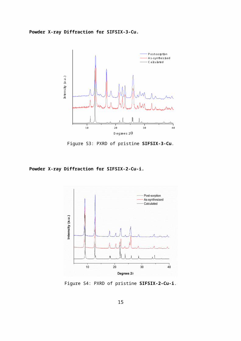
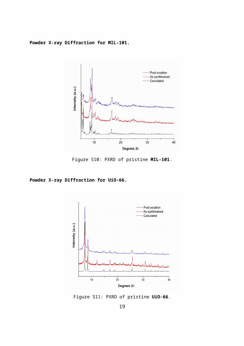
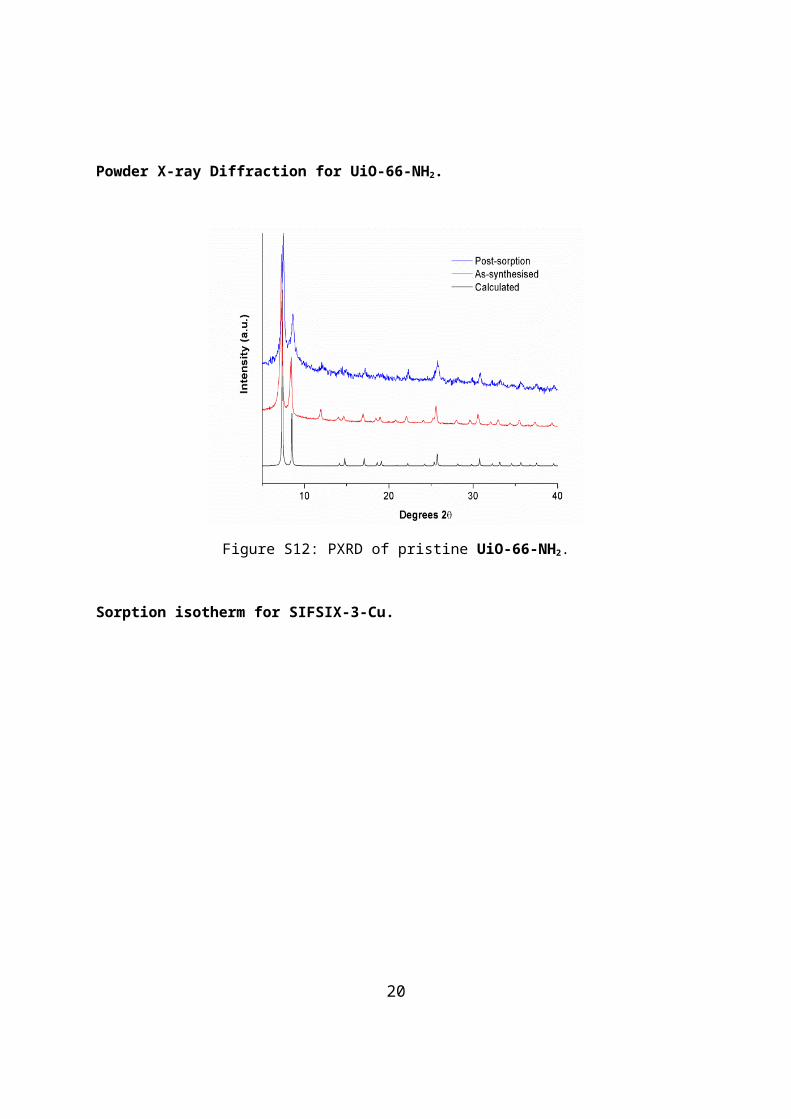
stacked PXRD spectra for each adsorbent displaying patterns for calculated, as synthesized,
solvent exchanged, and after sorption analysis are provided below (Fig. S3 – S12).
Additional plots of stacked PXRD spectra displaying patterns for calculated, pristine sample,
and post-humidity chamber exposure (after 1 day, 7 days, and 14 days) are provided for
each sorbent.
TGA-Temperature-Programmed Desorption (TPD) Studies.TGA-TPD studies were
carried out on a gas mixing rig coupled independently with a TGA instrument TA Q50 V20.13
Build 39 and mass spectrometer (MS) Agilent 5975 MSD, see Fig. S1 In a typical TGA
uptake test the given sample was activated by heating to a desired temperature under a 60
ml/min flow of nitrogen gas. This was then cooled to 30 °C before the chosen gas mixture
was introduced to the sample. A mass flow controller was used to control the gas ratios for
each test while moisture was introduced by passing the pre-mixed gas through a gas
bubbler containing water. The weight increase for each solid was monitored until the weight
began to plateau. The exposure time and gas flow conditions were then noted and
subsequently applied to samples during TPD studies to analyse the composition of the
adsorbed species during the desorption cycle.
TPD tests were carried out using a custom-made fixed-bed flow system. The system
consists of a gas delivery system, a reactor housed in a furnace and a mass spectrometer
detection system. There are two aims to this testing; to determine the CO2 adsorbed by the
sorbents; to examine the temperatures at which the CO2 desorption occurs. Both of these
parameters will be investigated using CO2 TPD profiles. In a typical CO2 TPD cycle, the
sorbent is placed in a quartz tubular reactor. The sample is fixed in the reactor using quartz
wool. Helium is then passed through the reactor at room temperature until a constant signal
is observed using an Agilent 5975 MSD mass spectrometer (MS). The temperature is then
increased at a rate of 10 °C·min-1 to an appropriate temperature to remove impurities in the
sample. The sample is then cooled to 30 °C. A gas mixture is then introduced to the sorbent
for the required length of time. When the required adsorption parameters have been
achieved, the gas flow is switched to nitrogen gas until the carbon dioxide concentrations are
returned to background levels. The carrier gas is then switched to helium and heated to the
7
required temperature at a rate of 10 °C·min-1 in a flow of helium. The gas composition
leaving the reactor is continuously monitored by MS for the identity and quantity of each
component of the desorbed gas. Helium is used as a carrier gas as this is not detected by
the MS, ensuring that all desorbed species from the adsorbents are detected.
During a direct air capture (DAC) test, a sample is activated under vacuum as per the
conditions previously outlined. This sample is then exposed to the laboratory environment for
24 h. The sample is then analyzed using TPD studies to analyze the composition of the
exhaust gas from the sorbent.
For calibration, a gas syringe (Valco precision sampling syringe, 2 ml, from Aldrich) was
used to introduce pure CO2, taken directly from a gas cylinder, into the system. Known
volumes of CO2 gas, between 0.2 ml and 5 ml, were injected at a location before the reactor
which contained several grams of adsorbent material. The gas flows were continuously
monitored using the Agilent 5975 MS. The MS allowed the operator to monitor specific ions
continuously throughout the run cycle as well as retrieve complete mass spectra of ions over
12 h for any given time during a test. The material adsorbed all the injected CO2. Helium gas
was allowed to flow through the sample for a further 10 minutes to ensure all the injected
CO2 was adsorbed. If no CO2 was detected by the MS, the sample was then heated to
200°C at 10°C min-1 while continuously monitoring the level of the desorbed CO2. The area
of the subsequent CO2 desorption peak was used as a measure of the known volume of
injected CO2. This was repeated several times with different volumes of CO2 gas. The peak
areas associated with the different volumes of injected CO2 were then used to determine the
mass of CO2 adsorbed in milligrams using the ideal gas law. The culmination of these
injections was used to generate a calibration graph seen in Figure S2. This graph was used
to calculate the amount of CO2 desorbed during a typical TPD run. The H2O uptake was
determined from the overall weight loss/gain observed during gravimetric analysis.
Gas Sorption Measurements. Ultra-high-purity grade N2 and CO2 were used for adsorption
experiments. Low-pressure N2 adsorption measurements (up to 1 bar) were performed on
Micromeritics TriStar II PLUS and Micromeritics 3 Flex surface area and pore size analyzer.
About 200 mg of activated samples were used for the measurements. BET surface areas for
were determined from the N2 adsorption isotherms collected at 77 K by applying the
Brunauer-Emmett-Teller (BET) model.
8
Scheme of Thermogravimetric (TGA)-Temperature-Programmed Desorption (TPD).
Figure S1: Schematic of gas mixing system, TGA uptake analysis and TPD analysis units.
Figure S2: CO2 calibration graph.
9

Powder X-ray Diffraction for SIFSIX-3-Cu.
10 20 30 40
Inte
nsity
(a.u
.)
Degrees 2
Post-sorption As-synthesised Calculated
Figure S3: PXRD of pristine SIFSIX-3-Cu.
Powder X-ray Diffraction for SIFSIX-2-Cu-i.
Figure S4: PXRD of pristine SIFSIX-2-Cu-i.
10

Powder X-ray Diffraction for DICRO-3-Ni-i.
Figure S5: PXRD of pristine DICRO-3-Ni-i.
Powder X-ray Diffraction for MOOFOUR-1-Ni.
Figure S6: PXRD of pristine MOOFOUR-1-Ni..
11
Powder X-ray Diffraction for Ni-4-PyC.
Figure S7: PXRD of pristine Ni-4-PyC.
Powder X-ray Diffraction for ZIF-8.
Figure S8: PXRD of pristine ZIF-8.
12

Powder X-ray Diffraction for DMOF-1.
Figure S9: PXRD of pristine DMOF-1.
Powder X-ray Diffraction for MIL-101.
Figure S10: PXRD of pristine MIL-101.
13

Powder X-ray Diffraction for UiO-66.
Figure S11: PXRD of pristine UiO-66.
Powder X-ray Diffraction for UiO-66-NH2.
Figure S12: PXRD of pristine UiO-66-NH2.
14
Sorption isotherm for SIFSIX-3-Cu.
0 100 200 300 400 500 600 700 8000
100
(cm
3 /g S
TP)
(mmHg)
293K CO2 Ads 293K CO2 Des
Figure S13: CO2 sorption isotherm on pristine SIFSIX-3-Cu.
Sorption isotherms for SIFSIX-2-Cu-i.
Figure S14: CO2 and N2 sorption isotherms on pristine SIFSIX-2-Cu-i.
15

Sorption isotherms for DICRO-3-Ni-i.
0 100 200 300 400 500 600 700 8000
100
(cm
3 /g S
TP)
(mmHg)
77K N2 Ads 77K N2 Des 293K CO2 Ads 293K CO2 Des
Figure S15: CO2 and N2 sorption isotherms on pristine DICRO-3-Ni-i.
Sorption isotherms for MOOFOUR-1-Ni.
Figure S16: CO2 sorption isotherms on pristine MOOFOUR-1-Ni.
16

Sorption isotherms for Ni-4-PyC.
Figure S17: CO2 and N2 sorption isotherms on pristine Ni-4-PyC.
Sorption isotherms for ZIF-8.
Figure S18: CO2 and N2 sorption isotherms on pristine ZIF-8.
17

Sorption isotherms for DMOF-1.
Figure S19: CO2 and N2 sorption isotherms on pristine DMOF-1.
Sorption isotherms for MIL-101.
Figure S20: CO2 and N2 sorption isotherms on pristine MIL-101.
18
Sorption isotherms for UiO-66.
Figure S21: CO2 and N2 sorption isotherms on pristine UiO-66.
Sorption isotherms for UiO-66-NH2.
Figure S22: CO2 and N2 sorption isotherms on pristine UiO-66-NH2.
19
TGA-TPD analysis for SIFSIX-3-Cu.
Figure S23: TPD profiles and composition for SIFSIX-3-Cu DAC test.
Figure S24: Dry 1.0 atm CO2 uptake test using TGA for SIFSIX-3-Cu.
20

Figure S25: Moist 0.15 atm CO2 uptake test using TGA for SIFSIX-3-Cu.
Figure S26: TPD profiles and composition for SIFSIX-3-Cu moist 0.15 atm CO2 test.
21

Figure S27: Dry 0.15 atm CO2 uptake test using TGA for XXXX.
22

TGA-TPD analysis for SIFSIX-2-Cu-i.
Figure S28: TPD profiles and composition for SIFSIX-2-Cu-i DAC test.
Figure S29: Moist N2 uptake test using TGA for SIFSIX-2-Cu-i.
23
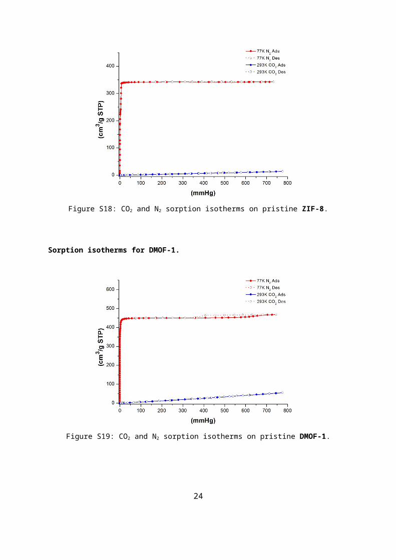
Figure S30: Moist 1.0 atm CO2 uptake test using TGA for SIFSIX-2-Cu-i.
Figure S31: TPD profiles and composition for SIFSIX-2-Cu-i moist 1.0 atm CO2 test.
24

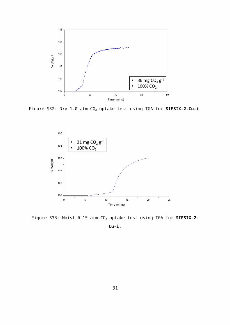
Figure S32: Dry 1.0 atm CO2 uptake test using TGA for SIFSIX-2-Cu-i.
Figure S33: Moist 0.15 atm CO2 uptake test using TGA for SIFSIX-2-Cu-i.
25

Figure S34: TPD profiles and composition for SIFSIX-2-Cu-i moist 0.15 atm CO2 test.
Figure S35: Dry 0.15 atm CO2 uptake test using TGA for SIFSIX-2-Cu-i.
26

TGA-TPD analysis for DICRO-3-Ni-i.
Figure S36: TPD profiles and composition for DICRO-3-Ni-i DAC test.
Figure S37: Moist N2 uptake test using TGA for DICRO-3-Ni-i.
27
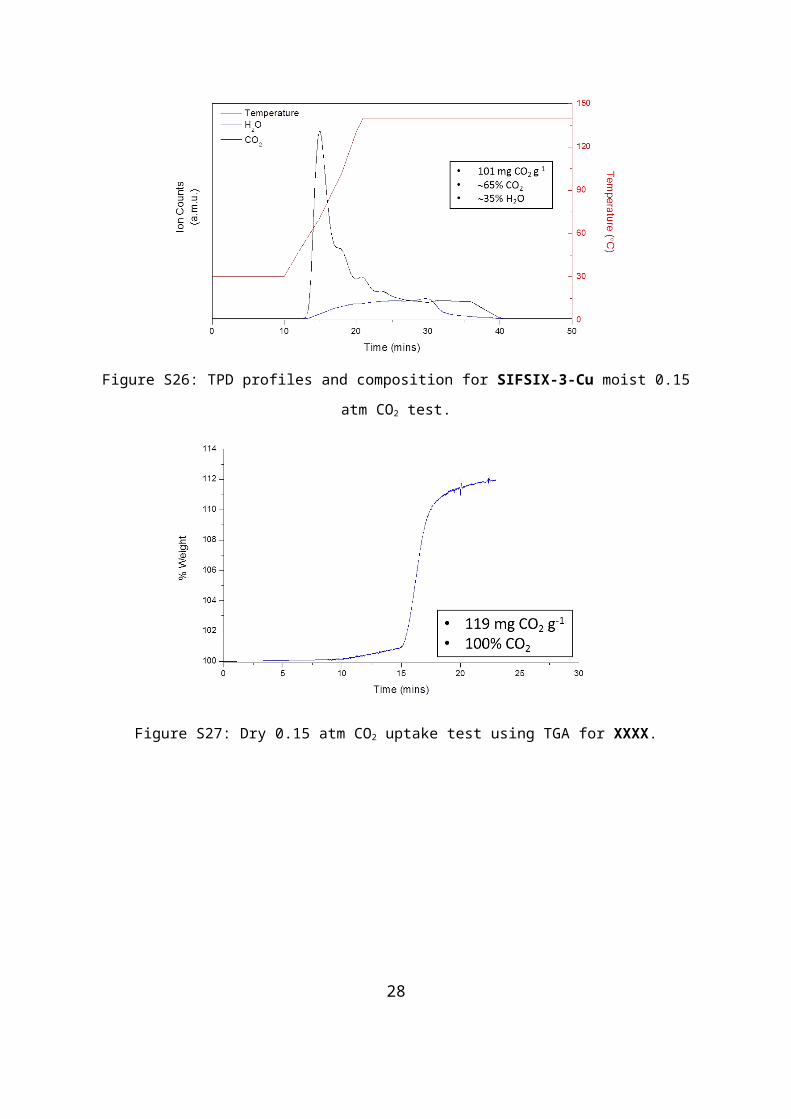
Figure S38: Moist 1.0 atm CO2 uptake test using TGA for DICRO-3-Ni-i.
Figure S39: TPD profiles and composition for DICRO-3-Ni-i moist 1.0 atm CO2 test.
28
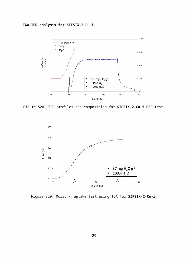
Figure S40: Dry 1.0 atm CO2 uptake test using TGA for DICRO-3-Ni-i.
Figure S41: Moist 0.15 atm CO2 uptake test using TGA for DICRO-3-Ni-i.
29

Figure S42: TPD profiles and composition for DICRO-3-Ni-i moist 0.15 atm CO2 test.
Figure S43: Dry 0.15 atm CO2 uptake test using TGA for DICRO-3-Ni-i.
30
TGA-TPD analysis for MOOFOUR-1-Ni.
Figure S44: TPD profiles and composition for MOOFOUR-1-Ni DAC test.
Figure S45: Moist N2 uptake test using TGA for MOOFOUR-1-Ni.
31

Figure S46: Moist 1.0 atm CO2 uptake test using TGA for MOOFOUR-1-Ni.
Figure S47: TPD profiles and composition for MOOFOUR-1-Ni moist 1.0 atm CO2 test.
32
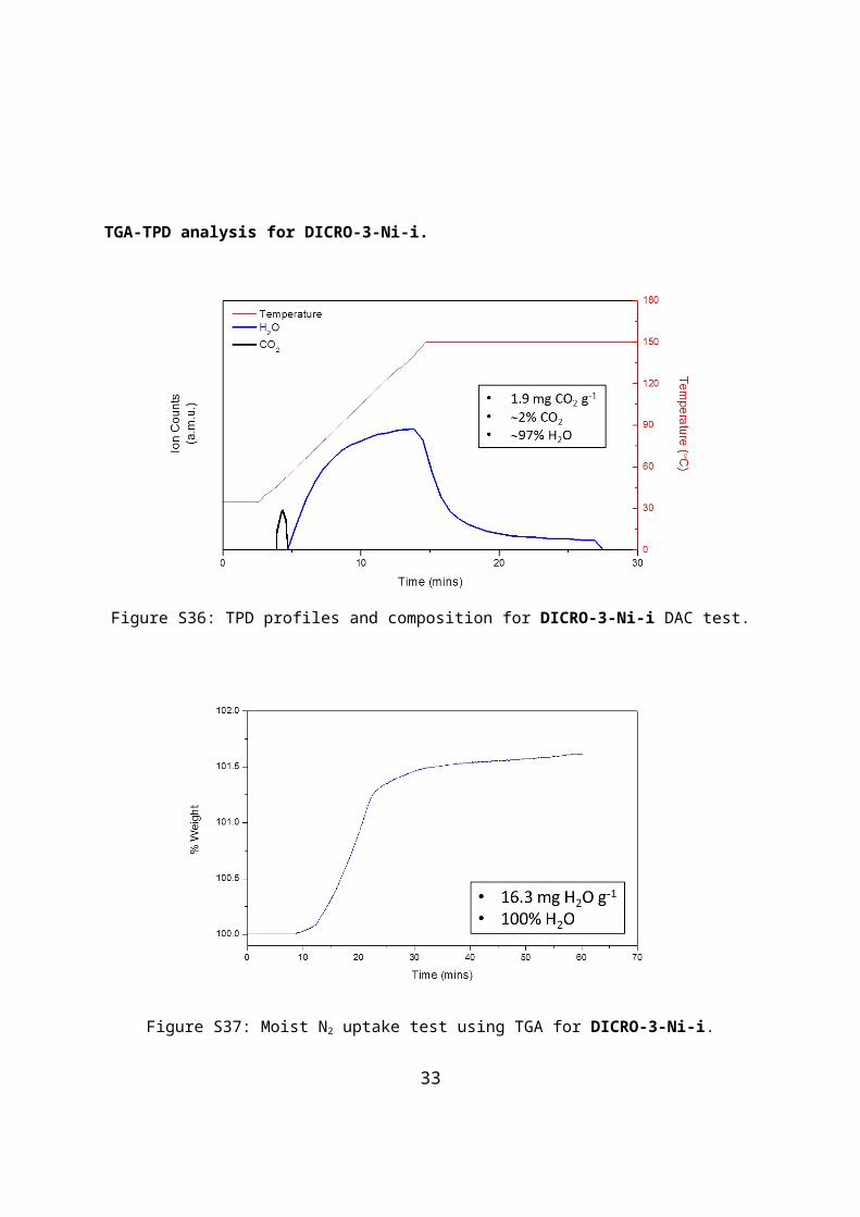
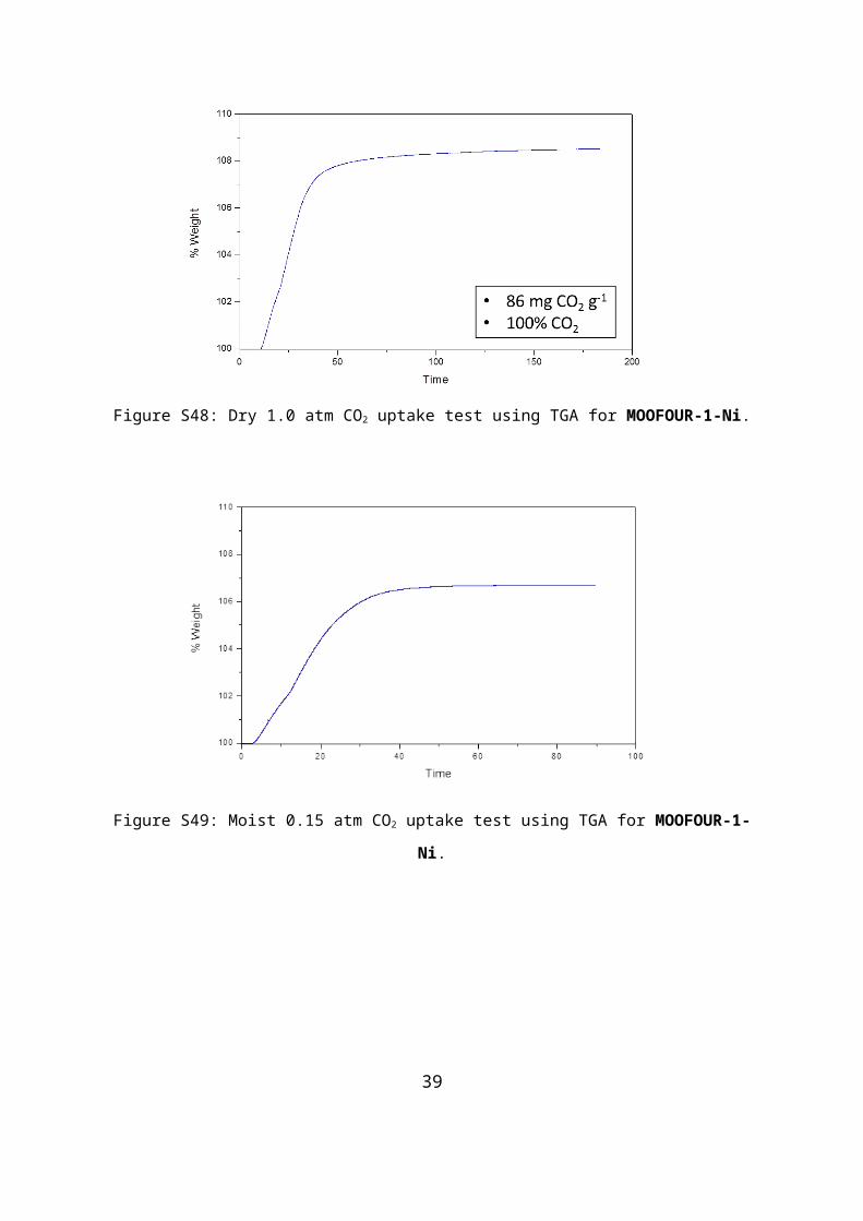
Figure S48: Dry 1.0 atm CO2 uptake test using TGA for MOOFOUR-1-Ni.
Figure S49: Moist 0.15 atm CO2 uptake test using TGA for MOOFOUR-1-Ni.
33
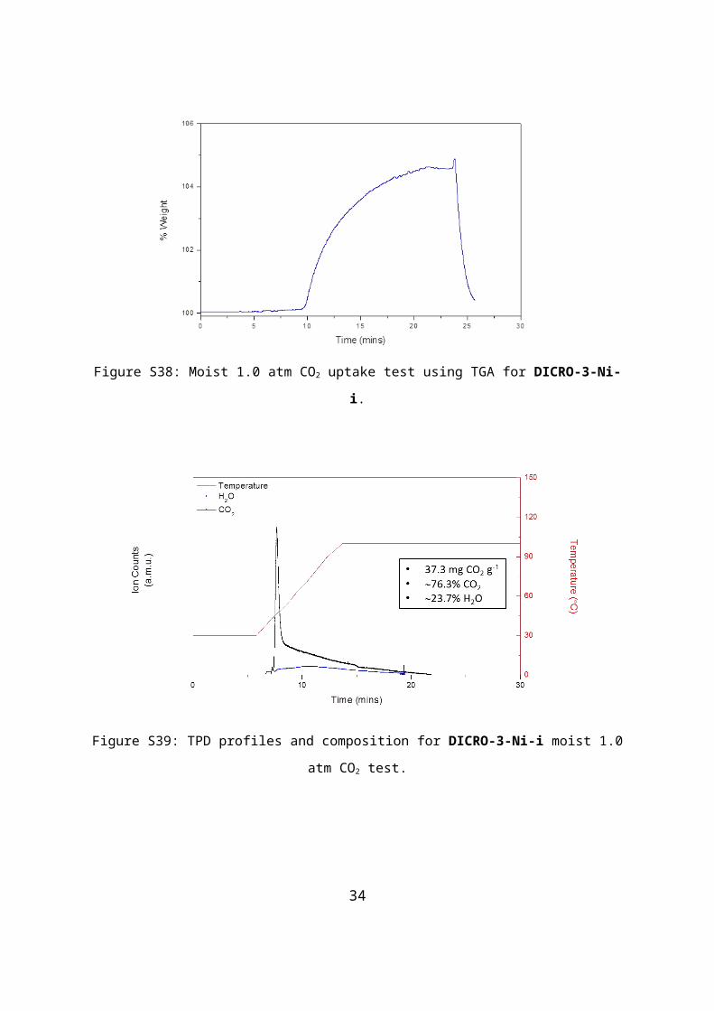
Figure S50: TPD profiles and composition for MOOFOUR-1-Ni moist 0.15 atm CO2 test.
Figure S51: Dry 0.15 atm CO2 uptake test using TGA for MOOFOUR-1-Ni.
34

TGA-TPD analysis for Ni-4-PyC.
Figure S52: TPD profiles and composition for Ni-4-PyC DAC test.
Figure S53: Moist N2 uptake test using TGA for Ni-4-PyC.
35
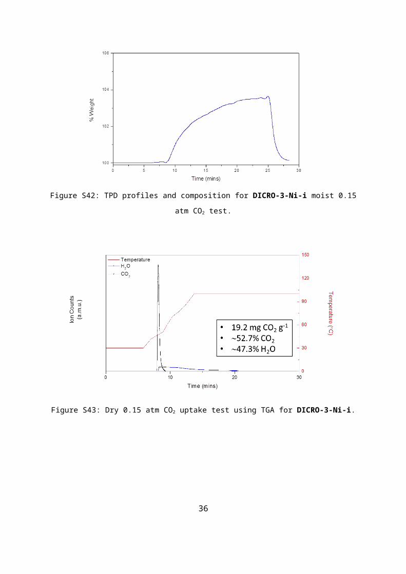
Figure S54: Moist 1.0 atm CO2 uptake test using TGA for Ni-4-PyC.
Figure S55: TPD profiles and composition for Ni-4-PyC moist 1.0 atm CO2 test.
36

Figure S56: Dry 1.0 atm CO2 uptake test using TGA for Ni-4-PyC.
Figure S57: Moist 0.15 atm CO2 uptake test using TGA for Ni-4-PyC.
37

Figure S58: TPD profiles and composition for Ni-4-PyC moist 0.15 atm CO2 test.
Figure S59: Dry 0.15 atm CO2 uptake test using TGA for Ni-4-PyC.
38
TGA-TPD analysis for DMOF-1.
Figure S60: TPD profiles and composition for DMOF-1 DAC test.
Figure S61: Moist N2 uptake test using TGA for DMOF-1.
39
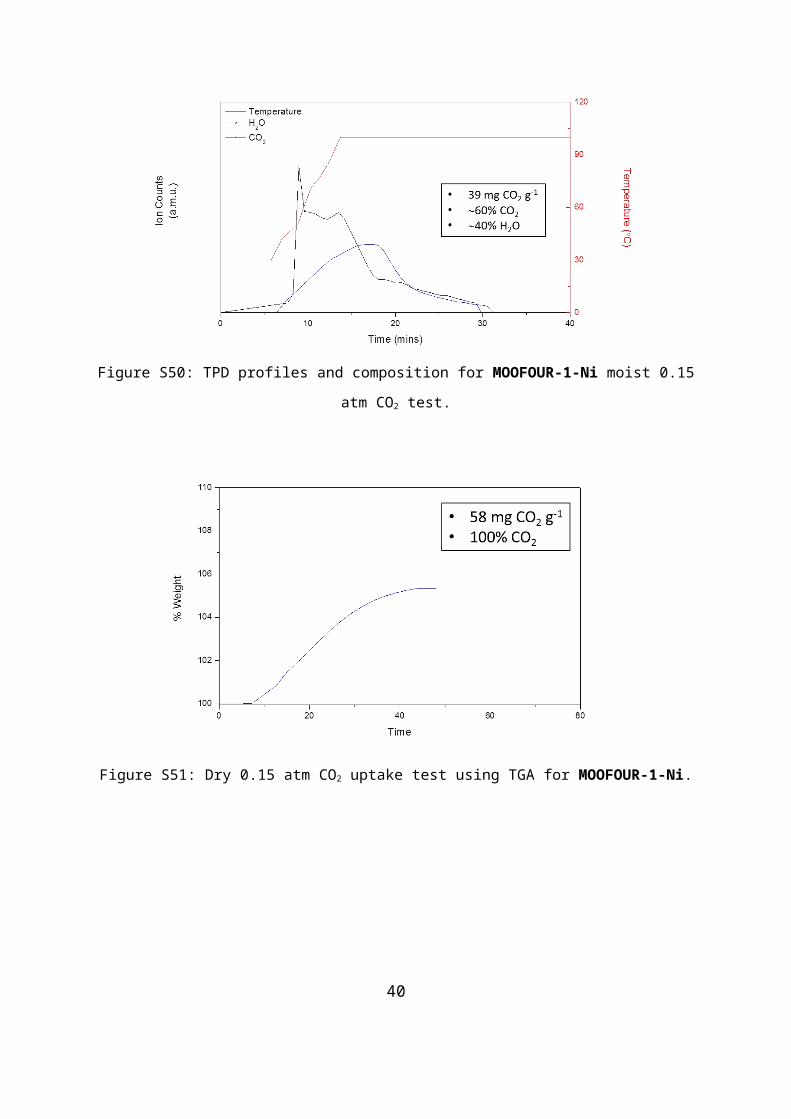
Figure S62: Moist 1.0 atm CO2 uptake test using TGA for DMOF-1.
Figure S63: TPD profiles and composition for DMOF-1 moist 1.0 atm CO2 test.
40
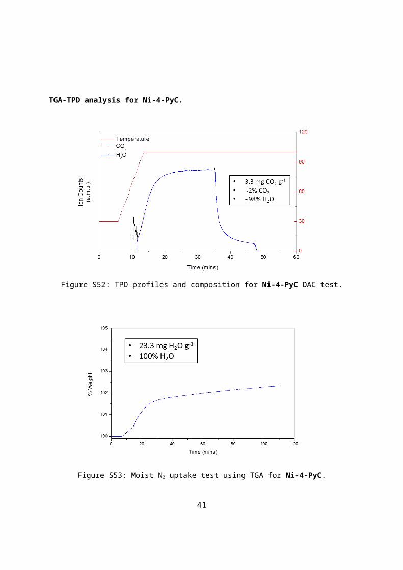
Figure S64: Dry 1.0 atm CO2 uptake test using TGA for DMOF-1.
Figure S65: Moist 0.15 atm CO2 uptake test using TGA for DMOF-1.
41
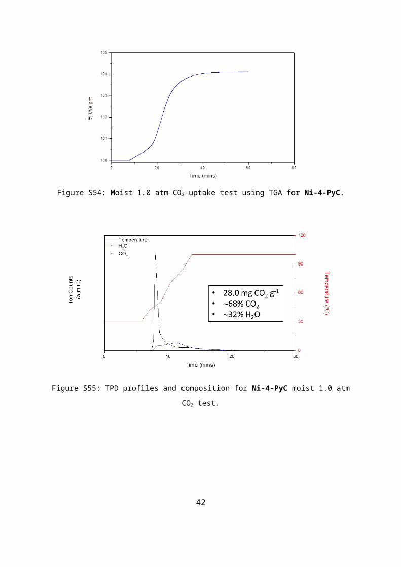
Figure S66: TPD profiles and composition for DMOF-1 moist 0.15 atm CO2 test.
Figure S67: Dry 0.15 atm CO2 uptake test using TGA for DMOF-1.
42

TGA-TPD analysis for ZIF-8.
Figure S68: TPD profiles and composition for ZIF-8 DAC test.
Figure S69: Moist N2 uptake test using TGA for ZIF-8.
43
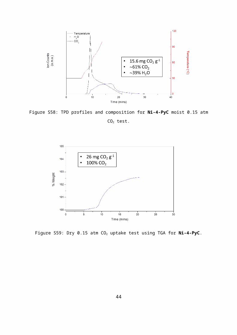
Figure S70: Moist 1.0 atm CO2 uptake test using TGA for ZIF-8.
Figure S71: TPD profiles and composition for ZIF-8 moist 1.0 atm CO2 test.
44

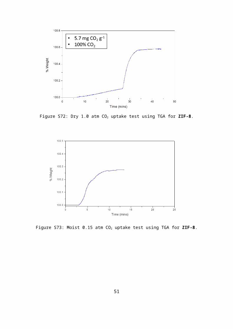
Figure S72: Dry 1.0 atm CO2 uptake test using TGA for ZIF-8.
Figure S73: Moist 0.15 atm CO2 uptake test using TGA for ZIF-8.
45

Figure S74: TPD profiles and composition for ZIF-8 moist 0.15 atm CO2 test.
Figure S75: Dry 0.15 atm CO2 uptake test using TGA for ZIF-8.
46

TGA-TPD analysis for MIL-101.
Figure S76: TPD profiles and composition for MIL-101 DAC test.
Figure S77: Moist N2 uptake test using TGA for MIL-101.
47
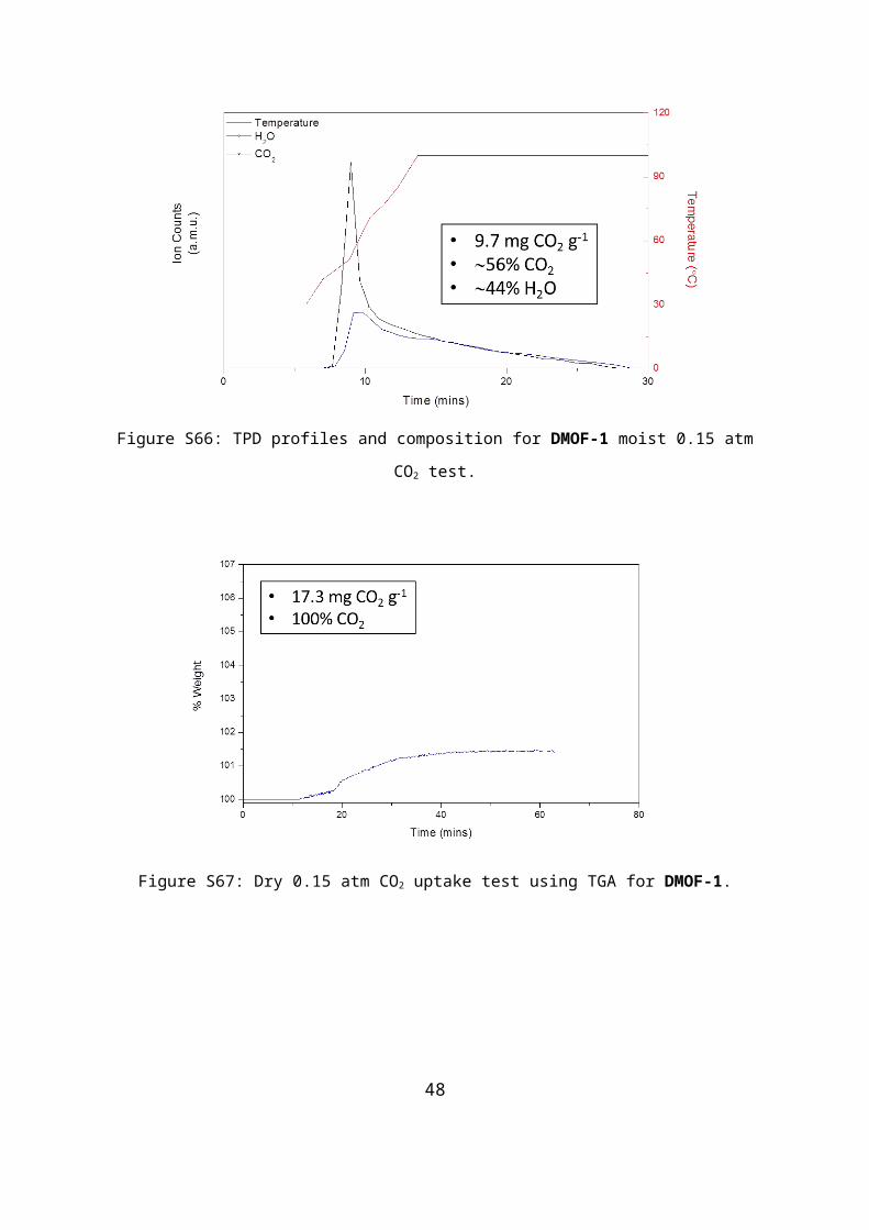
Figure S78: Moist 1.0 atm CO2 uptake test using TGA for MIL-101.
Figure S79: TPD profiles and composition for MIL-101 moist 1.0 atm CO2 test.
48
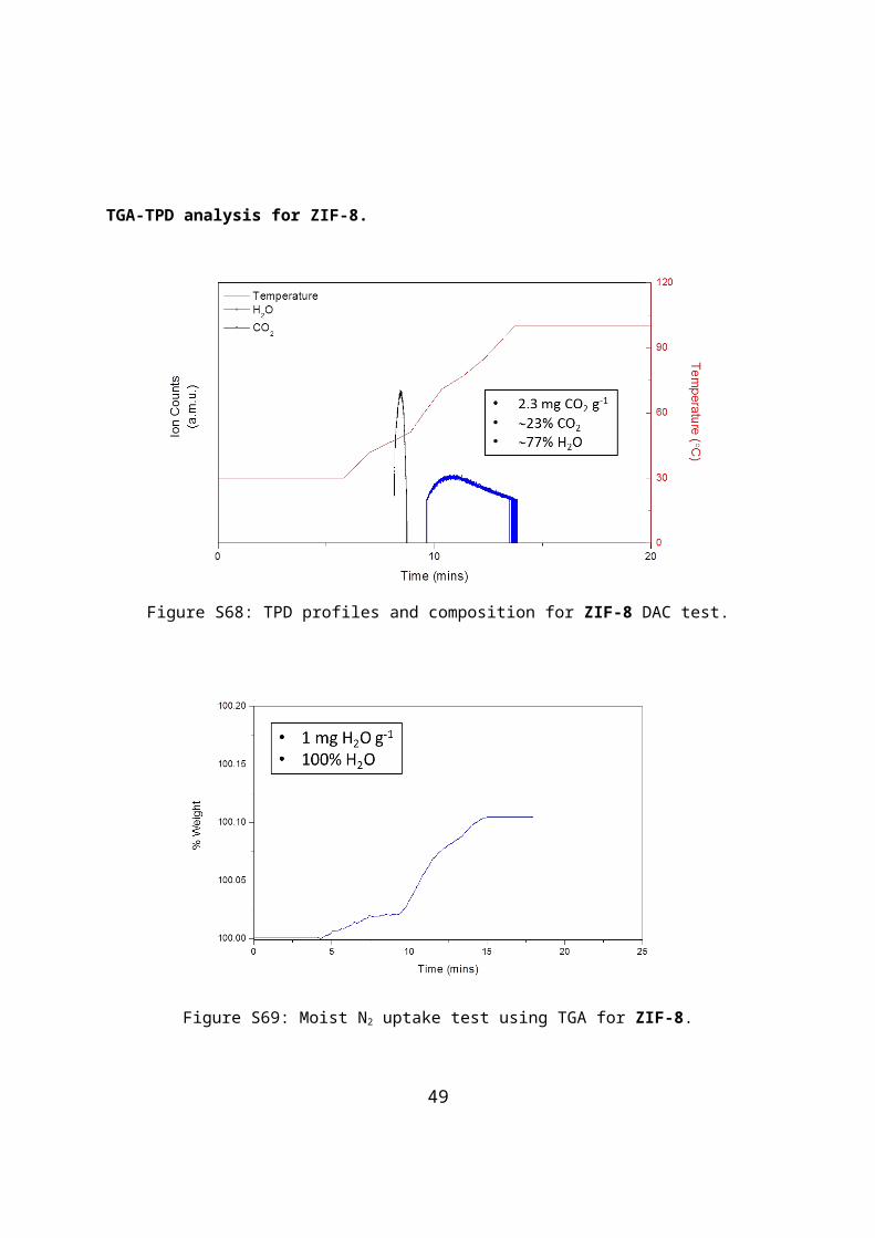
Figure S80: Dry 1.0 atm CO2 uptake test using TGA for MIL-101.
Figure S81: Moist 0.15 atm CO2 uptake test using TGA for MIL-101.
49
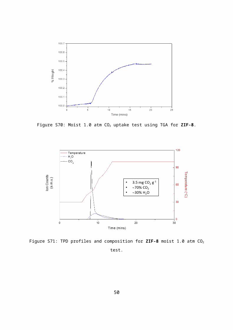
Figure S82: TPD profiles and composition for MIL-101 moist 0.15 atm CO2 test.
Figure S83: Dry 0.15 atm CO2 uptake test using TGA for MIL-101.
50
TGA-TPD analysis for UiO-66.
Figure S84: TPD profiles and composition for UiO-66 DAC test.
Figure S85: Moist N2 uptake test using TGA for UiO-66.
51
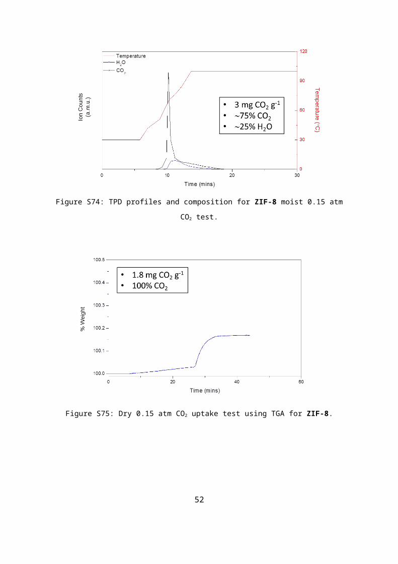
Figure S86: Moist 1.0 atm CO2 uptake test using TGA for UiO-66.
Figure S87: TPD profiles and composition for UiO-66 moist 1.0 atm CO2 test.
52

Figure S88: Dry 1.0 atm CO2 uptake test using TGA for UiO-66.
Figure S89: Moist 0.15 atm CO2 uptake test using TGA for UiO-66.
53

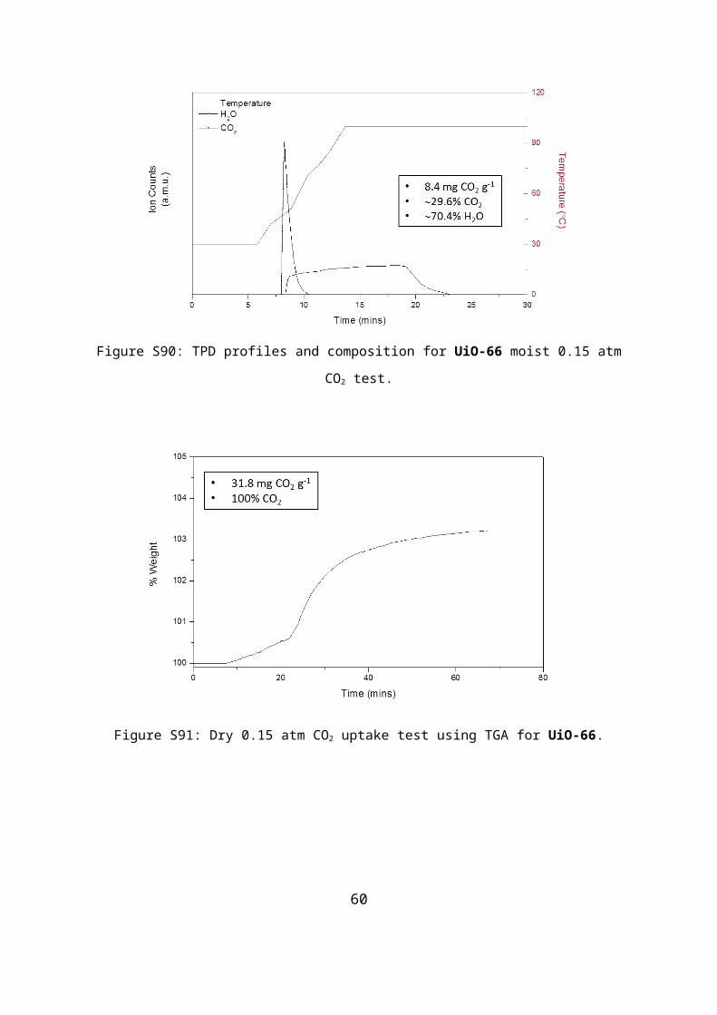
Figure S90: TPD profiles and composition for UiO-66 moist 0.15 atm CO2 test.
Figure S91: Dry 0.15 atm CO2 uptake test using TGA for UiO-66.
54

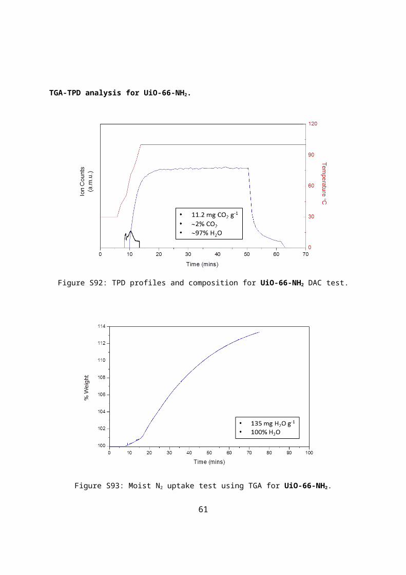
TGA-TPD analysis for UiO-66-NH2.
Figure S92: TPD profiles and composition for UiO-66-NH2 DAC test.
Figure S93: Moist N2 uptake test using TGA for UiO-66-NH2.
55

Figure S94: Moist 1.0 atm CO2 uptake test using TGA for UiO-66-NH2.
Figure S95: TPD profiles and composition for UiO-66-NH2 moist 1.0 atm CO2 test.
56
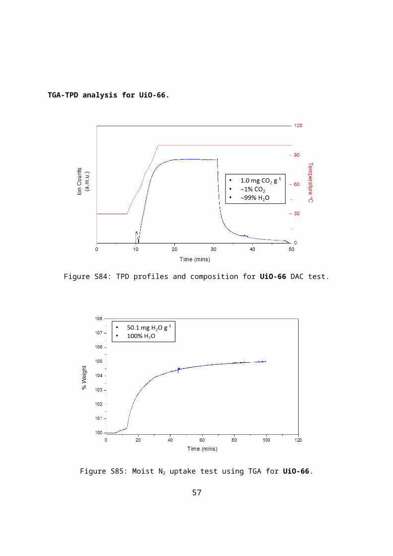
Figure S96: Dry 1.0 atm CO2 uptake test using TGA for UiO-66-NH2.
Figure S97: Moist 0.15 atm CO2 uptake test using TGA for UiO-66-NH2.
57

Figure S98: TPD profiles and composition for UiO-66-NH2 moist 0.15 atm CO2 test.
Figure S99: Dry 0.15 atm CO2 uptake test using TGA for UiO-66-NH2.
58

Accelerated Stability Testing for SIFSIX-3-Cu
Figure S100: Powder X-ray diffraction patterns for SIFSIX-3-Cu after 1 day accelerated stability testing (40 °C, 75% RH) compared with a post-TPD study sample.
Figure S101: % of pristine materials surface area retained after accelerated stability (40 °C, 75% RH) for SIFSIX-3-Cu compared with SIFSIX-3-Ni and Zeolite 13X.
59
Lab temperature and relative humidity during DAC experiment.
Figure S102: Lab temperature and relative humidity during DAC experiment.
60
References
[1] P. Nugent, Y. Belmabkhout, S. D. Burd, A. J. Cairns, R. Luebke, K. Forrest, T. Pham, S. Ma, B. Space, L. Wojtas, M. Eddaoudi, M. J. Zaworotko, Nature, 2013, 495, 80-84.
[2] Scott, H. S.; Ogiwara, N.; Chen, K.-J.; Madden, D. G.; Pham, T.; Space, B.; Hiroke, S.; IV, J. J. P.; Kitagawa, S.; Zaworotko, M. J., Chemical Science, 2016. (Just Accepted)
[3] M. H. Mohamed, S. K. Elsaidi, L. Wojtas, T. Pham, K. A. Forrest, B. Tudor, B. Space, M. J. Zaworotko, Journal of the American Chemical Society, 2012, 134, 19556-19559.
[4] S. Nandi, P. De Luna, T. D. Daff, J. Rother, M. Liu, W. Buchanan, A. I. Hawari, T. K. Woo, R. Vaidhyanathan, Science Advances, 2015, 1.
[5] K. S. Park, Z. Ni, xf, xe, A. P., J. Y. Choi, R. Huang, F. J. Uribe-Romo, H. K. Chae, M. O'Keeffe, O. M. Yaghi, Proceedings of the National Academy of Sciences of the United States of America, 2006, 103, 10186-10191.
[6] D. N. Dybtsev, H. Chun, K. Kim, Angewandte Chemie International Edition, 2004, 43, 5033-5036.
[7] T. Zhao, F. Jeremias, I. Boldog, B. Nguyen, S. K. Henninger, C. Janiak, Dalton Transactions, 2015, 44, 16791-16801.
[8] J. H. Cavka, S. Jakobsen, U. Olsbye, N. Guillou, C. Lamberti, S. Bordiga, K. P. Lillerud, Journal of the American Chemical Society, 2008, 130, 13850-13851.
[9] M. Kandiah, M. H. Nilsen, S. Usseglio, S. Jakobsen, U. Olsbye, M. Tilset, C. Larabi, E. A. Quadrelli, F. Bonino, K. P. Lillerud, Chemistry of Materials, 2010, 22, 6632-6640.
61