schlumberger basic mwd
DESCRIPTION
Schlumberger Basic MWDTRANSCRIPT
Sch
lum
berg
er Private
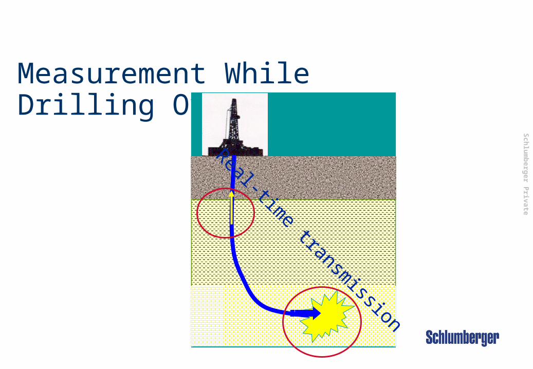
Measurement While Drilling Overview
Real-time transm
ission
Sch
lum
berg
er Private
2 Initials
MWD Functions Real-time surveying
Wellbore positioning
Directional Drilling
Real-time formation measurement
transmission
Correlation
Geology
Petrophysics
Geosteering
Real-time drilling mechanics data
Help Drilling process
Sch
lum
berg
er Private
3 Initials
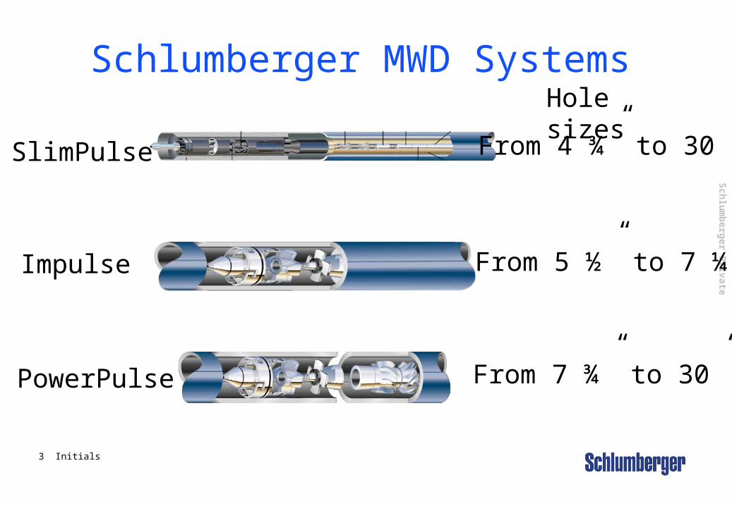
Schlumberger MWD SystemsHole sizes
SlimPulse From 4 ¾” to 30”
Impulse From 5 ½” to 7 ¼”
PowerPulse From 7 ¾” to 30”
Sch
lum
berg
er Private
4 Initials
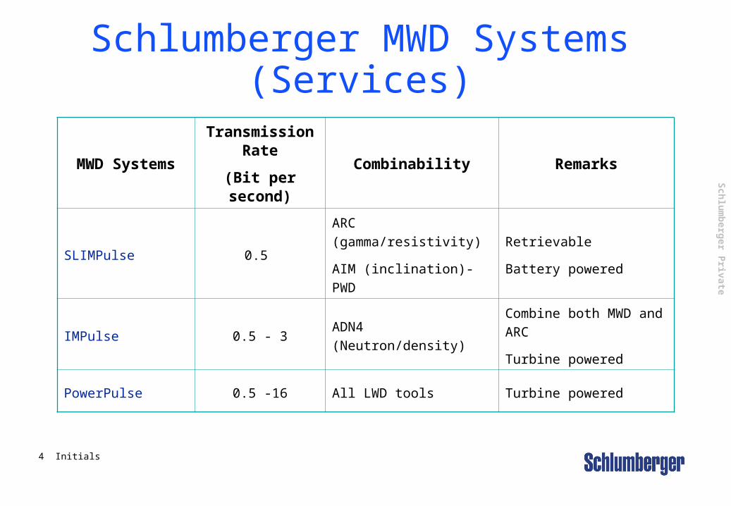
Schlumberger MWD Systems (Services)
MWD Systems
Transmission Rate
(Bit per second)
Combinability Remarks
SLIMPulse 0.5
ARC (gamma/resistivity)
AIM (inclination)-PWD
Retrievable
Battery powered
IMPulse 0.5 - 3 ADN4 (Neutron/density)
Combine both MWD and ARC
Turbine powered
PowerPulse 0.5 -16 All LWD tools Turbine powered

Sch
lum
berg
er Private
5 Initials
MWD Surveying – Is it important? (1)
While Drilling......... We want to1- Control the position of wellbore versus Geological model2- React when unexpected events are encountered3- Anticipate unexpected structural events
Sch
lum
berg
er Private
6 Initials
MiscellaneousSlot: Slot A-4 H Plan# : A4H rev9 160101Elev Ref: Platform Elevation(25.00m above MSL)Date Drawn: 06:16:00PM 30-Jan-2001
Surface LocationLat: N58 42 44.251 Lon: E1 40 5.641North: 6508932.00 m East: 422849.00 mGrid Conv: -1.1381° Scale Fact:0.9997
Magnetic ParametersModel: BGGM 2000Dip: 71.719° Mag Dec: -3.592°Date: December 22, 2000 FS: 50166.9 nT
GlitneSTRUCTURE
15/5 and 15/6 AreaFIELD
Well 13/5-6 - A-4 HWELL
-1200 -1000 -800 -600 -400 -200 0 200 400 600 800
-600
-400
-200
0
200
400
-1200 -1000 -800 -600 -400 -200 0 200 400 600 800
-600
-400
-200
0
200
400
Default Color Main Proposal Survey
1600
1500
1400
1300
1200
A-3 H Plan
2325
2300
2200
2100
2000
1900
1800
1700
1600
1500
1400
1300
A-2 H Pilot Survey
21772177
2100
2000
1900
A-2 AH Survey
2100
200
0
19
00
18
00
17
00
16
00
A-1 H Survey
2100
2000
1900
1800
17
00
16
00
15
00
14
00
13
00
12
00
A4H Plan
SPIDER VIEW
Scale (1 cm = 100 m)
<<< SOUTH NORTH >>>
<<< WEST EAST >>>
6354
6355
6356
6357
6358
6359
6360
6361
6362500 600 700 800 900
TV
D (
ft)
Vertical Section (ft)
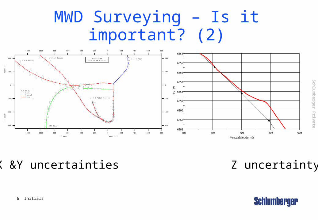
MWD Surveying – Is it important? (2)
X &Y uncertainties Z uncertainty
Sch
lum
berg
er Private
7 Initials
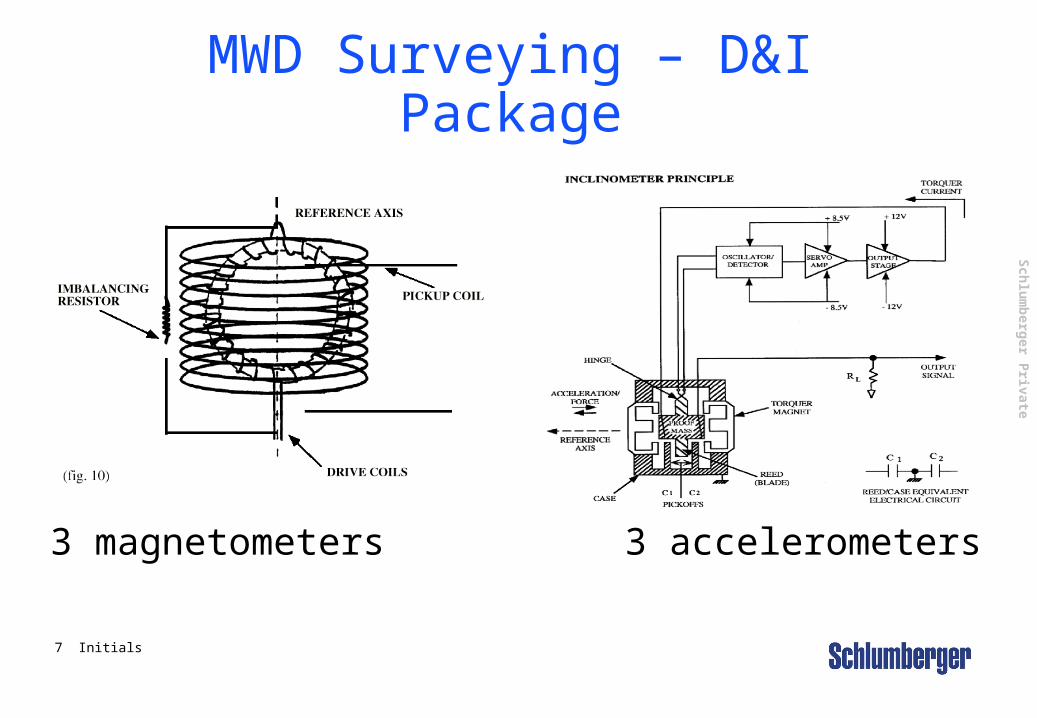
3 magnetometers 3 accelerometers
MWD Surveying – D&I Package

Sch
lum
berg
er Private
8 Initials
MWD Surveying – Affected by?
Magnetic data affected by any magnetic interferences•Bottom Hole assembly•Nearby casing•Magnetic storms
Inclinometer data affected by:•Accuracy limit•Surveying procedures
Sch
lum
berg
er Private
9 Initials
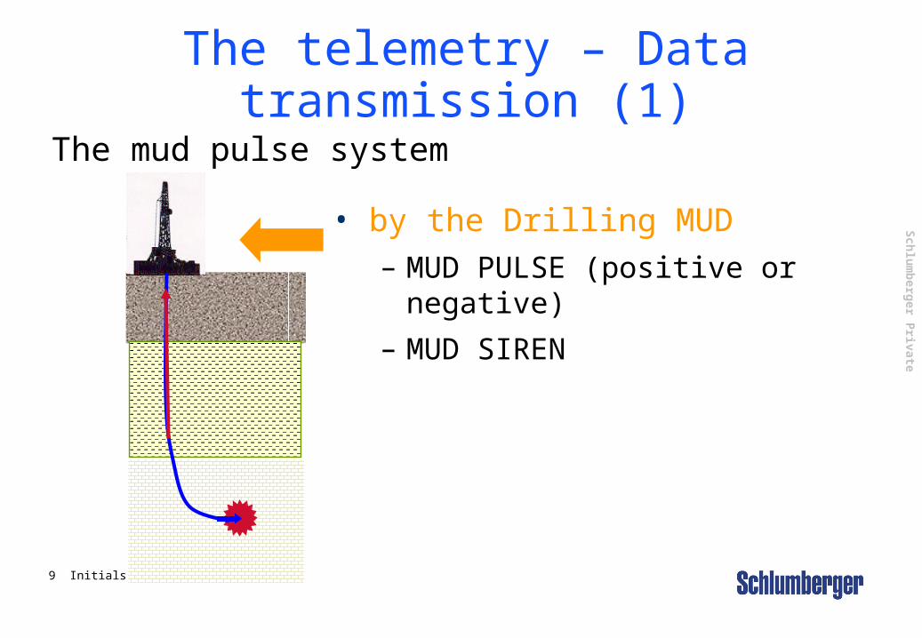
The telemetry – Data transmission (1)
The mud pulse system
• by the Drilling MUD – MUD PULSE (positive or
negative)
– MUD SIREN
Sch
lum
berg
er Private
10 Initials
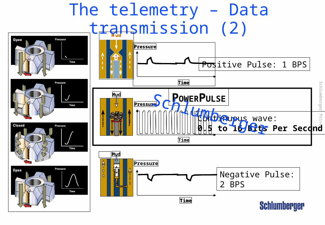
The telemetry – Data transmission (2)
MudMud
Pressure
Time
Pressure
Time
Mud
Time
Pressure
Time
Mud
PressurePressure
Time
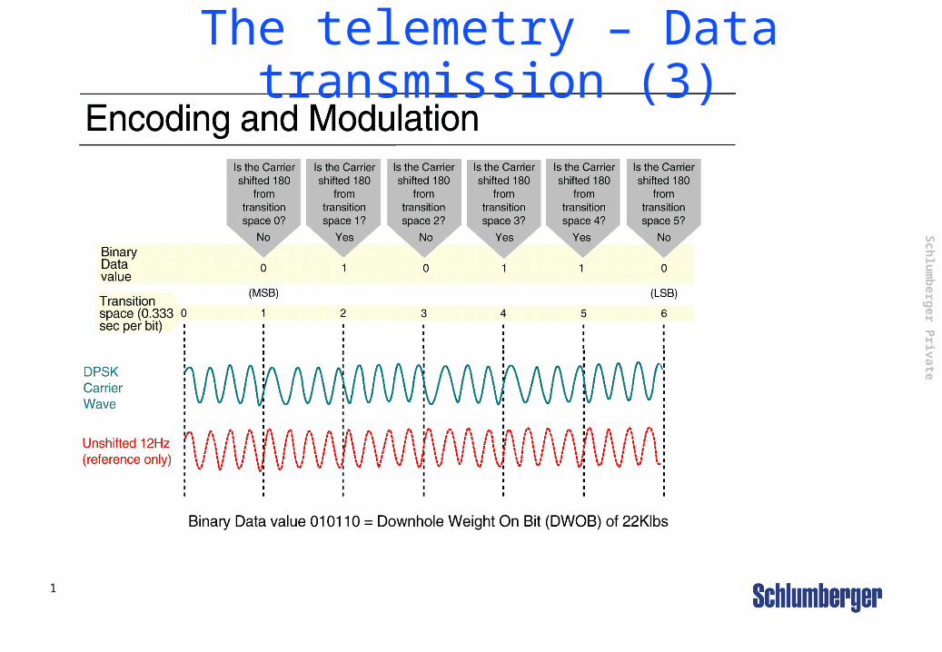
Positive Pulse: 1 BPS
Negative Pulse: 2 BPS
Continuous wave: 0.5 to 16 Bits Per Second
POWERPULSESchlumberger
Sch
lum
berg
er Private
11 Initials
The telemetry – Data transmission (3)
Sch
lum
berg
er Private
12 Initials
The telemetry – Data transmission (4)
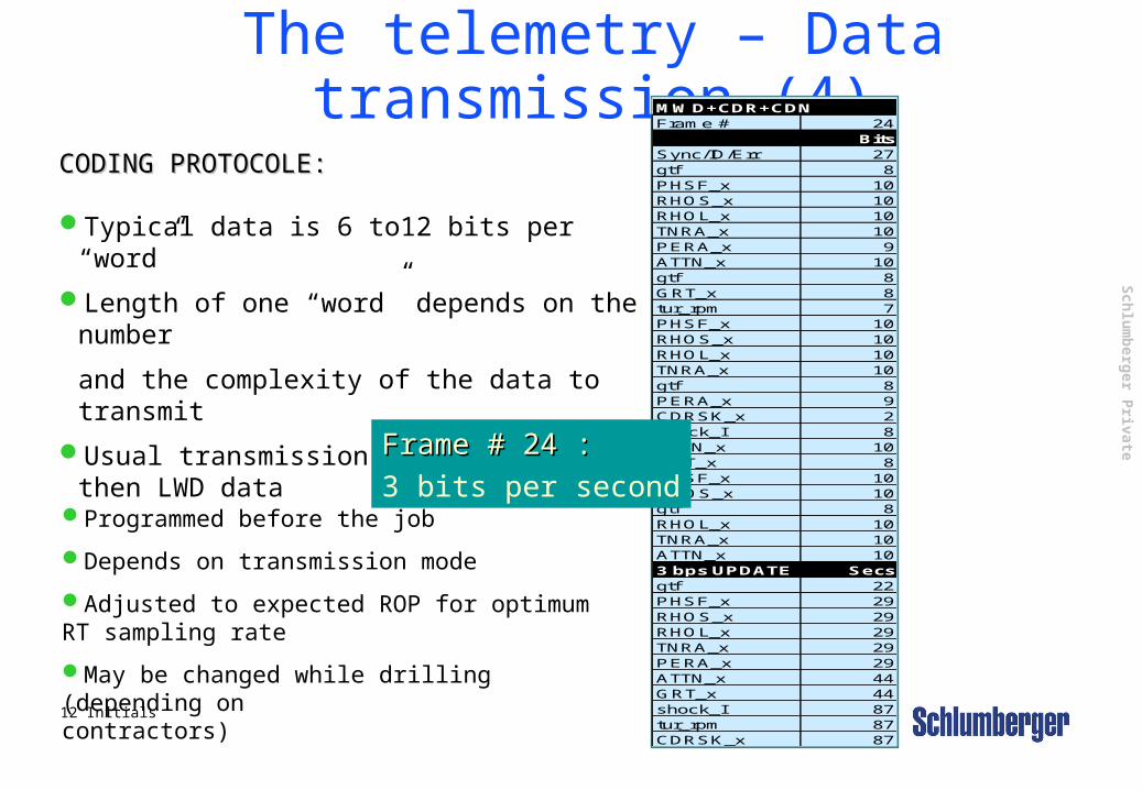
CODING PROTOCOLE:CODING PROTOCOLE:
Typical data is 6 to12 bits per “word”
Length of one “word” depends on the number
and the complexity of the data to transmit
Usual transmission priority is MWD then LWD data
MWD+CDR+CDNFrame # 24
BitsSync/ID/Err 27gtf 8PHSF_x 10RHOS_x 10RHOL_x 10TNRA_x 10PERA_x 9ATTN_x 10gtf 8GRT_x 8tur_rpm 7PHSF_x 10RHOS_x 10RHOL_x 10TNRA_x 10gtf 8PERA_x 9CDRSK_x 2shock_I 8ATTN_x 10GRT_x 8PHSF_x 10RHOS_x 10gtf 8RHOL_x 10TNRA_x 10ATTN_x 103 bps UPDATE Secsgtf 22PHSF_x 29RHOS_x 29RHOL_x 29TNRA_x 29PERA_x 29ATTN_x 44GRT_x 44shock_I 87tur_rpm 87CDRSK_x 87
Frame # 24 : Frame # 24 :
3 bits per secondProgrammed before the job
Depends on transmission mode
Adjusted to expected ROP for optimum RT sampling rate
May be changed while drilling (depending on contractors)
Sch
lum
berg
er Private
13 Initials
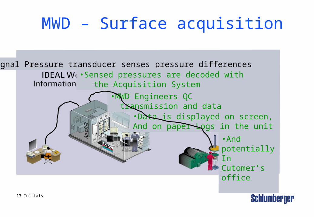
MWD – Surface acquisition
A signal Pressure transducer senses pressure differences•Sensed pressures are decoded with the Acquisition System
•MWD Engineers QC transmission and data
•Data is displayed on screen,And on paper Logs in the unit
•And potentially In Cutomer’s office
Sch
lum
berg
er Private
14 Initials
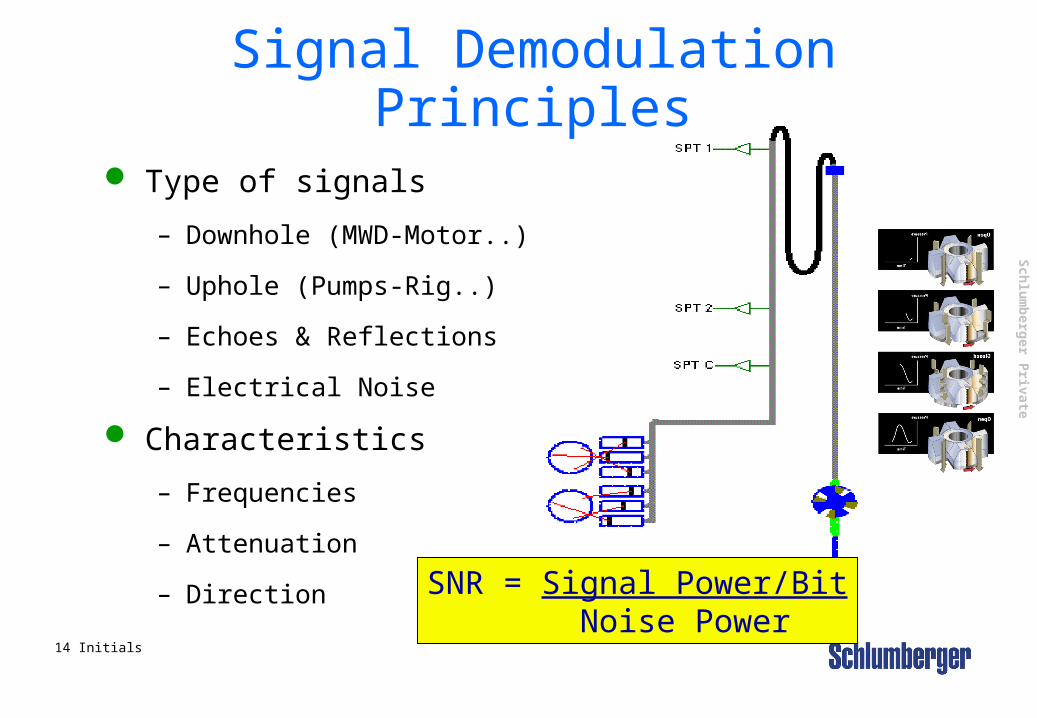
Signal Demodulation Principles
Type of signals
– Downhole (MWD-Motor..)
– Uphole (Pumps-Rig..)
– Echoes & Reflections
– Electrical Noise
Characteristics
– Frequencies
– Attenuation
– DirectionSNR = Signal Power/Bit
Noise Power
Sch
lum
berg
er Private
15 Initials
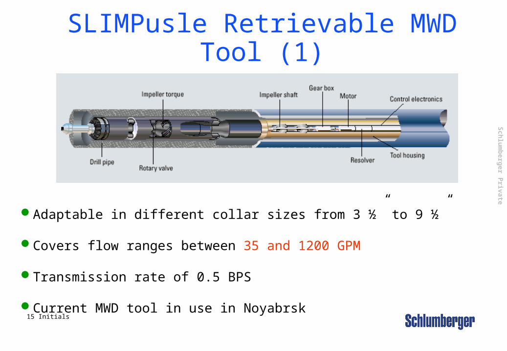
SLIMPusle Retrievable MWD Tool (1)
Adaptable in different collar sizes from 3 ½” to 9 ½”
Covers flow ranges between 35 and 1200 GPM
Transmission rate of 0.5 BPS
Current MWD tool in use in Noyabrsk
Sch
lum
berg
er Private
16 Initials
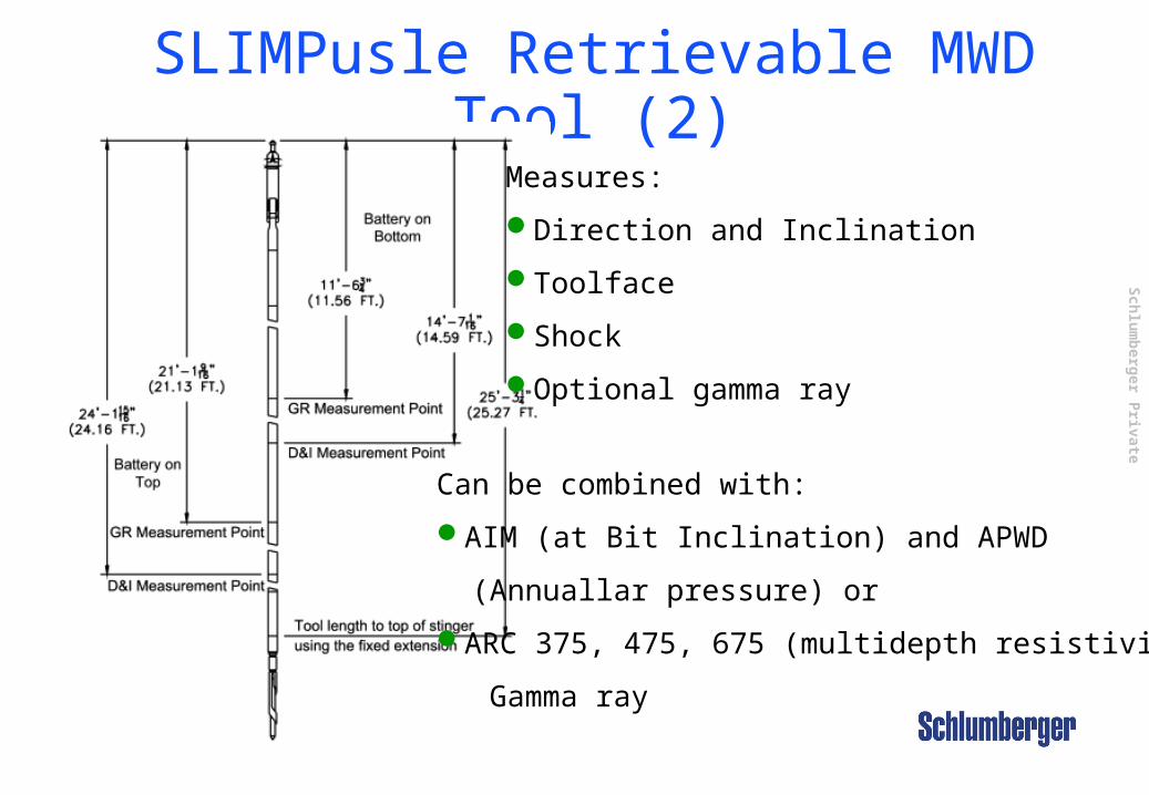
SLIMPusle Retrievable MWD Tool (2)Measures:
Direction and Inclination
Toolface
Shock
Optional gamma ray
Can be combined with:
AIM (at Bit Inclination) and APWD
(Annuallar pressure) or
ARC 375, 475, 675 (multidepth resistivity and
Gamma ray
Sch
lum
berg
er Private
17 Initials
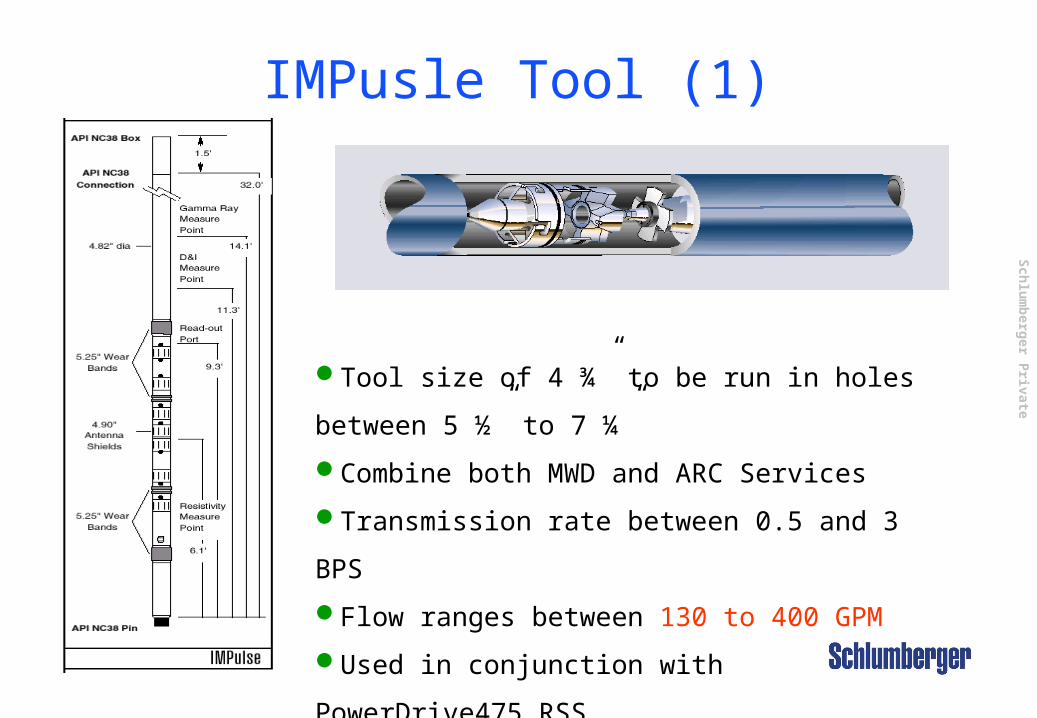
IMPusle Tool (1)
Tool size of 4 ¾” to be run in holes between
5 ½” to 7 ¼”
Combine both MWD and ARC Services
Transmission rate between 0.5 and 3 BPS
Flow ranges between 130 to 400 GPM
Used in conjunction with PowerDrive475
RSS
Sch
lum
berg
er Private
18 Initials
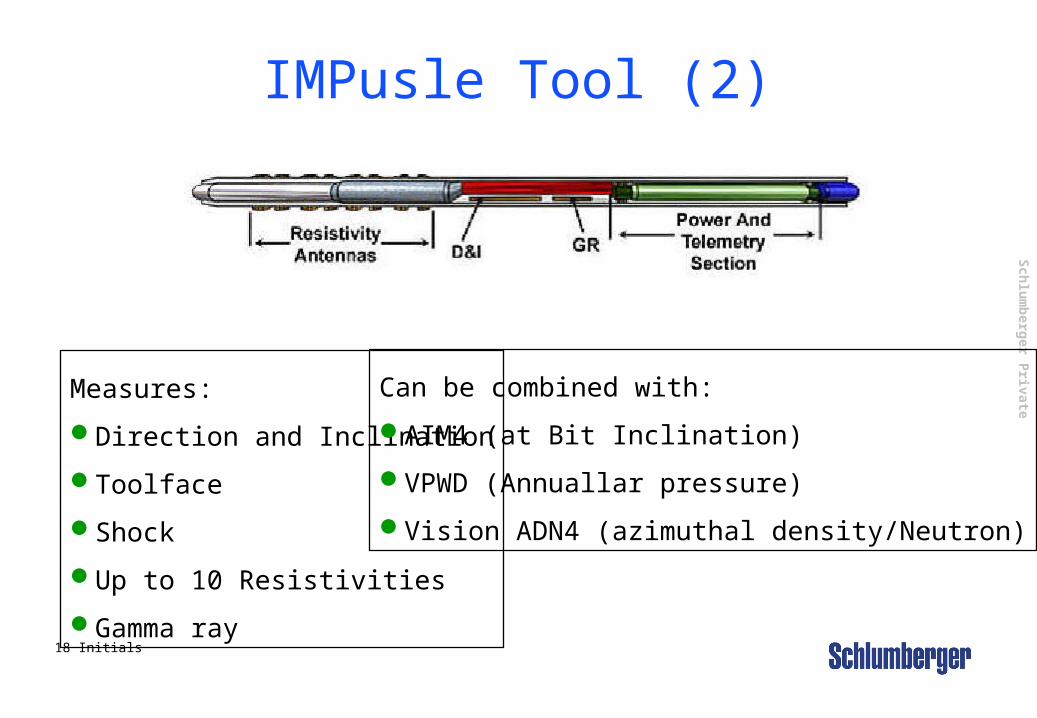
IMPusle Tool (2)
Measures:
Direction and Inclination
Toolface
Shock
Up to 10 Resistivities
Gamma ray
Can be combined with:
AIM4 (at Bit Inclination)
VPWD (Annuallar pressure)
Vision ADN4 (azimuthal density/Neutron)
Sch
lum
berg
er Private
19 Initials
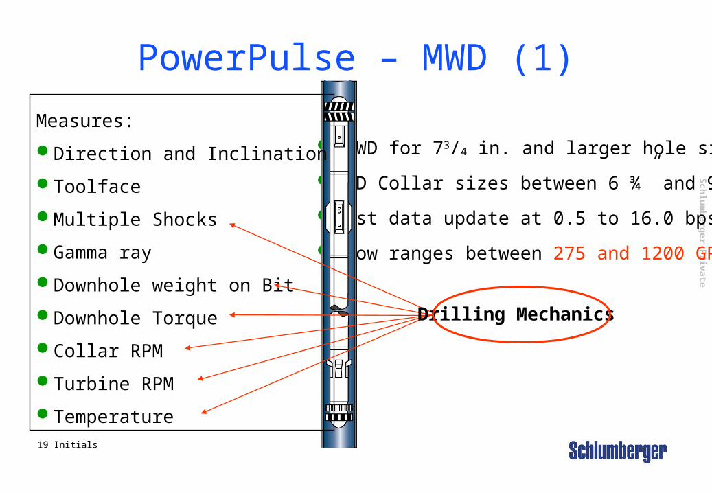
PowerPulse – MWD (1)
MWD for 73/4 in. and larger hole sizes
MWD Collar sizes between 6 ¾” and 9 ½”
Fast data update at 0.5 to 16.0 bps
Flow ranges between 275 and 1200 GPM
Measures:
Direction and Inclination
Toolface
Multiple Shocks
Gamma ray
Downhole weight on Bit
Downhole Torque
Collar RPM
Turbine RPM
Temperature
Drilling Mechanics
Sch
lum
berg
er Private
20 Initials
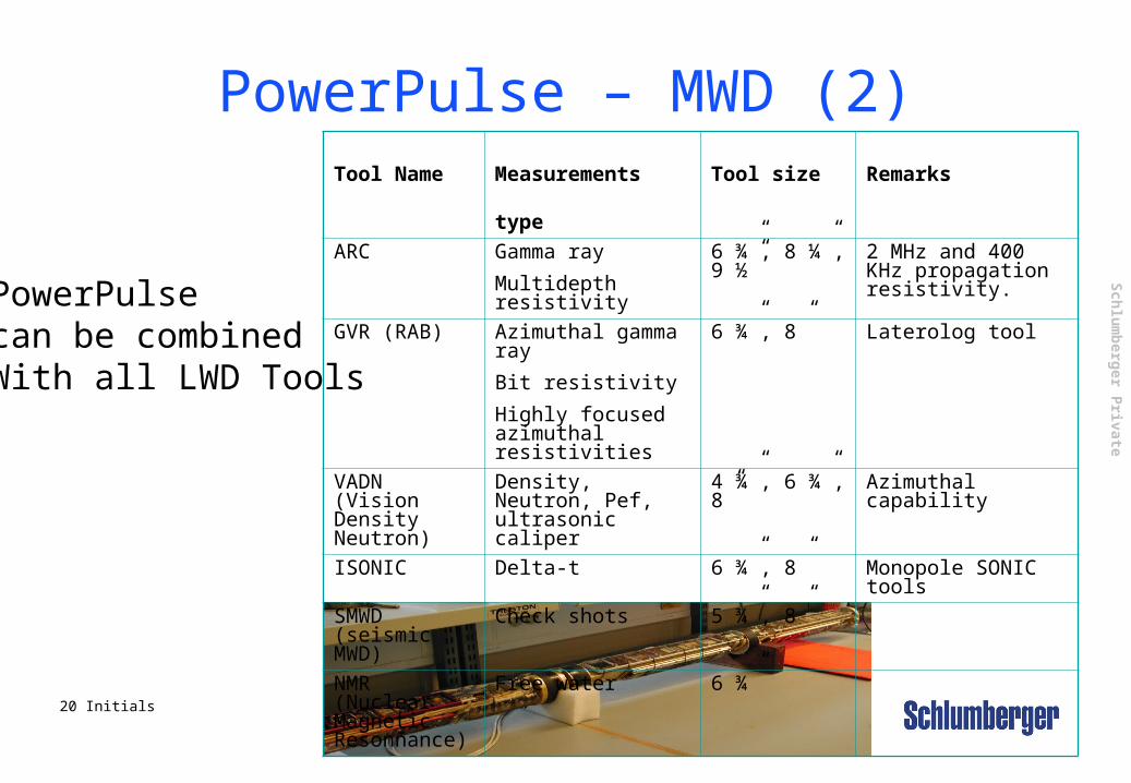
PowerPulse – MWD (2)Tool Name Measurements
type
Tool size Remarks
ARC Gamma ray
Multidepth resistivity
6 ¾”, 8 ¼”, 9 ½”
2 MHz and 400 KHz propagation resistivity.
GVR (RAB) Azimuthal gamma ray
Bit resistivity
Highly focused azimuthal resistivities
6 ¾”, 8” Laterolog tool
VADN (Vision Density Neutron)
Density, Neutron, Pef, ultrasonic caliper
4 ¾”, 6 ¾”, 8”
Azimuthal capability
ISONIC Delta-t 6 ¾”, 8” Monopole SONIC tools
SMWD (seismic MWD)
Check shots 5 ¾”, 8”
NMR (Nuclear Magnetic Resonnance)
Free water 6 ¾”
PowerPulse can be combinedWith all LWD Tools