schmidt model g5 taximeter installation instructions
TRANSCRIPT

170516 G5 Installation Manual V4.docx
SCHMIDT MODEL G5 TAXIMETER
INSTALLATION INSTRUCTIONS
Version 5, 18 July 2017
ContentsContentsContentsContents
1. Wiring................................................................................................................................ 3
2. Installing the GPS Unit ...................................................................................................... 4
3. Installing the 3G Communications Module ........................................................................ 4
4. Installing the Bracket and Mounting the Taximeter ............................................................ 5
5. Clearing the G5 Taximeter Memory .................................................................................. 7
6. Manually Calibrating the G5 Taximeter ............................................................................. 8
7. Setting up the 3G Communications Port and Printer Port .................................................. 8
8. Assigning the G5 Taximeter to an Operator ...................................................................... 9
9. Create or Modify Taximeter Configuration ....................................................................... 10
10. Create or Modify Driver Users ....................................................................................... 11
11. Post Installation Checklist ............................................................................................. 11
12.Technical Assistance ..................................................................................................... 12
2 170718 G5 Installation Manual V5.docx
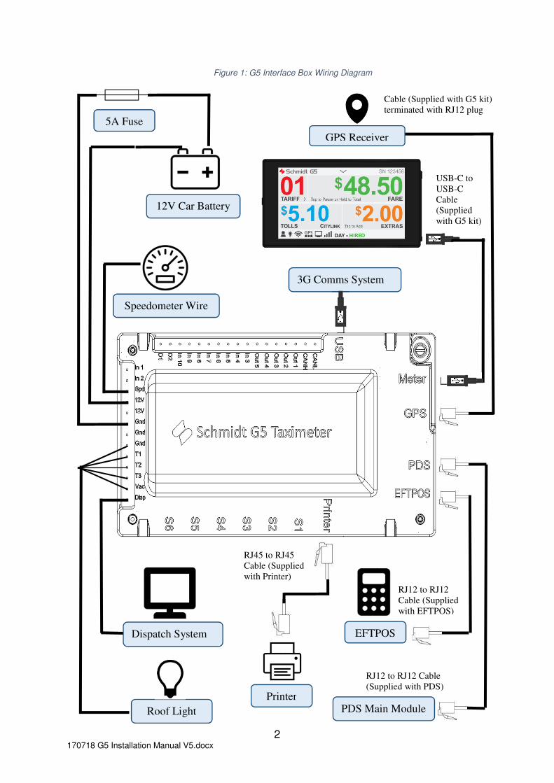
Figure 1: G5 Interface Box Wiring Diagram
EFTPOS
3G Comms System
RJ12 to RJ12
Cable (Supplied
with EFTPOS)
RJ45 to RJ45
Cable (Supplied
with Printer)
PDS Main Module
RJ12 to RJ12 Cable
(Supplied with PDS)
Roof Light
USB-C to
USB-C
Cable
(Supplied
with G5 kit)
Dispatch System
Cable (Supplied with G5 kit)
terminated with RJ12 plug
GPS Receiver
Speedometer Wire
Printer
5A Fuse
12V Car Battery
3 170718 G5 Installation Manual V5.docx
1. Wiring
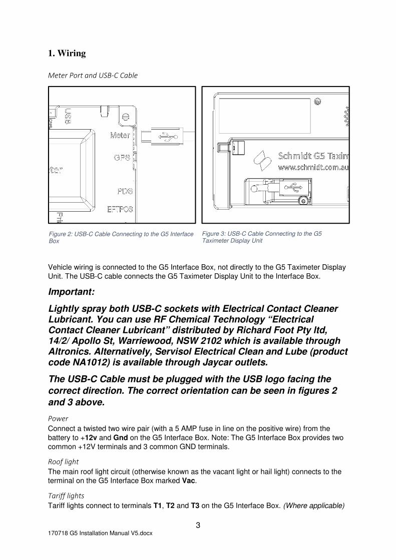
Meter Port and USB-C Cable
Vehicle wiring is connected to the G5 Interface Box, not directly to the G5 Taximeter Display
Unit. The USB-C cable connects the G5 Taximeter Display Unit to the Interface Box.
Important:
Lightly spray both USB-C sockets with Electrical Contact Cleaner Lubricant. You can use RF Chemical Technology “Electrical Contact Cleaner Lubricant” distributed by Richard Foot Pty ltd, 14/2/ Apollo St, Warriewood, NSW 2102 which is available through Altronics. Alternatively, Servisol Electrical Clean and Lube (product code NA1012) is available through Jaycar outlets.
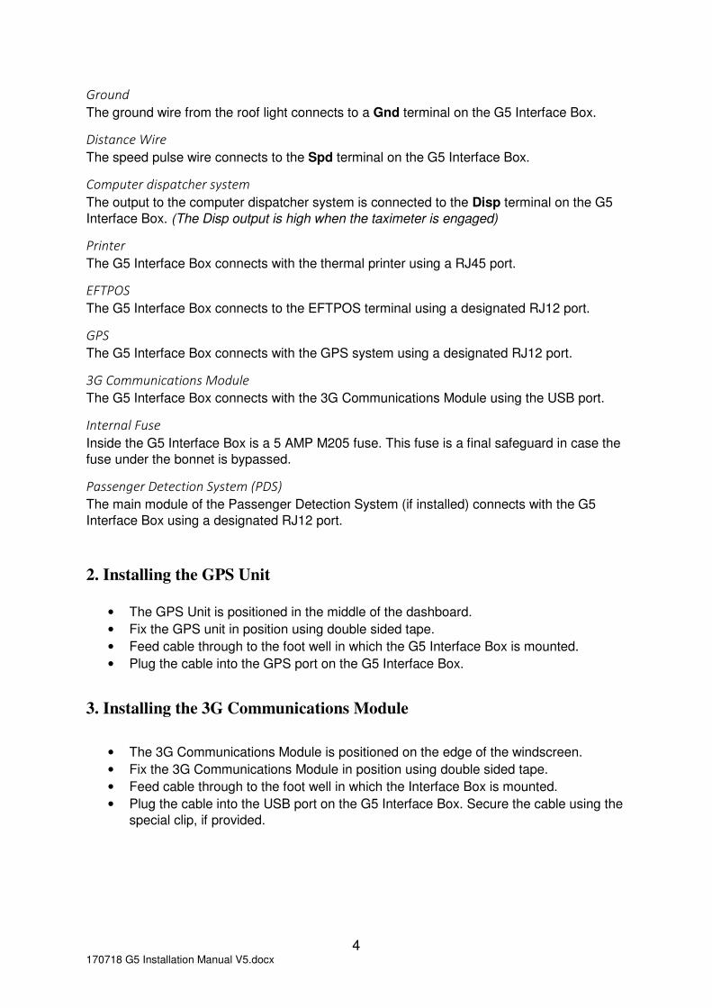
The USB-C Cable must be plugged with the USB logo facing the
correct direction. The correct orientation can be seen in figures 2
and 3 above.
Power
Connect a twisted two wire pair (with a 5 AMP fuse in line on the positive wire) from the
battery to +12v and Gnd on the G5 Interface Box. Note: The G5 Interface Box provides two
common +12V terminals and 3 common GND terminals.
Roof light
The main roof light circuit (otherwise known as the vacant light or hail light) connects to the
terminal on the G5 Interface Box marked Vac.
Tariff lights
Tariff lights connect to terminals T1, T2 and T3 on the G5 Interface Box. (Where applicable)
Figure 2: USB-C Cable Connecting to the G5 Interface Box
Figure 3: USB-C Cable Connecting to the G5 Taximeter Display Unit
4 170718 G5 Installation Manual V5.docx
Ground
The ground wire from the roof light connects to a Gnd terminal on the G5 Interface Box.
Distance Wire
The speed pulse wire connects to the Spd terminal on the G5 Interface Box.
Computer dispatcher system
The output to the computer dispatcher system is connected to the Disp terminal on the G5
Interface Box. (The Disp output is high when the taximeter is engaged)
Printer
The G5 Interface Box connects with the thermal printer using a RJ45 port.
EFTPOS
The G5 Interface Box connects to the EFTPOS terminal using a designated RJ12 port.
GPS
The G5 Interface Box connects with the GPS system using a designated RJ12 port.
3G Communications Module
The G5 Interface Box connects with the 3G Communications Module using the USB port.
Internal Fuse
Inside the G5 Interface Box is a 5 AMP M205 fuse. This fuse is a final safeguard in case the
fuse under the bonnet is bypassed.
Passenger Detection System (PDS)
The main module of the Passenger Detection System (if installed) connects with the G5
Interface Box using a designated RJ12 port.
2. Installing the GPS Unit
• The GPS Unit is positioned in the middle of the dashboard.
• Fix the GPS unit in position using double sided tape.
• Feed cable through to the foot well in which the G5 Interface Box is mounted.
• Plug the cable into the GPS port on the G5 Interface Box.
3. Installing the 3G Communications Module
• The 3G Communications Module is positioned on the edge of the windscreen.
• Fix the 3G Communications Module in position using double sided tape.
• Feed cable through to the foot well in which the Interface Box is mounted.
• Plug the cable into the USB port on the G5 Interface Box. Secure the cable using the
special clip, if provided.

5 170718 G5 Installation Manual V5.docx
4. Installing the Bracket and Mounting the Taximeter
The G5 is supplied with a universal mounting kit that will allow it to be mounted in a variety of
locations.
With each kit you will receive the following:
a. 1 x straight bracket
b. 2 x identical L shaped plastic brackets
c. 1 x M3 20mm slot head screw
d. 2 x G5 sealing screw
e. 4 x mounting screws
Step 1. AssembleStep 1. AssembleStep 1. AssembleStep 1. Assemble the Mounting Kit.the Mounting Kit.the Mounting Kit.the Mounting Kit.
• Remove the Mounting Panel from the G5 Taximeter if it is attached.
• Place four screws through the slit in the Mounting Panel and into the straight bracket
as shown in figure 4. Alternatively place two screws through the slit in the Mounting
Panel and into each of the L brackets as shown in figure 5.
Figure 4: G5 Mounting Panel Connected with a Straight Bracket
Figure 5: G5 Mounting Panel Connected with a L Bracket

6 170718 G5 Installation Manual V5.docx
SSSStep 2. Attachtep 2. Attachtep 2. Attachtep 2. Attach the the the the G5 G5 G5 G5 TaximTaximTaximTaximeter eter eter eter Display Unit Display Unit Display Unit Display Unit to the Mounting Kitto the Mounting Kitto the Mounting Kitto the Mounting Kit
• Ensure the G5 USB-C cable is plugged into the back of the G5 Taximeter Display
Unit.
• Attach the back panel to the G5 Taximeter Display Unit. The USB-C cable is fed
through the slot in the Mounting Panel
Step 3. Seal the Step 3. Seal the Step 3. Seal the Step 3. Seal the G5 Taximeter Display UnitG5 Taximeter Display UnitG5 Taximeter Display UnitG5 Taximeter Display Unit
• Insert the M3 x 20mm slot head screw into the right side of the G5 Taximeter Display
Unit.
If Manual Calibration or Passenger Detection System setup is required, they
must be done before sealing the G5 Taximeter Display Unit.
Figure 7: G5 Taximeter Display Unit Mounted using two L Brackets Figure 6: G5 Taximeter Display Unit Mounted using
Straight Bracket
Figure 9 G5 Taximeter sealing wire Figure 8: G5 Taximeter with sealing cover and screw Figure 10: Attach the Sealing Cover Figure 11: Seal the G5 Taximeter Display Unit

7 170718 G5 Installation Manual V5.docx
• Insert the Sealing Cover followed by the sealing screw into the left side of the
taximeter.
• Align the holes in the sealing screw to the holes in the sealing side cover. Pass a
sealing wire through the holes and apply a manual seal if this is required.
• Use mounting screws to attach the brackets to the car.
Step Step Step Step 4444. Seal the . Seal the . Seal the . Seal the G5 Taximeter Interface BG5 Taximeter Interface BG5 Taximeter Interface BG5 Taximeter Interface Box.ox.ox.ox.
• Ensure that the USB-C cable and the GPS are connected to the G5 Taximeter
Interface Box.
• Attach the G5 Taximeter Interface Box sealing cover.
• Insert the sealing screw aligning the holes of the screw to the holes of the sealing
cover. Pass a sealing wire through the holes and apply a manual seal if this is
required.
5. Clearing the G5 Taximeter Memory
• Remove the G5 Taximeter Display Unit sealing cover. This reveals the USB port.
• Insert the G5 Dealer Dongle into the USB Port.
• Tap Settings and wait for the Dealer Dongle to be validated. (You must have
communications for this step).
• Tap Clear Memory.
• Tap Yes to continue.
• Remove the G5 Dealer Dongle from the USB port.
This procedure will clear all the running totals including:
• Last Fare Main Data
• Last Fare More Data
• Current Shift Main Data
• Current Shift More Data
• Meter Totals Main Data
Figure 10: Attach the sealing cover Figure 11: Seal the interface box

8 170718 G5 Installation Manual V5.docx
• Meter Totals More Data
• All shift Job data.
The taximeter’s calibration, current time and current date will not be affected.
6. Manually Calibrating the G5 Taximeter
• Remove the G5 Taximeter Display Unit sealing cover. This reveals the USB port.
• Insert the G5 Dealer Dongle into the USB Port.
• Tap Settings and wait for the Dealer Dongle to be validated. (You must have
communications for this step).
• Tap Manual Calibration.
• At the start of a 1 km length of road, tap Press To Reset, this will reset the pulse
counter to 0.
• Drive the vehicle over the 1km length of road. The pulse counter will increment with
each speedometer pulse.
• At the completion of the 1km drive, set the calibration pulses per KM to the pulse
counter value using the number pad. You may need to use the delete arrow to
remove the old calibration value.
• Tap the tick to store the new calibration value.
• Remove the G5 Dealer Dongle from the USB port.
7. Setting up the 3G Communications Port and Printer Port
• In order to function correctly both the 3G Communications port and Printer port need
to be configured correctly.
• Remove the G5 Taximeter Display Unit sealing cover. This reveals the USB port.
• Insert the G5 Dealer Dongle into the USB Port.
• Tap Settings and hold for a few seconds. (This is called a long hold. You do not
require communications for this step).
• Scroll to the bottom of the list of Settings.
• Tap the APN button to set-up or edit the APN and Dialling Code for 3G
Communications.
• In Australia ensure that the APN is set to om2mOPTUS and that the Dialling Code is
set to *99***1#
• If you edit the APN or Dialling Code ensure that you do not add extra spaces before
or after your entries as this will invalidate the entries.
• In other countries, you will need to check the APN and Dialling Code with your local
dealer.
• Tap the PRINTER button to set-up or edit the printer port.
• Ensure that the PORT NUMBER is set to 3
• Ensure that the BAUD RATE is set to 38400
• Tap the down arrow in the centre of the top line of the display, to return to the Menu
screen.

9 170718 G5 Installation Manual V5.docx
8. Assigning the G5 Taximeter to an Operator
The G5 Taximeter must be assigned to an Operator. If the Operator is an existing customer
who is already registered on the G5 Server, the Taximeter may be assigned to that Operator
by a Dealer. If the Operator is not registered on the G5 Server, the Dealer needs to create
an account for that Operator.
1. Creating a new Operator account on the G5 Server as follows. You will need the
Operator’s full name, address, phone, ABN and valid email address. You will also
need the Registration Number of the taxi into which the Taximeter is to be installed.
a. Log into the G5 Website using your Dealer log-in
b. Click on Create or Manage Operator Companies. For convenience, we
consider every Operator to be an “Operator Company”, whether the Operator is a
company or not.
c. Click on Create New Operator Company
d. Complete the details for the New Operator Company:
i. The Operator Account is a name you assign to this Operator Company
ii. Enter the ABN and Full Company Name, which may simply be the
Operators proper name.
iii. Set the Default Zone correctly. If in doubt, please ask us.
iv. Enter the Data Retention Days.
v. Enter the required Contact Details. Be sure to accurately enter a Valid
Email Address as a password will be sent to that email address. Any
email address may only be used for a single account on the G5
Server.
vi. Click on the Save button when finished.
2. On the Dashboard, under Taximeter Management, click on Taximeter Set-up.
3. Click on the Serial No. of the Taximeter you wish to assign to an Operator.
4. Select the correct Jurisdiction, Tariff Set and Zone. If in doubt, please ask us.
5. Enter the ABN of the desired Operator Company and click the Locate button.
6. The name of the Zone and Operator Company should appear in the box labelled
Operator.
7. Select the required Taximeter Configuration. (This is explained below).
8. Select the Vehicle Type and enter the Vehicle Rego.
9. Unless otherwise required set the following:
a. PDS Status: Inactive
b. Duress Alarm Status: Inactive
c. Calibration Mode: Automatic
d. Operate Taxi Fares: Enabled
e. Audio: Enabled
10. Select the appropriate setting for the Sold/Hired Indicator.
11. Click on Save when finished.

10 170718 G5 Installation Manual V5.docx
9. Create or Modify Taximeter Configuration
Once an Operator Company has been created, the Dealer may Create or Modify a
Taximeter Configuration for that Operator Company. This Configuration sets basic
parameters for the way in which the taximeter will operate. The procedure is as follows:
1. Click on Create or Modify Taximeter Configuration.
2. If Taximeter Configurations have already been created for this Jurisdiction, they will be
listed in the table. If you want to modify one of those configurations, simply click on the
name of the Taximeter Configuration you want to modify.
3. If a new Taximeter Configuration is required, set the filter boxes to indicate the desired
Jurisdiction, Zone and Operator. Then click on Create New Taximeter
Configuration.
4. When the Taximeter Configuration screen opens, the available fields may be edited.
An explanation of these fields is as follows:
a. Make the Configuration Name meaningful so it reflects what you want to do.
b. In the Apply Discount Percentage field you can insert a value by which all
parameters on all tariffs will be discounted. For example, if you insert “10%”, all fares
will be discounted by 10%.
c. The Vacant Time Threshold is the value at which the vacant time between jobs will
be highlighted with a RED background colour, on the Jobs List.
d. The Vacant Kms Threshold is the value at which the vacant kms between jobs will
be highlighted in RED background colour, on the Jobs List.
e. The Night Shift Start Time and Night Shift End Time are used to define the
difference between night shifts and day shifts. Any shift started between these two
times will be considered a Night Shift. Any shift started outside of these times will be
considered a Day Shift.
f. Print Shift Report Automatically enables the Operator to select whether or not a
Shift Report is automatically printed on the miniature thermal printer at the end of
every shift.
g. If Mandate End of Shift Capture is selected, drivers will be required to enter data
into the G5 Taximeter at the end of every shift. That data will be uploaded to the G5
Server. If this option is not selected, drivers will not be required to enter any end of
shift data.
h. If Truncate Shift Report is selected, the Shift Report is printed without indicating the
end of shift taximeter totals.
i. The Driver Authentication Mode, enables the Operator to determine whether or not
drivers are required to log onto the taximeter before starting fares. If Open is
selected, anyone can log onto the taximeter at any time. If PIN is selected, drivers
are required to enter a PIN before being able to start a shift and take taxi fares. This
is the recommended setting. The Card option is reserved for future use.
j. The End of Shift Data Entry section enables an Operator to specify how the driver’s
pay-in is to be calculated.
k. The Operator Revenue Cap may be set to a Fixed value if required.
l. The Operator Revenue Percentage may be set to a Fixed Percentage of the Total
Shift Money, if required.
m. The Operator Fuel Percentage may be set to nominate the percentage of fuel costs
to be borne by the Operator.

11 170718 G5 Installation Manual V5.docx
n. If any of the Fuel items are set to “No”, the driver will not be prompted to enter data
for those items. If any of these items are set to “Variable” the driver will be prompted
to enter a value.
o. If the driver is required to enter Expenses or Non-cash items these fields should be
set to “Variable”.
p. In the Non-cash Payments table, the Operator can nominate that Drivers enter the
non-cash items in up to 6 different categories. The Operator can give these
categories any name which is useful, e.g. EFTPOS, Dockets, Subsidy Scheme, etc.
q. When the Save button is clicked this Taximeter Configuration will be saved on the G5
Server. The Operator may create an unlimited number of Taximeter Configurations,
and he/she may select which Taximeter Configuration is applicable to which
Taximeter at any time.
10. Create or Modify Driver Users
Any registered Operator may create or modify Driver Users by logging into his/her Operator
Account. The details are self-explanatory. Further information may be found in the G5
Website Manual.
11. Post Installation Checklist
1. Turn the taximeter on and check that the display starts up. If not, check the wiring to
the Interface Box +12V and GND terminals. Also check that the USB-C cable has been inserted correctly into both the Display Unit and Interface Box.
2. On the Menu screen, tap the roof light button on and off and check that the main roof
light turns on and off. You should also hear the feint click of a relay inside the Interface Box whenever you tap the roof light button on or off. If the roof light does not change state when tapping the roof light button, check the roof light circuits. Also check that the USB-C cable has been inserted into the Display Unit and Interface Box correctly.
3. Tap Memory, scroll to Meter Info, scroll to Pulse Counter (#7) and move the car a few
metres. The Pulse counter should increase. There will be roughly 2.5 to 5 pulses per metre of vehicle movement. If you do not see pulses accumulating in the Pulse Counter display, check the connection of the speedometer pulse wire to the Interface Box.
4. Check that at least one of the GPS circles on the bottom of the screen are filled with
black. This indicates that there is GPS reception. The car will need to be outdoors and it may take up to 5 minutes to receive reception after turning the taximeter on. If you do not detect GPS reception after 5 minutes, check that the GPS Unit cable is plugged correctly into the Interface Box.
5. With GPS reception, start a shift using any available test driver. Start a fare, move
the taxi a few metres to add some distance pulses, end the fare and print a receipt. The receipt will include the origin and destination suburb of the trip. Check that the suburb on the receipt is correct to confirm that the GPS is working. This also confirms that the printer is working.

12 170718 G5 Installation Manual V5.docx
6. Tap the Tariff display. If you can only select the tariffs programmed for that time of day, the Tariff selection is working,
7. Log onto the website and see if the shift started during test #5 above has been
logged on the Shifts page of the web portal.
• Click on My Shifts in the black panel at the top of the PC screen.
• Click on the Shift ID associated with the vehicle ID for the vehicle being tested.
If the Shift appears in the web portal, then 3G Communications is operational. Check that the shift has the correct:
• Start time
• Driver ID
• Vehicle ID
• Meter Serial Number
If you cannot see evidence that 3G Communications is working correctly, you may need to check or edit the APN or Dialling Code. Refer to Section 7, above.
8. Check that the following items in Meter Info are correct:
• Time and Date check (#1, 2 & 3)
• Calibration Mode (#4): Typically the default setting is AUTO
• Calibration (#5). The calibrations can be preset by arrangement. You can change it using the G5 Dealer Dongle provided, if necessary.
• Vehicle Rego (#8)
• Meter Serial No (#9) Check that this is the same number as the top of the taximeter screen.
• Fare Structure Name check (#13)
• Firmware version check (#20)
9. Check that the Printer is working correctly. If it is not working correctly, you may need to check or edit the PRINTER PORT or BAUD RATE. Refer to Section 7, above.
12.Technical Assistance
If you have any questions regarding installation of the G5 Taximeter please contact our
Technical Department on:
Phone: +61 3 9546 6990 or 1300 132 422
Fax: +61 3 9546 3993
Email: [email protected] or [email protected]