schneider 204
TRANSCRIPT

8/9/2019 Schneider 204
http://slidepdf.com/reader/full/schneider-204 1/34
.........................................................................
Cahier technique no. 204
LV protection devices and variablespeed drives (frequency converters)
J. SchonekY. Nebon
Collection Technique

8/9/2019 Schneider 204
http://slidepdf.com/reader/full/schneider-204 2/34
"Cahiers Techniques" is a collection of documents intended for engineersand technicians, people in the industry who are looking for more in-depthinformation in order to complement that given in product catalogues.
Furthermore, these "Cahiers Techniques" are often considered as helpful"tools" for training courses.They provide knowledge on new technical and technological developmentsin the electrotechnical field and electronics. They also provide betterunderstanding of various phenomena observed in electrical installations,systems and equipments.Each "Cahier Technique" provides an in-depth study of a precise subject inthe fields of electrical networks, protection devices, monitoring and controland industrial automation systems.
The latest publications can be downloaded from the Schneider Electricinternet web site.Code: http://www.schneider-electric.comSection: Experts' place
Please contact your Schneider Electric representative if you want either a"Cahier Technique" or the list of available titles.
The "Cahiers Techniques" collection is part of the Schneider Electric’s"Collection technique".
ForewordThe author disclaims all responsibility subsequent to incorrect use ofinformation or diagrams reproduced in this document, and cannot be heldresponsible for any errors or oversights, or for the consequences of usinginformation and diagrams contained in this document.
Reproduction of all or part of a "Cahier Technique" is authorised with theprior consent of the Scientific and Technical Division. The statement"Extracted from Schneider Electric "Cahier Technique" no. ....." (pleasespecify) is compulsory.

8/9/2019 Schneider 204
http://slidepdf.com/reader/full/schneider-204 3/34
no. 204
LV protection devices andvariable speed drives(frequency converters)
CT 204(e) updated May 2002
Jacques SCHONEK
Graduate engineer from ENSEEIHT with a doctorate in Engineeringfrom the University of Toulouse, he was involved in designingvariable speed drives for the Telemecanique brand from 1980 to 1995.He then became manager of the Harmonic Filtering group.He is currently responsible for Electrotechnical Applications andNetworks in the Advanced Design Office of Schneider Electric’selectrical distribution management.
Yves NEBON
He joined Merlin Gerin in 1969 and worked for 14 years in the lowvoltage design offices while continuing his professional training,gaining several diplomas and achieving the title of engineer. He thenheld a number of different positions in the Low Voltage Division.Since 1995 he has been responsible for the marketing, managementand development of the Merlin Gerin brand LV electrical distributionproduct ranges within Schneider Electric.

8/9/2019 Schneider 204
http://slidepdf.com/reader/full/schneider-204 4/34
Cahier Technique Schneider Electric no. 204 / p.2
8/9/2019 Schneider 204
http://slidepdf.com/reader/full/schneider-204 5/34
Cahier Technique Schneider Electric no. 204 / p.3
LV protection devices and variablespeed drives (frequency converters)
The purpose of this “Cahier Technique” is to explain the specific
phenomena observed in LV installations when there is an overload or
electrical fault in circuits equipped with variable speed drives.
Various recommendations are given to ensure that persons and property
are protected, and to provide optimum continuity of service.
Contents
1 Frequency converter type variable speed 1.1 Description p. 4drives for asynchronous motors 1.2 Need for appropriate protection devices p. 7
2 Devices providing protection against 2.1 Protection devices integrated in drives p. 8overcurrents 2.2 Protection devices external to drives p. 9
3 Protection of persons 3.1 Risks connected with insulation faults p. 11
3.2 Summary of earthing systems p. 12
3.3 Use of RCDs according to the earthing system p. 14
3.4 Earth fault protection devices integrated in drives p. 14
3.5 Insulation faults and variable speed drives p. 15
4 Protection devices to be used with drives (summary table) p. 19
5 Special phenomena 5.1 High-frequency leakage currents p. 20
5.2 Leakage currents on power-up p. 22
5.3 Fault at the drive output with a TT or TN system p. 23
5.4 Fault at the drive output with an IT system p. 25
5.5 Fault current with a DC component p. 26
6 Selection and installation recommendations 6.1 Selection of RCDs p. 28
6.2 Selection of PIMs p. 28
6.3 Prevention of malfunctions p. 29
Bibliography p. 30

8/9/2019 Schneider 204
http://slidepdf.com/reader/full/schneider-204 6/34
Cahier Technique Schneider Electric no. 204 / p.4
1 Frequency converter type variable speed drives forasynchronous motors
1.1 Description
Purpose
The purpose of “frequency converter” typevariable speed drives is to supply 3-phaseasynchronous motors in such a way as to obtainoperating characteristics which are radicallydifferent from those obtained in normal use(motors supplied directly from the power supply),with constant amplitude and frequency. The tablein figure 1 lists the advantages of these devices.
Principle
This consists of supplying the motor with avoltage wave with variable amplitude andfrequency, while keeping the voltage/frequencyratio more or less constant.This voltage wave is generated by an electronicpower device whose simplified schematic isshown in figure 4.
Asynchronous motor … in normal use … with variable speed drive
Starting current Very high, around 6 to 8 times the Limited in the motornominal current in rms value and (in general: around 1.5 times15 to 20 times in peak value the nominal current)
Starting torque Ts High and not controlled, around Around 1.5 times the nominal2 to 3 times the nominal torque Tn torque Tn and controlled for the
whole of the acceleration
Starting Sudden: its duration only depends on the Smooth, gradual and controlledcharacteristics of the motor and the driven (for example, linear speed ramp)load (resistive torque, inertia)
Speed Varies slightly according to the load Variation possible from zero(close to the synchronous speed Ns) up to a value greater thanthe synchronous speed Ns
Maximum torque Tm High, around 2 to 3 times the nominal High, available across the wholetorque Tn speed range (around 1.5 times
the nominal torque)
Electrical braking Relatively complex, requiring protection Easydevices and a special schematic
Reversing Easy only after the motor has stopped Easy
Risk of stalling Yes, with overtorque (resistive Notorque > Tm), or if voltage drops
Motor operation in the See fig. 2 See fig. 3torque-speed plane
Fig. 1 : comparison of the operating characteristics, showing the advantages of “frequency converter” type
variable speed drives.

8/9/2019 Schneider 204
http://slidepdf.com/reader/full/schneider-204 7/34
Cahier Technique Schneider Electric no. 204 / p.5
Fig. 2 : speed-torque diagram for a motor supplied
directly. The operating zone of the motor in the torque-
speed plane is limited to the green part of the curve.
Ts
Tm
T
Tn
0 1 (! / !s)
T
Tn
Tm
0 1 (! / !s)C
Fig. 3 : speed-torque diagram for a motor supplied via
a frequency converter. The operating zone of the motor in the torque-speed plane is shown in green.
The converter consists of:
c a single-phase or 3-phase diode rectifierbridge combined with a capacitor, forming a DCvoltage source (DC Bus),
c an inverter bridge, generally with IGBTs(Insulated Gate Bipolar Transistors), suppliedwith a DC voltage, which generates an ACvoltage wave with variable amplitude andfrequency using the “Pulse Width Modulation”(PWM) technique,
c a control unit providing the conductioncommands to the IGBTs according toinstructions given by the operator (runcommand, direction of operation, speed
reference, etc) and the measurement of theelectrical values (line voltage, motor current).
The PWM principle used in the inverter bridgeconsists of applying a series of voltage pulses to
the motor windings, whose amplitude is equal tothe DC voltage supplied by the rectifier. Thewidth of the pulses is modulated so that avariable amplitude AC voltage is created.The curves shown in figure 5 are examples ofphase-to-phase voltage and of current in one ofthe machine windings (assumingdelta-connected windings).
Fig. 4 : simplified schematic of a frequency converter.
M
Rectifier Inverter
Motor
Fig. 5 : voltage with PWM and current in a machine
winding.
0 0.005 0.01 0.015 0.02
t
(s)
I loadV load
8/9/2019 Schneider 204
http://slidepdf.com/reader/full/schneider-204 8/34
Cahier Technique Schneider Electric no. 204 / p.6
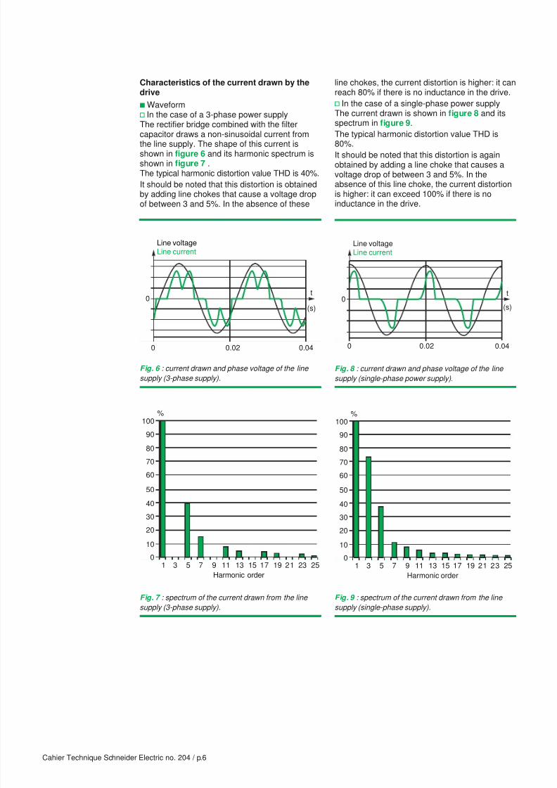
Characteristics of the current drawn by thedrive
c Waveformv In the case of a 3-phase power supplyThe rectifier bridge combined with the filter
capacitor draws a non-sinusoidal current fromthe line supply. The shape of this current isshown in figure 6 and its harmonic spectrum isshown in figure 7 .The typical harmonic distortion value THD is 40%.
It should be noted that this distortion is obtainedby adding line chokes that cause a voltage dropof between 3 and 5%. In the absence of these
Fig. 6 : current drawn and phase voltage of the line
supply (3-phase supply).
Fig. 7 : spectrum of the current drawn from the line
supply (3-phase supply).
0
0.020 0.04
Line voltageLine current
t
(s)
0
10
20
30
40
50
60
70
80
90
100%
1 3 5 7 9 11 13 15 17 19 21 23 25
Harmonic order
Fig. 8 : current drawn and phase voltage of the line
supply (single-phase power supply).
Fig. 9 : spectrum of the current drawn from the line
supply (single-phase supply).
0
0.020 0.04
Line voltageLine current
t
(s)
0
10
20
30
40
50
60
70
80
90
100%
1 3 5 7 9 11 13 15 17 19 21 23 25
Harmonic order
line chokes, the current distortion is higher: it canreach 80% if there is no inductance in the drive.
v In the case of a single-phase power supplyThe current drawn is shown in figure 8 and itsspectrum in figure 9.
The typical harmonic distortion value THD is80%.
It should be noted that this distortion is againobtained by adding a line choke that causes avoltage drop of between 3 and 5%. In theabsence of this line choke, the current distortionis higher: it can exceed 100% if there is noinductance in the drive.

8/9/2019 Schneider 204
http://slidepdf.com/reader/full/schneider-204 9/34
Cahier Technique Schneider Electric no. 204 / p.7
c Variation of the line current according to themotor operating pointSince the fundamental current drawn by thedrive is practically in phase with the voltage, thecurrent is proportional to the electric powerdrawn from the line supply. If we disregard theefficiency, this current is therefore proportional tothe mechanical power supplied by the motor.The mechanical power is equal to the product ofthe torque times the speed. Thus, at reducedspeed the mechanical power is low. As a result,the current drawn from the line supply by thedrive is low when the motor operates at lowspeed, even if the motor produces a high torqueand takes a high current.
Standard references
Two standards are particularly concerned withthe design of variable speed drives:
c IEC 61800-3 “Adjustable speed electricalpower drive systems - Part 3: EMC product
standard.”
c EN 50178 “Electronic equipment for use inpower installations”. Conformity to this standardauthorizes CE marking under the European “LowVoltage” directive.It should be noted that this standard also givesdetails for installing these products.
1.2 Need for appropriate protection devices
The characteristics described above, bothtechnological (electronic power circuits) andthose relating to the operation of the motorcombined with a drive, demonstrate the need forappropriate protection devices in order to makethe best use of such equipment.The creation of drives which incorporateelectronic technology enables a number of these
protection devices to be integrated at a veryreasonable cost.Of course, these protection devices do notreplace those that are required under existingregulations to be installed at the start of eachcircuit and which are thus “external” to the drives.Operation of all the protection devices used isdescribed in the following sections.

8/9/2019 Schneider 204
http://slidepdf.com/reader/full/schneider-204 10/34
Cahier Technique Schneider Electric no. 204 / p.8
2 Devices providing protection against overcurrents
The protection devices commonly used againstovercurrents (circuit-breakers or fuses) aremainly provided to deal with two situations:
c To protect an installation against any risk ofshort-circuit.
c To avoid the risks resulting from a circuitoverload or an operating current that exceeds
the capacities of the conductors (busbars andcables) and the control and protection equipmentVariable speed drive technology enables someof these functions to be provided electronically.
2.1 Protection devices integrated in drives
Motor overload protection
Modern variable speed drives protect the motoragainst overloads:
c by instantaneous limiting of the rms current toaround 1.5 times the nominal current,
c by continuously calculating the I2t, takingaccount of the speed (as most motors areself-ventilated, cooling is less efficient at lowspeed).
It should be noted that when a start circuit onlysupplies one motor and its drive, this motoroverload protection simultaneously protects allthe switchgear and wiring against overloads.
Protection against motor or line short-
circuits downstream of the drive
If there is a short-circuit between phases at thedrive output (at the motor terminals or anywhereon the line between the drive and the motor), theovercurrent is detected in the drive and ablocking order is sent very quickly to the IGBTs.The short-circuit current (see fig. 10 ) is brokenwithin a few microseconds, which protects thedrive. This very fleeting current is mainly providedby the filter capacitor used with the rectifier, andis therefore imperceptible in the power supply line.
Other protection devices integrated in drives
Drives have other self-protection functions against:
c Overheating of their electronic componentsthat could result in their destruction. A sensorplaced on the heatsink stops the drive when thetemperature exceeds a certain threshold.
c Line voltage dips: This protection is necessaryto avoid any malfunction of the control circuits
Fig. 10 : short-circuit downstream of the drive.
M
Rectifier Inverter
Motor
and the motor, as well as any dangerousovercurrent when the line voltage returns to itsnormal value.
c Overvoltages at the line supply powerfrequency: This avoids possible destruction oftheir components.
c Loss of a phase (for 3-phase drives): becausethe single-phase supply which replaces the3-phase supply triggers an increase of thecurrent drawn.
Operation of the integrated protection
devices
If there is a fault, all these devices lock the driveand bring the motor to a “freewheel” stop. Thepower supply is then cut by the line contactor (itsopening is controlled by a relay integrated in thedrive).

8/9/2019 Schneider 204
http://slidepdf.com/reader/full/schneider-204 11/34
Cahier Technique Schneider Electric no. 204 / p.9
2.2 Protection devices external to drives
In addition to the requirements described at thebeginning of this section, these devices forprotection against overcurrents are also designed
to operate if there is an internal fault in the drive(destruction of the rectifier bridge for example):the line protection device breaks the fault current.
Note: Although this device cannot normallyprotect the drive components, its automaticopening limits the consequences of such faults.
Location of the devices
The most common circuit layout for which theseprotection devices have been defined appears infigure 11 :
c with, at the start of the circuit, individualprotection against overcurrents often associatedwith a contactor,
c without a breaker device downstream of the drive.The functions of the various devices (circuit-breaker, contactor and drive) are shown on thisdiagram.
“Type 2 coordination” means that if there is ashort-circuit:
c no damage or loss of adjustment is permitted,
c the insulation must be maintained,c the motor combination must be able to operateafter the short-circuit has been removed,
c the risk of contact welding on the contactor ispermitted if these contacts can be separatedeasily.
If there is a short-circuit risk upstream of thedrive, in order to provide type 2 coordination, it isnecessary to refer to the coordination tablesprovided by the manufacturers of the protectiondevices placed upstream.
Note: With a drive, there is no current peak onpower-up, and therefore no particular stress
placed on the protection device.
Calculation of the circuit-breaker andcontactor rating
This is determined according to the line currentdrawn by the drive. It is calculated based on:
c the motor nominal mechanical power,
c the nominal supply voltage,
c the efficiency of the motor and the drive,
c a permissible continuous overload of 1.1 Tn atconstant torque and 1.05 Tn at variable torque,
c harmonics, since the current is not sinusoidal.The rms value of the current, depending on the
harmonic distortion, is obtained using theformula:
I Irms
THD= +1
21
thus, when THD = 40 %, Irms = 1.08 I1 .
Since the fundamental current I1 is practically inphase with the voltage, the typical value of thecurrent drawn by the drive, when it supplies amotor operating at its nominal point (constanttorque application), is calculated using theformula:
I I. .rmsmot
= "1 08 1 081 1
1mot
drive
x 1.1P
3U # #
Where:
Pmot: motor nominal power
U: phase-to-phase voltage
#mot: motor efficiency
#drive: drive efficiency
Fig. 11 : recommended diagram for overcurrent
protection.
M
Circuit breaker:c short-circuit protection,c isolation for maintenance.
Contactor:c automatic on-off,c power supply breaking inthe event of a fault.
Drive:c soft start,c variable speed control,c motor protection,c overload protection(wiring and switchgear).
Motor
These combinations (circuit-breaker, contactor anddrive) offered by manufacturers are called “motorcombinations”. Due to the protection devicesintegrated in the drives, these combinationsnaturally provide type 2 coordination if there is ashort-circuit downstream of the drive.

8/9/2019 Schneider 204
http://slidepdf.com/reader/full/schneider-204 12/34
Cahier Technique Schneider Electric no. 204 / p.10
c Example:
Motor rating: 15 kW
Line voltage: 400 V
#mot: 0.95
#drive: 0.97
giving: I
rms = 27.9 A
Two special cases
c Motors supplied in parallelIn this case the overload protection integrated inthe drive cannot protect each motor. This meansthat one of the motors could have an overload,although the current drawn by all the motorstogether does not exceed the drive nominalcurrent.The motors must therefore be protectedindividually by a thermal overload relay (seefig. 12 ).It is however recommended that the overload
protection integrated in the drive should remainactive, in order to protect the cables upstream.
c Integral drive overload protection disabledFor certain applications for which continuity ofoperation is essential, the drive overloadprotection can be disabled. The cables andswitchgear, which must be protected upstream,must therefore have an overload protectionassociated with the motor combinationcircuit-breaker (see fig. 13 ).Oversizing of the cable and the switchgear by20% is recommended in this situation.
Fig. 12 : overload protection of a number of motors
supplied by the same drive.
M
M
M
Circuit-breaker Contactor
Fig. 13 : integral drive overload protection disabled.
M
Circuit-breaker Contactor

8/9/2019 Schneider 204
http://slidepdf.com/reader/full/schneider-204 13/34
Cahier Technique Schneider Electric no. 204 / p.11
3 Protection of persons
3.1 Risks connected with insulation faults
An insulation fault, whatever its cause, presentsrisks for:
c the safety of persons (risk of electric shock),
c the safety of property (risk of fire or explosiondue to excessive localized temperature rise),
c the availability of the electrical power(disconnection of part of an installation in orderto eliminate the fault).
The standards and regulations concerning theprotection of persons identify two types of
dangerous contact and stipulate thecorresponding protection measures.
Direct contact
Persons coming into contact with live conductors(phase or neutral) or conductive parts that arenormally live (see fig. 14 ).Protection against this risk is usually provided byinsulating the live parts using barriers, screens orenclosures (in accordance with IEC 60364-4-41).These devices are of a preventive nature and arenot fool proof. To alleviate any risk, an additional,automatic break protection measure is used,consisting of the detection of any earth leakage
current which may circulate through a person,and which does not loop back to the source viathe live conductors. Its trip threshold is set at30 mA for AC current (IEC 60364-4-41) and60 mA for DC current.
Fig. 15 : indirect contact.Fig. 14 : direct contact.
N
PE
RB RA
If
Uf
NPE
RB RA
If
In the event of contact with a frame which isaccidentally energized (Uf) the danger threshold isfixed by the safety limit voltage UL .
Thus where:RA = earthing resistance of the installation frames,RB = earthing resistance of the neutral,
the operating threshold (I$n) of the protection devicemust be such that:
Uf = RA .I$n i UL
and then I$n i UL / RA.
(For more details, please refer to Cahier Techniqueno. 114)
Indirect contact
Persons coming into contact with conductivemetal frames, which are normally volt-free, andaccidentally become live. This energizing is theresult of failure of the insulation of a device or aconductor leading to an insulation fault (seefig. 15 ).This electrical risk depends on the contactvoltage that develops between the frame of thefaulty equipment and the earth or otherconductive metal frames located nearby.
Depending on the electrical connectionsbetween the live conductors, frames and earth,the standards provide different installationdiagrams for defining the protection devices tobe used. For further explanations see “CahierTechnique” no. 172.

8/9/2019 Schneider 204
http://slidepdf.com/reader/full/schneider-204 14/34
Cahier Technique Schneider Electric no. 204 / p.12
3.2 Summary of earthing systems
There are three types of earthing system,commonly known as neutral point connection, forLV networks. They differ according to whether or
not the neutral point of the voltage source isearthed and also the method used to connectthe frames (see fig. 16 ). The choice of theneutral point connection depends on theinstallation characteristics and the operatingconditions and requirements.
For further details see also the following“Cahiers Techniques”:
c No. 173 - Earthing systems worldwide andevolutions,
c No. 178 - The IT earthing system (unearthedneutral) in LV.
TT system
In this type of system, known as “directly earthedneutral”:
c the source neutral is connected to a separateearth connection from that of the frames,
c all frames protected by one breaking devicemust be connected to the same earthconnection.
This is typically the case with public distributionin France.
The TT system requires immediate breakingsince any insulation fault may present a risk ofelectrocution.
TN system
The principle of this system, known as “neutralconnection”, is that any insulation fault will
trigger a single-phase short-circuit betweenphase and neutral. Immediate breaking is alsoessential and this system allows the use of theusual overcurrent protection devices to protectagainst insulation faults. In this type of system:
c the LV neutral point of each source isconnected directly to earth,
c all frames in the installation are earthed (andthus connected to neutral) via a protective earthconductor :
v PE separate from the neutral conductor; this isthe TN-S system,
v or common PEN with the neutral conductor;this is the TN-C system.
Note: The TN-C system is not recommended forsupplying electronic devices due to the possiblecirculation of harmonic currents in the neutralconductor that is also the protective earth.
IT system
In this type of system known as “unearthedneutral”:c The transformer neutral is:v either isolated from the earth (unearthed neutral),v or earthed via a high impedance(impedance-earthed neutral),
Directly earthed neutral (TT) Neutral connection (TN-C)
: Permanent insulation monitor.
Neutral connection (TN-S)Unearthed neutral (IT)
123
N
123
PEN
123NPEPE
PE
123N
RB RA
RB
RB
RB
Fig. 16 : the three standard types of earthing system.

8/9/2019 Schneider 204
http://slidepdf.com/reader/full/schneider-204 15/34
Cahier Technique Schneider Electric no. 204 / p.13
c all frames in the installation are connected toone another and earthed.
In the IT system, the first insulation fault doesnot require breaking to take place, whichenables the installation to continue to operatenormally. However, this fault must be detected,signaled and then repaired before a secondinsulation fault occurs on another live conductor,which would then require an immediate trip.This rule gives the IT system the best continuityof service (see also “Cahier Technique” no. 178).
Need for special detection methods
The value of the insulation fault current betweenphase and earth (in common mode) depends onthe earthing system. Its value is often too low tobe detected and eliminated by conventionalovercurrent protection devices (thermal ormagnetic protection of a circuit-breaker), as isthe case with the TT and IT systems.
Two devices are designed particularly forprotecting persons: Residual Current Devices -RCDs - and Permanent Insulation Monitors -PIMs -.
c Residual Current Devices
v Principle of RCDsThis is illustrated in figure 17.If there is no insulation fault, the algebraic sumof the currents in the live conductors is zero andthe toroid is not subjected to any magnetomotiveforce.
If there is an insulation fault, this sum is nolonger zero and the fault current creates a
magnetomotive force in the toroid that generatesa current in its coil. If the current exceeds a fixedthreshold for a period longer than the optionaltime delay, an opening command is transmittedto the breaking device.
For further details, see “Cahier Technique”no. 114: “Residual current devices in LV”.
Wave shaping
Threshold
Time delay
Actuator
% I & 0
v Types of RCDStandard IEC 60755 distinguishes three types ofresidual current protection device:AC: For sinusoidal AC currentsA: For AC currents with a DC component (seefig. 18 ). These devices are suitable fordetection of rectified single-phase currents.B: For DC currents. These devices are suitablefor all types of current and are necessary, inparticular, for rectified 3-phase currents.
c PIMsThe principle of a PIM consists of injecting anAC or DC voltage between the line supply andthe earth (see fig. 19 ). The measurement of thecurrent crossing the monitor is used to calculatethe insulation resistance when this is a DCcurrent, and that of the line supply/earthimpedance when this is an AC current.These measurements associated with thresholddevices authorize different alarms, for examplethat for the gradual reduction of insulation for thepurpose of planned maintenance, or for an earthfault requiring rapid intervention (before thesecond fault).
6 mA
' = 90°
' = 135°
Fig. 17 : principle of the RCD.
Fig. 18 : waveforms which characterize type A RCDs.
Fig. 19 : principle of a PIM.
PE
Measurement
Measurement
current generatora
Installation
insulation
(Rf)
Measurement current
Threshold ( time delay
( alarm

8/9/2019 Schneider 204
http://slidepdf.com/reader/full/schneider-204 16/34
Cahier Technique Schneider Electric no. 204 / p.14
3.3 Use of RCDs according to the earthing system
“Cahier Technique” no. 172: “Earthing systemsin LV” covers this subject in greater depth.
For all earthing systems
RCDs are used as additional protection againstthe risks of direct contact. In certain countriesthey are even compulsory upstream of i 32 Apower sockets with a i 30 mA trip threshold (forexample, in France, according to standardNF C 15-100 §532.26).RCDs with a sensitivity less than or equal to500 mA (IEC 60364, section 482) are alsorecommended for monitoring electrical supplycircuits in areas where there is a risk of fire.
TT system
The use of RCDs is the only method of detecting
low fault currents. In fact, the impedance of afault is not known with certainty and may be high(the load frames have separate earth connectionsand are not always connected to one another).
TN-S or TN-CS system
Using RCDs avoids the need to check the valueof the current if there is a fault.
They also control breaking of the circuits whenthe fault current, limited by a very long cable, isinsufficient to activate the overcurrent protection
devices. The trip threshold of the RCDs maythen be high (low sensitivity), from a few amps totens of amps.
Note: According to IEC 60364:
c a residual current device should not be used ina TN-C system,
c when a residual current device is used in aTN-C-S system, a PEN conductor should not beused downstream.
IT system
In an IT system, RCDs are used in the followingtwo situations.
c If the short-circuit current (at the 2nd fault) maynot be sufficient to activate protection againstfaults between phases, for example on feederssupplying loads which are a long distance away.
c For groups of receivers connected to earthindividually (groups of frames not connected toone another).
3.4 Earth fault protection devices integrated in drives
If the line supply has a TN system, a faultbetween a drive output and earth causes a
significant overcurrent due to the interconnectionof the frames (see fig. 20 ).As with a short-circuit between phases, thisovercurrent is detected and a blocking commandis sent to the IGBTs. However, in this situation
Fig. 20 : earth fault at the output.
Rectifier Inverter
Motor
N
PERB
If
M
the fault current circulates in the power supplyline for a very short time (a few hundred
microseconds).The integrated protection device then intervenes.The drive is electrically isolated by the openingof the line contactor. This device does notprotect persons against indirect contact under all

8/9/2019 Schneider 204
http://slidepdf.com/reader/full/schneider-204 17/34
Cahier Technique Schneider Electric no. 204 / p.15
Downstream of the drive Drive output voltage
On the DC bus Rectified line voltage
3.5 Insulation faults and variable speed drives
Direct contact
There are a number of possible direct contactsituations on circuits containing variable speeddrives (see fig. 21 hereafter and fig. 22 next page).c TT and TN-S systems
Fig. 21 : voltages present in the event of direct contact with TT and TN-S systems.
circumstances. In fact, the impedance of thefault may limit the current to a value that is belowthe drive’s protection threshold. This is generallythe case with the TT system. A 300 mA RCD istherefore necessary.
In the case of an IT system, the first fault doesnot cause current to circulate and the drivecontinues to operate normally.
An additional protection device, in the event offailure of other protection measures againstcontact or carelessness by users, can beprovided upstream of the drive using an RCDwith a 30 mA threshold.
Risk of direct contact Contact voltage Additionalprotection
Upstream of the drive Phase - neutral voltage 30 mA RCD
M
A
M
B
M
C

8/9/2019 Schneider 204
http://slidepdf.com/reader/full/schneider-204 18/34
Cahier Technique Schneider Electric no. 204 / p.16
Drive output voltage
c IT system with a first insulation fault present onthe line supply
Fig. 22 : various situations specific to a line supply with an IT system which has an insulation fault and a person in
direct contact.
Risk of direct contact Contact voltage Additional
protectionRectified line voltage No automatic break
protection possible
In the three situations specific to the IT systemshown in figure 22, no automatic breakprotection can be applied: the fault currentcannot be distinguished from the normal
operating current. This underlines theimportance that installers must give to the wiringof these machines in order to ensure the basicprecaution, i.e. insulation of live parts.
M
A
M
B
C
M

8/9/2019 Schneider 204
http://slidepdf.com/reader/full/schneider-204 19/34
Cahier Technique Schneider Electric no. 204 / p.17
Notes:
v The same is found for each of these situationswhen the two faults (insulation and directcontact) are swapped.
v When a number of drives are powered via the
same line supply, the DC buses of the differentdrives can be considered as being at the samevoltage. Faults on different drives therefore havethe same consequences as if they were locatedon one drive.
Fig. 23 : various insulation faults with TT and TN-S systems.
Situation Effect… (risk…) Relevant protection Relevant
with a TT system protection with a
TN-S system
Overcurrent RCD Overcurrent
upstream of the drive protection placed
upstream
Overcurrent across RCD immune to
a diode of the passage of DC
rectifier bridge. The current
fault current is a
rectified current.
(Risk of irreparable
damage)
Overcurrent across Internal in the drive Internal in the drive
a diode of the or orrectifier bridge and RCD overcurrent
an IGBT. protection placed
(Risk of irreparable upstream, but a
damage depending very long cable
on the type of downstream of the
“short-circuit” drive may mask the
protection integrated fault, and an RCD
in the drive) is therefore
recommended
M
A
M
C
B
M
Indirect contact
c TT and TN-S systems
The indirect contact situations are shown infigure 23 .
c IT system
With this system the presence of twosimultaneous faults must be taken into account.The table in figure 24 gives the various possiblefaults and their consequences.

8/9/2019 Schneider 204
http://slidepdf.com/reader/full/schneider-204 20/34
Cahier Technique Schneider Electric no. 204 / p.18
Fig. 25 : positioning of RCDs in an IT system to protect
two circuits with separate earth connections.
Fig. 24 : various situations with two dead shorts or low impedance faults on an IT system.
Situation Effect… (risk…) Relevant protection
Overcurrent upstream of the Overcurrent protection placeddrive upstream
Overcurrent across a diode of Overcurrent protection placedthe rectifier bridge upstream(Risk of irreparable damage)
Overcurrent across a diode of Internal in the drivethe rectifier bridge and an orIGBT (Risk of irreparable overcurrent protection placeddamage depending on the upstream, but a very longtype of “short-circuit” cable downstream of the
protection integrated in the drive may mask the fault.drive)
Short-circuit on the DC bus Overcurrent protection placed(Risk of irreparable damage upstreamto the rectifier bridge)
Short-circuit at the terminals Internal in the driveof an IGBT (Risk of irreparable ordamage to the opposite IGBT overcurrent protection placeddepending on the type of upstream“short-circuit” protectionintegrated in the drive)
Overcurrent at the drive output Internal in the drive
M
A
M
B
M
D
M
C
M
E
M
F
M
MPIM
c Special case of motors supplied via twoseparate circuits each containing a drive, wherethe frames have separate earth connections.
When an installation supplies a number ofdevices that are a long way away from oneanother, the load frames are often connectedwith separate earth connections. The impedanceof the circuit through which the fault current runsis thus increased by the resistance of the twoearth connections concerned. The conditionrequired for the protection of persons(compliance with maximum breaking times) canno longer be met by the short-circuit protectiondevices.
The usual solution, which is very simple both todesign and install, is to use RCDs (see “CahierTechnique” no. 178) placed at the start of each
circuit containing a separate earth connection(see fig. 25 ). These RCDs must not bedisturbed by the passage of a DC component.
8/9/2019 Schneider 204
http://slidepdf.com/reader/full/schneider-204 21/34
Cahier Technique Schneider Electric no. 204 / p.19
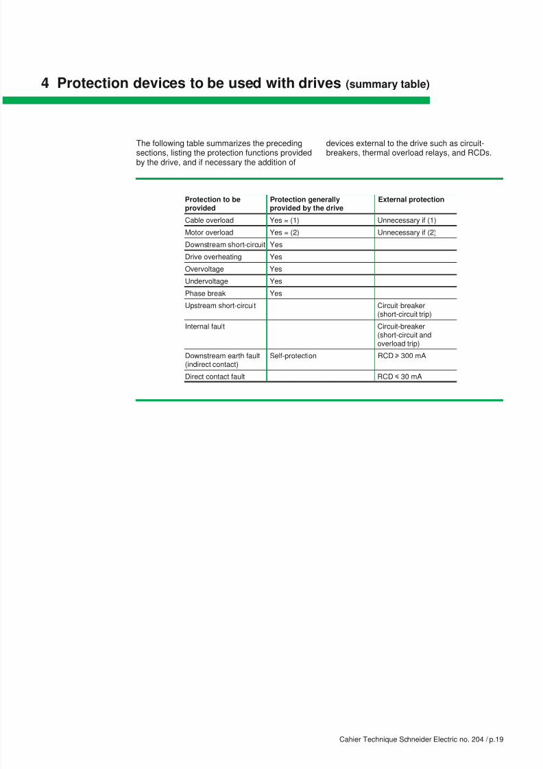
4 Protection devices to be used with drives (summary table)
Protection to be Protection generally External protectionprovided provided by the drive
Cable overload Yes = (1) Unnecessary if (1)
Motor overload Yes = (2) Unnecessary if (2)
Downstream short-circuit Yes
Drive overheating Yes
Overvoltage Yes
Undervoltage Yes
Phase break Yes
Upstream short-circuit Circuit-breaker(short-circuit trip)
Internal fault Circuit-breaker(short-circuit andoverload trip)
Downstream earth fault Self-protection RCD u 300 mA(indirect contact)
Direct contact fault RCD i 30 mA
The following table summarizes the precedingsections, listing the protection functions providedby the drive, and if necessary the addition of
devices external to the drive such as circuit-breakers, thermal overload relays, and RCDs.

8/9/2019 Schneider 204
http://slidepdf.com/reader/full/schneider-204 22/34
Cahier Technique Schneider Electric no. 204 / p.20
5 Special phenomena
The purpose of this section is to analyze thespecial phenomena connected with the operation
of frequency converters, which affect RCD andPIM protection devices.
5.1 High-frequency leakage currents
The voltage waveform generated by the drive,and in particular the presence of transientvoltage fronts generated by switching of theIGBTs, causes high-frequency leakage currentsto circulate in the power supply cables.
Flows
These voltage fronts are applied to the differentcapacitances in the circuit (see fig. 26 ):Cc: capacitance of the IGBT components betweenconductors and enclosure connected to earth,Cm: capacitance between the motor windingsand earth (depending on the motor rating),Cr: capacitance between the line supply andearth (short-circuited if the neutral is connectedto earth),Cs: capacitance between the output conductorsand earth (depending on the type and length ofthe cables),Cy: interference suppression capacitance at thedrive input.
Fig. 26 : capacitances in the circuit.
Fig. 27 : circulation of high-frequency leakage
currents.
Currents therefore circulate across thesecapacitances. The most significant are shown infigure 27 .
Drive
Cr CcCy CsCm
Cy Cs
Characteristics
These currents may reach an instantaneousvalue of several amps and an rms value ofseveral dozen or several hundred milliamps.The spectrum and amplitude of these currentsdepend both on the PWM frequency (between1 and 20 kHz) and the installationcharacteristics:c power supply: line impedance, earthingsystem,c type and length of the motor cable (shielded,not shielded, protective earth),c motor rating,The shape and spectrum of the HF currents atthe drive input (when there is no fault), for aPWM at 4 kHz, are shown in figures 28 and 29 .

8/9/2019 Schneider 204
http://slidepdf.com/reader/full/schneider-204 23/34
Cahier Technique Schneider Electric no. 204 / p.21
Fig. 28 : high-frequency leakage currents.
Fig. 29 : spectrum of the leakage current.
0.0 0.020.01 (s)
(A)
0.3
0.2
0.1
0
- 0.1
- 0.2
- 0.3
0.06
0.05
(A)
0.04
0.03
0.02
0.01
0 5 (kHz)10 151

8/9/2019 Schneider 204
http://slidepdf.com/reader/full/schneider-204 24/34
Cahier Technique Schneider Electric no. 204 / p.22
Their effect:risk of disturbance of RCDs
c Undesired trippingThese currents may cause malfunctioning of theresidual current devices (RCD) when they flow
through conductors surrounded by themeasurement toroid. The measurement of theresidual current may therefore be disturbed, inparticular when the drive – motor connectioncable is very long and/or the capacitancesbetween phases and earth are high (seefig. 30 ).
Fig. 30 : disturbance of an RCD by high-frequency
leakage currents.
Fig. 31 : RCD integrating filtering of HF currents
(Vigirex RH99M and RH99P – Merlin Gerin brand).
Solution
The measurement device must therefore includea filtering circuit so that only the low-frequencycomponent of the signal is taken into account(see fig. 31 ).
Additional precautions, given at the end of this“Cahier Technique”, may be necessary in certainextreme situations.
5.2 Leakage currents on power-up
Origin
Capacitors are generally placed at the input of
frequency converters to provide them withimmunity from the HF interference present onthe line supply and reduce their HF emissions.Their capacitance is around 10 to 100 nF.These capacitors are responsible for residualcurrents (see fig. 32 ) at power-up and duringnormal operation.
Their effect: risk of undesired tripping
For a device that is operating normally, thesecurrents are low (from 0.5 to 3.5 mA). However,in an industrial device that contains a number ofdrives, they can cause undesired tripping of RCDs.
Solution
This is the responsibility of the equipmentmanufacturer or the installer. It consists of limitingthe number of drives supplied by the same RCD.
Fig. 32 : leakage current flowing through the input
capacitors of devices (dotted lines).
N
Device withcapacitive filter
Modular type
Distribution board type

8/9/2019 Schneider 204
http://slidepdf.com/reader/full/schneider-204 25/34
Cahier Technique Schneider Electric no. 204 / p.23
5.3 Fault at the drive output with a TT or TN system
Risk of electrocution
The fault current contains a component at thePWM frequency and HF currents created by the
oscillations of the stray capacitances, but thedangers of HF currents are not widely known.Document IEC 60479-2 provides information inparticular on the variation of the threshold ofcardiac fibrillation.
This curve (see fig. 33 ) shows that thefrequency factor, which is the ratio of the currentat frequency f to the current at 50/60 Hzfrequency when considering the samephysiological effect, increases with thefrequency. It therefore permits a higher tripthreshold for current frequencies higher than50 Hz. This threshold variation is achievedtechnically by filtering.
If the impedance of this insulation fault is high,the overcurrent protection threshold may not bereached, and an RCD must therefore be fitted to
provide this protection.As already explained, correct operation of anRCD depends on the fault currents passingthrough its toroidal sensor, thus in this examplethese currents are not perfectly sinusoidal. Thewaveform of the zero-sequence fault current canbe analyzed by examining the simplifiedequivalent circuit diagram in figure 34 .
Fig. 33 : variation of the cardiac fibrillation threshold as
a function of the frequency (according to IEC 60479-2).
Fig. 34 : fault voltage.
f (Hz)
Frequencyfactor F
50/60
1
5
10
15
100 300 1,000
Shape of the fault current
If there is a dead short to earth at the drive
output, with a TN system, the overcurrent tripsthe internal drive protection or the overcurrentprotection devices placed upstream.
V1
V2
Fig. 35 : fault current.
V1 V2
Voltages V1 and V2 are responsible forcirculating any fault current that may occur, asshown in figure 35 .

8/9/2019 Schneider 204
http://slidepdf.com/reader/full/schneider-204 26/34
Cahier Technique Schneider Electric no. 204 / p.24
The fundamental frequency of voltage V1,between the neutral of the 3-phase supply and thecentral point of the rectifier, is 150 Hz (see fig. 36 ).
Fig. 36 : voltage of the rectifier neutral point with a
3-phase supply.
Fig. 37 : output voltage of the inverter stage.
Fig. 38 : fault current with a 3-phase supply.
Fig. 39 : evolution of the fault current components.
Voltage V2 (see fig. 37 ), between the centralpoint of the rectifier and one output phase is theresult of PWM. It therefore contains a low-frequency component equal to the drive outputfrequency (40 Hz in this example) and a componentat the PWM frequency (1 kHz in this example).
-100-80
-60
-40
-20
0
20
40
60
80
100
0.020.01 0.030 0.04
V
t
(s)
-400
-300-200
-100
0
100
200
300
400
0.020.01 0.030 0.04
V
t
(s)
Its shape is shown in figure 38 . This faultcurrent also contains the HF currents describedin the preceding sections, but not included herein order to simplify the illustrations.
-0.5
-0.4
-0.3
-0.2
-0.1
0
0.1
0.2
0.3
0.4
0.5
0.020.01 0.030 0.04
A
t
(s)
As shown in figure 39 , the amplitude of thevarious components changes as a function ofthe motor operating frequency:
c The total rms value of the current remainsconstant, as does the 150 Hz component.
c Components at the motor supply frequencyand the PWM frequency vary in opposite ways.
This results in a fault current containing all of thefollowing components:c 150 Hz,c drive output frequency,c modulation frequency,and their harmonics.
0
50
100
150
200
250
300
0 10 20 30 40 50 60
mA
Hz
Total rms value
Motor frequency component
150 Hz component
1 kHz component
8/9/2019 Schneider 204
http://slidepdf.com/reader/full/schneider-204 27/34
Cahier Technique Schneider Electric no. 204 / p.25
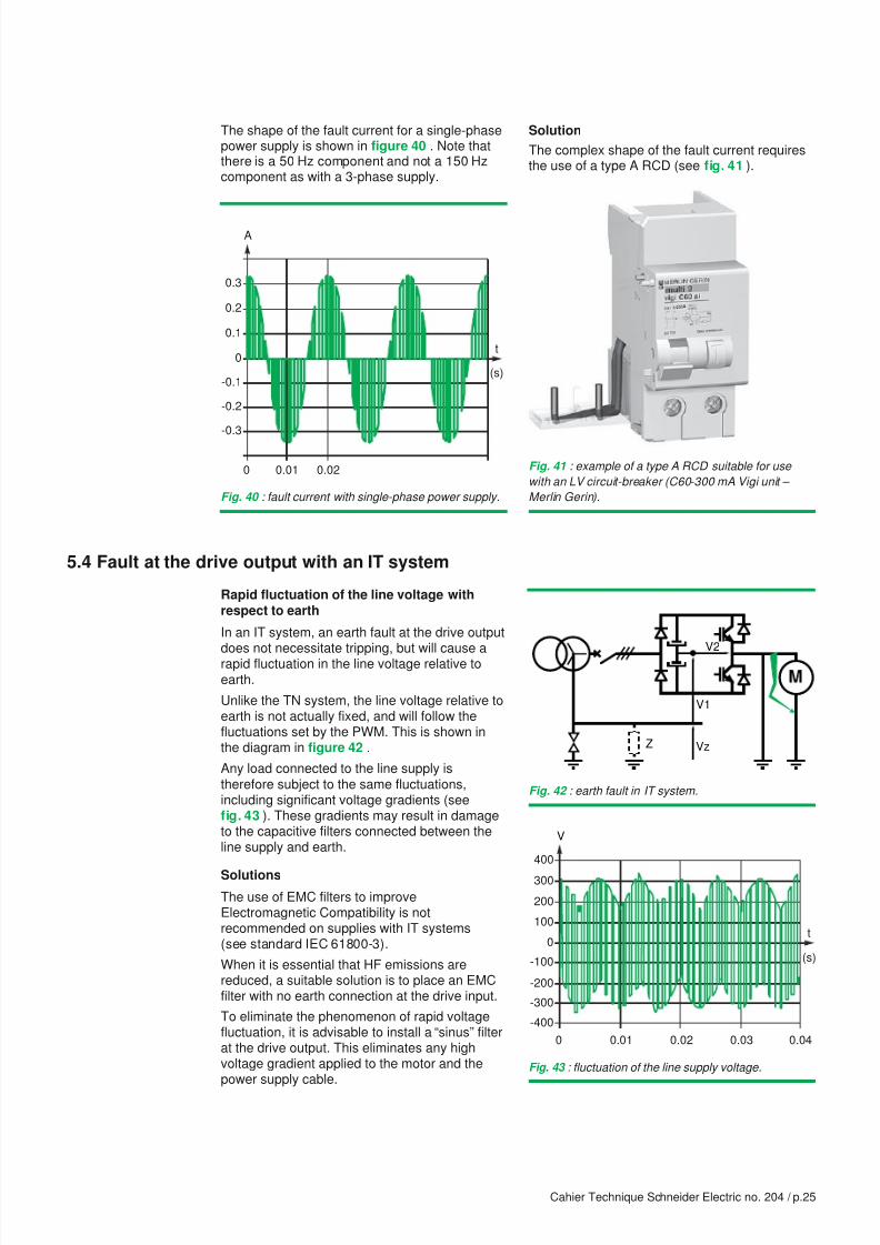
Fig. 40 : fault current with single-phase power supply.
The shape of the fault current for a single-phasepower supply is shown in figure 40 . Note thatthere is a 50 Hz component and not a 150 Hzcomponent as with a 3-phase supply.
Fig. 41 : example of a type A RCD suitable for use
with an LV circuit-breaker (C60-300 mA Vigi unit –
Merlin Gerin).
Solution
The complex shape of the fault current requiresthe use of a type A RCD (see fig. 41 ).
-0.3
-0.2
-0.1
0
0.1
0.2
0.3
0.010
A
t
(s)
0.02
5.4 Fault at the drive output with an IT system
Rapid fluctuation of the line voltage withrespect to earth
In an IT system, an earth fault at the drive output
does not necessitate tripping, but will cause arapid fluctuation in the line voltage relative toearth.
Unlike the TN system, the line voltage relative toearth is not actually fixed, and will follow thefluctuations set by the PWM. This is shown inthe diagram in figure 42 .
Any load connected to the line supply istherefore subject to the same fluctuations,including significant voltage gradients (seefig. 43 ). These gradients may result in damageto the capacitive filters connected between theline supply and earth.
Solutions
The use of EMC filters to improveElectromagnetic Compatibility is notrecommended on supplies with IT systems(see standard IEC 61800-3).
When it is essential that HF emissions arereduced, a suitable solution is to place an EMCfilter with no earth connection at the drive input.
To eliminate the phenomenon of rapid voltagefluctuation, it is advisable to install a “sinus” filterat the drive output. This eliminates any highvoltage gradient applied to the motor and thepower supply cable.
Fig. 42 : earth fault in IT system.
Fig. 43 : fluctuation of the line supply voltage.
V1
VzZ
V2
-400
-300
-200
-100
0
100
200
300
400
0.020.01 0.030 0.04
V
t
(s)
8/9/2019 Schneider 204
http://slidepdf.com/reader/full/schneider-204 28/34
Cahier Technique Schneider Electric no. 204 / p.26
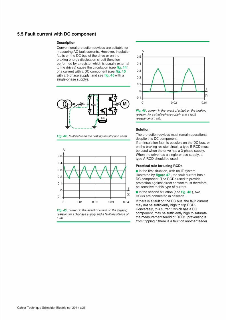
5.5 Fault current with DC component
Description
Conventional protection devices are suitable formeasuring AC fault currents. However, insulation
faults on the DC bus of the drive or on thebraking energy dissipation circuit (functionperformed by a resistor which is usually externalto the drives) cause the circulation (see fig. 44 )of a current with a DC component (see fig. 45with a 3-phase supply, and see fig. 46 with asingle-phase supply).
Fig. 44 : fault between the braking resistor and earth.
Fig. 45 : current in the event of a fault on the braking
resistor, for a 3-phase supply and a fault resistance of
1 k ) .
Fig. 46 : current in the event of a fault on the braking resistor, for a single-phase supply and a fault
resistance of 1 k ) .
Rb
-0.1
0
0.1
0.2
0.3
0.4
0.5
0.020 0.04
A
t
(s)
-0.1
0
0.1
0.2
0.3
0.4
0.5
0.020.01 0.030 0.04
A
t
(s)
Solution
The protection devices must remain operationaldespite this DC component.If an insulation fault is possible on the DC bus, oron the braking resistor circuit, a type B RCD mustbe used when the drive has a 3-phase supply.When the drive has a single-phase supply, atype A RCD should be used.
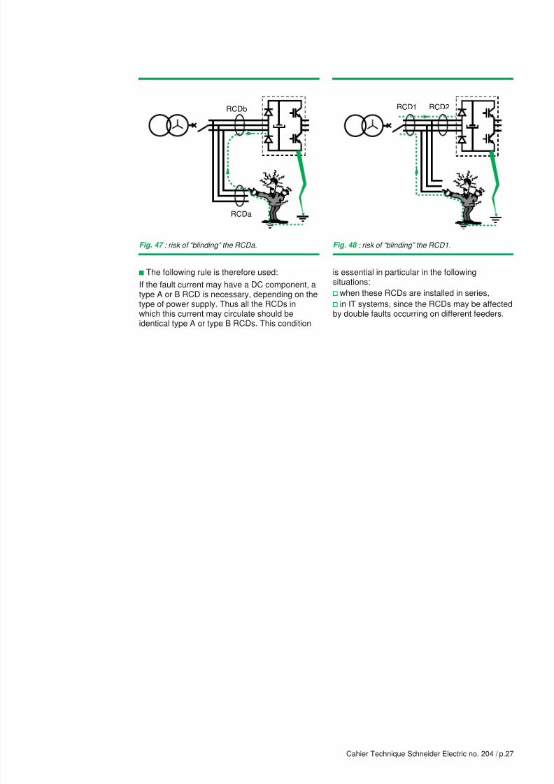
Practical rule for using RCDs
c In the first situation, with an IT system,illustrated by figure 47 , the fault current has aDC component. The RCDa used to provideprotection against direct contact must thereforebe sensitive to this type of current.
c In the second situation (see fig. 48 ), twoRCDs are connected in cascade.
If there is a fault on the DC bus, the fault currentmay not be sufficiently high to trip RCD2.Conversely, this current, which has a DCcomponent, may be sufficiently high to saturatethe measurement toroid of RCD1, preventing itfrom tripping if there is a fault on another feeder.
8/9/2019 Schneider 204
http://slidepdf.com/reader/full/schneider-204 29/34
Cahier Technique Schneider Electric no. 204 / p.27
Fig. 47 : risk of “blinding” the RCDa. Fig. 48 : risk of “blinding” the RCD1.
RCDa
RCDb
c The following rule is therefore used:If the fault current may have a DC component, atype A or B RCD is necessary, depending on thetype of power supply. Thus all the RCDs inwhich this current may circulate should beidentical type A or type B RCDs. This condition
RCD1 RCD2
is essential in particular in the followingsituations:
v when these RCDs are installed in series,
v in IT systems, since the RCDs may be affectedby double faults occurring on different feeders.

8/9/2019 Schneider 204
http://slidepdf.com/reader/full/schneider-204 30/34
Cahier Technique Schneider Electric no. 204 / p.28
6 Selection and installation recommendations
Based on the following principles:
c for the use of overcurrent protection devices(short-circuit and overload) covered in section 2,
c for the protection of persons, covered insection 3,
c then the special phenomena described in theprevious section,
this section gives practical recommendationsthat answer the question: how can I providecorrect protection for a circuit containing variablespeed drives?
Protection…
… against indirect contact … against direct contact
Power supply 3-phase Single-phase 3-phase Single-phase
Hardware and No double Double If an additional protection measure isinstallation insulation of insulation of necessary, in the event of failure ofcharacteristics the DC bus the DC bus other measures providing protection
against contact or carelessness ofusers (see installation standards)
Earthing system TT Type B, low Type A, low sensitivity Type A (30 mA) Type A (30 mA)(or IT with frames not sensitivity (u 300 mA) orconnected together) (u 300 mA) type B (30 mA) if
Earthing system TN-S Type A, low sensitivity (u 300 mA) [*]
Earthing system IT
[*] The insulation fault is similar to a short-circuit. Tripping must normally be performed by the short-circuitprotection device, but the use of an RCD is recommended if there is a risk of overcurrent protectiondevices not tripping.
6.1 Selection of RCDs (see fig. 49 )
Special recommendations:
c only connect one drive per RCD,c provide an RCD as an additional protection
Fig. 49 : type of RCD depending on the earthing system and the required protection.
6.2 Selection of PIMs
DC injection PIMs can be “misled” by a faultcausing a DC voltage between the line supplyand earth. Depending on the polarity of thisvoltage, the insulation level will be falselyincreased or decreased.
Only AC injection PIMs can therefore be used onsupplies without any electrical isolation used topower devices containing DC buses, such asvariable speed drives.
However, if there is a fault at a frequencyconverter output, the insulation measurementmay be distorted (see fig. 50 ). The converteractually behaves like a voltage source withvariable magnitude and frequency. This voltage
is added to the measurement voltage injected by
the PIM. If the frequency of this voltage is closeto the measurement frequency, the measurementis distorted.
PIM
Fig. 50 : disturbance of measurement of the PIM.
measure against direct contact when the brakingresistor is accessible.
the braking resistor
is accessible

8/9/2019 Schneider 204
http://slidepdf.com/reader/full/schneider-204 31/34
Cahier Technique Schneider Electric no. 204 / p.29
6.3 Prevention of malfunctions
The disturbance described in the precedingsections may cause undesired tripping of theprotection devices. For good continuity of service
it is recommended that the following instructionsare followed.
Precautions concerning RCDs
c Choose an appropriate model, which has:
v filtering of HF currents,
v a time delay (prevents any tripping due to thecharging current of the stray capacitance onpower-up). It is not possible to have a time delayfor 30 mA devices. In this case, choose devicesthat are immune to undesired tripping, forexample high-immunity RCDs in the s.i. range(Merlin Gerin brand).
c If possible raise the trip threshold, while
keeping to the limit values set for the protectionof persons.
These precautions are in addition to the rulesdescribed in section 5.5 on using RCDs.
Precautions concerning PIMs
Choose an appropriate model:
c AC injection type
or
c coded pulse type, which makes the driveoutput frequency irrelevant.
Precautions concerning installation
Converters must be used in accordance withstandards EN 50178 and IEC 61800-3.
Certain additional precautions may also benecessary.
c Reduce the capacitances to earth as much aspossible. To do this:
v avoid the use of shielded cables when theoperating environment permits,
v reduce the length of cable between the driveand the motor,
v ensure that the wiring is carried out in line withaccepted practice,
v avoid the use of EMC filters or use filters withlow capacitances (especially in IT systems).
c Reduce the PWM frequency (reduction of the
number of switching operations per second andtherefore reduction of the rms value of the HFcurrents).
c Divide the drives over a number of RCDs (toavoid bringing the leakage currents together).
c Place “sinus” filter at the drive output(elimination of voltage gradients applied to thecables).
c Use an isolation transformer and place theRCD upstream (separation of the circuit which isdisturbed by the drive from its power supply).

8/9/2019 Schneider 204
http://slidepdf.com/reader/full/schneider-204 32/34
Cahier Technique Schneider Electric no. 204 / p.30
Bibliography
“Products” standards
c IEC 60479: Guide to the effects of currentpassing through the human body.
c IEC 60755: General requirements for residualcurrent operated protective devices.
c IEC 60947-2: Low voltage switchgear - Part 2:Circuit-breakers.
c IEC 61008, EN 61008-1 et 61008-2: Residualcurrent operated circuit-breakers for householdand similar use.
c IEC 61009, EN 61009-1 et 61009-2: Residualcurrent operated circuit-breakers with integral
overcurrent protection for household andsimilar use.
c IEC 61800-3: Adjustable speed electricalpower drive systems - Part 3: EMC productstandard.
c EN 50178: Electronic equipment used in
power installations.
c UTE C 60-130: Dispositifs de protection àcourant différentiel résiduel.
c NF C 61-420: Petits disjoncteurs différentiels.
c NF C 62-411: Matériel de branchement etanalogues, disjoncteurs différentiels pourtableaux de contrôle des installations depremière catégorie.
“Installation” standards
c IEC 60364: Electrical installations of buildings.
Schneider Electric Cahiers Techniques
c Residual current devices in LV.R. CALVAS, Cahier Technique no. 114.
c Protection of people and uninterruptible powersupplies.J-N. FIORINA, Cahier Technique no. 129.
c Earthing systems in LV.B. LACROIX and R. CALVAS,Cahier Technique no. 172.
c Earthing systems worldwide and evolutions.B. LACROIX and R. CALVAS,Cahier Technique no. 173.
c Disturbances of electronic systems andearthing systems.R. CALVAS, Cahier Technique no. 177.
c The IT earthing system (unearthed neutral)in LV.F. JULLIEN and I. HERITIER,Cahier Technique no. 178.
c Cohabitation of high and low currents.R. CALVAS and J. DELABALLE,Cahier Technique no. 187.

8/9/2019 Schneider 204
http://slidepdf.com/reader/full/schneider-204 33/34

8/9/2019 Schneider 204
http://slidepdf.com/reader/full/schneider-204 34/34
eiderElectric