school of engineering and technology semester: i course
TRANSCRIPT

Pag
e1
School of Engineering and Technology
Department of Electrical Engg.
First Year M.Tech. Electrical Engineering (Power System)
Year: First Year Semester: I
Course: Computer Analyses In Power System Course Code:PEP101
Teaching
Scheme
(Hrs/Week)
Continuous Internal Assessment (CIA) End Semester
Examination Total
L T P C CIA-1 CIA-2 CIA-3 CIA-4 Lab Theory Lab
3 - 2 4 10 20 10 10 50 50 50 200
Max. Time, End Semester Exam (Theory) -3Hrs.
Prerequisite 1. Formulate and solve power flow problems
2. Power system analysis
Course Objectives
1 Course describes mainly computer modeling techniques that constitute the framework of modern
power system analysis.
2 Covered power system analysis, load or power flow, AC system faults and the electromechanical
behavior of power systems
3 Dynamic models of power system plants and their use in multi-machine transient stability analysis,
4 Harmonic flow analysis, power system security and optimization analysis.
Course Content
Unit
No.
Module
No. Content Hours
1 I
Optimization Techniques
Introduction, Statement of an optimization problem, design vector, design
constraints, constraint surface, objective function, classification of
optimization problem, Classical optimization Techniques, single variable
optimization, Direct substitution method, constrained variation method,
Lagrange Multiplier method, formulation of multivariable optimization,
Nonlinear Programming, Unconstrained optimization Techniques, Direct
search methods, Indirect search methods, Descent methods.
9
2 I
Load Flow Studies
Revision of Load flow studies by using Newton Raphson method (polar and
rectangular). Contingency evaluation, concept of security monitoring,
Techniques of contingency evaluation, Decoupled load flow and fast
decoupled load flow. Single phase and three phase load flow problem
notation, specified variables, derivationof equations.
9
3 I
DC load flow:
Introduction, formulation of problem, D.C. System model,
convertervariables, Derivation of equations, Inverter operation, generalized
flow chart for equation solution, ETAP case study on Automatic alert of
overloaded components & abnormal voltages; Automatic switching of
charger & UPS models based on load conditions; Automatic switching of DC
motor models based on terminal voltages.
9
4 I Optimal Power Flow Analysis
Optimal power flow analysis considering equality and inequality constraints.
Economic dispatch with and without limits (Classical method) Gradient
9

Pag
e2
method, Newton’s method, Newton Raphson method. Optimize power
exchange with other systems (on-site generation, utilities, IPP’s, & power
grids); Minimize load shedding; Maximize voltage & flow security indices.
5 I
Fault Analysis: Revision of symmetrical and unsymmetrical faults, formulating the
sequenceimpedance matrix, fault configurations and equations, General
computer simulation for fault analysis.
8
Total No. of Hrs 44
Beyond the Syllabus
1. Develop and select appropriate models corresponding to problem descriptions in the engineering
field and solve them correctly. 2. Develop algorithms as well as use software tools to solve practical optimization problems and to
conduct analysis
Course Outcome
Students should able to
CO1 Apply the methods of optimization in real life situation
CO2 Develop proper mathematical models for analysis of load flow study.
CO3 Select and identify the most appropriate algorithm for DC load–flow
CO4 Prepare the practical input data required for load flow or fault calculations.
CO5 Develop proper mathematical models for fault analysis.
List of Experiments (Expandable):
Sr.
No.
Description
Computer Applications In Power Systems (Minimum Three)
1 Load flow analysis by using Newton Raphson method on digital computer.
2 Optimal Power flow analysis.
3 AC-DC load flow analysis on digital computer.
4 Analysis of various types of faults on digital computer.
5 Short circuit analysis.
Resources
Recommended
Books
1.Computer Aided Power System Operation and Analysis-R.N.Dhar, Tata McGraw Hill
New Delhi.
2.Computer Techniques in Power System Analysis- M.A. Pai, Tata Mc-Graw Hill New
Delhi.
3. Computer Methods in Power System Analysis- Stagg and El.Abiad, Mc-Graw Hill (International Student Edition.)
Reference
Books
1.Computer Analysis of Power Systems-J.Arrilinga, C.P.Arnold. Wiely
Eastern Ltd.
2.Optimisation Techniques-S.S.Rao, Wiely Eastern Ltd, New Delhi.
3.Modern Power System Engineering, Nagrath and Kothari (Tata McGraw Hill )
4.Electrical Energy System Theory–an introduction- Olle Elgerd. TMH
Publishing Company, New Delhi.
5.Power System Optimisation- D. P. Kothari, J. S. Dhillon, PHI.
Power Generation Operation and Control – Allen Wood, Wiley Publications.
E-Resources https://onlinecourses.nptel.ac.in/explorer

Pag
e3
School of Engineering and Technology
Department of Electrical Engg.
First Year M.Tech. Electrical Engineering (Power System)
Year: First Year Semester: I
Course: FACTS Course Code:PEP102
Teaching
Scheme
(Hrs/Week)
Continuous Internal Assessment (CIA) End Semester
Examination Total
L T P C CIA-1 CIA-2 CIA-3 CIA-4 Lab Theory Lab
3 - 2 4 10 20 10 10 50 50 50 200
Max. Time, End Semester Exam (Theory) -3Hrs.
Prerequisite 1. Comprehend basic concepts and principles in power system analysis.
2. Power system generation and load dispatch
Course Objectives
1 To develop ability to analyse and use various methods to improve stability of the power systems.
2 To educate students for utilization of software such as PSCAD, MATLAB for power transmission
and control.
3 To analyse the performance of power systems with FACTS controllers.
4 Model FACTS controllers for load flow and dynamic analysis.
5 To analyse application of FACTS controller.
Course Content
Unit
No.
Module
No. Content Hours
1
I
Overview of compensation of transmission Line
Basic Issues Involved in Bulk Power Transmission, Review of basics of
power transmission networks-control of power flow in AC transmission line-
Analysis of uncompensated AC Transmission line- Passive reactive power
compensation, Principle of Transmission system compensation,
6
II Overview of FACTS Controller
Need for FACTS controllers, types of FACTS controllers and Benefits,
Application of FACTS Controller.
5
2 I
Shunt Compensation-Static VAR compensation and its Purpose
Operation and control of SVC, Influence of SVC on system voltage, Design
of SVC voltage regulator, Modeling of SVC for power flow and stability
studies, Applications- Enhancement of transient stability, Steady state power
transfer, Enhancement of Power system damping, Prevention of voltage
instability
8
3 I
Shunt Compensation –STATCOM
STATCOM configuration and control, Power flow control with STATCOM,
Modeling of STATCOM for power flow studies, applications of STATCOM
8
4 I
Series Compensation- Thyristor & GTO Thyristor Controlled Series
Capacitors (TCSC & GCSC)
Concepts of Controlled Series Compensation –Analysis of TCSC-GCSC ,
Different modes of operation, Modeling of TCSC and GCSC for load flow
studies- modeling TCSC and GCSC for stability studies- Applications of
TCSC and GCSC
5

Pag
e4
II
Static synchronous series compensator(SSSC)
Operation of SSSC, Power flow control with SSSC, Modeling of SSSC for
power flow studies, applications of SSSC
4
5
I
Unified Power Flow Controller
UPFC configuration, steady state operation control and characteristics,
introduction to transient performance, operational constraints of UPFC,
Power flow studies in UPFC embedded systems. Applications of Unified
power flow controller.
9
Total No. of Hrs 45
Beyond the Syllabus
Develop mathematical and circuit models of the FACTS devices and use them for series
compensation, shunt compensation, controlling the line power flow and enhancing transmission
capacity.
Course Outcome
Students should able to
CO1 Analyze the Operation of various Shunt and series devices and their control.
CO2 Identify configuration of FACTS controller required for a given application
CO3 Analyze the FACTS controller required for power flow.
CO4 Analyze the the FACTS controller required for stability analysis.
List of Experiments (Expandable):
Sr.
No
.
Description
FACTS ( Minimum Three)
1 To study simulation of Static Var Compensator (SVC)
2 Hardware / software Simulation of TCR.
3 Simulation of STATCOM.
4 Study of operation of Unified Power Flow Controller.
Resources
Recommended
Books
1. Power Electronic control in Electrical Systems – E.Acha, V.A.Agelidis,
O.Anaya-lara and TJE Miller , Newnes, Oxford.
2. Understanding FACTS- N.G. Hingorani and L.Gyugi, IEEE Press, New York.
Reference
Books
1. FACTS controllers in transmission and Distribution – K.R.Padiyar, New Age
Publications, New Delhi.
E-Resources https://onlinecourses.nptel.ac.in/explorer

Pag
e5
School of Engineering and Technology
Department of Electrical Engg.
First Year M.Tech. Electrical Engineering (Power System)
Year: First Year Semester: I
Course: Power System Modeling Course Code:PEP103
Teaching
Scheme
(Hrs/Week)
Continuous Internal Assessment (CIA) End Semester
Examination Total
L T P C CIA-1 CIA-2 CIA-3 CIA-4 Lab Theory Lab
3 - 2 4 10 20 10 10 50 50 50 200
Max. Time, End Semester Exam (Theory) -3Hrs.
Prerequisite 1. Analyze electromechanical devices and machines
2. Reference frame theory to study and analyze the behavior of synchronous machines.
Course Objectives
1 Introduce basic modeling concepts of various power system components.
2 Develop detail model of synchronous machine for dynamic studies.
3 Analyze synchronous machine model for steady state & transient state
4 Describe basics of excitation systems, voltage regulators and their parameters.
5 Develop models of different excitation systems
6. Extend concept of mathematical modeling for transmission line, SVC and loads
Course Content
Unit
No.
Module
No. Content Hours
1 I
Modeling of Power System Components
The need for modeling of power system, different models for power system
analysis. Simplified models of non-electrical components like boiler, steam,
hydro-turbine & governor system. Transformer modeling, tap-changing &
phase-shifting transformer modeling.
8
2 I
Synchronous machine modeling
Model for steady-state analysis. The development of model for dynamic
studies. The current & flux linkage models using Park’s transformation
leading to simulation as linear model.
9
3 I Analysis of synchronous machine modeling
Synchronous machine connected to an infinite bus, its simulation for steady-
state condition and transient conditions.
9
4 I
Excitation system modeling
Simplified view of excitation control, Excitation configuration, primitive
systems, Definitions of voltage response ratio & exciter voltage ratings,
Excitation control systems using dc generator exciter, alternator-rectifier,
alternator-SCR, voltage regulators such as electro-mechanical and solid state.
9
5 I
Transmission line, SVC and load modeling
Transmission line modeling; static VAR compensator modeling; load
modeling. (including induction motor modeling); Software simulation of any
one modeling.
9
Total No. of Hrs 44

Pag
e6
Beyond the Syllabus
Model the electrical machine from the terminal junction with transmission systems
Course Outcome
Students should able to
CO1 Implement principles of modelling and analysis of power systems subject to components of
Power Systems
CO2 Evaluate the mathematical formulation and use of symmetrical components
CO3 Model all the parameters of a synchronous machine
CO4 Analyze the model of synchronous machine and Excitation system
CO5 Apply the principles of modelling and for transmission line, SVC and load
List of Experiments (Expandable):
Sr.
No.
Description
Power System Modeling ( Minimum Three)
1 Steady state analysis of synchronous machine using SIMULINK as a linear model.
2 Steady state Analysis of synchronous machine connected to infinite bus using SIMULINK.
3 Steady state analysis of excitation control systems using SIMULINK.
4 Induction Motor Modeling.
Resources
Recommended
Books
1. Power Systems Dynamics – K.R.Padiyar, B.S. Publications. 2. Power System Control and Stability – Vol. – I – Anderson & Foud, IEEE Press,
New York.
Reference
Books
1. Power System Dynamics & Control – Kundur, IEEE Press , New York 2. Power System Operation & Control – P.S.R. Murthy
3. “Electrical Energy System Theory – an introduction” by Olle Elgerd. TMH
Publishing Company 2nd Edition, New Delhi
4. “Power System Analysis” – John J. Granier and W.D. Stevenson Jr, 4th Edition,
McGraw Hill International student edition
E-Resources NPTEL Web & Video , Course-Power system analysis

Pag
e7
School of Engineering and Technology
Department of Electrical Engg.
First Year M.Tech. Electrical Engineering (Power System)
Year: First Semester: I
Course: Research Methodology Course Code:17RDP101
Teaching
Scheme
(Hrs/Week) Continuous Internal Assessment (CIA)
End Semester
Examination Total
L T P C CIA-1 CIA-2 CIA-3 CIA-4 Lab Theory Lab
4 - - 4 10 20 10 10 - 50 - 100
Max. Time, End Semester Exam (Theory) -3Hrs. End Semester Exam (Lab) - NA
Course Objectives
1 Critically evaluate current research
2 Develop hypothesis and a research proposal
3 Illustrate method of communication of scientific results for peer review
Course Content
Unit
No.
Module
No. Content Hours
1
I
Introduction:Meaningandpurposeofresearch,objectivesofresearch,typesof Research, significance of research, research approaches, research methods
v/s methodology, research process, criteria of good research. Research and
scientific methods.
4
II
Research Problem: Steps in research: identification, selection and
formulation of research problem- research questions-research design-
formulation of hypothesis-review of literature .Definition, necessity and
techniques of defining research problem; formulation of research problem;
objectives of research problem.
5
2
I Research Design: Need and features of good research design. Types of research Designs, basic principles of experimental designs; design of experiments.
4
II
Data Collection: Primary and secondary data. Collection methods-
observation –Interview–questionnaire–schedule-pretest-pilotstudy-
experimentaland case studies, secondary data-relevance, limitations and
cautions
5
3
I
Sampling Design: Sampling theory-types of sampling-steps in sampling- Sampling and non-sampling error-sample size- advantages and limitations of
sampling. 4
II
Census and sample surveys, different types of sample designs,
characteristics of good sample design. Techniques of selecting a random
sample
5
4 I Parametric and non- parametric tests of hypothesis testing, non-parametric 4

Pag
e8
tests like sign, run, Kruskal –Wallistest and Mann-Whitney test. Testing of
significance of mean, proportion, variance and correlation-testing for
significance of difference between means, proportions, variances and
correlation coefficients. Limitations of tests of hypothesis, one-way and two-
way Anova-Latin square tests for association and goodness of fit.
II
HypothesisTesting:Fundamentalsandprocedureofhypothesistesting,flow Diagram for hypothesis testing. Measurement in research: measurements
cales- tests of good measurement construction of like r t and semantic
differential scales- source of errors in measurement-scale validation.
5
5
I
Technical Paper and Report Writing: Basic concepts of paper writing and report writing, review of literature, concepts of bibliography and references, Significance of report writing, steps of report writing, types of research reports, methods of presentation of report.
4
II
Structuring the Report: Types of reports, contents, styles of reporting, steps
in drafting reports, chapter format, pagination, identification, using
quotations, presenting footnotes-abbreviations, presentation of tables and
figures, referencing, documentation, use and format of appendices-
indexing editing and evaluating the final draft.
4
III
Research Ethics: Ethical issues, ethical principles that govern research,
ethically valid in formation sources, regulatory compliance. Introduction to
IPR and Patent registration.
2
Total No. of Hrs 46
Course Outcome
Students should able to
CO1 Student will be able to critically evaluate current research.
CO2 Student will be able to formulate research problem.
CO3 Student will be able to develop hypothesis and a research proposal
CO4 Student will be able to illustrate method of communication of scientific results for peer review
CO5 Student will be have a clear view of writing research paper and report.
RecommendedResources
Reference Books 1. Fisher R. A., Statistical Methods for Research Workers, Macmillan
Pub Co 1970.
2. Montgomery D. C., Design and Analysis of Experiments, John Wiley,
2001
3. Kothari C. R., Research Methodology: Methods and Techniques,
Second Edition, New Age International Publishing, 2004.
4. Panneerselvam R., Research Methodology, Prentice Hall Publication,
2004.
School of Engineering and Technology

Pag
e9
Department of Electrical Engg.
First Year M.Tech. Electrical Engineering (Power System)
Year: First Year Semester: I
Course: Power Electronics Converter (Elective-I) Course Code:PEPE01
Teaching
Scheme
(Hrs/Week)
Continuous Internal Assessment (CIA) End Semester
Examination Total
L T P C CIA-1 CIA-2 CIA-3 CIA-4 Lab Theory Lab
4 - - 4 10 20 10 10 - 50 - 100
Max. Time, End Semester Exam (Theory) -3Hrs.
Prerequisite
1. Understanding of characteristics of Power electronics elements such as SCRs, GTOs,
IGBTs and use them in practical systems. 2. Power Electronics
Course Objectives
1 To describe the role of Power semiconductor devices in power electronics.
2 To understand the operation of thyristors and their characteristics with commutation Techniques.
3 To learn the basic concepts of operation of DC choppers.
4 To analyze and synthesize pulse width modulated inverters, controlled rectifiers and AC voltage
controllers.
5 To learns the role of Power Electronics in utility related applications.
Course Content
Unit
No.
Module
No. Content Hours
1 I
Power SemiconductorDevices: Review of line commutated converters,
inverters, voltage control & Power factor improvement. Power Devices: BJT,
MOSFET, IGBT & GTOs - operating characteristics and gate drive
requirements and circuits.
9
2 I
Natural Commutation: forced Commutation; self-commutation; impulse
commutation; resonant pulse commutation and complementary commutation;
DC Choppers: DC- DC converters - principle of operation of buck, boost,
buck-boost, Cuk, flyback, forward, push-pull.
9
3 I
AC to DC Converters: 1-phase and 3-phase half controlled and fully
controlled bridge converters with RLE loads; freewheeling diodes; Dual
Converter; sequence control of converter-inverter operation; Effect of source
inductance on commutation; Harmonic analysis of source current.
9
4 I
Multi level converters: voltage source inverters:- single phase & six step
inverters, voltage control & PWM strategies, space vector modulation
Load commutated inverters: principle of operation, modification of power
circuit configuration for low frequency operation.
9
5 I Current source inverters: single phase and three phase power circuit
configuration and analysis. 9
Total No. of Hrs 45
Beyond the Syllabus
Design power circuit and protection circuit of PSDs and converters.

Pag
e10
Course Outcome
Students should able to
CO1 Distinguish between Power Semiconductor devices based on its characteristics
CO2 Apply the principals of DC chopper for DC-DC conversion
CO3 Design and analyze AC-DC Converters in Rectification and Inversion Mode
CO4 Apply the concept of PWM technique for Inverters
CO5 Design and analyze AC Voltage Regulators
Resources
Recommended
Books 1. M. H. Rashid, "Power Electronics Circuits, Devices and Applications ",
Prentice Hall India, Second Edition, New Delhi.
2. Ned Mohan, “Power Electronics: Converters, Design and Applications”,
Underland Robbins John Wiley and Sons, 2004.
1. B. K. Bose, “Modern Power Electronics and AC drives”, Pearson
Education Inc., 2002.
Reference
Books 1. M. D. Singh and Khanchandani, “Power Electronics”, Tata Mc-Graw Hill.
2. Vedam Subramanyam, Power Electronics”, Tata Mc-Graw Hill
1. Ned Mohan & Robin, “First course in Power Electronics” John Wiley &
Sons, Inc.
E-Resources https://onlinecourses.nptel.ac.in/explorer

Pag
e11
School of Engineering and Technology
Department of Electrical Engg.
First Year M.Tech. Electrical Engineering (Power System)
Year: First Year Semester: I
Course: High Voltage And Partial Discharge (Elective-I) Course Code: PEPE02
Teaching
Scheme
(Hrs/Week)
Continuous Internal Assessment (CIA) End Semester
Examination Total
L T P C CIA-1 CIA-2 CIA-3 CIA-4 Lab Theory Lab
4 - - 4 10 20 10 10 - 50 - 100
Max. Time, End Semester Exam (Theory) -3Hrs.
Prerequisite 1. Power system engineering
2. Electrical material science.
Course Objectives
1 Insulation system in electrical equipment is expected serve design life without any failure.
2 Prior to commissioning and during service life the electrical insulation is subjected to electrical
stresses.
3 Partial discharge (PD) is an electrical discharge or spark that bridges a small portion of the insulation
between two conducting electrodes. Improper electrical field management, manufacturing defects and
voltage surges beyond design scope leads to partial discharges inside electrical equipment causing
stress time dependent failure.
4 Detection of partial discharges and corrective actions are required to strengthen the manufacturing
processes, improve service life and avoid catastrophic failures of equipment.
5 Insulation system in electrical equipment is expected serve design life without any failure.
Course Content
Unit
No.
Module
No. Content Hours
1 I
The Phenomenon of Partial Discharge (PD ):
Definition of terms, typical electrode configurations with PD, internal
discharges and surface discharges, external discharges, equivalent circuits,
PD characteristics of parameters, wave-form and characteristics of an
individual PD pulse, train of PD current pulses, train of PD pulses in relation
to the temporarily assigned instantaneous value of the high voltage, non-
electrical PD characteristics parameters.
8
2 I
Fundamentals of PD Measuring Techniques:
On line and offline measurement methodologies. Wave form and spectrum of
PD, PD charge measuring equipment’s, integration in the frequency domain,
selectively wide band system, narrow band system, integration in the time
domain with very large wide band systems, measuring impedance or coupling
4 terminal device, PD measuring circuits, calibration, calibration pulses,
calibration of PD measuring setup, calibration of the complete test set up,
uncertainty of measurements. Different techniques of PD measurements-
acoustic method, UHF/VHF sensor/antenna methods, HFCT method.
9
3 I Screening and Filtering Problems during Partial Discharge
Measurements:
Need for screening, design of screens, completely enclosed screen, screen
9

Pag
e12
interruptions, effect of corners, cavity resonance, design of filters,
measurement of screening efficiency, lead through bushings.Challenges in on
site PD measurements.
4 I
Effects of PD on Electrical Insulating Materials:
Effects of PD and degradation mechanismin gaseous insulating materials,
liquid insulating materials, solid insulating materials and mixed
dielectrics.PD modeling in solid insulation materials.
9
5 I
Evaluation of PD:
Relation between measured and actual charge, relation between the time-
dependent occurrence of PD, and the extent of damage due to it, Need for PD
measurement, Development of PD measurement technique in cables,
problems during PD measurements on long cables, reflection and
superposition effects.PD measurement in power transformers and Gas
insulated switchgears using UHF PD measurements and Acoustic
Measurements. PD measurement in rotating machines –Coupling capacitor
technique.
9
Total No. of Hrs 44
Beyond the Syllabus
Designing power transmission lines operating at EHV/UHV voltages especially about insulation design,
corona losses, audible noise , insulation co-ordination.
Course Outcome
Students should able to
CO1 Understand the Phenomenon of Partial Discharge
CO2 Understand the methods to diagnose the partial discharge activity in a power equipment
CO3 Estimate electric field intensity of various electrode configurations for high voltage power
equipment CO4 Design a compact and economical insulation structure for high voltage equipment.
CO5 Evaluate the partial Discharge by various methods
Resources
Recommended
Books
1. Partial discharge detection in high-voltage equipment, F. H. Krueger,
Butterworth-Heinemann
2. Dieter Konig& Y Narayan Rao, PD in Electrical Apparatus. Vde-Veriaggmph –
Berlin.
2. High Voltage Engineering, O. Kuffel E, Zaengl W. S, Oxford, Pergamon.
Reference
Books
1. IEC 60270:2000 "High-Voltage Test Techniques – Partial Discharge
Measurements"
2. IEEE C57.124 1991(R2002) “IEEE recommended practice for the detection of
partial discharge and the measurement of apparent charge in dry-type
transformers”
3. IEC 60034-27:2007 "Rotating electrical machines – Off-line partial discharge
measurements on the stator winding insulation of rotating electrical machines"
4. IEEE 1434–2000 "IEEE Trial-Use Guide to the Measurement of Partial
Discharges in Rotating Machinery"
2. IEEE 400-2001 "IEEE Guide for Field Testing and Evaluation of the Insulation
of Shielded Power Cable Systems"
E-Resources https://onlinecourses.nptel.ac.in/explorer

Pag
e13
School of Engineering and Technology
Department of Electrical Engg.
First Year M.Tech. Electrical Engineering (Power System)
Year: First Year Semester: I
Course: Digital Signal Processing (Elective-I) Course Code:PEPE03
Teaching
Scheme
(Hrs/Week)
Continuous Internal Assessment (CIA) End Semester
Examination Total
L T P C CIA-1 CIA-2 CIA-3 CIA-4 Lab Theory Lab
4 - - 4 10 20 10 10 - 50 - 100
Max. Time, End Semester Exam (Theory) -3Hrs.
Prerequisite 1. Signals and systems
2. Mathematical tools for analysis of signals. Linear algebra, numerical computation
Course Objectives
1 To introduce discrete Fourier transform and its applications.
2 To teach the design of infinite and finite impulse response filters for filtering undesired signals.
3 To introduce signal processing in systems having more than one sampling frequency.
4 To introduce discrete Fourier transform and its applications.
Course Content
Unit
No.
Module
No. Content Hours
1 I
Discrete Signals and systems:
Sampling of continuous time signals, quantization, aliasing, Sampling
Theorem, Elementary discrete-time signals, classification, sequence
operations, Discrete-time systems and Classification, impulse response, linear
convolution and its properties, Z transform: basics, properties, inverse Z
transform using power series and partial fraction
8
2 I
Frequency response of discrete time systems:
Discrete-time systems described by difference equations, Analysis of LTI
discrete systems using z transform, frequency response of first order and
second order systems, transfer function, steady state and transient response,
phase and group delays, ideal filters and their pole zero locations, zero phase
and linear phase transfer functions.
7
3 I
Frequency analysis of discrete time signals:
Exponential representation of Fourier series and Fourier transform of
continuous time signals, The Fourier series for discrete-Time periodic signals
(only concept), The Fourier transform of discrete-time aperiodic signals (only
concept), Discrete Fourier Transform, Properties: periodicity, linearity, and
symmetry properties, Circular convolution, Linear convolution using circular
convolution, Fast Fourier Transform: Radix 2 DIT and DIF algorithms.
7
4 I
IIR and FIR Filters:
Advantages and disadvantages of digital filter over analog filters,
classification of digital filters: FIR and IIR, design of analog low pass
Butterworth filter, Chebyshev filter, Realization of IIR filters: direct form I,
direct form II, cascade and parallel, Comparison between FIR and IIR filters,
symmetric and antisymmetric FIR filters.
7

Pag
e14
5 I
Applications of DSP in Electrical Engineering: Measurement of power, measurement of frequency, Condition monitoring of
Electrical Machines, Power transformer protection, Synchronized phasor
measurement, Harmonic Analysis.
7
Total No. of Hrs 36
Beyond the Syllabus
To learn about DFT, its properties, applications and two different FFT algorithms
Course Outcome
Students should able to
CO1 Understand the signal processing fundamentals
CO2 Synthesize digital controllers for Frequency analysis
CO3 Analyze discrete time signals with the help of Mathematical transforms
CO4 Design the filters with the help of DSP
CO5 Apply the Digital Signal Processing Fundamentals for Electrical Engineering
Resources
Recommended
Books
1. Mitra S., “Digital Signal Processing: A Computer Based Approach”, Tata
McGraw-Hill, 1998, ISBN 0-07-044705-5
2. Proakis J., Manolakis D., “Digital signal processing”, 3rd Edition, Prentice
Hall, ISBN 81-203-0720-8
Reference
Books
1. Oppenheim A., Schafer R., Buck J., “Discrete time signal processing”, 2nd
Edition, Prentice Hall, 2003, ISBN-81-7808-244-6
2. Rebizant, Waldemar, Szafran, Janusz, Wiszniewski, Andrzej, “Digital Signal
Processing in Power System Protection and Control”, 1st Edition. Springer,
2011, ISBN 0857298011, 9780857298010
E-Resources https://onlinecourses.nptel.ac.in/explorer

Pag
e15
School of Engineering and Technology
Department of Electrical Engg.
First Year M.Tech. Electrical Engineering (Power System)
Year: First Year Semester: I
Course: VLSI DESIGN (Elective-I) Course Code:PEPE07
Teaching
Scheme
(Hrs/Week)
Continuous Internal Assessment (CIA) End Semester
Examination Total
L T P C CIA-1 CIA-
2
CIA-
3
CIA-
4 Lab Theory Lab
4 0 0 4 10 20 10 10 ----- 50 25 100
Max. Time, End Semester Exam (Theory) -3Hrs. End Semester Exam (Lab) – --Hrs.
Prerequisite 1. Basic knowledge of Wireless communication
2. Applications of wireless communication in mobile system.
Course Objectives
1. Provide an overview of VLSI design concept.
2. Understand the various types of logic circuits and design.
3. Different types arithmetic circuits and different methodologies used in VLSI.
4. Appreciate the contribution programmable concepts.
5. Understand the concepts of Verilog.
Course Content
Unit
No.
Module
No. Content Hours
1 I
Introduction:
Introduction to VLSI and VLSI fabrication- Introduction to power
reduction techniques-Dynamic Power Reduction-Static Power
Reduction- CMOS inverter– propagation delays – power dissipation -
Stick Diagram. MOS layers - design rules and layout- choice of layers.
9
2 I
VLSI Logic Circuits, Design Process and Layout:
Pass transistor and transmission gates inverter- NAND gates and NOR
Gates for n MOS, CMOS and Bi CMOS – parity generator –
multiplexers- code converters – PLA – Clocked sequential circuits-
Memories and Registers.
9
3 I
Arithmetic Circuits:
One bit adder- multi bit adder –Ripple carry-Carry Skip Adder-Carry
Look Ahead Adder- design of signed parallel adder-comparison of
different schemes in terms of delay - multipliers – Design of serial,
parallel and pipelined multipliers- different schemes and their
comparison. 2’s complement array multiplication-Booth encoding-
Wallace Tree multiplier.
9
Pag
e16
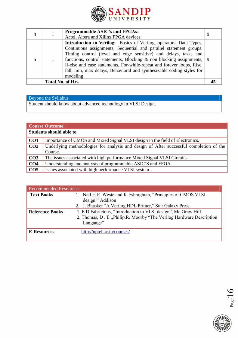
4 I Programmable ASIC’s and FPGAs:
Actel, Altera and Xilinx FPGA devices. 9
5 I
Introduction to Verilog: Basics of Verilog, operators, Data Types,
Continuous assignments, Sequential and parallel statement groups.
Timing control (level and edge sensitive) and delays, tasks and
functions, control statements, Blocking & non blocking assignments,
If-else and case statements, For-while-repeat and forever loops, Rise,
fall, min, max delays, Behavioral and synthesizable coding styles for
modeling
9
Total No. of Hrs 45
Beyond the Syllabus
Student should know about advanced technology in VLSI Design.
Course Outcome
Students should able to
CO1 Importance of CMOS and Mixed Signal VLSI design in the field of Electronics.
CO2 Underlying methodologies for analysis and design of After successful completion of the
Course.
CO3 The issues associated with high performance Mixed Signal VLSI Circuits.
CO4 Understanding and analysis of programmable ASIC’S and FPGA.
CO5 Issues associated with high performance VLSI system.
Recommended Resources
Text Books 1. Neil H.E. Weste and K.Eshraghian, “Principles of CMOS VLSI
design,” Addison
2. J. Bhasker “A Verilog HDL Primer,” Star Galaxy Press.
Reference Books 1. E.D.Fabricious, “Introduction to VLSI design”, Mc Graw Hill.
2. Thomas, D . E .,Philip.R. Moorby “The Verilog Hardware Description
Language”
E-Resources http://nptel.ac.in/courses/

Pag
e17
School of Engineering and Technology
Department of Electrical Engg.
First Year M.Tech. Electrical Engineering (Power System)
Year: First Year Semester: I
Course Advanced Switchgear and Relaying Course Code:PEP106
Teaching
Scheme
(Hrs/Week)
Continuous Internal Assessment (CIA) End Semester
Examination Total
L T P C CIA-1 CIA-2 CIA-3 CIA-4 Lab Theory Lab
3 - - 3 10 20 10 10 - 50 - 100
Max. Time, End Semester Exam (Theory) -3Hrs.
Prerequisite
1. Fundamentals of switchgear and power system protections
2. Basic protection scheme for power system components like transformer, generator &
transmission lines
Course Objectives
1 Introduce students to power system protection and switchgear.
2 Teach students the protection systems used for electric machines, transformers, bus bars, overhead
and underground feeders.
3 Develop in students an ability and skill to design the feasible protection systems needed for each
main part of a power system
4 Enhance students’ knowledge of over- voltage protection and data transmission.
5 To develop an ability and skill to design the feasible protection systems needed for each main part of
a power system in students.
Course Content
Unit
No.
Module
No. Content Hours
1 I
Introduction to Switchgear & Relaying- Contacts separation andarc phenomenon, theory of arc formation and its
extinction with Cassie arc model Mayr arc model, recovery voltage,
restriking voltage, interruption of capacitive and inductive currents, resistance
switching, double frequency transients, classification of circuit breakers,
Relay; types and application., Gas Insulated Switchgear.
9
2 I
Protection of series compensated transmission line
The Degree of compensation, basic components of series compensated
transmission lines, Voltage Profile of Series Compensated Line, Faults with
Unbypassed Series Capacitors, Protection problems such as Voltage
Inversion, Current Inversion, Overreaching/ Underreaching of distance
element.
9
3 I
Wide area measurement
Wide area measurement tools; monitoring and protection of system using
WAM, Challenges in WAM implementation in India , Architectures of wide-
area protection, concept of synchronized sampling, wide area phasor
measurement technology, concept of Adaptive relaying, advantageous of
adaptive relaying and its application. PMU
9
4 I Digital Relay
Comparison of digital relays with previous generation relays, Digital relays- 9

Pag
e18
Basic Components, Block diagram, Signal Conditioning Subsystems, Surge
Protection Circuits, Anti-aliasing filter, Conversion Subsystem, The
Sampling Theorem, Sample and Hold Circuit, A/D & D/A Conversion, Idea
of sliding window concept.
5 I
Numerical Relaying-
Numerical relaying algorithms for over current, distance and differential
protection with application to transmission system, transformer and bus bar
protection.
9
Total No. of Hrs 45
Beyond the Syllabus
Develop the advanced schemes for power system protection using new technologies such as synchronized
measurements, PMUs, GPS, fiber optics.
Course Outcome
Students should able to
CO1 Students are knowledgeable in the field of power system protection, and circuit breakers.
CO2 Students are knowledgeable in the field of relays.
CO3 Students will demonstrate and ability to design the relevant protection systems for the main
elements of a power system.
CO4 Students are knowledgeable in the field of over- voltage protection and the basics of data
transmission.
CO5 Numerical relaying & algorithms for power system component protection
Resources
Recommended
Books
1. Badriram and DN Vishwakarma, “Power System Protection and Switchgear”, TMH
2. Digital Protection: L.P.Singh 3. Sunil S. Rao, “Switchgear, Protection and Power Systems”, Khanna
Publishers
Reference
Books
1. A Chakrabarti, ML Soni, PV Gupta and US Bhatnagar, “Power System Engineering”
Dhanpat Rai & Sons.
2. IJ Nagrath and DP Kothari,”Power System Engineering” Tata McGraw-Hill.
3.CL Wadhwa, “Electric Power Systems”, Wiley Eastern Limited.
E-Resources https://onlinecourses.nptel.ac.in/explorer