school of materials and metallurgy, northeastern university, … · school of materials and...
TRANSCRIPT
Trans. Nonferrous Met. Soc. China 22(2012) 222−227
Recovery of carbon and cryolite from spent pot lining of aluminium reduction cells by chemical leaching
SHI Zhongning, LI Wei, HU Xianwei, REN Bijun, GAO Bingliang, WANG Zhaowen
School of Materials and Metallurgy, Northeastern University, Shenyang 110004, China
Received 29 November 2010; accepted 8 October 2011
Abstract: A twostep alkalineacidic leaching process was conducted to separate the cryolite from spent pot lining and to purify the carbon. The influencing factors of temperature, time, and the ratio of liquid to solid in alkaline and acidic leaching were investigated. The results show that the recovery of soluble compounds of Na3AlF6 and Al2O3 dissolving into the solution during the NaOH leaching is 65.0%,and the purity of carbon reaches 72.7%. During the next step of HCl leaching, the recovery of soluble compounds of CaF2 and NaAl11O17 dissolving into the HCl solution is 96.2%, and the carbon purity increases to 96.4%. By mixing the acidic leaching solution and the alkaline leaching solution, the cryolite precipitates under a suitable conditions of pH value 9 at 70 °C for 2 h. The cryolite precipitating rate is 95.6%, and the purity of Na3AlF6 obtained is 96.4%. Key words: spent pot lining; recovery; chemical leaching; aluminium electrolysis
1 Introduction
With a rapid development of the primary aluminium industry, more and more spent pot lining (SPL) is accumulated and needs to be dealt with. SPL is a hazardous solid waste from cell retrofitting. However, SPL contains some valuable inorganic compounds, such as Na3AlF6, NaF, CaF2, Al2O3 and NaAl11O17. The content of inorganic compounds in the SPL varies from 25% to 50% depending on the cell’s condition [1]. Besides the inorganic compounds, the other composition in the SPL is carbon that has graphitized at elevated temperature of 800−900 °C for several years. Graphitized carbon and inorganic compounds in SPL are valuable resources. In the past, the simplest way of dealing with SPL was the process of landfill which is not environmentally acceptable since the fluoride in SPL will penetrate and contaminate the underground water, and no valuable resources are recovered. Therefore, carbon and inorganic compounds may be recovered as a secondary resource.
Generally, there are some ways for treating SPL, including hydrometallurgical and pyrometallurgical processing, such as physical separation, thermal treatment and chemical leaching methods [2]. Physical
method separates the carbon and fluoride according to the difference in solubility, density and surface properties between carbon and fluorides. For example, the froth flotation technology is a typically physical separation process for SPL treatment [3]. However, physical separation method is difficult to improve the carbon purity and recovery efficiency of the leachable substance. For thermal treatment, the common way is to burn the SPL [4−7]. Although the SPL is decomposed, some waste in SPL transfers into the refractory components, and the fluoride is recovered as a gaseous HF effluent which can be absorbed with smelter grade Al2O3 [2], while the carbon is burnt for boiler heating. This thermal treatment is complicated in operation and the valuable source of carbon is not reused. In addition, the chemical leaching can leach the soluble compounds from the SPL by using NaOH or Al(NO3)3∙9H2O and AlCl3∙6H2O [8−10]. Because of the low reaction rate, the approach for treating Na3AlF6 and CaF2 using Al(NO3)3∙9H2O or AlCl3∙6H2O takes long time of 24 h at 25 o C [9, 10], which is not productive and very costly. However, the NaOH leaching just takes 2−3 h and the leaching reagent is economical.
In this work, three steps are conducted to separate the crolyite from the carbon in SPL. The first step of alkaline leaching is performed to dissolve Na3AlF6, NaF,
Foundation item: Project (50804010) supported by the National Natural Science Foundation of China Corresponding author: SHI Zhongning; Tel:+862483686464; Email: [email protected] DOI: 10.1016/S10036326(11)611643
SHI Zhongning, et al/Trans. Nonferrous Met. Soc. China 22(2012) 222−227 223
and Al2O3 into the basic solution. The second step of acidic leaching is carried out to further dissolve the CaF2 and NaAl11O17 in the carbon obtained from the first step into acidic solution. In the third step, the cryolite is precipitated by mixing the basic solution and acidic solution which come from the fore two steps.
2 Experimental
All used chemical reagents were analytical grade. Spent pot lining samples came from a 300 kA aluminium reduction cell. All the leaching experiments were run at a mechanical stirring system of 300 r/min at normal pressure. The concentration of NaOH leaching solution was 2.5 mol/L, while the concentration of HCl leaching solution was 9.7 mol/L. The experiment parameters of leaching and precipitation are shown in Table 1, where θ is the leaching temperature in alkaline leaching, acidic leaching and cryolite precipitating experiments, and t is the leaching time in alkaline leaching, acidic leaching and cryolite precipitate experiments, L/S is the liquid to solid ratio. The alkaline leaching solution after filtration was characterized by Raman spectroscopy (Horiba Jobin Yvon, HR800, France).
Table 1 Leaching and precipitating experimental parameters
Step θ/°C t/min (L/S)/ (cm 3 ∙g −1 ) pH
Alkaline leaching 60−100 20−240 2−6 Acidic leaching 60−100 20−240 2−6
Cryolite precipitate 20−100 20−1440 6−12
3 Results and discussion
3.1 Alkaline leaching The particle size of the SPL samples for alkaline
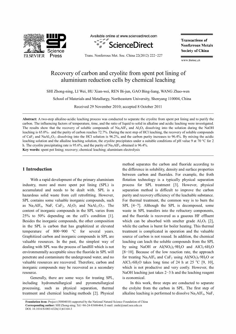
leaching is in the range of 100−165 µm after grinding. The element contents (mass fraction) of SPL are 13.91% Na, 13.83% F, 6.82% Al, 48.83% C, 1.19% Ca, and the balance of O and other trace elements measured by chemical analysis. The phase compositions of the SPL are Na3AlF6, NaF, CaF2, Al2O3, NaAl11O17, and carbon characterized by Xray diffraction (Panalytical B.V, PW 3040/60H, Netherlands), as shown in Fig. 1(a). The carbon in SPL has graphitized to 78.3% calculated by the Franklin Model [11]. 3.1.1 Effect of L/S ratio
SPL samples were leached in 2.5 mol/L NaOH solution for 2 h at 100 °C, and the L/S ratio varied in the range of 2−6 cm 3 /g. The results are shown in Table 2. It can be seen that the leaching rate of soluble compounds increases with increasing the L/S ratio in the range of 2−4.5. When the L/S goes up to 4.5, the increase of L/S ratio has no more effect on the carbon purity and the
Fig. 1 XRD patterns of SPL sample and leaching products
leaching rate. This is because increasing L/S ratio provides a mass of OH − to react with the soluble Na3AlF6 and Al2O3 in the L/S ratio range of 2−4.5. The concentration of soluble Na3AlF6 and Al2O3 in the leaching solution decreases with the increase of L/S ratio, which makes the leaching rate decrease when the L/S ratio further increases from 4.5 to 6. Therefore, the leaching rate does not increase when the L/S ratio is further increased from 4.5 to 6. Moreover, as seen in Table 2, the highest purity of carbon is 73.0%, and the highest leaching rate is 65.4%. This is not a desirable result for reusing the carbon, and so the second step is needed. After washing and filtering, the resulted solid carbon still contains insoluble compounds of CaF2 and NaAl11O17 characterized by XRD, as shown in Fig. 1(b).
Table 2 Effect of L/S ratio on alkaline leaching
(L/S)/ (cm 3 ∙g −1 ) Purity of carbon/% Leaching rate of
soluble compounds/%
6 73.0 65.4 5.5 72.9 65.2 5 72.9 65.2 4.5 73.0 65.0 4 68.8 57.7 3 64.9 49.4 2 55.9 26.1
3.1.2 Effect of temperature In the solution of 2.5 mol/L NaOH with a L/S ratio
of 5, the SPL was leached for 3 h at different temperatures of 60, 70, 80, 90 and 100 °C. The results are shown in Table 3. It is observed that the temperature has an appreciable effect on the leaching rate. The leaching rate increases from 36.8% to 65.0% when the temperature increases from 60 °C to 100 °C, while the carbon purity increases from 59.6% to 72.7%. This effect can be explained that the reaction velocity constant K increases with the increase of temperature.
SHI Zhongning, et al/Trans. Nonferrous Met. Soc. China 22(2012) 222−227 224
Table 3 Effect of temperature on alkaline leaching
Temperature/°C Purity of carbon/% Leaching rate of soluble compounds/%
60 59.6 36.8 70 61.9 42.6 80 67.1 54.2 90 69.2 58.4 100 72.7 65.0
3.1.3 Effect of reaction time The leaching tests were carried out at 100 °C in 2.5
mol/L NaOH solution, and the L/S ratio was 5 cm 3 /g. The reaction time was 20, 40, 60, 120, 180 and 240 min respectively. The results are shown in Table 4.
Table 4 Effect of reaction time on alkaline leaching
Time/min Purity of carbon/% Leaching rate of soluble compounds/%
20 56.2 27.1 40 56.0 27.1 60 58.9 34.8 120 67.1 54.2 180 72.7 65.0 240 73.0 65.4
The results indicate that the reaction time affects the dissolution of fluoride and oxide significantly. When the reaction time increases from 20 min to 240 min, the leaching rate rises from 27.1% to 65.4%, while the carbon purity increases from 56.2% to 73.0%. The leaching rate of 72.7% after leaching for 180 min is more economical and optimal. Therefore, the reaction time of 180 min is chosen for NaOH leaching. 3.1.4 Structure of solution after alkaline leaching
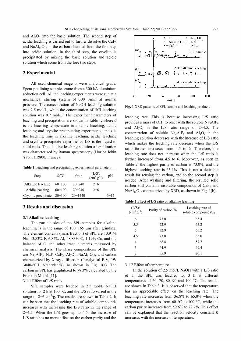
The Raman spectra of three solutions are shown in Fig. 2, in which one solution is obtained from alkaline
Fig. 2 Raman spectra of sodium aluminate: (a) Liquor after reaction of NaOH and SPL; (b) Liquor after reaction of NaOH and Na3AlF6; (c) Solution of sodium aluminate
leaching, one solution is the product of reaction between NaOH and Na3AlF6, and the other is sodium aluminate solution.
It can be seen from Fig. 2 that there are same peaks in spectra (a), (b) and (c) at about 625 cm −1 which are assigned to Al(OH)4 − ion [12−14]. However, the intensity of spectrum (a) is lower than that of spectra (b) and (c). It can be explained that the presence of more ions in the leaching solution diminishes the Al(OH)4 − peak intensity significantly. Moreover, there are two other peaks at about 427 cm −1 and 470 cm −1 in spectra (a) and (b) in Fig. 2, which are the characteristic peaks of Al2(OH)10 4−
and Al(OH)6 3− ions, respectively [15, 16]. The increase of Al(OH)4 − and OH − concentration makes Al(OH)6 3−
increase. The peak at 427 cm −1 is attributed to the forming of polymeric anions of Al2(OH)10 4− . Besides reactions (1) and (2), Al(OH)6 3− and Al2(OH)10 4− ions could be formed by reactions (3) and (4) according to Ref. [17−22]:
Na3AlF6+4NaOH=NaAl(OH)4+6NaF (1)
Al2O3+ 2NaOH+3H2O=2NaAl(OH)4 (2)
Al(OH)4 − +2OH − =Al(OH)6 3− (3)
2Al(OH)4 − +2OH − =Al2(OH)10 4− (4)
3.2 Acidic leaching As seen from Fig. 1(b), the obtained solid carbon
contains NaAl11O17 and CaF2 after NaOH leaching. For further purifying solid carbon and recovering fluorides, HCl leaching was carried out to separate carbon from NaAl11O17 and CaF2. In the HCl leaching process, NaAl11O17 is converted to soluble AlCl3 and NaCl, while a part of CaF2 is converted to CaCl2 and HF by reactions (5) and (6).
NaAl11O17+34HCl=NaCl+11AlCl3+17H2O (5)
CaF2+2HCl=CaCl2+2HF↑ (6)
The solid carbon and acidic leaching solution were obtained after filtering. And the acidic leaching solution was kept to precipitate Na3AlF6. 3.2.1 Effect of L/S ratio
The carbon obtained from the alkaline leaching was further leached in the acidic solution of 9.7mol/L HCl at 100 °C for 3 h. The L/S ratio varied in the range of 2−6. The result of acidic leaching is shown in Fig. 3.
From Fig. 3, it can be observed that the leaching rate increases from 83.2% to 96.2% when the L/S ratio increases from 2 cm 3 /g to 4 cm 3 /g. After that, the leaching rate keeps at a stable value of about 96%. This indicates that the optimal L/S ratio is 4 cm 3 /g.
The XRD analysis of carbon after twostep leaching is shown in Fig. 1(c). The impurities in this carbon were determined by chemical analysis, and the results are

SHI Zhongning, et al/Trans. Nonferrous Met. Soc. China 22(2012) 222−227 225
shown in Table 5. The content of impurity elements is reduced to a very low level, and the purity of carbon reaches a very high level of 96.4%.
Fig. 3 Influence of L/S on acidic leaching rate
Table 5 Impurities in carbon after twostep leaching (mass fraction, %)
Na F Al Ca Mg 0.73 0.21 0.27 0.07 0.06
3.2.2 Effect of reaction temperature In this tests, the carbon obtained from alkaline
leaching was leached in the solution of 9.7 mol/L HCl for 3 h, and the L/S ratio was 6. The temperature was varied in the range of 60−100 °C. The results of acidic leaching are shown in Fig. 4.
From Fig. 4, it is concluded that increasing temperature can increase the leaching recovery in the temperature range of 60−90 °C; however, the leaching rate almost does not change when the temperature increases from 90 °C to 100 °C. So, the acidic leaching temperature of 90 °C was chosen. 3.2.3 Reaction time
The tests were carried out in the solution of 9.7 mol/L HCl at 100 °C, and the L/S ratio was 6. The reaction time was 20, 40, 60, 120, 180 and 240 min,
Fig. 4 Influence of reaction temperature on acidic leaching
respectively. The result of acidic leaching is shown in Fig. 5.
The results indicate that the leaching rate reaches about 97% after leaching for 180 min, and it does not increase further when the leaching time prolongs to 240 min. So, the reaction time of 180 min was chosen for acidic leaching process.
Fig. 5 Influence of reaction time on acidic leaching
3.3 Precipitation of Na3AlF6 In the sodium aluminate solution, when the pH
value is less than 8, Al(OH)3 will precipitate. Therefore, it should be avoided during the precipitation of Na3AlF6. At high pH value, the aluminium ions are presented as Al(OH)4 − or [Al8(OH)26] 2− .
When the solution containing H + ion obtained from acidic leaching solution is added into the alkaline leaching solution which is concentrated with Na + cation, F − anion and its complex anion (AlFx 3−x ), sodium aluminate will react with hydrofluoric acid according to reaction (7) at a suitable pH value:
Al(OH)4 − +4H + +3Na + +6F − =Na3AlF6↓+4H2O (7)
The experiments were performed to obtain the optimal condition for the precipitation of Na3AlF6. The results in Fig. 6 show that the highest precipitating rate
Fig. 6 Precipitating rate of Na3AlF6 vs pH value and temperature

SHI Zhongning, et al/Trans. Nonferrous Met. Soc. China 22(2012) 222−227 226
of Na3AlF6 occurs at the pH value of 9 after reacting at 70 °C for 24 h.
The relationship of the precipitating rate of Na3AlF6 with the precipitation time is shown in Fig. 7. It is observed that the optimal precipitating time is 2 h, which is an economical time for precipitating Na3AlF6 (precipitating rate 95.6%). After filtration, the Na3AlF6 solid was confirmed by XRD analysis as shown in Fig. 8. The purity of Na3AlF6 is 97.0% according to chemical analysis.
Fig. 7 Effect of time on Na3AlF6 precipitation
Fig. 8 XRD pattern of precipitation solid substance
4 Conclusions
1) When SPL containing Na3AlF6 was dissolved in excessive sodium hydroxide, Al(OH)4 − was present.
2) In the first step of alkaline leaching, the purity of carbon reached 72.7%, while the leaching rate was 65.0%.
3) In the second step of acidic leaching, NaAl11O17
and CaF2 were dissolved into the solution. The purity of carbon was improved to 96.4% and the leaching rate was 96.2%;
4) Cryolite was precipitated from sodium aluminate liquor at the suitable pH value of 9 at 70 °C, the
precipitating rate is 95.6%, and the purity of Na3AlF6 obtained is 96.4%.
Acknowledgements The authors particularly appreciate Dr. Rudolf
KELLER for his help to improve this paper.
References
[1] PONG T K, ADRIEN R J , BESIDA J, O’DONNELL T A, WOOD D G. Spent pot lining: A hazardous waste made safe [J]. Transactions of the Institution of Chemical Engineers, 2000, 78(5): 204−208.
[2] YOUNG C A, NORDWICK S, FOOTE M. Review of technologies and the development of a novel approach for spent potlining remediation [C]//The Forth International Conference on Materials Engineering for Resources. Akita, Japan, 2001: 13−25.
[3] ZHAI X J, QIU Z X. Applying flotation to separate electrolyte from spent carbon cathode of aluminum electrolysis [J]. Nonferrous Metals, 1993, 45: 38−42. (in Chinese)
[4] PERSONNET P, MAURIENNE S J, BOUZAT G. Process for insolubilizing and consolidating spent linings from HallHeroult electrolysis cells: USA, 5947888 [P]. 1999.
[5] MANSFIELD K, SWAYN G, HARPLEY J. SPL treatment and fluoride recycling project [C]//TAYLLOR P R. Fundamentals of Advanced Materials for Energy Conversion. Seatlle, USA, 2002: 315−327.
[6] GOMES V, DRUMOUND P Z, NETO J O P, LIRA A R. Coprocessing at cement plant of spent potlining from the aluminum industry [C]//KVANDE H. Light Metals 2005. Warrendale, Pennsylnania: TMS, 2005: 507−513.
[7] LI W X, CHEN X P. Development of detoxifying process for spent potliner in CHALCO [C]//KVANDE H. Light Metals 2005. Warrendale, Pennsylnania: TMS, 2005: 515−517.
[8] FEMANDEZ L D, STEEL K M. Treatment of spent potlining for recovery of fluoride values [C]//SORLIE M. Light Metals 2007. Warrendale, Pennsylnania: TMS, 2007: 843−848.
[9] GROLMAN R J, HOLYWELL G C, KIMMERLE F M. Recycling of spent pot linings: USA, 5470559 [P]. 1995.
[10] SANJUAN B, MICHARD G. Aluminum hydroxide solubility in aqueous solutions containing fluoride ions at 50 °C [J]. Geochimica et Cosmochimica Acta, 1987, 51: 1823−1831.
[11] FRANKLIN R E. The structure of digital carbons [J]. Acta Crystallographica Section B: Structural Science, 1951, 4: 253−261.
[12] MOOLENAAR R J, EVANS J C, MCKEEVER L D. The structure of the aluminate ion in solutions at high pH [J]. Journal of Physical Chemistry, 1970, 74: 3629−3636.
[13] CHEN N Y, LIU M X, YANG J X, CHI L K. Influence of preparative history on structure and properties of sodium aluminate solutions [J]. Transactions of Nonferrous Metals Society of China, 1992, 2(2): 28−31.
[14] SIPOS P. The structure of Al(III) in strongly alkaline aluminate solutions—A review [J]. Journal of Molecular Liquids, 2009, 146: 1−14.
[15] LIU M X, CAO Y L, ChEN N Y, ZHUANG Z C. Raman spectra of sodium aluminate solutions with highcaustic ratio and high concentration [J]. Acta Metallurgica Sinica, 1992, 5(3): 224−226.
[16] MA S H, ZHENG S L, XU H B, ZHANG Y. Spectra of sodium aluminate solutions [J]. Transactions of Nonferrous Metals Society of China, 2007, 17(4): 853−857.
[17] FEMANDEZ L D, STEEL K M. Recovery of fluoride values from spent potlining: Precipitation of an aluminium hydroxyfluoride hydrate product [J]. Separation and Purification Technology, 2007,
SHI Zhongning, et al/Trans. Nonferrous Met. Soc. China 22(2012) 222−227 227 61: 182−192.
[18] NORDSTROM K, MAY H M. Aqueous equilibrium data for mononuclear aluminum species [M]//SPOSITO G. The Environmental Chemistry of Aluminum. Boca Raton, Florida: Lewis Publishers, 1996: 39−80.
[19] WU Y S, ZHANG D, LI M C, BI S W, YANG Y H. Periodical attenuation of Al(OH)3 particles from seed precipitation in seeded sodium aluminate solution [J]. Transactions of Nonferrous Metals Society of China, 2010, 20(3): 528−532.
[20] SCHOLZ G, KROSSNER M, DUMMER A. Structures, stabilities and vibrational frequencies of (AlF3)m(H2O)n adducts: A density functional study [J]. Journal of Molecular Structure: Theochem, 2000, 505: 117−132.
[21] XU Q, MA Y M, QIU Z X. Calculation of thermodynamic properties of LiFAlF3, NaFAlF3 and KFAlF3 [J]. CALPHADComputer Coupling of Phase Diagrams and Thermochemistry, 2001, 25:31−42.
[22] MARTIN R B. Ternary complexes of Al 3+ and F with a third ligand [J]. Coordination Chemistry Reviews, 1996, 149: 23−32.
化学法浸出废旧铝电解槽内衬回收冰晶石和碳粉
石忠宁,李 伟,胡宪伟,任必军,高炳亮,王兆文
东北大学 材料与冶金学院,沈阳 110004
摘 要:采用两步浸出法对铝电解槽废旧阴极炭块进行处理,以分离出冰晶石并提纯炭粉。研究不同温度、浸出
时间和液固比对浸出率的影响。结果表明,在 NaOH 浸出阶段,可溶性化合物 Na3AlF6 和 Al2O3 溶解于 NaOH溶
液中, 浸出率达到 65.0%, 所得炭粉纯度为 72.7%; 第二步采用HCl浸出得到炭粉, 可溶性化合物 CaF2 和 NaAl11O17
溶解到盐酸溶液中,浸出率达到 96.2%,炭粉纯度达到 96.4%。将上述碱浸和酸浸得到的浸出液进行混合以析出
冰晶石,在 pH=9、温度为 70 °C下沉积 2 h,其析出率达到 95.6%,所得冰晶石纯度为 96.4%。
关键词:废旧内衬;回收;化学浸出;铝电解 (Edited by YUAN Saiqian)