schreibman_ankletrauma_arrs_08
TRANSCRIPT

7/27/2019 Schreibman_AnkleTrauma_ARRS_08
http://slidepdf.com/reader/full/schreibmanankletraumaarrs08 1/10
State-of-the-Art Emergency and Trauma Radiology 1
Keywords: ankle joint, CT, juvenile Tillaux fracture,pilon fracture, radiography, triplane fracture, Weberfracture
1Department of Radiology, University of WisconsinMedical School, 600 Highland Ave., E3/311,Madison, WI 53792-3252. Address correspondenceto K. L. Schreibman ([email protected]).
CAT_07_3171
This chapter reviews the anatomy of the ankle joint and illustrates the com-
mon ankle injuries imaged emergently using radiography and CT, including the
following fractures: Weber, pilon, juvenile Tillaux, and triplane.
This chapter accompanies my lecture on ankle trauma presented as part of
the Categorical Course Syllabus titled State-of-the-Art Emergency and TraumaRadiology at the 108th annual meeting of the ARRS held in Washington, DC,on April 17, 2008. For a more complete discussion of CT and MRI of the ankleand foot, I suggest you read my chapter in Computed Tomography and Magnet-
ic Resonance Imaging of the Whole Body [1], a two-volume set edited by JohnR. Haaga and colleagues. You can download that chapter, and my other lecturematerials on musculoskeletal imaging and about PowerPoint (Microsoft), at myWebsite, www.schreibman.info.
AnatomyThe ankle joint is the articulation between the dome of the talus and the distal
tibia and fibula (Fig. 1A). “Ankle joint” is the preferred name of this joint inthe radiology and orthopedic surgery literature, rather than “tibiotalar joint” or
“crural joint.” The flat talar dome articulates with the flat surface at the distalend of the tibia known as the plafond (Fig. 1B). “Plafond” is an architecturalterm, meaning “a ceiling formed by the underside of a floor.” In essence, theplafond is the ceiling of the ankle joint that is formed by the floor of the tibia.The ankle joint is bounded on the sides by the inner articular surfaces of themedial and lateral malleoli. The plafond together with the malleoli form a rect-angular opening called the mortise into which the talar dome fits, analogous toa mortise-and-tenon joint in woodworking. The ankle mortise is a remarkablysturdy joint. Like the hip and knee joints, the ankle joint must bear our entirebody weight with every step. However, although it is common for primary os-teoarthritis to affect the hips and knees of many of us as we age, it is uncommonto be afflicted with primary osteoarthritis of the ankle.
The joint between the distal tibia and fibula is called the syndesmosis. “Syn-desmosis” is a Greek term meaning “to bind together,” and in general a syndes-motic joint is held together by thick connective ligaments. Most other joints inthe body, including the ankle and subtalar joints, are synovial joints in that theyare enclosed by a synovium-lined capsule that creates synovial fluid. The distalfibula, just above the lateral malleolus, fits into a shallow groove in the adjacenttibia, and this relationship is best visualized in the axial plane of a CT scan.
Imaging Ankle Trauma in the Emergency DepartmentAll ankle imaging examinations should begin with radiographs; for common
twisting injuries, such as the Weber fractures I discuss later in this chapter, rou-
Ankle TraumaKen L. Schreibman1

7/27/2019 Schreibman_AnkleTrauma_ARRS_08
http://slidepdf.com/reader/full/schreibmanankletraumaarrs08 2/10
2 2008 ARRS Categorical Course
Schreibman
CAT_07_3171
tine radiographs are usually sufficient. Intraarticular fracturesthrough the tibial plafond often require surgical open reduc-tion and internal fixation (ORIF) to restore the anatomic align-ment of the articular surfaces, and multiplanar reformatted CTscans are instrumental in surgical planning. I will discuss thethree distal tibial fractures that typically come to CT: the pilonfracture in adults and the juvenile Tillaux and triplane frac-tures in adolescents.
CT
At the University of Wisconsin in Madison, my colleaguesand I have developed our “F/A/T” CT protocol—that is, asingle scanning protocol that allows us to create multiplanarreformatted images optimized to visualize the foot, ankle, anddistal tibia (F/A/T). A discussion of our CT techniques is be-yond the scope of this chapter, but the latest versions of all ofthe musculoskeletal protocol sheets for the University of Wis-
A
Fig. 1—Gross anatomy of ankle joint. Ti =distal tibia, Fi = fibula.A, Ankle joint is articulation between domeof talus (Ta) and distal tibia and fibula. Jointbetween distal tibia and fibula is calledsyndesmosis (bracket ).B, Plafond (dotted line) is transverse cortical
articular surface at distal end of tibia. Mortiseis rectangular opening consisting of plafondas well as inner cortical articular surfaces(solid lines) of medial malleolus (MM) andlateral malleolus (LM). Talar dome fits intoankle mortise like mortise-and-tenon joint inwoodworking.
B
A C
Fig. 2—Non-weight-bearing radiographic ankle series in 37-year-old man with lateral ankle pain after acute inversion injury.A and B, Anteroposterior (A) and mortise (B) views show normal appearance of ankle joint.C, Lateral ankle view reveals no abnormalities of hind foot. Region outlined by dashed rectangle is magnified and displayed to right. Close inspectionof base of fifth metatarsal on lateral view of ankle reveals proximal diaphyseal fracture, so-called “Jones fracture” ( arrow ). Fractures of base of fifthmetatarsal often present clinically as lateral ankle pain. Technologists must be careful to include base of fifth metatarsal on at least one view of all ankleradiographic series.
B

7/27/2019 Schreibman_AnkleTrauma_ARRS_08
http://slidepdf.com/reader/full/schreibmanankletraumaarrs08 3/10
State-of-the-Art Emergency and Trauma Radiology 3
Ankle Trauma
CAT_07_3171
consin can be viewed and downloaded free of charge at www.Radiology.Wisc.Edu/MSKprotocols.
Radiography
Ankle radiographs can be obtained with the patient either
weight-bearing or non-weight-bearing, depending on the pref-erence of the ordering clinician. A standard radiographic an-kle series consists of three projectional views: anteroposterior(AP), mortise, and lateral (Fig. 2). The mortise view is similarto the AP view, but the leg internally is rotated 15° to betterprofile the ankle mortise.
When obtaining radiographs of the ankle, the technologistshould include the base of the fifth metatarsal on at least oneview. Fractures of the base of the fifth metatarsal clinicallypresent with the patient complaining of lateral ankle pain, andthis presentation can cause the clinician to request radiographsof the ankle rather than of the foot. Figure 2C is such a case inwhich the Jones fracture (Appendix 1) can be seen at the edge
of the lateral view.
Classification Schemes
Over the centuries, many classification schemes have beendevised to describe malleolar fractures and their relationshipto the ankle ligaments. As early as 1768, Sir Percivall Pott,in his article “Some Few General Remarks on Fractures andDislocations” [2], described a fracture of the fibula 2–3 inches(5–8 cm) above the tip associated with a tear of the deltoidligament and lateral subluxation of the talus [3]. The term“Pott’s fracture” has been applied to bimalleolar fractures, butthis term is a misnomer because the fracture Pott describedinvolved neither malleolus (Appendix 2).
In the 19th century, most of the writings about ankle injuriesoriginated from authors in France. In 1816, Dupuytren (Ap-
pendix 3) experimented with cadavers to produce ankle frac-tures [4, 5]. Subsequent French authors classified Dupuytren’sfractures as low if the fibular fracture was at the level of thesyndesmotic ligaments or as high if the fracture was at the
junction of the middle and distal thirds of the fibula accompa-
nied by disruption of the syndesmosis.The most meticulous and comprehensive classification ofankle injuries was developed by the prominent Danish sur-geon Niel Lauge-Hansen (1899–1976). Between 1948 and1956, he published a series of five articles describing five basicmechanisms of ankle injury [6–10]. The Lauge-Hansen clas-sification scheme uses two-word descriptors. The first worddescribes the initial position of the foot at the time of injury:in either supination or pronation. The second word describesthe injuring force acting through the talus: adduction, abduc-tion, eversion, or dorsiflexion. Thus, Lauge-Hansen classifiedankle fractures as follows: supination-adduction, supination-eversion, pronation-eversion, pronation-abduction, and prona-
tion-dorsiflexion; each of these five main types were furtherclassified into two to four substages. Lauge-Hansen thoughtthat it was important to understand the exact mechanism ofankle injuries because he believed that closed reduction of theankle fractures should be based on a reversal of the injuringforces in exact inverse order to that in which they occurred.This philosophy has not stood the test of time and, for most ofus, the Lauge-Hansen system is not used to communicate ourradiographic findings to orthopedic surgeons.
A more practical system for classifying ankle fractures wasfirst introduced by Robert Danis in 1949 [11], and it was mod-ified by Bernhard Georg “Hardy” Weber in 1972 [12]. TheDanis-Weber classification is based on the premise that thehigher the fibular fracture, the greater the syndesmotic injury,likelihood of displacement, and need for ORIF.
Fig. 3—Two models of ankle mortise.Skeleton on left shows relationship of talusto malleoli and syndesmosis. On right is sameanatomy using simple shapes. Intraosseousmembrane (IOM) is shown in yellow.Syndesmotic ligaments and anterior andposterior tibiofibular ligaments (Tib-Fig Lig)are modeled in green. Anterior and posteriortalofibular ligaments (Talo-Fib Lig) aremodeled in purple. Deltoid ligament (Delt Lig)is shown in blue. MM = medial malleolus,LM = lateral malleolus.
7/27/2019 Schreibman_AnkleTrauma_ARRS_08
http://slidepdf.com/reader/full/schreibmanankletraumaarrs08 4/10
4 2008 ARRS Categorical Course
Schreibman
CAT_07_3171
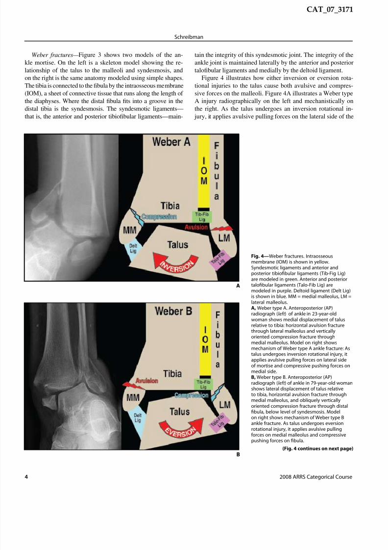
Weber fractures— Figure 3 shows two models of the an-kle mortise. On the left is a skeleton model showing the re-lationship of the talus to the malleoli and syndesmosis, andon the right is the same anatomy modeled using simple shapes.The tibia is connected to the fibula by the intraosseous membrane
(IOM), a sheet of connective tissue that runs along the length ofthe diaphyses. Where the distal fibula fits into a groove in thedistal tibia is the syndesmosis. The syndesmotic ligaments—that is, the anterior and posterior tibiofibular ligaments—main-
tain the integrity of this syndesmotic joint. The integrity of theankle joint is maintained laterally by the anterior and posteriortalofibular ligaments and medially by the deltoid ligament.
Figure 4 illustrates how either inversion or eversion rota-tional injuries to the talus cause both avulsive and compres-
sive forces on the malleoli. Figure 4A illustrates a Weber typeA injury radiographically on the left and mechanistically onthe right. As the talus undergoes an inversion rotational in-
jury, it applies avulsive pulling forces on the lateral side of the
Fig. 4—Weber fractures. Intraosseousmembrane (IOM) is shown in yellow.Syndesmotic ligaments and anterior andposterior tibiofibular ligaments (Tib-Fig Lig)are modeled in green. Anterior and posteriortalofibular ligaments (Talo-Fib Lig) are
modeled in purple. Deltoid ligament (Delt Lig)is shown in blue. MM = medial malleolus, LM =lateral malleolus.A, Weber type A. Anteroposterior (AP)radiograph (left ) of ankle in 23-year-oldwoman shows medial displacement of talusrelative to tibia: horizontal avulsion fracturethrough lateral malleolus and verticallyoriented compression fracture throughmedial malleolus. Model on right showsmechanism of Weber type A ankle fracture: Astalus undergoes inversion rotational injury, itapplies avulsive pulling forces on lateral sideof mortise and compressive pushing forces onmedial side.B, Weber type B. Anteroposterior (AP)radiograph (left ) of ankle in 79-year-old woman
shows lateral displacement of talus relativeto tibia, horizontal avulsion fracture throughmedial malleolus, and obliquely verticallyoriented compression fracture through distalfibula, below level of syndesmosis. Modelon right shows mechanism of Weber type Bankle fracture. As talus undergoes eversionrotational injury, it applies avulsive pullingforces on medial malleolus and compressivepushing forces on fibula.
A
(Fig. 4 continues on next page)B

7/27/2019 Schreibman_AnkleTrauma_ARRS_08
http://slidepdf.com/reader/full/schreibmanankletraumaarrs08 5/10
State-of-the-Art Emergency and Trauma Radiology 5
Ankle Trauma
CAT_07_3171
C
Fig. 4 (continued)—Weber fractures.Intraosseous membrane (IOM) is shown inyellow. Syndesmotic ligaments and anterior andposterior tibiofibular ligaments (Tib-Fig Lig)are modeled in green. Anterior and posteriortalofibular ligaments (Talo-Fib Lig) are modeledin purple. Deltoid ligament (Delt Lig) is shown
in blue. MM = medial malleolus, LM = lateralmalleolus.C, Weber type C. AP radiograph (left ) of anklein 30-year-old woman shows horizontalavulsion fracture through medial malleolusand obliquely vertically oriented compressionfracture through distal fibula, above levelof syndesmosis. Syndesmosis is disruptedand abnormally widened, with no overlapbetween tibia and fibula. Model on right showsmechanism of Weber type C ankle fracture.Mechanism of injury is same as Weber typeB except compressive force extends throughsyndesmosis, tearing tibial fibular ligamentsand distal IOM, with oblique fracture higherup on fibula. If compressive force extendsproximally up length of IOM, fracturing through
proximal fibula up near knee, then this isreferred to as “Maisonneuve fracture” (notillustrated).
mortise and compressive pushing forces on the medial side.The lateral avulsive forces may sprain or tear the talofibularligaments or they may cause an avulsion fracture through thelateral malleolus, pulling it off the fibular shaft. Conversely,the compressive forces on the medial side can fracture throughthe medial malleolus, pushing it away from the tibial plafond.Radiographically, avulsion fractures can be distinguished fromcompression fractures by the orientation of the fracture mar-gins. Avulsion fractures are horizontally oriented, in a direc-tion roughly perpendicular to the lines of force. Compressionfractures are more obliquely or vertically oriented—that is, inthe same direction as the force. This principle is key to under-standing the Weber fractures.
Figure 4B illustrates a Weber type B injury radiographi-cally on the left and mechanistically on the right. Here, thetalus is undergoing an eversion rotational injury, with the avul-sive pulling forces on the medial malleolus and the compres-sive pushing forces on the lateral side. The medial avulsiveforces may sprain or tear the deltoid ligament or may causea horizontal avulsion fracture through the medial malleolus.The compressive forces on the lateral side cause a vertically
A
Fig. 5—CT of Webertype C in 34 -year-oldman.A, Axial imagesthrough both anklesshow abnormallywidened leftsyndesmosis (black
arrows) as comparedwith width ofcontralateral normalright syndesmosis(white arrows).B, Mortise coronalimage shows widenedsyndesmosis (blackarrows) and high fibulafracture (white arrow ),characteristic of Webertype C.
B

7/27/2019 Schreibman_AnkleTrauma_ARRS_08
http://slidepdf.com/reader/full/schreibmanankletraumaarrs08 6/10
6 2008 ARRS Categorical Course
Schreibman
CAT_07_3171
oblique fracture through the fibula. If the fibular fracture isdistal to the syndesmosis, it is characterized as a Weber type B.The syndesmotic ligaments and IOM remain intact.
Figure 4C illustrates a Weber type C injury radiographi-cally on the left and mechanistically on the right. This injury
is caused by the same mechanism as a Weber type B injuryexcept the compressive lateral force extends through the syn-desmosis, tearing the tibiofibular ligaments as well as the distalIOM. In this case, the obliquely oriented fibula fracture will behigher—above the level of the syndesmosis. Identifying thishigh fibula fracture is key to recognizing that the syndesmoticligaments are disrupted because radiographically the syndes-mosis may not appear abnormally widened if not stressed.
Indeed, sometimes the fibula fracture is so high that it occursthrough the proximal fibula, near the knee joint, and is thus notimaged on ankle radiographs. This fracture is referred to as a“Maisonneuve fracture” (Appendix 4) and can be suspectedwhen ankle radiographs show an avulsion fracture through the
medial malleolus without an accompanying fibula fracture. Ifyou cannot determine from ankle radiographs if you are look-
ing at a Weber type B or Weber type C injury, this is a clue thatyou may be looking at a Maisonneuve fracture, and radiographsthat include the entire length of the fibula should be obtained.
Determining the integrity of the syndesmosis is an impor-tant surgical consideration because syndesmotic injuries usu-
ally require screw fixation. In cases in which the integrity ofthe syndesmosis is unclear based on physical examination andradiographs, CT scans can be helpful (Fig. 5). Scanning inthe axial plane through both ankles allows simultaneous side-by-side comparison of the widths of the injured and unin-
jured syndesmoses.Pilon fractures— Pilon fractures refer to any tibial frac-
ture that involves the distal articular plafond and are typicallythe result of an axial loading force [13]. “Pilon” is French forpestle, an instrument used for crushing or pounding, and wasfirst used to describe this fracture in 1911 by Étienne Destot[14], the father of radiology in France. When pilon fractures arethe result of a high-energy injury, such as a fall from a height
or a high-speed motor vehicle front-end collision, they can pro-duce significant comminution with multiple displaced fracture
A C
Fig. 6—Pilon fracture in 64-year-old woman.A, Anteroposterior (AP) radiograph shows external fixation device. Radiopaque hardware that could potentially cause streak artifacts—thick metal pinthrough calcaneus (short white arrows), distal pin–bar clamps (white arrowheads), and proximal pin–bar clamps (black arrowheads)—are below and abovepilon fracture and thus are not in axial CT scanning plane though fracture. Longitudinal carbon fiber–connecting bars ( long white arrows) are barelyradiopaque and, as such, are barely discernible on this radiograph. These bars will not cause streak artifacts on CT.B, CT image reformatted in coronal plane. Carbon fiber–connecting bars (long white arrows) cause no CT streak artifacts across fractures. CT streakartifacts from metal percutaneous pin (short white arrows) and pin–bar clamps (arrowheads) are all distal to pilon fracture and affect visualization ofcalcaneus cortex only minimally.C, CT image in axial plane through level of fractured plafond. Carbon fiber–connecting bars ( arrows) cause no CT streak artifacts across fractures.D, CT image in sagittal plane shows talar dome is impacted into large cortical gap in plafond. Surgeon needs this visual information to plan openreduction and internal fixation. Arrow shows percutaneous pin passing through calcaneus.
B
D

7/27/2019 Schreibman_AnkleTrauma_ARRS_08
http://slidepdf.com/reader/full/schreibmanankletraumaarrs08 7/10
State-of-the-Art Emergency and Trauma Radiology 7
Ankle Trauma
CAT_07_3171
A
C
Fig. 7—Juvenile Tillaux fracture in 13-year-old girl who reported hearingor feeling snap when, during cheerleading, she landed very forcefullyon left foot with ankle twisted. Salter-Harris type 3 fracture was seenon radiographs obtained at outside institution (not shown). CT wasrequested to assess degree of fracture displacement.A, Axial CT image through both distal tibial physes shows avulsionfracture of left anterior lateral quadrant (frowny face).
B, Coronal CT image shows this Salter-Harris type 3 fracture withlongitudinal component through epiphysis (arrow ) and transversecomponent through unfused lateral physis (white arrowheads). Fusedmedial physis is indicated by black arrowheads.C, Sagittal CT image shows this Salter-Harris type 3 fracture withlongitudinal component through epiphysis (arrow ) and transversecomponent through unfused physis (arrowheads). Because CT showsfracture fragments are displaced more than 2 mm, open reductionand internal fixation were performed electively 1 week after injury.Postoperatively, patient did well after being non-weight-bearing in cast for6 weeks and in weight-bearing boot for 4 weeks.
B
fragments. Although these comminuted fractures invariably re-quire internal fixation, they are typically not surgical emergen-
cies. Patients with significantly displaced fractures may undergosurgery the day of the injury for traction reduction and externalfixation to restore relative alignment to the mortise and thenmay wait several days for the swelling of the surrounding softtissues to reduce before undergoing the more anatomic ORIF ofthe pilon fracture. As a result, patients with a pilon fracture typi-cally undergo CT during that interim period, after the externalfixator is in place and before ORIF. However, as illustrated inFigure 6, such external fixation hardware is not an impedimentto obtaining the CT images that the surgeon needs.
To maintain alignment between the hindfoot and leg, thesurgeon will percutaneously drill thick metal pins through thecalcaneus (short white arrows in Figs. 6A, 6B, and 6D) andthrough the tibia proximal to the fracture (the proximal pin is notseen in Fig. 6). The pins are rigidly attached via metal clamps(arrowheads in Figs. 6A and 6B) to nonmetallic connectingbars (long white arrows in Figs. 6A–6C). The nonmetallic barsspan the length of the fracture and maintain the tibia length.Because the nonmetallic bars are made of materials, usuallycarbon fiber, that block very few X-rays from reaching thedetectors, they are barely radiopaque and cause no streak arti-facts on CT (Fig. 6C). The metal pin–bar clamps block manyX-rays from reaching detectors and thus cause some CT streakartifacts. However, because the clamps are always placedproximal and distal to the pilon fracture, they never cause CT
streak artifacts across the reformatted fracture margins (Figs.6B and 6D). Using our standard bone CT protocol of thin andoverlapping slices, metallic streak artifacts are often not vis-ible. Notice the good visualization of the calcaneus cortexin Figures 6B and 6D, which is only minimally affected bystreaking caused by the metal pin–bar clamps.
Juvenile Tillaux fractures— Juvenile Tillaux fractures areSalter-Harris type 3 fractures [15] (Appendix 5). These frac-tures have a very characteristic appearance, particularly onCT. The fracture is the result of an external rotation force
pulling on the anterior tibiofibular ligament, causing avul-sion of the anterior lateral corner of the distal tibial epiphy-sis (Fig. 7A). These fractures always occur laterally becausethe distal tibial physis fuses from medial to lateral as a childmatures (Fig. 7B). As such, juvenile Tillaux fractures occurexclusively in adolescents whose lateral growth plates have

7/27/2019 Schreibman_AnkleTrauma_ARRS_08
http://slidepdf.com/reader/full/schreibmanankletraumaarrs08 8/10
8 2008 ARRS Categorical Course
Schreibman
CAT_07_3171
D F
Fig. 8—Triplane fracture in 13-year-old girl who twisted ankle in sledding accident.A and B, Non-weight-bearing anteroposterior (A) and mortise (B) radiographs. When minimally displaced, fracture margins can be difficult to seeon radiographs. Black arrow points to epiphysis fracture, running vertically in sagittal plane (plane 1). White arrow points to physis fracture, runninghorizontally in axial plane (plane 2).C, Lateral non-weight-bearing radiograph. Arrow points to physis fracture, running horizontally in axial plane (plane 2). Arrowheads point to metaphysis
fracture, running obliquely vertically in coronal plane (plane 3). This CT scan was obtained after closed reduction and casting to assess degree of fracturedisplacement.D, Axial CT shows avulsion fracture of anterior lateral quadrant (frowny face) that resembles juvenile Tillaux (Fig. 7A). Surrounding plaster cast causes nostreak artifacts and helps to immobilize patient’s ankle during scanning.E, Coronal CT image. Black arrow points to epiphysis fracture, running vertically in sagittal plane (plane 1). White arrow points to physis fracture, runninghorizontally in axial plane (plane 2).F, Sagittal CT image. White arrow points to physis fracture, running horizontally in axial plane (plane 2). Black arrowheads point to metaphysis fracture,running obliquely vertically in coronal plane (plane 3). These images clearly show surgeons what they need to know—that is, closed reduction still hadunacceptable displacement, and open reduction and internal fixation were performed the next day. Postoperatively, patient was non-weight-bearing incast for 4 weeks and was pain free after 1 week in walking boot.
E
A CB
7/27/2019 Schreibman_AnkleTrauma_ARRS_08
http://slidepdf.com/reader/full/schreibmanankletraumaarrs08 9/10
State-of-the-Art Emergency and Trauma Radiology 9
Ankle Trauma
CAT_07_3171
not yet fused, usually between the ages of 12 and 15 years.Coronal and sagittal images are useful in showing the degreeof displacement, particularly at the articular surface (arrowsin Figs. 7B and 7C). Although minimally displaced juvenileTillaux fractures are usually treated nonoperatively, fractures
displaced more than 2 mm should have orthopedic consulta-tion and surgery to restore the congruity of the joint surface.Triplane fractures— Triplane fractures are Salter-Harris type
4 fractures [16]. Like the juvenile Tillaux fracture, triplane frac-tures occur in adolescents whose lateral growth plates have notyet fused. When minimally displaced, triplane fractures can bedifficult to see radiographically, and frontal and lateral viewsare required to depict their multiplanar nature (Figs. 8A–8C):The epiphysis fracture runs vertically in a sagittal orientation(plane 1), the physeal fracture runs horizontally in the axialplane (plane 2), and the metaphyseal fracture runs obliquelyvertically in a coronal orientation (plane 3). Multiplanar CTscans are ideally suited to visualize these fractures in all planes
(Figs. 8D–8F) and often reveal more deformity of the articularsurface than would be anticipated from radiographs alone.
REFERENCES1. Schreibma n KL. CT & MR of the ankle and foot: a practical approach . In: Haaga JR,
Lanzieri CF, Gilkeson RC, eds. Computed tomography and magnetic resonance
imaging of the whole body , 5th ed., vol. 2. St. Louis, MO: Mosby, 2008 (in press)
2. Pott P. Some few genera l remark s on fractures and dislocat ions: 1758. Clin
Orthop Relat Res 2007; 458:40–413. Wilson FC. Fractures of the ankle: pathogenesis and treatment. J South Orthop
Assoc 2000; 9:105–115
4. Dupuytren G. Of fractures of the lower extremity of the fibula and luxations of
the foot. Med Classics 1939; 4:151–1725. Peltier LF. Guillaume Dupuytren and Dupuytren’s fracture. Surgery 1958;
43:868–8746. Lauge-Hansen N. Fractures of the ankle. Arch Surg 1948; 56:259 –3177. Lauge-Hansen N. Fractures of the ankle. II. Combined experimental–surgical
and experimental–roentgenologic investigations. Arch Surg 1950; 60:957–985
8. Lauge-Hansen N. Fractures of the ankle. III. Genetic roentgenologic diagnosisof fractures of the ankle. AJR 1954; 71:456–4719. Lauge-Hansen N. Fractures of the ankle. IV. Clinical use of genetic roentgen
diagnosis and genetic reduction. AMA Arch Surg 1952; 64:488–500
10. Lauge-Hansen N. Fractures of the ankle. V. Pronation-dorsiflexion fracture. AMA
Arch Surg 1953; 67:813–82011. Danis R, ed. Theorie et pratique de l’osteosynthese. Paris, France: Masson & Cie, 1949
12. Web er BG. Die verletzungen des oberen sprunggelenkes, 2nd ed. Bern,Switzerland: Huber, 1972
13. Borrell i J Jr, Ellis E. Pilon fractures: assessment and treatment. Orthop Clin North
Am 2002; 33:231–245, x14. Destot É. Traumatisme s du pied et rayons X malleoles: astragal e, calcaneum,
avant-pied. Paris, France: Masson et Cie, 191115. Protas JM, Kornblatt BA. Fractures of the lateral margin of the distal tibia: the
Tillaux fracture. Radiology 1981; 138:55–5716. Rogers LF, Poznanski AK. Imaging of epiphyseal injuries. Radiology 1994;
191:297–308
17. Röntgen WC. A new kind of ray: a prelimin ary communicati on. Minutes of themeeting of the Würzburg Physical Medical Society , December 28, 1895
18. Jones R. Fracture of the base of the fifth metatarsal bone by indirect violence.
Ann Surg 1902; 35:697–70619. Surgical.tutor.org.uk: a free on-line resource. Sir Percivall Pott. www.surgical-
tutor.org.uk/surgeons/pott.htm. Accessed October 14, 2007
20. Surgeons-net. Percival Pott. www.surgeons.org.uk/history-of-surgeons/percival-pott.html. Accessed October 14, 2007
21. AIM25: archives in London and the M25 area. Biography of Sir Percivall Pott.www.aim25.ac.uk/cgi-bin/search2?coll_id = 5604&inst_id = 6. AccessedNovember 6, 2007
APPENDIX 1: Sir Robert Jones
Sir Robert Jones (1857–1933) was the father of orthopedic surgery in England and revolutionized the care of wounded soldiers during
World War I. An early proponent of X-rays, Jones imaged the transverse extraarticular fracture across the proximal diaphysis of the fifthmetatarsal just a few months after Wilhelm Röntgen [17] published “A New Kind of Ray,” December 28, 1895. Jones first described thisfracture after having sustained such an injury himself “while dancing.” (This was not ballroom dancing; rather, it was “dancing in a circleround the tent pole” with his military colleagues. There was no mention as to whether alcohol was involved.) He subsequently identifiedthis fracture on radiographs of two other patients and published his series of three patients in the Annals of Surgery in 1902 titled“Fracture of the Base of the Fifth Metatarsal Bone by Indirect Violence” [18].
APPENDIX 2: Sir Percivall Pott
It seems more likely that “Pott’s fracture” refers to the compound tibial fracture Sir Percivall himself sustained in 1756 when he fellfrom his horse while riding to see a patient. The surgeon who attended him advised amputation and Pott agreed. However, at the lastmoment Pott’s tutor, Edward Nourse, advocated a trial of setting and splinting and amazingly Pott survived. Sir Percivall is perhapsbetter remembered for his descriptions of tuberculosis of the spine, “Pott’s disease,” and of the extradural abscess that can result fromfrontal sinusitis, middle ear disease, or compound fractures, “Pott’s puffy tumor” [19–21].
APPENDIX 3: Baron Guillaume Dupuytren
Baron Guillaume Dupuytren (1777–1835) was considered by many, including himself, to be the greatest French surgeon of the 19thcentury. His patients included Louis XVIII, Charles X, and Napoleon I, and his students included Lisfranc and Maisonneuve.

7/27/2019 Schreibman_AnkleTrauma_ARRS_08
http://slidepdf.com/reader/full/schreibmanankletraumaarrs08 10/10
10 2008 ARRS Categorical Course
Schreibman
CAT_07_3171
APPENDIX 4: Jules Germain François Maisonneuve
Jules Germain François Maisonneuve (1809–1897), a French surgeon and a student of Guillaume Dupuytren, was the first to describeexternal rotation as a contributing mechanism in the production of ankle fractures.
APPENDIX 5: Salter-Harris Classification System
The Salter-Harris system is applied to fractures that involve the growth plate (physis) at the ends of skeletally immature bones. Type 1refers to simple transverse fractures that involve the physis only. Type 2 is the most common and refers to a fracture that involves thephysis and the adjacent metaphysis. Type 3 fractures extend from the physis through the epiphysis at the end of the bone, typicallydisrupting the articular surface at a joint. Type 4 fractures involve the epiphysis, the physis, and the metaphysis. Type 5 fractures are rareand are crush injuries to the growth plate.