science china technological...
TRANSCRIPT

SCIENCE CHINA Technological Sciences
© Science China Press and Springer-Verlag Berlin Heidelberg 2016 tech.scichina.com link.springer.com
*Corresponding author (email: [email protected])
• Article • doi: 10.1007/s11431-016-0460-2
Finite element analysis for inclined wellbore stability of transversely iso-tropic rock with HMCD coupling based on
weak plane strength criterion
WANG YongLiang1,2*, ZHUANG Zhuo1, LIU ZhanLi1, YANG HengLin3 & LI ChenFeng2
1Applied Mechanics Laboratory, School of Aerospace Engineering, Tsinghua University, Beijing 100084, China; 2Zienkiewicz Centre for Computational Engineering & Energy Safety Research Institute,
College of Engineering, Swansea University, Swansea SA2 8PP, UK; 3Drilling Research Institute, China National Petroleum Corporation, Beijing 100195, China
Received June 12, 2016; accepted October 7, 2016; published online December 14, 2016
The finite element analysis (FEA) technology by hydraulic-mechanical-chemical-damage (HMCD) coupling is proposed in this paper for inclined wellbore stability analysis of water-sensitive and laminated rock, developed basing on the recently es-tablished FEA technology for transversely isotropic rock with hydraulic-mechanical-damage (HMD) coupling. The chemical activity of the drilling fluid is considered as phenomenological hydration behavior, the moisture content and parameters of rock considering hydration could be determined with time. The finite element (FE) solutions of numerical wellbore model con-sidering the chemical activity of drilling fluid, damage tensor calculation and weak plane strength criterion for transversely isotropic rock are developed for researching the wellbore failure characteristics and computing the time-dependent collapse and fracture pressure of laminated rock as shale reservoirs. A three-dimensional FE model and elastic solid deformation and seepage flow coupled equations are developed, and the damage tensor calculation technology for transversely isotropic rock are realized by introducing effect of the hydration and the stress state under the current load. The proposed method utilizing weak plane strength criterion fully reflects the strength parameters in rock matrix and weak plane. To the end, an effective and reliable numerically three-step FEA strategy is well established for wellbore stability analysis. Numerical examples are given to show that the proposed method can establish efficient and applicable FE model and be suitable for analyzing the time- dependent solutions of pore pressure and stresses, and the evolution region considering the hydration surrounding wellbore, furthermore to compute the collapse cycling time and the safe mud weight for collapse and fracture pressure of transversely isotropic rock.
finite element analysis, wellbore stability, transversely isotropic rock, hydraulic-mechanical-chemical-damage coupling, weak plane strength criterion
Citation: Wang Y L, Zhuang Z, Liu Z L, et al. Finite element analysis for inclined wellbore stability of transversely iso-tropic rock with HMCD coupling based on weak plane strength criterion. Sci China Tech Sci, doi: 10.1007/s11431-016-0460-2
1 Introduction
The wellbore instability problems appeared in shale gas exploitation due to the anisotropic mechanical behaviors of
unconventional shale [1]. Shale exhibits typical water- sensitive and laminated characteristics. By experiment re-searches, shale is composed by fabric-related and plate-like minerals [2,3], in which material and strength parameters possess apparent heterogeneity and typical transversely iso-tropic behavior [4]. Chemically active effect of drilling fluid

2 Wang Y L, et al. Sci China Tech Sci January (2016) Vol.59 No.1
is considered as the important influencing factor for well-bore stability of mud shale when drilling [5]. The stability problem of a wellbore drilled into a thinly laminated aniso-tropic rock formation in this paper is shown in Figure 1, which is assumed in transversely isotropic formation coor-dinate system (TCS) xt−yt−zt; the plane parallel and direc-tion vertical to bedding are frequently replaced below by the terminologies as isotropic plan and transverse direction re-spectively. Drilling a borehole with a given mud pressure P into formation, which is fully saturated with a pore fluid and subjected to the preexisting in-situ stresses (SH is maximum horizontal principal stress, Sh is minimum horizontal prin-cipal stress, Sv is vertical stress) initially in static equilibri-um, disturbs the state of stress in the vicinity of borehole. The finite element analysis (FEA) technology presented in this paper takes water-sensitive and laminated rock as the research object, a typical porous medium with transversely isotropic property and strength, dispersedly distributed damage region under applied mud pressure and in-situ stresses, to obtain the collapse cycling time, collapse and fracture pressure as safe mud weight.
Shale has the characteristic of low porosity and permea-bility as unconventional rock, particularly the key technol-ogy of horizontal well drilling could create damage and crack propagation around the wellbore, to change the poros-ity and permeability [6]. The effective stress of porous me-dium will change with the fluid flow, pressure diffusion in pores and solid deformation correspondingly, in other words, hydraulic-mechanical (HM) coupling makes the response of the rock reflect complex time-dependent effect obviously. For some conventional and simple problems, such as pos-sessing regular solving domain with homogeneous material property, analytical method via the poroelastic theory has been proposed to solve a number of multi-fields coupling, wellbore stability and fracture problems [7,8], and a related method for an inclined borehole in a special transversely isotropic formation have been developed [9,10]. Utilizing the poroelastic analytical solutions and introducing the iso-tropic rock strength criterion, a weak plane model for well-bore stability of anisotropic formations had been developed [11]. Rock is a typically heterogeneous, brittle medium with complex damage and breakage occurring under external
Figure 1 (Color online) Wellbore in water-sensitive and laminated rock formation subjected to in-situ stresses.
load [12,13], however, the analytical method unfortunately does not consider heterogeneity, plastic deformation and damage evolution and hence cannot serve as a practical and general method. Therefore, some reseachers were motivated to probe into the numerical area of anisotropic rock fracture, damage analysis and wellbore stability problems. The au-thors of this paper have made a series of achievements on the basic theory and algorithm of extended finite element method (XFEM) as discrete fracture network model for ar-bitrary crack growth [14,15]. On the other hand, some re-searchers proposed the continuous model basing on the damage mechanics to analyze the failure process, compared to discrete fracture network model, which more easily han-dles the multi-fields coupling and complex medium con-taining pores and cracks problems to be consistent with the material behavior [16]. Inspired from which, some numeri-cal methods and simulation technologies based on damage analysis are proposed [17,18]. The damage variable discribed the compressive and tensile behavior of rock was developed by mesoscopic damage mechanics in ref. [15]. A novel and simple FEA technology of seepage in rock have been presented yet by authors of this paper with the further development of the continuous model and continuum dam-age variable [19,20]. The continuum damage variable was developed effectively into a damage tensor introduced the stresses state under the current load and anisotropic strength to consider the bearing capacity; utilizing the damage tensor, this method developed finite element (FE) algorithm to ob-tain the stress solutions with damage, and apply to the wellbore stability analysis of transversely isotropic rock with hydraulic-mechanical-damage (HMD) coupling [21]. In resent research work, the authors have developed the FEA technology of transversely isotropic rock with hydraulic-mechanical-chemical-damage (HMCD) coupling for simulating the behavor of anisotropic damage evolution [22].
Many researchers dedicated to the anisotropic strength criteria [23,24]. Hill [25] proposed a general criterion ex-pressed as a quadratic function for anisotropic materials, which was not directly applicable to geological materials because the strength behavior of most geological materials is dependent on the hydrostatic stress. Pariseau [26] ex-tended Hill criterion to account for the effect of the hydro-static stresses. For wellbore stability, weak plane strength criterion [27,28] was considered as a simple, practical and effective criterion. Wellbore stability problems of laminated rock were analyzed using FEM based on the weak plane strength criterion to analyze the failure in rock matrix and weak plane, which was introduced in this paper to check the failure or not.
The FEA technology with HMCD coupling of rock is proposed for water-sensitive and laminated in this paper. In the analysis strategy, a numerical three-dimensional (3D) FE model with in-situ stress boundary conditions (BCs) for declined borehole with different inclination and azimuth

Wang Y L, et al. Sci China Tech Sci January (2016) Vol.59 No.1 3
angle was developed, and FE solutions are obtained using Biot constitutive theory [29,30] and considering hydration effect. Then the effective stress with damage was utilized to obtain both of the collapse pressure (lower mud weight) and fracture pressure (upper mud weight) based on weak plane strength criterion. This yields a FEA technology that is able to establish transversely isotropic rock model and analyze wellbore stability in petroleum engineering applications. Some numerical examples including the below examples have shown that the proposed FEA technology is effective and feasible for inclined wellbore stability of water- sensitive and laminated rock.
2 Transversely isotropy and hydration charac-terization
2.1 Constitutive equation
The rock reservoir has the typical nonlinear characteristics plastic deformation and damage evolution; however, the nonlinear model will increase the difficulty and calculation cost for analysis, so the linear elastic models could be used in most of the problems. The proposed method in this paper takes the hypothesis of linear elasticity and small defor-mation, and introduces the damage analysis in the study to describe the nonlinear behavior below. In another hand, the Biot constitutive relation is a well-established constitutive relation for elastic pore medium [31], utilizing which in the proposed method will derivate a coupled HM model. The anisotropic Biot constitutive equation [32] can be expressed as:
e ,= − = −p pσ σ α Cε α (1)
where e e e= + Δσ σ σ is the effective stress vector, =ε
+ Δε ε is the strain vector, eσ and ε are effective stress
vector e e e e e e T{ }σ σ σ τ τ τt t t t t t t t tx y z x y y z x z
and strain
vector T{ }ε ε ε γ γ γt t t t t t t t tx y z x y y z x z
respectively
without considering hydration characterization, eΔσ and
Δε are effective stress and strain vector respectively intro-duced by hydration, the compressive stress and strain are positive throughout in this paper and vice versa; α is Biot coefficient vector as T{ 0 0 0 } ,α α αx y z in
transversely isotropic case, αx and αy are equal parameters in isotropic plane expressed as αh and αz is parameter in transverse direction expressed as αv in below content; p is the pore pressure; C is the stiffness matrix. For general ani-sotropy, the constitutive relation contains twenty-eight in-dependent material coefficients. For materials with three mutually orthogonal planes of elastic symmetry, known as orthotropic, there exist thirteen independent material coeffi-
cients; furthermore, stiffness matrix C of transversely iso-tropic case could be simplified as:
11 12 13
11 13
33
44
55
55
0 0 0
0 0 0
0 0 0,
0 0
. 0
=
M M MM M
MM
sym MM
C
where drained elastic modulus can be expressed in terms of engineering constants as:
2
11 2
2
12 2
13 2
2
33 2
44
55
( ),
(1 )( 2 )
( ),
(1 )( 2 )
,2
(1 ),
2
,2(1 )
,
νν ν ν
ν νν ν ν
νν ν
νν ν
ν
−=+ − −
−=+ − −
=− −
−=− −
=+
=
h v h v
h v v h h v
h v h h v
h v v h h v
h v v
v v h h v
v h
v v h h v
h
h
v
E E EME E E
E E EME E E
E EME E E
EME E EEM
M G
where Eh and vh are drained Young’s modulus and Poisson’s ratio in the isotropic plane, Ev and vv are similar quantities related to the direction of the axis of symmetry (transverse direction) and Gv is the shear modulus related to the direc-tion of the axis of symmetry. For the convenience of intro-duce below, the elastic and permeability matrixes could be expressed as:
, ,
. .
= =
t t t t t t t t t t
t t t t t t
t t
x x y x z x x y x z
ty y z y y z
z z
E G G k k k
E G k k
sym E sym k
e k
where tx
E and ty
E have the equally initial value Eh; tz
E
has the initial value Ev; t tx y
G has the initial value
/ 2(1 ),h h hG E ν= + t tx z
G and t ty z
G have the initial per-
meability Gv; tx
k and ty
k have the equally initial per-
meability kh in isotropic plane; tz
k has the initial permea-
bility kv in transverse direction; as the non-diagonal param-eters,
t tx yk and
t tx zk have the initial permeability kh,
t ty zk has the initial permeability kv.

4 Wang Y L, et al. Sci China Tech Sci January (2016) Vol.59 No.1
2.2 Hydration effect
Considering the chemically active effect of rock, some hy-dration analysis has been carried out for isotropic rock me-dia. The chemical activity of the drilling fluid is considered as phenomenological hydration behavior, which will be introduced in this paper. According to the conservation of fluid mass, the water absorption diffusion equation can be established, and with the boundary conditions, the moisture content and the relationship with other physical parameters at any position and time in rock could be obtained [33,34]. The proposed method in this paper will extend the hydration analysis to the transversely isotropic media form isotropic case, furthermore, the moisture content in isotropic plane and transverse direction could be expressed as:
/2( , ) ( )erfc( / 2 ),k d kw r t w w w r c t∞ ∞= + − (2)
where ( , )kw r t is moisture content, r is the absolute radial
distance form wellbore wall, t is the time of water ab-
sorption diffusion; wd/2 and w∞ are initial moisture content
at wellbore wall and infinity respectively, ck is adsorption diffusion constant (ch and cv for isotropic plane and trans-
versely isotropic respectively); erfc( / 2 )kr c t is error
compensation function. On the current moisture content, the hydration expansion
strain, elastic and strength parameters with moisture content of isotropic rock media could be established, in which using experimental data to form empirical formulas is effective and practical method in the present researches [30]. The proposed method will apply this technology to the trans-versely isotropic media, the hydration expansion strain, elastic, Poisson’s radio and strength parameters could be expressed as:
21 2( , ) [ ( , ) ( , )],ij ij k kr t c w r t c w r tε εε δΔ = + (3a)
exp{ },0.50( , ) [ ( , ) ]ij ij e ke r t e c w r t w∞= − − (3b)
0( , ) ( , ),i i kr t c w r tνν ν= + (3c)
0( , ) [ ( , ) ],k k kr t c w r t wηη η ∞= − − (3d)
where ( , )ij r tεΔ is coefficient in hydration expansion
strain matrix Δε, cε1 and cε2 are hydration strain constants, δij denotes the Kronecker delt function; eij is coefficient in elastic matrix e, eij0 is initial value, ce is hydration elastic coefficient; ( , )i r tν is hydration Poisson’s radio, 0iν is
initial value, cν is hydration constant for Poisson’s radio;
( , )k r tη is hydration strength, 0kη is initial value, cη is
hydration strength constant. The above i and j take 1, 2 and 3, each hydration constant could be determined according to experiments. In order to investigate the chemical character-istic for moisture content ( , ),kw r t Young’s modulus
( , )ije r t and strength ( , )k r tη with time ,t here the
dimensionless values in eq. (3) adapting k ec c cη= = =
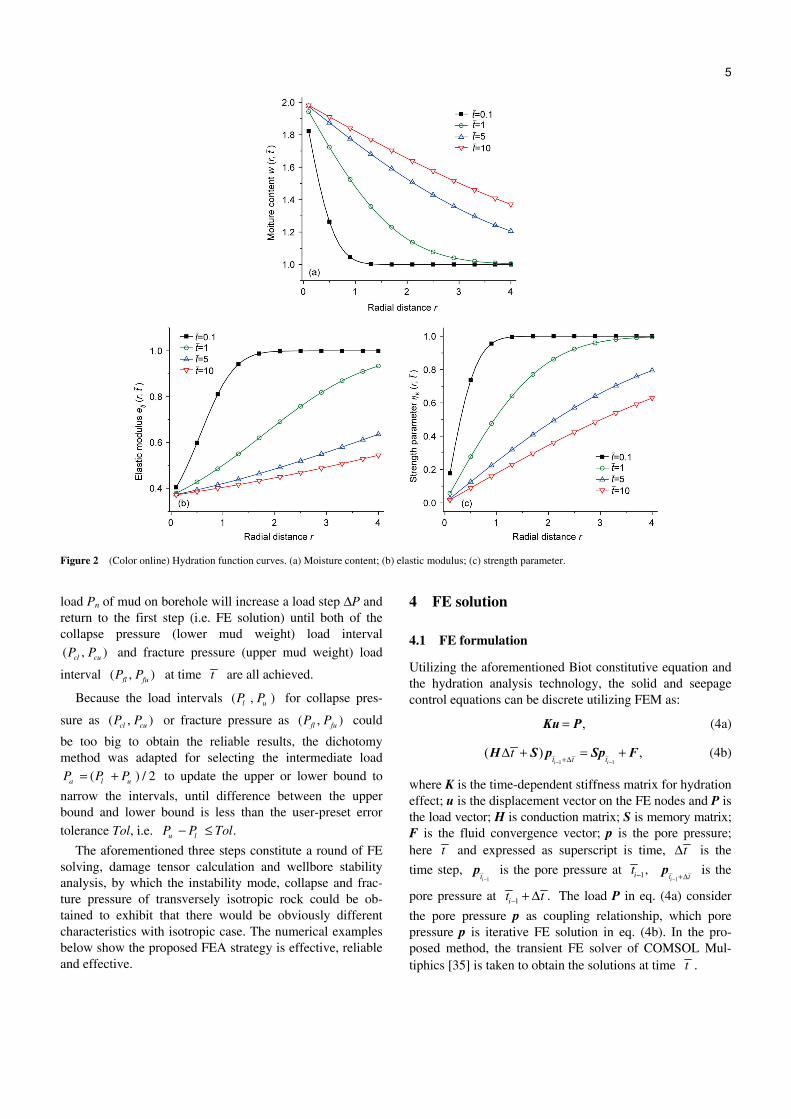
0 0 1ij kw e η∞ = = = and /2 2,dw = the hydration function
curves could be obtained as shown in Figure 2. It can be saw that the moisture content ( , )kw r t is becoming bigger,
elastic modulus ( , )ije r t and strength parameter ( , )k r tη
are becoming smaller as time increasing. At the short hy-dration time 0.1,t = the variables near the wellbore wall significant change obviously, and the surrounding rock ap-pear change as a result of long-term effect. So the chemi-cally active effect of water-sensitive rock need to be con-sidered, and the time-dependent variables should be solved effectively and reliably.
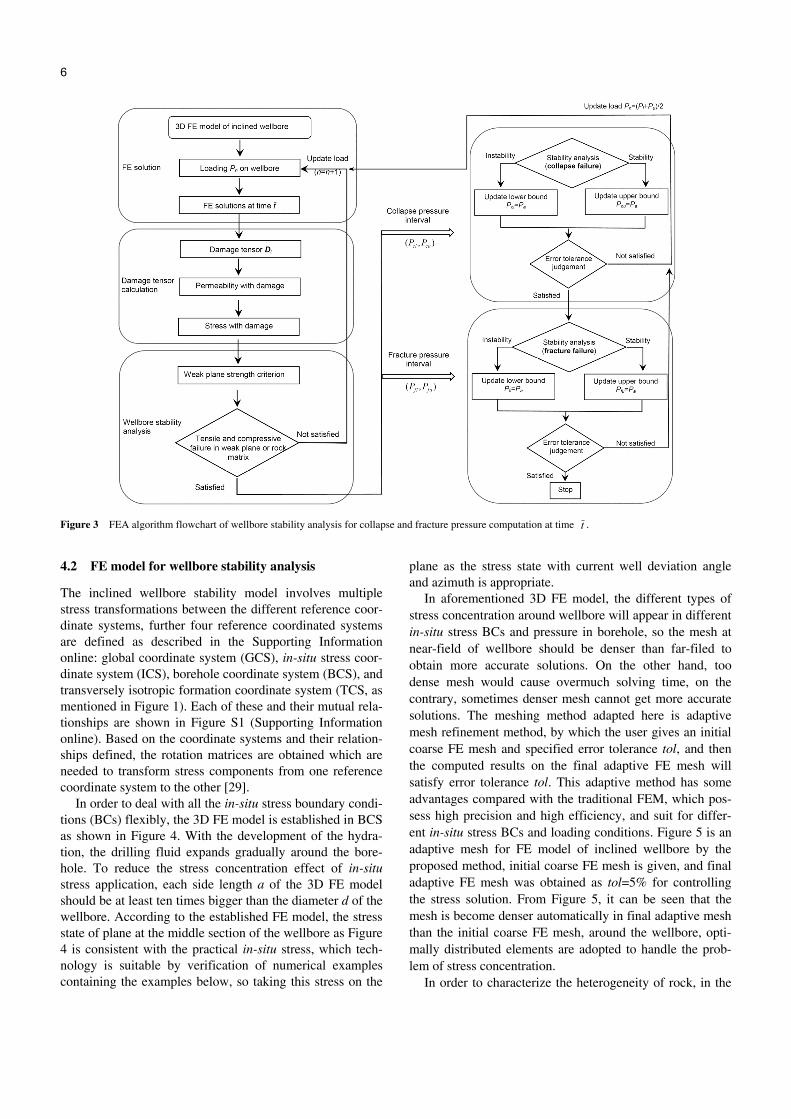
3 FEA strategy
The FEA technology in this paper achieves the results for wellbore stability analysis of transversely isotropic rock with HMCD coupling by implementing the three-step FEA strategy as below, and the corresponding algorithm is illus-trated in Figure 3.
3.1 FE solution
For the wellbore stability problems of laminated rock, the numerical 3D FE model will be established with in-situ stress boundary conditions (BCs) for declined borehole with different inclination and azimuth angle, in which model the rock media consider the hydration effect. Under the current pressure load Pn of mud on borehole, the effective stress
etσ and permeability tk could be calculated to obtain
solutions at time t by the standard FEA technology, as described in Section 4.
3.2 Damage tensor calculation
The aforementioned effective stress etσ and the compres-
sive or tensile strength are used to calculate the damage tensor ,tD and furthermore the stress tσ and permeabil-
ity tκ with damage could be calculated respectively, by
which the damage state of the rock under the current hydra-tion and load could be described in Section 5.
3.3 Wellbore stability analysis
Utilizing the weak pane strength criterion, the stress tσ
with damage will be used to check if the compressive or tensile situation happens in the weak plane and rock matrix of laminated rock as described in Section 6. The pressure
Wang Y L, et al. Sci China Tech Sci January (2016) Vol.59 No.1 5
Figure 2 (Color online) Hydration function curves. (a) Moisture content; (b) elastic modulus; (c) strength parameter.
load Pn of mud on borehole will increase a load step ΔP and return to the first step (i.e. FE solution) until both of the collapse pressure (lower mud weight) load interval ( , )cl cuP P and fracture pressure (upper mud weight) load
interval ( , )fl fuP P at time t are all achieved.
Because the load intervals ( , )l uP P for collapse pres-
sure as ( , )cl cuP P or fracture pressure as ( , )fl fuP P could
be too big to obtain the reliable results, the dichotomy method was adapted for selecting the intermediate load
( ) / 2a l uP P P= + to update the upper or lower bound to
narrow the intervals, until difference between the upper bound and lower bound is less than the user-preset error tolerance Tol, i.e. .u lP P Tol− ≤
The aforementioned three steps constitute a round of FE solving, damage tensor calculation and wellbore stability analysis, by which the instability mode, collapse and frac-ture pressure of transversely isotropic rock could be ob-tained to exhibit that there would be obviously different characteristics with isotropic case. The numerical examples below show the proposed FEA strategy is effective, reliable and effective.
4 FE solution
4.1 FE formulation
Utilizing the aforementioned Biot constitutive equation and the hydration analysis technology, the solid and seepage control equations can be discrete utilizing FEM as:
,=Ku P (4a)
1 1
( ) ,− −+Δ
Δ + = +i it t t
tH S p Sp F (4b)
where K is the time-dependent stiffness matrix for hydration effect; u is the displacement vector on the FE nodes and P is the load vector; H is conduction matrix; S is memory matrix; F is the fluid convergence vector; p is the pore pressure; here t and expressed as superscript is time, tΔ is the
time step, 1−it
p is the pore pressure at 1,it − 1− +Δit t
p is the
pore pressure at 1 .it t− + Δ The load P in eq. (4a) consider
the pore pressure p as coupling relationship, which pore pressure p is iterative FE solution in eq. (4b). In the pro-posed method, the transient FE solver of COMSOL Mul-tiphics [35] is taken to obtain the solutions at time t .
6 Wang Y L, et al. Sci China Tech Sci January (2016) Vol.59 No.1
Figure 3 FEA algorithm flowchart of wellbore stability analysis for collapse and fracture pressure computation at time t .
4.2 FE model for wellbore stability analysis
The inclined wellbore stability model involves multiple stress transformations between the different reference coor-dinate systems, further four reference coordinated systems are defined as described in the Supporting Information online: global coordinate system (GCS), in-situ stress coor-dinate system (ICS), borehole coordinate system (BCS), and transversely isotropic formation coordinate system (TCS, as mentioned in Figure 1). Each of these and their mutual rela-tionships are shown in Figure S1 (Supporting Information online). Based on the coordinate systems and their relation-ships defined, the rotation matrices are obtained which are needed to transform stress components from one reference coordinate system to the other [29].
In order to deal with all the in-situ stress boundary condi-tions (BCs) flexibly, the 3D FE model is established in BCS as shown in Figure 4. With the development of the hydra-tion, the drilling fluid expands gradually around the bore-hole. To reduce the stress concentration effect of in-situ stress application, each side length a of the 3D FE model should be at least ten times bigger than the diameter d of the wellbore. According to the established FE model, the stress state of plane at the middle section of the wellbore as Figure 4 is consistent with the practical in-situ stress, which tech-nology is suitable by verification of numerical examples containing the examples below, so taking this stress on the
plane as the stress state with current well deviation angle and azimuth is appropriate.
In aforementioned 3D FE model, the different types of stress concentration around wellbore will appear in different in-situ stress BCs and pressure in borehole, so the mesh at near-field of wellbore should be denser than far-filed to obtain more accurate solutions. On the other hand, too dense mesh would cause overmuch solving time, on the contrary, sometimes denser mesh cannot get more accurate solutions. The meshing method adapted here is adaptive mesh refinement method, by which the user gives an initial coarse FE mesh and specified error tolerance tol, and then the computed results on the final adaptive FE mesh will satisfy error tolerance tol. This adaptive method has some advantages compared with the traditional FEM, which pos-sess high precision and high efficiency, and suit for differ-ent in-situ stress BCs and loading conditions. Figure 5 is an adaptive mesh for FE model of inclined wellbore by the proposed method, initial coarse FE mesh is given, and final adaptive FE mesh was obtained as tol=5% for controlling the stress solution. From Figure 5, it can be seen that the mesh is become denser automatically in final adaptive mesh than the initial coarse FE mesh, around the wellbore, opti-mally distributed elements are adopted to handle the prob-lem of stress concentration.
In order to characterize the heterogeneity of rock, in the

Wang Y L, et al. Sci China Tech Sci January (2016) Vol.59 No.1 7
Figure 4 (Color online) FE model and stability analysis plane of inclined wellbore with hydration effect.
Figure 5 Mesh refinement for FE model of inclined wellbore. (a) Initial coarse FE mesh; (b) final adaptive FE mesh (tol=5%).
preliminary study of the authors, the model is discrete as many elements by FEM, and the mechanical properties of each node on FE mesh is assumed to conform to a given Weibull distribution as defined in the following probability density function [17].
1
exp , 0,( , , )
0, 0,
η η η η
− − ≥ =
<
m mm x x x
f x m
x
(5)
where x is variable representing the mechanical parameter (such as material modulus or strength), η is scale parameter representing the average range of x, m is shape parameter characterizing the homogeneity degree of x. The material property (i.e. Young’s modulus Eh and Ev, shear modulus Gv, permeability kh and kv) or strength property could describe the heterogeneity of rock, which obey the aforementioned Weibull distribution. The heterogeneity simulation method will be introduced directly in the proposed method of this paper.
5 Damage tensor calculation
In practical engineering, rock is typical brittle material in which damage will occur in some micro-units and expand continuously under load, by continuum damage mechanics, the damage variable describing process of microscopic damage to macroscopic crack deduces the constitutive equation with damage coupling [36]. For wellbore stability problem, ignoring the effect of damage, load-bearing capac-
ity must be overestimated to emerge the instability phe-nomenon, so damage analysis has been introduced to de-scribe the failure behavior of rock. One of the key tech-niques incorporated into this procedure is the technology transfer of damage analysis for rock from recently devel-oped transversely isotropic continuum damage with HMD coupling to HMCD coupling by introducing the hydration effect.
5.1 Damage tensor
The chemically active effect for elastic modulus reduction could be saw as damage evolution, combining the hydration of elastic modulus eq. (3b) and the damage definition of elastic modulus reduction [14], the transversely isotropic damage tensor of hydration could be expressed as:
( ) ( ) ( )
( ) ( ) ,
. ( ).
= =
t t t t t
t t t
t
cx cx y cx z h h v
c h vcy cy z
vcz
D D D h w h w h wD D h w h w
sym h wsym D
D (6)
where Dc is damage tensor of hydration with symmetric property, exp{ }∞= − − − 0.5( ) 1 [ ( , ) ]k e kh w c w r t w is the hy-
dration damage function. For the transversely isotropic medium, the damage may
occur in each principle direction depending on the stress state under the current loud and the anisotropic strength property. In this paper, the uniaxial tensile, compressive and shear strength are introduced and damage variable devel-oped into the damage tensor as [19]:
.
( ) ( ) ( )
( ) ( ) ,
. ( )
η η ηη η
η
= =
t t t t t
t t t
t
mx mx y mx z
m my my z
mz
ha hs vs
ha vs
va
D D D
D D
sym D
g g gg g
sym g
D
(7)

8 Wang Y L, et al. Sci China Tech Sci January (2016) Vol.59 No.1
where exp ]1 2( ) 1 [ ( ) /m mk kg aI Jη η= − − + is the damage
function, I1 and J2 are the first stress invariant and second partial stress invariant respectively, a is the constant in Drucker-Prager (DP) strength criterion; ηk is strength pa-rameter in isotropic plane as ηha or ηhs, in transverse direc-tion as ηva or ηvs respectively; ηha and ηva adopt the uniaxial compressive strength as the medium is compressive ( 0 , 1, 2, 3i iσ≤ = ) in principle direction, and vice versa,
the uniaxial tensile strength would be adapted; ηhs and ηvs are the shear strength in isotropic plane and transverse di-rection respectively, which adopt the 0.8–1.0 times the ten-sile strength [37]. All these aforementioned strength param-eters can be tested by traditional rock mechanical experi-ments.
The damage considering various factors, e.g. stress, chemical and temperature, could form a comprehensive damage variable. Using the hydration damage tensor eq. (6) and stress damage tensor eq. (7), the comprehensive damage tensor could be obtained as:
1 (1 ). (1 ),t c m= − − × −D D D (8)
where 1−Dc represents the subtraction between scalar 1 and each parameter in tensor Dc to form a new tensor with the same number of rows and columns as Dc, which rule goes for Dm and Dt in the same way; the notations “.×” represents the product of each corresponding parameter in two matrix-es, so the coefficients in matrix Dt are operated by the corresponding coefficients in matrixes Dc and Dm with comprehensive consideration the current hydration and stress state.
5.2 Stress and permeability with damage
In TCS, the solutions of effective stress etσ and permeabil-
ity tκ have been computed by FEM in Section 4. Consid-
ering the effect of damage, the effective stress should be reduced by the damage tensor according to the strain equiv-alence principle [38]; the permeability of rock will enhance gradually due to the macroscopic damage generation and expansion, basing on relationship between permeability and strain [17,39], a reliable technology of effective stress and permeability damage evolution is proposed to reflect the damage characteristic as:
e . / (1 ),t t t= −σ σ D (9a)
30. exp ( )( / ) ,t t tγ ϕ ϕ= ×κ κ D (9b)
where the notations “./” represents the division of each cor-responding parameter in two matrixes; e
tσ is effective
stress in TCS; tσ is stress with damage; 1−Dt is the dam-
age item to describe the enhancement characteristic of ef-
fective stress; ϕ0 and ϕ are initial and current porosities re-spectively, γ is the permeability damage coefficient (here γ=0.5), and exp(γDt) is the damage item to describe that the permeability is enhanced by damage. Through some nu-merical examples test including the results given below, eq. (9) describing the damage effect of stress and permeability reveals excellent effect.
6 Wellbore stability analysis based on weak plane strength criterion
The weak plane model is usually considered in most appli-cation cases, assuming a series of weak plane with a given orientation angle within the rock media as shown in Figure 6, a corresponding analytical method could be established. For wellbore stability analysis, the weak plane analytical method adopts Mohr-Coulomb criterion for compressive failure and tensile stress criterion for tensile failure in rock matrix and weak plane (or expressed as isotropic plane) respectively, the strength parameter values in rock matrix are higher than the corresponding values in weak plane. The weak plane strength criterion was introduced here to check the failure or not in laminated medium and using the trans-versely isotropic FE solutions.
The proposed method introduces the below weak plane strength criterion to check the strength for the transversely isotropic rock as:
tensile failure in weak plane
0,σ ≤tz
(10a)
compressive failure in weak plane
w w 31 3
w
2( ),
(1 ctg )sin 2
μ σσ σμ β β
+− ≥−
t t
S (10b)
tensile failure in rock matrix
,θσ σ≤ − t (10c)
compressive failure in rock matrix
2 1/21 3 0 0 3 0 02( )[( 1) ],σ σ μ σ μ μ− ≥ + + + S (10d)
where components of stresses with damage in eq. (10) are all expressed in TCS,
tzσ is the normal stress of weak
Figure 6 Weak plane and deviation angle βt of laminated rock.

Wang Y L, et al. Sci China Tech Sci January (2016) Vol.59 No.1 9
plane (or expressed as stress in transverse direction); 1σ
and 3σ are the first and third principal stresses respec-
tively; θσ is the tangential stress; S0 and Sw are cohesions
in rock matrix and weak plane respectively; μ0 and μw are internal friction coefficients in rock matrix and weak plane respectively; σt is tensile strength in rock matrix. All these aforementioned strength parameters can be tested by tradi-tional rock mechanical experiments. As shown in Figure 4, the stress results of the middle section in 3D FE model with well deviation angle and azimuth represent the stress state under the current pressure load of mud on borehole, so the weak plane criterion is used to check the stress as eq. (10). By increasing current pressure load (mud weight) and re-peating application of the weak plane criterion for wellbore stability analysis, both of the collapse pressure (lower mud weight) and fracture pressure (upper mud weight) could be achieved as described in Section 3.
7 Numerical examples
The proposed analysis strategy has been coded into a Matlab program and partly used the transient FE solver of COMSOL Multiphysics basing on the FEA strategy. This section presents three interrelated numerical examples showing the performance of the procedure. Throughout, the program is run on a DELL OptiPlex 380 Intel(R) Core(TM) 2.93 GHz desktop computer. The first example is chosen to discuss the effectiveness for hydration effect of the pro-posed method with hydraulic-mechanical-chemical (HMC) coupling, by comparing the results of pore pressure and stress of rock surrounding wellbore with the poroelastic analytical method for transverse isotropic and isotropic cas-es. The second example analyzes change around the well-bore under the effect of the hydration effect, and the phe-nomenon of the physical property change over time. In last example, a practical shale engineering case, the collapse cycling time, time-dependent collapse and fracture pressure (safe mud weight) will be computed. In the three examples, the shape parameters m of Weibull distribution for hetero-geneous material property and strength property are set as 5 and constant a in DP strength criterion is set as 0.29; when the FE procedure is implemented, the tetrahedral ele-ment is used and the adaptive error tolerance tol for FE mesh and error tolerance Tol for the upper bound and lower bound of mud weight are all set as 5% throughout.
7.1 Pore pressure and stress analysis of rock sur-rounding wellbore with HMC coupling
In this study, a special case for laminated rock with hydra-tion effect is considered with the axis of material symmetry coinciding with the axis of the wellbore model as shown in
the Figure 7, which analytical solutions exists [40]. The wellbore model was simulating a vertical wellbore to drill into organic-rich Woodford shale formation. The basic physical parameters of the model are listed in the Table 1, in which the parameter μ is the pore fluid viscosity coefficient.
Figure 8 presents pore pressure and effective stress dis-tributions inside the model profile along the direction of the maximum horizontal stress SH (A-B in Figure 7) at 15 min after drilling, as function of the normalized radial distance
/ ( / 2 / 2),r d d− d =300 mm is the diameter of the focus
area, here r is the absolute radial distance form wellbore wall, normalized radial distance of zero and one correspond to the inner boundary and the outer boundary respectively. To further illustrate the effectiveness of the proposed method for this tight rock, results from the poroelastic ana-lytical method for transversely isotropic and isotropic (Eh=Ev=4.2 Gpa, νh=νv=0.3) analyses are included. In order to be more effective for comparison with the poroelastic analytical results, the damage analysis and heterogeneity simulation of the proposed method are not considered in this example, in other words, just with HMC coupling and homogeneous media. It should be noted that the poroelastic analytical method using the generalized plane strain model for transversely isotropic case is just suitable for the the axis of material symmetry coinciding with the axis of the well-bore model, however the proposed numerical method can
Figure 7 Wellbore model with axis coinciding with axis of material symmetry.
Table 1 Physical parameters for example 1
Parameter Value Parameter Value
h (m) 2000 kh (nD) 50 d (mm) 200 kv (nD) 50
Sv (g/cm3) 2.5 φ0 0.15% Sh (g/cm3) 2.0 μ (Pa s) 1.0E-3
SΗ (g/cm3) 2.2 wd/2 0.09
p (MPa) 19.6 ∞w 0.03
P (MPa) 21.4 ch 0.0434 Eh (GPa) 7.4 cv 0.0434 Ev (GPa) 4.2 cε1 0.078
νh 0.13 cε2 11.08
νv 0.30 ce 11
αh 0.85 cν 1.3
αv 0.88

10 Wang Y L, et al. Sci China Tech Sci January (2016) Vol.59 No.1
Figure 8 (Color online) Results comparison at time t =15 min of proposed method and poroelastic analytical method. (a) Pore pressure results; (b) effec-tive radial stress results; (c) effective tangential stress results.
handle the other inclined wellbore cases serving as a general method.
Figure 8(a) shows that the pore pressure results comput-ed by the proposed method is consistent with the results of the poroelastic analytical method, the maximum pore pres-sure 23.5 MPa appear at normal radial distance 0.05 by the hydration effect of the mud activity and the minimum pore pressure blew the initial value 19.6 MPa appear at normal radial distance 0.5 as the result of the maximum horizontal stress. Figure 8(b) and (c) also shows the consistence of the effective radial and tangential stresses results of the pro-posed method with poroelastic analytical results. The radial stress results at normal radial distance about 0.04–0.05 achieve the minimum value, and the tangential stresses re-sults decrease rapidly. Both of the effective radial and tan-gential stresses results at normal radial distance about 0.5 varies smoothly, which are slightly different from the ana-lytic solutions.
7.2 Petrophysical heterogeneity and chemically active effect analysis
The effectiveness of the heterogeneous modeling and hy-dration analysis technologies will be revealed as below uti-
lizing the FE model and the numerical computation in this paper. The geometric model is shown as Figure 5, the input parameters are provided by actual experiments of Longmaxi formation shale in Sichuan province in China as shown in Table 2 [41], cηc and cηϕ are hydration constants for cohe-sion and internal friction coefficient respectively, other hy-dration parameters are the same as Section 7.1. The hetero-geneous model is established using the Weibull distribution
Table 2 Physical parameters for example 2
Parameter Value Parameter Value
h (m) 2500 S0 (MPa) 9.2 d (mm) 215.9 Sw (MPa) 8.56
Sv (g/cm3) 2.49 μ0 0.716 Sh (g/cm3) 2.26 μw 0.41
SΗ (g/cm3) 2.84 αh 0.8
αs (°) N30oE αv 0.7
γt (°) 0o kh (nD) 500 Eh (GPa) 24.91 kv (nD) 200 Ev (GPa) 14.093 φ0 3.7% Gv (GPa) 14.81 σt (MPa) 7
νh 0.26 cηc 58.8
νv 0.3 cηφ 2.8

Wang Y L, et al. Sci China Tech Sci January (2016) Vol.59 No.1 11
with m=5 for initial parameters assignment, i.e. Young’s modulus, shear modulus and permeability. For example, the probability density function of Weibull distribution for Young’s modulus Eh with scale parameter n=24.9 GPa is shown in Figure 9(a). The 3D and the middle slice section of the wellbore model distributed as Figure 9(b) and (c), and it can be seen that the range of the values is about 27–29 GPa, which heterogeneous distribution has good consisten-cy in the whole region. The revolution of some significantly time-dependent results, as moisture content, damage varia-ble, elastic modulus and hydration strain of time t =10, 50 and 100 d, are shown and illustrated in Table 3. The mois-ture content (e.g. w1) around the wellbore uniformly in-creases as the result of the same value as permeability set-ting in the isotropic plane. At time t=100 d, the moisture content extension outward is obvious and the radial distance of hydration almost reach 0.5 m, the damage (e.g. D11) at this time become serious, which would cause the phenome-non of diameter expansion and wellbore failure, so the ex-posed borehole is protected by casing in the actual petrole-um drilling engineering. The Young’s modulus (e.g. e11) is decreasing gradually with the moisture content increasing, which reveal the changing value is homogeneous and striped expansion as the result of the initial heterogeneity of rock. The maximum expansion stain (e.g. Δε11) reach almost 0.06 to influence the stress distribution at the wellbore, which is difficult to be analyzed without considering hydra-tion.
7.3 Time-dependent collapse and fracture pressure computation
This example will discuss the collapse cycling time, the collapse pressure (lower critical mud weight) and fracture pressure (upper critical mud weight) computed by the pro-posed method. The deviation angle of the isotropic plane is βt=0° to reveal its influence on wellbore stability, and the other physical parameters and hydration parameters are the same as Section 7.2 listed in Table 2.
The collapse pressure results of different deviation angle βb=0°, 30°, 60°, 90° at wellbore azimuth αb=30° (the direc-tion of the minimum in-situ stress Sh) are shown in Figure 10. It can be saw that the collapse pressure increase with βb
becoming bigger as the result of Sh. With the time increas-ing, the the collapse pressure results become bigger form smooth value until time reaching about 10 d, which is called the collapse cycling time. In the actual petroleum engineer-ing, drilling fluid density need to increase as the time in-creasing for water-sensitive rock formation, the collapse cycling time need reliably predict to keep real-time wellbore stability.
Figure 11 shows the collapse pressure (lower critical mud weight) and fracture pressure (upper critical mud weight) at time 50 d computed by the proposed method, which polar plots have the symmetry at αb=30°, 210° and αb=120°, 300° (North direction as αb=0°) with respective to the direction of the in-situ stresses due to the deviation an-
Figure 9 (Color online) Heterogeneous distribution of initial Yong’s module Eh/10 GPa. (a) Probability density function of Weibull distribution; (b) 3D model; (c) 2D slice model.

12 Wang Y L, et al. Sci China Tech Sci January (2016) Vol.59 No.1
Table 3 The revolution of time-dependent results, as moisture content, damage variable, elastic modulus and hydration strain
Time t (d) Moisture content w1 Damage variable D11 Young’s modulus e11 (×10 GPa) Hydration strain Δε11 (×10–2)
10
50
100
Figure 10 (Color online) Collapse pressure (lower critical mud weight) results computed by the proposed method at well azimuth αb=30° and different deviation angles of βb=0°, 30°, 60°, 90°.
gle of the isotropic plane setting as βt=0°. It can be saw that both of the collapse and fracture pressure results are bigger in the direction of minimum in-situ stress as αb=30°, 210° than the corresponding values in the direction of maxim in-situ stress as αb=120°, 300°. In Figure 11(a), the collapse pressure become bigger with the deviation angles increasing in the direction of minimum in-situ stress as αb=30°, 210°, on the other hand, the minimum collapse pressure appears almost at deviation angles βb=60° in the direction of maxim in-situ stress as αb=120°, 300°. In Figure 11(b), the fracture
Figure 11 (Color online) Polar plots of (a) collapse pressure (lower criti-cal mud weight) (g/cm3) and (b) fracture pressure (upper critical mud weight) (g/cm3) at time t =50 d computed by the proposed method.
pressure become bigger with the deviation angles increasing in the direction of minimum in-situ stress as αb=30°, 210°, on the other hand, the collapse pressure become smaller with the deviation angles increasing in the direction of maxim in-situ stress as αb=120°, 300°. Comprehensive con-sidering of the above analysis results, the drilling fluid den-sity at each wellbore deviation angle and azimuth of in-clined wellbore needs to be greater than the values in Figure 11(a) and be smaller than the values in Figure 11(b) for op-timizing the drilling direction.

Wang Y L, et al. Sci China Tech Sci January (2016) Vol.59 No.1 13
8 Conclusion
A new FEA technology with HMCD coupling for inclined wellbore stability analysis of transversely isotropic rock have been presented, which successfully has yielded a relia-ble FE procedure that obtains the results surrounding well-bore considering the chemical activity of the drilling fluid by phenomenological hydration behavior, furthermore the collapse cycling time was analyzed and the safe mud weight computation for collapse and fracture pressure were com-puted. For water-sensitive and laminated rock, comprehen-sive utilization of the classic Biot constitutive relation, damage tensor and weak plane strength criterion has de-scribed the anisotropic wellbore failure behavior for being consistent with the property of rock. One of the key tech-niques incorporated into this procedure is the technology transfer of HMD coupling to HMCD coupling by introduc-ing the hydration effect. Results for typical numerical ex-amples have shown that the present HMCD coupling analy-sis could obtain significantly different results from the case not considering the chemical activity of the drilling fluid and possesses the potential for further extension to practical engineering application. Using the FEA technology of the proposed procedure, anisotropic damage evolution and hy-draulic fracturing for rock with multi-fields coupling have made some progresses, which will be reported in future publications.
This work was supported by the National Natural Science Foundation of China (Grant Nos. 11372157, 11302115 & 51608301), the Doctoral Fund of Ministry of Education of China (Grant No. 20120002110075), the Foundation for the Author of National Excellent Doctoral Dissertation of China (Grant No. 201326) and the China Postdoctoral Science Foundation (Grant No. 2015M571030).
Supporting Information
The supporting information is available online at tech.scichina.com and www.springerlink.com. The supporting materials are published as submit-ted, without typesetting or editing. The responsibility for scientific accura-cy and content remains entirely with the authors.
1 Zhuang Z, Liu Z L, Wang Y L. Fundamental theory and key me-
chanical problems of shale oil gas effective extraction (in Chinese). Chin Q Mech, 2015, 33: 8–17
2 Lo T, Coyner K B, Toksöz M N. Experimental determination of elas-tic anisotropy of Berea sandstone, Chicopee shale, and Chelmsford granite. Geophys, 1986, 51: 164–171
3 Abousleiman Y N, Hoang S K, Tran M H. Mechanical characteriza-tion of small shale samples subjected to fluid exposure using the in-clined direct shear testing device. Int J Rock Mech Min Sci, 2010, 47: 355–367
4 Yang H L, Shen R C, Fu L. Composition and mechanical properties of gas shale (in Chinese). Pet Drill Tech, 2013, 41: 31–35
5 Nguyen V X, Abousleiman Y N, Hoang S. Analyses of wellbore in-stability in drilling through chemically active fractured-rock for-mations. SPE J, 2009, 14: 283–301
6 Bažant Z P, Salviato M, Chau V T, et al. Why fracking works. J Appl
Mech, 2014, 81: 1–10 7 Abousleiman Y N, Nguyen V X. PoroMechanics response of inclined
wellbore geometry in fractured porous media. J Eng Mech, 2005, 131: 1170–1183
8 Nguyen V X, Abousleiman Y N. Naturally fractured reservoir three-dimensional analytical modeling: theory and case study. In: SPE Annual Technical Conference and Exhibition. Society of Petro-leum Engineers, 2009
9 Chen S L, Abousleiman Y N. Stress analysis of borehole subjected to fluid injection in transversely isotropic poroelastic medium. Mech Res Commun, 2016, 73: 63–75
10 Hoang S, Abousleiman Y N, Ewy R T. Openhole stability and solids production simulation in emerging reservoir shale using transversely isotropic thick wall cylinders. In: SPE Annual Technical Conference and Exhibition. Society of Petroleum Engineers, 2009
11 Lu Y H, Chen M, Jin Y, et al. A mechanical model of borehole sta-bility for weak plane formation under porous floe. Pet Sci Tech, 2012, 30: 1629–1638
12 Xiao Y, Liu H, Desai C S, et al. Effect of intermediate principal stress ratio on particle breakage of rockfill material. J Geotech Ge-oenviron Eng, 2016, 142: 06015017
13 Zhao Y P, Chen J, Yuan Q, et al. Microcrack connectivity in rocks: a real-space renormalization group approach for 3D anisotropic bond percolation. J Stat Mech: Theory Exp, 2016, 2016: 013205
14 Zhuang Z, Cheng B B. A novel enriched CB shell element method for simulating arbitrary crack growth in pipes. Sci China Phys Mech Astron, 2011, 54: 1520–1531
15 Zeng Q L, Liu Z L, Xu D D, et al. Modeling stationary and moving cracks in shells by X-FEM with CB shell elements. Sci China Tech Sci, 2014, 57: 1276–1284
16 Krajcinovic D, Lemaitre J. Continuum Damage Mechanics Theory and Applications. New York: Springer-Verlag, 1987
17 Zhu W C, Bruhns O T. Simulating excavation damaged zone around a circular opening under hydromechanical conditions. Inter J Rock Mech Min Sci, 2008, 45: 815–830
18 Lu Y L, Elsworth D, Wang L G. Microcrack-based coupled damage and flow modeling of fracturing evolution in permeable brittle rocks. Comput Geotech, 2013, 49: 226–244
19 Wang Y L, Liu Z L, Lin S C, et al. Finite element analysis of seepage in rock based on continuum damage evolution (in Chinese). Eng Mech, 2016, 33: 29–37
20 Wang Y L, Liu Z L, Yang H L, et al. FE analysis of rock with hy-draulic-mechanical coupling based on continuum damage evolution. Math Probl Eng, 2016, doi: 10.1155/2016/8534965
21 Wang Y L, Liu Z L, Yang H L, et al. Finite element analysis for wellbore stability of transversely isotropic rock with hydraulic-mech- anical-damage coupling. Sci China Tech Sci, doi: 10.1007/s11431- 016-6070-x
22 Wang Y L, Zhuang Z, Liu Z L, et al. Finite element analysis of transversely isotropic rock with mechanical-chemical-damage cou-pling. Eng Mech, 2016, doi: 10.6052/j.issn.1000-4750.2016.04.0287
23 Mortara G. A yield criterion for isotropic and cross-anisotropic cohe-sive-frictional materials. Int J Numer Anal Met, 2010, 34: 953–977
24 Xiao Y, Liu H L, Yang G. Formulation of cross-anisotropic failure criterion for granular material. Int J Geomech, 2012, 12: 182–188
25 Hill R. The Mathematical Theory of Plasticity. Oxford: Oxford Uni-versity Press, 1950
26 Pariseau W G. Plasticity theory for anisotropic rocks and soils. In: Proceedings of the 10th U.S. Symposium on Rock Mechanics. American Rock Mechanics Association, 1968. 267–295
27 Lee H, Ong S H, Azeemuddin M, et al. A wellbore stability model for formations with anisotropic rock strengths. J Pet Sci Eng, 2012, 96: 109–119
28 Lee H, Chang C, Ong S H, et al. Effect of anisotropic borehole wall failures when estimating in situ stresses: A case study in the Nankai

14 Wang Y L, et al. Sci China Tech Sci January (2016) Vol.59 No.1
accretionary wedge. Mar Pet Geol, 2013, 48: 411–422 29 Biot M A. General theory of three-dimensional consolidation. J Appl
Phys, 1941, 12: 155–164 30 Biot M A. Theory of stress-strain relations in anisotropic viscoelas-
ticity and relaxation phenomena. J Appl Phys, 1954, 25: 1385–1391 31 Detourmay E, Cheng A H D. Fundamentals of Poroelasticity. Oxford:
Pergamon, 1993 32 Cheng A H D. Material coefficients of anisotropic poroelasticity. In-
ter J Rock Mech Min Sci, 1997, 34: 199–205 33 Dokhani V, Yu M, Takach N E, et al. The role of moisture adsorption
in wellbore stability of shale formations: Mechanism and modeling. J Nat Gas Sci Eng, 2015, 27: 168–177
34 Huang R Z, Chen M, Deng J G, et al. Study on shale stability of wellbore by mechanics coupling with chemistry method (in Chinese). Drill Fluid Compl Fluid, 1995, 12: 15–21
35 COMSOL Multiphysics User’s Guide. Version 5.0. Stockholm:
COMSOL Inc., 2014 36 Jean L. Coupled elasto-plasticity and damage constitutive equations.
Comput Methods Appl Mech Eng, 1985, 51: 31–49 37 Jaeger J C, Cook N G W. Fundamentals of Rock Mechanics. Houston:
Blackwell Publishing, 1983 38 Krajcinovic D. Damage mechanics: Accomplishments, trends and
needs. Inter J Solids Struct, 2000, 37: 267–277 39 Zhu W C, Bruhns O T. Simulating excavation damaged zone around
a circular opening under hydromechanical conditions. Inter J Rock Mech Min Sci, 2008, 45: 815–830
40 Tran M H, Abousleiman Y N. Anisotropic porochemoelectroelastic solution for an inclined wellbore drilled in shale. J Appl Mech, 2013, 80: 020912
41 Yang H L, Chen C W, Wang J H, et al. Technical report of experi-mental study of shale drilling (in Chinese). Beijing: Drilling Research Institute, China National Petroleum Corporation, 2013