scope and design for data warehouse iteration 1 2008
TRANSCRIPT
Scope and Design for Data Warehouse Iteration 1 2008
Contents
1. Introduction1.1 Overview1.2 Scope1.3 Audience1.4 Background for data warehouse design guidelines1.5 Requirements and initial goals of the warehouse1.6 Approach for the derivation of the "star" schema
1.6.1 The star schema1.6.2 The Specifics of Metadata1.6.3 The Concept Model1.6.4 Semantic signatures1.6.5 The case of UML models1.6.6 The pending case of classifications1.6.7 Planned evolution of the model
2. Detailed design of model and ETL processes2.1 Database Model: Entity Relationship Diagram2.2 Database ETL Scripts
Administered Element types: Table AE_TYPEAdministered Elements and their properties: Table ADMINISTERED_ELEMENTRelationship Types: Table RELATIONSHIP_TYPEAdministered Element Relationship pairs: Table AE_ RELATIONSHIPSource parent-child tables for AE_RELATIONSHIPPre-computed Administered Element RelationshipsCoding Schemes: Table CODING_SCHEMEConcepts: Tables CONCEPT, CONCEPT_REL_TYPE and CONCEPT_RELATIONSHIPConcept Usage Types: Table CONCEPT_USAGE_TYPEConcepts and Administered Elements relationships pairs: Table CONCEPT_AEUML Model Classes: Table UML_MOD_CLASS
UML Model Class Attributes: Table UML_MOD_ATTRIBUTEUML Classes Relationship pairs: Table UMC_RELATIONSHIP
Authors: Nadine Azie, JJ Maurer
Email: [email protected], [email protected]
Team: MDR
Contract: 27XS083
Client: National Cancer Institute Center for Bioinformatics National Institutes of Heath US Department of Health and Human Services
1. Introduction
1.1 Overview
A goal of the caDSR is to define a comprehensive set of standardized metadata descriptors for cancer research terminology used in information collection and analysis. Various NCI offices and partner organizations have developed the content of the caDSR by registration of data elements based on data standards, data collection forms, databases, clinical applications, data exchange formats, UML models, and vocabularies. Using the ISO/IEC 11179 model for metadata registration, information about names, definitions, permissible values, and semantic concepts for common data elements (CDEs) have been recorded. The caDSR data model is a complex transactional system that combines the elements of the ISO 11179 model with custom extensions and data structures needed to support tools. At times it is difficult to extract information from the database and only expert personnel can run custom queries and analysis.
To reach a new level of performance and ease of access, a new and simplified model will be needed with the data warehouse technology that has been developed to solve this type of problem. This design is an implementation of a warehouse model for the caDSR and partial EVS data. The first iteration is a prototype to validate the approach and obtain performance measures.
1.2 Scope
1.
2. 3. 4.
5.
6.
7.
8. 9.
This document provides a general description of the concepts of a warehouse for metadata registry objects. The document describes how the models are conceived then provides the design details for a proposed prototype database model that would facilitate metadata searches. The document also includes the detailed mapping of tables and columns in the caDSR to the warehouse model and the description of the ETL process that would be used to populate the prototype model from the source database.
The scope of this document covers only the first iteration of a 5 step plan. The first iteration is a proof of concept design to test the model for functionality and performance. Only off the shelf tools are planned for querying the warehouse in this first iteration.
1.3 Audience
This document is targeted towards an audience that has at least a basic familiarity with the design architecture of the current caDSR database.
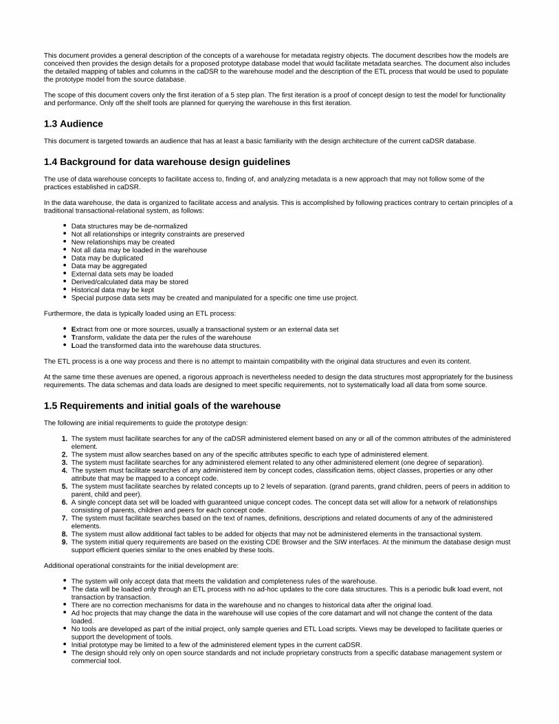
1.4 Background for data warehouse design guidelines
The use of data warehouse concepts to facilitate access to, finding of, and analyzing metadata is a new approach that may not follow some of the practices established in caDSR.
In the data warehouse, the data is organized to facilitate access and analysis. This is accomplished by following practices contrary to certain principles of a traditional transactional-relational system, as follows:
Data structures may be de-normalizedNot all relationships or integrity constraints are preservedNew relationships may be createdNot all data may be loaded in the warehouseData may be duplicatedData may be aggregatedExternal data sets may be loadedDerived/calculated data may be storedHistorical data may be keptSpecial purpose data sets may be created and manipulated for a specific one time use project.
Furthermore, the data is typically loaded using an ETL process:
Extract from one or more sources, usually a transactional system or an external data setTransform, validate the data per the rules of the warehouseLoad the transformed data into the warehouse data structures.
The ETL process is a one way process and there is no attempt to maintain compatibility with the original data structures and even its content.
At the same time these avenues are opened, a rigorous approach is nevertheless needed to design the data structures most appropriately for the business requirements. The data schemas and data loads are designed to meet specific requirements, not to systematically load all data from some source.
1.5 Requirements and initial goals of the warehouse
The following are initial requirements to guide the prototype design:
The system must facilitate searches for any of the caDSR administered element based on any or all of the common attributes of the administered element.The system must allow searches based on any of the specific attributes specific to each type of administered element.The system must facilitate searches for any administered element related to any other administered element (one degree of separation).The system must facilitate searches of any administered item by concept codes, classification items, object classes, properties or any other attribute that may be mapped to a concept code.The system must facilitate searches by related concepts up to 2 levels of separation. (grand parents, grand children, peers of peers in addition to parent, child and peer).A single concept data set will be loaded with guaranteed unique concept codes. The concept data set will allow for a network of relationships consisting of parents, children and peers for each concept code.The system must facilitate searches based on the text of names, definitions, descriptions and related documents of any of the administered elements.The system must allow additional fact tables to be added for objects that may not be administered elements in the transactional system.The system initial query requirements are based on the existing CDE Browser and the SIW interfaces. At the minimum the database design must support efficient queries similar to the ones enabled by these tools.
Additional operational constraints for the initial development are:
The system will only accept data that meets the validation and completeness rules of the warehouse.The data will be loaded only through an ETL process with no ad-hoc updates to the core data structures. This is a periodic bulk load event, not transaction by transaction.There are no correction mechanisms for data in the warehouse and no changes to historical data after the original load.Ad hoc projects that may change the data in the warehouse will use copies of the core datamart and will not change the content of the data loaded.No tools are developed as part of the initial project, only sample queries and ETL Load scripts. Views may be developed to facilitate queries or support the development of tools.Initial prototype may be limited to a few of the administered element types in the current caDSR.The design should rely only on open source standards and not include proprietary constructs from a specific database management system or commercial tool.

1.6 Approach for the derivation of the "star" schema
1.6.1 The star schema
A star model is a type of data model used in data marts and data warehouses to facilitate analysis and reporting of data. Figure 1.6.1a illustrates the components of a star model, which consists of one central fact table "surrounded" by a number of related dimensions tables. The fact is typically a quantitative entity (such as a sales figure) of primary interest to the user. The dimension is a set of qualifying attributes of the fact, stored in a table related by a relational foreign key. The fact can be aggregated by one or more one of its dimensions (location, timeframe, owner, organization, market characteristics).
When the fact is related to another fact, with its own dimensions, the star schema becomes a "snowflake" schema which essentially is a more complex model made up of the several star sub-models.
There are a number of well documented techniques to guide in the design of star schemas and the corresponding queries. If needed temporary star models can be derived from other data in the warehouse to meet specific user needs or purposes.
Figure 1.6.1a: Components of a Star Schema
1.6.2 The Specifics of Metadata
In the database containing metadata as the subject matter data, there is no quantitative figure (as described above in the attributes of the fact table) as the primary object of interest for analysis. So what is the primary object of interest in a metadata registry? The caDSR above all is a registry of objects describing other data. The primary objects of interest are therefore the objects for which the life cycle is tracked and managed. These objects are administered components in the caDSR and labeled administered elements in the MDR warehouse. The object types tracked are:
ClassificationConceptual DomainData Element ConceptData Element
Note on warehouse versus materialized views
A relational view is a query interface presented to the user as a RDBMS table definition. When a view is queried, the user query is combined with the view query to create a compound query accessing the actual base tables containing the data. Most database systems support views, including most open source RDBMS. A materialized view is an actual base table populated by a SQL query. The database administrator defines the refresh interval. The COTS product usually has a mechanism to automatically refresh the derived table. The materialized view can be used to implement a warehouse schema. The ETL process must be expressed in a single SQL query for each view. The materialized view is a COTS product specific feature (in our case ORACLE RDBMS) not supported by open source RDBMS packages. Materialized views are not used in the MDR warehouse design due to the lack of portability to open source products, the limitation of the ETL process and the restrictions to a single COTS data source. Except for ease of set up in a homogeneous environment, (same COTS product and same physical database) the materialized view does not offer any significant advantage over tables loaded through an ETL process, yet they have long term liabilities.
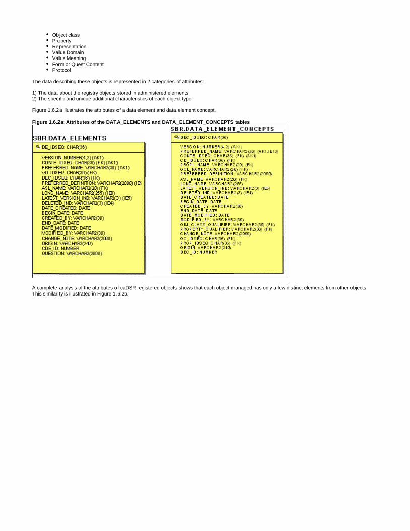
Object classPropertyRepresentationValue DomainValue MeaningForm or Quest ContentProtocol
The data describing these objects is represented in 2 categories of attributes:
1) The data about the registry objects stored in administered elements2) The specific and unique additional characteristics of each object type
Figure 1.6.2a illustrates the attributes of a data element and data element concept.
Figure 1.6.2a: Attributes of the DATA_ELEMENTS and DATA_ELEMENT_CONCEPTS tables
A complete analysis of the attributes of caDSR registered objects shows that each object managed has only a few distinct elements from other objects. This similarity is illustrated in Figure 1.6.2b.

Figure 1.6.2b: Mapping of Elements to Star Schema
The that emerges is therefore the itself. The warehouse design guidelines allow us to de-normalize the objects and create a first fact administered elementcentral fact table for the administered element that contains all the attributes of all registered objects. One of the primary fact tables is therefore a table containing all the administered elements and their combined attributes with one elementary dimension for the Element Type. The warehouse also allows storing of administered elements object types that are not (or not yet) administered components in the caDSR, like Classification Scheme Items.
The second most important information represented in the ISO/IEC 11179 model are the relationships between the administered elements. In the version of the 11179 model used for the caDSR, there are relational constraints enforced between tables containing the data for the individual elements and also relationships enforced through code implementation between the individual element tables and the table containing the administered component information. From a semantic content standpoint these relationships are critical for the identification of related objects and enforce part of the business rules for derivation/make up of other objects.
In the warehouse model the relationships between elements are stored in one table. Each relationship record contains end points (keys) pointing to a "to" and "from" administered element. Each relationship has a Relationship Type. The relationship attributes also collects all the distinct attributes from the caDSR cross reference tables between elements.
The is a for an administered element but also may emerge as a fact in its own right, based on search requirements.relationship fact dimension
Once the structure of elements and their derivation are preserved in the warehouse model, the next most important question is semantic meaning. For the purpose of the warehouse design, the semantic meaning is expressed by the concepts assigned to administered elements.
Figure 1.6.2c illustrates the entities and relationships that describe administered elements. Please note that in this figure, and the subsequent subject area images of the warehouse model, in order to enhance the clarity of the diagrams, only a partial list of attributes is displayed.
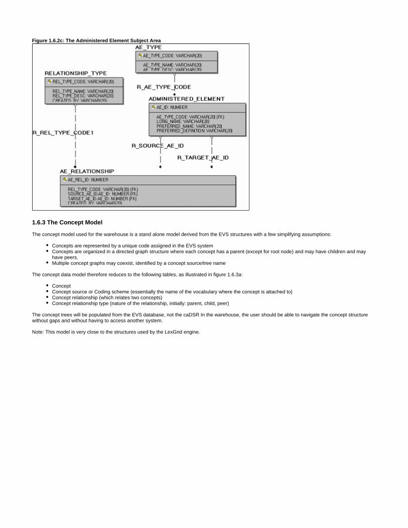
Figure 1.6.2c: The Administered Element Subject Area
1.6.3 The Concept Model
The concept model used for the warehouse is a stand alone model derived from the EVS structures with a few simplifying assumptions:
Concepts are represented by a unique code assigned in the EVS systemConcepts are organized in a directed graph structure where each concept has a parent (except for root node) and may have children and may have peers.Multiple concept graphs may coexist, identified by a concept source/tree name
The concept data model therefore reduces to the following tables, as illustrated in figure 1.6.3a:
ConceptConcept source or Coding scheme (essentially the name of the vocabulary where the concept is attached to)Concept relationship (which relates two concepts)Concept relationship type (nature of the relationship, initially: parent, child, peer)
The concept trees will be populated from the EVS database, not the caDSR In the warehouse, the user should be able to navigate the concept structure without gaps and without having to access another system.
Note: This model is very close to the structures used by the LexGrid engine.

Figure 1.6.3b Diagram of the LexGrid model
The table in Appendix B describes the results of a comparative analysis between the LexGrid and caMDR model tables.
The analysis shows that the warehouse Concept model is compatible with LexGrid and can easily be expanded, as needed, to match the level of granularity of the LexGrid model.
In the warehouse model, the concepts are related to administered elements by a concept usage table and a concept usage type, as seen in figure 1.6.3c. This simple and flexible mechanism bridges the registry object model to the concept model.
Characterization of administered elements by concepts
One of the major purposes of the caDSR is to support semantic interoperability of information systems in the Cancer Bio Informatics Grid. The NCICB has spent considerable effort in assigning concept codes to objects stored in the caDSR in such a way that objects with identical or like meaning can be found and interoperability can be achieved.
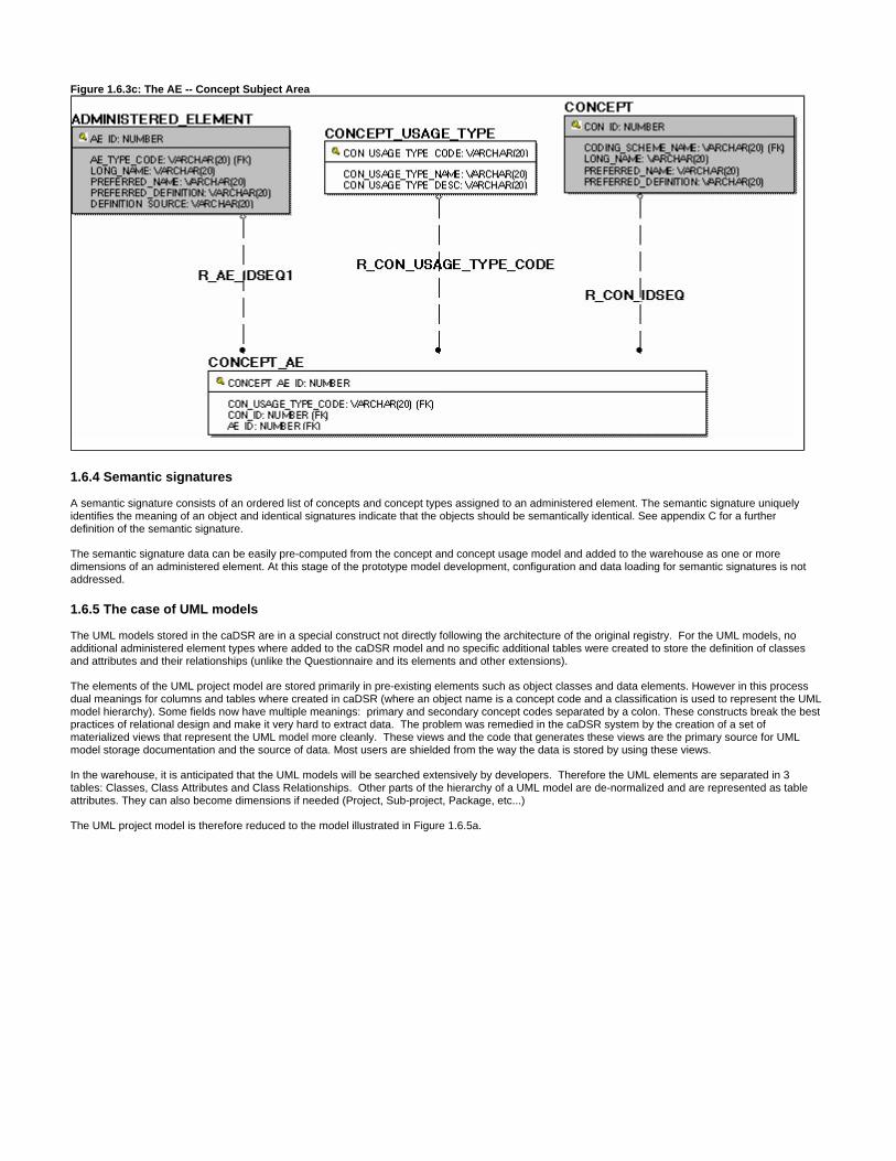
Figure 1.6.3c: The AE -- Concept Subject Area
1.6.4 Semantic signatures
A semantic signature consists of an ordered list of concepts and concept types assigned to an administered element. The semantic signature uniquely identifies the meaning of an object and identical signatures indicate that the objects should be semantically identical. See appendix C for a further definition of the semantic signature.
The semantic signature data can be easily pre-computed from the concept and concept usage model and added to the warehouse as one or more dimensions of an administered element. At this stage of the prototype model development, configuration and data loading for semantic signatures is not addressed.
1.6.5 The case of UML models
The UML models stored in the caDSR are in a special construct not directly following the architecture of the original registry. For the UML models, no additional administered element types where added to the caDSR model and no specific additional tables were created to store the definition of classes and attributes and their relationships (unlike the Questionnaire and its elements and other extensions).
The elements of the UML project model are stored primarily in pre-existing elements such as object classes and data elements. However in this process dual meanings for columns and tables where created in caDSR (where an object name is a concept code and a classification is used to represent the UML model hierarchy). Some fields now have multiple meanings: primary and secondary concept codes separated by a colon. These constructs break the best practices of relational design and make it very hard to extract data. The problem was remedied in the caDSR system by the creation of a set of materialized views that represent the UML model more cleanly. These views and the code that generates these views are the primary source for UML model storage documentation and the source of data. Most users are shielded from the way the data is stored by using these views.
In the warehouse, it is anticipated that the UML models will be searched extensively by developers. Therefore the UML elements are separated in 3 tables: Classes, Class Attributes and Class Relationships. Other parts of the hierarchy of a UML model are de-normalized and are represented as table attributes. They can also become dimensions if needed (Project, Sub-project, Package, etc...)
The UML project model is therefore reduced to the model illustrated in Figure 1.6.5a.
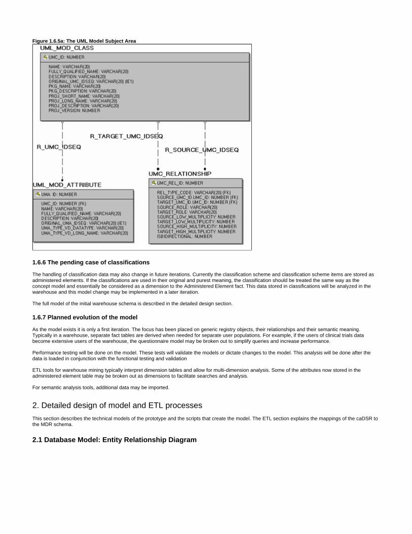
Figure 1.6.5a: The UML Model Subject Area
1.6.6 The pending case of classifications
The handling of classification data may also change in future iterations. Currently the classification scheme and classification scheme items are stored as administered elements. If the classifications are used in their original and purest meaning, the classification should be treated the same way as the concept model and essentially be considered as a dimension to the Administered Element fact. This data stored in classifications will be analyzed in the warehouse and this model change may be implemented in a later iteration.
The full model of the initial warehouse schema is described in the detailed design section.
1.6.7 Planned evolution of the model
As the model exists it is only a first iteration. The focus has been placed on generic registry objects, their relationships and their semantic meaning. Typically in a warehouse, separate fact tables are derived when needed for separate user populations. For example, if the users of clinical trials data become extensive users of the warehouse, the questionnaire model may be broken out to simplify queries and increase performance.
Performance testing will be done on the model. These tests will validate the models or dictate changes to the model. This analysis will be done after the data is loaded in conjunction with the functional testing and validation
ETL tools for warehouse mining typically interpret dimension tables and allow for multi-dimension analysis. Some of the attributes now stored in the administered element table may be broken out as dimensions to facilitate searches and analysis.
For semantic analysis tools, additional data may be imported.
2. Detailed design of model and ETL processes
This section describes the technical models of the prototype and the scripts that create the model. The ETL section explains the mappings of the caDSR to the MDR schema.
2.1 Database Model: Entity Relationship Diagram
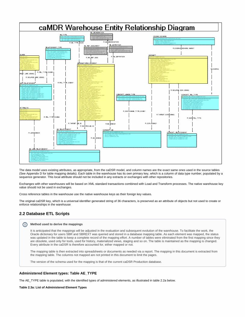
The data model uses existing attributes, as appropriate, from the caDSR model, and column names are the exact same ones used in the source tables (See Appendix D for table mapping details). Each table in the warehouse has its own primary key, which is a column of data type number, populated by a sequence generator. This local attribute should not be included in any extracts or exchanges with other repositories.
Exchanges with other warehouses will be based on XML standard transactions combined with Load and Transform processes. The native warehouse key value should not be used in exchanges.
Cross reference tables in the warehouse use the native warehouse keys as their foreign key values.
The original caDSR key, which is a universal identifier generated string of 36 characters, is preserved as an attribute of objects but not used to create or enforce relationships in the warehouse
2.2 Database ETL Scripts
Administered Element types: Table AE_TYPE
The AE_TYPE table is populated, with the identified types of administered elements, as illustrated in table 2.2a below.
Table 2.3a: List of Administered Element Types
Method used to derive the mappings
It is anticipated that the mappings will be adjusted in the evaluation and subsequent evolution of the warehouse. To facilitate the work, the Oracle dictionary for users SBR and SBREXT was queried and stored in a database mapping table. As each element was mapped, the status was updated in the table to keep a complete record of the mapping effort. A number of tables were eliminated from the first mapping since they are obsolete, used only for tools, used for history, materialized views, staging and so on. The table is maintained as the mapping is changed. Every attribute in the caDSR is therefore accounted for, either mapped or not.
The mapping table is then extracted into spreadsheets or documents as needed via a report. The mapping in this document is extracted from the mapping table. The columns not mapped are not printed in this document to limit the pages.
The version of the schema used for the mapping is that of the current caDSR Production database.
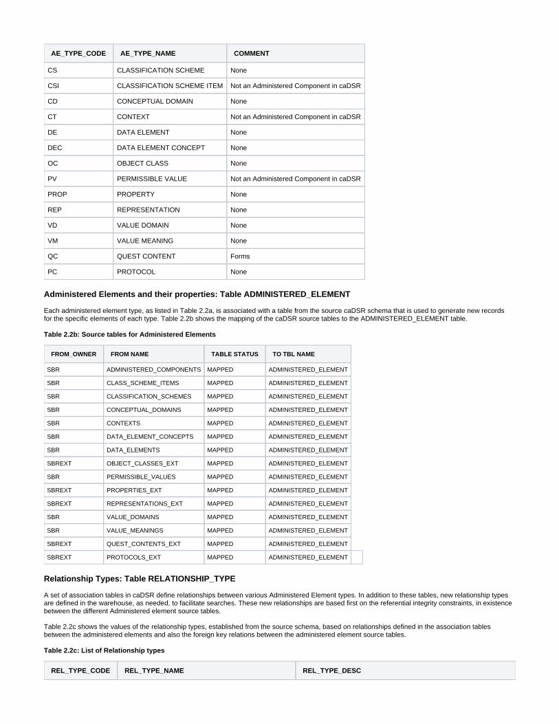
AE_TYPE_CODE AE_TYPE_NAME COMMENT
CS CLASSIFICATION SCHEME None
CSI CLASSIFICATION SCHEME ITEM Not an Administered Component in caDSR
CD CONCEPTUAL DOMAIN None
CT CONTEXT Not an Administered Component in caDSR
DE DATA ELEMENT None
DEC DATA ELEMENT CONCEPT None
OC OBJECT CLASS None
PV PERMISSIBLE VALUE Not an Administered Component in caDSR
PROP PROPERTY None
REP REPRESENTATION None
VD VALUE DOMAIN None
VM VALUE MEANING None
QC QUEST CONTENT Forms
PC PROTOCOL None
Administered Elements and their properties: Table ADMINISTERED_ELEMENT
Each administered element type, as listed in Table 2.2a, is associated with a table from the source caDSR schema that is used to generate new records for the specific elements of each type. Table 2.2b shows the mapping of the caDSR source tables to the ADMINISTERED_ELEMENT table.
Table 2.2b: Source tables for Administered Elements
FROM_OWNER FROM NAME TABLE STATUS TO TBL NAME
SBR ADMINISTERED_COMPONENTS MAPPED ADMINISTERED_ELEMENT
SBR CLASS_SCHEME_ITEMS MAPPED ADMINISTERED_ELEMENT
SBR CLASSIFICATION_SCHEMES MAPPED ADMINISTERED_ELEMENT
SBR CONCEPTUAL_DOMAINS MAPPED ADMINISTERED_ELEMENT
SBR CONTEXTS MAPPED ADMINISTERED_ELEMENT
SBR DATA_ELEMENT_CONCEPTS MAPPED ADMINISTERED_ELEMENT
SBR DATA_ELEMENTS MAPPED ADMINISTERED_ELEMENT
SBREXT OBJECT_CLASSES_EXT MAPPED ADMINISTERED_ELEMENT
SBR PERMISSIBLE_VALUES MAPPED ADMINISTERED_ELEMENT
SBREXT PROPERTIES_EXT MAPPED ADMINISTERED_ELEMENT
SBREXT REPRESENTATIONS_EXT MAPPED ADMINISTERED_ELEMENT
SBR VALUE_DOMAINS MAPPED ADMINISTERED_ELEMENT
SBR VALUE_MEANINGS MAPPED ADMINISTERED_ELEMENT
SBREXT QUEST_CONTENTS_EXT MAPPED ADMINISTERED_ELEMENT
SBREXT PROTOCOLS_EXT MAPPED ADMINISTERED_ELEMENT
Relationship Types: Table RELATIONSHIP_TYPE
A set of association tables in caDSR define relationships between various Administered Element types. In addition to these tables, new relationship types are defined in the warehouse, as needed, to facilitate searches. These new relationships are based first on the referential integrity constraints, in existence between the different Administered element source tables.
Table 2.2c shows the values of the relationship types, established from the source schema, based on relationships defined in the association tables between the administered elements and also the foreign key relations between the administered element source tables.
Table 2.2c: List of Relationship types
REL_TYPE_CODE REL_TYPE_NAME REL_TYPE_DESC
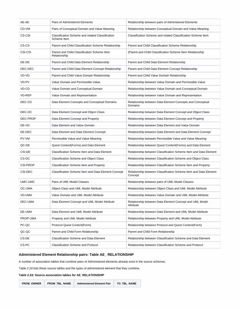
AE-AE Pairs of Administered Elements Relationship between pairs of Administered Elements
CD-VM Pairs of Conceptual Domain and Value Meaning Relationship between Conceptual Domain and Value Meaning
CS-CSI Classification Scheme and related Classification Scheme Item
Classification Scheme and related Classification Scheme Item
CS-CS Parent and Child Classification Scheme Relationship Parent and Child Classification Scheme Relationship
CSI-CSI Parent and Child Classification Scheme Item Relationship
{Parent and Child Classification Scheme Item Relationship
DE-DE Parent and Child Data Element Relationship Parent and Child Data Element Relationship
DEC-DEC Parent and Child Data Element Concept Relationship Parent and Child Data Element Concept Relationship
VD-VD Parent and Child Value Domain Relationship Parent and Child Value Domain Relationship
VD-PV Value Domain and Permissible Value Relationship between Value Domain and Permissible Value
VD-CD Value Domain and Conceptual Domain Relationship between Value Domain and Conceptual Domain
VD-REP Value Domain and Representation Relationship between Value Domain and Representation
DEC-CD Data Element Concepts and Conceptual Domains Relationship between Data Element Concepts and Conceptual Domains
DEC-OC Data Element Concept and Object Class Relationship between Data Element Concept and Object Class
DEC-PROP Data Element Concept and Property Relationship between Data Element Concept and Property
DE-VD Data Element and Value Domain Relationship between Data Element and Value Domain
DE-DEC Data Element and Data Element Concept Relationship between Data Element and Data Element Concept
PV-VM Permissible Value and Value Meaning Relationship between Permissible Value and Value Meaning
QC-DE Quest Content(Forms) and Data Element Relationship between Quest Content(Forms) and Data Element
CSI-DE Classification Scheme Item and Data Element Relationship between Classification Scheme Item and Data Element
CS-OC Classification Scheme and Object Class Relationship between Classification Scheme and Object Class
CSI-PROP Classification Scheme Item and Property Relationship between Classification Scheme Item and Property
CSI-DEC Classification Scheme Item and Data Element Concept Relationship between Classification Scheme Item and Data Element Concept
UMC-UMC Pairs of UML Model Classes Relationship between pairs of UML Model Classes
OC-UMA Object Class and UML Model Attribute Relationship between Object Class and UML Model Attribute
VD-UMA Value Domain and UML Model Attribute Relationship between Value Domain and UML Model Attribute
DEC-UMA Data Element Concept and UML Model Attribute Relationship between Data Element Concept and UML Model Attribute
DE-UMA Data Element and UML Model Attribute Relationship between Data Element and UML Model Attribute
PROP-UMA Property and UML Model Attribute Relationship between Property and UML Model Attribute
PC-QC Protocol Quest Content(Form) Relationship between Protocol and Quest Content(Form)
QC-QC Parent and Child Form Relationship Parent and Child Form Relationship
CS-DE Classification Scheme and Data Element Relationship between Classification Scheme and Data Element
CS-PC Classification Scheme and Protocol Relationship between Classification Scheme and Protocol
Administered Element Relationship pairs: Table AE_ RELATIONSHIP
A number of association tables that combine pairs of Administered elements already exist in the source schemas.
Table 2.2d lists these source tables and the types of administered element that they combine.
Table 2.2d: Source association tables for AE_RELATIONSHIP
FROM_OWNER FROM_TBL_NAME Administered Element Pair TO_TBL_NAME
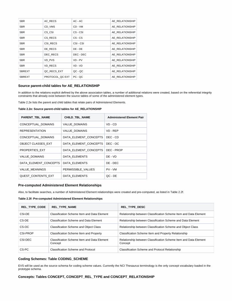
SBR AC_RECS AC - AC AE_RELATIONSHIP
SBR CD_VMS CD - VM AE_RELATIONSHIP
SBR CS_CSI CS - CSI AE_RELATIONSHIP
SBR CS_RECS CS - CS AE_RELATIONSHIP
SBR CSI_RECS CSI CSI- AE_RELATIONSHIP
SBR DE_RECS DE - DE AE_RELATIONSHIP
SBR DEC_RECS DEC - DEC AE_RELATIONSHIP
SBR VD_PVS VD - PV AE_RELATIONSHIP
SBR VD_RECS VD - VD AE_RELATIONSHIP
SBREXT QC_RECS_EXT QC - QC AE_RELATIONSHIP
SBREXT PROTOCOL_QC EXT PC - QC AE_RELATIONSHIP
Source parent-child tables for AE_RELATIONSHIP
In addition to the relations explicit defined by the above association tables, a number of additional relations were created, based on the referential integrity constraints that already exist between the source tables of some of the administered element types.
Table 2.2e lists the parent and child tables that relate pairs of Administered Elements.
Table 2.2e: Source parent-child tables for AE_RELATIONSHIP
PARENT_TBL_NAME CHILD_TBL_NAME Administered Element Pair
CONCEPTUAL_DOMAINS VALUE_DOMAINS VD - CD
REPRESENTATION VALUE_DOMAINS VD - REP
CONCEPTUAL_DOMAINS DATA_ELEMENT_CONCEPTS DEC - CD
OBJECT CLASSES_EXT DATA_ELEMENT_CONCEPTS DEC - OC
PROPERTIES_EXT DATA_ELEMENT_CONCEPTS DEC - PROP
VALUE_DOMAINS DATA_ELEMENTS DE - VD
DATA_ELEMENT_CONCEPTS DATA_ELEMENTS DE - DEC
VALUE_MEANINGS PERMISSIBLE_VALUES PV - VM
QUEST_CONTENTS_EXT DATA_ELEMENTS QC - DE
Pre-computed Administered Element Relationships
Also, to facilitate searches, a number of Administered Element relationships were created and pre-computed, as listed in Table 2.2f.
Table 2.3f: Pre-computed Administered Element Relationships
REL_TYPE_CODE REL_TYPE_NAME REL_TYPE_DESC
CSI-DE Classification Scheme Item and Data Element Relationship between Classification Scheme Item and Data Element
CS-DE Classification Scheme and Data Element Relationship between Classification Scheme and Data Element
CS-OC Classification Scheme and Object Class Relationship between Classification Scheme and Object Class
CSI-PROP Classification Scheme Item and Property Classification Scheme Item and Property Relationship
CSI-DEC Classification Scheme Item and Data Element Concept
Relationship between Classification Scheme Item and Data Element Concept
CS-PC Classification Scheme and Protocol Classification Scheme and Protocol Relationship
Coding Schemes: Table CODING_SCHEME
EVS will be used as the source schema for coding scheme values. Currently the NCI Thesaurus terminology is the only concept vocabulary loaded in the prototype schema.
Concepts: Tables CONCEPT, CONCEPT_REL_TYPE and CONCEPT_RELATIONSHIP

The concept hierarchy is populated from the EVS vocabulary (NCI Thesaurus) used in the caDSR. The hierarchy contains the entire set of EVS concepts from the vocabulary. caDSR elements are then cross mapped to the EVS concepts. Concepts referenced in the caDSR that do not map to the EVS terms will be considered data quality issues and may not be loaded.
Concept Usage Types: Table CONCEPT_USAGE_TYPE
So far, concept usage types as pertaining to concepts and administered elements relationships in caDSR, describe the concept derivation rules that are used to handle concepts, as unique or composite values. So from the source caDSR schema, concept usage types are loaded as distinct values of the context derivation rules found in table SBREXT.CON_DERIVATION_RULES_EXT.
Currently the only three concept derivation rules defined in caDSR are: Simple Concept, Compound and Concatenation.
Concepts and Administered Elements relationships pairs: Table CONCEPT_AE
In the source schema, Administered Element records are associated to specific concepts via foreign key relationships with an association table called COMPONENT_CONCEPTS_EXT, which combine concepts using concept derivation rules.
UML Model Classes: Table UML_MOD_CLASS
Attributes for UML Model classes, the class attribute characteristics and the relationship between classes, are derived from the SBREXT materialized views that contain the UML model components.
Tables 2.2f, 2.2g and 2.2k show the mapping of the UML Model class, class attribute and class relationship tables.
Table 2.2f: Source tables for UML_MOD_CLASS
FROM_OWNER FROM\ NAME* TABLE MAP STATUS TO TBL NAME
SBREXT UP_CADSR_PROJECT_MVW MAPPED UML_MOD_CLASS
SBREXT UP_CLASS_METADATA_MVW MAPPED UML_MOD_CLASS
SBREXT UP_CLASS_METADATA_MVW_TEMP MAPPED UML_MOD_CLASS
SBREXT UP_PACKAGES_MVW MAPPED UML_MOD_CLASS
SBREXT UP_PACKAGES_MVW_TEMP MAPPED UML_MOD_CLASS
UML Model Class Attributes: Table UML_MOD_ATTRIBUTE
Table 2.2g: Source tables for UML_MOD_ATTRIBUTE
FROM_OWNER FROM TBL NAME TABLE_MAP STATUS TO TBL NAME
SBREXT UP_ATTRIBUTE_METADATA_MVW MAPPED UML_MOD_ATTRIBUTE
SBREXT UP_ATTRIBUTE_METADATA_MVW_TEMP MAPPED UML_MOD_ATTRIBUTE
SBREXT UP_ATTRIBUTE_TYPE_METADATA_MVW MAPPED UML_MOD_ATTRIBUTE
UML Classes Relationship pairs: Table UMC_RELATIONSHIP
Table 2.2k: Source tables for UMC_RELATIONSHIP
FROM_OWNER FROM_TBL_NAME TABLE_MAP_STATUS TO_TBL_NAME
SBREXT UP_ASSOCIATIONS_METADATA_MVW | MAPPED UMC_RELATIONSHIP
SBREXT UP_GEN_METADATA_MVW MAPPED UMC_RELATIONSHIP