scope of services for consulting engineering services · 2019-06-27 · limits: sr 581 (bruce b....
TRANSCRIPT

EXHIBIT A
SCOPE OF SERVICES
FOR
FINANCIAL PROJECT ID: 441099-1-32-01
FEDERAL PROJECT NO. D719-034-B
SR 581 (BRUCE B. DOWNS BLVD.) AT SR 54
DISTRICT SEVEN
PASCO COUNTY
Revised: 06/26/19
06/24/19

FP ID: 441099-1-32-01
i
TABLE OF CONTENTS
1 PURPOSE __________________________________________________________________________ A-1
2 PROJECT DESCRIPTION ____________________________________________________________ A-2
3 PROJECT COMMON AND PROJECT GENERAL TASKS _______________________________ A-15
4 ROADWAY ANALYSIS _____________________________________________________________ A-21
5 ROADWAY PLANS _________________________________________________________________ A-24
6 DRAINAGE ANALYSIS _____________________________________________________________ A-25
7 UTILITIES ________________________________________________________________________ A-27
8 ENVIRONMENTAL PERMITS _______________________________________________________ A-27
9 STRUCTURES – SUMMARY AND MISC. TASKS AND DRAWINGS ______________________ A-32
10 STRUCTURES – BRIDGE DEVELOPMENT REPORT ___________________________________ A-33
11 STRUCTURES – TEMPORARY BRIDGE ______________________________________________ A-33
12 STRUCTURES – SHORT SPAN CONCRETE BRIDGE __________________________________ A-33
13 STRUCTURES – MEDIUM SPAN CONCRETE BRIDGE _________________________________ A-33
14 STRUCTURES – STRUCTURAL STEEL BRIDGE ______________________________________ A-33
15 STRUCTURES – SEGMENTAL CONCRETE BRIDGES _________________________________ A-33
16 STRUCTURES – MOVABLE SPAN ___________________________________________________ A-33
17 STRUCTURES – RETAINING WALL _________________________________________________ A-33
18 STRUCTURES - MISCELLANEOUS __________________________________________________ A-33
19 SIGNING AND PAVEMENT MARKING ANALYSIS ____________________________________ A-35
20 SIGNING AND PAVEMENT MARKING PLANS ________________________________________ A-36
21 SIGNALIZATION ANALYSIS ________________________________________________________ A-38
22 SIGNALIZATION PLANS ___________________________________________________________ A-40
23 LIGHTING ANALYSIS ______________________________________________________________ A-41
24 LIGHTING PLANS _________________________________________________________________ A-43
25 LANDSCAPE ARCHITECTURE ANALYSIS ___________________________________________ A-44
26 LANDSCAPE ARCHITECTURE PLANS _______________________________________________ A-44
27 SURVEY __________________________________________________________________________ A-44
28 PHOTOGRAMMETRY ______________________________________________________________ A-49
29 MAPPING _________________________________________________________________________ A-49
30 TERRESTRIAL MOBILE LiDAR _____________________________________________________ A-49
31 ARCHITECTURE DEVELOPMENT – N/A _____________________________________________ A-50
32 NOISE BARRIERS IMPACT DESIGN ASSESSMENT IN THE DESIGN PHASE _____________ A-50
33 INTELLIGENT TRANSPORTATION SYSTEMS ANALYSIS _____________________________ A-50
34 INTELLIGENT TRANSPORTATION SYSTEMS PLANS _________________________________ A-50
35 GEOTECHNICAL __________________________________________________________________ A-51

FP ID: 441099-1-32-01
ii
36 3D MODELING ____________________________________________________________________ A-51
37 PROJECT REQUIREMENTS ________________________________________________________ A-52
38 INVOICING LIMITS ________________________________________________________________ A-53

Stage II A-1 June 26, 2019
SCOPE OF SERVICES FOR CONSULTING ENGINEERING SERVICES
HIGHWAY AND BRIDGE/STRUCTURAL DESIGN
This Exhibit forms an integral part of the agreement between the State of Florida Department of Transportation
(hereinafter referred to as the DEPARTMENT or FDOT) and ______________________ (hereinafter referred to as
the CONSULTANT) relative to the transportation facility described as follows:
Financial Project ID: 441099-1-32-01
Federal Aid Project No.: D719-034-B
County Section No.: 14610 000
Description: SR 581 (Bruce B. Downs Blvd.) At SR 54
Pasco County
Bridge No(s): N/A
Railroad Crossing No(s): N/A
Context Classification: C2 Rural: MP 4.313 - 4.505
C3C Suburban Commercial: PM 4.505 – 4.509
1 PURPOSE
The purpose of this Exhibit is to describe the scope of work and the responsibilities of the CONSULTANT
and the DEPARTMENT in connection with the design and preparation of a complete set of construction
contract documents and incidental engineering services, as necessary, for improvements to the
transportation facility described herein.
Major Work Mix includes: Intersection Improvement
Major Work Types include: 3.1
Minor Work Types include: 4.1.1, 6.3.1, 7.1, 7.2, 7.3, 8.1 and 8.2
Known Alternative/Innovative Construction Contracting Methods: None at this time
The general objective is for the CONSULTANT to prepare a set of contract documents including plans,
specifications, supporting engineering analysis, calculations and other technical documents in accordance
with FDOT policy, procedures and requirements. These Contract documents will be used by the
construction contractor to build the project and test the project components. These Contract documents will
be used by the DEPARTMENT or its Construction Engineering Inspection (CEI) representatives for
inspection and final acceptance of the project. The CONSULTANT shall follow a systems engineering
process to ensure that all required project components are included in the development of the Contract
documents and the project can be built as designed and to specifications.
The Scope of Services establishes which items of work in the FDOT Design Manual and other pertinent
manuals are specifically prescribed to accomplish the work included in this contract, and also indicates
which items of work will be the responsibility of the CONSULTANT and/or the DEPARTMENT. Where
a type of service is noted herein to be provided by the DEPARTMENT, the CONSULTANT shall
communicate to the DEPARTMENT in writing the specific nature of such DEPARTMENT services as
are necessary to support the CONSULTANT’s responsibilities under this contract, and shall do so by
such time as will support the DEPARTMENT’s original project schedule or any subsequent
DEPARTMENT-approved revisions thereto.
The CONSULTANT shall be aware that as a project is developed, certain modifications and/or
improvements to the original concepts may be required. The CONSULTANT shall incorporate these
refinements into the design and consider such refinements to be an anticipated and integral part of the
work. This shall not be a basis for any supplemental fee request(s).
The CONSULTANT shall demonstrate good project management practices while working on this project.
These include communication with the DEPARTMENT and others as necessary, management of time and

FP ID: 441099-1-32-01
Stage II June 26, 2019
A-2
resources, and documentation. The CONSULTANT shall set up and maintain throughout the design of the
project a contract file in accordance with DEPARTMENT procedures. CONSULTANTs are expected to
know the laws and rules governing their professions and are expected to provide services in accordance
with current regulations, codes, ordinances and recognized standards applicable to such professional
services. The CONSULTANT shall provide qualified technical and professional personnel to perform to
DEPARTMENT standards and procedures, the duties and responsibilities assigned under the terms of this
agreement. The CONSULTANT shall minimize to the maximum extent possible the DEPARTMENT’s
need to apply its own resources to assignments authorized by the DEPARTMENT.
The DEPARTMENT will provide contract administration, management services and technical reviews of
all work associated with the development and preparation of contract documents, including Construction
documents. The DEPARTMENT’s technical reviews are for high-level conformance and are not meant to
be comprehensive reviews. The CONSULTANT shall be fully responsible for all work performed and
work products developed under this Scope of Services. The DEPARTMENT may provide job-specific
information and/or functions as outlined in this contract, if favorable.
2 PROJECT DESCRIPTION
The CONSULTANT shall investigate the status of the project and become familiar with concepts and
commitments (typical sections, alignments, etc.) developed from prior studies and/or activities, including
applicable documents at http://fdotd7studies.com. If a Preliminary Engineering Report is available from a
prior or current Project Development and Environmental (PD&E) study, the CONSULTANT shall use the
approved concepts as a basis for the design unless otherwise noted herein or directed by the
DEPARTMENT.
The project generally proposes operational and safety improvements at the CR 581 (Bruce B. Downs
Blvd.) intersections with SR 54 and Eagleston Blvd.
At the option of the CONSULTANT with the approval of the DEPARTMENT Project Manager, this
project may be designed and delivered using either 1) Autodesk AutoCAD Civil 3D 2014, or the
DEPARTMENT’s current Autodesk AutoCAD Civil 3D standard, or 2) Bentley MicroStation GEOPAK
Corridor Modeler, or the DEPARTMENT’s current MicroStation/GEOPAK Corridor Modeler
standard. See http://www.dot.state.fl.us/ecso/main/Version/CurrentVersions.shtm for current versions of
acceptable software. In either case, the project shall be designed, delivered and signed and sealed in
compliance with the DEPARTMENT’s CADD Manual published at
http://www.fdot.gov/cadd/downloads/publications/CADDManual/default.shtm. The DEPARTMENT
provides a “State Kit” for both Autodesk and Bentley products that can be downloaded
fromhttp://www.fdot.gov/cadd/downloads/software/FDOT2017CADDSoftware.shtm.
The CONSULTANT shall deliver a Three-Dimensional (3D) Model of the design project in accordance
with the specifications/criteria defined within the CADD Manual, specifically in Chapter 8 (Section
8.4.2.).
2.1 Project General and Roadway (Activities 3, 4 and 5)
Public Involvement:
Community Awareness Plan
Elected Officials Design Phase Submittal Notification:
An email notification will be sent from the District Secretary to local elected officials at each phase review.
YES NO - Explain:
Maintenance of Access Plan (business & residential): - Access to the State Highway System will be maintained.
Local events will be considered when implementing the MOT plan.
FP ID: 441099-1-32-01
Stage II June 26, 2019
A-3
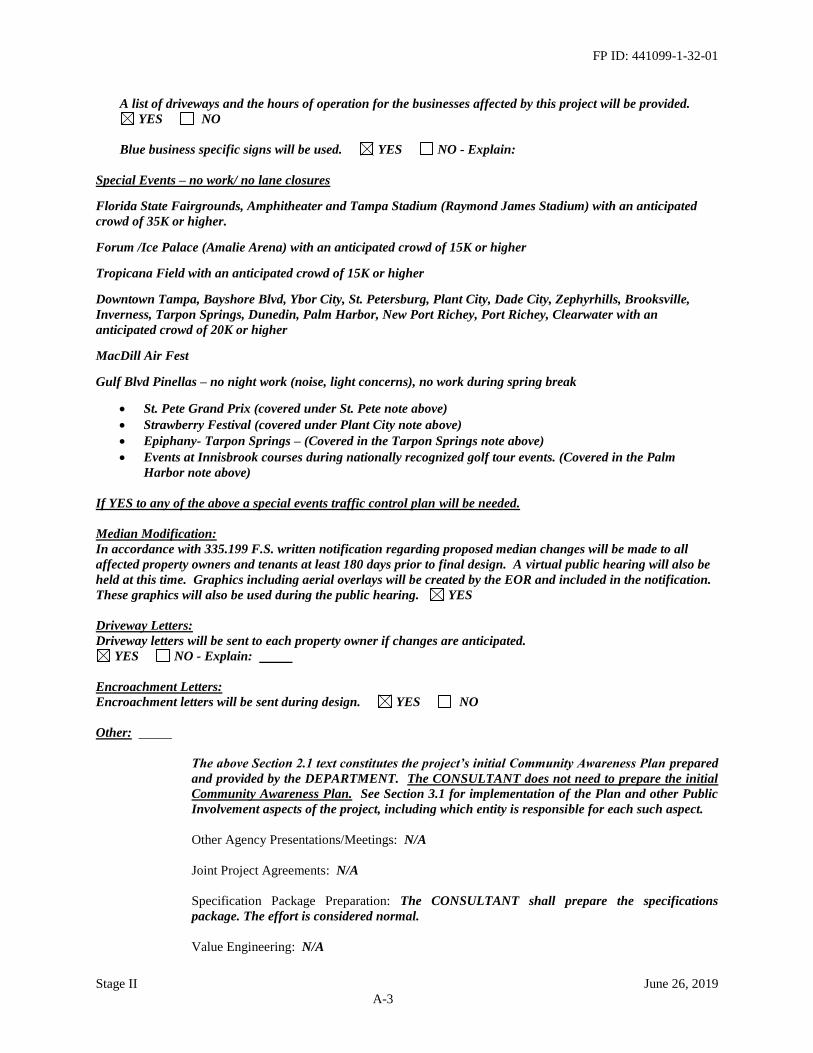
A list of driveways and the hours of operation for the businesses affected by this project will be provided.
YES NO
Blue business specific signs will be used. YES NO - Explain:
Special Events – no work/ no lane closures
Florida State Fairgrounds, Amphitheater and Tampa Stadium (Raymond James Stadium) with an anticipated
crowd of 35K or higher.
Forum /Ice Palace (Amalie Arena) with an anticipated crowd of 15K or higher
Tropicana Field with an anticipated crowd of 15K or higher
Downtown Tampa, Bayshore Blvd, Ybor City, St. Petersburg, Plant City, Dade City, Zephyrhills, Brooksville,
Inverness, Tarpon Springs, Dunedin, Palm Harbor, New Port Richey, Port Richey, Clearwater with an
anticipated crowd of 20K or higher
MacDill Air Fest
Gulf Blvd Pinellas – no night work (noise, light concerns), no work during spring break
• St. Pete Grand Prix (covered under St. Pete note above)
• Strawberry Festival (covered under Plant City note above)
• Epiphany- Tarpon Springs – (Covered in the Tarpon Springs note above)
• Events at Innisbrook courses during nationally recognized golf tour events. (Covered in the Palm
Harbor note above)
If YES to any of the above a special events traffic control plan will be needed.
Median Modification:
In accordance with 335.199 F.S. written notification regarding proposed median changes will be made to all
affected property owners and tenants at least 180 days prior to final design. A virtual public hearing will also be
held at this time. Graphics including aerial overlays will be created by the EOR and included in the notification.
These graphics will also be used during the public hearing. YES
Driveway Letters:
Driveway letters will be sent to each property owner if changes are anticipated.
YES NO - Explain:
Encroachment Letters:
Encroachment letters will be sent during design. YES NO
Other:
The above Section 2.1 text constitutes the project’s initial Community Awareness Plan prepared
and provided by the DEPARTMENT. The CONSULTANT does not need to prepare the initial
Community Awareness Plan. See Section 3.1 for implementation of the Plan and other Public
Involvement aspects of the project, including which entity is responsible for each such aspect.
Other Agency Presentations/Meetings: N/A
Joint Project Agreements: N/A
Specification Package Preparation: The CONSULTANT shall prepare the specifications
package. The effort is considered normal.
Value Engineering: N/A

FP ID: 441099-1-32-01
Stage II June 26, 2019
A-4
Risk Assessment Workshop: N/A
Plan Type: The roadway plans shall be prepared in a Plan format. Profile sheets shall be
provided, if necessary, to show the vertical controls that are needed for the construction of these
projects. The plan (and profile) sheets shall be plotted at a horizontal scale of 1" = 40'.
Limits: SR 581 (Bruce B. Downs Blvd.) At SR 54 (MP 4.313 to 4.509). Project Length = 0.196
miles.
Typical Section: Six lane divided with 22 foot raised, curbed median, 12 foot travel lanes, 4 foot
bike lanes, curb and gutter, 10 foot sidewalk on the west side with ditch, and ditch on the east
side. A new sidewalk on the east side of the roadway within existing right-of-way may be
authorized for design via Optional Services.
Close the first full median opening on CR 581 north of Eagleston Blvd., extend the existing
northbound left turn lane at CR 581/SR 54, and provide an exclusive southbound-to-
northbound U-turn lane at CR 581/Eagleston Blvd, with a surface mill and resurface following
these roadway improvements. See Section 2.7.
Pavement Design: Two pavement designs expected, one for median widening and one for
milling and resurfacing.
Pavement Type Selection Report(s): N/A
Cross Slope: N/A
Access Management Classification: N/A
Transit Route Features: On an existing or planned (adopted) bus route roadway, coordinate with
the transit agency and design as requested their proposed engineering and right-of-way-
feasible, ADA-compliant bus landing pads, rider shelter pads and incidental universal sidewalk
connections, etc. All transit agency contact shall be coordinated in advance with the
DEPARTMENT’s Public Transit Coordinator.
Major Intersections/Interchanges: CR 581 at SR 54 and CR 581 at Eagleston Blvd.
Roadway Alternative Analysis: N/A
Level of TTCP Plans: I
Temporary Signals: N/A
Temporary Lighting: N/A
Temporary Drainage: Some activities proposed by this project will necessitate temporary
drainage. Temporary drainage design shall be performed to ensure the project site drains
adequately during all phases of construction. The placement of temporary traffic control
devices shall be reviewed to ensure that conveyance of runoff is not impeded.
Design Variations/Exceptions: Design variation and/or exception requests shall be prepared for
any situations not meeting current DEPARTMENT and/or FHWA requirements, as
appropriate. The CONSULTANT shall prepare design Variation and Exception reports for the
purpose of estimating design and construction needs based on initial observations. The
CONSULTANT shall recommend, to the DEPARTMENT, either correction of any deficiencies,
or obtaining the appropriate design variations or exceptions, including applicable benefit-cost

FP ID: 441099-1-32-01
Stage II June 26, 2019
A-5
analyses, in accordance with DEPARTMENT procedures. Currently known or suspected
features requiring analysis include: Cross Slope
Back of Sidewalk Profiles: N/A
Selective Clearing and Grubbing: N/A
2.2 Drainage (Activities 6a and 6b)
System Type: The project generally consists of median modifications and milling and
resurfacing between Eagleston Blvd and SR 54. The existing drainage system includes both
open ditches and a closed system with curb inlets that convey runoff to a stormwater
management facility. Existing Environmental Resource Permit (ERP) No. 43030052.001 was
issued by the Southwest Florida Water Management District (SWFWMD) in 2008. One cross
drain has been identified within the project limits; impacts due to the project are not
anticipated. The exact number of cross drains and potential extensions shall be the
responsibility of the CONSULTANT. The cross drain evaluation shall consider alternatives to
extending a cross drain and shall be based upon horizontal clearances, clear zone criteria,
barrier costs, cross drain costs and risk.
The project area is shown on Federal Emergency Management Agency (FEMA) Flood
Insurance Rate Map (FIRM) Number 12101C0426F dated September 26, 2014. The FIRM
shows Zone AE floodplains within the project limits. The CONSULTANT shall determine
floodplain impacts and provide compensation within the FDOT right-of-way.
A search of the DEPARTMENT’S District 7 Flood Data Inventory found no active flooding
complaints within the project limits.
The general goals for the project drainage design are as follows:
• Identify existing drainage issues and provide the most cost-effective solution that is
commensurate with project scope.
• Enhance the safety level of the drainage structures.
• Replace or repair structurally deficient drainage features, consistent with Practical
Design Guidelines.
• Ensure existing drainage features are not adversely impacted by the project.
The CONSULTANT shall perform a visual inspection of the drainage system and consult with
the DEPARTMENT’S Maintenance Office to determine if desilting is needed. In addition, a
structural inventory shall be taken throughout the project limits and review the project during a
rain event. Document any deficiencies and recommendations and present to the
DEPARTMENT in the form of a Drainage Design Documentation Memorandum. Minutes of a
meeting with the Maintenance Office shall be provided in the documentation.
The CONSULTANT shall notify the DEPARTMENT if video inspection of the storm sewer
system is recommended. Video inspection services will be performed by others under a
DEPARTMENT Districtwide or Continuing Services video inspection contract. Within three
weeks following the Notice-To-Proceed, the CONSULTANT shall provide to the
DEPARTMENT figures showing the locations of the pipes to be inspected, and shall quantify
the length and pipe sizes for the required work. Prior to the first phase submittal of plans, the
CONSULTANT shall review the inspection report and provide to the DEPARTMENT
recommendations and construction cost estimates for any pipe repair. The design
implementation of any approved recommendations not included in this Scope of Services may
be added to the Agreement as an Optional Service.
2.3 Utilities Coordination (Activity 7)

FP ID: 441099-1-32-01
Stage II June 26, 2019
A-6
All necessary Utility Coordination will be performed by the DEPARTMENT.
Utilities anticipated on the project: The DEPARTMENT’s Utility Permit search found 6 UAO’s:
Bright House Networks, Frontier Florida LLC, MCI Verizon Business, Pasco County Utilities,
TECO Peoples Gas, and Withlacoochee River Electric Cooperative. The Sunshine 811 design
ticket was used for reference, with the DEPARTMENT’s Permit search used as a control for
coordination. Other controls include field review, phone contacts and as-built plans for
previous projects.
Pursuant to Section 4.5, the CONSULTANT EOR(s) shall develop a utility conflict matrix for
each phase submittal. If the EOR chooses to assign the development of the conflict matrix to the
Utility Coordination Manager, the EOR shall review the conflict matrix for accuracy and
quality control.
The EOR shall review and sign the Utility Work Schedules prior to sending them to the
DEPARTMENT for review and signature.
The EOR(s) for all disciplines that have the potential to affect utility facilities shall meet prior to
any scheduled Utility Design Meeting to ensure that the potential conflicts are understood by
the Utility Coordination Manager, that changes to the plans from the last submittal/Utility
Design Meeting are understood, and that the project schedule and critical dates are adequately
provided to the Utility Coordination Manager. The EORs of all disciplines affecting utility
facilities shall meet with representatives from the District Utility Office and District
Construction Office for a constructability and utility work schedule review meeting prior to the
Phase IV submittal.
2.4 Environmental Permits, Compliances, and Clearances (Activities 8a and 8b
No environmental permits are anticipated for this project.
2.5 Structures (Activities 9 – 18)
Bridge(s): N/A
Retaining Walls: N/A
Noise Barrier Walls: N/A
Miscellaneous: Design a new box span strain pole traffic signal at the CR 581 (Bruce B Downs
Blvd) at Eagleston Blvd. intersection.
2.6 Signing and Pavement Markings (Activities 19 & 20)
Add northbound and southbound multi-post “Eagleston Blvd NEXT SIGNAL” advance street
name signs (2 guide signs total).
The existing lane use control sign and overhead guide sign structure 14S268 shall remain.
The CONSULTANT shall prepare the signing and pavement marking design file to include all
necessary design elements and all associated reference files.
2.7 Signalization (Activities 21 & 22)
Intersections: Design a new box span strain pole traffic signal at the CR 581 (Bruce B Downs
Blvd) at Eagleston Blvd. intersection.

FP ID: 441099-1-32-01
Stage II June 26, 2019
A-7
The design shall accommodate a potential future east leg, as well as this project’s proposed
southbound U-turn movement.
The CONSULTANT shall design for the installation of conduit and fiber optic interconnect
along the west side of CR 581 from Eagleston Blvd. to SR 54, an approximate distance of 1/4
mile. The fiber optic cable trunkline shall be 144 strand single mode fiber optic cable and
connect from the splice vault on the southeast corner of the SR 54 and CR 581 intersection to
the proposed splice vault at the new Eagleston Blvd. signal, with a drop cable to the new signal
controller cabinet at Eagleston. The CONSULTANT shall design the installation of one CCTV
at a location coordinated with Pasco County Traffic Operations.
Traffic Data Collection: N/A
Traffic Studies: N/A
Portable Traffic Monitoring Sites or Stations: The existing PTMS 145507 at MP 4.2 will not be
re-installed. The site shall be located along CR 581 to avoid roadway geometry where turn
lanes exist.
2.8 Lighting (Activities 23 & 24)
The CONSULTANT shall add intersection lighting at CR 581 (Bruce B Downs Blvd) and
Eagleston Blvd.
The CONSULTANT shall coordinate with the DEPARTMENT Project Manager to confirm
that the local government with jurisdiction will commit to maintaining or funding the
maintenance of the additional highway lighting provided by this project, and to confirm the
required number of load centers in advance of initiating plans preparation. Such confirmation
must come directly from the local government, not from a private power company. If the
CONSULTANT fails to perform this coordination in a timely manner, any necessary re-design
and plans revisions resulting therefrom shall be prepared by the CONSULTANT without
additional compensation or extensions of schedule milestones.
2.9 Landscape Architecture (Activities 25 & 26) – N/A
2.10 Survey (Activity 27a except as otherwise noted)
Design Survey:
The CONSULTANT shall provide horizontal and vertical project control (NAD 1983, 1990
adjustment & NAVD 1988); recover/re-establish the historic alignment; reference the
alignment and all control points; may utilize aerial or terrestrial LiDAR targets; provide 3D
topographic/DTM survey through the project limits; perform a drainage survey; and provide a
jurisdiction line survey and geotechnical support as required.
The final Survey Line shall be recorded in field books furnished by the CONSULTANT. Field
books shall be 6-1/2" by 8-3/4" cross section book with 10 by 10 grid on both sides of opening.
Project Network Control (PNC) Sheets shall be prepared depicting the horizontal project
control, the vertical project control, the alignment, and the alignment reference points. The
sheet(s) shall be on a standard 24” x 36” FDOT title block, and shall not be signed and sealed
on the face of the map.
The methodology that is proposed to perform and prepare the topographic/DTM survey is at the
discretion of the CONSULTANT. This methodology must be approved by the District Surveying
and Mapping Dept., the District Location Surveyor, or his designee. When utilizing

FP ID: 441099-1-32-01
Stage II June 26, 2019
A-8
conventional survey instruments and technologies, the CONSULTANT shall follow the Florida
Department of Transportation Surveying and Mapping Procedure, Topic No. 550-030-101. If
Terrestrial Static LiDAR instruments and technologies are utilized, the CONSULTANT shall
follow the applicable FDOT Terrestrial Mobile LiDAR Surveying & Mapping Guidelines, found
in the Surveying & Mapping Handbook.
Subsurface Utility Exploration (Activity 27b): All such necessary services will be provided by the
DEPARTMENT.
Right-of-Way Survey: N/A
Vegetation Survey: N/A
2.11 Photogrammetry (Activity 28) – N/A
2.12 Mapping (Activity 29) – N/A
2.13 Terrestrial Mobile LiDAR (Activity 30)
If Terrestrial Mobile LiDAR instruments and technologies are utilized, the CONSULTANT
shall follow the FDOT Terrestrial Mobile LiDAR Surveying & Mapping Guidelines.
2.14 Architecture (Activity 31) – N/A
2.15 Noise Barriers (Activity 32) – N/A
2.16 Intelligent Transportation Systems (Activities 33 & 34) – N/A
2.17 Geotechnical (Activity 35)
The DEPARTMENT will provide all necessary Geotechnical services for this project. The
CONSULTANT shall request from the DEPARTMENT all Geotechnical data and
recommendations necessary for this project by such time as will support the DEPARTMENT’s
original project schedule or any subsequent DEPARTMENT-approved revisions thereto.
2.18 3D Modeling (Activity 36)
The CONSULTANT shall deliver the Phase II, III and Final 3D Model.
2.19 Project Schedule
Within ten (10) days after the Notice-To-Proceed, and prior to the CONSULTANT beginning
work, the CONSULTANT shall provide a detailed project activity/event schedule for
DEPARTMENT and CONSULTANT scheduled activities required to meet the current
DEPARTMENT Production Date. The schedule shall be based upon the current anticipated
“Production Date” of September 24, 2021 (subject to change). The schedule shall be
accompanied by an anticipated payout and fiscal progress curve. For the purpose of scheduling,
the CONSULTANT shall allow for a four week review time for each phase submittal and any
other submittals as appropriate.
The schedule shall indicate all required submittals.
Periodically, throughout the life of the contract, the project schedule and payout and fiscal
progress curves shall be reviewed, and with the approval of the DEPARTMENT, adjusted as
necessary to incorporate changes in the Scope of Services, project milestones and progress to date.

FP ID: 441099-1-32-01
Stage II June 26, 2019
A-9
The approved schedule and schedule status report, along with progress and payout curves, shall be
submitted with the monthly progress report.
The schedule shall be submitted in an FDOT system-compatible format.
The above schedule submittal shall reflect project-specific input from each affected
DEPARTMENT discipline, including Permits, Utilities, Right-of-Way, and Modal Planning and
Development (noise walls, etc.). The CONSULTANT shall be responsible for ensuring that
such input is received and reviewed with the DEPARTMENT Project Manager in advance.
2.20 Submittals
The CONSULTANT shall furnish construction contract documents as required by the
DEPARTMENT to adequately control, coordinate, and approve the work concepts. The
CONSULTANT shall distribute submittals as directed by the DEPARTMENT. The
DEPARTMENT will determine the specific number of copies required prior to each submittal.
All plans and specifications deliverables provided for herein shall support a fully electronic
advertisement, bidding and letting process for the construction contract in a manner acceptable
to the DEPARTMENT, including compliance with Section 131 of the FDOT Design Manual
and with the CADD Manual. In addition to any required hard copies, the CONSULTANT shall
provide .pdf files for all plans phase submittals thru Phase III. Beginning with the Phase IV
submittal, the CONSULTANT shall provide the electronic CADD files. In addition to any
required hard-copies, all other documents that require DEPARTMENT review shall be
submitted in an electronic medium acceptable to the DEPARTMENT Project Manager,
including processing through the Department’s Electronic Review and Comment system (ERC).
The CONSULTANT shall provide a Constructability and Biddability review of the design with
the Phase III or other designated plans submittal. The CONSULTANT’s comments and
responses developed from this review shall be forwarded to the DEPARTMENT's Construction
Services Unit.
The CONSULTANT shall have their Quality Control, Quality Assurance and applicable
Constructability documents complete and available for review by the DEPARTMENT at the
time of each phase submittal.
The DEPARTMENT reserves the right to visit the premises of the CONSULTANT at any time
to review the project’s status, upon one-hour’s notice.
2.21 Provisions for Work
All work shall be prepared with English units in accordance with the latest editions of standards
and requirements utilized by the DEPARTMENT which include, but are not limited to,
publications such as:
▪ General
o Title 29, Part 1910, Standard 1910.1001, Code of Federal Regulations (29 C.F.R. 1910.1001)
– Asbestos Standard for Industry, U.S. Occupational Safety and Health Administration
(OSHA)
o 29 C.F.R. 1926.1101 – Asbestos Standard for Construction, OSHA
o 40 C.F.R. 61, Subpart M - National Emission Standard for Hazardous Air Pollutants
(NESHAP), Environmental Protection Agency (EPA)
o 40 C.F.R. 763, Subpart E – Asbestos-Containing Materials in Schools, EPA
o 40 C.F.R. 763, Subpart G – Asbestos Worker Protection, EPA
o Americans With Disabilities Act (ADA) Standards for Accessible Design

FP ID: 441099-1-32-01
Stage II June 26, 2019
A-10
o AASHTO – A Policy on Design Standards Interstate System
o AASHTO – Roadside Design Guide
o AASHTO – Roadway Lighting Design Guide
o AASHTO – A Policy for Geometric Design of Highways and Streets
o AASHTO – Highway Safety Manual
o Rule Chapter 5J-17, Florida Administrative Code (F.A.C.), Standards of Practice for
Professional Surveyors and Mappers
o Chapter 469, Florida Statutes (F.S.) – Asbestos Abatement
o Rule Chapter 62-257, F.A.C., Asbestos Program
o Rule Chapter 62-302, F.A.C., Surface Water Quality Standards
o Code of Federal Regulations (C.F.R.)
o Florida Administrative Codes (F.A.C.)
o Chapters 20, 120, 215, 455, Florida Statutes (F.S.) – Florida Department of Business &
Professional Regulations Rules
o Florida Department of Environmental Protection Rules
o FDOT Basis of Estimates Manual
o FDOT Computer Aided Design and Drafting (CADD) Manual
o FDOT Standard Plans
o FDOT Flexible Pavement Design Manual
o FDOT - Florida Roundabout Guide
o FDOT Handbook for Preparation of Specifications Package
o FDOT Standard Plans Instructions
o FDOT Manual of Uniform Minimum Standards for Design, Construction and Maintenance
for Streets and Highways (“Florida Greenbook”)
o FDOT Materials Manual
o FDOT Pavement Type Selection Manual
o FDOT Design Manual
o FDOT Procedures and Policies
o FDOT Procurement Procedure 001-375-030, Compensation for Consultant Travel Time on
Professional Services Agreements
o FDOT Project Development and Environmental Manual
o FDOT Project Traffic Forecasting Handbook
o FDOT Public Involvement Handbook
o FDOT Rigid Pavement Design Manual
o FDOT Standard Specifications for Road and Bridge Construction
o FDOT Utility Accommodation Manual
o Manual on Speed Zoning for Highways, Roads, and Streets in Florida
o Federal Highway Administration (FHWA) - Manual on Uniform Traffic Control Devices
(MUTCD)
o FHWA – National Cooperative Highway Research Program (NCHRP) Report 672,
Roundabouts: An Informational Guide
o FHWA Roadway Construction Noise Model (RCNM) and Guideline Handbook
o Florida Fish and Wildlife Conservation Commission - Standard Manatee Construction
Conditions 2005
o Florida Statutes (F.S.)
o Florida’s Level of Service Standards and Guidelines Manual for Planning
o Model Guide Specifications – Asbestos Abatement and Management in Buildings, National
Institute for Building Sciences (NIBS)
o Quality Assurance Guidelines
o Safety Standards
o Any special instructions from the DEPARTMENT
▪ Roadway
o FDOT – Florida Intersection Design Guide
o FDOT - Project Traffic Forecasting Handbook
o FDOT - Quality/Level of Service Handbook

FP ID: 441099-1-32-01
Stage II June 26, 2019
A-11
o Florida’s Level of Service Standards and Highway Capacity Analysis for the SHS
o Transportation Research Board (TRB) - Highway Capacity Manual
▪ Permits
o Chapter 373, F.S. – Water Resources
o US Fish and Wildlife Service Endangered Species Programs
o Florida Fish and Wildlife Conservation Commission Protected Wildlife Permits
o Bridge Permit Application Guide, COMDTPUB P16591.3C
o Building Permit
▪ Drainage
o FDOT Drainage Design Guide
o FDOT Drainage Manual
o FDOT Erosion and Sediment Control Manual
o FDOT Drainage Connection Permit Handbook
o FDOT Bridge Scour Manual
▪ Survey and Mapping
o All applicable Florida Statutes and Administrative Codes
o Applicable Rules, Guidelines Codes and authorities of other Municipal, County, State and
Federal Agencies.
o Florida Department of Transportation Surveying and Mapping Procedure Topic 550-030-101
o Florida Department of Transportation Surveying and Mapping Handbook
o Florida Department of Transportation Right of Way Procedures Manual
▪ Traffic Engineering and Operations and ITS
o AASHTO - An Information Guide for Highway Lighting
o AASHTO - Guide for Development of Bicycle Facilities
o FHWA Standard Highway Signs Manual
o FDOT Manual on Uniform Traffic Studies (MUTS)
o FDOT Median Handbook
o FDOT Traffic Engineering Manual
o National Electric Safety Code
o National Electrical Code
▪ Florida’s Turnpike Enterprise
o Florida’s Turnpike Plans Preparation and Practices Handbook (TPPPH)
o Florida’s Turnpike Lane Closure Policy
o Florida’s Turnpike Drainage Manual Supplement
o Rigid Pavement Design Guide for Toll Locations with Electronic Toll Collection
o Flexible Pavement Design Guide for Toll Locations with Electronic Toll Collection
o Florida’s Turnpike General Tolling Requirements (GTR)
o Additional Florida’s Turnpike Enterprise standards, guides, and policies for design and
construction can be found on the FTE Design Website: http://design.floridasturnpike.com
▪ Traffic Monitoring
o American Institute of Steel Construction (AISC) Manual of Steel Construction, referred to as
“AISC Specifications”
o American National Standards Institute (ANSI) RP-8-00 Recommended Practice for Roadway
Lighting
o AASHTO AWS D1.1/ANSI Structural Welding Code – Steel
o AASHTO D1.5/AWS D1.5 Bridge Welding Code
o FHWA Traffic Detector Handbook
o FDOT General Interest Roadway Data Procedure
o FHWA Traffic Monitoring Guide

FP ID: 441099-1-32-01
Stage II June 26, 2019
A-12
o FDOT’s Traffic/Polling Equipment Procedures
▪ Structures
o AASHTO Load and Resistance Factor Design (LRFD) Bridge Design Specifications and
Interims
o AASHTO LRFD Movable Highway Bridge Design Specifications and Interims
o AASHTO Standard Specifications for Structural Supports for Highway Signs, Luminaires and
Traffic Signals, and Interims.
o AASHTO/-AWS-D1. 5M/D1.5: An American National Standard Bridge Welding Code
o AASHTO Guide Specifications for Structural Design of Sound Barriers
o AASHTO Manual for Condition Evaluation and Load and Resistance Factor Rating (LRFR)
of Highway Bridges
o FDOT Bridge Load Rating Manual
o FDOT Structures Manual
o FDOT Structures Design Bulletins (available on FDOT Structures web site only)
▪ Geotechnical
o FHWA Checklist and Guidelines for Review of Geotechnical Reports and Preliminary
Specifications
o Manual of Florida Sampling and Testing Methods
o Soils and Foundation Handbook
▪ Landscape Architecture
o Florida Department of Agriculture and Consumer Services Grades and Standards for Nursery
Plants
▪ Architectural
o Building Codes
o Florida Building Code:
• Building
• Fuel Gas
• Mechanical
• Plumbing
• Existing Building
o Florida Accessibility Code for Building Construction
o Rule Chapter 60D, F.A.C., Division of Building Construction
o Chapter 553, F.S. – Building Construction Standards
o ANSI A117.1 2003 Accessible and Usable Building and Facilities
o Titles II and III, Americans With Disabilities Act (ADA), Public Law 101-336; and the ADA
Accessibility Guidelines (ADAAG)
▪ Architectural – Fire Codes and Rules
o National Fire Protection Association (NFPA) - Life Safety Code
o NFPA 70 - National Electrical Code
o NFPA 101 - Life Safety Code
o NFPA 10 - Standard for Portable Fire Extinguishers
o NFPA 11 - Standard for Low-Expansion Foam Systems
o NFPA 11A - Standard for High- and Medium-Expansion Foam Systems
o NFPA 12 - Standard for Carbon Dioxide Extinguishing Systems
o NFPA 13 - Installation of Sprinkler Systems
o NFPA 30 - Flammable and Combustible Liquids Code
o NFPA 54 - National Gas Fuel Code
o NFPA 58 - LP-Gas Code
o Florida Fire Prevention Code as adopted by the State Fire Marshal –

FP ID: 441099-1-32-01
Stage II June 26, 2019
A-13
Consult with the Florida State Fire Marshal’s office for other frequently used codes.
▪ Architectural – Extinguishing Systems
o NFPA 10 - Fire Extinguishers
o NFPA 13 - Sprinkler
o NFPA 14 - Standpipe and Hose System
o NFPA 17 - Dry Chemical
o NFPA 20 - Centrifugal Fire Pump
o NFPA 24 - Private Fire Service Mains
o NFPA 200 - Standard on Clean Agent Fire Extinguishing Systems
▪ Architectural – Detection and Fire Alarm Systems
o NFPA 70 - Electrical Code
o NFPA 72 - Standard for the Installation, Maintenance and Use of Local Protective Signaling
Systems
o NFPA 72E - Automatic Fire Detectors
o NFPA 72G - Installation, Maintenance, and Use of Notification Appliances
o NFPA 72H -Testing Procedures for Remote Station and Proprietary Systems
o NFPA 74 - Household Fire Warning Equipment
o NFPA 75 - Protection of Electronic Computer Equipment
▪ Architectural – Mechanical Systems
o NFPA 90A - Air Conditioning and Ventilating Systems
o NFPA 92A - Smoke Control Systems
o NFPA 96 - Removal of Smoke and Grease-Laden Vapors from Commercial Cooking
Equipment
o NFPA 204M - Smoke and Heating Venting
▪ Architectural – Miscellaneous Systems
o NFPA 45 - Laboratories Using Chemicals
o NFPA 80 - Fire Doors and Windows
o NFPA 88A - Parking Structures
o NFPA 105- Smoke and Draft-control Door Assemblies
o NFPA 110 - Emergency and Standby Power Systems
o NFPA 220 - Types of Building Construction
o NFPA 241 - Safeguard Construction, Alteration, and Operations
o Rule Chapter 69A-47, F.A.C., Uniform Fire Safety For Elevators
o Rule Chapter 69A-51, F.A.C., Boiler Safety
▪ Architectural – Energy Conservation
o Rule Chapter 60D-4, F.A.C., Rules For Construction and Leasing of State Buildings To
Insure Energy Conservation
o Section 255.255, F.S., Life-Cycle Costs
▪ Architectural – Elevators
o Rule Chapter 61C-5, F.A.C., Florida Elevator Safety Code
o ASME A-17.1, Safety Code for Elevators and Escalators
o Architectural – Floodplain Management Criteria
o Section 255.25, F.S., Approval Required Prior to Construction or Lease of Buildings
o Rules of the Federal Emergency Management Agency (FEMA)
▪ Architectural – Other
o Rule Chapter 64E-6, F.A.C., Standards for On Site Sewage Disposal Systems (Septic Tanks)
o Rule Chapter 62-600, F.A.C., Domestic Wastewater Facilities
o Rule Chapter 62-761, F.A.C., Underground Storage Tank Systems
o American Concrete Institute

FP ID: 441099-1-32-01
Stage II June 26, 2019
A-14
o American Institute of Architects - Architect’s Handbook of Professional Practice
o American Society for Testing and Materials - ASTM Standards
o Brick Institute of America
o DMS - Standards for Design of State Facilities
o Florida Concrete Products Association
o FDOT – ADA/Accessibility Procedure
o FDOT – Building Code Compliance Procedure
o FDOT – Design Build Procurement and Administration
o LEED (Leadership in Energy and Environmental Design) Green Building Rating System
o National Concrete Masonry Association
o National Electrical Code
o Portland Cement Association - Concrete Masonry Handbook
o United State Green Building Council (USGBC)
2.22 Services To Be Performed By The DEPARTMENT
When appropriate and/or available, the DEPARTMENT will provide project data, including the
following, except as otherwise noted herein:
▪ Numbers for field books.
▪ Preliminary Horizontal Network Control.
▪ Access for the CONSULTANT to utilize the DEPARTMENT’s Information Technology
Resources.
▪ All Department agreements with Utility Agency Owner (UAO).
▪ All certifications necessary for project letting.
▪ Building Construction Permit Coordination (Turnpike)
▪ All information that may come to the DEPARTMENT pertaining to future improvements.
▪ All future information that may come to the DEPARTMENT during the term of the
CONSULTANT’s Agreement, which in the opinion of the DEPARTMENT is necessary for the
prosecution of the work.
▪ Available traffic and planning data.
▪ All approved utility relocations.
▪ Project utility certification to the DEPARTMENT’s Central Office.
▪ Any necessary title searches.
▪ Engineering standards review services.
▪ All available information in the possession of the DEPARTMENT pertaining to utility
companies whose facilities may be affected by the proposed construction.
▪ All future information that may come to the DEPARTMENT pertaining to subdivision plans so
that the CONSULTANT may take advantage of additional areas that can be utilized as part of
the existing right of way.
▪ Systems traffic for Projected Design Year, with K, D, and T factors.
▪ Previously constructed Highway Beautification or Landscape Construction Plans
▪ Landscape Opportunity Plan(s)
▪ Existing right of way maps.
▪ Existing cross slope data for all RRR projects.
▪ Existing pavement evaluation report for all RRR projects.
▪ PD&E Documents
▪ Design Reports
▪ Letters of authorization designating the CONSULTANT as an agent of the DEPARTMENT in
accordance with F.S. 337.274.
▪ Phase reviews of plans and engineering documents.
▪ Regarding Environmental Permitting Services:
o Approved Permit Document when available.
o Approval of all contacts with environmental agencies.
o General philosophies and guidelines of the DEPARTMENT to be used in the fulfillment of

FP ID: 441099-1-32-01
Stage II June 26, 2019
A-15
this contract. Objectives, constraints, budgetary limitations, and time constraints will be
completely defined by the Project Manager.
o Appropriate signatures on application forms.
3 PROJECT COMMON AND PROJECT GENERAL TASKS
PROJECT COMMON TASKS
Project Common Tasks, as listed below, are work efforts that are applicable to many project activities, 4
Roadway Analysis through 35 Geotechnical. These tasks are to be included in the project scope in each
applicable activity when the described work is to be performed by the CONSULTANT.
Cost Estimates: The CONSULTANT shall be responsible for producing a construction cost estimate
(Engineer’s Estimate and LRE or AASHTOWare Project Preconstruction estimate) and reviewing and
updating those cost estimates within twenty-one (21) days after Notice-To-Proceed, when scope changes
occur, at production milestones of the project, for the annual Work Program Update Cycle, and when
directed by the DEPARTMENT Project Manager. Prior to 60% plans or completion of quantities, the
DEPARTMENT’s Long Range Estimate (L.R.E.) system shall be used to produce a conceptual estimate,
according to District policy. Once the quantities have been developed (beginning at 60% plans and no later
than 90% plans) the CONSULTANT shall be responsible for inputting the pay items and quantities into
AASHTOWare Project Preconstruction as approved by the DEPARTMENT through the use of the
DEPARTMENT’s Designer Interface for generating the summary of quantities and the DEPARTMENT’s
in-house estimates. A Summary of Pay Items sheet shall be prepared with all required Plans submittals as
required. Each Engineer’s Estimate and LRE/AASHTOWare submittal shall be accompanied by an
equal number of copies of the Preliminary Project Report (PPR) updated by the CONSULTANT in the
District standard format, including the updated Record Page.
At each plans phase submittal and for the annual Work Program Update Cycle, the CONSULTANT
shall provide a copy of the plans and the most current Right-of-Way Maps to the District Right-of-Way
Cost Estimate Coordinator.
Construction Duration: The CONSULTANT shall develop an estimate of construction contract
duration based on the guidelines set forth in Chapter 1.2 of the DEPARTMENT’s Construction Project
Administration Manual (CPAM). This estimate shall be based on quantities per TTCP phase and
submitted to the Construction Services Unit with the Phase III or other designated submittal package,
and updated as needed for the Phase IV and Final submittals. The District Construction Plans
Reviewer will provide the formatted spreadsheet to the CONSULTANT Project Manager.
Technical Special Provisions: The CONSULTANT shall provide Technical Special Provisions for all
items of work not covered by the Standard Specifications for Road and Bridge Construction and the
workbook of implemented modifications.
A Technical Special Provision shall not modify the first nine sections of the Standard Specifications and
implemented modifications in any way. All modifications to other sections must be justified to the
appropriate District Specifications Office to be included in the project’s specifications package.
The Technical Special Provisions shall provide a description of work, materials, equipment and specific
requirements, method of measurement and basis of payment. Proposed Technical Special Provisions shall
be submitted to the District Specifications Office for initial review at the time of the Phase III plans review
submission to the DEPARTMENT’s Project Manager. This timing shall allow for adequate processing
time prior to final submittal. The Technical Special Provisions shall be reviewed for suitability in
accordance with the Handbook for Preparation of Specification Packages. The District Specifications
Office will forward the Technical Special Provisions to the District Legal Office for their review and
comment. All comments will be returned to the CONSULTANT for correction and resolution. Final

FP ID: 441099-1-32-01
Stage II June 26, 2019
A-16
Technical Special Provisions shall be digitally signed and sealed in accordance with applicable Florida
Statutes.
The CONSULTANT shall contact the appropriate District Specifications Office for details of the current
format to be used before starting preparations of Technical Special Provisions.
Modified Special Provisions: The CONSULTANT shall provide Modified Special Provisions as required
by the project. Modified Special Provisions are defined in the Specifications Handbook.
A Modified Special Provision shall not modify the first nine sections of the Standard Specifications and
implemented modifications in any way. All modifications to other sections must be justified to the
appropriate District and Central Specifications Offices to be included in the project's specifications
package.
Field Reviews: The CONSULTANT shall make as many trips to the project site as required to obtain
necessary data for all elements of the project.
Technical Meetings: The CONSULTANT shall attend all technical meetings necessary to execute the
Scope of Services of this contract. This includes meetings with DEPARTMENT and/or Agency staff,
between disciplines and subconsultants, such as access management meetings, pavement design meetings,
local governments, railroads, airports, progress review meetings (phase review), and miscellaneous
meetings. The CONSULTANT shall prepare, and submit to the DEPARTMENT's Project Manager for
review, the meeting minutes for all meetings attended by them. The meeting minutes are due within five
(5) days of attending the meeting.
The CONSULTANT shall coordinate with the DEPARTMENT Project Manager to arrange a Local
Government Coordination Meeting for discussion of the plans and solicitation of local government
input. The meeting shall coincide with a Plans Phase Submittal or other submittal as directed by the
DEPARTMENT’s Project Manager. As a minimum, attendees shall include the Project Manager, local
government representatives (preferably Director of Public Works/Municipal Engineer level) and the
CONSULTANT. The CONSULTANT, via the DEPARTMENT’s Project Manager, shall give adequate
advance notification to the DEPARTMENT’s District Public Information Office of the meeting’s time,
date, place and participants, so that local elected officials are aware of the meeting. The CONSULTANT
shall prepare timely meeting minutes for attendee approval, so that all parties are aware of project
expectations and limitations.
Quality Assurance/Quality Control: It is the intention of the DEPARTMENT that design
CONSULTANTS, including their subconsultant(s) are held responsible for their work, including plans
review. The purpose of CONSULTANT plan reviews is to ensure that CONSULTANT plans follow the
plan preparation procedures outlined in the FDOT Design Manual, that state and federal design criteria are
followed with the DEPARTMENT concept, and that the CONSULTANT submittals are complete. All
subconsultant document submittals shall be submitted by the subconsultant directly to the CONSULTANT
for their independent Quality Assurance/Quality Control review and subsequent submittal to the
DEPARTMENT.
It is the CONSULTANT'S responsibility to independently and continually QC their plans and other
deliverables. The CONSULTANT should regularly communicate with the DEPARTMENT's Design
Project Manager to discuss and resolve issues or solicit opinions from those within designated areas of
expertise.
The CONSULTANT shall be responsible for the professional quality, technical accuracy and coordination
of all surveys, designs, drawings, specifications and other services furnished by the CONSULTANT and
their subconsultant(s) under this contract.
The CONSULTANT shall provide a Quality Control Plan that describes the procedures to be utilized to
verify, independently check, and review all maps, design drawings, specifications, and other documentation

FP ID: 441099-1-32-01
Stage II June 26, 2019
A-17
prepared as part of the contract. The CONSULTANT shall describe how the checking and review
processes are to be documented to verify that the required procedures were followed. The Quality Control
Plan shall be one specifically designed for this project. The CONSULTANT shall submit a Quality Control
Plan for approval within twenty (20) business days of the written Notice to Proceed, and it shall be signed
by the CONSULTANT’s Project Manager and the CONSULTANT QC Manager. The Quality Control
Plan shall include the names of the CONSULTANT’s staff that will perform the quality control reviews.
The Quality Control reviewer shall be a Florida Licensed Professional Engineer fully prequalified under
F.A.C. 14-75 in the work type being reviewed. A marked up set of prints from a Quality Control Review
indicating the reviewers for each component (structures, roadway, drainage, signals, geotechnical, signing
and marking, lighting, landscape, surveys, etc.) and a written resolution of comments on a point-by-point
basis will be required, if requested by the DEPARTMENT, with each phase submittal. The responsible
Professional Engineer, Landscape Architect, or Professional Surveyor & Mapper that performed the
Quality Control review shall sign a statement certifying that the review was conducted and found to meet
required specifications.
The CONSULTANT shall, without additional compensation, correct all errors or deficiencies in the
designs, maps, drawings, specifications, and/or other products and services.
Independent Peer Review: When directed by the DEPARTMENT, a subconsultant may perform
Independent Peer Reviews.
An Independent Peer Review and a Constructability/Bidability Review for design Phase Plans document
submittals are required on this project. These separate reviews shall be completed by someone who has not
worked on the plan component that is being reviewed. These could include, but are not limited to a separate
office under the Prime CONSULTANT’s umbrella, a subconsultant that is qualified in the work group
being reviewed, or a CEI. It does not include persons who have knowledge of the day-to-day design
efforts. The Constructability/Bidability Review shall be performed by a person with experience working
on DEPARTMENT construction projects (CEI, Contractor, etc.).
The Independent Peer Review for design Phase Plans submittals shall ensure the plans comply with the
FDOT Design Manual, Standard Plans and CADD Manual. The Constructability/Bidability Review shall
ensure the project can be constructed and paid for as designed. Constructability/Bidability Reviews should
be conducted prior to the Phase III and Phase IV submittals, using the Phase Review Checklist (Guidance
Document 1-1-A) from the Construction Project Administration Manual (CPAM) as a minimum guideline.
The CONSULTANT shall submit this checklist, as well as the “marked-up” set of plans during this review,
and review comments and comment responses from any previous Constructability/Bidability reviews.
These items will be reviewed by District Design and District Construction.
Supervision: The CONSULTANT shall supervise all technical design activities.
Coordination: The CONSULTANT shall coordinate with all disciplines of the project to produce a final set
of construction documents.
Project General Tasks
Project General Tasks, described in Sections 3.1 through 3.7 below, represent work efforts that are
applicable to the project as a whole and not to any one or more specific project activity. The work
described in these tasks shall be performed by the CONSULTANT when included in the project scope.
3.1 Public Involvement
Public Involvement, of which Community Awareness is a component, includes communicating to
all interested persons, groups, and government organizations information regarding the
development of the project. The CONSULTANT shall provide to the DEPARTMENT drafts of all
Public Involvement documents (i.e., newsletters, property owner letters, advertisements, etc.)

FP ID: 441099-1-32-01
Stage II June 26, 2019
A-18
associated with the following tasks for review and approval at least five (5) business days prior to
printing and / or distribution.
In accordance with F.S. 335.199, if the project is on the State Highway System and will divide a
highway, erect median barriers that modify currently available vehicle turning movements, or
have the effect of closing or modifying an existing access to an abutting property owner, then 1)
all affected property owners and local governments shall be so notified at least 180 days before
the project design is finalized, 2) the applicable local government shall be consulted with
regarding the final project design in a manner that allows such government to present
alternatives to relieve impacts to commercial business properties, and 3) at least one advertised
and recorded public hearing shall be held to determine how the project will affect access to
businesses and the potential economic impact of the project on the local business community.
All comments from such public hearing shall be taken into consideration in the final design of
the project. The CONSULTANT shall support the DEPARTMENT in implementing the above
activities.
In accordance with the Community Awareness Plan provided by the DEPARTMENT in Section
2.1, the CONSULTANT shall prepare and mail notification letters and necessary graphics to
abutting property owners along those portions of the project where construction activity is
proposed outside of the existing roadway pavement and no right-of-way will be acquired. The
letters shall inform the owners about the proposed construction and the DEPARTMENT’s
intent to utilize the existing right-of-way, including border areas, to the fullest extent possible,
notwithstanding any existing amenities, such as parking, landscaping, walls, etc. The letter
format shall be reviewed and approved by the DEPARTMENT prior to the mailings.
3.1.1 Community Awareness Plan
The project’s initial Community Awareness Plan has been prepared by the
DEPARTMENT and provided in the text of Section 2.1 of this Scope of Services. The
CONSULTANT does not need to prepare the initial Plan, although the Plan shall be
reviewed and updated periodically by the CONSULTANT throughout the life of the
project as directed by the DEPARTMENT. The following Section 3.1 subsections
cover implementation of the Community Awareness Plan and other aspects of Public
Involvement, including which entity is responsible for each such aspect.
3.1.2 Notifications
In addition to public involvement data collection, the CONSULTANT shall prepare
notifications, flyers, and/or letters to elected officials and other public officials, private
property owners, and tenants at intervals during plans production as identified by the
DEPARTMENT. All letters and notices shall be reviewed by the DEPARTMENT to
ensure that they are addressed to the correct and current public officials.
3.1.3 Preparing Mailing Lists
To be provided by the DEPARTMENT.
3.1.4 Median Modification Letters
The CONSULTANT shall prepare a median modification letter to be sent to property
owners along the corridor. In addition, the CONSULTANT shall prepare a sketch of
each proposed median modification for inclusion in the letter. Upon approval by the
DEPARTMENT, the letters shall be sent on DEPARTMENT letterhead by the
DEPARTMENT.
3.1.5 Driveway Modification Letters

FP ID: 441099-1-32-01
Stage II June 26, 2019
A-19
The CONSULTANT shall prepare a driveway modification letter to be sent to property
owners along the corridor. In addition, the CONSULTANT shall prepare a sketch of
each proposed driveway modification for inclusion in the letter. The letters shall be sent
by the CONSULTANT on DEPARTMENT letterhead upon approval by the
DEPARTMENT.
3.1.6 Newsletters – N/A
3.1.7 Renderings and Fly-Throughs – N/A
3.1.8 PowerPoint Presentations
To be provided by the DEPARTMENT.
3.1.9 Public Meeting Preparations
Virtual Public Hearing (VPH): The CONSULTANT shall attend a pre-briefing
meeting before the VPH. The CONSULTANT shall prepare easy-to-understand 8 ½ x
11 size color-enhanced aerial overlays that will be utilized during the VPH. The same
exhibits will be sent out with the letters and used in the PowerPoint presentation.
3.1.10 Public Meeting Attendance and Follow-up
Virtual Public Hearing: The CONSULTANT shall be present to support the
DEPARTMENT at the community-based location of the Virtual Public Hearing. The
CONSULTANT shall attend the meetings with an appropriate number of personnel to
assist the DEPARTMENT's Project Manager. If necessary, the CONSULTANT shall
assist with meeting setup and take down. The CONSULTANT shall support the
DEPARTMENT by addressing acknowledgement regarding oral or written comments
from the public via in person, web participation, etc.
3.1.11 Other Agency Meetings – N/A
3.1.12 Web Site – N/A
3.2 Joint Project Agreements – N/A
3.3 Specifications Package Preparation
The CONSULTANT shall prepare and provide a specifications package in accordance with the
DEPARTMENT’S Procedure Topic No. 630-010-005 Specifications Package Preparation and the
Specifications Handbook. The CONSULTANT shall provide the DEPARTMENT names of at
least two team members who have successfully completed the Specifications Package Preparation
Training and will be responsible for preparing the Specifications Package for the project. The
Specifications Package shall be prepared using the DEPARTMENT's Specs on the Web
application. The CONSULTANT shall be able to document that the procedure defined in the
Handbook for the Preparation of Specifications Packages is followed, which includes the quality
assurance/quality control procedures. The specifications package shall address all items and areas
of work and include any Mandatory Specifications, Modified Special Provisions, and Technical
Special Provisions.
The specifications package must be submitted for review to the District Specifications Office at
least 30 days prior to the contract package to Tallahassee or District due date, or sooner if required
by the District Specifications Office. This submittal does not require signing and sealing and shall
be coordinated through the District’s Project Manager. The CONSULTANT shall coordinate with
FP ID: 441099-1-32-01
Stage II June 26, 2019
A-20
the DEPARTMENT on the submittal requirements, but at a minimum shall consist of (1) the
complete specifications package, (2) a copy of the marked-up workbook used to prepare the
package, and (3) a copy of the final project plans.
Final submittal of the specifications package must occur at least 10 working days prior to the
contract package to Tallahassee due date. This submittal shall be digitally signed, dated, and
sealed in accordance with applicable Florida Statutes.
3.4 Contract Maintenance and Project Documentation
Contract maintenance includes project management effort for complete setup and maintenance of
files, electronic folders and documents, developing technical monthly progress reports and
schedule updates. Project documentation includes the compilation and delivery of final
documents, reports or calculations that support the development of the contract plans, including
uploading files to Electronic Document Management System (EDMS) or Project Suite Enterprise
Edition (PSEE).
3.5 Value Engineering (Multi-Discipline Team) Review – N/A
3.6 Prime Consultant Project Manager Meetings
Includes only the Prime CONSULTANT Project Manager’s time for travel and attendance at
Activity Technical Meetings and other meetings listed in the meeting summary for Task 3.6 on tab
3.0 Project General Task of the staff hour forms. Staff hours for other personnel attending
Activity Technical Meetings are included in the meeting task for that specific Activity.
3.7 Plans Update (Optional Services)
The effort needed for Plans Update services will vary from project to project, depending on size
and complexity of the project, as well as the duration of time spent "on the shelf."
3.8 Post Design Services (Optional Services)
Post Design Services shall be deemed to begin after the construction contract advertisement and
may include, but are not limited to, meetings, construction assistance, plans revisions, shop
drawing review, survey services, as-built drawings, expert witness testimony and load ratings.
These services are not intended for instances of CONSULTANT errors and/or omissions.
3.9 Digital Delivery
The CONSULTANT shall deliver final contract plans and documents in digital format. The final
contract plans and documents shall be digitally signed and sealed files delivered to the
DEPARTMENT on acceptable electronic media, as determined by the DEPARTMENT.
3.10 Risk Assessment Workshop – N/A
3.11 Railroad, Transit and/or Airport Coordination
The CONSULTANT shall coordinate with the DEPARTMENT Transit Coordinator.
3.11.1 Aeronautical Evaluation
The CONSULTANT shall be responsible for complying with the requirements of Title 14 of the Code of Federal Regulations (CFR) Part 77, if any portion of the project is within five (5) nautical miles of the nearest point of the nearest runway of each airport/heliport described in 14 CFR Part 77.9(d). When appropriate the CONSULTANT shall be responsible for determining whether it is

FP ID: 441099-1-32-01
Stage II June 26, 2019
A-21
necessary to file a notice of construction or alteration, related to the project structures, with the Federal Aviation Administration (FAA), including the utilize of the FAA Notice Criteria Tool. The results of inquiries to the Notice Criteria Tool and copies of any required filings of FAA Form 7460-1 shall be provide to the Department. All filings of 7460-1 shall be done electronically at the FAA website.
When appropriate, the CONSULTANT shall obtain Determinations (aeronautical studies) from the
FAA regarding the effect of project structures on the navigable airspace and provide copies to the
DEPARTMENT. The DEPARTMENT shall be immediately notified of any Notice of Presumed
Hazard which may require modifications to the project plans. The CONSULTANT shall be
responsible for designating who will be responsible for compliance with the “conditions” and
deadlines of the Determinations.
3.12 Landscape and Existing Vegetation Coordination
Coordinate to ensure preservation and protection of existing vegetation. Relocation of existing
vegetation may be necessary in some cases. Space for proposed landscape should be preserved and
conflicts with drainage, utilities, ITS, and signage should be minimized. Coordination with the
District Landscape Architect may be necessary as defined in 4.12. Additionally, coordination with
the Florida Scenic Highways program should be included to ensure any requirements of the FSH
program are met.
3.13 Other Project General Tasks – N/A
4 ROADWAY ANALYSIS
The CONSULTANT shall analyze and document Roadway Tasks in accordance with all applicable
manuals, guidelines, standards, handbooks, procedures, and current design memorandums.
4.1 Typical Section Package
The CONSULTANT shall provide an approved Typical Section Package prior to the first plans
submittal.
4.2 Pavement Type Selection Report – N/A
4.3 Pavement Design Package
The CONSULTANT shall provide an approved Pavement Design Package prior to the Phase II
plans submittal date.
4.4 Cross-Slope Correction
The CONSULTANT shall coordinate with the DEPARTMENT to obtain existing cross slope data,
determine the roadway limits where cross slope is potentially out of tolerance, and resolve.
4.5 Horizontal/Vertical Master Design Files
The CONSULTANT shall design the geometrics using the Standard Plans that are most
appropriate with proper consideration given to the design traffic volumes, design speed, capacity
and levels of service, functional classification, adjacent land use, design consistency and driver
expectancy, aesthetics, existing vegetation to be preserved, pedestrian and bicycle concerns, ADA
requirements, Safe Mobility For Life Program, access management, PD&E documents and scope
of work. The CONSULTANT shall also develop utility conflict information to be provided to the
project Utility Coordinator in the format requested by the DEPARTMENT.

FP ID: 441099-1-32-01
Stage II June 26, 2019
A-22
4.6 Access Management
The CONSULTANT shall incorporate access management standards for each project in
coordination with DEPARTMENT staff. The CONSULTANT shall review adopted access
management standards and the existing access conditions (interchange spacing, signalized
intersection spacing, median opening spacing, and connection spacing). Median openings that
will be closed, relocated, or substantially altered shall be shown on plan sheets and submitted with
supporting documentation for review with the first plans submittal.
The DEPARTMENT shall provide access management classification information and information
derived from PD&E studies and public hearings to be used by the CONSULTANT.
4.7 Roundabout Evaluation – N/A
4.8 Roundabout Final Design Analysis – N/A
4.9 Cross Section Design Files
The CONSULTANT shall establish and develop cross section design files in accordance with the
CADD manual.
If the Cross Sections are prepared using a 3D model, use Task 36.5, rather than Task 4.9 for the
Cross Section Design Files.
4.10 Temporary Traffic Control (TTCP) Analysis
The CONSULTANT shall design a safe and effective Temporary Traffic Control Plan (TTCP) to
move vehicular and pedestrian traffic during all phases of construction. The design shall include
construction phasing of the roadways’ ingress and egress to existing property owners and
businesses, routing, signing and pavement markings, detour quantity tabulations, roadway
pavement, drainage structures, ditches, front slopes, back slopes, drop offs within clear zone,
transit agency features (bus stops, etc.), and traffic monitoring sites. Special consideration shall
be given to the construction of the drainage system when developing the construction phases.
Positive drainage must be maintained at all time (the CONSULTANT may need to provide a
temporary drainage design). The design shall include construction phasing of roadways to
accommodate the construction or relocation of utilities when the contract includes Joint Project
Agreements (JPAs) or Utility Work By Highway Contractor (UWHC).
In the analysis, the CONSULTANT shall investigate the need for temporary traffic signals
(including temporary timings), temporary signal detection, temporary lighting, detours,
diversions, lane shifts, and the use of materials such as sheet piling. The Temporary TTCP shall
be prepared by a certified designer who has completed training as required by the
DEPARTMENT. Before proceeding with the TTCP, the CONSULTANT shall meet with the
appropriate DEPARTMENT personnel. The purpose of this meeting is to provide information to
the CONSULTANT that will better coordinate the Preliminary and Final Temporary Traffic
Control Plan efforts.
Every effort shall be made to maintain signal detection throughout the life of the construction.
The type of detection and the location shall be included in the TTCP.
The CONSULTANT shall consider the local impact of any lane closures or alternate routes.
When the need to close a road is identified during this analysis, the CONSULTANT shall notify
the DEPARTMENT's Project Manager as soon as possible. Proposed road closings must be
reviewed and approved by the DEPARTMENT. Diligence shall be used to minimize negative
impacts by appropriate specifications, recommendations or plans development. Local impacts to
consider shall include emergency vehicle response time, local events, holidays, peak seasons,

FP ID: 441099-1-32-01
Stage II June 26, 2019
A-23
detour route deterioration, transit agency routes and features, and other eventualities. The
CONSULTANT shall be responsible for obtaining the local authorities’ permission for use of
detour routes not on state highways. Affected transit agencies shall be notified in advance about
bus route lane closures and detours via the DEPARTMENT. The DEPARTMENT’s
Construction Services Unit will provide the lane closure calculations to the CONSULTANT.
4.11 Master TTCP Design Files – N/A
4.12 Selective Clearing and Grubbing – N/A
4.13 Tree Disposition Plans – N/A
4.14 Design Variations and Exceptions
If available, the DEPARTMENT shall furnish the Variation/Exception Report. The
CONSULTANT shall prepare the documentation necessary to gain DEPARTMENT approval of
all appropriate Design Variations and/or Design Exceptions before the first plans submittal.
4.15 Design Report
The CONSULTANT shall prepare all applicable report(s) as listed in the Project Description
section of this scope. Reports shall be delivered as a signed and sealed pdf file.
4.16 Quantities
The CONSULTANT shall develop accurate quantities, the required plans sheets and their
supporting documentation, including construction days when required.
4.17 Cost Estimate
4.18 Technical Special Provisions and Modified Special Provisions – N/A
4.19 Other Roadway Analyses – N/A
4.20 Field Reviews
4.21 Monitor Existing Structures
The CONSULTANT shall perform field observations to visually identify existing structures
within the project limits which may require settlement, vibration or groundwater monitoring by
the contractor during construction in accordance with the FDOT Design Manual Chapter 307.
The CONSULTANT shall identify the necessary pay items to be included in the bid documents to
monitor existing structures.
Optional Services: The CONSULTANT shall coordinate with and assist the geotechnical engineer
and/or structural engineer to develop mitigation strategies (when applicable).
4.22 Technical Meetings
4.23 Quality Assurance/Quality Control
4.24 Independent Peer Review – N/A
4.25 Supervision
4.26 Coordination
FP ID: 441099-1-32-01
Stage II June 26, 2019
A-24
5 ROADWAY PLANS
The CONSULTANT shall prepare Roadway, Temporary Traffic Control, Utility Adjustment Sheets, plan
sheets, notes, and details. The plans shall include the following sheets necessary to convey the intent and
scope of the project for the purposes of construction.
5.1 Key Sheet
5.2 Summary of Pay Items Including Quantity Input
5.3 Typical Section Sheets
5.3.1 Typical Sections
5.3.2 Typical Section Details
5.4 General Notes/Pay Item Notes
5.5 Summary of Quantities Sheets
5.6 Project Layout – N/A
5.7 Plan/Profile Sheet – N/A
5.8 Profile Sheet – N/A
5.9 Plan Sheet
The CONSULTANT shall depict all lane lines for the entire plan portion of the roadway plans
to include all intersections with directional arrows preceding and following the intersection
proper. In addition, directional arrows should be indicated at the beginning and end of each
sheet to provide ease of reviewing. A note shall be added to the first plan sheet stating that these
lane lines and directional arrows are for informational purposes only. All phase submittals
shall include this information except for the final contract documents.
5.10 Special Profile – N/A
5.11 Back-of-Sidewalk Profile Sheet – N/A
5.12 Interchange Layout Sheet – N/A
5.13 Ramp Terminal Details (Plan View) – N/A
5.14 Intersection Layout Details
5.15 Special Details – N/A
5.16 Cross-Section Pattern Sheet(s) – N/A
5.17 Roadway Soil Survey Sheet(s)
5.18 Cross Sections
5.19 Temporary Traffic Control Plan Sheets – N/A

FP ID: 441099-1-32-01
Stage II June 26, 2019
A-25
5.20 Temporary Traffic Control Cross Section Sheets – N/A
5.21 Temporary Traffic Control Detail Sheets
5.22 Utility Adjustment Sheets
5.23 Selective Clearing and Grubbing Sheet(s) – N/A
5.24 Tree Disposition Plan Sheet(s) – N/A
5.25 Project Network Control Sheet(s)
5.26 Environmental Detail Sheets – N/A
5.27 Utility Verification Sheet(s) (SUE Data)
5.28 Quality Assurance/Quality Control
5.29 Supervision
6a DRAINAGE ANALYSIS
The CONSULTANT shall analyze and document Drainage Tasks in accordance with all applicable
manuals, guidelines, standards, handbooks, procedures, and current design memorandums.
The CONSULTANT shall be responsible for designing a drainage and stormwater management system.
All design work shall comply with the requirements of the appropriate regulatory agencies and the
DEPARTMENT's Drainage Manual.
The CONSULTANT shall coordinate fully with the appropriate permitting agencies and the
DEPARTMENT’s staff. All activities and submittals should be coordinated through the DEPARTMENT’s
Project Manager. The work will include the engineering analyses for any or all of the following:
6a.1 Drainage Map Hydrology
Create a (pre and/or post condition) working drainage basin map to be used in defining the system
hydrology. This map shall incorporate drainage basin boundaries, existing survey and/or LiDAR
and field observations, as necessary, to define the system. Basin delineations shall also include
any existing collection systems in a logical manner to aid in the development of the hydraulic
model. Include coordination hours needed to convey drainage hydrologic features onto produced
drainage maps.
6a.2 Base Clearance Calculations – N/A
6a.3 Pond Siting Analysis and Report – N/A
6a.4 Design of Cross Drains – N/A
6a.5 Design of Ditches – N/A
6a.6 Design of Stormwater Management Facility (Offsite or Infield Pond) – N/A
6a.7 Design of Stormwater Management Facility (Roadside Treatment Swales and Linear Ponds)
– N/A
6a.8 Design of Floodplain Compensation – N/A
FP ID: 441099-1-32-01
Stage II June 26, 2019
A-26
6a.9 Design of Storm Drains
Delineate contributing drainage areas, determine runoff, inlet locations, and spread. Calculate
hydraulic losses (friction, utility conflict and, if necessary, minor losses). Determine design
tailwater and, if necessary, outlet scour protection.
6a.10 Optional Culvert Material – N/A
6a.11 French Drain Systems – N/A
6a.11a Existing French Drain Systems – N/A
6a.12 Drainage Wells – N/A
6a.13 Drainage Design Documentation Report
Compile drainage design documentation into report format. Include documentation for all the
drainage design tasks and associated meetings and decisions, except for stand-alone reports, such
as the Pond Siting Analysis Report and Bridge Hydraulics Report. The report shall include in an
appendix a copy of the project scope, negotiated staff-hours and the Long Range Estimate
(LRE).
6a.14 Bridge Hydraulic Report – N/A
6a.15 Temporary Drainage Analysis
Evaluate and address drainage to adequately drain the road and maintain existing offsite drainage
during all construction phases. Provide documentation.
6a.16 Cost Estimate
Prepare cost estimates for the drainage components, except bridges and earthwork for stormwater
management and flood compensation sites.
6a.17 Technical Special Provisions / Modified Special Provisions – N/A
6a.18 Hydroplaning Analysis – N/A
6a.19 Existing Permit Analysis – N/A
6a.20 Other Drainage Analysis – N/A
6a.21 Field Reviews
6a.22 Technical Meetings
6a.23 Environmental Look-Around Meetings – N/A
6a.24 Quality Assurance/Quality Control
6a.25 Independent Peer Review – N/A
6a.26 Supervision
6a.27 Coordination
FP ID: 441099-1-32-01
Stage II June 26, 2019
A-27
6b DRAINAGE PLANS
The CONSULTANT shall prepare Drainage plan sheets, notes, and details. The plans shall include the
following sheets necessary to convey the intent and scope of the project for the purposes of construction.
6b.1 Drainage Map (Including Interchanges) – N/A
6b.2 Bridge Hydraulics Recommendation Sheets – N/A
6b.3 Summary of Drainage Structures
6b.4 Optional Pipe/Culvert Material
6b.5 Drainage Structure Sheet(s) (Per Structure)
6b.6 Miscellaneous Drainage Detail Sheets
6b.7 Lateral Ditch Plan/Profile – N/A
6b.8 Lateral Ditch Cross Sections – N/A
6b.9 Retention/Detention Pond Detail Sheet(s) – N/A
6b.10 Retention Pond Cross Sections – N/A
6b.11 Erosion Control Plan Sheet(s)
If applicable, the scope and staff-hours for this activity shall be covered under Section 8.4.
6b.12 SWPPP Sheet(s)
If applicable, the scope and staff-hours for this activity shall be covered under Section 8.4.
6b.13 Quality Assurance/Quality Control
6b.14 Supervision
7 UTILITIES
All necessary Utility Coordination will be performed by the DEPARTMENT.
8 ENVIRONMENTAL PERMITS, COMPLIANCE AND ENVORONMENTAL CLEARANCES
The CONSULTANT shall notify the DEPARTMENT Project Manager, Environmental Permit Coordinator
and other appropriate personnel in advance of all scheduled meetings with the regulatory agencies to allow
a DEPARTMENT representative to attend. The CONSULTANT shall copy in the Project Manager and the
Environmental Permit Coordinator on all permit related correspondence and meetings. The
CONSULTANT shall use current regulatory guidelines and policies for all permits required as identified in
Section 2.4.
8.1 Preliminary Project Research – N/A
The CONSULTANT shall perform preliminary project research and shall be responsible for
regulatory agency coordination to assure that design efforts are properly directed toward permit
requirements. The research shall include but not be limited to a review of the project’s PD&E

FP ID: 441099-1-32-01
Stage II June 26, 2019
A-28
documents, including but not limited to the Environmental Document, Natural Resources
Evaluation and Cultural Resources Assessment Survey.
The CONSULTANT shall research any existing easements or other restrictions that may exist
both within or adjacent to the proposed project boundary. Project research may include, but
should not be limited to, review of available federal, state, and local permit files and databases,
and local government information, including county and property appraiser data. The
CONSULTANT shall determine if any Sovereign Submerged Lands easements need to modified
or acquired. Any applicable information shall be shown on the plans as appropriate.
8.2 Field Work – N/A
8.2.1 Pond Site Alternatives
The CONSULTANT shall review alternative pond sites as directed by the DEPARTMENT and
include information in the Pond Siting Report.
8.2.2 Establish Wetland Jurisdictional Lines and Assessments
The CONSULTANT shall be responsible for, but not limited to, the following activities:
▪ Determine landward extent of wetlands and other surface waters as defined in Rule
Chapter 62-340, F.A.C. as ratified in Section 373.4211, F.S.
▪ Collect all data and information necessary to determine the jurisdictional boundaries of
wetlands and other surface waters as defined by the rules or regulations of each
permitting agency processing a DEPARTMENT permit application for the project.
▪ Set seasonal high water levels
▪ Obtain a jurisdictional determination as defined by rules or regulations of each permitting
agency processing a DEPARTMENT permit application for the projet.
▪ Prepare aerial maps showing the jurisdictional boundaries of wetlands and other surface
waters. Aerial maps shall be reproducible, of a scale no greater than 1”= 400’ or more
detailed and be recent photography. The maps shall show the jurisdictional limits of each
agency. Photo copies of aerials are not acceptable. When necessary, a wetland-specific
survey shall be prepared by a registered surveyor and mapper. All surveyed jurisdictional
boundaries shall be tied to the project’s baseline of survey.
▪ Prepare a written assessment of the current condition and functional value of the wetlands
and other surface waters. Prepare data in tabular form, which includes the ID number for
each wetland (and other surface water, if necessary) impacted, size of wetland to be
impacted, type of impact and identification of any wetland (by ID number and size)
within the project limits that will not be impacted by the project.
▪ Prepare appropriate agency forms to obtain required permits. Forms may include, but are
not limited to, the United States Army Corps of Engineers (USACE) “Wetland
Determination Data Form – Atlantic and Gulf Coastal Plain Region”; the USACE
“Approved Jurisdictional Determination Form”; the Uniform Mitigation Assessment
Method forms; and/or project specific data forms.
The CONSULTANT shall provide the following at the time of the first plans submittal:
▪ Surveyed and approved jurisdictional boundaries on plan sheets.
▪ Detailed estimate of wetland impacts, including, but not limited to, the acreage and type
of impact. This shall be provided in writing to the District Environmental Permit
Coordinator based on the approved jurisdictional boundaries.
▪ For projects with one or more acres of wetland impact, WRAP or UMAM assessments
(whichever is appropriate based on coordination with the agencies) shall be provided to
District Environmental Permit Coordinator for submittal to SWFWMD.

FP ID: 441099-1-32-01
Stage II June 26, 2019
A-29
8.2.3 Species Surveys
The CONSULTANT shall conduct preliminary wildlife surveys as defined by rules or
regulations of any permitting agency or commenting agency that is processing a
Department permit.
8.3 Agency Verification of Wetland Data – N/A
The CONSULTANT shall be responsible for verification of wetland and other surface water data
identified in Section 8.2 and coordinating regulatory agency field reviews, including finalization
of wetland assessments and jurisdictional determinations with applicable agencies.
8.4 Complete and Submit All Required Permit Applications – N/A
The CONSULTANT shall collect all of the data and information necessary to prepare the permit applications and obtain the environmental permits required to construct the project as identified in the Project Description and as described in 8.4.1, 8.4.2, and 8.12 (Other Permits). The CONSULTANT shall prepare each permit application in accordance with the rules and/or regulations of the regulatory agency responsible for issuing a specific permit and/or authorization to perform work. The permit application packages must be approved by the DEPARTMENT prior to submittal to regulatory agencies.
The CONSULTANT shall submit all permit applications, as directed by the DEPARTMENT, and
be responsible for payment of all permit and public noticing fees.
The CONSULTANT shall be responsible for the payment of all fees for permit applications and
legal notices.
Local Permits: N/A
8.4.1 Complete and Submit all Required Wetland Permit Applications:
The CONSULTANT shall prepare, complete, and submit required wetland permit (i.e.
ERP, Section 404) application packages to the appropriate regulatory agencies. This
includes, but is not limited to, applications submitted to WMDs and/or DEP, and
USACE. The application package may include but is not limited to attachments (i.e.
project location map, aerials, affidavit of ownership, pictures, additional technical
analysis, etc.), a cover letter with project description as well as completion of applicable
agency forms. The CONSULTANT shall prepare and respond to agency Requests for
Additional Information (RAIs), including necessary revisions to the application package.
All responses and completed application packages must be approved by the District
Permit Coordinator prior to submittal to the regulatory agencies. Geotechnical permitting
should also be prepared, submitted, and obtained.
8.4.2 Prepare Species Permit Applications – N/A
The CONSULTANT shall prepare, complete and submit required species permit
applications to the appropriate agencies. This includes federal and state protected species
permit application packages as required. The work includes completion of application
package (i.e. project location map, aerials, affidavit of ownership, pictures, additional
technical analysis, etc.), and cover letter with project description as well as completion of
applicable forms. The CONSULTANT shall respond to agency RAIs, including
necessary revisions to the application package. All responses and completed applications
must be approved by the District Permit Coordinator prior to submittal to the regulatory
agency.

FP ID: 441099-1-32-01
Stage II June 26, 2019
A-30
Evaluate the need for using a Special Provision when the project includes an
Outstanding Florida Water (OFW), Surface Water, or listed species.
8.4.3 The CONSULTANT shall evaluate the project to determine if a “Storm Water
Discharges Associated with Industrial Activity Permit” is required as defined in 40
CFR Part 122.26(b)(14)(x) and/or Chapter 62-621.300(4)(a) FAC. If no permit is
required, this determination shall be documented to the Project Manager and the
Environmental Permit Coordinator in writing.
8.4.4 Storm Water Pollution Prevention Plan (SWPPP)
If a permit is required, the CONSULTANT shall prepare a Storm Water Pollution
Prevention Plan (SWPPP) for each project(s) application package.
8.4.5 Prepare Wetland Protection Plan
If a permit is required, the CONSULTANT shall prepare a Wetland/OSW Protection
Plan (WPP) for each project(s) application package.
8.4.6 The CONSULTANT shall determine the pay items and quantities for erosion control
devices. The Storm Water Pollution Prevention and “Plan/Work Sheets” shall be
developed to a level to provide the erosion control pay items and quantities to be
included in the Plans/Construction Documents and Engineers Estimate(s); however,
Erosion Control “Plan/Work Sheets” do not need to be submitted with phase
submittals or final plans.
8.5 Coordinate and Review Dredge and Fill Sketches – N/A
The CONSULTANT shall review Dredge and Fill Detail sheets to ensure information on the
sketch(es) meet the requirements of the regulatory agencies and are appropriate for environmental
permit application submittal and acquisition. The CONSULTANT shall also provide
environmental data/information as needed to support the preparation of the Dredge and Fill
sketches.
8.6 Prepare USCG Permit Application – N/A
8.7 Prepare Water Management District or Local Water Control District Right-of-Way
Occupancy Permit Application – N/A
8.8 Prepare Coastal Construction Control Line (CCCL) Permit Application
The CONSULTANT shall be responsible for the preparation of the CCCL permit application and
acquire the final “Notice to Proceed” authorization for the Florida Department of Environmental
Protection (FDEP). Legal advertisements shall be published one time in a newspaper that meets
the notification requirements of the FDEP.
8.9 Prepare Tree Permit Information – N/A
8.10 Compensatory Mitigation Plan – N/A
If wetland impacts cannot be avoided, the CONSULTANT shall prepare a mitigation plan to be
included as a part of the applications.
Prior to the development of mitigation alternatives, the CONSULTANT shall meet with the
Project Manager and Environmental Permit Coordinator to determine the DEPARTMENT’s

FP ID: 441099-1-32-01
Stage II June 26, 2019
A-31
policies in proposing mitigation. The CONSULTANT shall develop a mitigation plan based upon
the general guidelines provided by the DEPARTMENT.
The CONSULTANT will be directed by the DEPARTMENT to investigate the mitigation options
that comply with federal and state requirements in accordance with section 373.4137, F.S. Below
are mitigation options:
▪ Purchase of mitigation credits from a mitigation bank
▪ Payment to DEP/WMD for mitigation services
▪ Monetary participation in offsite regional mitigation plans
▪ Creation/restoration of wetlands
In the event that physical creation or restoration is the only feasible alternative to offset wetland
impacts, the CONSULTANT shall collect all of the data and information necessary to prepare
alternative mitigation plans acceptable to all permitting agencies and commenting agencies who
are processing or reviewing a permit application for a DEPARTMENT project.
Prior to selection of a final creation/restoration mitigation site, the CONSULTANT shall provide
the following services in the development of a mitigation plan:
▪ Preliminary jurisdictional determination for each proposed site
▪ Selection of alternative sites
▪ Coordination of alternative sites with the DEPARTMENT/all environmental agencies
▪ Written narrative listing potential sites with justifications for both recommended and non-
recommended sites.
8.11 Mitigation Coordination and Meetings – N/A
The CONSULTANT shall coordinate with DEPARTMENT personnel prior to approaching any
environmental permitting or reviewing agencies. Once a mitigation plan has been reviewed and
approved by the DEPARTMENT, the CONSULTANT shall be responsible for coordinating the
proposed mitigation plan with the environmental agencies. The CONSULTANT shall provide
mitigation information needed to update the FDOT Environmental Impact Inventory.
The CONSULTANT shall provide complete and timely responses to the DEPARTMENT’s semi-
annual requests for updated information for the project regarding whether or not it will have,
or potentially have impacts to be mitigated for using the Seventh District Wetland Impact
Inventory (F.S. 373.4137). The CONSULTANT shall inform the DEPARTMENT immediately
of wetland impact changes that could affect the project’s status on the mitigation inventory
between formal update requests. The CONSULTANT shall communicate to the
DEPARTMENT any design or jurisdictional review issues that may impact their wetland impact
estimates as the project progresses through design.
8.12 Other Environmental Permits – N/A
Environmental Clearances, Reevaluations and Technical Support
8.13 Technical Support To The Department For Environmental Clearances and Re-evaluations – N/A
8.14 Preparation of Environmental Clearances and Re-evaluations
The DEPARTMENT will provide all such necessary services.
8.15 Contamination Impact Analysis
The DEPARTMENT will provide all such necessary services.

FP ID: 441099-1-32-01
Stage II June 26, 2019
A-32
8.16 Asbestos Survey
The DEPARTMENT will provide all such necessary services.
8.17 Technical Meetings
8.18 Quality Assurance/Quality Control
8.19 Supervision
8.20 Coordination
9 STRUCTURES – SUMMARY AND MISCELLANEOUS TASKS AND DRAWINGS
The CONSULTANT shall analyze, design and develop contract documents for all structures in accordance
with applicable provisions as defined in Section 2.20, Provisions for Work. Individual tasks identified in
Sections 9 through 18 are defined in the Staff Hour Estimation Handbook and within the provision defined
in Section 2.20, Provisions for Work. Contract documents shall display economical solutions for the given
conditions and be of such quality that they may be reproduced and used by the DEPARTMENT as bid
documents for construction.
The CONSULTANT shall provide Design Documentation to the DEPARTMENT with each submittal
consisting of structural design calculations and other supporting documentation developed during the
development of the plans. The design calculations submitted shall adequately address the complete design
of all structural elements. These calculations shall be neatly and logically presented on digital media or, at
the DEPARTMENT’s request, on 8 ½”x11” paper and all sheets shall be numbered. The final design
calculations shall be signed and sealed by a Florida-licensed professional engineer. A cover sheet indexing
the contents of the calculations shall be included and the engineer shall sign and seal that sheet. All
computer programs and parameters used in the design calculations shall include sufficient backup
information to facilitate the review task.
9.1 Key Sheet and Index of Drawings – N/A
9.2 Project Layout – N/A
9.3 General Notes and Bid Item Notes – N/A
9.4 Miscellaneous Common Details – N/A
9.5 Incorporate Report of Core Borings
9.6 Standard Plans - Bridges – N/A
9.7 Existing Bridge Plans – N/A
9.8 Assemble Plan Summary Boxes and Quantities – N/A
9.9 Cost Estimate – N/A
9.10 Technical Special Provisions and Modified Special Provisions – N/A
9.11 Field Reviews
9.12 Technical Meetings

FP ID: 441099-1-32-01
Stage II June 26, 2019
A-33
9.13 Quality Assurance/Quality Control
9.14 Independent Peer Review – N/A
9.15 Supervision
9.16 Coordination
Coordination with Traffic Design, Traffic Operations, Roadway Design, Utilities, Geotechnical
and the signal-maintaining agency, as required.
10 STRUCTURES – BRIDGE DEVELOPMENT REPORT – N/A
11 STRUCTURES – TEMPORARY BRIDGE – N/A
12 STRUCTURES – SHORT SPAN CONCRETE BRIDGE – N/A
13 STRUCTURES – MEDIUM SPAN CONCRETE BRIDGE – N/A
14 STRUCTURES – STRUCTURAL STEEL BRIDGE – N/A
15 STRUCTURES – SEGMENTAL CONCRETE BRIDGES – N/A
16 STRUCTURES – MOVABLE SPAN – N/A
17 STRUCTURES – RETAINING WALLS – N/A
18 STRUCTURES – MISCELLANEOUS
The CONSULTANT shall prepare plans for Miscellaneous Structure(s) as specified in Section 2.5.
Concrete Box Culverts – N/A
18.1 Concrete Box Culverts
18.2 Concrete Box Culverts Extensions
18.3 Concrete Box Culvert Data Table Plan Sheets
18.4 Concrete Box Culvert Special Details Plan Sheets
Strain Poles
18.5 Steel Strain Poles – N/A
18.6 Concrete Strain Poles
18.7 Strain Pole Data Table Plan Sheets
18.8 Strain Pole Special Details Plan Sheets
Mast Arms – N/A
18.9 Mast Arms
18.10 Mast Arms Data Table Plan Sheets

FP ID: 441099-1-32-01
Stage II June 26, 2019
A-34
18.11 Mast Arms Special Details Plan Sheets
Overhead/Cantilever Sign Structure – N/A
18.12 Cantilever Sign Structures
18.13 Overhead Span Sign Structures
18.14 Special (Long Span) Overhead Sign Structures
18.15 Monotube Overhead Sign Structure
18.16 Bridge Mounted Signs (Attached to Superstructure)
18.17 Overhead/Cantilever Sign Structures Data Table Plan Sheets
18.18 Overhead/Cantilever Sign Structures Special Details Plan Sheets
High Mast Lighting – N/A
18.19 Non-Standard High Mast Lighting Structures
18.20 High Mast Lighting Special Details Plan Sheets
Noise Barrier Walls (Ground Mount) – N/A
18.21 Horizontal Wall Geometry
18.22 Vertical Wall Geometry
18.23 Summary of Quantities – Aesthetic Requirements
18.24 Control Drawings
18.25 Design of Noise Barrier Walls Covered by Standards
18.26 Design of Noise Barrier Walls Not Covered by Standards
18.27 Aesthetic Details
Special Structures – N/A
18.28 Fender System
18.29 Fender System Access
18.30 Special Structures
18.31 Other Structures
Ancillary Structures Report – N/A
18.32 Condition Evaluation of Signal and Sign Structures, and High Mast Light Poles
18.33 Condition Evaluation of Signal and Sign Structures, and High Mast Light Poles (No As-Built
or Design Plans Available)

FP ID: 441099-1-32-01
Stage II June 26, 2019
A-35
18.34 Analytical Evaluation of Signal and Sign Structures, and High Mast Light Poles
18.35 Ancillary Structures Report
19 SIGNING AND PAVEMENT MARKING ANALYSIS
The CONSULTANT shall analyze and document Signing and Pavement Markings Tasks in accordance
with all applicable manuals, guidelines, standards, handbooks, procedures, and current design
memorandums.
19.1 Traffic Data Analysis
The CONSULTANT shall review the approved preliminary engineering report, typical section
package, traffic technical memorandum and proposed geometric design alignment to identify
proposed sign placements and roadway markings. Perform queue analysis.
19.2 No Passing Zone Study – N/A
19.3 Reference and Master Design File
The CONSULTANT shall prepare the Signing & Marking Design file to include all necessary
design elements and all associated reference files.
19.4 Multi-Post Sign Support Calculations
The CONSULTANT shall determine the appropriate column size from the DEPARTMENT’s
Multi-Post Sign Program(s). Multi-post Sign Support Calculations are required for advanced
street name signs approaching the signalized intersections. The CONSULTANT shall provide
the sign support calculations using the DEPARTMENT’s software and the actual cross section
of the proposed sign location.
19.5 Sign Panel Design Analysis
Establish sign layout, letter size and series for non-standard signs.
19.6 Sign Lighting/Electrical Calculations – N/A
19.7 Quantities
The CONSULTANT shall provide quantity take off for the project at phases III, IV, and final
for the signing and pavement-marking component of the entire project.
19.8 Cost Estimate
The CONSULTANT shall be responsible for producing an accurate engineer’s construction
cost estimate for the signing and pavement marking component at phases III, IV and final.
19.9 Technical Special Provisions and Modified Special Provisions
19.10 Other Signing and Pavement Marking Analysis
19.11 Field Reviews
The CONSULTANT shall conduct field reviews of the project. This includes all trips required
to obtain necessary data for all elements of the project.

FP ID: 441099-1-32-01
Stage II June 26, 2019
A-36
19.12 Technical Meetings
The CONSULTANT shall attend phase review meetings for the plan submittal phases of the
project with a representative from the District Traffic Design Engineer’s office to resolve
technical issues during the design process.
19.13 Quality Assurance/Quality Control
The CONSULTANT shall be responsible for the professional quality, technical accuracy and
coordination of traffic design drawings, specifications and other services furnished by
CONSULTANT under the contract.
The CONSULTANT shall provide a Quality Control Plan that describes the procedures to be
utilized to verify, independently check, and review all design drawings, specifications, and other
documentation prepared as a part of the contract. The CONSULTANT shall describe how the
checking and review processes are to be documented to verify that the required procedures were
followed. The Quality Control Plan may be one utilized by the CONSULTANT as part of their
normal operation or it may be one specifically designed for this project. The CONSULTANT
shall utilize the District’s quality control checklist for traffic design drawings. The responsible
Professional Engineer that performed the Quality Control review shall sign a statement
certifying that the review was conducted.
The CONSULTANT shall, without additional compensation, correct all errors or deficiencies in
the designs, maps, drawings, specifications and/or other services.
19.14 Independent Peer Review – N/A
19.15 Supervision
The CONSULTANT shall provide all efforts required to supervise all technical design activities
including the work of the subconsultants.
19.16 Coordination
The CONSULTANT shall provide all efforts to coordinate with all disciplines of the project to
produce a final set of construction documents and to ensure high degree of accuracy for the
design plans is achieved.
20 SIGNING AND PAVEMENT MARKING PLANS
The CONSULTANT shall prepare a set of Signing and Pavement Marking Plans in accordance with all
applicable manuals, guidelines, standards, handbooks, procedures, and current design memorandums that
include the following:
20.1 Key Sheet
The CONSULTANT shall prepare the key sheet in accordance with the latest format depicted in
the FDOT Design Manual.
20.2 Summary of Pay Items Including Quantity Input
The CONSULTANT shall include all project pertinent pay items, descriptions, proper units,
sheet numbers and related information in accordance with the Basis of Estimate Manual and
enter the same information in the DEPARTMENT Contract Estimating System.

FP ID: 441099-1-32-01
Stage II June 26, 2019
A-37
20.3 Tabulation of Quantities
The CONSULTANT shall include all project quantities in the tabulation of quantities sheets
and provide updating of the tabulation of quantities sheets.
20.4 General Notes/Pay Item Notes
The CONSULTANT shall include all pertinent general notes and pay item notes as deemed fit
and as established by the District Traffic Design Engineer’s office.
20.5 Project Layout – N/A
20.6 Plan Sheet
The CONSULTANT shall prepare the Signing & Marking plan sheets utilizing the Design file
to include all necessary information related to the project design elements and all associated
reference files. All traffic plans shall be prepared at a scale of 1" = 40'.
20.7 Typical Details
20.8 Guide Sign Work Sheet(s)
The CONSULTANT shall prepare Guide Sign Work Sheet for the advanced street name signs
approaching the signalized intersections utilizing the District’s Traffic Design Guidelines. The
CONSULTANT shall utilize the guide sign design software approved by the DEPARTMENT.
20.9 Traffic Monitoring Site – N/A
20.10 Cross Sections
20.11 Special Service Point Details – N/A
20.12 Special Details
20.13 Interim Standards
The CONSULTANT shall list web address for FDOT interim standards in the key sheet.
20.14 Quality Assurance/Quality Control
The CONSULTANT shall be responsible for the professional quality, technical accuracy and
coordination of traffic design drawings, specifications and other services furnished by the
CONSULTANT under this contract.
The CONSULTANT shall provide a Quality Control Plan that describes the procedures to be
utilized to verify, independently check, and review all design drawings, specifications and other
services prepared as a part of the contract. The CONSULTANT shall describe how the checking
and review processes are to be documented to verify that the required procedures were followed.
The Quality Control Plan may be one utilized by the CONSULTANT as part of their normal
operation or it may be one specifically designed for this project.
The CONSULTANT shall utilize the District’s quality control checklist for traffic design
drawings in addition to the QC effort described in the analysis section.
20.15 Supervision
FP ID: 441099-1-32-01
Stage II June 26, 2019
A-38
The CONSULTANT shall provide all efforts required to supervise all technical design activities
including the work of the sub-consultants.
21 SIGNALIZATION ANALYSIS
The CONSULTANT shall analyze and document Signalization Analysis Tasks in accordance with all
applicable manuals, guidelines, standards, handbooks, procedures, and current design memorandums.
21.1 Traffic Data Collection
The CONSULTANT shall perform all effort required for traffic data collection, including crash
reports, 24 hour machine counts, 8 hour turning movement counts, 7 day machine counts, and
speed & delay studies.
21.2 Traffic Data Analysis
The CONSULTANT shall determine signal operation plan, intersection geometry, local signal
timings, pre-emption phasing & timings, forecasting traffic, and intersection analysis run.
21.3 Signal Warrant Study – N/A
21.4 Systems Timings – N/A
The CONSULTANT shall determine proper coordination timing plans including splits, force offs,
offsets, and preparation of Time Space Diagram.
21.5 Reference and Master Signalization Design File
The CONSULTANT shall prepare the Signalization Design file to include all necessary design
elements and all associated reference files.
21.6 Reference and Master Interconnect Communication Design File
The CONSULTANT shall prepare the Interconnect Communication Design file to include all
necessary design elements and all associated reference files.
21.7 Overhead Street Name Sign Design
The CONSULTANT shall design Signal Mounted Overhead Street Name signs.
21.8 Pole Elevation Analysis
21.9 Traffic Signal Operation Report
21.10 Quantities
The CONSULTANT shall provide quantity take-offs for the project at phases III, IV and final
for the signalization component of the entire project.
21.11 Cost Estimate
The CONSULTANT shall be responsible for producing an accurate engineer’s construction
cost estimate for the signalization component at phase III, IV and final.
21.12 Technical Special Provisions and Modified Special Provisions

FP ID: 441099-1-32-01
Stage II June 26, 2019
A-39
The CONSULTANT shall prepare Technical Special Provisions as necessary for any pay items
that are not covered by the Florida Department of Transportation Standard Specifications for
Road and Bridge Construction or by Special Provisions. Technical Special Provisions will be
required for the fiber optic cable, conduit, innerduct cell, and the fiber optic pull box. The
DEPARTMENT will provide the TSP to the CONSULTANT for review and use in this contract.
21.13 Other Signalization Analysis
21.14 Field Reviews
The CONSULTANT shall collect information from the maintaining agencies and conduct a field
review. The review should include, but is not limited to, the following:
▪ Existing Signal and Pedestrian Phasing
▪ Controller Make, Model, Capabilities and Condition/Age
▪ Condition of Signal Structure(s)
▪ Type of Detection as Compared with Current District Standards
▪ Interconnect Media
▪ Controller Timing Data
21.15 Technical Meetings
The CONSULTANT shall attend phase review meetings for the plan submittal phases of the
project with a representative from the District Traffic Design Engineer’s office to resolve
technical issues during the design process.
21.16 Quality Assurance/Quality Control
The CONSULTANT shall be responsible for the professional quality, technical accuracy and
coordination of traffic design drawings, specifications and other services furnished by the
CONSULTANT under this contract.
The CONSULTANT shall provide a Quality Control Plan that describes the procedures to be
utilized to verify, independently check, and review all design drawings, specifications and other
services prepared as a part of the contract. The CONSULTANT shall describe how the
checking and review processes are to be documented to verify that the required procedures were
followed. The Quality Control Plan may be one utilized by the CONSULTANT as part of their
normal operation or it may be one specifically designed for this project.
The CONSULTANT shall utilize the District’s quality control checklist for traffic design
drawings. The responsible Professional Engineer that performed the Quality Control review
shall sign a statement certifying that the review was conducted.
The CONSULTANT shall, without additional compensation, correct all errors or deficiencies in
the designs, maps, drawings, specifications and/or other services.
21.17 Independent Peer Review – N/A
21.18 Supervision
The CONSULTANT shall provide all efforts required to supervise all technical design activities.
21.19 Coordination

FP ID: 441099-1-32-01
Stage II June 26, 2019
A-40
The CONSULTANT shall provide all efforts to coordinate with all disciplines of the project to
produce a final set of construction documents and to ensure a high degree of accuracy for the
design plans is achieved.
22 SIGNALIZATION PLANS
The CONSULTANT shall prepare a set of Signalization Plans in accordance with all applicable manuals,
guidelines, standards, handbooks, procedures, and current design memorandums, which include the
following:
22.1 Key Sheet
The CONSULTANT shall prepare the key sheet in accordance with the latest format depicted in
the FDOT Design Manual.
22.2 Summary of Pay Items Including Designer Interface Quantity Input
The CONSULTANT shall include all project pertinent pay items, descriptions, proper units,
sheet numbers and related information in accordance with the Basis of Estimates Handbook
and enter the same information in the DEPARTMENT Contract Estimating System.
22.3 Tabulation of Quantities
The CONSULTANT shall include all project quantities in the tabulation of quantities sheets
and provide updating of the tabulation of quantities sheets.
22.4 General Notes/Pay Item Notes
The CONSULTANT shall include all pertinent general notes and pay item notes as deemed fit
and as established by the District Traffic Design Engineer’s office.
22.5 Plan Sheet
22.6 Interconnect Plans
22.7 Traffic Monitoring Site
22.8 Guide Sign Worksheet
22.9 Special Details
22.10 Special Service Point Details
22.11 Mast Arm/Monotube Tabulation Sheet – N/A
22.12 Strain Pole Schedule
22.13 TTCP Signal (Temporary) – N/A
22.14 Temporary Detection Sheet – N/A
22.15 Utility Conflict Sheet
22.16 Interim Standards
22.17 Quality Assurance/Quality Control

FP ID: 441099-1-32-01
Stage II June 26, 2019
A-41
The CONSULTANT shall be responsible for the professional quality, technical accuracy and
coordination of traffic design drawings, specifications and other services furnished by the
CONSULTANT under this contract.
The CONSULTANT shall provide a Quality Control Plan that describes the procedures to be
utilized to verify, independently check, and review all design drawings, specifications and other
services prepared as a part of the contract. The CONSULTANT shall describe how the checking
and review processes are to be documented to verify that the required procedures were followed.
The Quality Control Plan may be one utilized by the CONSULTANT as part of their normal
operation or it may be one specifically designed for this project.
The CONSULTANT shall utilize the District’s quality control checklist for traffic design
drawings in addition to the QC effort described in the analysis section.
22.18 Supervision
The CONSULTANT shall provide all efforts required to supervise all technical design activities
including the work of the subconsultants.
23 LIGHTING ANALYSIS
The CONSULTANT shall analyze and document Lighting Tasks in accordance with all applicable
manuals, guidelines, standards, handbooks, procedures, and current design memorandums.
23.1 Lighting Justification Report – N/A
23.2 Lighting Design Analysis Report
The CONSULTANT shall prepare a Preliminary Lighting Design Analysis Report. The report
shall be submitted under a separate cover with the Phase II plans submittal. The report shall
provide analyses for each signalized intersection lighting design and each typical section of the
mainline, typical section for the ramps (one and/or two lanes), interchanges, underdeck lighting,
and arterial roads. Each lighting calculation shall be properly identified as to the area that it
covers.
The report shall include the Lighting Design Criteria that will be used. For projects with corridor
lighting, the report shall include the evaluation of at least three lighting design alternatives. The
report shall provide a recommendation on the alternative to use. Each alternative shall be properly
described; the alternatives shall consider different pole heights, lamp wattage, and arm lengths.
Each alternative shall be provided with a cost estimate that includes initial cost in addition to
operations and maintenance cost for one year.
The report shall also include the lighting calculations for each lighted sign.
After approval of the preliminary report, the CONSULTANT shall submit a revised report for
each submittal. The Lighting Design Analysis Report shall include:
Voltage drop calculations
Load analysis calculations for each branch circuit
23.3 Voltage Drop Calculations
The CONSULTANT shall submit voltage drop calculations showing the equation or equations
used along with the number of luminaries per circuit, the length of each circuit, the size conductor

FP ID: 441099-1-32-01
Stage II June 26, 2019
A-42
or conductors used and their ohm resistance values. The voltage drop incurred on each circuit
(total volts and percentage of drop) shall be calculated, and all work necessary to calculate the
voltage drop values for each circuit should be presented in such a manner as to be duplicated by
the District.
The Voltage Drop Calculations shall be submitted as part of the Lighting Design Analysis Report.
All electrical calculations for sizing the conductors, conduit, load centers, main breaker, branch
circuit breakers shall be signed and sealed by an electrical engineer licensed by examination by
the State of Florida with expertise in electrical engineering.
23.4 FDEP Coordination and Report – N/A
23.5 Reference and Master Design Files
The CONSULTANT shall prepare the Lighting Design file to include all necessary design
elements and all associated reference files.
23.6 Temporary Lighting – N/A
23.7 Design Documentation
The CONSULTANT shall submit a Design Documentation with each plans submittal under a
separate cover and not part of the roadway documentation book. At a minimum, the design
documentation shall include:
• Phase submittal checklist.
• Structural calculations for special conventional pole concrete foundations.
• Correspondence with the power company concerning new electrical service.
23.8 Quantities
The CONSULTANT shall provide quantity take off for the project at phases III, IV and final
for the lighting component of the entire project.
23.9 Cost Estimate
The CONSULTANT shall be responsible for producing an accurate engineer’s construction
cost estimate for the lighting component at phases III, IV and final.
23.10 Technical Special Provisions and Modified Special Provisions
23.11 Other Lighting Analysis
23.12 Field Reviews
The CONSULTANT shall collect information from the maintaining agencies and conduct a field
review. The review should include, but is not limited to, the following:
▪ Existing Lighting Equipment
▪ Load Center, Capabilities and Condition/Age
▪ Condition of Lighting Structure(s)
▪ Verification of horizontal clearances
▪ Verification of breakaway requirements
23.13 Technical Meetings

FP ID: 441099-1-32-01
Stage II June 26, 2019
A-43
The CONSULTANT shall attend phase review meetings for the plan submittal phases of the
project with a representative from the District Traffic Design Engineer’s office to resolve
technical issues during the design process.
23.14 Quality Assurance/Quality Control
The CONSULTANT shall be responsible for the professional quality, technical accuracy and
coordination of traffic design drawings, specifications and other services furnished by the
CONSULTANT under this contract.
The CONSULTANT shall provide a Quality Control Plan that describes the procedures to be
utilized to verify, independently check and review all design drawings, specifications and
documentation prepared as a part of the contract. The CONSULTANT shall describe how the
checking and review processes are to be documented to verify that the required procedures were
followed. The Quality Control Plan may be one utilized by the CONSULTANT as part of their
normal operations, or it may be one specifically designed for this project. The CONSULTANT
shall utilize the District’s quality control checklist for traffic design drawings. The responsible
Professional Engineer that performed the Quality Control review shall sign a statement
certifying that the review was conducted.
The CONSULTANT shall, without additional compensation, correct all errors or deficiencies in
the design, maps, drawings, specifications and/or other services.
23.15 Independent Peer Review – N/A
23.16 Supervision
The CONSULTANT shall provide all efforts required to supervise all technical design activities.
23.17 Coordination
The CONSULTANT shall provide all efforts to coordinate with all disciplines of the project to
produce a final set of construction documents, and to ensure a high degree of accuracy for the
design plans is achieved.
24 LIGHTING PLANS
The CONSULTANT shall prepare a set of Lighting Plans in accordance with all applicable manuals,
guidelines, standards, handbooks, procedures, and current design memorandums.
24.1 Key Sheet – N/A
24.2 Summary of Pay Item Sheet Including Designer Interface Quantity Input – N/A
24.3 Tabulation of Quantities – N/A
24.4 General Notes/Pay Item Notes – N/A
24.5 Pole Data, Legend & Criteria
The CONSULTANT shall complete the Pole Data and Legend Criteria sheets in the standard
format as necessary to provide a complete lighting design.
24.6 Service Point Details

FP ID: 441099-1-32-01
Stage II June 26, 2019
A-44
The CONSULTANT shall prepare any service point details necessary to provide a complete
lighting design. The CONSULTANT shall identify the power source after coordination with the
local power company and provide the necessary details from the power source to the load
center.
24.7 Project Layout – N/A
24.8 Plan Sheet
The CONSULTANT shall prepare the Roadway Lighting plan sheets utilizing the Design file to
include all necessary information related to the project design elements and all associated
reference files. The roadway lighting plan sheet scale shall be 1"=40'.
24.9 Special Details
24.10 Temporary Lighting Data and Details – N/A
24.11 Temporary Traffic Control Plan Sheets – N/A
24.12 Interim Standards
24.13 Quality Assurance/Quality Control
The CONSULTANT shall be responsible for the professional quality, technical accuracy and
coordination of traffic design drawings, specifications and other services furnished by the
CONSULTANT under this contract.
The CONSULTANT shall provide a Quality Control Plan that describes the procedures to be
utilized to verify, independently check, and review all design drawings, specifications and other
services prepared as a part of the contract. The CONSULTANT shall describe how the checking
and review processes are to be documented to verify that the required procedures were followed.
The Quality Control Plan may be one utilized by the CONSULTANT as part of their normal
operation or it may be one specifically designed for this project.
The CONSULTANT shall utilize the District’s quality control checklist for traffic design
drawings in addition to the QC effort described in the analysis section.
24.14 Supervision
The CONSULTANT shall provide all efforts required to supervise all technical design activities
including the work of the subconsultants.
25 LANDSCAPE ARCHITECTURE ANALYSIS - N/A
26 LANDSCAPE ARCHITECTURE PLANS - N/A
27 SURVEY
The CONSULTANT shall perform survey tasks in accordance with all applicable statutes, manuals,
guidelines, standards, handbooks, procedures, and current design memoranda.
The CONSULTANT shall submit all survey notes and computations to document the surveys. All field
survey work shall be recorded in approved media and submitted to the DEPARTMENT. Field books
submitted to the DEPARTMENT must be of an approved type. The field books shall be certified by the
surveyor in responsible charge of the work being performed before the final product is submitted.

FP ID: 441099-1-32-01
Stage II June 26, 2019
A-45
The survey notes shall include documentation of decisions reached from meetings, telephone conversations
or site visits. All like work (such as bench lines, reference points, etc.) shall be recorded contiguously. The
DEPARTMENT may not accept field survey radial locations of section corners, platted subdivision lot and
block corners, alignment control points, alignment control reference points and certified section corner
references. The DEPARTMENT may instead require that these points be surveyed by true line, traverse or
parallel offset.
27.1 Horizontal Project Control (HPC)
Establish or recover HPC, for the purpose of establishing horizontal control on the Florida State
Plane Coordinate System or datum approved by the District Surveyor (DS) or District Location
Surveyor (DLS); may include primary or secondary control points. Includes analysis and
processing of all field collected data, and preparation of forms.
Establish/Recover HPC on NAD 83 adjustment of 1990, unless otherwise approved by the
District Location Surveyor, for the purpose of establishing the alignment of the project on the
Florida State Plane Coordinate System and assure an error free or closed alignment. A
horizontal control form shall be submitted in both hard copy and an Access database file
(template provided by the DEPARTMENT) on all old and new control stations used or set along
with the field books. Control points set shall be concrete monuments with an FDOT brass disk,
both provided by the CONSULTANT. Control points shall be set at 3,000-foot intervals and in
areas likely to survive future construction.
At a minimum, the CONSULTANT shall tie two (2) existing alignment points per mile of
alignment during the Primary Control Network. Said alignment points shall be considered as
existing Primary Control during post processing.
27.2 Vertical Project Control (VPC)
Establish or recover VPC, for the purpose of establishing vertical control on datum approved by
the District Surveyor (DS) or the District Location Surveyor (DLS); may include primary or
secondary vertical control points. Includes analysis and processing of all field collected data, and
preparation of forms.
Establish/recover VPC (a bench line) on NAVD 1988, unless otherwise approved by the District
Location Surveyor. A vertical control form shall be submitted in both hard copy and an Access
database file (template provided by the DEPARTMENT) on all old and new Bench Marks used
or set along with the field books. Bench Marks set shall be concrete monuments with an FDOT
brass disk, both to be provided by the CONSULTANT. Bench Marks shall be set at 1,000-foot
intervals and in areas likely to survive future construction. If any existing FDOT bench mark
disks are found in head walls, wing walls, bridges, etc., incorporate these disks in the bench line
and submit both a hard copy and an Access database file unless otherwise directed.
27.3 Alignment and Existing Right-of-Way (R/W) Lines
Establish, recover or re-establish project alignment. Also includes analysis and processing of all
field collected data, existing maps, and/or reports for identifying mainline, ramp, offset, or
secondary alignments. Depict alignment and existing R/W lines (in required format) per
DEPARTMENT R/W Maps, platted or dedicated rights-of-way.
This Survey Line should be established by recovering the tangent lines of existing
DEPARTMENT Right of Way maps if such maps exist, or in the center of dedicated Right of
Way as per subdivision plats, or in the center of the pavement when no Right of Way map or
dedication exists. Note: This alignment shall be approved by the District Location Surveyor
and/or his designee before being placed on the ground. No other phases of the Location Survey
shall be performed until this Survey Line has been approved by the DEPARTMENT, placed on

FP ID: 441099-1-32-01
Stage II June 26, 2019
A-46
the ground by the CONSULTANT, and reviewed in the field by the DEPARTMENT and the
CONSULTANT’s Surveyor in responsible charge. The DEPARTMENT alignment approval
process includes the delivery of the ALGNRDxx CADD file by the CONSULTANT.
Tie all major Survey Line control points (every PC, PI if possible, PT, POT, and POC) to the
HPC to establish Florida State Plane Coordinates on each respective point. The
DEPARTMENT’s expectation is that distances between Survey Line control points will not
exceed 1,000 feet, though moving up-station or down-station to avoid obstructions, including
reference points and lines, is encouraged. Offset control points may be utilized if conditions
deter Survey Line monumentation, however every reasonable and safe effort shall be made to
set the point on the Survey Line. The stationing assigned to an offset control point shall be
radial and/or symmetrical to the Survey Line.
Stake and station the Survey Line at 100' intervals on the proportioned distances between the
major control points so the stations will coincide with the Florida State Plane Coordinate
System.
The Project RWDTRDxx CADD file shall be prepared and delivered concurrent with the
SURVRDxx CADD file and other required deliverables, in their proper file structure as
required for final deliverables.
27.4 Aerial Targets
If required, place, locate, and maintain required aerial targets and/or photo identifiable points.
Includes analysis and processing of all field collected data, existing maps, and/or reports.
Placement of the targets will be at the discretion of the aerial firm.
Terrestrial LiDAR targets may be placed right and left of alignment on flat surfaces visible from
above. Targets are spaced along the project as directed by the remote sensor. Target size is
specified by the remote sensor and should have a contrasting black and white pattern.
Horizontal values, stations and offsets and Vertical elevations are required on all targets.
27.5 Reference Points
Reference Horizontal Project Network Control (HPNC) points, project alignment, vertical control
points, section, ¼ section, center of section corners and General Land Office (G.L.O.) corners as
required.
Reference points shall be found or set for all Survey Line control points, and shall be in-line
and extend outside of the existing and proposed Right of Way. The preference is for the
alignment reference points to be at a 90° angle to the Survey line in a tangent, a bisecting angle
at a non-curve PI, and radial in curves. These shall be recorded in a field book, and depict all
monumentation, stationing, angles, and distances.
27.6 Topography/Digital Terrain Model (DTM) (3D)
Locate all above ground features and improvements for the limits of the project by collecting the
required data for the purpose of creating a DTM with sufficient density. Shoot all break lines; high
and low points. Effort includes field edits, analysis and processing of all field collected data,
existing maps, and/or reports.
The preference is for a field survey party to perform field checks, such as for curb type, utility
type and void area densification. Make a complete topographic survey including, but not
limited to, apparent wells, trees if required, significant roof drains, visible utilities, lane lines,
pavement striping for turn lanes, and passing/no passing lane changes. Incorporate R/W

FP ID: 441099-1-32-01
Stage II June 26, 2019
A-47
information for entire project in the final topography delivery as shown on DEPARTMENT
R/W Maps (if such maps exist) that meets the roadway design CADD standards.
All features and improvements shall be labeled in CADD with sufficient frequency and in such
a manner that positive identification can be easily made. Labels shall conform to the current
specifications for desired text size and spacing, pursuant to Section 3.9.2, CADD Manual, Topic
No. 625-050-001.
27.7 Planimetric (2D) – N/A
27.8 Roadway Cross Sections/Profiles
Perform cross sections or profiles. May include analysis and processing of all field-collected data
for comparison with DTM.
The method, approach, and resulting deliverables for obtaining the Topographic/DTM checks
shall be discussed with and approved by the District Location Surveyor, or their designee.
27.9 Side Street Surveys
Refer to tasks of this document as applicable.
27.10 Underground Utilities
All such necessary services will be provided by the DEPARTMENT.
27.11 Outfall Survey – N/A
27.12 Drainage Survey
Locate underground data (XYZ, pipe size, type, condition and flow line) that relates to above
ground data. Includes field edits, analysis and processing of all field collected data, existing maps,
and/or reports.
Perform drainage survey including pipe type, location, size and flow line elevations. If drainage
system branches off the main line, the survey should be extended to the next structure.
27.13 Bridge Survey (Minor/Major) – N/A
27.14 Channel Survey – N/A
27.15 Pond Site Survey – N/A
27.16 Mitigation Survey – N/A
27.17 Jurisdiction Line Survey
Perform field location (two-dimensional) of jurisdiction limits as defined by respective authorities.
Also includes field edits, analysis and processing of all field collected data, and preparation of
reports.
27.18 Geotechnical Support
Perform three-dimensional (X, Y, Z) field location, or stakeout, of boring sites established by the
geotechnical engineer. Includes field edits, analysis and processing of all field collected data
and/or reports.

FP ID: 441099-1-32-01
Stage II June 26, 2019
A-48
27.19 Sectional/Grant Survey – N/A
27.20 Subdivision Location – N/A
27.21 Maintained R/W – N/A
27.22 Boundary Survey – N/A
27.23 Water Boundary Survey – N/A
27.24 Right-of-Way Staking, Parcel / Right of Way Line – N/A
27.25 Right-of-Way Monumentation – N/A
27.26 Line Cutting – N/A
27.27 Work Zone Safety
Provide work zone as required by DEPARTMENT standards.
27.28 Miscellaneous Surveys – N/A
27.29 Supplemental Surveys – N/A
27.30 Document Research
Perform research of documentation to support field and office efforts involving surveying and
mapping.
27.31 Field Review
Perform verification of the field conditions as related to the collected survey data.
27.32 Technical Meetings
Attend meetings as required and negotiated by the Surveying and Mapping Department.
27.33 Quality Assurance/Quality Control (QA/QC)
Establish and implement a QA/QC plan. Also includes subconsultant review, response to
comments, any resolution meetings if required, and preparation of submittals for review, etc.
27.34 Supervision
Perform all activities required to supervise and coordinate project. These activities must be
performed by the project supervisor, a Florida P.S.M. or their delegate as approved by the District
Surveying Office.
27.35 Coordination
Coordinate survey activities with other disciplines and any and all adjacent and integral
consultants so as to produce a final and complete survey product for the project(s) described
herein. These activities must be performed by the project supervisor, a Florida P.S.M. or their
delegate as approved by the District Surveying Office.

FP ID: 441099-1-32-01
Stage II June 26, 2019
A-49
28 PHOTOGRAMMETRY – N/A
29 MAPPING – N/A
30 TERRESTRIAL MOBILE LiDAR
The CONSULTANT shall perform Terrestrial Mobile LiDAR tasks in accordance with all applicable statutes,
manuals, guidelines, standards, handbooks, procedures, and current design memoranda.
In addition to the maps and LiDAR products, the CONSULTANT shall submit all computations and reports to
support the mapping. This will include documentation of all decisions reached from meetings, telephone
conversations, and site visits.
30.1 Terrestrial Mobile LiDAR Mission Planning
Research and prepare materials necessary for the successful execution of the Mobile LiDAR Mission. This includes but is not limited to route and safety planning, GPS /data acquisition scheduling, weather reports, and site terrain research.
30.2 Project Control Point Coordination
All efforts necessary to coordinate the proper placement of project ground control i.e. base stations, transformation control points, and validation points, supporting the Mobile LiDAR survey.
30.3 Terrestrial Mobile LiDAR Mobilization
Prepare the LiDAR sensor and vehicle for project data collection, and get specialized personnel and equipment on site.
30.4 Terrestrial Mobile LiDAR Mission
Perform site calibrations of LiDAR sensor and collect laser survey data, including any simultaneous base station GPS occupations and operation of any necessary safety equipment.
30.5 Terrestrial Mobile LiDAR Processing
Download and post process collected measurement data from Mobile LiDAR vehicle sensors, and any base stations occupied during mission. Analyze Mobile LiDAR measurement points and scan route overlaps. Separate any large point cloud data sets into manageable file sizes with corresponding indexes.
30.6 Terrestrial Mobile Photography Processing
Process, reference, and name digital photographic imagery files collected during Mobile LiDAR mission.
30.7 Transformation / Adjustment
Adjust LiDAR point cloud data to Project Control points. Create point cloud data file(s) in approved digital format. Prepare required reports of precision and accuracy achieved. If this task is performed by separate firm, or is the final product to be delivered, include effort for Survey Report.
30.8 Classification / Editing
Identify and attribute (classify) point cloud data into requested groups. Classify or remove erroneous points.

FP ID: 441099-1-32-01
Stage II June 26, 2019
A-50
30.9 Specific Surface Reporting
Prepare reports, data and/or graphics of specific surface details such as, but not limited to pavement rutting, bridge structure clearance to roadway surface.
30.10 Topographic (3D) Mapping
Produce three dimensional (3D) topographic survey map(s) from collected Mobile LiDAR data. This includes final preparation of Construction Information Management (CIM) deliverable, if applicable.
30.11 Topographic (2D) Planimetric Mapping
Produce two dimensional (2D) planimetric map(s) from collected Mobile LiDAR data.
30.12 CADD Edits
Perform final edit of graphics for delivery of required CADD files. This includes final presentation of CIM deliverable, if applicable.
30.13 Data Merging
Merge Mobile LiDAR survey and mapping files, with other field survey files, and data from other sources.
30.14 Miscellaneous
Other tasks not specifically addressed in this document.
30.15 Field Reviews
Perform on site review of maps.
30.16 Technical Meetings
Attend meetings as required.
30.17 Quality Assurance/ Quality Control
Establish and implement a QA/QC plan.
30.18 Supervision
Supervise all Terrestrial Mobile LiDAR activities. This task must be performed by the project supervisor, a Florida P.S.M.
30.19 Coordination
Coordinate with all elements of the project to produce a final product.
31 ARCHITECTURE DEVELOPMENT – N/A
32 NOISE BARRIERS IMPACT DESIGN ASSESSMENT IN THE DESIGN PHASE - N/A
33 INTELLIGENT TRANSPORTATION SYSTEMS ANALYSIS - N/A
34 INTELLIGENT TRANSPORTATION SYSTEMS PLANS - N/A

FP ID: 441099-1-32-01
Stage II June 26, 2019
A-51
35 GEOTECHNICAL
The DEPARTMENT will provide all necessary Geotechnical services for this project. The
CONSULTANT shall request from the DEPARTMENT all Geotechnical data and recommendations
necessary for this project by such time as will support the DEPARTMENT’s original project schedule or
any subsequent DEPARTMENT-approved revisions thereto.
36 3D MODELING
The CONSULTANT shall analyze and document Roadway Tasks in accordance with all applicable manuals, guidelines, standards, handbooks, procedures, and current design memorandums. The CONSULTANT shall deliver all master design files, 3D surface design models, and all supporting digital files for the development of plans as required in the DEPARTMENT’s CADD Manual. The CONSULTANT shall prepare a 3D model using the latest FDOT software in accordance with the FDOT CADD Manual. Includes all efforts required for developing files for 3D deliverables supporting automated machine guidance for design models. This includes importing survey data and creation of existing 3D surface features and models, and developing proposed corridor models with necessary detail of features to depict the proposed project in 3D to comply with the DEPARTMENT CADD Manual. The CONSULTANT shall add detail to the corridor and design model for 3D design. Includes many elements that contribute to this including but not limited to slope transitions, typical section transitions, changes in pavement depth, berms, swales/ditches, and other feature transitions. Extra corridor structure leads to extra assemblies, extra targeting, etc. Dynamic relationships must be maintained. Frequency must be increased to achieve a useable model. The CONSULTANT shall create an accurate roadway design model which includes modeling the intersections. The CONSULTANT shall provide sufficient detail in the 3D model to account for driveways, Guardrail Terminal Locations, etc. and other graded areas where surface triangles are delivered as break lines.
36.1 Phase I 3D Design Model (30% Plans) - N/A
36.2 Phase II 3D Design Model (60% Plans)
The CONSULTANT shall prepare, submit and present for approval by the DEPARTMENT, 60% complete 3D model to include, but not limited to the addition of ponds, floodplain compensation sites, retaining walls, barrier walls, guardrail terminals, cross overs, gore areas, side street connections, roundabouts, and driveways. Since this project will not have a Phase I Plans submittal, the CONSULTANT will also provide a 30% complete 3D interactive model, comprised of, but not limited to, existing features (pavement, shoulders, sidewalk, curb/gutter, utilities-if required per scope, drainage - if required per scope) and proposed corridor(s).
36.3 Phase III 3D Design Model (90% Plans)
The CONSULTANT shall prepare, submit and present for approval by the DEPARTMENT, 90% complete 3D model, comprised of, but not limited to: Modification of 60% model to update the model to comply with changes based on 60% review comments and to further refine areas of transition between templates, detailed grading areas, bridge approaches and end bents, median noses, shoulder transition areas, retaining walls, barrier walls and guardrail.
36.4 Final 3D Model Design (100% Plans)
The CONSULTANT shall prepare for approval by DEPARTMENT, 100% complete 3D model, comprised of, but not limited to: Modification of 90% model to update the model to comply with

FP ID: 441099-1-32-01
Stage II June 26, 2019
A-52
changes based on 90% review comments and to accurately generate, export and otherwise prepare the final 3D deliverable files as described in the DEPARTMENT’s CADD Manual.
36.5 Cross Section Design Files
The CONSULTANT shall establish and develop cross section design files in accordance with the
DEPARTMENT’s CADD manual and the FDOT Design Manual. Includes all work required to
establish and utilize intelligent/automated methods for creating cross sections including determining
the locations for which all cross sections will be shown, existing and proposed features, cross section
refinement, placement of utilities and drainage, soil boxes, R/W lines, earthwork calculations, and
other required labeling.
36.6 Template and Assembly Development – N/A
36.7 Quality Assurance/Quality Control
36.8 Supervision
36.9 Coordination
37 PROJECT REQUIREMENTS
37.1 Liaison Office
The DEPARTMENT and the CONSULTANT shall designate a Liaison Office and a Project
Manager who shall be the representative of their respective organizations for the Project. While it
is expected the CONSULTANT shall seek and receive advice from various state, regional, and
local agencies, the final direction on all matters of this project remain with the DEPARTMENT
Project Manager.
37.2 Key Personnel
The CONSULTANT’s work shall be performed and directed by the key personnel identified in the
proposal presentations by the CONSULTANT. Any changes in the indicated personnel shall be
subject to review and approval by the DEPARTMENT.
37.3 Progress Reporting
The CONSULTANT shall meet with the DEPARTMENT as required and shall provide a written
monthly progress report with approved schedule, schedule status, and payout curve or by using the
earned value method that describe the work performed on each task. The report will include
assessing project risk through monthly documentation of identifying and updating the risk
category and approach for monitoring those tasks. Invoices shall be submitted after the
DEPARTMENT approves the monthly progress report and the payout curve or with earned value
analysis. The Project Manager will make judgment on whether work of sufficient quality and
quantity has been accomplished by comparing the reported percent complete against actual work
accomplished.
37.4 Correspondence
Copies of all written correspondence between the CONSULTANT and any party pertaining
specifically to this contract shall be provided to the DEPARTMENT for their records within one
(1) week of the receipt or mailing of said correspondence.
37.5 Professional Endorsement

FP ID: 441099-1-32-01
Stage II June 26, 2019
A-53
The CONSULTANT shall have a Licensed Professional Engineer in the State of Florida sign and
seal all reports, documents, Technical Special Provisions, Modified Special Provisions and plans
as required by DEPARTMENT standards.
37.6 Computer Automation
The project shall be developed utilizing Computer Aided Drafting and Design (CADD) systems.
The DEPARTMENT makes available software to help assure quality and conformance with policy
and procedures regarding CADD. It is the responsibility of the CONSULTANT to meet the
requirements in the DEPARTMENT’s CADD Manual, including the minimum 95% compliance
threshold for all design files). The CONSULTANT shall submit final documents and files as
described therein.
37.7 Coordination With Other Consultants
The CONSULTANT firm shall coordinate their work with any and all adjacent and integral
consultants so as to effect complete and homogenous plans and specifications for the project(s)
described herein.
37.8 Optional Services
At the DEPARTMENT’s option, the CONSULTANT may be requested to provide Optional
Services. The fee for these services shall be negotiated in accordance with the terms detailed in
Exhibit B, Method of Compensation, for a fair, competitive and reasonable cost, considering the
scope and complexity of the project(s). Additional services may be authorized by a Letter of
Authorization or Supplemental Amendment in accordance with paragraph 2.00 of the Standard
Consultant Agreement. The additional services may include Construction Assistance, Review of
Shop Drawings, Plans Update, Expert Witness Testimony, Final Bridge Load Rating, update
(Category II) bridge plans electronically (CADD) for the Final “As-Built” conditions based on
documents provided by the DEPARTMENT (CADD Services Only), or other Services noted as
Optional Services herein. When Optional Services are noted herein, such services shall be
construed to include all incidental technical discipline services necessary to accomplish the
generally-stated purpose, whether or not such incidental services are specifically described
herein. Optional Services may also be invoked when a particular service is needed in a greater
quantity than already provided under Basic Services or a previous Supplemental Amendment or
Optional Services Authorization.
38 INVOICING LIMITS
Payment for the work accomplished shall be in accordance with the Method of Compensation of this
contract. Invoices shall be submitted to the DEPARTMENT in a format prescribed by the
DEPARTMENT. The DEPARTMENT Project Manager and the CONSULTANT shall monitor the
cumulative invoiced billings to insure the reasonableness of the billings compared to the project schedule
and the work accomplished and accepted by the DEPARTMENT.
The CONSULTANT shall provide a list of key events and the associated total percentage of work
considered to be complete at each event. This list will be used to control invoicing. Payments will not be
made that exceed the percentage of work for any event until those events have actually occurred and the
results are acceptable to the DEPARTMENT.
Each invoice shall be accompanied by a certification by the CONSULTANT’s Project Manager,
Engineer-of-Record or Project Principal that the invoicing is consistent with the project’s progress and
Prima Vera schedule.
For projects with lump sum invoicing for Basic Services, a 100% complete payout will not be approved
before the date of the construction contract advertisement.