scoping mission at iron gates i and ii dams (romania and serbia...
TRANSCRIPT

FOOD AND AGRICULTURE ORGANIZATION OF THE UNITED NATIONS
Scoping mission at Iron Gates I and II dams (Romania and Serbia)
Preliminary assessment of the feasibility for providing free passage to migratory fish species
REPORT
May 2011
Prof. Claudio Comoglio
Summary
Introduction ....................................................................................................................................................... 1
The Iron Gates dams system .............................................................................................................................. 4
Potential options for re-opening fish migratory routes at the Iron Gates dams system ................................ 17
Concluding remarks ......................................................................................................................................... 39

1
INTRODUCTION
The Iron Gates dams (I and II) represent the first impassable obstacles for fish migration along the River
Danube from the Black Sea. Restoration of river connectivity at these sites would reopen a reach of more
than 800 km upstream (next obstacle is Gabcikovo dam, downstream Bratislava, Slovakia), providing
suitable habitat and spawning grounds along the Danube and its tributaries to several migratory fish
species.
Danube riverine countries have a strong commitment to bring the Danube back to a better ecological status
and to ensure self-sustaining fish populations, which includes the restoration of the longitudinal
connectivity of the river which is necessary for fish to migrate to spawning, feeding and nursery areas. The
Danube countries have inter alia agreed on a “Danube strategy”, signed a “Danube Declaration” adopted at
the 2010 Ministerial Meeting, and elaborated an “Action Plan for the conservation of Sturgeons in the
Danube River Basin”, thus indicating highest priority of the issue with a specific focus on this endangered
fish species. The goal of the Action Plan is “through national action and international cooperation, to secure
viable populations of all Danube sturgeon species and forms by sustainable management and by restoration
of their natural habitats and migratory movements”. Required steps are also included in the jointly agreed
“Danube River Basin Management Plan” according to the EU Water Framework Directive, adopted by the
Danube countries in 2009. An assessment on the ecological prioritization of measures to restore river and
habitat continuity which is part of the Management Plan, clearly reveals that highest benefits for fish
populations in the Danube River Basin are expected by ensuring free passage at the Iron Gates dams
(classified as outmost priority, see Fig. 1).

2
Fig. 1 Prioritization of river continuity restoration measures. From Danube River Basin Management Plan, 2009
However, neither Serbia nor Romania, who jointly manage the Iron Gates dams, have the technical
knowledge on how to reopen these dams for fish passage. Therefore, guided and encouraged by the
International Commission for the Protection of the Danube River (ICPDR), that recognizes the competence
of FAO for providing independent advice in the field of fish passage restoration, the Governments of Serbia
and Romania approached FAO for technical assistance.
As a first step for supporting the two countries FAO organized a scoping mission (May 9-13, 2011) aimed at
carrying out a first preliminary assessment of the general possibilities of proposing meaningful designs of
fish passage facilities at the two dams.
The team included the following experts in fish migration:
− Mr. G. Marmulla (Fishery Resources Officer and Secretary of the European Inland fisheries and
Aquaculture Advisory Commission, EIFAAC; responsible FAO officer for advice on rehabilitation of
rivers, including fish passage facilities);
− Prof. S. Schmutz, University of Natural Resources and Applied Life Sciences (BOKU), Austria
− Prof. C. Comoglio, Politecnico di Torino, Italy
− Dr. O. Calles, Karlstad University, Sweden
and included representatives from ICPDR (Dr. P. Weller, Executive Secretary, and Dr. R. Mair, Technical
Expert on River Basin Management) and from FAO Budapest Office (Mr. T. Moth-Poulsen and Ms. E.
Kovacs).
GABCIKOVO DAM
IRON GATES DAMS

3
During the mission meetings were carried out with representatives of the central governments and local
authorities of both countries, the hydropower managers (Hidroelectrica S.A.) and local scientists to obtain
first-hand information on the Iron Gates dams. Dr. Radu Suciu (Sturgeon Research Group - Danube Delta
National Institute - Tulcea, Romania) and Dr. Mirjana Lenhardt (Institute for Biological Research, Belgrade,
Serbia) took part in the meetings and provided fundamental input regarding the state-of-the-art knowledge
on endangered fish species of Danube River.
Both governments showed a high commitment to restore free passage for fish through the Iron Gates
dams.
The present report outlines the main findings and provides input for future steps to be undertaken for the
possible preparation of a FAO TCP project on the design of fish passes at the Iron Gates dams, outlining
some of the main knowledge gaps to be filled.
The information regarding technical features and operations of the dams and the affected fish species
come from documents provided by Hidroelectrica S.A. during the May 10, 2011 survey at the dams, and
from notes taken during the different meetings and discussions with the involved stakeholders.

4
The Iron Gates dams system
The implementation of the Iron Gates (I.G.) Hydroelectric and Navigation System on the Danube River
(Fig.2) was based on an Agreement concluded in 1963 between Romania and Yugoslavia that led to the
construction, in 1972, of the upstream dam I.G.I (located at km 942+950 of the Danube) and, in 1986, of
the I.G.II system 68 km downstream. The lower system (I.G.II) is composed of two dams (the lower one on
the main branch of Danube at km 862+800 and the upper one on the Gogoșu secondary branch, km
875+000) and of a separate navigation lock between them through the Ostrovul Mare island.
Fig. 2. General map of the Iron Gates dams system (from Google Maps)
The Iron Gates dams, jointly operated by Romania and Serbia, represent the largest hydropower dam and
reservoir system along the entire Danube. The capacity of the hydropower facilities is 2,532 MW, and its
annual production amounts to 13,140 GWh. The Iron Gates system has transboundary effects, creating a
reservoir of 3.2 billion m³ volume and 270 km total length (up to Novi Sad, Serbia), trapping some 20 million
tons of sediment per year (ICPDR, 2010).
According to the data provided by Hidroelectrica S.A. the average flow rate of the Danube in this reach is
5,420 m³/s, ranging from 7,930 to 3,720 m³/s in rainy and dry years respectively.

5
In the following graph (Fig.3) the monthly discharge data for the years 1996, 1997, 1998 and 2005 recorded
at the monitoring station of Pristol/Novo Selo Harbour, located downstream I.G.II at Danube km 834, are
outlined (data from ICPDR).
Fig. 3. Danube monthly discharges downstream I.G.II
The highest discharges are usually recorded during April-May, while low ones are expected in February and
in the August-November period. A more detailed set of hourly, daily and monthly discharge data recorded
at the I.G. system over a statistically significant period has been requested to the Romanian representatives
and Hidroelectrica S.A., and such information will be fundamental for the fish passes design.
The 100 years occurrence discharges are calculated in 16,350 and 1,450 m³/s for high and low flows
respectively. The highest and lowest recorded flows are 15,900 (April 17, 1895) and 1,150 m³/s (January 11,
1865) respectively.

6
The Iron Gates I dam
The I.G.I dam (Fig.4) has a total width of 1,278 m and presents an almost symmetrical design, which allows
both countries to have an equal exploitation of the water resource for electricity production and for
navigation purposes. The dam is equipped at each side with a 34 (w) x 310 (l) m double step navigation lock
(Romanian, left bank, and Serbian, right bank) which on average operates 14 times/day (6-7 times/day per
lock). At each side, after the navigation lock, a 214 m wide HEP is present, while the central part of the dam
is a spillway divided into 14 gates of 25 m width, regulated by vertical sluices. A road linking Romania and
Serbia (the border is in the middle of the river) runs along the top of the dam (72.50 m a.s.l.).
Fig. 4 Plan view of Iron Gates I dam (from Google Maps)
Each of the two HEPs is equipped with 6 units (vertical Kaplan turbines, 9.5 m diameter, 71.5 rotations per
minute, axis elevation 31 m a.s.l.; see Fig.7) exploiting a discharge of 840 m³/s over a nominal drop of 25.6
m. Recent refurbishment works raised the installed capacity of each unit to 200 MW.
Therefore the total discharge flowing through each HEP is 5,040 m³/s, for an overall total of 10,080 m³/s.
Turbine intake is protected from debris and floating material by rack with a 20 cm bar spacing.
Upstream water levels range from 63.00 to 69.59 m a.s.l. (6.59 m = maximum variation). On average daily
fluctuations are limited to 0.70-1.00 m, since for electricity production purposes they are regulated to a
constant level. The water elevation of 63.00 m a.s.l. is regulated as a constant value by adequately

7
operating the dam during high flows periods in order to guarantee hydraulic safety in the upstream reach
(minimize flood risks, guarantee bank stability and allow navigation). Higher water levels are kept during
low flow periods. Concerning downstream water levels, the range of variations is from 43.50 m a.s.l. (during
high flows) down to 41.50 m a.s.l. (2 m variation).
Therefore, the resulting total drop to be considered for the fish pass design varies from 19.5 m (high flow
conditions) to 28.09 m (low flow conditions). Data found in the documentation provided during the
meeting indicate a maximum drop of 31.5 m and a minimum of 20 m. Since this is a fundamental input for
any fish pass design, detailed information regarding water levels (already recorded by a monitoring system
implemented by Hidroelectrica S.A.) upstream and downstream I.G. I will be needed.
Fig. 5 View from left bank, downstream I.G. I (Hidroelectrica S.A. picture)
Fig. 6 View from left bank, downstream I.G. I (O. Calles picture)

8
Fig. 7 Section of the turbine of I.G.I dam (from Hidroelectrica)
Fig. 8 Section of the spillway of I.G.I dam (from Hidroelectrica)
Fig. 9 Section of navigation lock of I.G.I dam (from Hidroelectrica)

9
The Iron Gates II dams and navigation locks
The I.G.II is a system of two dams (Fig.10) which exploits the ramification of Danube River in two branches
at the Ostrovul Mare island.
Fig. 10 Iron Gates II system (from Google Maps)

10
The Iron Gates II upper dam
The upper dam (Fig.11) is located on the Gogoșu secondary branch at km 875+000, has a total width of 509
m and falls completely within Romanian territory. On its left bank there is a 196 m wide spillway with 7
gates (21 m wide, regulated by radial sluice gates); the central portion of the structure is an earthfill dam,
while towards the right bank a 70 m wide HEP is present, equipped with 2 units. A road on the top of the
dam allows the river crossing.
Fig. 11 Iron Gates II upper dam on Gogoșu branch (from Google Maps)
Each unit is equipped with an horizontal bulb turbine (7.5 m diameter, 62.5 rotations per minute, axis
elevation 21.35 m a.s.l.; see Fig.19) exploiting a discharge of 475 m³/s over a nominal drop of 7.8 m.
Ongoing refurbishment works are raising the installed capacity of each unit from 28 MW to 32.5 MW. The
total discharge of the HEP is 950 m³/s. Turbine intake is protected from debris and floating material by rack
with a 20 cm bar spacing. Upstream water levels range from 41.00 m a.s.l. during normal conditions to
39.40 m a.s.l. at higher flows (1.60 m variation). The maximum upstream water level is 42.54 m a.s.l. for a
peak discharge in the Danube of 22,300 m³/s. Concerning downstream water levels, the range of variations
is from 29.20 m a.s.l. (during low flows of approximately 2,000 m3/s) up to 33.90 m a.s.l. at higher flows
(approx. 7,400 m3/s) with a 4.7 m variation. The resulting drop varies from 5.5 m (high flow conditions) to
11.8 m (low flow conditions). Documentation provided during the meeting indicates a maximum drop of
12.0 m and a minimum of 2.5 m; therefore, detailed data regarding water levels recorded upstream and
downstream I.G. I will have to be adequately analyzed.

11
Fig. 12 View from right bank on the HEP tailrace of upper I.G. II dam (O. Calles picture)

12
The Iron Gates II navigation lock through Ostrovul Mare island
A navigation lock 34 m wide and 310 m long (same dimensions as the I.G.I navigation locks) is located along
the Ostrovul Mare island in a 2 km long channel (from km 865+000 to 863+000) with an adjacent smaller
auxiliary lock (14 m wide, 120 m long), allowing the ship passage over a drop of 11.50-12.00 m.
Fig. 13 Navigation locks through Ostrovul Mare island (from Google Maps)
Fig. 14 View towards upstream on the auxiliary (left) and main (right) navigation lock (picture O. Calles)

Fig.
13
Fig. 15 Section of the navigation lock of I.G.II dam (from Hidroelectrica)

14
The Iron Gates II lower dam
The upper I.G.II dam (Fig.16) is located on the main branch of the Danube river at km 862+800, has a total
width of 1,009 m and is crossed by the border between Romania (left bank) and Serbia (right bank).
A 330 m wide HEP equipped with 16 units is located on the left bank, divided between Romania (8 units)
and Serbia (8 units), followed by a spillway (all within Serbia territory) of 196 m and 14 gates (21 m wide,
regulated by radial sluice gates), an earthfill dam and a navigation lock 34 m wide. After the navigation lock,
an additional HEP of 2 units is located between earthfill dams. A road on the top of the dam allows the
connection between the two countries. However during the mission the Serbian side of the dam was not
accessible and therefore no direct observations were carried out.
Fig. 16 Iron Gates II lower dam (from Google Maps)
Each HEP unit has the same characteristics of those of the upper dam (horizontal bulb turbine with a
discharge of 475 m³/s over a nominal drop of 7.8 m; see Fig. 19). The total discharge of the HEP on the left
bank (8+8 units) is 7,600 m³/s, while the one of the smaller HEP on the right bank (2 units) is 950 m³/s for a
total discharge of 8,550 m³/s. Turbine intake is protected from debris and floating material by rack with a
20 cm bar spacing. The same range of fluctuation of water levels in the reservoir and in the tailrace as in the
upper dam is expected (mean 7.8 m, max 12.00 m, min 2.5 m).
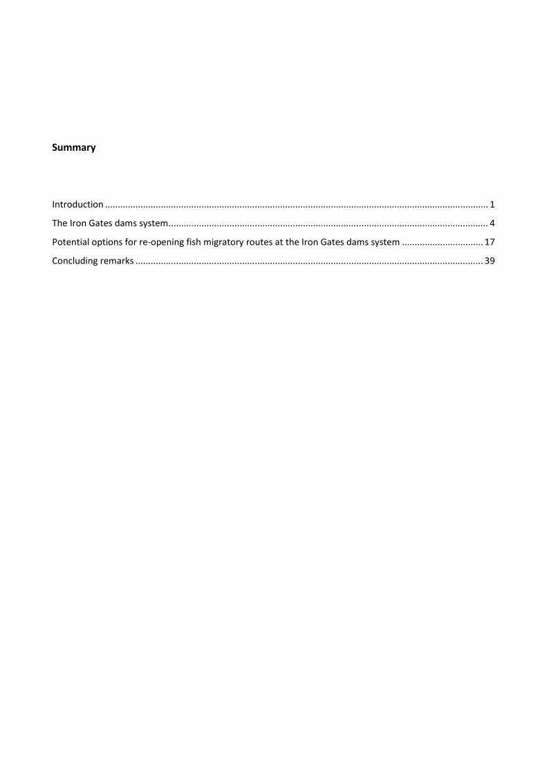
15
Fig. 17 View from left bank on the tailrace of the main HEP (picture O. Calles)
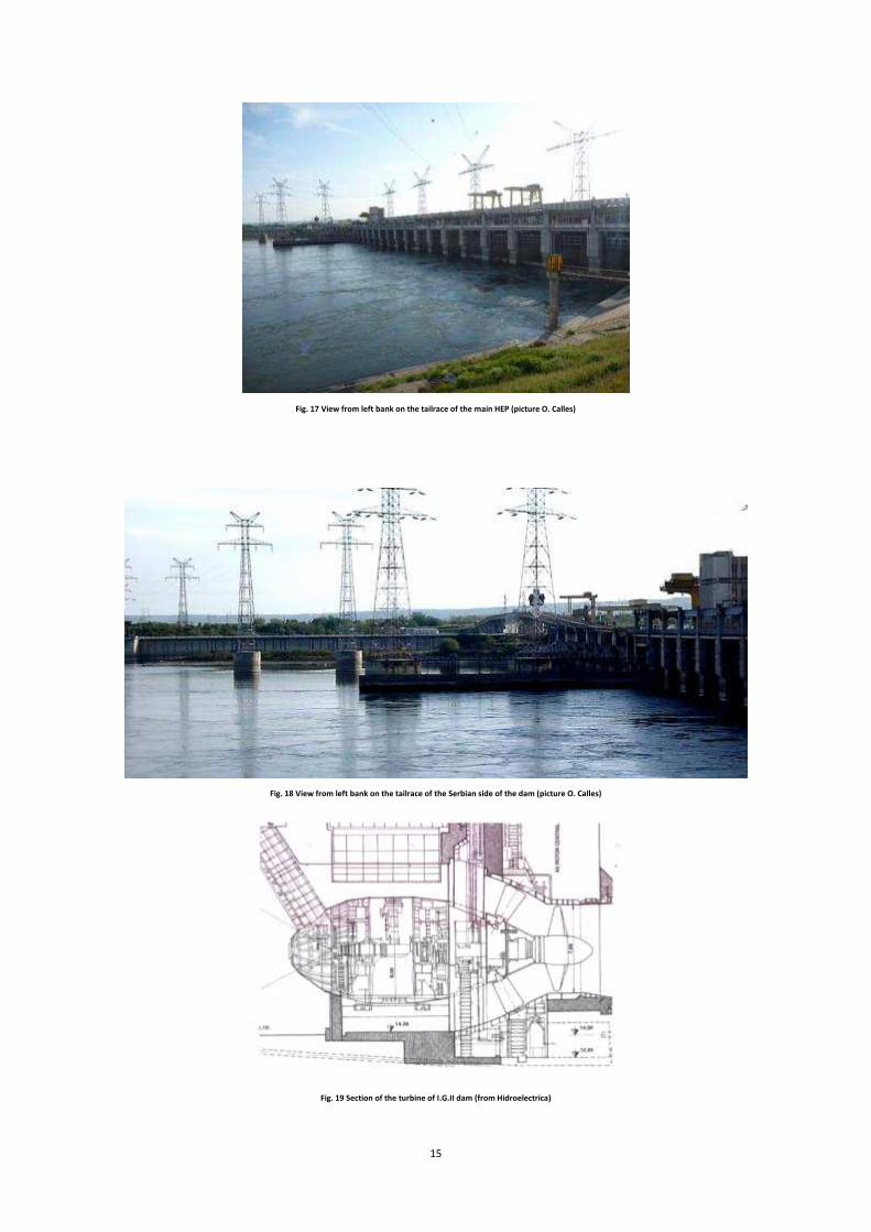
Fig. 18 View from left bank on the tailrace of the Serbian side of the dam (picture O. Calles)
Fig. 19 Section of the turbine of I.G.II dam (from Hidroelectrica)

The Iron Gates II system is operated according to the following general rules in relation to the Danube
discharge, using as a threshold the maximum discharge of the 20 units
the upper dam and 8 at the lower one; 10 in Serbia: 8 units adjacent to the 8 Romanian, and 2 at the right
bank of the lower dam).
If the Danube discharge is lower than that value (9,500 m³/s in the refurbished asset), it is split between the
two countries and passed through the tur
malfunctioning). At higher values the
until the Gogoșu branch reaches a total flow of 3,500 m³/s (i.e. 950 m³/s turbined +
downstream). Afterwards, i.e. at a
dam is activated until a discharge value equal to the one of the Gogo
the main Danube branch. After that, the operation of the turbines is limited, and higher flow is allowed to
pass downstream.
16
Fig. 20 Section of the spillway of I.G.I dam (from Hidroelectrica)
The Iron Gates II system is operated according to the following general rules in relation to the Danube
discharge, using as a threshold the maximum discharge of the 20 units fully operating
lower one; 10 in Serbia: 8 units adjacent to the 8 Romanian, and 2 at the right
If the Danube discharge is lower than that value (9,500 m³/s in the refurbished asset), it is split between the
two countries and passed through the turbines (or through the spillways in case of units maintenance or
the discharge in excess is first spilled through the upper dam spillway,
u branch reaches a total flow of 3,500 m³/s (i.e. 950 m³/s turbined +
at a Danube discharge higher than 12,050 m³/s, the spillway on the lower
dam is activated until a discharge value equal to the one of the Gogoșu branch is released downstream in
that, the operation of the turbines is limited, and higher flow is allowed to
The Iron Gates II system is operated according to the following general rules in relation to the Danube
fully operating (10 in Romania: 2 at
lower one; 10 in Serbia: 8 units adjacent to the 8 Romanian, and 2 at the right
If the Danube discharge is lower than that value (9,500 m³/s in the refurbished asset), it is split between the
bines (or through the spillways in case of units maintenance or
first spilled through the upper dam spillway,
u branch reaches a total flow of 3,500 m³/s (i.e. 950 m³/s turbined + 2,550 m³/s spilled
the spillway on the lower
u branch is released downstream in
that, the operation of the turbines is limited, and higher flow is allowed to

17
POTENTIAL OPTIONS FOR RE-OPENING FISH MIGRATORY ROUTES AT THE IRON GATES DAMS SYSTEM The affected fish species
In the following table (Tab.1) the main fish species affected by the presence of the Iron Gates dams,
according to the state-of-the-art knowledge of local ichthyologists of Romania and Serbia, and their general
conservation status (IUCN 2010) and inclusion in Habitat Directive (EC Dir. 92/43/EEC) are listed.
Table 1. MIGRATORY FISH SPECIES AFFECTED BY IRON GATES I/II
Species IUCN RED LIST Conservation status Habitat Directive Asp Aspius aspius Least concern Annex II, V Barbel Barbus barbus Least concern Beluga Huso huso CRITICALLY ENDANGERED Burbot Lota lota Least concern Carp Cyprinus carpio Vulnerable Ziege Pelecus cultratus Least concern Annex II, V Eel Anguilla anguilla CRITICALLY ENDANGERED Wels catfish Silurus glanis Least concern Ide Leuciscus idus Least concern Nase Chondrostoma nasus Least concern Pike-perch Sander lucioperca Least concern Pontic shad Alosa pontica (immaculata) Vulnerable Annex II, V Russian sturgeon Acipenser guldenstaedtii CRITICALLY ENDANGERED Stellate sturgeon Acipenser stellatus CRITICALLY ENDANGERED Sterlet Acipenser ruthenus Vulnerable Vimba bream Vibma vimba Least concern Volga pikeperch Sander volgensis Least concern Zingel Zingel zingel Least concern Annex II, V Other…
It is evident the relevance of species belonging to the Acipenseridae family; nevertheless the needs of many
migratory fish species have to be taken into account while considering the provision for free passage
through the Iron Gates dams.
The Iron Gates system affects migrations of anadromous, catadromuos and potamodromous species.
Migration periods vary according to the different species and mainly cover the months from October to July
for the upstream migration and from September to November for the downstream one. In any case it
would be ideal to guarantee proper functioning of the fish passes during all year.
Total lengths of upstream migrants vary from 10-20 cm for some Cyprinids to more than 320 cm for Beluga.
Further information is being collected by the local experts (e.g. further species, dimensions of migrants,
type of swimming, etc.) and more detailed data will be needed for the next project phase when fish pass
design will have to be carried out.

18
General preliminary comments
River connectivity must be restored throughout the whole Iron Gates system and therefore fish pass will
have to be designed at each of the obstacles (I.G. I and I.G. II).
Considering the significant width of the river, more than one fish passage facility will have to be provided at
each site.
Since connectivity is a two-way street, downstream migration issues will also have to be adequately
addressed.
During the mission several options were considered regarding the scope and extent of the possible FAO TCP
project; finally, the following stepwise approach has been agreed:
A. Developing fish passage design proposals for one fish pass at each of the Iron Gates dams (so that one full passage shall be provided through the system) by critically analyzing: - existing literature on sturgeon migration and passage (including other migratory species of the
Danube river present or potentially present at the sites); - local hydraulic conditions (water levels, flow velocities, direct measurements with acoustic
Doppler current profiler-ADCP, etc.) at different discharges and operating conditions to decide on the best possible design and location of the entrances;
- sturgeon behavior in approaching the structures during upstream migration (by means of telemetry techniques and observations with Didson camera, including other species).
The resulting design plans for these two fish passes will have to be easily translated, in a following stage, into construction plans by Serbian/Romanian engineering companies.
B. Critically analyzing the possibilities of operating the navigation locks for fish passage including - needs for modifications of the hydraulic conditions - sturgeon behavior as they approach the locks.
C. Proposing a preliminary routing and design of the other fish passage facilities. Once the first two fish passes will have been constructed as a follow-up to the FAO TCP, they will be monitored, and these monitoring results will be used by the Serbian and Romanian scientists to further improve, if necessary, the design of the other passes.
D. Proposing a preliminary routing and design of downstream passages.
In the following paragraphs initial proposals for possible technical solutions for fish passage at the dams are
briefly described, starting from I.G.II (in the view of upstream migrants).

19
Preliminary proposals for Iron Gates II lower dam
One of the main issues arising from the preliminary survey of the sites is the need for identifying the routes
preferred by fish when migrating upstream. A detailed analysis of the flow data recorded at the upper and
lower I.G.II dams (including operation of the fish lock at the channel through Ostrovul Mare island) will
therefore be fundamental, as well as a telemetry study aimed at investigating the routes chosen and the
precise sites below the I.G.II structures where fish tend to congregate during upstream migration.
According to available information regarding the operational rules established for the management of the
I.G. II system, the resulting scenario is the following (when all turbines are operated):
Table 2. DISCHARGES AT IRON GATES II BRANCHES Danube discharge Main branch Gogoșu branch (% of total Q)
Up to 9,500 m³/s Up to 8,550 m³/s
turbined Up to 950 m³/s (10%)
turbined
From 9,500 m³/s to 12,050 m³/s 8,550 m³/s
turbined Increases up to 3,500 m³/s turbined &
spilled (29%)
From 12,050 m³/s to 14,600 m³/s Up to 11,100 m³/s turbined & spilled
3,500 m³/s turbined & spilled (24%)
Considering that sturgeon upstream migration is usually expected at high discharges, the attractivity of the
Gogoșu branch should be adequately investigated (and very likely fish passage devices will have to be
provided there) even if the main flow still remains higher in the main stem (I.G.II lower dam), since the
activation of spillways raises the discharge through this secondary branch up to one third of the total. A
statistical analysis of discharges duration will supply further elements to the study.
Operation of the fish lock shall also be considered in order to evaluate to what extent its discharges can be
detected by fish moving upstream along the Gogoșu branch, even if discontinuous operation and limited
number of ships passed daily could represent a limiting factor for the choice of this route by upstream
migrants.
In any case priority should be given to the lower dam.
The flow downstream the dam is split between the main HEP (8+8 units) on the left bank and the small HEP
(2 units) on the Serbian bank.
Under the assumption of all the 18 units refurbished and in operation, the discharges flowing downstream
the I.G.II lower dam is as follows (percentages of the total flow through each way are highlighted):
Table 3. DISCHARGES AT IRON GATES II LOWER DAM Total Danube discharge Main HEP Small HEP Spillway
Up to 9,500 m³/s Up to 7,600 m³/s (88,9%) Up to 950 m³/s (11,1%) - From 9,500 m³/s to 12,050 m³/s 7,600 m³/s (88,9%) 950 m³/s (11,1%) -
From 12,050 m³/s to 14,600 m³/s 7,600 m³/s (68,5%) 950 m³/s (8,6%) Up to 2,550 m³/s (22,9%)
The main HEP on the left bank, even during high discharges, clearly represents the main flow which can be
detected by upstream migrants and therefore the first fish pass will have to be located at that site.

20
The total drop to be overcome by fish varies from 5.5 m (high flow conditions) to 11.8 m (low flow
conditions). The water levels in the reservoir range from 41.00 m a.s.l. (normal conditions) to 39.40 m a.s.l.
(higher flows) with a 1.60 m variation. The water levels in the tailrace have an higher range of variation
equal to 4.7 m (from 29.20 m a.s.l. during low flows up to 33.90 m a.s.l. at higher flows). A maximum drop
of 12.0 m and a minimum of 2.5 m are recorded.
As a general rule the first option to be considered (apart from dam removal) for re-establishing connectivity
for fish migration is the provision for a close-to-nature type of fish pass, and in particular a so-called
“bypass channel” which could bypass the obstacle in the form of a natural-looking channel that mimics a
natural
river, providing at the same time available habitat for aquatic fauna.
Fig. 21 Example of bypass channel (from DVWK, 2002)
The main limitation of this type of fish pass is the need for a relatively large surface area, since its slope
usually has to be around 1%, with mean flow velocities around 0.4-0.6 m/s. Short reaches with higher
slope, however within a maximum slope of 5%, can be incorporated in its path, e.g. mimicking the
mesohabitats variations (pool, rapids, etc.) that can be found in small pristine streams and tributaries in the
area. Boulders can also be included along the bypass channel, arranging them in a way that could keep
proper depth values and create suitable resting areas.
The issue of water levels variations upstream and in the tailrace (1.6 m and 4.7 m respectively) needs to be
addressed by inserting in the two extremes of the bypass channel technical sections in the form of several
pools connected by vertical slots.

21
Fig. 22 Example of paired vertical slot fish pass (from DVWK, 2002)
In any case, since the maximum drop to be overcome at the I.G.II dams is 12 m, the total length to be
considered for the fish pass is around 1.2 km (as maximum value, since the provision for steeper reaches
along the path could limit the total length to 0.8-1 km).
The fish entrance, i.e. the lower part of the fish pass, needs to be located approximately at the most
upstream point reachable by fish, avoiding high turbulence and recirculation areas.
Direct investigations below the dam by means of a telemetry study and the use of Didson camera will
provide fundamental input for a correct location of the entrance of the device for upstream moving fish.
According to the above considerations a preliminary solution (Fish Pass A) can be identified along the left
bank, on the left side of the HEP, profiting of the available space at that location. A possible path is outlined
in Figure 23. Potential interferences with roads, pipelines and underground structures and other
infrastructures will have to be adequately evaluated providing specific input for the for the final design.
Fig. 23 Possible path of a bypass channel on the left bank – Fish Pass A (from Google Maps)
The first part of the fish pass will have to be a technical one and shall be located along the river bank and
then turn into the Ostrovul Mare island in the wide space available in the green areas. For this purpose a

22
possible reference to be considered will be the recently built double-slot pool-pass on the Elbe River,
Germany (http://www.vattenfall.de/de/fischtreppe-geesthacht.htm) dimensioned in such a way that big
returning adult sturgeon are expected to pass, i.e. the pools are 16 m wide, 9 m long, 1.75 m deep, with
drop between pools of 0.10 m.
Fig. 24 Rendering of the Elbe River sturgeon fish pass (from Vattenfall, 2010)
Recommended minimum pool dimensions for sturgeon found in literature (DVWK, 2002) outline length of
5-6 m, width of 2.5-3 m, depth of 1.5-2 m and slot width of 0.6 m and a maximum drop between pools of
0.2 m.
The range of variation of water levels (4.7 m) in the tailrace will have to be adequately managed by
evaluating a proper location of the initial part of the bypass as, for instance, outlined in the next scheme.
Fig. 25 Two possible paths of the downstream section of the bypass channel – F.P. A (picture O. Calles)

23
Fig. 26 View on the left bank, with a possible path – F.P. A (picture O. Calles)
Fig. 27 Bypass channel at Harkort dam on river Ruhr, Germany (from Gebler, 2007)
Discharge at the entrance of the fish pass should be approximately 1 to 5 % of the competing flow of the
river during the migration period. In this case, considering the maximum discharge of the HEP (7,600 m³/s),
the fish pass should have a flow between 76 and 380 m³/s. Only a limited fraction needs to be allowed
through the fish pass (e.g. 5-10 m³/s) which will limit the size and the cost of the facility; the remaining
discharge (auxiliary flow) can be supplied from the forebay through one or more pipes equipped with a
turbine. This solution will allow to introduce the attraction discharge at different levels (accomplishing in

24
this way the variations in the tailrace water levels) at low velocity with limited aeration and turbulence and,
furthermore, will at least partially recover the losses due to discharges not passing through the existing
HEP. Their intake could even be located close to the upstream exit of the fish pass (thus providing adequate
devices for preventing fish to be directed towards the turbine) so that the total flow withdrawn from the
reservoir will be better perceived by downstream migrating fish as a proper route for bypassing the dam.
Because of the width of the river and the expected migration of sturgeons during high flow conditions a
second fish pass (Fish Pass B) should be provided close to the spillway, as outlined in the following scheme:
Fig. 28 Conceptual scheme (from Larinier, 2002)
In theory this second fish pass could be located on the right side of the spillway, exploiting the available
space between the spillway and the navigation lock which seems available both upstream and downstream
the dam (Figure 30). Since this part of the dam could not be surveyed during this scoping mission this
proposed option will have to be further investigated. In this case the typology to be used is a technical one
(vertical slot fish pass) with a folded path, a lower discharge and, if needed, a slightly higher slope, which
should allow to limit the size of the device, thus its length still remains significant.
It has to be outlined that turbine and spillway operations could be adjusted in order to improve the
attraction of the fish pass entrance. This would require to re-define the rules of operation of the turbines or
spillway gates (i.e. to define which turbines that need to be in operation according to different river
discharges) so that the turbulence created by the release at a specific location diverts fish towards the fish
pass entrance. This approach is clarified in the next Figure. Through this operational management scheme
of the HEP turbines and/or spillway gates, the entity of the attraction flow could be slightly lowered.

25
Fig. 29 Conceptual scheme of operating spillway gates (or turbines) to increase fish pass entrance attractivity (from Larinier, 2002)
A possible alternative solution could be the installation of a fish lift at the right side of the spillway (the
location will have to be chosen limiting interferences with the existing structures, especially during flood
events) or even between the spillway and the HEP (better location in terms of flow, i.e. attraction even
when the spillway is not active, but higher interferences with existing structures and, very likely, higher
construction costs). Considering the expected presence of shad, the device will have to be a lift with
crowder, with auxiliary flow to create proper attraction even at different tailwater levels.
Such a solution (fish lift) could even be taken into consideration when looking at other possible options for
the left bank (i.e. left side of the HEP, close to the bank).
Finally a third fish pass (Fish Pass C) shall be provided on the right bank (Serbia) where the smaller HEP is
located. According to the wide space that seems to be available, a bypass channel with initial and final parts
in the form of vertical slot fish pass, analogous to the one proposed on the left bank, seems to be the more
suitable option. Its path should be defined limiting any potential interference with existing infrastructures
located on that bank.

26
Fig. 30 Possible location of a technical fish pass and/or fish lift – F.P. B, and a bypass channel on the Serbian bank – F.P. C (from Google Maps)
Another option to be investigated is the possible use of the navigation lock for fish passage. Though
upstream passage of migrating fish by means of these devices is usually accidental and unintended
(because of their usual location in relatively calm zones which determines a limited attractivity for fish),
some adaptation works could improve this potential route. This could be achieved through the creation of
an adequate attraction flow downstream the lock by opening the filling sluices (partially or fully) with the
downstream gates also held open. Recent experiences in this field carried out by Companie Nationale du
Rhone on behalf of FAO could give a relevant contribution in the evaluation of this option. There should be
no significant interferences with the use of the lock for navigation since the operation of the sluice as fish
passage facility can be timed in such a way that ship traffic is not hampered.
In any case, at this stage, it can be stated that the option F.P. A for upstream passage seems to be the most
suitable out of the ones proposed so far.
With regards to downstream migration further detailed information still have to be collected in order to be
able to delineate an initial option: among these information, migratory species involved and timing of
migration, dimensions of migrants and type of swimming (surface, bottom, in shoals, nocturnal/diurnal,
etc.), details of turbines (for evaluating theoretical mortality rates) and trash-racks.
At this stage, considering the evidence gathered by Dr. R. Suciu by means of acoustic telemetry on sturgeon
downstream migration, which occurs at the surface along the main flow, a possible option could be
identified in the provision for surface guide walls in the forebay of the HEPs (Figure 31), aimed at

27
addressing downstream moving fish towards surface bypasses (Figure 32) to be built at the side(s) of the
HEP.
The guide wall should extend from the surface to a certain depth, so that fish migrating in the upper part of
the water column are deflected towards a surface bypass channel which leads them in the tailrace.
Fig. 31 Example of surface guide wall leading fish towards a downstream bypass (from Larinier, 2002)
Fig. 32 Conceptual scheme for location of downstream bypasses (from Larinier, 2002)
The limited variations of water levels in the reservoir could allow such a solution at the I.G. II dams.
At the same time other options could be investigated, such as the modification of trashracks spacings
(reduction) and inclination on the vertical in the view of providing a surface collection channel on the top of
the turbines intake as illustrated in Figure 33.

28
Fig. 33 Conceptual schemes for collection channels leading to downstream bypass (from Larinier, 2002)
A theoretical possible setup for the main HEP, in case of construction of a surface guide wall, could be the
following one (Figure 34), where the device would lead fish towards a downstream bypass to be located
between the HEP and the spillway. With the proposed position its upstream part could even provide some
guidance for locating the entrance of the bypass channel on the left bank.
Fig. 34 Possible location of a surface guide wall and downstream bypass at the main HEP (from Google Maps)
The guidance device could be even located in the opposite way, i.e. diverting fish towards the left side of
the HEP; in this case the downstream bypass could empty close to the upstream bypass channel entrance,
increasing its attractivity.

29
On the right side of the HEP open spillway gates, when active, could already represent a suitable path for
downstream migration that will have to be properly evaluated.
At the smaller HEP, in theory, a surface guide wall could be built further upstream the turbines intake
guiding fish towards the navigation lock (whose operation is however limited to few times per day) or
towards the upstream exit of the bypass channel on the right bank.
A simpler option could probably be the construction of a surface bypass at one or at each side of the HEP,
evaluating the possibility of providing a collection channel above the turbines intake. Variations in water
levels could be faced using adjustable sills and ramps leading towards surface oriented entrance(s).
Fig. 35 Possible location of surface guide walls and downstream bypass at the smaller HEP (from Google Maps)
An important issue to be considered will be the discharge to be allocated to the surface bypasses, that
should be from 2 to 10% of the HEP turbined discharges. A potential option could be to locate in the same
site the intake of the mini-HEP for increased attraction to the upstream fish pass and the downstream
bypass (preventing fish to enter in the intake of the mini-HEP).
The current exploitation of the spillways by downstream migrating species as a route for downstream
passage should be adequately investigated through telemetry studies as well as the current mortality rates
due to the installed turbines (more detailed data will have to be gathered in order to run appropriate
models aimed at estimating such values).
Furthermore, it is clear that the potential options proposed here do not address the needs of species
migrating at the bottom of the river (e.g. eels) and that specific detailed research (i.e. telemetry studies of
downstream migration of different fish species at the dam) is still needed before proposing other possible
detailed solutions (e.g. bottom bypasses, ramps leading to surface bypass, etc.).
30
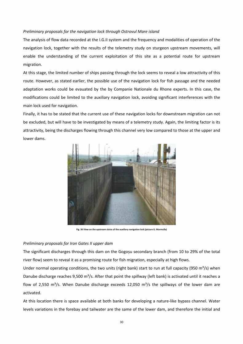
Preliminary proposals for the navigation lock through Ostrovul Mare island
The analysis of flow data recorded at the I.G.II system and the frequency and modalities of operation of the
navigation lock, together with the results of the telemetry study on sturgeon upstream movements, will
enable the understanding of the current exploitation of this site as a potential route for upstream
migration.
At this stage, the limited number of ships passing through the lock seems to reveal a low attractivity of this
route. However, as stated earlier, the possible use of the navigation lock for fish passage and the needed
adaptation works could be evauated by the by Companie Nationale du Rhone experts. In this case, the
modifications could be limited to the auxiliary navigation lock, avoiding significant interferences with the
main lock used for navigation.
Finally, it has to be stated that the current use of these navigation locks for downstream migration can not
be excluded, but will have to be investigated by means of a telemetry study. Again, the limiting factor is its
attractivity, being the discharges flowing through this channel very low compared to those at the upper and
lower dams.
Fig. 36 View on the upstream sluice of the auxiliary navigation lock (picture G. Marmulla)
Preliminary proposals for Iron Gates II upper dam
The significant discharges through this dam on the Gogoșu secondary branch (from 10 to 29% of the total
river flow) seem to reveal it as a promising route for fish migration, especially at high flows.
Under normal operating conditions, the two units (right bank) start to run at full capacity (950 m³/s) when
Danube discharge reaches 9,500 m³/s. After that point the spillway (left bank) is activated until it reaches a
flow of 2,550 m³/s. When Danube discharge exceeds 12,050 m³/s the spillways of the lower dam are
activated.
At this location there is space available at both banks for developing a nature-like bypass channel. Water
levels variations in the forebay and tailwater are the same of the lower dam, and therefore the initial and

31
final parts of the bypass will have to be constructed as a technical fish pass (vertical slot). At the same time,
dimensions of the devices can be similar to the ones proposed for the lower dam (i.e. average slope of 1%,
total length around 1,2 km).
Two bypass channels will have to be built, one at each bank. The constant flow of the HEP (when in normal
operation) would guarantee full attractivity for the bypass located on the right bank (Fish Pass D) when the
spillway is not active, while during high flows the bypass on the left bank (fish pass E) should operate at its
maximum efficiency.
Fish pass entrances (i.e. downstream part) should be located at the most upstream point that can be
reached by migrating fish, avoiding highly turbulent areas and recirculation zones. Possible routes are
outlined in the Figure 37, thus keeping in mind that the final path shall be chosen minimizing the
interferences with existing infrastructures.
Fig. 37 Possible paths of the upstream bypass channels at the Iron Gates II upper dam (from Google Maps)
Fig. 38 View on the right bank downstream HEP – F.P. D (picture O. Calles)

32
Discharge at the entrance of the bypasses should be approximately 1 to 5 % of the competing flow.
If bypasses are considered separately, the one on the right bank shall have an attraction flow of around 9.5
to 45 m³/s, while the one on the spillway side a flow of around 25.5 to 127.5 m³/s. An equal dimensioning
at a discharge of 30 m³/s each could seem to be appropriate.
Another option could be the operation of the bypass on the left bank only during high flows; in this case it
could be worthwhile to build it completely as a technical fish pass, since it would not be used by aquatic
fauna as a permanent habitat.
Again, in order to limit the size and the cost of the facilities, only a limited fraction of the attraction flow
can be allowed through the fish passes (e.g. 5-10 m³/s), and the remaining discharge (auxiliary flow) can be
supplied from the forebay through small turbines, introducing the attraction discharge at different levels
(accomplishing in this way the variations in the tailrace water levels).
With regards to downstream migration, bypasses and guiding devices could be provided in order to safely
address migrating fish towards the tailrace. The same concepts and limitations highlighted for the lower
dam apply here.
A possible setup is illustrated in the next Figure. A surface guide wall could be placed upstream the HEP,
diverting fish towards the spillway, which could be used during high flows for downstream passage; this
guide wall could also address fish towards the upstream part of the bypass channel on the right bank
(F.P.D). If the spillway will not be evaluated as a safe path for downstream migration, another surface guide
wall could be placed upstream the spillway addressing fish towards a downstream bypass located on the
left bank, close to the entrance of the upstream fish pass (creating further attraction for F.P.E). Eventually a
collection channel could be built above the HEP turbines intake to lead fish towards downstream bypass(es)
located at the side(s) of the HEP itself.
However all these options, and many more which could be identified in a later stage of the study, will have
to be adequately analyzed after having gathered sufficient information, now incomplete or missing, on
downstream migration features at the dam.

33
Fig. 39 Possible paths of the downstream migration devices (from Google Maps)
Preliminary proposals for Iron Gates I
The total discharge of the Danube river (in normal operating conditions) flows through the two HEPs until a
value of 10,080 m³/s; after this threshold the spillways are activated by both countries in an almost equal
way. Upstream water levels variations range from 63.00 to 69.59 m a.s.l. (6.59 m = maximum variation),
while downstream from 43.50 m a.s.l. (during high flows) down to 41.50 m a.s.l. (2 m variation). The
resulting total drop to be considered for the fish pass design varies from 19.5 m (high flow conditions) to
28.09 m (low flow conditions).
Even in this case the optimal solution for providing upstream passage will be to consider a nature-like
bypass channel (Fish Pass F). According to the maximum total drop this solution would require a maximum
length of around 2.8 km (i.e. 1% slope); however, as stated earlier, this length can be reduced by providing
a series of steeper reaches along the bypass, thus keeping hydraulic conditions suitable for fish migration,
limiting this value to 1.7-1.8 km. Through the survey on both banks, only the Serbian one is characterized
by a significant space available for developing such a long route (interferences with surface and
underground infrastructure will have to be adequately analyzed). As outlined for the I.G. II dams the
upstream and downstream portions of the bypass will have to be built in form of technical pass (vertical
slot) to accomplish the significant water levels variations (especially those of the reservoir). Very likely
multiple exits shall be designed for the upstream portion of the fish pass.
The entrance to the bypass channel (i.e. downstream section) should be located at the upstream point
reachable by migrating fish, but at this site the presence of the navigation lock represents an obstacle. In
34
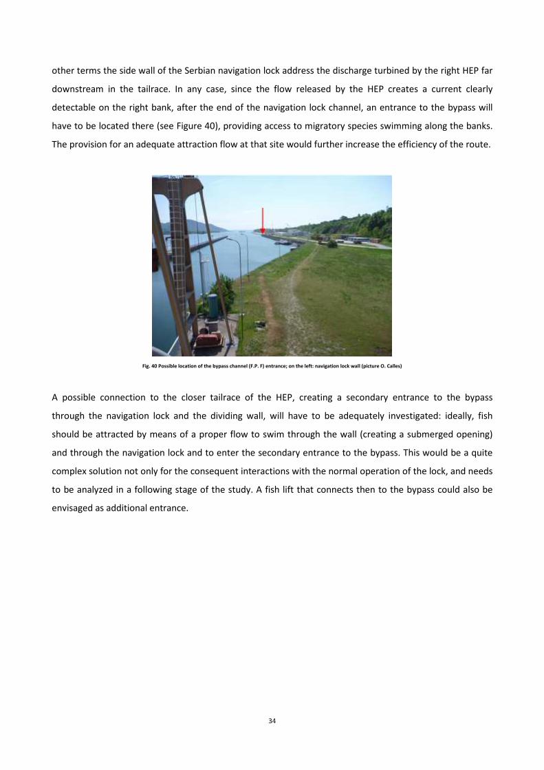
other terms the side wall of the Serbian navigation lock address the discharge turbined by the right HEP far
downstream in the tailrace. In any case, since the flow released by the HEP creates a current clearly
detectable on the right bank, after the end of the navigation lock channel, an entrance to the bypass will
have to be located there (see Figure 40), providing access to migratory species swimming along the banks.
The provision for an adequate attraction flow at that site would further increase the efficiency of the route.
Fig. 40 Possible location of the bypass channel (F.P. F) entrance; on the left: navigation lock wall (picture O. Calles)
A possible connection to the closer tailrace of the HEP, creating a secondary entrance to the bypass
through the navigation lock and the dividing wall, will have to be adequately investigated: ideally, fish
should be attracted by means of a proper flow to swim through the wall (creating a submerged opening)
and through the navigation lock and to enter the secondary entrance to the bypass. This would be a quite
complex solution not only for the consequent interactions with the normal operation of the lock, and needs
to be analyzed in a following stage of the study. A fish lift that connects then to the bypass could also be
envisaged as additional entrance.

35
Fig. 41 Possible connection through the navigation lock (picture O. Calles)
This potential limitation of the proposed solution (entrance far downstream the HEP) could be overcome by
providing an alternative route by means of the installation of a fish lift at one side of the HEP, so that fish
congregating just below the turbines would more easily find a way for upstream passage.
In this case the limited variations of the downstream water levels would allow an easier operation of such a
device, which could be located or on the right bank, along the navigation lock wall, or between the HEP and
the spillway. Interactions with existing infrastructures will have to be adequately analyzed with particular
regard to flood events. The same issue (interactions with existing structures) will apply when designing the
connection to the upstream reservoir, where collected fish will have to be released. In theory a connection
to the bypass on the right bank, crossing the navigation lock, could be considered as an option.
On the Romanian bank (left bank) space availability is limited, but nevertheless it could be possible to draw
a path for a technical fish pass (vertical slot), folded several times, and with a limited discharge and an a
slightly higher mean slope, which could connect the lower tailrace (after the navigation lock wall) to the
upstream reservoir (Fish Pass G).

36
Fig. 42 Space available on the left bank, downstream the dam (picture G. Marmulla)
Again at this location a fish lift could be installed at one side of the HEP, as outlined in Figure 43.
As far as discharges are concerned, considering the 1-5% rule, each fish pass should have an attraction flow
from 54 to 270 m³/s. Due to these high discharge values it will be necessary to provide adequate auxiliary
flow through pipes and small turbines, limiting the fish pass dimensions. This additional flow will have to be
introduced at different levels, so that attraction will be guaranteed along the whole range of downstream
levels variations.
The nature-like bypass channel on the Serbian bank could, on the other hand, be even designed for
discharges higher than 10 m³/s.
Finally, even for I.G. I dam the possible use of the navigation lock for fish passage and the needed
adaptation works will have to be taken into proper consideration.

37
Fig. 43 Possible locations of fish passes at the Iron Gates I dam (from Google Maps)
With regards to downstream migrations the main options suggested for I.G.II can also be proposed here.
Surface guidance devices upstream each HEP and downstream bypasses at their inner side(s) seem to be an
option to be taken into account; in this case, higher upstream water levels fluctuations will affect the
surface guide walls design.
Even in this case the current use of spillways and navigation locks will have to be investigated before the
design phase. As clearly outlined earlier, detailed studies on downstream migration features are required.

38
Fig. 44 Possible location of surface guide walls and downstream bypasses (from Google Maps)

39
CONCLUDING REMARKS
The scoping mission highlighted that the provision for migration routes at the Iron Gates dams is technically
feasible. As discussed earlier several challenging issues will have to be faced when carrying out the
preliminary design phase and detailed input data will have to be gathered from existing databases and
monitoring systems (dam managers) and through direct observations (e.g. ADCP measurements
downstream the HEPs). The most critical issue will be the choice of the right location of the upstream fish
passes entrance: a specific telemetry study on sturgeon is absolutely needed (direct involvement of Dr.
Suciu and Lenhardt is required) and it will have to be carried out in close cooperation with the TCP design
team.
Nevertheless the focus shall not be devoted only to sturgeon, but to all migratory species which are now
affected in their life-cycle by these obstacles. A proposal for the TCP title would therefore be “Reopening
migration routes of sturgeons and other migratory fish through the Iron Gate dams”. The expected
outcomes will be the design plans of one fish pass at I.G.I and one at I.G.II (Fish Pass A and F currently seem
the most appropriate), which will have to be easily translated, in a following stage, into construction plans
by Serbian/Romanian engineering companies. Preliminary designs of other options will also be provided,
together with input for downstream migration devices (however this last issue will require further studies
on involved fish species and related behavior).