scoppg ying study to evaluate two rig tests for … dpg dp-04 rig... · two rig tests for internal...
TRANSCRIPT

CRC Project DP 04CRC Project DP-04
Scoping Study to Evaluate p g yTwo Rig Tests for Internal Injector Sticking
July 2012
COORDINATING RESEARCH COUNCIL INC3650 MANSELL ROADSUITE 140ALPHARETTA GA 30022
The Coordinating Research Council Inc (CRC) is a non-profitcorporation supported by the petroleum and automotive equipmentindustries CRC operates through the committees made up of technicalexperts from industry and government who voluntarily participate Thefour main areas of research within CRC are air pollution (atmosphericfour main areas of research within CRC are air pollution (atmosphericand engineering studies) aviation fuels lubricants and equipmentperformance heavy-duty vehicle fuels lubricants and equipmentperformance (eg diesel trucks) and light-duty vehicle fuels lubricantsand equipment performance (eg passenger cars) CRCrsquos function is topro ide the mechanism for joint research cond cted b the t oprovide the mechanism for joint research conducted by the twoindustries that will help in determining the optimum combination ofpetroleum products and automotive equipment CRCrsquos work is limitedto research that is mutually beneficial to the two industries involvedand all information is available to the public
CRC makes no warranty expressed or implied on the application ofinformation contained in this report In formulating and approvingreports the appropriate committee of the Coordinating ResearchCouncil Inc has not investigated or considered patents which mayCouncil Inc has not investigated or considered patents which mayapply to the subject matter Prospective users of the report areresponsible for protecting themselves against liability for infringementof patents
2
CRC Diesel Performance GroupCRC Diesel Performance GroupDeposit Panel
Scoping Study to Evaluate Two Rig Tests for Internal Injector Sticking
CRC P j R DP 04CRC Project Report DP-04
July 2012
BenchRig Investigation Sub Panel Memberse c g est gat o Sub a e e be s
Hind Abi-AkarJoan AxelrodRodica BaranescuRick ChapmanMichael FosterAlex KulinowskiShailesh LopesManuch Nikanjam (leader)Manuch Nikanjam (leader)Jim Rutherford
4
Acknowledgementc o edge e t
Caterpillar Inc and Innospec devoted valuable test p pfacilities resources and expertise to carry out this program at no cost to CRC
5
Abstractbst act
Shortly after the formation of a Deposit Panel within the CRC Diesel Performance Group th EMA h d th P l d t d i iti ti f t ff t t l t ththe EMA approached the Panel and requested initiation of an urgent effort to evaluate the causes of a new internal injector deposit problem The panel diverted attention to this issue and formed three sub-panels
ndash Data Analysis and Recommendationyndash Bench Rig Engine Investigationndash Engine Investigation
The Bench Rig Engine Investigation Panel identified two potential rigs for evaluation This program which required no CRC funding was conducted to determine if any of these rigs would discriminate among known deposit forming and non deposit forming fuelsThis report provides a detail description of both rigs and the results obtained in each case using seven fuels in a statistically designed matrix Being an initial scoping study parameters such as additives biodiesel and impurities were not included
6
ObjectiveObject e
Identify or develop a laboratory bench top or test rig for y p y p gevaluating fuelrsquos tendency to cause internal injector deposits as well as additiversquos effectiveness to avoid such deposit formationssuch deposit formations
7
ScopeScope
This initial phase was a limited scoping and screening p p g gprogram using two in-house tests to determine if fuels which are expected to cause internal injector deposits can be differentiated from those that are not expected tocan be differentiated from those that are not expected to form such deposits
8
Not Included in This Studyot c uded s Study
Detail study ofyndash Impuritiesndash Additivesndash Biodiesel
9
Test FuelsE h F l W T t d T i i E h RiEach Fuel Was Tested Twice in Each Rig
Type Description Source Designation
EPA S15 Real world fuel from a region that has not had issues
The EMA EPANoDep
EPA S15 Real world fuel from a region that has had The EMA EPADepissues
CARB Typical California diesel assumed to have no issue
Chevron CARB
EPA S15 Formulated
Deposit forming formulated Afton Chemical RDep
EPA S15 Not deposit forming formulated Afton Chemical RNoDepFormulated
Old Fuel Higher sulfur from overseas Innospec HiSulf
Reference 93 35 ppm sulfur made to a recipe deposit Innospec R93pp p pforming
p
10
Fuel Analysisue a ys s
Specific gravity or densityp g y ySulfur levelDistillationMetals content by ICPThermal stabilityAsh contentNACE corrosion (TM0172)
An attempt was made to determine what types of additives if any exist in each fuel
11
Volunteer Fuel Analysis Laboratorieso u tee ue a ys s abo ato es
BP NapervillepChevronExxonMobil Research and Engineering
12
F l A l iFuel Analysis
Results
Sulfur LevelSu u e e
Different method used by each lab ndash D7039 D5453 D2622-1 14
Distillation ndash Initial Boiling Pointst at o t a o g o t
15
Distillation ndash 50 Recoveredst at o 50 eco e ed
16
Distillation ndash 90 Recoveredst at o 90 eco e ed
17
Distillation ndash End Pointst at o d o t
18
Ash Contents Co te t
Two labs reported ash (D482) one reported sulfated ash (D874) 19
NACE Corrosion ndash TM0172C Co os o 0
20
Densitye s ty
21One lab reported specific gravity (D1298) one lab reported API gravity (D4052) and one lab reported density and API gravity (D4052) All were converted to density
Thermal Stabilitye a Stab ty
22
Metal Content by ICPeta Co te t by C
23Metals were by ICP One lab used EN 14538 (IP 547) one lab used D5185 and one lab used proprietary ICP All were below detection limits
Metal Content by ICPeta Co te t by C
Metals were by ICP One lab used EN 14538 (IP 547) one lab used D5185 and one lab used proprietary ICP All were near or below detection limits
24
C t ill RiCaterpillar Rig
Caterpillarrsquos Deposit Bench TestCate p a s epos t e c est
Conceived by Caterpillar Inc circa 2006y pndash Patent pending
Simple and versatile setup that allows controlled t f f l d i t b bi d t l t damounts of fuel and air to be combined at an elevated
temperature and pressure over an experimental substrateIntended to replicate conditions that lead to deposit formation in engines and to form representative deposits in a short period of timedeposits in a short period of timeUsed to test both fuels and oilsConsidered a research toolConsidered a research tool
26
Use of the Deposit Bench Test at CaterpillarTest condition can be varied See ldquoTest Procedurerdquo
Example 1 Confirmed impact of fuel system cleaner ndash simulated field observations
Fuel Fuel + Deposit Forming Additive
Fuel + Deposit Forming
Fuel + Deposit Forming Additive
Fuel + Deposit Forming g g
Additive + Low Dose Cleaner
g Then High Dose
Cleaner
gAdditive Then
Low Dose Cleaner
27
Use of the Deposit Bench Test at CaterpillarUse o t e epos t e c est at Cate p a
Example 2 Studied impact of fuel additives on fuel deposit propensityndash Open Forum SAE Congress Detroit MI April 15 2010
28
Test Procedureest ocedu e
Typical operating conditions of the deposit bench testndash Pressure 1000 psigndash Temperature180 ndash 250degCndash Airfuel ratio 5 ndash 10 by volumendash Test fuel required 300 mL
Test duration 5 hrs
Deposits collected on the substrate (springs and rod) are considered representative of ldquostickyrdquo internal injector deposits or those that form on a metal surface in an enginendash Test duration 5 hrs
Parameters measuredndash Mass of deposit collected on test substrate
M f d it ll t d 40 d 7 filtndash Mass of deposit collected on 40 microm and 7 microm filtersbull Deposits dried in vacuum oven at ~125degC for 16 hrs before weighing
ndash In some cases analytical analysis of deposits filters and tested fuels was conductedbull FTIR TPO SEM EDS etc Filter deposits are considered representative of
test fluid oxidationCleaning between tests
ndash The setup is rinsed by circulating solventsbull Presently pentane then acetonebull Historically heptane
test fluid oxidation
ndash If necessary the entire system can be dismantled and cleaned with a brush and acetonebull All Swagelok fittings and tubing can be replaced at low cost
29
Deposit Bench Apparatusepos t e c ppa atus
40 microm 7 microm
30
Fuel FuelAir MixtureAir Location of Substrate (see inset) Inside Reactor
Test Procedureest ocedu e
A 300 mL test fuel sump can be heated and stirred as necessaryFuel (pink) passes through a 10 microm suction filter and is pumped and metered to 1000 psig at 5 mLminThe fuel is then heated to 180degC as it travels to the reactorPressurized air at 1000 psig (blue) at 180degC and 25 mLmin joins the fuel line tube-in-tube before entering the reactor Inside the reactor the deposit substrate (yellow) consists of two steel springs supported on a steel rod This substrate is weighedsteel springs supported on a steel rod This substrate is weighed before and after testing to measure deposit accumulation (Heat tape and insulation have been removed from the reactor for clarity)The oxidized airfuel mixture (orange) passes out of the reactorThe oxidized airfuel mixture (orange) passes out of the reactor through 40 microm and 7microm filters and finally through the back-pressure regulator Fuel returns to the sump at atmospheric pressure and is recirculated
31
CRC Test PlanC C est a
Test FuelsOld Fuel (HS) EPA S15
(Deposit Forming)
EPA S15 (Not Deposit Forming)
EPA S15 (Real World No Issues)
EPA S15 (Real World With Issues)
CARB Reference 93 (35 ppm S Deposit Forming)
P1102-2413-A R11001612 with NaOH
R11001595 Detroit John Deere D8233 P1011-7749-A
F els ere tested in three stages
with NaOH
P1102-2413-B R11001612 without NaOH
R11001595-B Detroit2 D8236 P1011-7749-B
Fuels were tested in three stagesndash Each stage of testing conducted by a different teamndash May be variation in test operation
bull Cleaning and setup proceduresg p pbull Air flow rates
It was observed that a fuel could ldquoflashrdquo during testing If this occurred large amounts of deposits resulted
ndash This may have happened without notice by the operator during early testing
32
C t ill RiCaterpillar Rig
Data Presentation and CommentsNote Due to timing and internal organization fuels were tested in three stages each by a different team
Deposit Results ndash Substrate Depositsepos t esu ts Subst ate epos ts
Many but not all of the results were repeatable
025
03Team 1 - Substrate Deposits
0 1
015
02
epos
it M
ass
(g)
0
005
01De
34
Deposit Results ndash Substrate Depositsepos t esu ts Subst ate epos ts
Adding NaOH did not cause deposits in all fuels
0025
003Team 2 amp 3 - Substrate Deposits
001
0015
002
epos
it M
ass
(g)
0
0005
001
De
N tNotes The John Deere fuel test was shut down prior to completion due to excessive deposits clogging the system
The Cat Reference-3 test occurred after known system contamination The difference between this measurement and the other Cat Reference measurements is likely due to insufficient system decontamination
35
Deposit Results ndash Filter Depositsepos t esu ts te epos ts
Obvious differences from the substrate deposits
0 14
016
018
02Team 1 - Filter Deposits
008
01
012
014
epos
it M
ass
(g)
0
002
004
006De
36
Deposit Results ndash Filter Depositsepos t esu ts te epos ts
0025
003
)
Teams 2 amp 3 - Filter Deposits
001
0015
002
epos
it M
ass
(g)
0
0005
0 0
D
NotesNotes The John Deere fuel test was shut down prior to completion due to excessive deposits clogging the system
The Cat Reference-3 test occurred after known system contamination The difference between this measurement and the other Cat Reference measurements is likely due to insufficient system decontamination
37
Caterpillar Observations and ConclusionsCate p a Obse at o s a d Co c us o s
Substrate deposit mass and filter deposit mass are the primary metrics of fuel deposit propensitydeposit propensityThe system is sensitive to changes in the operation details
ndash Demonstrated difficulty in data repeatabilitybull Some data was repeatable but not all
The system history can impact datandash Tests run after known system contamination seemed to have unusually high amounts of
deposits
In many cases the amount of deposits generated was small enough toIn many cases the amount of deposits generated was small enough to challenge the detection limit of the balance used
ndash Test conditions should be optimized to produce more measurable results and more differentiation
The test rig may better represent some types of deposits than othersThe test rig may better represent some types of deposits than othersndash Oxidation-driven deposits are the prime target of the rig
5-hour test time may not be optimum for all fuelsndash Different fuels may experience a different amount of degradation in 5 hours
38
CAT CATERPILLAR their respective logos ldquoCaterpillar Yellowrdquo the ldquoPower Edgerdquo trade dress as well as corporate and productidentity used herein are trademarks of Caterpillar and may not be used without permission
copy2012 Caterpillar All Rights Reserved
C t ill RiCaterpillar Rig
More Formal Data AnalysisNote Due to timing and internal organization fuels were tested in three stages each by a different team
All Data ndash Trellised by Teamata e sed by ea
T i d d i d iTest terminated due to excessive deposits
40
Teams 2 and 3 ndash Trellised by Teamea s a d 3 e sed by ea
Test terminated due to excessive deposits
41
All Data ndash Trellised by Teamata e sed by ea
Test terminated due to excessive deposits
42
Teams 2 and 3 ndash Trellised by Teamea s a d 3 e sed by ea
Test terminated due to excessive deposits
43
I RiInnospec Rig
Methodologyet odo ogy
Injector rig conditions used for the program
Variable Setting
Injectors 4 new Bosch CRIN1 injectors per runper run
Filters 2 new Fleetguard FF167 filters per run
Pre-rig clean Repeat rinses with MeOH MEPP (Methoxy Propoxy Propanol) and test diesel
Run time 100 hours
Cycle Standard rig test cycle
Injector tip temperature 180ordmC
Fuel tank temperature 35ordmC
Fuel volume 32 litres
RPM flywheel 1200
45
Analysisa ys s
The following tests were carried out to measure deposition rates
Component Test Measurement Testing Details
Filter Insoluble Carbon Total carbon from both filters by TPO (microgcm-2)
Performed in triplicate on both filters from runy ( g )
See next page for definition of TPO
Injector Back Leakage Change in performance from new injector
Performed in duplicate on each injector
Injector Pressure Drop Change in performance from new injector
5 tests on each injector
I j t I j t Ti D it N li d bl k t d T t f d ll 4Injector Injector Tip Deposit Normalized blank corrected carbon deposit level by TPO
Test performed on all 4 injectors from run
Injector Injector Needle Deposit
Injector Injector Push Rod Deposit
46
Temperature Programmed Oxidation (TPO)e pe atu e og a ed O dat o ( O)
Sample is placed in a quartz sample boat and inserted into a temperature-controlled furnace where it is heated in a calibrated oxygen atmosphere Oxygen feed rate = 0 75 liters perOxygen feed rate 075 liters per minuteStarting temperature = 270degC For testing the temperature was increased to 700degC at a rate of 100degC per minute The CO2 resulting from the oxidation of the carbon is detected by calibrated IR detectorsdetectors Total carbon result calculated from amount of CO2 ndash can either be expressed per unit area (if known) or e p essed pe u t a ea ( o ) onormalized to a surface area = 1
47
I RiInnospec Rig
Data Presentation and Comments
Analysis ndash Insoluble Filter Depositsa ys s so ub e te epos ts
Both fuel tank filters removed and dismantled5 x 1 cm vertical sections removed for analysis from each filterEach section placed in 60 mLEach section placed in 60 mL tri-solvent (602020 toluene acetonemethanol) and placed in an ultrasonic bath for 30 minutesSolvent then filtered through 07-micron GF filter paperFilter paper rinsed with 2 x 25 mL washes of isooctane and dried atwashes of isooctane and dried at 100degC for 2 hoursTest performed in triplicate on both filters
49
CRC Testing ndash Filter DepositsC C est g te epos ts
Each GF filter paper run on RC612 TPO analyzer
Run Fuel Average Total Carbon Deposit (microgcm2)analyzer
Sample was run under ramp method from 270degC to 700degCTotal carbon calculated per unit area of original fuel tank filter paper (10 cm2)
Deposit (microgcm )
1 RNoDep 10837
2 RDep 8837
3 EPANoDep 16650original fuel tank filter paper (10 cm )Results quoted as average total carbon for both filters
p
4 EPADep 10360
5 R93 8013
6 HiSulf 6650
ObservationsHi Sulf R93 and CARB gave lowest resultsIncreased filter deposits observed in Runs 3 and 14 following NaOH-treated runs
f 2 d 13 ti l i
7 CARB 7343
8 CARB 7380
9 HiSulf 8127
of 2 and 13 ndash suggesting cleaning process not removing all NaOH as second run with same fuel gave appreciably different resultsVery good repeatability achieved with the exception of runs that followed NaOH
10 R93 6550
11 EPADep 8350
12 EPANoDep 9323
13 RDep 67 53exception of runs that followed NaOH addition (3 and 14)
13 RDep 6753
14 RNoDep 7377
50
Injector Testingjecto est g
Each injector removed from rig and mounted in DIT31 Injector TesterEach injector measured pre- and post-test for
Back leakagendash Back leakagendash Pressure drop
Result quoted is differencebetween pre- and post-testbetween pre and post test
51
CRC Testing ndash Back LeakageC C est g ac ea age
Test performed in duplicate on each of all 4 injectors Run Fuel Average Change
(Pre- to Post-Test)Secondsall 4 injectorsResults quoted are the average change for all injectors from each runInjector is pressurised to 1100 barAir supply is switched off and the pressure
(Pre- to Post-Test)Seconds
1 RNoDep -563
2 RDep -508
3 EPANoDep 185allowed to return to ambientBack leakage is quoted as the time taken to fall from 600 to 200 barThe faster the time the greater the likelihood of injector seal failure
p
4 EPADep -250
5 R93 401
6 HiSulf -318likelihood of injector seal failure The higher the negative value the greater the loss of performance
Observations
7 CARB -659
8 CARB -099
9 HiSulf -408
High degree of variability between batches of same fuelDifficult to quantify significant changes in performanceNot recommended as a performance
10 R93 -323
11 EPADep -154
12 EPANoDep -248
13 RDep -4 55Not recommended as a performance measurement
13 RDep -455
14 RNoDep -098
52
CRC Testing ndash Pressure DropC C est g essu e op
Test performed 5 times on each of all 4 injectors Run Fuel Average Change
(Pre- to Post-Test)BarinjectorsResults quoted are the average change for all injectors from each runInjector is pressurised to 1100 barAir supply is switched off and the pressure
(Pre- to Post-Test)Bar
1 RNoDep 015
2 RDep 280
3 EPANoDep 455pp y pallowed to return to ambientAt 750 bar the injector is fired for 8 msThe pressure drop during firing is measured in barA i ifi t f ll i d f t t t
p
4 EPADep 245
5 R93 400
6 HiSulf 470A significant fall in pressure drop from start to finish is indicative of deposit buildupAn significant increase in pressure drop could be indicative of injectorlsquostickingrsquo
C l i (t d t )
7 CARB 145
8 CARB -213
9 HiSulf 387
Conclusions (to date)High degree of variability between batches of same fuelDifficult to quantify significant changes in performance
10 R93 1030
11 EPADep -205
12 EPANoDep 245
13 RDep 0 95performanceNot recommended as a performance measurement
13 RDep 095
14 RNoDep 735
53
Injector Dismantlingjecto s a t g
All 4 injectors from each run dismantled3 t t i d f l i3 parts retained for analysis
ndash Tipndash Needlendash Pushrod
Parts rinsed in toluene then acetone then dried in oven for 2 hoursTPO analysis performed on all 4 injectors from each run ndashfinal result is average of 4 testsFi l d it l l l l t d b i b l lFinal deposit level calculated by measuring carbon levels and subtracting blank injector resultTip and needle analysis too variable ndash did not differentiate between fuels
54
CRC Testing ndash Injector TipC C est g jecto p
Run Fuel Average Total Carbon Deposit (microgcm2)
Each tip sectioned using diamond saw to allow testing of tip section exposed in rig Deposit (microgcm2)
1 RNoDep -598
2 RDep 467
3 EPANoDep -533
allow testing of tip section exposed in rigSample run on RC612 TPO analyzer from 270degC to 700degCEach test was baseline corrected against a new pushrod p
4 EPADep -698
5 R93 15785
6 HiSulf 333
new pushrodResults are based on a fixed surface area of 1 cm2
Conclusions (to date)7 CARB 1763
8 CARB -073
9 HiSulf -367
Conclusions (to date)Excess variability in results ndash most likely to be due to washing effect in post-injector drain (C of V typically gt100)Difficult to draw any conclusions ndash analysis
10 R93 6068
11 EPADep 3973
12 EPANoDep -280
13 RDep 30 10
y ynot satisfactory in current form Variation in test resulted in some totals being less than blank needleNot recommended as a performance
d i d b 13 RDep 3010
14 RNoDep 3045
55
measurement ndash drain needs to be redesigned
CRC Testing ndash Injector NeedleC C est g jecto eed e
Each needle sectioned using diamond saw to allow testing of needle section with no Run Fuel Average Total Carbon
Deposit (microgcm2)to allow testing of needle section with no DLC coatingSample run on RC612 TPO analyser from 270degC to 700degCEach test was baseline corrected against a
Deposit (microgcm2)
1 RNoDep -010
2 RDep 163
3 EPANoDep 283Each test was baseline corrected against a new pushrodResults are based on a fixed surface area of 1 cm2
p
4 EPADep 030
5 R93 133
6 HiSulf -143
Conclusions (to date)Excess variability in results ndash most likely to be due to minute levels of deposit on section (C of V typically gt100)
7 CARB 885
8 CARB 367
9 HiSulf 510
Difficult to draw any conclusions ndash analysis not satisfactory in current form Variation in test resulted in some totals being less than blank needleNot recommended as performance
10 R93 1453
11 EPADep 1333
12 EPANoDep 133
13 RDep 13 15Not recommended as performance measurement
13 RDep 1315
14 RNoDep 1478
56
CRC Testing ndash Injector Push RodC C est g jecto us od
Each pushrod run on RC612 TPO analyzer from 270degC to 700degC Run Fuel Average Total Carbon
Deposit (microgcm2)from 270 C to 700 CEach test was baseline corrected against a new pushrodResults are based on a fixed surface area of 1 cm2
Deposit (microgcm2)
1 RNoDep 1620
2 RDep 1538
3 EPANoDep 1735p
4 EPADep 1103
5 R93 1187
6 HiSulf 900
ConclusionsAll fuels created deposits on the pushrodVery good repeatability achieved with the
7 CARB 1863
8 CARB 1590
9 HiSulf 1098Very good repeatability achieved with the exception of Runs 3 and 14 that followed NaOH addition Runs 2 and 13EPADep and HiSulf gave lowest resultsRNoDep gave highest results but this may be skewed by previous run
10 R93 1493
11 EPADep 1215
12 EPANoDep 1220
13 RDep 14 10be skewed by previous runTest appears to differentiate between fuels
13 RDep 1410
14 RNoDep 3548
57
Innospec Rig Summary ndash Prorsquosospec g Su a y o s
Two tests identified as showing differentiation between fuels with good repeatability
ndash Total insoluble carbon from post-tank filtersndash Carbon deposit level on injector pushrod
Rig config ration no reliable no breakdo ns d ring testingRig configuration now reliable ndash no breakdowns during testingRig uses real engine parts filters common rail pump and injectorsRig set up as close as possible to engine test without combustionRi h th t ti l t t f di l i j t ld h t bRig has the potential to use any type of diesel injector ndash would have to be discussed with manufacturer
58
Innospec Rig Summary ndash Conrsquosospec g Su a y Co s
Equipment costly to install Initially rig ~$100K TPO analyzer $70KRig adapted in-house since purchase to include injector heaters and extraction cabinetEquipment manufacturer relatively small company ndash limited supportTest is costly ndash $2K for injectors and filters per test 3 man-days (cost = )Test is costly $2K for injectors and filters per test 3 man days (cost ) required per test including analysis (not including periodic monitoring during test) Test takes 100 hours analysis ~8 hoursO i ht i i d t t it d d i i ht iOvernight running required ndash test monitored during night runningCleaning step is potentially hazardous time consuming and unsuitable for a bench rig ndash up to 75 liters of solvent and fuel required (in total for cleaning)g)Running NaOH in rig may have adversely affected subsequent runsRig conditions may not be severe enough to establish clear differences between fuelsFurther work may be required to improve injector drainage systemFurther work may be required to improve injector drainage systemFor true correlation test would have to be run against actual engine data
59
I RiInnospec Rig
More Formal Data Analysis
Filters Average Total Insoluble Carbon Deposit (microgcmsup2)
61
Filters Average Total Insoluble Carbon Deposit (microgcmsup2)
Pairs of fuel with overlapping intervals were not significantly (α=005) different from each other
62
Filters Average Total Insoluble Carbon Deposit (microgcmsup2)
resi
dual
sud
entiz
ed
Stu
63
Injector Pushrod TPO Carbon Deposit (microgcmsup2)
64
IPRAvg = average of four injectors IPROSA = outlier screened average
Injector Pushrod TPO Carbon Deposit (microgcmsup2)
Outlier Screened AverageOutlier Screened Average
Pairs of fuel with overlapping intervals were not significantly (α=005) different from each other
65
Outlier Screened Average
Injector Pushrod TPO Carbon Deposit (microgcmsup2)
Outlier Screened Averagere
sidu
als
uden
tized
S
tu
66
ConclusionsCo c us o s
Results from this scoping study did not confirm that p g yeither one of these rigs in their present state could discriminate among deposit forming and not deposit forming fuelsforming fuelsIf in-house work by either sponsor results in changes to provide differentiation CRC will consider further evaluationA new rig offered by Delphi is being considered
67
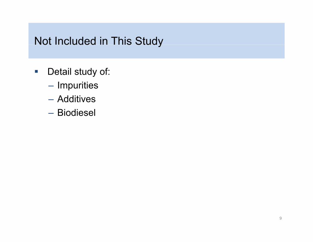
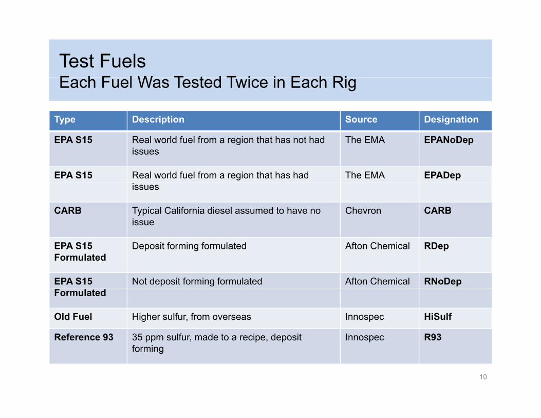
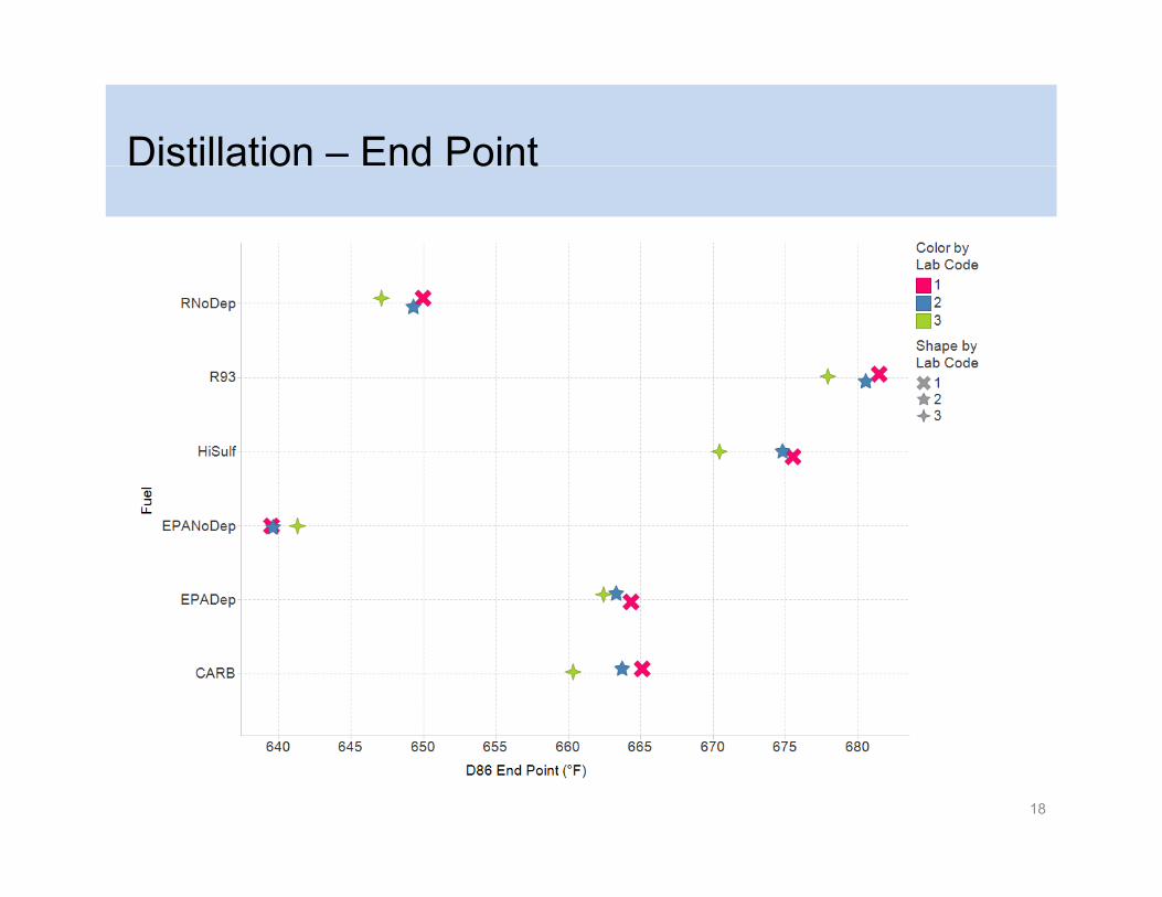

Metal Content by ICPeta Co te t by C
23Metals were by ICP One lab used EN 14538 (IP 547) one lab used D5185 and one lab used proprietary ICP All were below detection limits
Metal Content by ICPeta Co te t by C
Metals were by ICP One lab used EN 14538 (IP 547) one lab used D5185 and one lab used proprietary ICP All were near or below detection limits
24
C t ill RiCaterpillar Rig
Caterpillarrsquos Deposit Bench TestCate p a s epos t e c est
Conceived by Caterpillar Inc circa 2006y pndash Patent pending
Simple and versatile setup that allows controlled t f f l d i t b bi d t l t damounts of fuel and air to be combined at an elevated
temperature and pressure over an experimental substrateIntended to replicate conditions that lead to deposit formation in engines and to form representative deposits in a short period of timedeposits in a short period of timeUsed to test both fuels and oilsConsidered a research toolConsidered a research tool
26
Use of the Deposit Bench Test at CaterpillarTest condition can be varied See ldquoTest Procedurerdquo
Example 1 Confirmed impact of fuel system cleaner ndash simulated field observations
Fuel Fuel + Deposit Forming Additive
Fuel + Deposit Forming
Fuel + Deposit Forming Additive
Fuel + Deposit Forming g g
Additive + Low Dose Cleaner
g Then High Dose
Cleaner
gAdditive Then
Low Dose Cleaner
27
Use of the Deposit Bench Test at CaterpillarUse o t e epos t e c est at Cate p a
Example 2 Studied impact of fuel additives on fuel deposit propensityndash Open Forum SAE Congress Detroit MI April 15 2010
28
Test Procedureest ocedu e
Typical operating conditions of the deposit bench testndash Pressure 1000 psigndash Temperature180 ndash 250degCndash Airfuel ratio 5 ndash 10 by volumendash Test fuel required 300 mL
Test duration 5 hrs
Deposits collected on the substrate (springs and rod) are considered representative of ldquostickyrdquo internal injector deposits or those that form on a metal surface in an enginendash Test duration 5 hrs
Parameters measuredndash Mass of deposit collected on test substrate
M f d it ll t d 40 d 7 filtndash Mass of deposit collected on 40 microm and 7 microm filtersbull Deposits dried in vacuum oven at ~125degC for 16 hrs before weighing
ndash In some cases analytical analysis of deposits filters and tested fuels was conductedbull FTIR TPO SEM EDS etc Filter deposits are considered representative of
test fluid oxidationCleaning between tests
ndash The setup is rinsed by circulating solventsbull Presently pentane then acetonebull Historically heptane
test fluid oxidation
ndash If necessary the entire system can be dismantled and cleaned with a brush and acetonebull All Swagelok fittings and tubing can be replaced at low cost
29
Deposit Bench Apparatusepos t e c ppa atus
40 microm 7 microm
30
Fuel FuelAir MixtureAir Location of Substrate (see inset) Inside Reactor
Test Procedureest ocedu e
A 300 mL test fuel sump can be heated and stirred as necessaryFuel (pink) passes through a 10 microm suction filter and is pumped and metered to 1000 psig at 5 mLminThe fuel is then heated to 180degC as it travels to the reactorPressurized air at 1000 psig (blue) at 180degC and 25 mLmin joins the fuel line tube-in-tube before entering the reactor Inside the reactor the deposit substrate (yellow) consists of two steel springs supported on a steel rod This substrate is weighedsteel springs supported on a steel rod This substrate is weighed before and after testing to measure deposit accumulation (Heat tape and insulation have been removed from the reactor for clarity)The oxidized airfuel mixture (orange) passes out of the reactorThe oxidized airfuel mixture (orange) passes out of the reactor through 40 microm and 7microm filters and finally through the back-pressure regulator Fuel returns to the sump at atmospheric pressure and is recirculated
31
CRC Test PlanC C est a
Test FuelsOld Fuel (HS) EPA S15
(Deposit Forming)
EPA S15 (Not Deposit Forming)
EPA S15 (Real World No Issues)
EPA S15 (Real World With Issues)
CARB Reference 93 (35 ppm S Deposit Forming)
P1102-2413-A R11001612 with NaOH
R11001595 Detroit John Deere D8233 P1011-7749-A
F els ere tested in three stages
with NaOH
P1102-2413-B R11001612 without NaOH
R11001595-B Detroit2 D8236 P1011-7749-B
Fuels were tested in three stagesndash Each stage of testing conducted by a different teamndash May be variation in test operation
bull Cleaning and setup proceduresg p pbull Air flow rates
It was observed that a fuel could ldquoflashrdquo during testing If this occurred large amounts of deposits resulted
ndash This may have happened without notice by the operator during early testing
32
C t ill RiCaterpillar Rig
Data Presentation and CommentsNote Due to timing and internal organization fuels were tested in three stages each by a different team
Deposit Results ndash Substrate Depositsepos t esu ts Subst ate epos ts
Many but not all of the results were repeatable
025
03Team 1 - Substrate Deposits
0 1
015
02
epos
it M
ass
(g)
0
005
01De
34
Deposit Results ndash Substrate Depositsepos t esu ts Subst ate epos ts
Adding NaOH did not cause deposits in all fuels
0025
003Team 2 amp 3 - Substrate Deposits
001
0015
002
epos
it M
ass
(g)
0
0005
001
De
N tNotes The John Deere fuel test was shut down prior to completion due to excessive deposits clogging the system
The Cat Reference-3 test occurred after known system contamination The difference between this measurement and the other Cat Reference measurements is likely due to insufficient system decontamination
35
Deposit Results ndash Filter Depositsepos t esu ts te epos ts
Obvious differences from the substrate deposits
0 14
016
018
02Team 1 - Filter Deposits
008
01
012
014
epos
it M
ass
(g)
0
002
004
006De
36
Deposit Results ndash Filter Depositsepos t esu ts te epos ts
0025
003
)
Teams 2 amp 3 - Filter Deposits
001
0015
002
epos
it M
ass
(g)
0
0005
0 0
D
NotesNotes The John Deere fuel test was shut down prior to completion due to excessive deposits clogging the system
The Cat Reference-3 test occurred after known system contamination The difference between this measurement and the other Cat Reference measurements is likely due to insufficient system decontamination
37
Caterpillar Observations and ConclusionsCate p a Obse at o s a d Co c us o s
Substrate deposit mass and filter deposit mass are the primary metrics of fuel deposit propensitydeposit propensityThe system is sensitive to changes in the operation details
ndash Demonstrated difficulty in data repeatabilitybull Some data was repeatable but not all
The system history can impact datandash Tests run after known system contamination seemed to have unusually high amounts of
deposits
In many cases the amount of deposits generated was small enough toIn many cases the amount of deposits generated was small enough to challenge the detection limit of the balance used
ndash Test conditions should be optimized to produce more measurable results and more differentiation
The test rig may better represent some types of deposits than othersThe test rig may better represent some types of deposits than othersndash Oxidation-driven deposits are the prime target of the rig
5-hour test time may not be optimum for all fuelsndash Different fuels may experience a different amount of degradation in 5 hours
38
CAT CATERPILLAR their respective logos ldquoCaterpillar Yellowrdquo the ldquoPower Edgerdquo trade dress as well as corporate and productidentity used herein are trademarks of Caterpillar and may not be used without permission
copy2012 Caterpillar All Rights Reserved
C t ill RiCaterpillar Rig
More Formal Data AnalysisNote Due to timing and internal organization fuels were tested in three stages each by a different team
All Data ndash Trellised by Teamata e sed by ea
T i d d i d iTest terminated due to excessive deposits
40
Teams 2 and 3 ndash Trellised by Teamea s a d 3 e sed by ea
Test terminated due to excessive deposits
41
All Data ndash Trellised by Teamata e sed by ea
Test terminated due to excessive deposits
42
Teams 2 and 3 ndash Trellised by Teamea s a d 3 e sed by ea
Test terminated due to excessive deposits
43
I RiInnospec Rig
Methodologyet odo ogy
Injector rig conditions used for the program
Variable Setting
Injectors 4 new Bosch CRIN1 injectors per runper run
Filters 2 new Fleetguard FF167 filters per run
Pre-rig clean Repeat rinses with MeOH MEPP (Methoxy Propoxy Propanol) and test diesel
Run time 100 hours
Cycle Standard rig test cycle
Injector tip temperature 180ordmC
Fuel tank temperature 35ordmC
Fuel volume 32 litres
RPM flywheel 1200
45
Analysisa ys s
The following tests were carried out to measure deposition rates
Component Test Measurement Testing Details
Filter Insoluble Carbon Total carbon from both filters by TPO (microgcm-2)
Performed in triplicate on both filters from runy ( g )
See next page for definition of TPO
Injector Back Leakage Change in performance from new injector
Performed in duplicate on each injector
Injector Pressure Drop Change in performance from new injector
5 tests on each injector
I j t I j t Ti D it N li d bl k t d T t f d ll 4Injector Injector Tip Deposit Normalized blank corrected carbon deposit level by TPO
Test performed on all 4 injectors from run
Injector Injector Needle Deposit
Injector Injector Push Rod Deposit
46
Temperature Programmed Oxidation (TPO)e pe atu e og a ed O dat o ( O)
Sample is placed in a quartz sample boat and inserted into a temperature-controlled furnace where it is heated in a calibrated oxygen atmosphere Oxygen feed rate = 0 75 liters perOxygen feed rate 075 liters per minuteStarting temperature = 270degC For testing the temperature was increased to 700degC at a rate of 100degC per minute The CO2 resulting from the oxidation of the carbon is detected by calibrated IR detectorsdetectors Total carbon result calculated from amount of CO2 ndash can either be expressed per unit area (if known) or e p essed pe u t a ea ( o ) onormalized to a surface area = 1
47
I RiInnospec Rig
Data Presentation and Comments
Analysis ndash Insoluble Filter Depositsa ys s so ub e te epos ts
Both fuel tank filters removed and dismantled5 x 1 cm vertical sections removed for analysis from each filterEach section placed in 60 mLEach section placed in 60 mL tri-solvent (602020 toluene acetonemethanol) and placed in an ultrasonic bath for 30 minutesSolvent then filtered through 07-micron GF filter paperFilter paper rinsed with 2 x 25 mL washes of isooctane and dried atwashes of isooctane and dried at 100degC for 2 hoursTest performed in triplicate on both filters
49
CRC Testing ndash Filter DepositsC C est g te epos ts
Each GF filter paper run on RC612 TPO analyzer
Run Fuel Average Total Carbon Deposit (microgcm2)analyzer
Sample was run under ramp method from 270degC to 700degCTotal carbon calculated per unit area of original fuel tank filter paper (10 cm2)
Deposit (microgcm )
1 RNoDep 10837
2 RDep 8837
3 EPANoDep 16650original fuel tank filter paper (10 cm )Results quoted as average total carbon for both filters
p
4 EPADep 10360
5 R93 8013
6 HiSulf 6650
ObservationsHi Sulf R93 and CARB gave lowest resultsIncreased filter deposits observed in Runs 3 and 14 following NaOH-treated runs
f 2 d 13 ti l i
7 CARB 7343
8 CARB 7380
9 HiSulf 8127
of 2 and 13 ndash suggesting cleaning process not removing all NaOH as second run with same fuel gave appreciably different resultsVery good repeatability achieved with the exception of runs that followed NaOH
10 R93 6550
11 EPADep 8350
12 EPANoDep 9323
13 RDep 67 53exception of runs that followed NaOH addition (3 and 14)
13 RDep 6753
14 RNoDep 7377
50
Injector Testingjecto est g
Each injector removed from rig and mounted in DIT31 Injector TesterEach injector measured pre- and post-test for
Back leakagendash Back leakagendash Pressure drop
Result quoted is differencebetween pre- and post-testbetween pre and post test
51
CRC Testing ndash Back LeakageC C est g ac ea age
Test performed in duplicate on each of all 4 injectors Run Fuel Average Change
(Pre- to Post-Test)Secondsall 4 injectorsResults quoted are the average change for all injectors from each runInjector is pressurised to 1100 barAir supply is switched off and the pressure
(Pre- to Post-Test)Seconds
1 RNoDep -563
2 RDep -508
3 EPANoDep 185allowed to return to ambientBack leakage is quoted as the time taken to fall from 600 to 200 barThe faster the time the greater the likelihood of injector seal failure
p
4 EPADep -250
5 R93 401
6 HiSulf -318likelihood of injector seal failure The higher the negative value the greater the loss of performance
Observations
7 CARB -659
8 CARB -099
9 HiSulf -408
High degree of variability between batches of same fuelDifficult to quantify significant changes in performanceNot recommended as a performance
10 R93 -323
11 EPADep -154
12 EPANoDep -248
13 RDep -4 55Not recommended as a performance measurement
13 RDep -455
14 RNoDep -098
52
CRC Testing ndash Pressure DropC C est g essu e op
Test performed 5 times on each of all 4 injectors Run Fuel Average Change
(Pre- to Post-Test)BarinjectorsResults quoted are the average change for all injectors from each runInjector is pressurised to 1100 barAir supply is switched off and the pressure
(Pre- to Post-Test)Bar
1 RNoDep 015
2 RDep 280
3 EPANoDep 455pp y pallowed to return to ambientAt 750 bar the injector is fired for 8 msThe pressure drop during firing is measured in barA i ifi t f ll i d f t t t
p
4 EPADep 245
5 R93 400
6 HiSulf 470A significant fall in pressure drop from start to finish is indicative of deposit buildupAn significant increase in pressure drop could be indicative of injectorlsquostickingrsquo
C l i (t d t )
7 CARB 145
8 CARB -213
9 HiSulf 387
Conclusions (to date)High degree of variability between batches of same fuelDifficult to quantify significant changes in performance
10 R93 1030
11 EPADep -205
12 EPANoDep 245
13 RDep 0 95performanceNot recommended as a performance measurement
13 RDep 095
14 RNoDep 735
53
Injector Dismantlingjecto s a t g
All 4 injectors from each run dismantled3 t t i d f l i3 parts retained for analysis
ndash Tipndash Needlendash Pushrod
Parts rinsed in toluene then acetone then dried in oven for 2 hoursTPO analysis performed on all 4 injectors from each run ndashfinal result is average of 4 testsFi l d it l l l l t d b i b l lFinal deposit level calculated by measuring carbon levels and subtracting blank injector resultTip and needle analysis too variable ndash did not differentiate between fuels
54
CRC Testing ndash Injector TipC C est g jecto p
Run Fuel Average Total Carbon Deposit (microgcm2)
Each tip sectioned using diamond saw to allow testing of tip section exposed in rig Deposit (microgcm2)
1 RNoDep -598
2 RDep 467
3 EPANoDep -533
allow testing of tip section exposed in rigSample run on RC612 TPO analyzer from 270degC to 700degCEach test was baseline corrected against a new pushrod p
4 EPADep -698
5 R93 15785
6 HiSulf 333
new pushrodResults are based on a fixed surface area of 1 cm2
Conclusions (to date)7 CARB 1763
8 CARB -073
9 HiSulf -367
Conclusions (to date)Excess variability in results ndash most likely to be due to washing effect in post-injector drain (C of V typically gt100)Difficult to draw any conclusions ndash analysis
10 R93 6068
11 EPADep 3973
12 EPANoDep -280
13 RDep 30 10
y ynot satisfactory in current form Variation in test resulted in some totals being less than blank needleNot recommended as a performance
d i d b 13 RDep 3010
14 RNoDep 3045
55
measurement ndash drain needs to be redesigned
CRC Testing ndash Injector NeedleC C est g jecto eed e
Each needle sectioned using diamond saw to allow testing of needle section with no Run Fuel Average Total Carbon
Deposit (microgcm2)to allow testing of needle section with no DLC coatingSample run on RC612 TPO analyser from 270degC to 700degCEach test was baseline corrected against a
Deposit (microgcm2)
1 RNoDep -010
2 RDep 163
3 EPANoDep 283Each test was baseline corrected against a new pushrodResults are based on a fixed surface area of 1 cm2
p
4 EPADep 030
5 R93 133
6 HiSulf -143
Conclusions (to date)Excess variability in results ndash most likely to be due to minute levels of deposit on section (C of V typically gt100)
7 CARB 885
8 CARB 367
9 HiSulf 510
Difficult to draw any conclusions ndash analysis not satisfactory in current form Variation in test resulted in some totals being less than blank needleNot recommended as performance
10 R93 1453
11 EPADep 1333
12 EPANoDep 133
13 RDep 13 15Not recommended as performance measurement
13 RDep 1315
14 RNoDep 1478
56
CRC Testing ndash Injector Push RodC C est g jecto us od
Each pushrod run on RC612 TPO analyzer from 270degC to 700degC Run Fuel Average Total Carbon
Deposit (microgcm2)from 270 C to 700 CEach test was baseline corrected against a new pushrodResults are based on a fixed surface area of 1 cm2
Deposit (microgcm2)
1 RNoDep 1620
2 RDep 1538
3 EPANoDep 1735p
4 EPADep 1103
5 R93 1187
6 HiSulf 900
ConclusionsAll fuels created deposits on the pushrodVery good repeatability achieved with the
7 CARB 1863
8 CARB 1590
9 HiSulf 1098Very good repeatability achieved with the exception of Runs 3 and 14 that followed NaOH addition Runs 2 and 13EPADep and HiSulf gave lowest resultsRNoDep gave highest results but this may be skewed by previous run
10 R93 1493
11 EPADep 1215
12 EPANoDep 1220
13 RDep 14 10be skewed by previous runTest appears to differentiate between fuels
13 RDep 1410
14 RNoDep 3548
57
Innospec Rig Summary ndash Prorsquosospec g Su a y o s
Two tests identified as showing differentiation between fuels with good repeatability
ndash Total insoluble carbon from post-tank filtersndash Carbon deposit level on injector pushrod
Rig config ration no reliable no breakdo ns d ring testingRig configuration now reliable ndash no breakdowns during testingRig uses real engine parts filters common rail pump and injectorsRig set up as close as possible to engine test without combustionRi h th t ti l t t f di l i j t ld h t bRig has the potential to use any type of diesel injector ndash would have to be discussed with manufacturer
58
Innospec Rig Summary ndash Conrsquosospec g Su a y Co s
Equipment costly to install Initially rig ~$100K TPO analyzer $70KRig adapted in-house since purchase to include injector heaters and extraction cabinetEquipment manufacturer relatively small company ndash limited supportTest is costly ndash $2K for injectors and filters per test 3 man-days (cost = )Test is costly $2K for injectors and filters per test 3 man days (cost ) required per test including analysis (not including periodic monitoring during test) Test takes 100 hours analysis ~8 hoursO i ht i i d t t it d d i i ht iOvernight running required ndash test monitored during night runningCleaning step is potentially hazardous time consuming and unsuitable for a bench rig ndash up to 75 liters of solvent and fuel required (in total for cleaning)g)Running NaOH in rig may have adversely affected subsequent runsRig conditions may not be severe enough to establish clear differences between fuelsFurther work may be required to improve injector drainage systemFurther work may be required to improve injector drainage systemFor true correlation test would have to be run against actual engine data
59
I RiInnospec Rig
More Formal Data Analysis
Filters Average Total Insoluble Carbon Deposit (microgcmsup2)
61
Filters Average Total Insoluble Carbon Deposit (microgcmsup2)
Pairs of fuel with overlapping intervals were not significantly (α=005) different from each other
62
Filters Average Total Insoluble Carbon Deposit (microgcmsup2)
resi
dual
sud
entiz
ed
Stu
63
Injector Pushrod TPO Carbon Deposit (microgcmsup2)
64
IPRAvg = average of four injectors IPROSA = outlier screened average
Injector Pushrod TPO Carbon Deposit (microgcmsup2)
Outlier Screened AverageOutlier Screened Average
Pairs of fuel with overlapping intervals were not significantly (α=005) different from each other
65
Outlier Screened Average
Injector Pushrod TPO Carbon Deposit (microgcmsup2)
Outlier Screened Averagere
sidu
als
uden
tized
S
tu
66
ConclusionsCo c us o s
Results from this scoping study did not confirm that p g yeither one of these rigs in their present state could discriminate among deposit forming and not deposit forming fuelsforming fuelsIf in-house work by either sponsor results in changes to provide differentiation CRC will consider further evaluationA new rig offered by Delphi is being considered
67
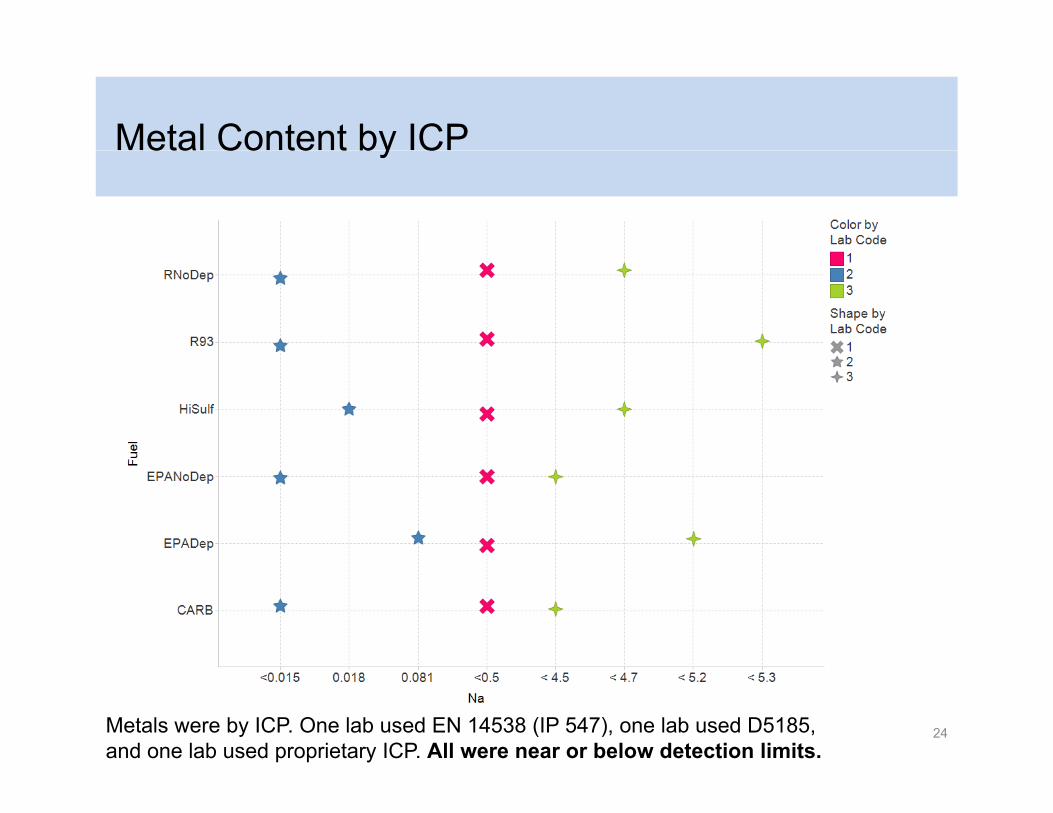
Metal Content by ICPeta Co te t by C
Metals were by ICP One lab used EN 14538 (IP 547) one lab used D5185 and one lab used proprietary ICP All were near or below detection limits
24
C t ill RiCaterpillar Rig
Caterpillarrsquos Deposit Bench TestCate p a s epos t e c est
Conceived by Caterpillar Inc circa 2006y pndash Patent pending
Simple and versatile setup that allows controlled t f f l d i t b bi d t l t damounts of fuel and air to be combined at an elevated
temperature and pressure over an experimental substrateIntended to replicate conditions that lead to deposit formation in engines and to form representative deposits in a short period of timedeposits in a short period of timeUsed to test both fuels and oilsConsidered a research toolConsidered a research tool
26
Use of the Deposit Bench Test at CaterpillarTest condition can be varied See ldquoTest Procedurerdquo
Example 1 Confirmed impact of fuel system cleaner ndash simulated field observations
Fuel Fuel + Deposit Forming Additive
Fuel + Deposit Forming
Fuel + Deposit Forming Additive
Fuel + Deposit Forming g g
Additive + Low Dose Cleaner
g Then High Dose
Cleaner
gAdditive Then
Low Dose Cleaner
27
Use of the Deposit Bench Test at CaterpillarUse o t e epos t e c est at Cate p a
Example 2 Studied impact of fuel additives on fuel deposit propensityndash Open Forum SAE Congress Detroit MI April 15 2010
28
Test Procedureest ocedu e
Typical operating conditions of the deposit bench testndash Pressure 1000 psigndash Temperature180 ndash 250degCndash Airfuel ratio 5 ndash 10 by volumendash Test fuel required 300 mL
Test duration 5 hrs
Deposits collected on the substrate (springs and rod) are considered representative of ldquostickyrdquo internal injector deposits or those that form on a metal surface in an enginendash Test duration 5 hrs
Parameters measuredndash Mass of deposit collected on test substrate
M f d it ll t d 40 d 7 filtndash Mass of deposit collected on 40 microm and 7 microm filtersbull Deposits dried in vacuum oven at ~125degC for 16 hrs before weighing
ndash In some cases analytical analysis of deposits filters and tested fuels was conductedbull FTIR TPO SEM EDS etc Filter deposits are considered representative of
test fluid oxidationCleaning between tests
ndash The setup is rinsed by circulating solventsbull Presently pentane then acetonebull Historically heptane
test fluid oxidation
ndash If necessary the entire system can be dismantled and cleaned with a brush and acetonebull All Swagelok fittings and tubing can be replaced at low cost
29
Deposit Bench Apparatusepos t e c ppa atus
40 microm 7 microm
30
Fuel FuelAir MixtureAir Location of Substrate (see inset) Inside Reactor
Test Procedureest ocedu e
A 300 mL test fuel sump can be heated and stirred as necessaryFuel (pink) passes through a 10 microm suction filter and is pumped and metered to 1000 psig at 5 mLminThe fuel is then heated to 180degC as it travels to the reactorPressurized air at 1000 psig (blue) at 180degC and 25 mLmin joins the fuel line tube-in-tube before entering the reactor Inside the reactor the deposit substrate (yellow) consists of two steel springs supported on a steel rod This substrate is weighedsteel springs supported on a steel rod This substrate is weighed before and after testing to measure deposit accumulation (Heat tape and insulation have been removed from the reactor for clarity)The oxidized airfuel mixture (orange) passes out of the reactorThe oxidized airfuel mixture (orange) passes out of the reactor through 40 microm and 7microm filters and finally through the back-pressure regulator Fuel returns to the sump at atmospheric pressure and is recirculated
31
CRC Test PlanC C est a
Test FuelsOld Fuel (HS) EPA S15
(Deposit Forming)
EPA S15 (Not Deposit Forming)
EPA S15 (Real World No Issues)
EPA S15 (Real World With Issues)
CARB Reference 93 (35 ppm S Deposit Forming)
P1102-2413-A R11001612 with NaOH
R11001595 Detroit John Deere D8233 P1011-7749-A
F els ere tested in three stages
with NaOH
P1102-2413-B R11001612 without NaOH
R11001595-B Detroit2 D8236 P1011-7749-B
Fuels were tested in three stagesndash Each stage of testing conducted by a different teamndash May be variation in test operation
bull Cleaning and setup proceduresg p pbull Air flow rates
It was observed that a fuel could ldquoflashrdquo during testing If this occurred large amounts of deposits resulted
ndash This may have happened without notice by the operator during early testing
32
C t ill RiCaterpillar Rig
Data Presentation and CommentsNote Due to timing and internal organization fuels were tested in three stages each by a different team
Deposit Results ndash Substrate Depositsepos t esu ts Subst ate epos ts
Many but not all of the results were repeatable
025
03Team 1 - Substrate Deposits
0 1
015
02
epos
it M
ass
(g)
0
005
01De
34
Deposit Results ndash Substrate Depositsepos t esu ts Subst ate epos ts
Adding NaOH did not cause deposits in all fuels
0025
003Team 2 amp 3 - Substrate Deposits
001
0015
002
epos
it M
ass
(g)
0
0005
001
De
N tNotes The John Deere fuel test was shut down prior to completion due to excessive deposits clogging the system
The Cat Reference-3 test occurred after known system contamination The difference between this measurement and the other Cat Reference measurements is likely due to insufficient system decontamination
35
Deposit Results ndash Filter Depositsepos t esu ts te epos ts
Obvious differences from the substrate deposits
0 14
016
018
02Team 1 - Filter Deposits
008
01
012
014
epos
it M
ass
(g)
0
002
004
006De
36
Deposit Results ndash Filter Depositsepos t esu ts te epos ts
0025
003
)
Teams 2 amp 3 - Filter Deposits
001
0015
002
epos
it M
ass
(g)
0
0005
0 0
D
NotesNotes The John Deere fuel test was shut down prior to completion due to excessive deposits clogging the system
The Cat Reference-3 test occurred after known system contamination The difference between this measurement and the other Cat Reference measurements is likely due to insufficient system decontamination
37
Caterpillar Observations and ConclusionsCate p a Obse at o s a d Co c us o s
Substrate deposit mass and filter deposit mass are the primary metrics of fuel deposit propensitydeposit propensityThe system is sensitive to changes in the operation details
ndash Demonstrated difficulty in data repeatabilitybull Some data was repeatable but not all
The system history can impact datandash Tests run after known system contamination seemed to have unusually high amounts of
deposits
In many cases the amount of deposits generated was small enough toIn many cases the amount of deposits generated was small enough to challenge the detection limit of the balance used
ndash Test conditions should be optimized to produce more measurable results and more differentiation
The test rig may better represent some types of deposits than othersThe test rig may better represent some types of deposits than othersndash Oxidation-driven deposits are the prime target of the rig
5-hour test time may not be optimum for all fuelsndash Different fuels may experience a different amount of degradation in 5 hours
38
CAT CATERPILLAR their respective logos ldquoCaterpillar Yellowrdquo the ldquoPower Edgerdquo trade dress as well as corporate and productidentity used herein are trademarks of Caterpillar and may not be used without permission
copy2012 Caterpillar All Rights Reserved
C t ill RiCaterpillar Rig
More Formal Data AnalysisNote Due to timing and internal organization fuels were tested in three stages each by a different team
All Data ndash Trellised by Teamata e sed by ea
T i d d i d iTest terminated due to excessive deposits
40
Teams 2 and 3 ndash Trellised by Teamea s a d 3 e sed by ea
Test terminated due to excessive deposits
41
All Data ndash Trellised by Teamata e sed by ea
Test terminated due to excessive deposits
42
Teams 2 and 3 ndash Trellised by Teamea s a d 3 e sed by ea
Test terminated due to excessive deposits
43
I RiInnospec Rig
Methodologyet odo ogy
Injector rig conditions used for the program
Variable Setting
Injectors 4 new Bosch CRIN1 injectors per runper run
Filters 2 new Fleetguard FF167 filters per run
Pre-rig clean Repeat rinses with MeOH MEPP (Methoxy Propoxy Propanol) and test diesel
Run time 100 hours
Cycle Standard rig test cycle
Injector tip temperature 180ordmC
Fuel tank temperature 35ordmC
Fuel volume 32 litres
RPM flywheel 1200
45
Analysisa ys s
The following tests were carried out to measure deposition rates
Component Test Measurement Testing Details
Filter Insoluble Carbon Total carbon from both filters by TPO (microgcm-2)
Performed in triplicate on both filters from runy ( g )
See next page for definition of TPO
Injector Back Leakage Change in performance from new injector
Performed in duplicate on each injector
Injector Pressure Drop Change in performance from new injector
5 tests on each injector
I j t I j t Ti D it N li d bl k t d T t f d ll 4Injector Injector Tip Deposit Normalized blank corrected carbon deposit level by TPO
Test performed on all 4 injectors from run
Injector Injector Needle Deposit
Injector Injector Push Rod Deposit
46
Temperature Programmed Oxidation (TPO)e pe atu e og a ed O dat o ( O)
Sample is placed in a quartz sample boat and inserted into a temperature-controlled furnace where it is heated in a calibrated oxygen atmosphere Oxygen feed rate = 0 75 liters perOxygen feed rate 075 liters per minuteStarting temperature = 270degC For testing the temperature was increased to 700degC at a rate of 100degC per minute The CO2 resulting from the oxidation of the carbon is detected by calibrated IR detectorsdetectors Total carbon result calculated from amount of CO2 ndash can either be expressed per unit area (if known) or e p essed pe u t a ea ( o ) onormalized to a surface area = 1
47
I RiInnospec Rig
Data Presentation and Comments
Analysis ndash Insoluble Filter Depositsa ys s so ub e te epos ts
Both fuel tank filters removed and dismantled5 x 1 cm vertical sections removed for analysis from each filterEach section placed in 60 mLEach section placed in 60 mL tri-solvent (602020 toluene acetonemethanol) and placed in an ultrasonic bath for 30 minutesSolvent then filtered through 07-micron GF filter paperFilter paper rinsed with 2 x 25 mL washes of isooctane and dried atwashes of isooctane and dried at 100degC for 2 hoursTest performed in triplicate on both filters
49
CRC Testing ndash Filter DepositsC C est g te epos ts
Each GF filter paper run on RC612 TPO analyzer
Run Fuel Average Total Carbon Deposit (microgcm2)analyzer
Sample was run under ramp method from 270degC to 700degCTotal carbon calculated per unit area of original fuel tank filter paper (10 cm2)
Deposit (microgcm )
1 RNoDep 10837
2 RDep 8837
3 EPANoDep 16650original fuel tank filter paper (10 cm )Results quoted as average total carbon for both filters
p
4 EPADep 10360
5 R93 8013
6 HiSulf 6650
ObservationsHi Sulf R93 and CARB gave lowest resultsIncreased filter deposits observed in Runs 3 and 14 following NaOH-treated runs
f 2 d 13 ti l i
7 CARB 7343
8 CARB 7380
9 HiSulf 8127
of 2 and 13 ndash suggesting cleaning process not removing all NaOH as second run with same fuel gave appreciably different resultsVery good repeatability achieved with the exception of runs that followed NaOH
10 R93 6550
11 EPADep 8350
12 EPANoDep 9323
13 RDep 67 53exception of runs that followed NaOH addition (3 and 14)
13 RDep 6753
14 RNoDep 7377
50
Injector Testingjecto est g
Each injector removed from rig and mounted in DIT31 Injector TesterEach injector measured pre- and post-test for
Back leakagendash Back leakagendash Pressure drop
Result quoted is differencebetween pre- and post-testbetween pre and post test
51
CRC Testing ndash Back LeakageC C est g ac ea age
Test performed in duplicate on each of all 4 injectors Run Fuel Average Change
(Pre- to Post-Test)Secondsall 4 injectorsResults quoted are the average change for all injectors from each runInjector is pressurised to 1100 barAir supply is switched off and the pressure
(Pre- to Post-Test)Seconds
1 RNoDep -563
2 RDep -508
3 EPANoDep 185allowed to return to ambientBack leakage is quoted as the time taken to fall from 600 to 200 barThe faster the time the greater the likelihood of injector seal failure
p
4 EPADep -250
5 R93 401
6 HiSulf -318likelihood of injector seal failure The higher the negative value the greater the loss of performance
Observations
7 CARB -659
8 CARB -099
9 HiSulf -408
High degree of variability between batches of same fuelDifficult to quantify significant changes in performanceNot recommended as a performance
10 R93 -323
11 EPADep -154
12 EPANoDep -248
13 RDep -4 55Not recommended as a performance measurement
13 RDep -455
14 RNoDep -098
52
CRC Testing ndash Pressure DropC C est g essu e op
Test performed 5 times on each of all 4 injectors Run Fuel Average Change
(Pre- to Post-Test)BarinjectorsResults quoted are the average change for all injectors from each runInjector is pressurised to 1100 barAir supply is switched off and the pressure
(Pre- to Post-Test)Bar
1 RNoDep 015
2 RDep 280
3 EPANoDep 455pp y pallowed to return to ambientAt 750 bar the injector is fired for 8 msThe pressure drop during firing is measured in barA i ifi t f ll i d f t t t
p
4 EPADep 245
5 R93 400
6 HiSulf 470A significant fall in pressure drop from start to finish is indicative of deposit buildupAn significant increase in pressure drop could be indicative of injectorlsquostickingrsquo
C l i (t d t )
7 CARB 145
8 CARB -213
9 HiSulf 387
Conclusions (to date)High degree of variability between batches of same fuelDifficult to quantify significant changes in performance
10 R93 1030
11 EPADep -205
12 EPANoDep 245
13 RDep 0 95performanceNot recommended as a performance measurement
13 RDep 095
14 RNoDep 735
53
Injector Dismantlingjecto s a t g
All 4 injectors from each run dismantled3 t t i d f l i3 parts retained for analysis
ndash Tipndash Needlendash Pushrod
Parts rinsed in toluene then acetone then dried in oven for 2 hoursTPO analysis performed on all 4 injectors from each run ndashfinal result is average of 4 testsFi l d it l l l l t d b i b l lFinal deposit level calculated by measuring carbon levels and subtracting blank injector resultTip and needle analysis too variable ndash did not differentiate between fuels
54
CRC Testing ndash Injector TipC C est g jecto p
Run Fuel Average Total Carbon Deposit (microgcm2)
Each tip sectioned using diamond saw to allow testing of tip section exposed in rig Deposit (microgcm2)
1 RNoDep -598
2 RDep 467
3 EPANoDep -533
allow testing of tip section exposed in rigSample run on RC612 TPO analyzer from 270degC to 700degCEach test was baseline corrected against a new pushrod p
4 EPADep -698
5 R93 15785
6 HiSulf 333
new pushrodResults are based on a fixed surface area of 1 cm2
Conclusions (to date)7 CARB 1763
8 CARB -073
9 HiSulf -367
Conclusions (to date)Excess variability in results ndash most likely to be due to washing effect in post-injector drain (C of V typically gt100)Difficult to draw any conclusions ndash analysis
10 R93 6068
11 EPADep 3973
12 EPANoDep -280
13 RDep 30 10
y ynot satisfactory in current form Variation in test resulted in some totals being less than blank needleNot recommended as a performance
d i d b 13 RDep 3010
14 RNoDep 3045
55
measurement ndash drain needs to be redesigned
CRC Testing ndash Injector NeedleC C est g jecto eed e
Each needle sectioned using diamond saw to allow testing of needle section with no Run Fuel Average Total Carbon
Deposit (microgcm2)to allow testing of needle section with no DLC coatingSample run on RC612 TPO analyser from 270degC to 700degCEach test was baseline corrected against a
Deposit (microgcm2)
1 RNoDep -010
2 RDep 163
3 EPANoDep 283Each test was baseline corrected against a new pushrodResults are based on a fixed surface area of 1 cm2
p
4 EPADep 030
5 R93 133
6 HiSulf -143
Conclusions (to date)Excess variability in results ndash most likely to be due to minute levels of deposit on section (C of V typically gt100)
7 CARB 885
8 CARB 367
9 HiSulf 510
Difficult to draw any conclusions ndash analysis not satisfactory in current form Variation in test resulted in some totals being less than blank needleNot recommended as performance
10 R93 1453
11 EPADep 1333
12 EPANoDep 133
13 RDep 13 15Not recommended as performance measurement
13 RDep 1315
14 RNoDep 1478
56
CRC Testing ndash Injector Push RodC C est g jecto us od
Each pushrod run on RC612 TPO analyzer from 270degC to 700degC Run Fuel Average Total Carbon
Deposit (microgcm2)from 270 C to 700 CEach test was baseline corrected against a new pushrodResults are based on a fixed surface area of 1 cm2
Deposit (microgcm2)
1 RNoDep 1620
2 RDep 1538
3 EPANoDep 1735p
4 EPADep 1103
5 R93 1187
6 HiSulf 900
ConclusionsAll fuels created deposits on the pushrodVery good repeatability achieved with the
7 CARB 1863
8 CARB 1590
9 HiSulf 1098Very good repeatability achieved with the exception of Runs 3 and 14 that followed NaOH addition Runs 2 and 13EPADep and HiSulf gave lowest resultsRNoDep gave highest results but this may be skewed by previous run
10 R93 1493
11 EPADep 1215
12 EPANoDep 1220
13 RDep 14 10be skewed by previous runTest appears to differentiate between fuels
13 RDep 1410
14 RNoDep 3548
57
Innospec Rig Summary ndash Prorsquosospec g Su a y o s
Two tests identified as showing differentiation between fuels with good repeatability
ndash Total insoluble carbon from post-tank filtersndash Carbon deposit level on injector pushrod
Rig config ration no reliable no breakdo ns d ring testingRig configuration now reliable ndash no breakdowns during testingRig uses real engine parts filters common rail pump and injectorsRig set up as close as possible to engine test without combustionRi h th t ti l t t f di l i j t ld h t bRig has the potential to use any type of diesel injector ndash would have to be discussed with manufacturer
58
Innospec Rig Summary ndash Conrsquosospec g Su a y Co s
Equipment costly to install Initially rig ~$100K TPO analyzer $70KRig adapted in-house since purchase to include injector heaters and extraction cabinetEquipment manufacturer relatively small company ndash limited supportTest is costly ndash $2K for injectors and filters per test 3 man-days (cost = )Test is costly $2K for injectors and filters per test 3 man days (cost ) required per test including analysis (not including periodic monitoring during test) Test takes 100 hours analysis ~8 hoursO i ht i i d t t it d d i i ht iOvernight running required ndash test monitored during night runningCleaning step is potentially hazardous time consuming and unsuitable for a bench rig ndash up to 75 liters of solvent and fuel required (in total for cleaning)g)Running NaOH in rig may have adversely affected subsequent runsRig conditions may not be severe enough to establish clear differences between fuelsFurther work may be required to improve injector drainage systemFurther work may be required to improve injector drainage systemFor true correlation test would have to be run against actual engine data
59
I RiInnospec Rig
More Formal Data Analysis
Filters Average Total Insoluble Carbon Deposit (microgcmsup2)
61
Filters Average Total Insoluble Carbon Deposit (microgcmsup2)
Pairs of fuel with overlapping intervals were not significantly (α=005) different from each other
62
Filters Average Total Insoluble Carbon Deposit (microgcmsup2)
resi
dual
sud
entiz
ed
Stu
63
Injector Pushrod TPO Carbon Deposit (microgcmsup2)
64
IPRAvg = average of four injectors IPROSA = outlier screened average
Injector Pushrod TPO Carbon Deposit (microgcmsup2)
Outlier Screened AverageOutlier Screened Average
Pairs of fuel with overlapping intervals were not significantly (α=005) different from each other
65
Outlier Screened Average
Injector Pushrod TPO Carbon Deposit (microgcmsup2)
Outlier Screened Averagere
sidu
als
uden
tized
S
tu
66
ConclusionsCo c us o s
Results from this scoping study did not confirm that p g yeither one of these rigs in their present state could discriminate among deposit forming and not deposit forming fuelsforming fuelsIf in-house work by either sponsor results in changes to provide differentiation CRC will consider further evaluationA new rig offered by Delphi is being considered
67
C t ill RiCaterpillar Rig
Caterpillarrsquos Deposit Bench TestCate p a s epos t e c est
Conceived by Caterpillar Inc circa 2006y pndash Patent pending
Simple and versatile setup that allows controlled t f f l d i t b bi d t l t damounts of fuel and air to be combined at an elevated
temperature and pressure over an experimental substrateIntended to replicate conditions that lead to deposit formation in engines and to form representative deposits in a short period of timedeposits in a short period of timeUsed to test both fuels and oilsConsidered a research toolConsidered a research tool
26
Use of the Deposit Bench Test at CaterpillarTest condition can be varied See ldquoTest Procedurerdquo
Example 1 Confirmed impact of fuel system cleaner ndash simulated field observations
Fuel Fuel + Deposit Forming Additive
Fuel + Deposit Forming
Fuel + Deposit Forming Additive
Fuel + Deposit Forming g g
Additive + Low Dose Cleaner
g Then High Dose
Cleaner
gAdditive Then
Low Dose Cleaner
27
Use of the Deposit Bench Test at CaterpillarUse o t e epos t e c est at Cate p a
Example 2 Studied impact of fuel additives on fuel deposit propensityndash Open Forum SAE Congress Detroit MI April 15 2010
28
Test Procedureest ocedu e
Typical operating conditions of the deposit bench testndash Pressure 1000 psigndash Temperature180 ndash 250degCndash Airfuel ratio 5 ndash 10 by volumendash Test fuel required 300 mL
Test duration 5 hrs
Deposits collected on the substrate (springs and rod) are considered representative of ldquostickyrdquo internal injector deposits or those that form on a metal surface in an enginendash Test duration 5 hrs
Parameters measuredndash Mass of deposit collected on test substrate
M f d it ll t d 40 d 7 filtndash Mass of deposit collected on 40 microm and 7 microm filtersbull Deposits dried in vacuum oven at ~125degC for 16 hrs before weighing
ndash In some cases analytical analysis of deposits filters and tested fuels was conductedbull FTIR TPO SEM EDS etc Filter deposits are considered representative of
test fluid oxidationCleaning between tests
ndash The setup is rinsed by circulating solventsbull Presently pentane then acetonebull Historically heptane
test fluid oxidation
ndash If necessary the entire system can be dismantled and cleaned with a brush and acetonebull All Swagelok fittings and tubing can be replaced at low cost
29
Deposit Bench Apparatusepos t e c ppa atus
40 microm 7 microm
30
Fuel FuelAir MixtureAir Location of Substrate (see inset) Inside Reactor
Test Procedureest ocedu e
A 300 mL test fuel sump can be heated and stirred as necessaryFuel (pink) passes through a 10 microm suction filter and is pumped and metered to 1000 psig at 5 mLminThe fuel is then heated to 180degC as it travels to the reactorPressurized air at 1000 psig (blue) at 180degC and 25 mLmin joins the fuel line tube-in-tube before entering the reactor Inside the reactor the deposit substrate (yellow) consists of two steel springs supported on a steel rod This substrate is weighedsteel springs supported on a steel rod This substrate is weighed before and after testing to measure deposit accumulation (Heat tape and insulation have been removed from the reactor for clarity)The oxidized airfuel mixture (orange) passes out of the reactorThe oxidized airfuel mixture (orange) passes out of the reactor through 40 microm and 7microm filters and finally through the back-pressure regulator Fuel returns to the sump at atmospheric pressure and is recirculated
31
CRC Test PlanC C est a
Test FuelsOld Fuel (HS) EPA S15
(Deposit Forming)
EPA S15 (Not Deposit Forming)
EPA S15 (Real World No Issues)
EPA S15 (Real World With Issues)
CARB Reference 93 (35 ppm S Deposit Forming)
P1102-2413-A R11001612 with NaOH
R11001595 Detroit John Deere D8233 P1011-7749-A
F els ere tested in three stages
with NaOH
P1102-2413-B R11001612 without NaOH
R11001595-B Detroit2 D8236 P1011-7749-B
Fuels were tested in three stagesndash Each stage of testing conducted by a different teamndash May be variation in test operation
bull Cleaning and setup proceduresg p pbull Air flow rates
It was observed that a fuel could ldquoflashrdquo during testing If this occurred large amounts of deposits resulted
ndash This may have happened without notice by the operator during early testing
32
C t ill RiCaterpillar Rig
Data Presentation and CommentsNote Due to timing and internal organization fuels were tested in three stages each by a different team
Deposit Results ndash Substrate Depositsepos t esu ts Subst ate epos ts
Many but not all of the results were repeatable
025
03Team 1 - Substrate Deposits
0 1
015
02
epos
it M
ass
(g)
0
005
01De
34
Deposit Results ndash Substrate Depositsepos t esu ts Subst ate epos ts
Adding NaOH did not cause deposits in all fuels
0025
003Team 2 amp 3 - Substrate Deposits
001
0015
002
epos
it M
ass
(g)
0
0005
001
De
N tNotes The John Deere fuel test was shut down prior to completion due to excessive deposits clogging the system
The Cat Reference-3 test occurred after known system contamination The difference between this measurement and the other Cat Reference measurements is likely due to insufficient system decontamination
35
Deposit Results ndash Filter Depositsepos t esu ts te epos ts
Obvious differences from the substrate deposits
0 14
016
018
02Team 1 - Filter Deposits
008
01
012
014
epos
it M
ass
(g)
0
002
004
006De
36
Deposit Results ndash Filter Depositsepos t esu ts te epos ts
0025
003
)
Teams 2 amp 3 - Filter Deposits
001
0015
002
epos
it M
ass
(g)
0
0005
0 0
D
NotesNotes The John Deere fuel test was shut down prior to completion due to excessive deposits clogging the system
The Cat Reference-3 test occurred after known system contamination The difference between this measurement and the other Cat Reference measurements is likely due to insufficient system decontamination
37
Caterpillar Observations and ConclusionsCate p a Obse at o s a d Co c us o s
Substrate deposit mass and filter deposit mass are the primary metrics of fuel deposit propensitydeposit propensityThe system is sensitive to changes in the operation details
ndash Demonstrated difficulty in data repeatabilitybull Some data was repeatable but not all
The system history can impact datandash Tests run after known system contamination seemed to have unusually high amounts of
deposits
In many cases the amount of deposits generated was small enough toIn many cases the amount of deposits generated was small enough to challenge the detection limit of the balance used
ndash Test conditions should be optimized to produce more measurable results and more differentiation
The test rig may better represent some types of deposits than othersThe test rig may better represent some types of deposits than othersndash Oxidation-driven deposits are the prime target of the rig
5-hour test time may not be optimum for all fuelsndash Different fuels may experience a different amount of degradation in 5 hours
38
CAT CATERPILLAR their respective logos ldquoCaterpillar Yellowrdquo the ldquoPower Edgerdquo trade dress as well as corporate and productidentity used herein are trademarks of Caterpillar and may not be used without permission
copy2012 Caterpillar All Rights Reserved
C t ill RiCaterpillar Rig
More Formal Data AnalysisNote Due to timing and internal organization fuels were tested in three stages each by a different team
All Data ndash Trellised by Teamata e sed by ea
T i d d i d iTest terminated due to excessive deposits
40
Teams 2 and 3 ndash Trellised by Teamea s a d 3 e sed by ea
Test terminated due to excessive deposits
41
All Data ndash Trellised by Teamata e sed by ea
Test terminated due to excessive deposits
42
Teams 2 and 3 ndash Trellised by Teamea s a d 3 e sed by ea
Test terminated due to excessive deposits
43
I RiInnospec Rig
Methodologyet odo ogy
Injector rig conditions used for the program
Variable Setting
Injectors 4 new Bosch CRIN1 injectors per runper run
Filters 2 new Fleetguard FF167 filters per run
Pre-rig clean Repeat rinses with MeOH MEPP (Methoxy Propoxy Propanol) and test diesel
Run time 100 hours
Cycle Standard rig test cycle
Injector tip temperature 180ordmC
Fuel tank temperature 35ordmC
Fuel volume 32 litres
RPM flywheel 1200
45
Analysisa ys s
The following tests were carried out to measure deposition rates
Component Test Measurement Testing Details
Filter Insoluble Carbon Total carbon from both filters by TPO (microgcm-2)
Performed in triplicate on both filters from runy ( g )
See next page for definition of TPO
Injector Back Leakage Change in performance from new injector
Performed in duplicate on each injector
Injector Pressure Drop Change in performance from new injector
5 tests on each injector
I j t I j t Ti D it N li d bl k t d T t f d ll 4Injector Injector Tip Deposit Normalized blank corrected carbon deposit level by TPO
Test performed on all 4 injectors from run
Injector Injector Needle Deposit
Injector Injector Push Rod Deposit
46
Temperature Programmed Oxidation (TPO)e pe atu e og a ed O dat o ( O)
Sample is placed in a quartz sample boat and inserted into a temperature-controlled furnace where it is heated in a calibrated oxygen atmosphere Oxygen feed rate = 0 75 liters perOxygen feed rate 075 liters per minuteStarting temperature = 270degC For testing the temperature was increased to 700degC at a rate of 100degC per minute The CO2 resulting from the oxidation of the carbon is detected by calibrated IR detectorsdetectors Total carbon result calculated from amount of CO2 ndash can either be expressed per unit area (if known) or e p essed pe u t a ea ( o ) onormalized to a surface area = 1
47
I RiInnospec Rig
Data Presentation and Comments
Analysis ndash Insoluble Filter Depositsa ys s so ub e te epos ts
Both fuel tank filters removed and dismantled5 x 1 cm vertical sections removed for analysis from each filterEach section placed in 60 mLEach section placed in 60 mL tri-solvent (602020 toluene acetonemethanol) and placed in an ultrasonic bath for 30 minutesSolvent then filtered through 07-micron GF filter paperFilter paper rinsed with 2 x 25 mL washes of isooctane and dried atwashes of isooctane and dried at 100degC for 2 hoursTest performed in triplicate on both filters
49
CRC Testing ndash Filter DepositsC C est g te epos ts
Each GF filter paper run on RC612 TPO analyzer
Run Fuel Average Total Carbon Deposit (microgcm2)analyzer
Sample was run under ramp method from 270degC to 700degCTotal carbon calculated per unit area of original fuel tank filter paper (10 cm2)
Deposit (microgcm )
1 RNoDep 10837
2 RDep 8837
3 EPANoDep 16650original fuel tank filter paper (10 cm )Results quoted as average total carbon for both filters
p
4 EPADep 10360
5 R93 8013
6 HiSulf 6650
ObservationsHi Sulf R93 and CARB gave lowest resultsIncreased filter deposits observed in Runs 3 and 14 following NaOH-treated runs
f 2 d 13 ti l i
7 CARB 7343
8 CARB 7380
9 HiSulf 8127
of 2 and 13 ndash suggesting cleaning process not removing all NaOH as second run with same fuel gave appreciably different resultsVery good repeatability achieved with the exception of runs that followed NaOH
10 R93 6550
11 EPADep 8350
12 EPANoDep 9323
13 RDep 67 53exception of runs that followed NaOH addition (3 and 14)
13 RDep 6753
14 RNoDep 7377
50
Injector Testingjecto est g
Each injector removed from rig and mounted in DIT31 Injector TesterEach injector measured pre- and post-test for
Back leakagendash Back leakagendash Pressure drop
Result quoted is differencebetween pre- and post-testbetween pre and post test
51
CRC Testing ndash Back LeakageC C est g ac ea age
Test performed in duplicate on each of all 4 injectors Run Fuel Average Change
(Pre- to Post-Test)Secondsall 4 injectorsResults quoted are the average change for all injectors from each runInjector is pressurised to 1100 barAir supply is switched off and the pressure
(Pre- to Post-Test)Seconds
1 RNoDep -563
2 RDep -508
3 EPANoDep 185allowed to return to ambientBack leakage is quoted as the time taken to fall from 600 to 200 barThe faster the time the greater the likelihood of injector seal failure
p
4 EPADep -250
5 R93 401
6 HiSulf -318likelihood of injector seal failure The higher the negative value the greater the loss of performance
Observations
7 CARB -659
8 CARB -099
9 HiSulf -408
High degree of variability between batches of same fuelDifficult to quantify significant changes in performanceNot recommended as a performance
10 R93 -323
11 EPADep -154
12 EPANoDep -248
13 RDep -4 55Not recommended as a performance measurement
13 RDep -455
14 RNoDep -098
52
CRC Testing ndash Pressure DropC C est g essu e op
Test performed 5 times on each of all 4 injectors Run Fuel Average Change
(Pre- to Post-Test)BarinjectorsResults quoted are the average change for all injectors from each runInjector is pressurised to 1100 barAir supply is switched off and the pressure
(Pre- to Post-Test)Bar
1 RNoDep 015
2 RDep 280
3 EPANoDep 455pp y pallowed to return to ambientAt 750 bar the injector is fired for 8 msThe pressure drop during firing is measured in barA i ifi t f ll i d f t t t
p
4 EPADep 245
5 R93 400
6 HiSulf 470A significant fall in pressure drop from start to finish is indicative of deposit buildupAn significant increase in pressure drop could be indicative of injectorlsquostickingrsquo
C l i (t d t )
7 CARB 145
8 CARB -213
9 HiSulf 387
Conclusions (to date)High degree of variability between batches of same fuelDifficult to quantify significant changes in performance
10 R93 1030
11 EPADep -205
12 EPANoDep 245
13 RDep 0 95performanceNot recommended as a performance measurement
13 RDep 095
14 RNoDep 735
53
Injector Dismantlingjecto s a t g
All 4 injectors from each run dismantled3 t t i d f l i3 parts retained for analysis
ndash Tipndash Needlendash Pushrod
Parts rinsed in toluene then acetone then dried in oven for 2 hoursTPO analysis performed on all 4 injectors from each run ndashfinal result is average of 4 testsFi l d it l l l l t d b i b l lFinal deposit level calculated by measuring carbon levels and subtracting blank injector resultTip and needle analysis too variable ndash did not differentiate between fuels
54
CRC Testing ndash Injector TipC C est g jecto p
Run Fuel Average Total Carbon Deposit (microgcm2)
Each tip sectioned using diamond saw to allow testing of tip section exposed in rig Deposit (microgcm2)
1 RNoDep -598
2 RDep 467
3 EPANoDep -533
allow testing of tip section exposed in rigSample run on RC612 TPO analyzer from 270degC to 700degCEach test was baseline corrected against a new pushrod p
4 EPADep -698
5 R93 15785
6 HiSulf 333
new pushrodResults are based on a fixed surface area of 1 cm2
Conclusions (to date)7 CARB 1763
8 CARB -073
9 HiSulf -367
Conclusions (to date)Excess variability in results ndash most likely to be due to washing effect in post-injector drain (C of V typically gt100)Difficult to draw any conclusions ndash analysis
10 R93 6068
11 EPADep 3973
12 EPANoDep -280
13 RDep 30 10
y ynot satisfactory in current form Variation in test resulted in some totals being less than blank needleNot recommended as a performance
d i d b 13 RDep 3010
14 RNoDep 3045
55
measurement ndash drain needs to be redesigned
CRC Testing ndash Injector NeedleC C est g jecto eed e
Each needle sectioned using diamond saw to allow testing of needle section with no Run Fuel Average Total Carbon
Deposit (microgcm2)to allow testing of needle section with no DLC coatingSample run on RC612 TPO analyser from 270degC to 700degCEach test was baseline corrected against a
Deposit (microgcm2)
1 RNoDep -010
2 RDep 163
3 EPANoDep 283Each test was baseline corrected against a new pushrodResults are based on a fixed surface area of 1 cm2
p
4 EPADep 030
5 R93 133
6 HiSulf -143
Conclusions (to date)Excess variability in results ndash most likely to be due to minute levels of deposit on section (C of V typically gt100)
7 CARB 885
8 CARB 367
9 HiSulf 510
Difficult to draw any conclusions ndash analysis not satisfactory in current form Variation in test resulted in some totals being less than blank needleNot recommended as performance
10 R93 1453
11 EPADep 1333
12 EPANoDep 133
13 RDep 13 15Not recommended as performance measurement
13 RDep 1315
14 RNoDep 1478
56
CRC Testing ndash Injector Push RodC C est g jecto us od
Each pushrod run on RC612 TPO analyzer from 270degC to 700degC Run Fuel Average Total Carbon
Deposit (microgcm2)from 270 C to 700 CEach test was baseline corrected against a new pushrodResults are based on a fixed surface area of 1 cm2
Deposit (microgcm2)
1 RNoDep 1620
2 RDep 1538
3 EPANoDep 1735p
4 EPADep 1103
5 R93 1187
6 HiSulf 900
ConclusionsAll fuels created deposits on the pushrodVery good repeatability achieved with the
7 CARB 1863
8 CARB 1590
9 HiSulf 1098Very good repeatability achieved with the exception of Runs 3 and 14 that followed NaOH addition Runs 2 and 13EPADep and HiSulf gave lowest resultsRNoDep gave highest results but this may be skewed by previous run
10 R93 1493
11 EPADep 1215
12 EPANoDep 1220
13 RDep 14 10be skewed by previous runTest appears to differentiate between fuels
13 RDep 1410
14 RNoDep 3548
57
Innospec Rig Summary ndash Prorsquosospec g Su a y o s
Two tests identified as showing differentiation between fuels with good repeatability
ndash Total insoluble carbon from post-tank filtersndash Carbon deposit level on injector pushrod
Rig config ration no reliable no breakdo ns d ring testingRig configuration now reliable ndash no breakdowns during testingRig uses real engine parts filters common rail pump and injectorsRig set up as close as possible to engine test without combustionRi h th t ti l t t f di l i j t ld h t bRig has the potential to use any type of diesel injector ndash would have to be discussed with manufacturer
58
Innospec Rig Summary ndash Conrsquosospec g Su a y Co s
Equipment costly to install Initially rig ~$100K TPO analyzer $70KRig adapted in-house since purchase to include injector heaters and extraction cabinetEquipment manufacturer relatively small company ndash limited supportTest is costly ndash $2K for injectors and filters per test 3 man-days (cost = )Test is costly $2K for injectors and filters per test 3 man days (cost ) required per test including analysis (not including periodic monitoring during test) Test takes 100 hours analysis ~8 hoursO i ht i i d t t it d d i i ht iOvernight running required ndash test monitored during night runningCleaning step is potentially hazardous time consuming and unsuitable for a bench rig ndash up to 75 liters of solvent and fuel required (in total for cleaning)g)Running NaOH in rig may have adversely affected subsequent runsRig conditions may not be severe enough to establish clear differences between fuelsFurther work may be required to improve injector drainage systemFurther work may be required to improve injector drainage systemFor true correlation test would have to be run against actual engine data
59
I RiInnospec Rig
More Formal Data Analysis
Filters Average Total Insoluble Carbon Deposit (microgcmsup2)
61
Filters Average Total Insoluble Carbon Deposit (microgcmsup2)
Pairs of fuel with overlapping intervals were not significantly (α=005) different from each other
62
Filters Average Total Insoluble Carbon Deposit (microgcmsup2)
resi
dual
sud
entiz
ed
Stu
63
Injector Pushrod TPO Carbon Deposit (microgcmsup2)
64
IPRAvg = average of four injectors IPROSA = outlier screened average
Injector Pushrod TPO Carbon Deposit (microgcmsup2)
Outlier Screened AverageOutlier Screened Average
Pairs of fuel with overlapping intervals were not significantly (α=005) different from each other
65
Outlier Screened Average
Injector Pushrod TPO Carbon Deposit (microgcmsup2)
Outlier Screened Averagere
sidu
als
uden
tized
S
tu
66
ConclusionsCo c us o s
Results from this scoping study did not confirm that p g yeither one of these rigs in their present state could discriminate among deposit forming and not deposit forming fuelsforming fuelsIf in-house work by either sponsor results in changes to provide differentiation CRC will consider further evaluationA new rig offered by Delphi is being considered
67

Test Procedureest ocedu e
Typical operating conditions of the deposit bench testndash Pressure 1000 psigndash Temperature180 ndash 250degCndash Airfuel ratio 5 ndash 10 by volumendash Test fuel required 300 mL
Test duration 5 hrs
Deposits collected on the substrate (springs and rod) are considered representative of ldquostickyrdquo internal injector deposits or those that form on a metal surface in an enginendash Test duration 5 hrs
Parameters measuredndash Mass of deposit collected on test substrate
M f d it ll t d 40 d 7 filtndash Mass of deposit collected on 40 microm and 7 microm filtersbull Deposits dried in vacuum oven at ~125degC for 16 hrs before weighing
ndash In some cases analytical analysis of deposits filters and tested fuels was conductedbull FTIR TPO SEM EDS etc Filter deposits are considered representative of
test fluid oxidationCleaning between tests
ndash The setup is rinsed by circulating solventsbull Presently pentane then acetonebull Historically heptane
test fluid oxidation
ndash If necessary the entire system can be dismantled and cleaned with a brush and acetonebull All Swagelok fittings and tubing can be replaced at low cost
29
Deposit Bench Apparatusepos t e c ppa atus
40 microm 7 microm
30
Fuel FuelAir MixtureAir Location of Substrate (see inset) Inside Reactor
Test Procedureest ocedu e
A 300 mL test fuel sump can be heated and stirred as necessaryFuel (pink) passes through a 10 microm suction filter and is pumped and metered to 1000 psig at 5 mLminThe fuel is then heated to 180degC as it travels to the reactorPressurized air at 1000 psig (blue) at 180degC and 25 mLmin joins the fuel line tube-in-tube before entering the reactor Inside the reactor the deposit substrate (yellow) consists of two steel springs supported on a steel rod This substrate is weighedsteel springs supported on a steel rod This substrate is weighed before and after testing to measure deposit accumulation (Heat tape and insulation have been removed from the reactor for clarity)The oxidized airfuel mixture (orange) passes out of the reactorThe oxidized airfuel mixture (orange) passes out of the reactor through 40 microm and 7microm filters and finally through the back-pressure regulator Fuel returns to the sump at atmospheric pressure and is recirculated
31
CRC Test PlanC C est a
Test FuelsOld Fuel (HS) EPA S15
(Deposit Forming)
EPA S15 (Not Deposit Forming)
EPA S15 (Real World No Issues)
EPA S15 (Real World With Issues)
CARB Reference 93 (35 ppm S Deposit Forming)
P1102-2413-A R11001612 with NaOH
R11001595 Detroit John Deere D8233 P1011-7749-A
F els ere tested in three stages
with NaOH
P1102-2413-B R11001612 without NaOH
R11001595-B Detroit2 D8236 P1011-7749-B
Fuels were tested in three stagesndash Each stage of testing conducted by a different teamndash May be variation in test operation
bull Cleaning and setup proceduresg p pbull Air flow rates
It was observed that a fuel could ldquoflashrdquo during testing If this occurred large amounts of deposits resulted
ndash This may have happened without notice by the operator during early testing
32
C t ill RiCaterpillar Rig
Data Presentation and CommentsNote Due to timing and internal organization fuels were tested in three stages each by a different team
Deposit Results ndash Substrate Depositsepos t esu ts Subst ate epos ts
Many but not all of the results were repeatable
025
03Team 1 - Substrate Deposits
0 1
015
02
epos
it M
ass
(g)
0
005
01De
34
Deposit Results ndash Substrate Depositsepos t esu ts Subst ate epos ts
Adding NaOH did not cause deposits in all fuels
0025
003Team 2 amp 3 - Substrate Deposits
001
0015
002
epos
it M
ass
(g)
0
0005
001
De
N tNotes The John Deere fuel test was shut down prior to completion due to excessive deposits clogging the system
The Cat Reference-3 test occurred after known system contamination The difference between this measurement and the other Cat Reference measurements is likely due to insufficient system decontamination
35
Deposit Results ndash Filter Depositsepos t esu ts te epos ts
Obvious differences from the substrate deposits
0 14
016
018
02Team 1 - Filter Deposits
008
01
012
014
epos
it M
ass
(g)
0
002
004
006De
36
Deposit Results ndash Filter Depositsepos t esu ts te epos ts
0025
003
)
Teams 2 amp 3 - Filter Deposits
001
0015
002
epos
it M
ass
(g)
0
0005
0 0
D
NotesNotes The John Deere fuel test was shut down prior to completion due to excessive deposits clogging the system
The Cat Reference-3 test occurred after known system contamination The difference between this measurement and the other Cat Reference measurements is likely due to insufficient system decontamination
37
Caterpillar Observations and ConclusionsCate p a Obse at o s a d Co c us o s
Substrate deposit mass and filter deposit mass are the primary metrics of fuel deposit propensitydeposit propensityThe system is sensitive to changes in the operation details
ndash Demonstrated difficulty in data repeatabilitybull Some data was repeatable but not all
The system history can impact datandash Tests run after known system contamination seemed to have unusually high amounts of
deposits
In many cases the amount of deposits generated was small enough toIn many cases the amount of deposits generated was small enough to challenge the detection limit of the balance used
ndash Test conditions should be optimized to produce more measurable results and more differentiation
The test rig may better represent some types of deposits than othersThe test rig may better represent some types of deposits than othersndash Oxidation-driven deposits are the prime target of the rig
5-hour test time may not be optimum for all fuelsndash Different fuels may experience a different amount of degradation in 5 hours
38
CAT CATERPILLAR their respective logos ldquoCaterpillar Yellowrdquo the ldquoPower Edgerdquo trade dress as well as corporate and productidentity used herein are trademarks of Caterpillar and may not be used without permission
copy2012 Caterpillar All Rights Reserved
C t ill RiCaterpillar Rig
More Formal Data AnalysisNote Due to timing and internal organization fuels were tested in three stages each by a different team
All Data ndash Trellised by Teamata e sed by ea
T i d d i d iTest terminated due to excessive deposits
40
Teams 2 and 3 ndash Trellised by Teamea s a d 3 e sed by ea
Test terminated due to excessive deposits
41
All Data ndash Trellised by Teamata e sed by ea
Test terminated due to excessive deposits
42
Teams 2 and 3 ndash Trellised by Teamea s a d 3 e sed by ea
Test terminated due to excessive deposits
43
I RiInnospec Rig
Methodologyet odo ogy
Injector rig conditions used for the program
Variable Setting
Injectors 4 new Bosch CRIN1 injectors per runper run
Filters 2 new Fleetguard FF167 filters per run
Pre-rig clean Repeat rinses with MeOH MEPP (Methoxy Propoxy Propanol) and test diesel
Run time 100 hours
Cycle Standard rig test cycle
Injector tip temperature 180ordmC
Fuel tank temperature 35ordmC
Fuel volume 32 litres
RPM flywheel 1200
45
Analysisa ys s
The following tests were carried out to measure deposition rates
Component Test Measurement Testing Details
Filter Insoluble Carbon Total carbon from both filters by TPO (microgcm-2)
Performed in triplicate on both filters from runy ( g )
See next page for definition of TPO
Injector Back Leakage Change in performance from new injector
Performed in duplicate on each injector
Injector Pressure Drop Change in performance from new injector
5 tests on each injector
I j t I j t Ti D it N li d bl k t d T t f d ll 4Injector Injector Tip Deposit Normalized blank corrected carbon deposit level by TPO
Test performed on all 4 injectors from run
Injector Injector Needle Deposit
Injector Injector Push Rod Deposit
46
Temperature Programmed Oxidation (TPO)e pe atu e og a ed O dat o ( O)
Sample is placed in a quartz sample boat and inserted into a temperature-controlled furnace where it is heated in a calibrated oxygen atmosphere Oxygen feed rate = 0 75 liters perOxygen feed rate 075 liters per minuteStarting temperature = 270degC For testing the temperature was increased to 700degC at a rate of 100degC per minute The CO2 resulting from the oxidation of the carbon is detected by calibrated IR detectorsdetectors Total carbon result calculated from amount of CO2 ndash can either be expressed per unit area (if known) or e p essed pe u t a ea ( o ) onormalized to a surface area = 1
47
I RiInnospec Rig
Data Presentation and Comments
Analysis ndash Insoluble Filter Depositsa ys s so ub e te epos ts
Both fuel tank filters removed and dismantled5 x 1 cm vertical sections removed for analysis from each filterEach section placed in 60 mLEach section placed in 60 mL tri-solvent (602020 toluene acetonemethanol) and placed in an ultrasonic bath for 30 minutesSolvent then filtered through 07-micron GF filter paperFilter paper rinsed with 2 x 25 mL washes of isooctane and dried atwashes of isooctane and dried at 100degC for 2 hoursTest performed in triplicate on both filters
49
CRC Testing ndash Filter DepositsC C est g te epos ts
Each GF filter paper run on RC612 TPO analyzer
Run Fuel Average Total Carbon Deposit (microgcm2)analyzer
Sample was run under ramp method from 270degC to 700degCTotal carbon calculated per unit area of original fuel tank filter paper (10 cm2)
Deposit (microgcm )
1 RNoDep 10837
2 RDep 8837
3 EPANoDep 16650original fuel tank filter paper (10 cm )Results quoted as average total carbon for both filters
p
4 EPADep 10360
5 R93 8013
6 HiSulf 6650
ObservationsHi Sulf R93 and CARB gave lowest resultsIncreased filter deposits observed in Runs 3 and 14 following NaOH-treated runs
f 2 d 13 ti l i
7 CARB 7343
8 CARB 7380
9 HiSulf 8127
of 2 and 13 ndash suggesting cleaning process not removing all NaOH as second run with same fuel gave appreciably different resultsVery good repeatability achieved with the exception of runs that followed NaOH
10 R93 6550
11 EPADep 8350
12 EPANoDep 9323
13 RDep 67 53exception of runs that followed NaOH addition (3 and 14)
13 RDep 6753
14 RNoDep 7377
50
Injector Testingjecto est g
Each injector removed from rig and mounted in DIT31 Injector TesterEach injector measured pre- and post-test for
Back leakagendash Back leakagendash Pressure drop
Result quoted is differencebetween pre- and post-testbetween pre and post test
51
CRC Testing ndash Back LeakageC C est g ac ea age
Test performed in duplicate on each of all 4 injectors Run Fuel Average Change
(Pre- to Post-Test)Secondsall 4 injectorsResults quoted are the average change for all injectors from each runInjector is pressurised to 1100 barAir supply is switched off and the pressure
(Pre- to Post-Test)Seconds
1 RNoDep -563
2 RDep -508
3 EPANoDep 185allowed to return to ambientBack leakage is quoted as the time taken to fall from 600 to 200 barThe faster the time the greater the likelihood of injector seal failure
p
4 EPADep -250
5 R93 401
6 HiSulf -318likelihood of injector seal failure The higher the negative value the greater the loss of performance
Observations
7 CARB -659
8 CARB -099
9 HiSulf -408
High degree of variability between batches of same fuelDifficult to quantify significant changes in performanceNot recommended as a performance
10 R93 -323
11 EPADep -154
12 EPANoDep -248
13 RDep -4 55Not recommended as a performance measurement
13 RDep -455
14 RNoDep -098
52
CRC Testing ndash Pressure DropC C est g essu e op
Test performed 5 times on each of all 4 injectors Run Fuel Average Change
(Pre- to Post-Test)BarinjectorsResults quoted are the average change for all injectors from each runInjector is pressurised to 1100 barAir supply is switched off and the pressure
(Pre- to Post-Test)Bar
1 RNoDep 015
2 RDep 280
3 EPANoDep 455pp y pallowed to return to ambientAt 750 bar the injector is fired for 8 msThe pressure drop during firing is measured in barA i ifi t f ll i d f t t t
p
4 EPADep 245
5 R93 400
6 HiSulf 470A significant fall in pressure drop from start to finish is indicative of deposit buildupAn significant increase in pressure drop could be indicative of injectorlsquostickingrsquo
C l i (t d t )
7 CARB 145
8 CARB -213
9 HiSulf 387
Conclusions (to date)High degree of variability between batches of same fuelDifficult to quantify significant changes in performance
10 R93 1030
11 EPADep -205
12 EPANoDep 245
13 RDep 0 95performanceNot recommended as a performance measurement
13 RDep 095
14 RNoDep 735
53
Injector Dismantlingjecto s a t g
All 4 injectors from each run dismantled3 t t i d f l i3 parts retained for analysis
ndash Tipndash Needlendash Pushrod
Parts rinsed in toluene then acetone then dried in oven for 2 hoursTPO analysis performed on all 4 injectors from each run ndashfinal result is average of 4 testsFi l d it l l l l t d b i b l lFinal deposit level calculated by measuring carbon levels and subtracting blank injector resultTip and needle analysis too variable ndash did not differentiate between fuels
54
CRC Testing ndash Injector TipC C est g jecto p
Run Fuel Average Total Carbon Deposit (microgcm2)
Each tip sectioned using diamond saw to allow testing of tip section exposed in rig Deposit (microgcm2)
1 RNoDep -598
2 RDep 467
3 EPANoDep -533
allow testing of tip section exposed in rigSample run on RC612 TPO analyzer from 270degC to 700degCEach test was baseline corrected against a new pushrod p
4 EPADep -698
5 R93 15785
6 HiSulf 333
new pushrodResults are based on a fixed surface area of 1 cm2
Conclusions (to date)7 CARB 1763
8 CARB -073
9 HiSulf -367
Conclusions (to date)Excess variability in results ndash most likely to be due to washing effect in post-injector drain (C of V typically gt100)Difficult to draw any conclusions ndash analysis
10 R93 6068
11 EPADep 3973
12 EPANoDep -280
13 RDep 30 10
y ynot satisfactory in current form Variation in test resulted in some totals being less than blank needleNot recommended as a performance
d i d b 13 RDep 3010
14 RNoDep 3045
55
measurement ndash drain needs to be redesigned
CRC Testing ndash Injector NeedleC C est g jecto eed e
Each needle sectioned using diamond saw to allow testing of needle section with no Run Fuel Average Total Carbon
Deposit (microgcm2)to allow testing of needle section with no DLC coatingSample run on RC612 TPO analyser from 270degC to 700degCEach test was baseline corrected against a
Deposit (microgcm2)
1 RNoDep -010
2 RDep 163
3 EPANoDep 283Each test was baseline corrected against a new pushrodResults are based on a fixed surface area of 1 cm2
p
4 EPADep 030
5 R93 133
6 HiSulf -143
Conclusions (to date)Excess variability in results ndash most likely to be due to minute levels of deposit on section (C of V typically gt100)
7 CARB 885
8 CARB 367
9 HiSulf 510
Difficult to draw any conclusions ndash analysis not satisfactory in current form Variation in test resulted in some totals being less than blank needleNot recommended as performance
10 R93 1453
11 EPADep 1333
12 EPANoDep 133
13 RDep 13 15Not recommended as performance measurement
13 RDep 1315
14 RNoDep 1478
56
CRC Testing ndash Injector Push RodC C est g jecto us od
Each pushrod run on RC612 TPO analyzer from 270degC to 700degC Run Fuel Average Total Carbon
Deposit (microgcm2)from 270 C to 700 CEach test was baseline corrected against a new pushrodResults are based on a fixed surface area of 1 cm2
Deposit (microgcm2)
1 RNoDep 1620
2 RDep 1538
3 EPANoDep 1735p
4 EPADep 1103
5 R93 1187
6 HiSulf 900
ConclusionsAll fuels created deposits on the pushrodVery good repeatability achieved with the
7 CARB 1863
8 CARB 1590
9 HiSulf 1098Very good repeatability achieved with the exception of Runs 3 and 14 that followed NaOH addition Runs 2 and 13EPADep and HiSulf gave lowest resultsRNoDep gave highest results but this may be skewed by previous run
10 R93 1493
11 EPADep 1215
12 EPANoDep 1220
13 RDep 14 10be skewed by previous runTest appears to differentiate between fuels
13 RDep 1410
14 RNoDep 3548
57
Innospec Rig Summary ndash Prorsquosospec g Su a y o s
Two tests identified as showing differentiation between fuels with good repeatability
ndash Total insoluble carbon from post-tank filtersndash Carbon deposit level on injector pushrod
Rig config ration no reliable no breakdo ns d ring testingRig configuration now reliable ndash no breakdowns during testingRig uses real engine parts filters common rail pump and injectorsRig set up as close as possible to engine test without combustionRi h th t ti l t t f di l i j t ld h t bRig has the potential to use any type of diesel injector ndash would have to be discussed with manufacturer
58
Innospec Rig Summary ndash Conrsquosospec g Su a y Co s
Equipment costly to install Initially rig ~$100K TPO analyzer $70KRig adapted in-house since purchase to include injector heaters and extraction cabinetEquipment manufacturer relatively small company ndash limited supportTest is costly ndash $2K for injectors and filters per test 3 man-days (cost = )Test is costly $2K for injectors and filters per test 3 man days (cost ) required per test including analysis (not including periodic monitoring during test) Test takes 100 hours analysis ~8 hoursO i ht i i d t t it d d i i ht iOvernight running required ndash test monitored during night runningCleaning step is potentially hazardous time consuming and unsuitable for a bench rig ndash up to 75 liters of solvent and fuel required (in total for cleaning)g)Running NaOH in rig may have adversely affected subsequent runsRig conditions may not be severe enough to establish clear differences between fuelsFurther work may be required to improve injector drainage systemFurther work may be required to improve injector drainage systemFor true correlation test would have to be run against actual engine data
59
I RiInnospec Rig
More Formal Data Analysis
Filters Average Total Insoluble Carbon Deposit (microgcmsup2)
61
Filters Average Total Insoluble Carbon Deposit (microgcmsup2)
Pairs of fuel with overlapping intervals were not significantly (α=005) different from each other
62
Filters Average Total Insoluble Carbon Deposit (microgcmsup2)
resi
dual
sud
entiz
ed
Stu
63
Injector Pushrod TPO Carbon Deposit (microgcmsup2)
64
IPRAvg = average of four injectors IPROSA = outlier screened average
Injector Pushrod TPO Carbon Deposit (microgcmsup2)
Outlier Screened AverageOutlier Screened Average
Pairs of fuel with overlapping intervals were not significantly (α=005) different from each other
65
Outlier Screened Average
Injector Pushrod TPO Carbon Deposit (microgcmsup2)
Outlier Screened Averagere
sidu
als
uden
tized
S
tu
66
ConclusionsCo c us o s
Results from this scoping study did not confirm that p g yeither one of these rigs in their present state could discriminate among deposit forming and not deposit forming fuelsforming fuelsIf in-house work by either sponsor results in changes to provide differentiation CRC will consider further evaluationA new rig offered by Delphi is being considered
67
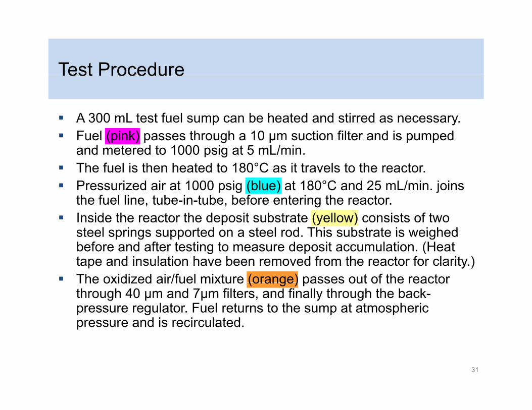

C t ill RiCaterpillar Rig
Data Presentation and CommentsNote Due to timing and internal organization fuels were tested in three stages each by a different team
Deposit Results ndash Substrate Depositsepos t esu ts Subst ate epos ts
Many but not all of the results were repeatable
025
03Team 1 - Substrate Deposits
0 1
015
02
epos
it M
ass
(g)
0
005
01De
34
Deposit Results ndash Substrate Depositsepos t esu ts Subst ate epos ts
Adding NaOH did not cause deposits in all fuels
0025
003Team 2 amp 3 - Substrate Deposits
001
0015
002
epos
it M
ass
(g)
0
0005
001
De
N tNotes The John Deere fuel test was shut down prior to completion due to excessive deposits clogging the system
The Cat Reference-3 test occurred after known system contamination The difference between this measurement and the other Cat Reference measurements is likely due to insufficient system decontamination
35
Deposit Results ndash Filter Depositsepos t esu ts te epos ts
Obvious differences from the substrate deposits
0 14
016
018
02Team 1 - Filter Deposits
008
01
012
014
epos
it M
ass
(g)
0
002
004
006De
36
Deposit Results ndash Filter Depositsepos t esu ts te epos ts
0025
003
)
Teams 2 amp 3 - Filter Deposits
001
0015
002
epos
it M
ass
(g)
0
0005
0 0
D
NotesNotes The John Deere fuel test was shut down prior to completion due to excessive deposits clogging the system
The Cat Reference-3 test occurred after known system contamination The difference between this measurement and the other Cat Reference measurements is likely due to insufficient system decontamination
37
Caterpillar Observations and ConclusionsCate p a Obse at o s a d Co c us o s
Substrate deposit mass and filter deposit mass are the primary metrics of fuel deposit propensitydeposit propensityThe system is sensitive to changes in the operation details
ndash Demonstrated difficulty in data repeatabilitybull Some data was repeatable but not all
The system history can impact datandash Tests run after known system contamination seemed to have unusually high amounts of
deposits
In many cases the amount of deposits generated was small enough toIn many cases the amount of deposits generated was small enough to challenge the detection limit of the balance used
ndash Test conditions should be optimized to produce more measurable results and more differentiation
The test rig may better represent some types of deposits than othersThe test rig may better represent some types of deposits than othersndash Oxidation-driven deposits are the prime target of the rig
5-hour test time may not be optimum for all fuelsndash Different fuels may experience a different amount of degradation in 5 hours
38
CAT CATERPILLAR their respective logos ldquoCaterpillar Yellowrdquo the ldquoPower Edgerdquo trade dress as well as corporate and productidentity used herein are trademarks of Caterpillar and may not be used without permission
copy2012 Caterpillar All Rights Reserved
C t ill RiCaterpillar Rig
More Formal Data AnalysisNote Due to timing and internal organization fuels were tested in three stages each by a different team
All Data ndash Trellised by Teamata e sed by ea
T i d d i d iTest terminated due to excessive deposits
40
Teams 2 and 3 ndash Trellised by Teamea s a d 3 e sed by ea
Test terminated due to excessive deposits
41
All Data ndash Trellised by Teamata e sed by ea
Test terminated due to excessive deposits
42
Teams 2 and 3 ndash Trellised by Teamea s a d 3 e sed by ea
Test terminated due to excessive deposits
43
I RiInnospec Rig
Methodologyet odo ogy
Injector rig conditions used for the program
Variable Setting
Injectors 4 new Bosch CRIN1 injectors per runper run
Filters 2 new Fleetguard FF167 filters per run
Pre-rig clean Repeat rinses with MeOH MEPP (Methoxy Propoxy Propanol) and test diesel
Run time 100 hours
Cycle Standard rig test cycle
Injector tip temperature 180ordmC
Fuel tank temperature 35ordmC
Fuel volume 32 litres
RPM flywheel 1200
45
Analysisa ys s
The following tests were carried out to measure deposition rates
Component Test Measurement Testing Details
Filter Insoluble Carbon Total carbon from both filters by TPO (microgcm-2)
Performed in triplicate on both filters from runy ( g )
See next page for definition of TPO
Injector Back Leakage Change in performance from new injector
Performed in duplicate on each injector
Injector Pressure Drop Change in performance from new injector
5 tests on each injector
I j t I j t Ti D it N li d bl k t d T t f d ll 4Injector Injector Tip Deposit Normalized blank corrected carbon deposit level by TPO
Test performed on all 4 injectors from run
Injector Injector Needle Deposit
Injector Injector Push Rod Deposit
46
Temperature Programmed Oxidation (TPO)e pe atu e og a ed O dat o ( O)
Sample is placed in a quartz sample boat and inserted into a temperature-controlled furnace where it is heated in a calibrated oxygen atmosphere Oxygen feed rate = 0 75 liters perOxygen feed rate 075 liters per minuteStarting temperature = 270degC For testing the temperature was increased to 700degC at a rate of 100degC per minute The CO2 resulting from the oxidation of the carbon is detected by calibrated IR detectorsdetectors Total carbon result calculated from amount of CO2 ndash can either be expressed per unit area (if known) or e p essed pe u t a ea ( o ) onormalized to a surface area = 1
47
I RiInnospec Rig
Data Presentation and Comments
Analysis ndash Insoluble Filter Depositsa ys s so ub e te epos ts
Both fuel tank filters removed and dismantled5 x 1 cm vertical sections removed for analysis from each filterEach section placed in 60 mLEach section placed in 60 mL tri-solvent (602020 toluene acetonemethanol) and placed in an ultrasonic bath for 30 minutesSolvent then filtered through 07-micron GF filter paperFilter paper rinsed with 2 x 25 mL washes of isooctane and dried atwashes of isooctane and dried at 100degC for 2 hoursTest performed in triplicate on both filters
49
CRC Testing ndash Filter DepositsC C est g te epos ts
Each GF filter paper run on RC612 TPO analyzer
Run Fuel Average Total Carbon Deposit (microgcm2)analyzer
Sample was run under ramp method from 270degC to 700degCTotal carbon calculated per unit area of original fuel tank filter paper (10 cm2)
Deposit (microgcm )
1 RNoDep 10837
2 RDep 8837
3 EPANoDep 16650original fuel tank filter paper (10 cm )Results quoted as average total carbon for both filters
p
4 EPADep 10360
5 R93 8013
6 HiSulf 6650
ObservationsHi Sulf R93 and CARB gave lowest resultsIncreased filter deposits observed in Runs 3 and 14 following NaOH-treated runs
f 2 d 13 ti l i
7 CARB 7343
8 CARB 7380
9 HiSulf 8127
of 2 and 13 ndash suggesting cleaning process not removing all NaOH as second run with same fuel gave appreciably different resultsVery good repeatability achieved with the exception of runs that followed NaOH
10 R93 6550
11 EPADep 8350
12 EPANoDep 9323
13 RDep 67 53exception of runs that followed NaOH addition (3 and 14)
13 RDep 6753
14 RNoDep 7377
50
Injector Testingjecto est g
Each injector removed from rig and mounted in DIT31 Injector TesterEach injector measured pre- and post-test for
Back leakagendash Back leakagendash Pressure drop
Result quoted is differencebetween pre- and post-testbetween pre and post test
51
CRC Testing ndash Back LeakageC C est g ac ea age
Test performed in duplicate on each of all 4 injectors Run Fuel Average Change
(Pre- to Post-Test)Secondsall 4 injectorsResults quoted are the average change for all injectors from each runInjector is pressurised to 1100 barAir supply is switched off and the pressure
(Pre- to Post-Test)Seconds
1 RNoDep -563
2 RDep -508
3 EPANoDep 185allowed to return to ambientBack leakage is quoted as the time taken to fall from 600 to 200 barThe faster the time the greater the likelihood of injector seal failure
p
4 EPADep -250
5 R93 401
6 HiSulf -318likelihood of injector seal failure The higher the negative value the greater the loss of performance
Observations
7 CARB -659
8 CARB -099
9 HiSulf -408
High degree of variability between batches of same fuelDifficult to quantify significant changes in performanceNot recommended as a performance
10 R93 -323
11 EPADep -154
12 EPANoDep -248
13 RDep -4 55Not recommended as a performance measurement
13 RDep -455
14 RNoDep -098
52
CRC Testing ndash Pressure DropC C est g essu e op
Test performed 5 times on each of all 4 injectors Run Fuel Average Change
(Pre- to Post-Test)BarinjectorsResults quoted are the average change for all injectors from each runInjector is pressurised to 1100 barAir supply is switched off and the pressure
(Pre- to Post-Test)Bar
1 RNoDep 015
2 RDep 280
3 EPANoDep 455pp y pallowed to return to ambientAt 750 bar the injector is fired for 8 msThe pressure drop during firing is measured in barA i ifi t f ll i d f t t t
p
4 EPADep 245
5 R93 400
6 HiSulf 470A significant fall in pressure drop from start to finish is indicative of deposit buildupAn significant increase in pressure drop could be indicative of injectorlsquostickingrsquo
C l i (t d t )
7 CARB 145
8 CARB -213
9 HiSulf 387
Conclusions (to date)High degree of variability between batches of same fuelDifficult to quantify significant changes in performance
10 R93 1030
11 EPADep -205
12 EPANoDep 245
13 RDep 0 95performanceNot recommended as a performance measurement
13 RDep 095
14 RNoDep 735
53
Injector Dismantlingjecto s a t g
All 4 injectors from each run dismantled3 t t i d f l i3 parts retained for analysis
ndash Tipndash Needlendash Pushrod
Parts rinsed in toluene then acetone then dried in oven for 2 hoursTPO analysis performed on all 4 injectors from each run ndashfinal result is average of 4 testsFi l d it l l l l t d b i b l lFinal deposit level calculated by measuring carbon levels and subtracting blank injector resultTip and needle analysis too variable ndash did not differentiate between fuels
54
CRC Testing ndash Injector TipC C est g jecto p
Run Fuel Average Total Carbon Deposit (microgcm2)
Each tip sectioned using diamond saw to allow testing of tip section exposed in rig Deposit (microgcm2)
1 RNoDep -598
2 RDep 467
3 EPANoDep -533
allow testing of tip section exposed in rigSample run on RC612 TPO analyzer from 270degC to 700degCEach test was baseline corrected against a new pushrod p
4 EPADep -698
5 R93 15785
6 HiSulf 333
new pushrodResults are based on a fixed surface area of 1 cm2
Conclusions (to date)7 CARB 1763
8 CARB -073
9 HiSulf -367
Conclusions (to date)Excess variability in results ndash most likely to be due to washing effect in post-injector drain (C of V typically gt100)Difficult to draw any conclusions ndash analysis
10 R93 6068
11 EPADep 3973
12 EPANoDep -280
13 RDep 30 10
y ynot satisfactory in current form Variation in test resulted in some totals being less than blank needleNot recommended as a performance
d i d b 13 RDep 3010
14 RNoDep 3045
55
measurement ndash drain needs to be redesigned
CRC Testing ndash Injector NeedleC C est g jecto eed e
Each needle sectioned using diamond saw to allow testing of needle section with no Run Fuel Average Total Carbon
Deposit (microgcm2)to allow testing of needle section with no DLC coatingSample run on RC612 TPO analyser from 270degC to 700degCEach test was baseline corrected against a
Deposit (microgcm2)
1 RNoDep -010
2 RDep 163
3 EPANoDep 283Each test was baseline corrected against a new pushrodResults are based on a fixed surface area of 1 cm2
p
4 EPADep 030
5 R93 133
6 HiSulf -143
Conclusions (to date)Excess variability in results ndash most likely to be due to minute levels of deposit on section (C of V typically gt100)
7 CARB 885
8 CARB 367
9 HiSulf 510
Difficult to draw any conclusions ndash analysis not satisfactory in current form Variation in test resulted in some totals being less than blank needleNot recommended as performance
10 R93 1453
11 EPADep 1333
12 EPANoDep 133
13 RDep 13 15Not recommended as performance measurement
13 RDep 1315
14 RNoDep 1478
56
CRC Testing ndash Injector Push RodC C est g jecto us od
Each pushrod run on RC612 TPO analyzer from 270degC to 700degC Run Fuel Average Total Carbon
Deposit (microgcm2)from 270 C to 700 CEach test was baseline corrected against a new pushrodResults are based on a fixed surface area of 1 cm2
Deposit (microgcm2)
1 RNoDep 1620
2 RDep 1538
3 EPANoDep 1735p
4 EPADep 1103
5 R93 1187
6 HiSulf 900
ConclusionsAll fuels created deposits on the pushrodVery good repeatability achieved with the
7 CARB 1863
8 CARB 1590
9 HiSulf 1098Very good repeatability achieved with the exception of Runs 3 and 14 that followed NaOH addition Runs 2 and 13EPADep and HiSulf gave lowest resultsRNoDep gave highest results but this may be skewed by previous run
10 R93 1493
11 EPADep 1215
12 EPANoDep 1220
13 RDep 14 10be skewed by previous runTest appears to differentiate between fuels
13 RDep 1410
14 RNoDep 3548
57
Innospec Rig Summary ndash Prorsquosospec g Su a y o s
Two tests identified as showing differentiation between fuels with good repeatability
ndash Total insoluble carbon from post-tank filtersndash Carbon deposit level on injector pushrod
Rig config ration no reliable no breakdo ns d ring testingRig configuration now reliable ndash no breakdowns during testingRig uses real engine parts filters common rail pump and injectorsRig set up as close as possible to engine test without combustionRi h th t ti l t t f di l i j t ld h t bRig has the potential to use any type of diesel injector ndash would have to be discussed with manufacturer
58
Innospec Rig Summary ndash Conrsquosospec g Su a y Co s
Equipment costly to install Initially rig ~$100K TPO analyzer $70KRig adapted in-house since purchase to include injector heaters and extraction cabinetEquipment manufacturer relatively small company ndash limited supportTest is costly ndash $2K for injectors and filters per test 3 man-days (cost = )Test is costly $2K for injectors and filters per test 3 man days (cost ) required per test including analysis (not including periodic monitoring during test) Test takes 100 hours analysis ~8 hoursO i ht i i d t t it d d i i ht iOvernight running required ndash test monitored during night runningCleaning step is potentially hazardous time consuming and unsuitable for a bench rig ndash up to 75 liters of solvent and fuel required (in total for cleaning)g)Running NaOH in rig may have adversely affected subsequent runsRig conditions may not be severe enough to establish clear differences between fuelsFurther work may be required to improve injector drainage systemFurther work may be required to improve injector drainage systemFor true correlation test would have to be run against actual engine data
59
I RiInnospec Rig
More Formal Data Analysis
Filters Average Total Insoluble Carbon Deposit (microgcmsup2)
61
Filters Average Total Insoluble Carbon Deposit (microgcmsup2)
Pairs of fuel with overlapping intervals were not significantly (α=005) different from each other
62
Filters Average Total Insoluble Carbon Deposit (microgcmsup2)
resi
dual
sud
entiz
ed
Stu
63
Injector Pushrod TPO Carbon Deposit (microgcmsup2)
64
IPRAvg = average of four injectors IPROSA = outlier screened average
Injector Pushrod TPO Carbon Deposit (microgcmsup2)
Outlier Screened AverageOutlier Screened Average
Pairs of fuel with overlapping intervals were not significantly (α=005) different from each other
65
Outlier Screened Average
Injector Pushrod TPO Carbon Deposit (microgcmsup2)
Outlier Screened Averagere
sidu
als
uden
tized
S
tu
66
ConclusionsCo c us o s
Results from this scoping study did not confirm that p g yeither one of these rigs in their present state could discriminate among deposit forming and not deposit forming fuelsforming fuelsIf in-house work by either sponsor results in changes to provide differentiation CRC will consider further evaluationA new rig offered by Delphi is being considered
67

Deposit Results ndash Substrate Depositsepos t esu ts Subst ate epos ts
Adding NaOH did not cause deposits in all fuels
0025
003Team 2 amp 3 - Substrate Deposits
001
0015
002
epos
it M
ass
(g)
0
0005
001
De
N tNotes The John Deere fuel test was shut down prior to completion due to excessive deposits clogging the system
The Cat Reference-3 test occurred after known system contamination The difference between this measurement and the other Cat Reference measurements is likely due to insufficient system decontamination
35
Deposit Results ndash Filter Depositsepos t esu ts te epos ts
Obvious differences from the substrate deposits
0 14
016
018
02Team 1 - Filter Deposits
008
01
012
014
epos
it M
ass
(g)
0
002
004
006De
36
Deposit Results ndash Filter Depositsepos t esu ts te epos ts
0025
003
)
Teams 2 amp 3 - Filter Deposits
001
0015
002
epos
it M
ass
(g)
0
0005
0 0
D
NotesNotes The John Deere fuel test was shut down prior to completion due to excessive deposits clogging the system
The Cat Reference-3 test occurred after known system contamination The difference between this measurement and the other Cat Reference measurements is likely due to insufficient system decontamination
37
Caterpillar Observations and ConclusionsCate p a Obse at o s a d Co c us o s
Substrate deposit mass and filter deposit mass are the primary metrics of fuel deposit propensitydeposit propensityThe system is sensitive to changes in the operation details
ndash Demonstrated difficulty in data repeatabilitybull Some data was repeatable but not all
The system history can impact datandash Tests run after known system contamination seemed to have unusually high amounts of
deposits
In many cases the amount of deposits generated was small enough toIn many cases the amount of deposits generated was small enough to challenge the detection limit of the balance used
ndash Test conditions should be optimized to produce more measurable results and more differentiation
The test rig may better represent some types of deposits than othersThe test rig may better represent some types of deposits than othersndash Oxidation-driven deposits are the prime target of the rig
5-hour test time may not be optimum for all fuelsndash Different fuels may experience a different amount of degradation in 5 hours
38
CAT CATERPILLAR their respective logos ldquoCaterpillar Yellowrdquo the ldquoPower Edgerdquo trade dress as well as corporate and productidentity used herein are trademarks of Caterpillar and may not be used without permission
copy2012 Caterpillar All Rights Reserved
C t ill RiCaterpillar Rig
More Formal Data AnalysisNote Due to timing and internal organization fuels were tested in three stages each by a different team
All Data ndash Trellised by Teamata e sed by ea
T i d d i d iTest terminated due to excessive deposits
40
Teams 2 and 3 ndash Trellised by Teamea s a d 3 e sed by ea
Test terminated due to excessive deposits
41
All Data ndash Trellised by Teamata e sed by ea
Test terminated due to excessive deposits
42
Teams 2 and 3 ndash Trellised by Teamea s a d 3 e sed by ea
Test terminated due to excessive deposits
43
I RiInnospec Rig
Methodologyet odo ogy
Injector rig conditions used for the program
Variable Setting
Injectors 4 new Bosch CRIN1 injectors per runper run
Filters 2 new Fleetguard FF167 filters per run
Pre-rig clean Repeat rinses with MeOH MEPP (Methoxy Propoxy Propanol) and test diesel
Run time 100 hours
Cycle Standard rig test cycle
Injector tip temperature 180ordmC
Fuel tank temperature 35ordmC
Fuel volume 32 litres
RPM flywheel 1200
45
Analysisa ys s
The following tests were carried out to measure deposition rates
Component Test Measurement Testing Details
Filter Insoluble Carbon Total carbon from both filters by TPO (microgcm-2)
Performed in triplicate on both filters from runy ( g )
See next page for definition of TPO
Injector Back Leakage Change in performance from new injector
Performed in duplicate on each injector
Injector Pressure Drop Change in performance from new injector
5 tests on each injector
I j t I j t Ti D it N li d bl k t d T t f d ll 4Injector Injector Tip Deposit Normalized blank corrected carbon deposit level by TPO
Test performed on all 4 injectors from run
Injector Injector Needle Deposit
Injector Injector Push Rod Deposit
46
Temperature Programmed Oxidation (TPO)e pe atu e og a ed O dat o ( O)
Sample is placed in a quartz sample boat and inserted into a temperature-controlled furnace where it is heated in a calibrated oxygen atmosphere Oxygen feed rate = 0 75 liters perOxygen feed rate 075 liters per minuteStarting temperature = 270degC For testing the temperature was increased to 700degC at a rate of 100degC per minute The CO2 resulting from the oxidation of the carbon is detected by calibrated IR detectorsdetectors Total carbon result calculated from amount of CO2 ndash can either be expressed per unit area (if known) or e p essed pe u t a ea ( o ) onormalized to a surface area = 1
47
I RiInnospec Rig
Data Presentation and Comments
Analysis ndash Insoluble Filter Depositsa ys s so ub e te epos ts
Both fuel tank filters removed and dismantled5 x 1 cm vertical sections removed for analysis from each filterEach section placed in 60 mLEach section placed in 60 mL tri-solvent (602020 toluene acetonemethanol) and placed in an ultrasonic bath for 30 minutesSolvent then filtered through 07-micron GF filter paperFilter paper rinsed with 2 x 25 mL washes of isooctane and dried atwashes of isooctane and dried at 100degC for 2 hoursTest performed in triplicate on both filters
49
CRC Testing ndash Filter DepositsC C est g te epos ts
Each GF filter paper run on RC612 TPO analyzer
Run Fuel Average Total Carbon Deposit (microgcm2)analyzer
Sample was run under ramp method from 270degC to 700degCTotal carbon calculated per unit area of original fuel tank filter paper (10 cm2)
Deposit (microgcm )
1 RNoDep 10837
2 RDep 8837
3 EPANoDep 16650original fuel tank filter paper (10 cm )Results quoted as average total carbon for both filters
p
4 EPADep 10360
5 R93 8013
6 HiSulf 6650
ObservationsHi Sulf R93 and CARB gave lowest resultsIncreased filter deposits observed in Runs 3 and 14 following NaOH-treated runs
f 2 d 13 ti l i
7 CARB 7343
8 CARB 7380
9 HiSulf 8127
of 2 and 13 ndash suggesting cleaning process not removing all NaOH as second run with same fuel gave appreciably different resultsVery good repeatability achieved with the exception of runs that followed NaOH
10 R93 6550
11 EPADep 8350
12 EPANoDep 9323
13 RDep 67 53exception of runs that followed NaOH addition (3 and 14)
13 RDep 6753
14 RNoDep 7377
50
Injector Testingjecto est g
Each injector removed from rig and mounted in DIT31 Injector TesterEach injector measured pre- and post-test for
Back leakagendash Back leakagendash Pressure drop
Result quoted is differencebetween pre- and post-testbetween pre and post test
51
CRC Testing ndash Back LeakageC C est g ac ea age
Test performed in duplicate on each of all 4 injectors Run Fuel Average Change
(Pre- to Post-Test)Secondsall 4 injectorsResults quoted are the average change for all injectors from each runInjector is pressurised to 1100 barAir supply is switched off and the pressure
(Pre- to Post-Test)Seconds
1 RNoDep -563
2 RDep -508
3 EPANoDep 185allowed to return to ambientBack leakage is quoted as the time taken to fall from 600 to 200 barThe faster the time the greater the likelihood of injector seal failure
p
4 EPADep -250
5 R93 401
6 HiSulf -318likelihood of injector seal failure The higher the negative value the greater the loss of performance
Observations
7 CARB -659
8 CARB -099
9 HiSulf -408
High degree of variability between batches of same fuelDifficult to quantify significant changes in performanceNot recommended as a performance
10 R93 -323
11 EPADep -154
12 EPANoDep -248
13 RDep -4 55Not recommended as a performance measurement
13 RDep -455
14 RNoDep -098
52
CRC Testing ndash Pressure DropC C est g essu e op
Test performed 5 times on each of all 4 injectors Run Fuel Average Change
(Pre- to Post-Test)BarinjectorsResults quoted are the average change for all injectors from each runInjector is pressurised to 1100 barAir supply is switched off and the pressure
(Pre- to Post-Test)Bar
1 RNoDep 015
2 RDep 280
3 EPANoDep 455pp y pallowed to return to ambientAt 750 bar the injector is fired for 8 msThe pressure drop during firing is measured in barA i ifi t f ll i d f t t t
p
4 EPADep 245
5 R93 400
6 HiSulf 470A significant fall in pressure drop from start to finish is indicative of deposit buildupAn significant increase in pressure drop could be indicative of injectorlsquostickingrsquo
C l i (t d t )
7 CARB 145
8 CARB -213
9 HiSulf 387
Conclusions (to date)High degree of variability between batches of same fuelDifficult to quantify significant changes in performance
10 R93 1030
11 EPADep -205
12 EPANoDep 245
13 RDep 0 95performanceNot recommended as a performance measurement
13 RDep 095
14 RNoDep 735
53
Injector Dismantlingjecto s a t g
All 4 injectors from each run dismantled3 t t i d f l i3 parts retained for analysis
ndash Tipndash Needlendash Pushrod
Parts rinsed in toluene then acetone then dried in oven for 2 hoursTPO analysis performed on all 4 injectors from each run ndashfinal result is average of 4 testsFi l d it l l l l t d b i b l lFinal deposit level calculated by measuring carbon levels and subtracting blank injector resultTip and needle analysis too variable ndash did not differentiate between fuels
54
CRC Testing ndash Injector TipC C est g jecto p
Run Fuel Average Total Carbon Deposit (microgcm2)
Each tip sectioned using diamond saw to allow testing of tip section exposed in rig Deposit (microgcm2)
1 RNoDep -598
2 RDep 467
3 EPANoDep -533
allow testing of tip section exposed in rigSample run on RC612 TPO analyzer from 270degC to 700degCEach test was baseline corrected against a new pushrod p
4 EPADep -698
5 R93 15785
6 HiSulf 333
new pushrodResults are based on a fixed surface area of 1 cm2
Conclusions (to date)7 CARB 1763
8 CARB -073
9 HiSulf -367
Conclusions (to date)Excess variability in results ndash most likely to be due to washing effect in post-injector drain (C of V typically gt100)Difficult to draw any conclusions ndash analysis
10 R93 6068
11 EPADep 3973
12 EPANoDep -280
13 RDep 30 10
y ynot satisfactory in current form Variation in test resulted in some totals being less than blank needleNot recommended as a performance
d i d b 13 RDep 3010
14 RNoDep 3045
55
measurement ndash drain needs to be redesigned
CRC Testing ndash Injector NeedleC C est g jecto eed e
Each needle sectioned using diamond saw to allow testing of needle section with no Run Fuel Average Total Carbon
Deposit (microgcm2)to allow testing of needle section with no DLC coatingSample run on RC612 TPO analyser from 270degC to 700degCEach test was baseline corrected against a
Deposit (microgcm2)
1 RNoDep -010
2 RDep 163
3 EPANoDep 283Each test was baseline corrected against a new pushrodResults are based on a fixed surface area of 1 cm2
p
4 EPADep 030
5 R93 133
6 HiSulf -143
Conclusions (to date)Excess variability in results ndash most likely to be due to minute levels of deposit on section (C of V typically gt100)
7 CARB 885
8 CARB 367
9 HiSulf 510
Difficult to draw any conclusions ndash analysis not satisfactory in current form Variation in test resulted in some totals being less than blank needleNot recommended as performance
10 R93 1453
11 EPADep 1333
12 EPANoDep 133
13 RDep 13 15Not recommended as performance measurement
13 RDep 1315
14 RNoDep 1478
56
CRC Testing ndash Injector Push RodC C est g jecto us od
Each pushrod run on RC612 TPO analyzer from 270degC to 700degC Run Fuel Average Total Carbon
Deposit (microgcm2)from 270 C to 700 CEach test was baseline corrected against a new pushrodResults are based on a fixed surface area of 1 cm2
Deposit (microgcm2)
1 RNoDep 1620
2 RDep 1538
3 EPANoDep 1735p
4 EPADep 1103
5 R93 1187
6 HiSulf 900
ConclusionsAll fuels created deposits on the pushrodVery good repeatability achieved with the
7 CARB 1863
8 CARB 1590
9 HiSulf 1098Very good repeatability achieved with the exception of Runs 3 and 14 that followed NaOH addition Runs 2 and 13EPADep and HiSulf gave lowest resultsRNoDep gave highest results but this may be skewed by previous run
10 R93 1493
11 EPADep 1215
12 EPANoDep 1220
13 RDep 14 10be skewed by previous runTest appears to differentiate between fuels
13 RDep 1410
14 RNoDep 3548
57
Innospec Rig Summary ndash Prorsquosospec g Su a y o s
Two tests identified as showing differentiation between fuels with good repeatability
ndash Total insoluble carbon from post-tank filtersndash Carbon deposit level on injector pushrod
Rig config ration no reliable no breakdo ns d ring testingRig configuration now reliable ndash no breakdowns during testingRig uses real engine parts filters common rail pump and injectorsRig set up as close as possible to engine test without combustionRi h th t ti l t t f di l i j t ld h t bRig has the potential to use any type of diesel injector ndash would have to be discussed with manufacturer
58
Innospec Rig Summary ndash Conrsquosospec g Su a y Co s
Equipment costly to install Initially rig ~$100K TPO analyzer $70KRig adapted in-house since purchase to include injector heaters and extraction cabinetEquipment manufacturer relatively small company ndash limited supportTest is costly ndash $2K for injectors and filters per test 3 man-days (cost = )Test is costly $2K for injectors and filters per test 3 man days (cost ) required per test including analysis (not including periodic monitoring during test) Test takes 100 hours analysis ~8 hoursO i ht i i d t t it d d i i ht iOvernight running required ndash test monitored during night runningCleaning step is potentially hazardous time consuming and unsuitable for a bench rig ndash up to 75 liters of solvent and fuel required (in total for cleaning)g)Running NaOH in rig may have adversely affected subsequent runsRig conditions may not be severe enough to establish clear differences between fuelsFurther work may be required to improve injector drainage systemFurther work may be required to improve injector drainage systemFor true correlation test would have to be run against actual engine data
59
I RiInnospec Rig
More Formal Data Analysis
Filters Average Total Insoluble Carbon Deposit (microgcmsup2)
61
Filters Average Total Insoluble Carbon Deposit (microgcmsup2)
Pairs of fuel with overlapping intervals were not significantly (α=005) different from each other
62
Filters Average Total Insoluble Carbon Deposit (microgcmsup2)
resi
dual
sud
entiz
ed
Stu
63
Injector Pushrod TPO Carbon Deposit (microgcmsup2)
64
IPRAvg = average of four injectors IPROSA = outlier screened average
Injector Pushrod TPO Carbon Deposit (microgcmsup2)
Outlier Screened AverageOutlier Screened Average
Pairs of fuel with overlapping intervals were not significantly (α=005) different from each other
65
Outlier Screened Average
Injector Pushrod TPO Carbon Deposit (microgcmsup2)
Outlier Screened Averagere
sidu
als
uden
tized
S
tu
66
ConclusionsCo c us o s
Results from this scoping study did not confirm that p g yeither one of these rigs in their present state could discriminate among deposit forming and not deposit forming fuelsforming fuelsIf in-house work by either sponsor results in changes to provide differentiation CRC will consider further evaluationA new rig offered by Delphi is being considered
67

Deposit Results ndash Filter Depositsepos t esu ts te epos ts
0025
003
)
Teams 2 amp 3 - Filter Deposits
001
0015
002
epos
it M
ass
(g)
0
0005
0 0
D
NotesNotes The John Deere fuel test was shut down prior to completion due to excessive deposits clogging the system
The Cat Reference-3 test occurred after known system contamination The difference between this measurement and the other Cat Reference measurements is likely due to insufficient system decontamination
37
Caterpillar Observations and ConclusionsCate p a Obse at o s a d Co c us o s
Substrate deposit mass and filter deposit mass are the primary metrics of fuel deposit propensitydeposit propensityThe system is sensitive to changes in the operation details
ndash Demonstrated difficulty in data repeatabilitybull Some data was repeatable but not all
The system history can impact datandash Tests run after known system contamination seemed to have unusually high amounts of
deposits
In many cases the amount of deposits generated was small enough toIn many cases the amount of deposits generated was small enough to challenge the detection limit of the balance used
ndash Test conditions should be optimized to produce more measurable results and more differentiation
The test rig may better represent some types of deposits than othersThe test rig may better represent some types of deposits than othersndash Oxidation-driven deposits are the prime target of the rig
5-hour test time may not be optimum for all fuelsndash Different fuels may experience a different amount of degradation in 5 hours
38
CAT CATERPILLAR their respective logos ldquoCaterpillar Yellowrdquo the ldquoPower Edgerdquo trade dress as well as corporate and productidentity used herein are trademarks of Caterpillar and may not be used without permission
copy2012 Caterpillar All Rights Reserved
C t ill RiCaterpillar Rig
More Formal Data AnalysisNote Due to timing and internal organization fuels were tested in three stages each by a different team
All Data ndash Trellised by Teamata e sed by ea
T i d d i d iTest terminated due to excessive deposits
40
Teams 2 and 3 ndash Trellised by Teamea s a d 3 e sed by ea
Test terminated due to excessive deposits
41
All Data ndash Trellised by Teamata e sed by ea
Test terminated due to excessive deposits
42
Teams 2 and 3 ndash Trellised by Teamea s a d 3 e sed by ea
Test terminated due to excessive deposits
43
I RiInnospec Rig
Methodologyet odo ogy
Injector rig conditions used for the program
Variable Setting
Injectors 4 new Bosch CRIN1 injectors per runper run
Filters 2 new Fleetguard FF167 filters per run
Pre-rig clean Repeat rinses with MeOH MEPP (Methoxy Propoxy Propanol) and test diesel
Run time 100 hours
Cycle Standard rig test cycle
Injector tip temperature 180ordmC
Fuel tank temperature 35ordmC
Fuel volume 32 litres
RPM flywheel 1200
45
Analysisa ys s
The following tests were carried out to measure deposition rates
Component Test Measurement Testing Details
Filter Insoluble Carbon Total carbon from both filters by TPO (microgcm-2)
Performed in triplicate on both filters from runy ( g )
See next page for definition of TPO
Injector Back Leakage Change in performance from new injector
Performed in duplicate on each injector
Injector Pressure Drop Change in performance from new injector
5 tests on each injector
I j t I j t Ti D it N li d bl k t d T t f d ll 4Injector Injector Tip Deposit Normalized blank corrected carbon deposit level by TPO
Test performed on all 4 injectors from run
Injector Injector Needle Deposit
Injector Injector Push Rod Deposit
46
Temperature Programmed Oxidation (TPO)e pe atu e og a ed O dat o ( O)
Sample is placed in a quartz sample boat and inserted into a temperature-controlled furnace where it is heated in a calibrated oxygen atmosphere Oxygen feed rate = 0 75 liters perOxygen feed rate 075 liters per minuteStarting temperature = 270degC For testing the temperature was increased to 700degC at a rate of 100degC per minute The CO2 resulting from the oxidation of the carbon is detected by calibrated IR detectorsdetectors Total carbon result calculated from amount of CO2 ndash can either be expressed per unit area (if known) or e p essed pe u t a ea ( o ) onormalized to a surface area = 1
47
I RiInnospec Rig
Data Presentation and Comments
Analysis ndash Insoluble Filter Depositsa ys s so ub e te epos ts
Both fuel tank filters removed and dismantled5 x 1 cm vertical sections removed for analysis from each filterEach section placed in 60 mLEach section placed in 60 mL tri-solvent (602020 toluene acetonemethanol) and placed in an ultrasonic bath for 30 minutesSolvent then filtered through 07-micron GF filter paperFilter paper rinsed with 2 x 25 mL washes of isooctane and dried atwashes of isooctane and dried at 100degC for 2 hoursTest performed in triplicate on both filters
49
CRC Testing ndash Filter DepositsC C est g te epos ts
Each GF filter paper run on RC612 TPO analyzer
Run Fuel Average Total Carbon Deposit (microgcm2)analyzer
Sample was run under ramp method from 270degC to 700degCTotal carbon calculated per unit area of original fuel tank filter paper (10 cm2)
Deposit (microgcm )
1 RNoDep 10837
2 RDep 8837
3 EPANoDep 16650original fuel tank filter paper (10 cm )Results quoted as average total carbon for both filters
p
4 EPADep 10360
5 R93 8013
6 HiSulf 6650
ObservationsHi Sulf R93 and CARB gave lowest resultsIncreased filter deposits observed in Runs 3 and 14 following NaOH-treated runs
f 2 d 13 ti l i
7 CARB 7343
8 CARB 7380
9 HiSulf 8127
of 2 and 13 ndash suggesting cleaning process not removing all NaOH as second run with same fuel gave appreciably different resultsVery good repeatability achieved with the exception of runs that followed NaOH
10 R93 6550
11 EPADep 8350
12 EPANoDep 9323
13 RDep 67 53exception of runs that followed NaOH addition (3 and 14)
13 RDep 6753
14 RNoDep 7377
50
Injector Testingjecto est g
Each injector removed from rig and mounted in DIT31 Injector TesterEach injector measured pre- and post-test for
Back leakagendash Back leakagendash Pressure drop
Result quoted is differencebetween pre- and post-testbetween pre and post test
51
CRC Testing ndash Back LeakageC C est g ac ea age
Test performed in duplicate on each of all 4 injectors Run Fuel Average Change
(Pre- to Post-Test)Secondsall 4 injectorsResults quoted are the average change for all injectors from each runInjector is pressurised to 1100 barAir supply is switched off and the pressure
(Pre- to Post-Test)Seconds
1 RNoDep -563
2 RDep -508
3 EPANoDep 185allowed to return to ambientBack leakage is quoted as the time taken to fall from 600 to 200 barThe faster the time the greater the likelihood of injector seal failure
p
4 EPADep -250
5 R93 401
6 HiSulf -318likelihood of injector seal failure The higher the negative value the greater the loss of performance
Observations
7 CARB -659
8 CARB -099
9 HiSulf -408
High degree of variability between batches of same fuelDifficult to quantify significant changes in performanceNot recommended as a performance
10 R93 -323
11 EPADep -154
12 EPANoDep -248
13 RDep -4 55Not recommended as a performance measurement
13 RDep -455
14 RNoDep -098
52
CRC Testing ndash Pressure DropC C est g essu e op
Test performed 5 times on each of all 4 injectors Run Fuel Average Change
(Pre- to Post-Test)BarinjectorsResults quoted are the average change for all injectors from each runInjector is pressurised to 1100 barAir supply is switched off and the pressure
(Pre- to Post-Test)Bar
1 RNoDep 015
2 RDep 280
3 EPANoDep 455pp y pallowed to return to ambientAt 750 bar the injector is fired for 8 msThe pressure drop during firing is measured in barA i ifi t f ll i d f t t t
p
4 EPADep 245
5 R93 400
6 HiSulf 470A significant fall in pressure drop from start to finish is indicative of deposit buildupAn significant increase in pressure drop could be indicative of injectorlsquostickingrsquo
C l i (t d t )
7 CARB 145
8 CARB -213
9 HiSulf 387
Conclusions (to date)High degree of variability between batches of same fuelDifficult to quantify significant changes in performance
10 R93 1030
11 EPADep -205
12 EPANoDep 245
13 RDep 0 95performanceNot recommended as a performance measurement
13 RDep 095
14 RNoDep 735
53
Injector Dismantlingjecto s a t g
All 4 injectors from each run dismantled3 t t i d f l i3 parts retained for analysis
ndash Tipndash Needlendash Pushrod
Parts rinsed in toluene then acetone then dried in oven for 2 hoursTPO analysis performed on all 4 injectors from each run ndashfinal result is average of 4 testsFi l d it l l l l t d b i b l lFinal deposit level calculated by measuring carbon levels and subtracting blank injector resultTip and needle analysis too variable ndash did not differentiate between fuels
54
CRC Testing ndash Injector TipC C est g jecto p
Run Fuel Average Total Carbon Deposit (microgcm2)
Each tip sectioned using diamond saw to allow testing of tip section exposed in rig Deposit (microgcm2)
1 RNoDep -598
2 RDep 467
3 EPANoDep -533
allow testing of tip section exposed in rigSample run on RC612 TPO analyzer from 270degC to 700degCEach test was baseline corrected against a new pushrod p
4 EPADep -698
5 R93 15785
6 HiSulf 333
new pushrodResults are based on a fixed surface area of 1 cm2
Conclusions (to date)7 CARB 1763
8 CARB -073
9 HiSulf -367
Conclusions (to date)Excess variability in results ndash most likely to be due to washing effect in post-injector drain (C of V typically gt100)Difficult to draw any conclusions ndash analysis
10 R93 6068
11 EPADep 3973
12 EPANoDep -280
13 RDep 30 10
y ynot satisfactory in current form Variation in test resulted in some totals being less than blank needleNot recommended as a performance
d i d b 13 RDep 3010
14 RNoDep 3045
55
measurement ndash drain needs to be redesigned
CRC Testing ndash Injector NeedleC C est g jecto eed e
Each needle sectioned using diamond saw to allow testing of needle section with no Run Fuel Average Total Carbon
Deposit (microgcm2)to allow testing of needle section with no DLC coatingSample run on RC612 TPO analyser from 270degC to 700degCEach test was baseline corrected against a
Deposit (microgcm2)
1 RNoDep -010
2 RDep 163
3 EPANoDep 283Each test was baseline corrected against a new pushrodResults are based on a fixed surface area of 1 cm2
p
4 EPADep 030
5 R93 133
6 HiSulf -143
Conclusions (to date)Excess variability in results ndash most likely to be due to minute levels of deposit on section (C of V typically gt100)
7 CARB 885
8 CARB 367
9 HiSulf 510
Difficult to draw any conclusions ndash analysis not satisfactory in current form Variation in test resulted in some totals being less than blank needleNot recommended as performance
10 R93 1453
11 EPADep 1333
12 EPANoDep 133
13 RDep 13 15Not recommended as performance measurement
13 RDep 1315
14 RNoDep 1478
56
CRC Testing ndash Injector Push RodC C est g jecto us od
Each pushrod run on RC612 TPO analyzer from 270degC to 700degC Run Fuel Average Total Carbon
Deposit (microgcm2)from 270 C to 700 CEach test was baseline corrected against a new pushrodResults are based on a fixed surface area of 1 cm2
Deposit (microgcm2)
1 RNoDep 1620
2 RDep 1538
3 EPANoDep 1735p
4 EPADep 1103
5 R93 1187
6 HiSulf 900
ConclusionsAll fuels created deposits on the pushrodVery good repeatability achieved with the
7 CARB 1863
8 CARB 1590
9 HiSulf 1098Very good repeatability achieved with the exception of Runs 3 and 14 that followed NaOH addition Runs 2 and 13EPADep and HiSulf gave lowest resultsRNoDep gave highest results but this may be skewed by previous run
10 R93 1493
11 EPADep 1215
12 EPANoDep 1220
13 RDep 14 10be skewed by previous runTest appears to differentiate between fuels
13 RDep 1410
14 RNoDep 3548
57
Innospec Rig Summary ndash Prorsquosospec g Su a y o s
Two tests identified as showing differentiation between fuels with good repeatability
ndash Total insoluble carbon from post-tank filtersndash Carbon deposit level on injector pushrod
Rig config ration no reliable no breakdo ns d ring testingRig configuration now reliable ndash no breakdowns during testingRig uses real engine parts filters common rail pump and injectorsRig set up as close as possible to engine test without combustionRi h th t ti l t t f di l i j t ld h t bRig has the potential to use any type of diesel injector ndash would have to be discussed with manufacturer
58
Innospec Rig Summary ndash Conrsquosospec g Su a y Co s
Equipment costly to install Initially rig ~$100K TPO analyzer $70KRig adapted in-house since purchase to include injector heaters and extraction cabinetEquipment manufacturer relatively small company ndash limited supportTest is costly ndash $2K for injectors and filters per test 3 man-days (cost = )Test is costly $2K for injectors and filters per test 3 man days (cost ) required per test including analysis (not including periodic monitoring during test) Test takes 100 hours analysis ~8 hoursO i ht i i d t t it d d i i ht iOvernight running required ndash test monitored during night runningCleaning step is potentially hazardous time consuming and unsuitable for a bench rig ndash up to 75 liters of solvent and fuel required (in total for cleaning)g)Running NaOH in rig may have adversely affected subsequent runsRig conditions may not be severe enough to establish clear differences between fuelsFurther work may be required to improve injector drainage systemFurther work may be required to improve injector drainage systemFor true correlation test would have to be run against actual engine data
59
I RiInnospec Rig
More Formal Data Analysis
Filters Average Total Insoluble Carbon Deposit (microgcmsup2)
61
Filters Average Total Insoluble Carbon Deposit (microgcmsup2)
Pairs of fuel with overlapping intervals were not significantly (α=005) different from each other
62
Filters Average Total Insoluble Carbon Deposit (microgcmsup2)
resi
dual
sud
entiz
ed
Stu
63
Injector Pushrod TPO Carbon Deposit (microgcmsup2)
64
IPRAvg = average of four injectors IPROSA = outlier screened average
Injector Pushrod TPO Carbon Deposit (microgcmsup2)
Outlier Screened AverageOutlier Screened Average
Pairs of fuel with overlapping intervals were not significantly (α=005) different from each other
65
Outlier Screened Average
Injector Pushrod TPO Carbon Deposit (microgcmsup2)
Outlier Screened Averagere
sidu
als
uden
tized
S
tu
66
ConclusionsCo c us o s
Results from this scoping study did not confirm that p g yeither one of these rigs in their present state could discriminate among deposit forming and not deposit forming fuelsforming fuelsIf in-house work by either sponsor results in changes to provide differentiation CRC will consider further evaluationA new rig offered by Delphi is being considered
67

All Data ndash Trellised by Teamata e sed by ea
T i d d i d iTest terminated due to excessive deposits
40
Teams 2 and 3 ndash Trellised by Teamea s a d 3 e sed by ea
Test terminated due to excessive deposits
41
All Data ndash Trellised by Teamata e sed by ea
Test terminated due to excessive deposits
42
Teams 2 and 3 ndash Trellised by Teamea s a d 3 e sed by ea
Test terminated due to excessive deposits
43
I RiInnospec Rig
Methodologyet odo ogy
Injector rig conditions used for the program
Variable Setting
Injectors 4 new Bosch CRIN1 injectors per runper run
Filters 2 new Fleetguard FF167 filters per run
Pre-rig clean Repeat rinses with MeOH MEPP (Methoxy Propoxy Propanol) and test diesel
Run time 100 hours
Cycle Standard rig test cycle
Injector tip temperature 180ordmC
Fuel tank temperature 35ordmC
Fuel volume 32 litres
RPM flywheel 1200
45
Analysisa ys s
The following tests were carried out to measure deposition rates
Component Test Measurement Testing Details
Filter Insoluble Carbon Total carbon from both filters by TPO (microgcm-2)
Performed in triplicate on both filters from runy ( g )
See next page for definition of TPO
Injector Back Leakage Change in performance from new injector
Performed in duplicate on each injector
Injector Pressure Drop Change in performance from new injector
5 tests on each injector
I j t I j t Ti D it N li d bl k t d T t f d ll 4Injector Injector Tip Deposit Normalized blank corrected carbon deposit level by TPO
Test performed on all 4 injectors from run
Injector Injector Needle Deposit
Injector Injector Push Rod Deposit
46
Temperature Programmed Oxidation (TPO)e pe atu e og a ed O dat o ( O)
Sample is placed in a quartz sample boat and inserted into a temperature-controlled furnace where it is heated in a calibrated oxygen atmosphere Oxygen feed rate = 0 75 liters perOxygen feed rate 075 liters per minuteStarting temperature = 270degC For testing the temperature was increased to 700degC at a rate of 100degC per minute The CO2 resulting from the oxidation of the carbon is detected by calibrated IR detectorsdetectors Total carbon result calculated from amount of CO2 ndash can either be expressed per unit area (if known) or e p essed pe u t a ea ( o ) onormalized to a surface area = 1
47
I RiInnospec Rig
Data Presentation and Comments
Analysis ndash Insoluble Filter Depositsa ys s so ub e te epos ts
Both fuel tank filters removed and dismantled5 x 1 cm vertical sections removed for analysis from each filterEach section placed in 60 mLEach section placed in 60 mL tri-solvent (602020 toluene acetonemethanol) and placed in an ultrasonic bath for 30 minutesSolvent then filtered through 07-micron GF filter paperFilter paper rinsed with 2 x 25 mL washes of isooctane and dried atwashes of isooctane and dried at 100degC for 2 hoursTest performed in triplicate on both filters
49
CRC Testing ndash Filter DepositsC C est g te epos ts
Each GF filter paper run on RC612 TPO analyzer
Run Fuel Average Total Carbon Deposit (microgcm2)analyzer
Sample was run under ramp method from 270degC to 700degCTotal carbon calculated per unit area of original fuel tank filter paper (10 cm2)
Deposit (microgcm )
1 RNoDep 10837
2 RDep 8837
3 EPANoDep 16650original fuel tank filter paper (10 cm )Results quoted as average total carbon for both filters
p
4 EPADep 10360
5 R93 8013
6 HiSulf 6650
ObservationsHi Sulf R93 and CARB gave lowest resultsIncreased filter deposits observed in Runs 3 and 14 following NaOH-treated runs
f 2 d 13 ti l i
7 CARB 7343
8 CARB 7380
9 HiSulf 8127
of 2 and 13 ndash suggesting cleaning process not removing all NaOH as second run with same fuel gave appreciably different resultsVery good repeatability achieved with the exception of runs that followed NaOH
10 R93 6550
11 EPADep 8350
12 EPANoDep 9323
13 RDep 67 53exception of runs that followed NaOH addition (3 and 14)
13 RDep 6753
14 RNoDep 7377
50
Injector Testingjecto est g
Each injector removed from rig and mounted in DIT31 Injector TesterEach injector measured pre- and post-test for
Back leakagendash Back leakagendash Pressure drop
Result quoted is differencebetween pre- and post-testbetween pre and post test
51
CRC Testing ndash Back LeakageC C est g ac ea age
Test performed in duplicate on each of all 4 injectors Run Fuel Average Change
(Pre- to Post-Test)Secondsall 4 injectorsResults quoted are the average change for all injectors from each runInjector is pressurised to 1100 barAir supply is switched off and the pressure
(Pre- to Post-Test)Seconds
1 RNoDep -563
2 RDep -508
3 EPANoDep 185allowed to return to ambientBack leakage is quoted as the time taken to fall from 600 to 200 barThe faster the time the greater the likelihood of injector seal failure
p
4 EPADep -250
5 R93 401
6 HiSulf -318likelihood of injector seal failure The higher the negative value the greater the loss of performance
Observations
7 CARB -659
8 CARB -099
9 HiSulf -408
High degree of variability between batches of same fuelDifficult to quantify significant changes in performanceNot recommended as a performance
10 R93 -323
11 EPADep -154
12 EPANoDep -248
13 RDep -4 55Not recommended as a performance measurement
13 RDep -455
14 RNoDep -098
52
CRC Testing ndash Pressure DropC C est g essu e op
Test performed 5 times on each of all 4 injectors Run Fuel Average Change
(Pre- to Post-Test)BarinjectorsResults quoted are the average change for all injectors from each runInjector is pressurised to 1100 barAir supply is switched off and the pressure
(Pre- to Post-Test)Bar
1 RNoDep 015
2 RDep 280
3 EPANoDep 455pp y pallowed to return to ambientAt 750 bar the injector is fired for 8 msThe pressure drop during firing is measured in barA i ifi t f ll i d f t t t
p
4 EPADep 245
5 R93 400
6 HiSulf 470A significant fall in pressure drop from start to finish is indicative of deposit buildupAn significant increase in pressure drop could be indicative of injectorlsquostickingrsquo
C l i (t d t )
7 CARB 145
8 CARB -213
9 HiSulf 387
Conclusions (to date)High degree of variability between batches of same fuelDifficult to quantify significant changes in performance
10 R93 1030
11 EPADep -205
12 EPANoDep 245
13 RDep 0 95performanceNot recommended as a performance measurement
13 RDep 095
14 RNoDep 735
53
Injector Dismantlingjecto s a t g
All 4 injectors from each run dismantled3 t t i d f l i3 parts retained for analysis
ndash Tipndash Needlendash Pushrod
Parts rinsed in toluene then acetone then dried in oven for 2 hoursTPO analysis performed on all 4 injectors from each run ndashfinal result is average of 4 testsFi l d it l l l l t d b i b l lFinal deposit level calculated by measuring carbon levels and subtracting blank injector resultTip and needle analysis too variable ndash did not differentiate between fuels
54
CRC Testing ndash Injector TipC C est g jecto p
Run Fuel Average Total Carbon Deposit (microgcm2)
Each tip sectioned using diamond saw to allow testing of tip section exposed in rig Deposit (microgcm2)
1 RNoDep -598
2 RDep 467
3 EPANoDep -533
allow testing of tip section exposed in rigSample run on RC612 TPO analyzer from 270degC to 700degCEach test was baseline corrected against a new pushrod p
4 EPADep -698
5 R93 15785
6 HiSulf 333
new pushrodResults are based on a fixed surface area of 1 cm2
Conclusions (to date)7 CARB 1763
8 CARB -073
9 HiSulf -367
Conclusions (to date)Excess variability in results ndash most likely to be due to washing effect in post-injector drain (C of V typically gt100)Difficult to draw any conclusions ndash analysis
10 R93 6068
11 EPADep 3973
12 EPANoDep -280
13 RDep 30 10
y ynot satisfactory in current form Variation in test resulted in some totals being less than blank needleNot recommended as a performance
d i d b 13 RDep 3010
14 RNoDep 3045
55
measurement ndash drain needs to be redesigned
CRC Testing ndash Injector NeedleC C est g jecto eed e
Each needle sectioned using diamond saw to allow testing of needle section with no Run Fuel Average Total Carbon
Deposit (microgcm2)to allow testing of needle section with no DLC coatingSample run on RC612 TPO analyser from 270degC to 700degCEach test was baseline corrected against a
Deposit (microgcm2)
1 RNoDep -010
2 RDep 163
3 EPANoDep 283Each test was baseline corrected against a new pushrodResults are based on a fixed surface area of 1 cm2
p
4 EPADep 030
5 R93 133
6 HiSulf -143
Conclusions (to date)Excess variability in results ndash most likely to be due to minute levels of deposit on section (C of V typically gt100)
7 CARB 885
8 CARB 367
9 HiSulf 510
Difficult to draw any conclusions ndash analysis not satisfactory in current form Variation in test resulted in some totals being less than blank needleNot recommended as performance
10 R93 1453
11 EPADep 1333
12 EPANoDep 133
13 RDep 13 15Not recommended as performance measurement
13 RDep 1315
14 RNoDep 1478
56
CRC Testing ndash Injector Push RodC C est g jecto us od
Each pushrod run on RC612 TPO analyzer from 270degC to 700degC Run Fuel Average Total Carbon
Deposit (microgcm2)from 270 C to 700 CEach test was baseline corrected against a new pushrodResults are based on a fixed surface area of 1 cm2
Deposit (microgcm2)
1 RNoDep 1620
2 RDep 1538
3 EPANoDep 1735p
4 EPADep 1103
5 R93 1187
6 HiSulf 900
ConclusionsAll fuels created deposits on the pushrodVery good repeatability achieved with the
7 CARB 1863
8 CARB 1590
9 HiSulf 1098Very good repeatability achieved with the exception of Runs 3 and 14 that followed NaOH addition Runs 2 and 13EPADep and HiSulf gave lowest resultsRNoDep gave highest results but this may be skewed by previous run
10 R93 1493
11 EPADep 1215
12 EPANoDep 1220
13 RDep 14 10be skewed by previous runTest appears to differentiate between fuels
13 RDep 1410
14 RNoDep 3548
57
Innospec Rig Summary ndash Prorsquosospec g Su a y o s
Two tests identified as showing differentiation between fuels with good repeatability
ndash Total insoluble carbon from post-tank filtersndash Carbon deposit level on injector pushrod
Rig config ration no reliable no breakdo ns d ring testingRig configuration now reliable ndash no breakdowns during testingRig uses real engine parts filters common rail pump and injectorsRig set up as close as possible to engine test without combustionRi h th t ti l t t f di l i j t ld h t bRig has the potential to use any type of diesel injector ndash would have to be discussed with manufacturer
58
Innospec Rig Summary ndash Conrsquosospec g Su a y Co s
Equipment costly to install Initially rig ~$100K TPO analyzer $70KRig adapted in-house since purchase to include injector heaters and extraction cabinetEquipment manufacturer relatively small company ndash limited supportTest is costly ndash $2K for injectors and filters per test 3 man-days (cost = )Test is costly $2K for injectors and filters per test 3 man days (cost ) required per test including analysis (not including periodic monitoring during test) Test takes 100 hours analysis ~8 hoursO i ht i i d t t it d d i i ht iOvernight running required ndash test monitored during night runningCleaning step is potentially hazardous time consuming and unsuitable for a bench rig ndash up to 75 liters of solvent and fuel required (in total for cleaning)g)Running NaOH in rig may have adversely affected subsequent runsRig conditions may not be severe enough to establish clear differences between fuelsFurther work may be required to improve injector drainage systemFurther work may be required to improve injector drainage systemFor true correlation test would have to be run against actual engine data
59
I RiInnospec Rig
More Formal Data Analysis
Filters Average Total Insoluble Carbon Deposit (microgcmsup2)
61
Filters Average Total Insoluble Carbon Deposit (microgcmsup2)
Pairs of fuel with overlapping intervals were not significantly (α=005) different from each other
62
Filters Average Total Insoluble Carbon Deposit (microgcmsup2)
resi
dual
sud
entiz
ed
Stu
63
Injector Pushrod TPO Carbon Deposit (microgcmsup2)
64
IPRAvg = average of four injectors IPROSA = outlier screened average
Injector Pushrod TPO Carbon Deposit (microgcmsup2)
Outlier Screened AverageOutlier Screened Average
Pairs of fuel with overlapping intervals were not significantly (α=005) different from each other
65
Outlier Screened Average
Injector Pushrod TPO Carbon Deposit (microgcmsup2)
Outlier Screened Averagere
sidu
als
uden
tized
S
tu
66
ConclusionsCo c us o s
Results from this scoping study did not confirm that p g yeither one of these rigs in their present state could discriminate among deposit forming and not deposit forming fuelsforming fuelsIf in-house work by either sponsor results in changes to provide differentiation CRC will consider further evaluationA new rig offered by Delphi is being considered
67
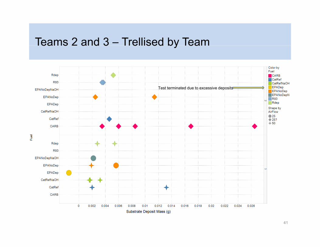
Teams 2 and 3 ndash Trellised by Teamea s a d 3 e sed by ea
Test terminated due to excessive deposits
41
All Data ndash Trellised by Teamata e sed by ea
Test terminated due to excessive deposits
42
Teams 2 and 3 ndash Trellised by Teamea s a d 3 e sed by ea
Test terminated due to excessive deposits
43
I RiInnospec Rig
Methodologyet odo ogy
Injector rig conditions used for the program
Variable Setting
Injectors 4 new Bosch CRIN1 injectors per runper run
Filters 2 new Fleetguard FF167 filters per run
Pre-rig clean Repeat rinses with MeOH MEPP (Methoxy Propoxy Propanol) and test diesel
Run time 100 hours
Cycle Standard rig test cycle
Injector tip temperature 180ordmC
Fuel tank temperature 35ordmC
Fuel volume 32 litres
RPM flywheel 1200
45
Analysisa ys s
The following tests were carried out to measure deposition rates
Component Test Measurement Testing Details
Filter Insoluble Carbon Total carbon from both filters by TPO (microgcm-2)
Performed in triplicate on both filters from runy ( g )
See next page for definition of TPO
Injector Back Leakage Change in performance from new injector
Performed in duplicate on each injector
Injector Pressure Drop Change in performance from new injector
5 tests on each injector
I j t I j t Ti D it N li d bl k t d T t f d ll 4Injector Injector Tip Deposit Normalized blank corrected carbon deposit level by TPO
Test performed on all 4 injectors from run
Injector Injector Needle Deposit
Injector Injector Push Rod Deposit
46
Temperature Programmed Oxidation (TPO)e pe atu e og a ed O dat o ( O)
Sample is placed in a quartz sample boat and inserted into a temperature-controlled furnace where it is heated in a calibrated oxygen atmosphere Oxygen feed rate = 0 75 liters perOxygen feed rate 075 liters per minuteStarting temperature = 270degC For testing the temperature was increased to 700degC at a rate of 100degC per minute The CO2 resulting from the oxidation of the carbon is detected by calibrated IR detectorsdetectors Total carbon result calculated from amount of CO2 ndash can either be expressed per unit area (if known) or e p essed pe u t a ea ( o ) onormalized to a surface area = 1
47
I RiInnospec Rig
Data Presentation and Comments
Analysis ndash Insoluble Filter Depositsa ys s so ub e te epos ts
Both fuel tank filters removed and dismantled5 x 1 cm vertical sections removed for analysis from each filterEach section placed in 60 mLEach section placed in 60 mL tri-solvent (602020 toluene acetonemethanol) and placed in an ultrasonic bath for 30 minutesSolvent then filtered through 07-micron GF filter paperFilter paper rinsed with 2 x 25 mL washes of isooctane and dried atwashes of isooctane and dried at 100degC for 2 hoursTest performed in triplicate on both filters
49
CRC Testing ndash Filter DepositsC C est g te epos ts
Each GF filter paper run on RC612 TPO analyzer
Run Fuel Average Total Carbon Deposit (microgcm2)analyzer
Sample was run under ramp method from 270degC to 700degCTotal carbon calculated per unit area of original fuel tank filter paper (10 cm2)
Deposit (microgcm )
1 RNoDep 10837
2 RDep 8837
3 EPANoDep 16650original fuel tank filter paper (10 cm )Results quoted as average total carbon for both filters
p
4 EPADep 10360
5 R93 8013
6 HiSulf 6650
ObservationsHi Sulf R93 and CARB gave lowest resultsIncreased filter deposits observed in Runs 3 and 14 following NaOH-treated runs
f 2 d 13 ti l i
7 CARB 7343
8 CARB 7380
9 HiSulf 8127
of 2 and 13 ndash suggesting cleaning process not removing all NaOH as second run with same fuel gave appreciably different resultsVery good repeatability achieved with the exception of runs that followed NaOH
10 R93 6550
11 EPADep 8350
12 EPANoDep 9323
13 RDep 67 53exception of runs that followed NaOH addition (3 and 14)
13 RDep 6753
14 RNoDep 7377
50
Injector Testingjecto est g
Each injector removed from rig and mounted in DIT31 Injector TesterEach injector measured pre- and post-test for
Back leakagendash Back leakagendash Pressure drop
Result quoted is differencebetween pre- and post-testbetween pre and post test
51
CRC Testing ndash Back LeakageC C est g ac ea age
Test performed in duplicate on each of all 4 injectors Run Fuel Average Change
(Pre- to Post-Test)Secondsall 4 injectorsResults quoted are the average change for all injectors from each runInjector is pressurised to 1100 barAir supply is switched off and the pressure
(Pre- to Post-Test)Seconds
1 RNoDep -563
2 RDep -508
3 EPANoDep 185allowed to return to ambientBack leakage is quoted as the time taken to fall from 600 to 200 barThe faster the time the greater the likelihood of injector seal failure
p
4 EPADep -250
5 R93 401
6 HiSulf -318likelihood of injector seal failure The higher the negative value the greater the loss of performance
Observations
7 CARB -659
8 CARB -099
9 HiSulf -408
High degree of variability between batches of same fuelDifficult to quantify significant changes in performanceNot recommended as a performance
10 R93 -323
11 EPADep -154
12 EPANoDep -248
13 RDep -4 55Not recommended as a performance measurement
13 RDep -455
14 RNoDep -098
52
CRC Testing ndash Pressure DropC C est g essu e op
Test performed 5 times on each of all 4 injectors Run Fuel Average Change
(Pre- to Post-Test)BarinjectorsResults quoted are the average change for all injectors from each runInjector is pressurised to 1100 barAir supply is switched off and the pressure
(Pre- to Post-Test)Bar
1 RNoDep 015
2 RDep 280
3 EPANoDep 455pp y pallowed to return to ambientAt 750 bar the injector is fired for 8 msThe pressure drop during firing is measured in barA i ifi t f ll i d f t t t
p
4 EPADep 245
5 R93 400
6 HiSulf 470A significant fall in pressure drop from start to finish is indicative of deposit buildupAn significant increase in pressure drop could be indicative of injectorlsquostickingrsquo
C l i (t d t )
7 CARB 145
8 CARB -213
9 HiSulf 387
Conclusions (to date)High degree of variability between batches of same fuelDifficult to quantify significant changes in performance
10 R93 1030
11 EPADep -205
12 EPANoDep 245
13 RDep 0 95performanceNot recommended as a performance measurement
13 RDep 095
14 RNoDep 735
53
Injector Dismantlingjecto s a t g
All 4 injectors from each run dismantled3 t t i d f l i3 parts retained for analysis
ndash Tipndash Needlendash Pushrod
Parts rinsed in toluene then acetone then dried in oven for 2 hoursTPO analysis performed on all 4 injectors from each run ndashfinal result is average of 4 testsFi l d it l l l l t d b i b l lFinal deposit level calculated by measuring carbon levels and subtracting blank injector resultTip and needle analysis too variable ndash did not differentiate between fuels
54
CRC Testing ndash Injector TipC C est g jecto p
Run Fuel Average Total Carbon Deposit (microgcm2)
Each tip sectioned using diamond saw to allow testing of tip section exposed in rig Deposit (microgcm2)
1 RNoDep -598
2 RDep 467
3 EPANoDep -533
allow testing of tip section exposed in rigSample run on RC612 TPO analyzer from 270degC to 700degCEach test was baseline corrected against a new pushrod p
4 EPADep -698
5 R93 15785
6 HiSulf 333
new pushrodResults are based on a fixed surface area of 1 cm2
Conclusions (to date)7 CARB 1763
8 CARB -073
9 HiSulf -367
Conclusions (to date)Excess variability in results ndash most likely to be due to washing effect in post-injector drain (C of V typically gt100)Difficult to draw any conclusions ndash analysis
10 R93 6068
11 EPADep 3973
12 EPANoDep -280
13 RDep 30 10
y ynot satisfactory in current form Variation in test resulted in some totals being less than blank needleNot recommended as a performance
d i d b 13 RDep 3010
14 RNoDep 3045
55
measurement ndash drain needs to be redesigned
CRC Testing ndash Injector NeedleC C est g jecto eed e
Each needle sectioned using diamond saw to allow testing of needle section with no Run Fuel Average Total Carbon
Deposit (microgcm2)to allow testing of needle section with no DLC coatingSample run on RC612 TPO analyser from 270degC to 700degCEach test was baseline corrected against a
Deposit (microgcm2)
1 RNoDep -010
2 RDep 163
3 EPANoDep 283Each test was baseline corrected against a new pushrodResults are based on a fixed surface area of 1 cm2
p
4 EPADep 030
5 R93 133
6 HiSulf -143
Conclusions (to date)Excess variability in results ndash most likely to be due to minute levels of deposit on section (C of V typically gt100)
7 CARB 885
8 CARB 367
9 HiSulf 510
Difficult to draw any conclusions ndash analysis not satisfactory in current form Variation in test resulted in some totals being less than blank needleNot recommended as performance
10 R93 1453
11 EPADep 1333
12 EPANoDep 133
13 RDep 13 15Not recommended as performance measurement
13 RDep 1315
14 RNoDep 1478
56
CRC Testing ndash Injector Push RodC C est g jecto us od
Each pushrod run on RC612 TPO analyzer from 270degC to 700degC Run Fuel Average Total Carbon
Deposit (microgcm2)from 270 C to 700 CEach test was baseline corrected against a new pushrodResults are based on a fixed surface area of 1 cm2
Deposit (microgcm2)
1 RNoDep 1620
2 RDep 1538
3 EPANoDep 1735p
4 EPADep 1103
5 R93 1187
6 HiSulf 900
ConclusionsAll fuels created deposits on the pushrodVery good repeatability achieved with the
7 CARB 1863
8 CARB 1590
9 HiSulf 1098Very good repeatability achieved with the exception of Runs 3 and 14 that followed NaOH addition Runs 2 and 13EPADep and HiSulf gave lowest resultsRNoDep gave highest results but this may be skewed by previous run
10 R93 1493
11 EPADep 1215
12 EPANoDep 1220
13 RDep 14 10be skewed by previous runTest appears to differentiate between fuels
13 RDep 1410
14 RNoDep 3548
57
Innospec Rig Summary ndash Prorsquosospec g Su a y o s
Two tests identified as showing differentiation between fuels with good repeatability
ndash Total insoluble carbon from post-tank filtersndash Carbon deposit level on injector pushrod
Rig config ration no reliable no breakdo ns d ring testingRig configuration now reliable ndash no breakdowns during testingRig uses real engine parts filters common rail pump and injectorsRig set up as close as possible to engine test without combustionRi h th t ti l t t f di l i j t ld h t bRig has the potential to use any type of diesel injector ndash would have to be discussed with manufacturer
58
Innospec Rig Summary ndash Conrsquosospec g Su a y Co s
Equipment costly to install Initially rig ~$100K TPO analyzer $70KRig adapted in-house since purchase to include injector heaters and extraction cabinetEquipment manufacturer relatively small company ndash limited supportTest is costly ndash $2K for injectors and filters per test 3 man-days (cost = )Test is costly $2K for injectors and filters per test 3 man days (cost ) required per test including analysis (not including periodic monitoring during test) Test takes 100 hours analysis ~8 hoursO i ht i i d t t it d d i i ht iOvernight running required ndash test monitored during night runningCleaning step is potentially hazardous time consuming and unsuitable for a bench rig ndash up to 75 liters of solvent and fuel required (in total for cleaning)g)Running NaOH in rig may have adversely affected subsequent runsRig conditions may not be severe enough to establish clear differences between fuelsFurther work may be required to improve injector drainage systemFurther work may be required to improve injector drainage systemFor true correlation test would have to be run against actual engine data
59
I RiInnospec Rig
More Formal Data Analysis
Filters Average Total Insoluble Carbon Deposit (microgcmsup2)
61
Filters Average Total Insoluble Carbon Deposit (microgcmsup2)
Pairs of fuel with overlapping intervals were not significantly (α=005) different from each other
62
Filters Average Total Insoluble Carbon Deposit (microgcmsup2)
resi
dual
sud
entiz
ed
Stu
63
Injector Pushrod TPO Carbon Deposit (microgcmsup2)
64
IPRAvg = average of four injectors IPROSA = outlier screened average
Injector Pushrod TPO Carbon Deposit (microgcmsup2)
Outlier Screened AverageOutlier Screened Average
Pairs of fuel with overlapping intervals were not significantly (α=005) different from each other
65
Outlier Screened Average
Injector Pushrod TPO Carbon Deposit (microgcmsup2)
Outlier Screened Averagere
sidu
als
uden
tized
S
tu
66
ConclusionsCo c us o s
Results from this scoping study did not confirm that p g yeither one of these rigs in their present state could discriminate among deposit forming and not deposit forming fuelsforming fuelsIf in-house work by either sponsor results in changes to provide differentiation CRC will consider further evaluationA new rig offered by Delphi is being considered
67
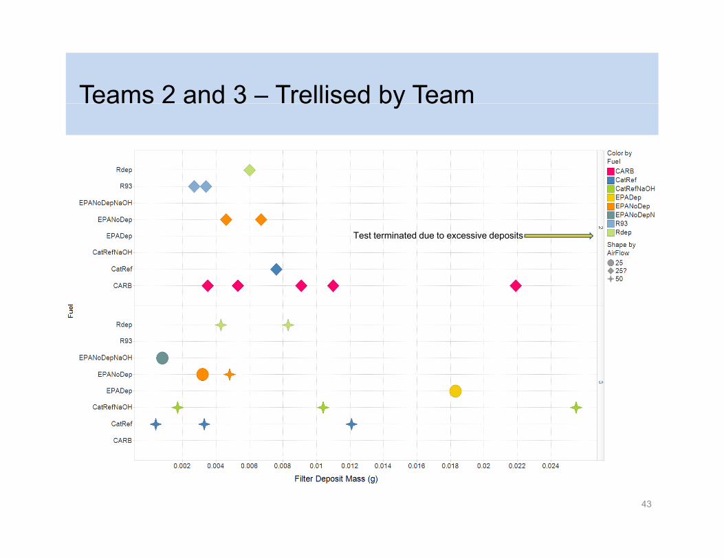

I RiInnospec Rig
Methodologyet odo ogy
Injector rig conditions used for the program
Variable Setting
Injectors 4 new Bosch CRIN1 injectors per runper run
Filters 2 new Fleetguard FF167 filters per run
Pre-rig clean Repeat rinses with MeOH MEPP (Methoxy Propoxy Propanol) and test diesel
Run time 100 hours
Cycle Standard rig test cycle
Injector tip temperature 180ordmC
Fuel tank temperature 35ordmC
Fuel volume 32 litres
RPM flywheel 1200
45
Analysisa ys s
The following tests were carried out to measure deposition rates
Component Test Measurement Testing Details
Filter Insoluble Carbon Total carbon from both filters by TPO (microgcm-2)
Performed in triplicate on both filters from runy ( g )
See next page for definition of TPO
Injector Back Leakage Change in performance from new injector
Performed in duplicate on each injector
Injector Pressure Drop Change in performance from new injector
5 tests on each injector
I j t I j t Ti D it N li d bl k t d T t f d ll 4Injector Injector Tip Deposit Normalized blank corrected carbon deposit level by TPO
Test performed on all 4 injectors from run
Injector Injector Needle Deposit
Injector Injector Push Rod Deposit
46
Temperature Programmed Oxidation (TPO)e pe atu e og a ed O dat o ( O)
Sample is placed in a quartz sample boat and inserted into a temperature-controlled furnace where it is heated in a calibrated oxygen atmosphere Oxygen feed rate = 0 75 liters perOxygen feed rate 075 liters per minuteStarting temperature = 270degC For testing the temperature was increased to 700degC at a rate of 100degC per minute The CO2 resulting from the oxidation of the carbon is detected by calibrated IR detectorsdetectors Total carbon result calculated from amount of CO2 ndash can either be expressed per unit area (if known) or e p essed pe u t a ea ( o ) onormalized to a surface area = 1
47
I RiInnospec Rig
Data Presentation and Comments
Analysis ndash Insoluble Filter Depositsa ys s so ub e te epos ts
Both fuel tank filters removed and dismantled5 x 1 cm vertical sections removed for analysis from each filterEach section placed in 60 mLEach section placed in 60 mL tri-solvent (602020 toluene acetonemethanol) and placed in an ultrasonic bath for 30 minutesSolvent then filtered through 07-micron GF filter paperFilter paper rinsed with 2 x 25 mL washes of isooctane and dried atwashes of isooctane and dried at 100degC for 2 hoursTest performed in triplicate on both filters
49
CRC Testing ndash Filter DepositsC C est g te epos ts
Each GF filter paper run on RC612 TPO analyzer
Run Fuel Average Total Carbon Deposit (microgcm2)analyzer
Sample was run under ramp method from 270degC to 700degCTotal carbon calculated per unit area of original fuel tank filter paper (10 cm2)
Deposit (microgcm )
1 RNoDep 10837
2 RDep 8837
3 EPANoDep 16650original fuel tank filter paper (10 cm )Results quoted as average total carbon for both filters
p
4 EPADep 10360
5 R93 8013
6 HiSulf 6650
ObservationsHi Sulf R93 and CARB gave lowest resultsIncreased filter deposits observed in Runs 3 and 14 following NaOH-treated runs
f 2 d 13 ti l i
7 CARB 7343
8 CARB 7380
9 HiSulf 8127
of 2 and 13 ndash suggesting cleaning process not removing all NaOH as second run with same fuel gave appreciably different resultsVery good repeatability achieved with the exception of runs that followed NaOH
10 R93 6550
11 EPADep 8350
12 EPANoDep 9323
13 RDep 67 53exception of runs that followed NaOH addition (3 and 14)
13 RDep 6753
14 RNoDep 7377
50
Injector Testingjecto est g
Each injector removed from rig and mounted in DIT31 Injector TesterEach injector measured pre- and post-test for
Back leakagendash Back leakagendash Pressure drop
Result quoted is differencebetween pre- and post-testbetween pre and post test
51
CRC Testing ndash Back LeakageC C est g ac ea age
Test performed in duplicate on each of all 4 injectors Run Fuel Average Change
(Pre- to Post-Test)Secondsall 4 injectorsResults quoted are the average change for all injectors from each runInjector is pressurised to 1100 barAir supply is switched off and the pressure
(Pre- to Post-Test)Seconds
1 RNoDep -563
2 RDep -508
3 EPANoDep 185allowed to return to ambientBack leakage is quoted as the time taken to fall from 600 to 200 barThe faster the time the greater the likelihood of injector seal failure
p
4 EPADep -250
5 R93 401
6 HiSulf -318likelihood of injector seal failure The higher the negative value the greater the loss of performance
Observations
7 CARB -659
8 CARB -099
9 HiSulf -408
High degree of variability between batches of same fuelDifficult to quantify significant changes in performanceNot recommended as a performance
10 R93 -323
11 EPADep -154
12 EPANoDep -248
13 RDep -4 55Not recommended as a performance measurement
13 RDep -455
14 RNoDep -098
52
CRC Testing ndash Pressure DropC C est g essu e op
Test performed 5 times on each of all 4 injectors Run Fuel Average Change
(Pre- to Post-Test)BarinjectorsResults quoted are the average change for all injectors from each runInjector is pressurised to 1100 barAir supply is switched off and the pressure
(Pre- to Post-Test)Bar
1 RNoDep 015
2 RDep 280
3 EPANoDep 455pp y pallowed to return to ambientAt 750 bar the injector is fired for 8 msThe pressure drop during firing is measured in barA i ifi t f ll i d f t t t
p
4 EPADep 245
5 R93 400
6 HiSulf 470A significant fall in pressure drop from start to finish is indicative of deposit buildupAn significant increase in pressure drop could be indicative of injectorlsquostickingrsquo
C l i (t d t )
7 CARB 145
8 CARB -213
9 HiSulf 387
Conclusions (to date)High degree of variability between batches of same fuelDifficult to quantify significant changes in performance
10 R93 1030
11 EPADep -205
12 EPANoDep 245
13 RDep 0 95performanceNot recommended as a performance measurement
13 RDep 095
14 RNoDep 735
53
Injector Dismantlingjecto s a t g
All 4 injectors from each run dismantled3 t t i d f l i3 parts retained for analysis
ndash Tipndash Needlendash Pushrod
Parts rinsed in toluene then acetone then dried in oven for 2 hoursTPO analysis performed on all 4 injectors from each run ndashfinal result is average of 4 testsFi l d it l l l l t d b i b l lFinal deposit level calculated by measuring carbon levels and subtracting blank injector resultTip and needle analysis too variable ndash did not differentiate between fuels
54
CRC Testing ndash Injector TipC C est g jecto p
Run Fuel Average Total Carbon Deposit (microgcm2)
Each tip sectioned using diamond saw to allow testing of tip section exposed in rig Deposit (microgcm2)
1 RNoDep -598
2 RDep 467
3 EPANoDep -533
allow testing of tip section exposed in rigSample run on RC612 TPO analyzer from 270degC to 700degCEach test was baseline corrected against a new pushrod p
4 EPADep -698
5 R93 15785
6 HiSulf 333
new pushrodResults are based on a fixed surface area of 1 cm2
Conclusions (to date)7 CARB 1763
8 CARB -073
9 HiSulf -367
Conclusions (to date)Excess variability in results ndash most likely to be due to washing effect in post-injector drain (C of V typically gt100)Difficult to draw any conclusions ndash analysis
10 R93 6068
11 EPADep 3973
12 EPANoDep -280
13 RDep 30 10
y ynot satisfactory in current form Variation in test resulted in some totals being less than blank needleNot recommended as a performance
d i d b 13 RDep 3010
14 RNoDep 3045
55
measurement ndash drain needs to be redesigned
CRC Testing ndash Injector NeedleC C est g jecto eed e
Each needle sectioned using diamond saw to allow testing of needle section with no Run Fuel Average Total Carbon
Deposit (microgcm2)to allow testing of needle section with no DLC coatingSample run on RC612 TPO analyser from 270degC to 700degCEach test was baseline corrected against a
Deposit (microgcm2)
1 RNoDep -010
2 RDep 163
3 EPANoDep 283Each test was baseline corrected against a new pushrodResults are based on a fixed surface area of 1 cm2
p
4 EPADep 030
5 R93 133
6 HiSulf -143
Conclusions (to date)Excess variability in results ndash most likely to be due to minute levels of deposit on section (C of V typically gt100)
7 CARB 885
8 CARB 367
9 HiSulf 510
Difficult to draw any conclusions ndash analysis not satisfactory in current form Variation in test resulted in some totals being less than blank needleNot recommended as performance
10 R93 1453
11 EPADep 1333
12 EPANoDep 133
13 RDep 13 15Not recommended as performance measurement
13 RDep 1315
14 RNoDep 1478
56
CRC Testing ndash Injector Push RodC C est g jecto us od
Each pushrod run on RC612 TPO analyzer from 270degC to 700degC Run Fuel Average Total Carbon
Deposit (microgcm2)from 270 C to 700 CEach test was baseline corrected against a new pushrodResults are based on a fixed surface area of 1 cm2
Deposit (microgcm2)
1 RNoDep 1620
2 RDep 1538
3 EPANoDep 1735p
4 EPADep 1103
5 R93 1187
6 HiSulf 900
ConclusionsAll fuels created deposits on the pushrodVery good repeatability achieved with the
7 CARB 1863
8 CARB 1590
9 HiSulf 1098Very good repeatability achieved with the exception of Runs 3 and 14 that followed NaOH addition Runs 2 and 13EPADep and HiSulf gave lowest resultsRNoDep gave highest results but this may be skewed by previous run
10 R93 1493
11 EPADep 1215
12 EPANoDep 1220
13 RDep 14 10be skewed by previous runTest appears to differentiate between fuels
13 RDep 1410
14 RNoDep 3548
57
Innospec Rig Summary ndash Prorsquosospec g Su a y o s
Two tests identified as showing differentiation between fuels with good repeatability
ndash Total insoluble carbon from post-tank filtersndash Carbon deposit level on injector pushrod
Rig config ration no reliable no breakdo ns d ring testingRig configuration now reliable ndash no breakdowns during testingRig uses real engine parts filters common rail pump and injectorsRig set up as close as possible to engine test without combustionRi h th t ti l t t f di l i j t ld h t bRig has the potential to use any type of diesel injector ndash would have to be discussed with manufacturer
58
Innospec Rig Summary ndash Conrsquosospec g Su a y Co s
Equipment costly to install Initially rig ~$100K TPO analyzer $70KRig adapted in-house since purchase to include injector heaters and extraction cabinetEquipment manufacturer relatively small company ndash limited supportTest is costly ndash $2K for injectors and filters per test 3 man-days (cost = )Test is costly $2K for injectors and filters per test 3 man days (cost ) required per test including analysis (not including periodic monitoring during test) Test takes 100 hours analysis ~8 hoursO i ht i i d t t it d d i i ht iOvernight running required ndash test monitored during night runningCleaning step is potentially hazardous time consuming and unsuitable for a bench rig ndash up to 75 liters of solvent and fuel required (in total for cleaning)g)Running NaOH in rig may have adversely affected subsequent runsRig conditions may not be severe enough to establish clear differences between fuelsFurther work may be required to improve injector drainage systemFurther work may be required to improve injector drainage systemFor true correlation test would have to be run against actual engine data
59
I RiInnospec Rig
More Formal Data Analysis
Filters Average Total Insoluble Carbon Deposit (microgcmsup2)
61
Filters Average Total Insoluble Carbon Deposit (microgcmsup2)
Pairs of fuel with overlapping intervals were not significantly (α=005) different from each other
62
Filters Average Total Insoluble Carbon Deposit (microgcmsup2)
resi
dual
sud
entiz
ed
Stu
63
Injector Pushrod TPO Carbon Deposit (microgcmsup2)
64
IPRAvg = average of four injectors IPROSA = outlier screened average
Injector Pushrod TPO Carbon Deposit (microgcmsup2)
Outlier Screened AverageOutlier Screened Average
Pairs of fuel with overlapping intervals were not significantly (α=005) different from each other
65
Outlier Screened Average
Injector Pushrod TPO Carbon Deposit (microgcmsup2)
Outlier Screened Averagere
sidu
als
uden
tized
S
tu
66
ConclusionsCo c us o s
Results from this scoping study did not confirm that p g yeither one of these rigs in their present state could discriminate among deposit forming and not deposit forming fuelsforming fuelsIf in-house work by either sponsor results in changes to provide differentiation CRC will consider further evaluationA new rig offered by Delphi is being considered
67

I RiInnospec Rig
Data Presentation and Comments
Analysis ndash Insoluble Filter Depositsa ys s so ub e te epos ts
Both fuel tank filters removed and dismantled5 x 1 cm vertical sections removed for analysis from each filterEach section placed in 60 mLEach section placed in 60 mL tri-solvent (602020 toluene acetonemethanol) and placed in an ultrasonic bath for 30 minutesSolvent then filtered through 07-micron GF filter paperFilter paper rinsed with 2 x 25 mL washes of isooctane and dried atwashes of isooctane and dried at 100degC for 2 hoursTest performed in triplicate on both filters
49
CRC Testing ndash Filter DepositsC C est g te epos ts
Each GF filter paper run on RC612 TPO analyzer
Run Fuel Average Total Carbon Deposit (microgcm2)analyzer
Sample was run under ramp method from 270degC to 700degCTotal carbon calculated per unit area of original fuel tank filter paper (10 cm2)
Deposit (microgcm )
1 RNoDep 10837
2 RDep 8837
3 EPANoDep 16650original fuel tank filter paper (10 cm )Results quoted as average total carbon for both filters
p
4 EPADep 10360
5 R93 8013
6 HiSulf 6650
ObservationsHi Sulf R93 and CARB gave lowest resultsIncreased filter deposits observed in Runs 3 and 14 following NaOH-treated runs
f 2 d 13 ti l i
7 CARB 7343
8 CARB 7380
9 HiSulf 8127
of 2 and 13 ndash suggesting cleaning process not removing all NaOH as second run with same fuel gave appreciably different resultsVery good repeatability achieved with the exception of runs that followed NaOH
10 R93 6550
11 EPADep 8350
12 EPANoDep 9323
13 RDep 67 53exception of runs that followed NaOH addition (3 and 14)
13 RDep 6753
14 RNoDep 7377
50
Injector Testingjecto est g
Each injector removed from rig and mounted in DIT31 Injector TesterEach injector measured pre- and post-test for
Back leakagendash Back leakagendash Pressure drop
Result quoted is differencebetween pre- and post-testbetween pre and post test
51
CRC Testing ndash Back LeakageC C est g ac ea age
Test performed in duplicate on each of all 4 injectors Run Fuel Average Change
(Pre- to Post-Test)Secondsall 4 injectorsResults quoted are the average change for all injectors from each runInjector is pressurised to 1100 barAir supply is switched off and the pressure
(Pre- to Post-Test)Seconds
1 RNoDep -563
2 RDep -508
3 EPANoDep 185allowed to return to ambientBack leakage is quoted as the time taken to fall from 600 to 200 barThe faster the time the greater the likelihood of injector seal failure
p
4 EPADep -250
5 R93 401
6 HiSulf -318likelihood of injector seal failure The higher the negative value the greater the loss of performance
Observations
7 CARB -659
8 CARB -099
9 HiSulf -408
High degree of variability between batches of same fuelDifficult to quantify significant changes in performanceNot recommended as a performance
10 R93 -323
11 EPADep -154
12 EPANoDep -248
13 RDep -4 55Not recommended as a performance measurement
13 RDep -455
14 RNoDep -098
52
CRC Testing ndash Pressure DropC C est g essu e op
Test performed 5 times on each of all 4 injectors Run Fuel Average Change
(Pre- to Post-Test)BarinjectorsResults quoted are the average change for all injectors from each runInjector is pressurised to 1100 barAir supply is switched off and the pressure
(Pre- to Post-Test)Bar
1 RNoDep 015
2 RDep 280
3 EPANoDep 455pp y pallowed to return to ambientAt 750 bar the injector is fired for 8 msThe pressure drop during firing is measured in barA i ifi t f ll i d f t t t
p
4 EPADep 245
5 R93 400
6 HiSulf 470A significant fall in pressure drop from start to finish is indicative of deposit buildupAn significant increase in pressure drop could be indicative of injectorlsquostickingrsquo
C l i (t d t )
7 CARB 145
8 CARB -213
9 HiSulf 387
Conclusions (to date)High degree of variability between batches of same fuelDifficult to quantify significant changes in performance
10 R93 1030
11 EPADep -205
12 EPANoDep 245
13 RDep 0 95performanceNot recommended as a performance measurement
13 RDep 095
14 RNoDep 735
53
Injector Dismantlingjecto s a t g
All 4 injectors from each run dismantled3 t t i d f l i3 parts retained for analysis
ndash Tipndash Needlendash Pushrod
Parts rinsed in toluene then acetone then dried in oven for 2 hoursTPO analysis performed on all 4 injectors from each run ndashfinal result is average of 4 testsFi l d it l l l l t d b i b l lFinal deposit level calculated by measuring carbon levels and subtracting blank injector resultTip and needle analysis too variable ndash did not differentiate between fuels
54
CRC Testing ndash Injector TipC C est g jecto p
Run Fuel Average Total Carbon Deposit (microgcm2)
Each tip sectioned using diamond saw to allow testing of tip section exposed in rig Deposit (microgcm2)
1 RNoDep -598
2 RDep 467
3 EPANoDep -533
allow testing of tip section exposed in rigSample run on RC612 TPO analyzer from 270degC to 700degCEach test was baseline corrected against a new pushrod p
4 EPADep -698
5 R93 15785
6 HiSulf 333
new pushrodResults are based on a fixed surface area of 1 cm2
Conclusions (to date)7 CARB 1763
8 CARB -073
9 HiSulf -367
Conclusions (to date)Excess variability in results ndash most likely to be due to washing effect in post-injector drain (C of V typically gt100)Difficult to draw any conclusions ndash analysis
10 R93 6068
11 EPADep 3973
12 EPANoDep -280
13 RDep 30 10
y ynot satisfactory in current form Variation in test resulted in some totals being less than blank needleNot recommended as a performance
d i d b 13 RDep 3010
14 RNoDep 3045
55
measurement ndash drain needs to be redesigned
CRC Testing ndash Injector NeedleC C est g jecto eed e
Each needle sectioned using diamond saw to allow testing of needle section with no Run Fuel Average Total Carbon
Deposit (microgcm2)to allow testing of needle section with no DLC coatingSample run on RC612 TPO analyser from 270degC to 700degCEach test was baseline corrected against a
Deposit (microgcm2)
1 RNoDep -010
2 RDep 163
3 EPANoDep 283Each test was baseline corrected against a new pushrodResults are based on a fixed surface area of 1 cm2
p
4 EPADep 030
5 R93 133
6 HiSulf -143
Conclusions (to date)Excess variability in results ndash most likely to be due to minute levels of deposit on section (C of V typically gt100)
7 CARB 885
8 CARB 367
9 HiSulf 510
Difficult to draw any conclusions ndash analysis not satisfactory in current form Variation in test resulted in some totals being less than blank needleNot recommended as performance
10 R93 1453
11 EPADep 1333
12 EPANoDep 133
13 RDep 13 15Not recommended as performance measurement
13 RDep 1315
14 RNoDep 1478
56
CRC Testing ndash Injector Push RodC C est g jecto us od
Each pushrod run on RC612 TPO analyzer from 270degC to 700degC Run Fuel Average Total Carbon
Deposit (microgcm2)from 270 C to 700 CEach test was baseline corrected against a new pushrodResults are based on a fixed surface area of 1 cm2
Deposit (microgcm2)
1 RNoDep 1620
2 RDep 1538
3 EPANoDep 1735p
4 EPADep 1103
5 R93 1187
6 HiSulf 900
ConclusionsAll fuels created deposits on the pushrodVery good repeatability achieved with the
7 CARB 1863
8 CARB 1590
9 HiSulf 1098Very good repeatability achieved with the exception of Runs 3 and 14 that followed NaOH addition Runs 2 and 13EPADep and HiSulf gave lowest resultsRNoDep gave highest results but this may be skewed by previous run
10 R93 1493
11 EPADep 1215
12 EPANoDep 1220
13 RDep 14 10be skewed by previous runTest appears to differentiate between fuels
13 RDep 1410
14 RNoDep 3548
57
Innospec Rig Summary ndash Prorsquosospec g Su a y o s
Two tests identified as showing differentiation between fuels with good repeatability
ndash Total insoluble carbon from post-tank filtersndash Carbon deposit level on injector pushrod
Rig config ration no reliable no breakdo ns d ring testingRig configuration now reliable ndash no breakdowns during testingRig uses real engine parts filters common rail pump and injectorsRig set up as close as possible to engine test without combustionRi h th t ti l t t f di l i j t ld h t bRig has the potential to use any type of diesel injector ndash would have to be discussed with manufacturer
58
Innospec Rig Summary ndash Conrsquosospec g Su a y Co s
Equipment costly to install Initially rig ~$100K TPO analyzer $70KRig adapted in-house since purchase to include injector heaters and extraction cabinetEquipment manufacturer relatively small company ndash limited supportTest is costly ndash $2K for injectors and filters per test 3 man-days (cost = )Test is costly $2K for injectors and filters per test 3 man days (cost ) required per test including analysis (not including periodic monitoring during test) Test takes 100 hours analysis ~8 hoursO i ht i i d t t it d d i i ht iOvernight running required ndash test monitored during night runningCleaning step is potentially hazardous time consuming and unsuitable for a bench rig ndash up to 75 liters of solvent and fuel required (in total for cleaning)g)Running NaOH in rig may have adversely affected subsequent runsRig conditions may not be severe enough to establish clear differences between fuelsFurther work may be required to improve injector drainage systemFurther work may be required to improve injector drainage systemFor true correlation test would have to be run against actual engine data
59
I RiInnospec Rig
More Formal Data Analysis
Filters Average Total Insoluble Carbon Deposit (microgcmsup2)
61
Filters Average Total Insoluble Carbon Deposit (microgcmsup2)
Pairs of fuel with overlapping intervals were not significantly (α=005) different from each other
62
Filters Average Total Insoluble Carbon Deposit (microgcmsup2)
resi
dual
sud
entiz
ed
Stu
63
Injector Pushrod TPO Carbon Deposit (microgcmsup2)
64
IPRAvg = average of four injectors IPROSA = outlier screened average
Injector Pushrod TPO Carbon Deposit (microgcmsup2)
Outlier Screened AverageOutlier Screened Average
Pairs of fuel with overlapping intervals were not significantly (α=005) different from each other
65
Outlier Screened Average
Injector Pushrod TPO Carbon Deposit (microgcmsup2)
Outlier Screened Averagere
sidu
als
uden
tized
S
tu
66
ConclusionsCo c us o s
Results from this scoping study did not confirm that p g yeither one of these rigs in their present state could discriminate among deposit forming and not deposit forming fuelsforming fuelsIf in-house work by either sponsor results in changes to provide differentiation CRC will consider further evaluationA new rig offered by Delphi is being considered
67
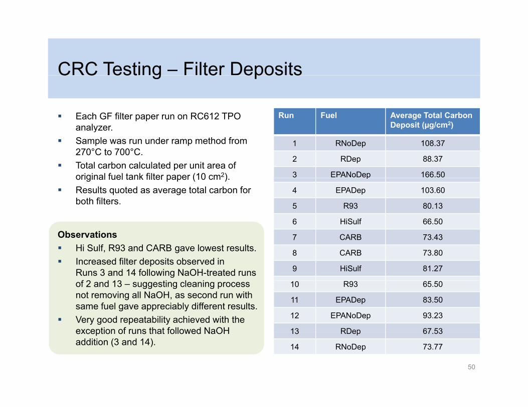
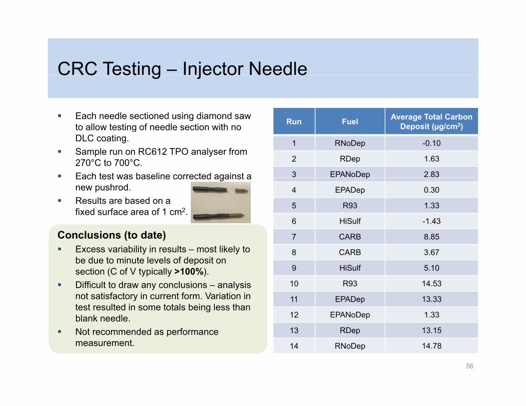

Filters Average Total Insoluble Carbon Deposit (microgcmsup2)
Pairs of fuel with overlapping intervals were not significantly (α=005) different from each other
62
Filters Average Total Insoluble Carbon Deposit (microgcmsup2)
resi
dual
sud
entiz
ed
Stu
63
Injector Pushrod TPO Carbon Deposit (microgcmsup2)
64
IPRAvg = average of four injectors IPROSA = outlier screened average
Injector Pushrod TPO Carbon Deposit (microgcmsup2)
Outlier Screened AverageOutlier Screened Average
Pairs of fuel with overlapping intervals were not significantly (α=005) different from each other
65
Outlier Screened Average
Injector Pushrod TPO Carbon Deposit (microgcmsup2)
Outlier Screened Averagere
sidu
als
uden
tized
S
tu
66
ConclusionsCo c us o s
Results from this scoping study did not confirm that p g yeither one of these rigs in their present state could discriminate among deposit forming and not deposit forming fuelsforming fuelsIf in-house work by either sponsor results in changes to provide differentiation CRC will consider further evaluationA new rig offered by Delphi is being considered
67
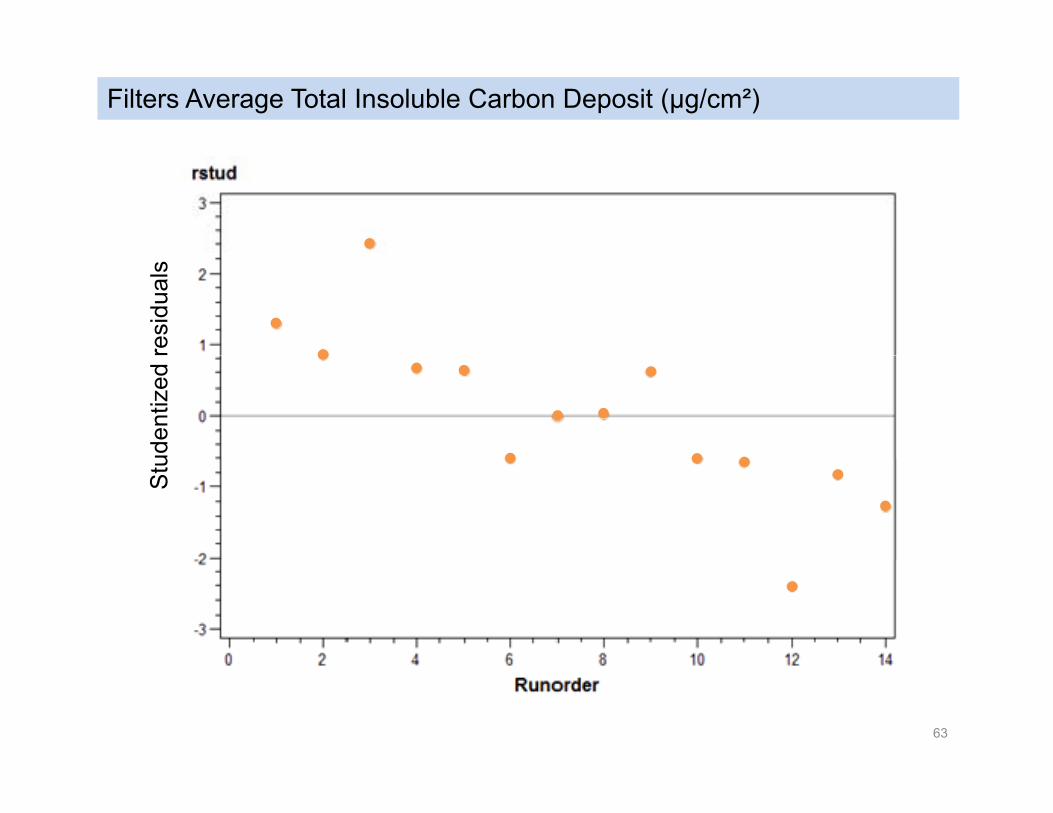
Filters Average Total Insoluble Carbon Deposit (microgcmsup2)
resi
dual
sud
entiz
ed
Stu
63
Injector Pushrod TPO Carbon Deposit (microgcmsup2)
64
IPRAvg = average of four injectors IPROSA = outlier screened average
Injector Pushrod TPO Carbon Deposit (microgcmsup2)
Outlier Screened AverageOutlier Screened Average
Pairs of fuel with overlapping intervals were not significantly (α=005) different from each other
65
Outlier Screened Average
Injector Pushrod TPO Carbon Deposit (microgcmsup2)
Outlier Screened Averagere
sidu
als
uden
tized
S
tu
66
ConclusionsCo c us o s
Results from this scoping study did not confirm that p g yeither one of these rigs in their present state could discriminate among deposit forming and not deposit forming fuelsforming fuelsIf in-house work by either sponsor results in changes to provide differentiation CRC will consider further evaluationA new rig offered by Delphi is being considered
67
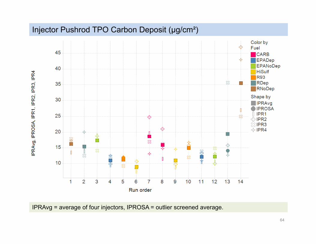
Injector Pushrod TPO Carbon Deposit (microgcmsup2)
Outlier Screened AverageOutlier Screened Average
Pairs of fuel with overlapping intervals were not significantly (α=005) different from each other
65
Outlier Screened Average
Injector Pushrod TPO Carbon Deposit (microgcmsup2)
Outlier Screened Averagere
sidu
als
uden
tized
S
tu
66
ConclusionsCo c us o s
Results from this scoping study did not confirm that p g yeither one of these rigs in their present state could discriminate among deposit forming and not deposit forming fuelsforming fuelsIf in-house work by either sponsor results in changes to provide differentiation CRC will consider further evaluationA new rig offered by Delphi is being considered
67
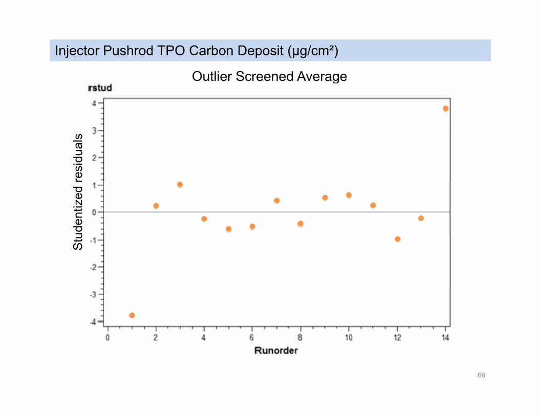