scr series - shiniusa.com · 1) scr series should be stored indoors with temperature kept from...
TRANSCRIPT

SCR Series PET Crystallizer
Date: Nov. 2014
Version: Ver.B (English)

3(56)
Contents
1. General Description .................................................................................. 7
1.1 Coding Principle ................................................................................... 8
1.2 Features............................................................................................... 8
1.3 Technical Specifications..................................................................... 10
1.3.1 Specifications ........................................................................... 10
1.3.2 Outline Drawing ........................................................................ 11
1.4 Safety Regulations ............................................................................. 12
1.4.1 Safety Signs and Labels ........................................................... 12
1.4.2 Transportation and Storage of the Machine.............................. 12
1.5 Exemption Clause.............................................................................. 13
2. Structure Characteristics and Working Principle ................................. 15
2.1 Working Principle ............................................................................... 15
2.2 Drawing and Parts List ....................................................................... 16
2.2.1 Assembly Drawing (SCR-160U) ............................................... 16
2.2.2 Parts List (SCR-160U).............................................................. 17
2.2.3 Assembly Drawing (SCR-450U/900U/1600U) .......................... 18
2.2.4 Parts List (SCR-450U/900U/1600U)......................................... 19
2.3 Electrical Diagram.............................................................................. 20
2.3.1 Main Circuit (SCR-160U) .......................................................... 20
2.3.2 Control Circuit (SCR-160U) ...................................................... 21
2.3.3 Thermocouple Wiring Diagram (SCR-160U) ............................ 22
2.3.4 Thermocouple and Terminal Layout (SCR-160U) .................... 23
2.3.5 Electrical Components List (SCR-160U) .................................. 24
2.3.6 Main Circuit (SCR-450U) .......................................................... 26
2.3.7 Control Circuit (SCR-450U) ...................................................... 27
2.3.8 Thermocouple and Terminal Layout (SCR-450U) .................... 28
2.3.9 Components Layout (SCR-450U)............................................. 29
2.3.10 Electrical Components List (SCR-450U)................................. 30
2.3.11 Main Circuit (SCR-900U~2500U) ........................................... 32
2.3.12 Control Circuit (SCR-900U~2500U)........................................ 36
2.3.13 Thermocouple and Terminal Layout (SCR-900U~2500U)...... 37

4(56)
2.3.14 Components Layout (SCR-900U~2500U) .............................. 38
2.3.15 Electrical Components List (SCR-900U~2500U) .................... 39
2.3.16 Main Electrical Components Description ................................ 45
3. Installation and Debugging..................................................................... 46
3.1 Installation of SCR ............................................................................. 46
4. Application and Operation...................................................................... 48
4.1 Description of Control Panel .............................................................. 48
4.2 Start / Stop of the Machine................................................................. 48
4.3 Operation of the Machine................................................................... 48
4.4 Main Operation Processes................................................................. 49
5. Trouble-shooting ..................................................................................... 50
6. Maintenance and Repair ......................................................................... 52
6.1 Filter ................................................................................................... 54
6.2 Blower ................................................................................................ 54
6.3 Maintenance Schedule....................................................................... 55
6.3.1 About the Machine.................................................................... 55
6.3.2 Check After Installation............................................................. 55
6.3.3 Daily Checking.......................................................................... 55
6.3.4 Weekly Checking...................................................................... 55
6.3.5 Monthly Checking ..................................................................... 55
6.3.6 Half-yearly Checking ................................................................ 55
Table Index
Table 1-1:Specifications................................................................................. 10
Table 2-1:Parts List (SCR-160U) ................................................................... 17
Table 2-2:Parts List (SCR-450U/1600U)........................................................ 19
Table 2-3:Electrical Components List (SCR-160U)........................................ 24
Table 2-4:Electrical Components List (SCR-450U)........................................ 30
Table 2-5:Electrical Components List (SCR-900U)........................................ 39
Table 2-6:Electrical Components List (SCR-1600U)...................................... 41
Table 2-7:Electrical Components List (SCR-2500U)...................................... 43

5(56)
Picture Index
Picture 1-1:Outline Drawing ........................................................................... 11
Picture 2-1:Working Principle......................................................................... 15
Picture 2-2:Assembly Drawing (SCR-160U) .................................................. 16
Picture 2-3:Assembly Drawing (SCR-450U/900U/1600U) ............................. 18
Picture 2-4:Main Circuit (SCR-160U) ............................................................. 20
Picture 2-5:Control Circuit (SCR-160U) ......................................................... 21
Picture 2-6:Thermocouple Wiring Diagram (SCR-160U)................................ 22
Picture 2-7:Thermocouple and Terminal Layout (SCR-160U)........................ 23
Picture 2-8:Main Circuit (SCR-450U) ............................................................. 26
Picture 2-9:Control Circuit (SCR-450U) ......................................................... 27
Picture 2-10:Thermocouple and Terminal Layout (SCR-450U)...................... 28
Picture 2-11:Components Layout (SCR-450U) .............................................. 29
Picture 2-12:Main Circuit 1 (SCR-900U~2500U)............................................ 32
Picture 2-13:Main Circuit 2 (SCR-900U) ........................................................ 33
Picture 2-14:Main Circuit 2 (SCR-1600U) ...................................................... 34
Picture 2-15:Main Circuit 2 (SCR-2500U) ...................................................... 35
Picture 2-16:Control Circuit (SCR-900U~2500U)........................................... 36
Picture 2-17:Thermocouple and Terminal Layout (SCR-900U~2500U) ......... 37
Picture 2-18:Components Layout (SCR-900U~2500U) ................................. 38
Picture 2-19:Overload Relay .......................................................................... 45
Picture 3-1:Installation of SCR ....................................................................... 46
Picture 3-2:Machine Ins Tallation Distance .................................................... 47

6(56)
7(56)
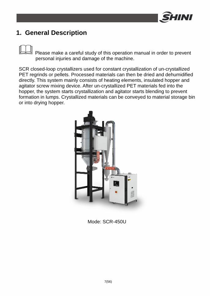
1. General Description
Please make a careful study of this operation manual in order to prevent personal injuries and damage of the machine.
SCR closed-loop crystallizers used for constant crystallization of un-crystallized PET regrinds or pellets. Processed materials can then be dried and dehumidified directly. This system mainly consists of heating elements, insulated hopper and agitator screw mixing device. After un-crystallized PET materials fed into the hopper, the system starts crystallization and agitator starts blending to prevent formation in lumps. Crystallized materials can be conveyed to material storage bin or into drying hopper.
Mode: SCR-450U

8(56)
1.1 Coding Principle
SCR- xxxU
Hopper Capacity (L)
Shini PET Crystallizers
European Type
Note*CE=CE Conformity
1.2 Features 1) Standard configuration
● Fixed speed of agitator makes materials not lump together during the crystallization.
● Simplify and improve drying efficiency. ● Materials can be dried under high temperature to improve drying efficiency. ● Cyclone dust collector is standard, which is applied to dust-rich place. Can
effectively reduce the load on return-air filter, and reduce the number of times of filter cleaning,thus extend the life span of the filter.
● With double overheat protectors, it can reduce the possibility of either mechanical or man-made problems.
● Equipped with rotary valve with good sealing performance, which can output crystallized material accurately.
● Equipped with material level switch, which can detect material level accurately and make operation reliable.
● Equipped with negative pressure tester to immediately test the ventilation of the filter. Give an alarm when the negative pressure is higher than the setting value, clean the filter to avoid blockage.
2) Accessory option
● Collocate with dehumidifier to fulfill dehumidification directly. ● Auto loader, hopper receiver, magnetic base, suction box are optional for
material conveying. ● Optional feed screw for stable and even conveying of uncrystallized material. ● External pipeline is optional with the stainless steel configuration.

9(56)
All service work should be carried out by a person with technical training or corresponding professional experience. The manual contains instructions for both handling and servicing. Chapter 6, which contains service instructions intended for service engineers. Other chapters contain instructions for the daily operator.
Any modifications of the machine must be approved by SHINI in order to avoid personal injury and damage to machine. We shall not be liable for any damage caused by unauthorized change of the machine.
Our company provides excellent after-sales service. Should you have any problem during using the machine, please contact the company or the local vendor.
Headquarter and Taipei factory: Tel: (886) 2 2680 9119 Shini Plastics Technologies (Dongguan), Inc: Tel: (86) 769 8111 6600 Shini Plastics Technologies India Pvt.Ltd.: Tel: (91) 250 3021 166

10(56)
1.3 Technical Specifications 1.3.1 Specifications
Table 1-1:Specifications
Model SCR-160U SCR-450U SCR-900U SCR-1600U SCR-2500U
Heater Power (kW) 12 24 48 96 128 Blower Power (kW) 0.55 / 0.63 2.2 / 2.6 3 / 3.6 7.5 / 8.6 15 / 17.2 Blending Motor Power (kW)
0.25 / 0.28 0.55 / 0.66 1.5 / 1.8 1.5 / 1.8 4 / 4.8
Max. Throughput (kg / hr) 50 150 300 500 750
Hopper Capacity (kg) 160 450 900 1600 2500
H(mm) 2380 3900 4450 5350 5600
H1(mm) 280 720 1040 860 1270
H2(mm) 380 1060 1185 1260 1270
W(mm) 1040 2370 2890 3570 4050
W1(mm) 1140 1440 1930 2190 2350
W2(mm) - 800 800 800 800
ФA(inch) 3 5 6 8 8
ФB(inch) 4 4 5 5 5
Weight (kg) 235 500 865 2290 2790 Note: 1) Above maximum processing capacity is based on uncrystallized PET material of 0.85kg/L in density
and 3~5mm in diameter. 2) Power: 3Φ, 230 / 400 / 460 / 575VAC, 50 / 60Hz.

11(56)
1.3.2 Outline Drawing
SCR-160U SCR-450U and above
Picture 1-1:Outline Drawing

12(56)
1.4 Safety Regulations
Note! Please abide by the safety guide when you operate the machine so as to prevent damage of the machine and personal injuries.
1.4.1 Safety Signs and Labels
All electrical components should be installed by qualified electricians. Turn off main switch and control switch during repair and maintenance.
Warning! High voltage! This mark is attached on the cover of the control box.
Warning! Be careful! Be more careful when this mark appears.
Attention! No need for regular inspection because all the electrical parts in the control unit are fixed tightly!
1.4.2 Transportation and Storage of the Machine
Transportation
1) SCR series are packed in crates or plywood cases with wooden pallet at the bottom, suitable for quick positioning by fork lift.
2) After unpacked, castors equipped on the machine can be used for ease of movement.
3) Do not rotate the machine and avoid collision with other objects during transportation to prevent improper functioning.
4) The structure of the machine is well-balanced, although it should also be handled with care when lifting the machine for fear of falling down.
5) The machine and its attached parts can be kept at a temperature from -25℃ to +55℃ for long distance transportation and for a short distance, it can be transported with temperature under +70℃.

13(56)
Storage 1) SCR series should be stored indoors with temperature kept from 5℃to 40℃
and humidity below 80%. 2) Disconnect all power supply and turn off main switch and control switch. 3) Keep the whole machine, especially the electrical components away from
water to avoid potential troubles caused by the water. 4) Plastic film should be used to protect the machine from dust and rains. Working environment Indoors in a dry environment with max. temperature +45℃and humidity no more than 80%. Do not use the machine 1) If it is with a damaged cord. 2) On a wet floor or when it is exposed to rain to avoid electrical shock. 3) If it has been dropped or damaged until it is checked or fixed by a qualified
serviceman. 4) This equipment works normally in the environment with altitude within 3000m. 5) At least a clearance of 1m surrounding the equipment is required during
operation. Keep this equipment away from flammable sources at least two meters.
6) Avoid vibration, magnetic disturbance at the operation area. Rejected parts disposal When the equipment has run out its life time and can not be used any more, unplug the power supply and dispose of it properly according to local code. Fire hazard
In case of fire, CO2 dry powder fire extinguisher should be applied. 1.5 Exemption Clause
The following statements clarify the responsibilities and regulations born by any buyer or user who purchases products and accessories from Shini (including employees and agents). Shini is exempted from liability for any costs, fees, claims and losses caused by reasons below:
1. Any careless or man-made installations, operation and maintenances upon

14(56)
machines without referring to the Manual prior to machine using. 2. Any incidents beyond human reasonable controls, which include man-made
vicious or deliberate damages or abnormal power, and machine faults caused by irresistible natural disasters including fire, flood, storm and earthquake.
3. Any operational actions that are not authorized by Shini upon machine, including adding or replacing accessories, dismantling, delivering or repairing.
4. Employing consumables or oil media that are not appointed by Shini.

15(56)
2. Structure Characteristics and Working Principle 2.1 Working Principle
Once material filling starts, heat blower starts up and material heating begins. Control cabinet would stop sending signals to auto loader when material filling amount is higher than material level switch. Then matreial heating lasts for a while. When temperature sensing needle detects the value of reaching the set crystallized temperature, material would be conveyed out via feeding device; meanwhile, as matreial level in hopper lowers gradually, filling device starts to supply the uncrystallized material accordingly to realize the continuous crystallization process. When temperature sensing needle detects the temperature value of stopping material conveying, feeding device halts. If temperature rises again to reach the set crystallized temperature, feeding device will be activated to work so that the continuous crystallization process can be realized through this kind of circle.
Picture 2-1:Working Principle

16(56)
2.2 Drawing and Parts List 2.2.1 Assembly Drawing (SCR-160U)
Remarks: Please refer to material list 2.2.2 for specific explanation of the Arabic numbers in
parts drawing.
Picture 2-2:Assembly Drawing (SCR-160U)

17(56)
2.2.2 Parts List (SCR-160U)
Table 2-1:Parts List (SCR-160U)
* means possible broken parts. ** means easy broken part. and spare backup is suggested. Please confirm the version of manual before placing the purchase order to guarantee that the item number of the spare part is in accordance with the real object.
No. Name Part No. No. Name Part No.
1 Rotary valve outlet adapter tube
- 16 Filter cloth bag BP82184500000
2 Hopper - 17 Cyclone dust collector
-
3 Sight glass - 18 Manual butterfly valve 3’’
YW59030000100
4 Mixer shaft assembly
YM10773700000 19 Dust collector material inlet flange
-
5 Storage tank - 20 Rotory valve SRV-4S
CG24000400150
6 Motor - 21 Floor stand -
7 Air exhaust - 22 Cleaning door -
8 Dust collector air inlet flange
- 23 Vacuum hopper adapter flange
-
9 Cyclone hopper - 24 Connection elbow -
10 3” stainless stell clamp
- 25 Filter barrel -
11 Cloth bag pipe - 26 Bower inlet flange -
12 Rotory material level sensor
YE15000200000 27 Blower 0.55kW BM30055000060
13 Pipe stator - 28 Outer case of the heating tank
-
14 3.5” stainless steel tube bundle
YW02003500000 29 Fixing plate of heating tank
-
15 3” heat-resisting air pipe
YW72033600100 30 Electrical control cabinet
-

18(56)
2.2.3 Assembly Drawing (SCR-450U/900U/1600U)
Remarks: Please refer to material list 2.2.4 for specific explanation of the Arabic numbers in
parts drawing.
Picture 2-3:Assembly Drawing (SCR-450U/900U/1600U)

19(56)
2.2.4 Parts List (SCR-450U/900U/1600U)
Table 2-2:Parts List (SCR-450U/1600U)
Part No. No. Name
SCR-450U SCR-900U SCR-1600U 1 Rotory vavle connecting pipe - - - 2 Rotory valve CG24000400150 CG24000500150 CG24000500150 3 Air outlet flange - - - 4 Mixer reduction gear * YM50538200800 YM50638200000 YM50638240000 5 SSC material inet flange - - - 6 Heating cabinet air inlet 2 - - - 7 Rotory level switch * YE15000200000 YE15000200000 YE15000200000 8 Heating cabinet assembly - - - 9 Heater BH70045000850 BH70090000950 BH70160000850
10 Stainless steel pipe bundle YW02501200000 YW02006500000 YW02008500000 11 Heat resistant air pipe YW72053600000 YW72060400000 YW72080400000 12 Hopper assembly - - - 13 Blending assembly - - - 14 Electrical control cabinet - - - 15 Blower stand - - -
16 Floor stand, guardail and laader assembly
- - -
17 Cloth bag clamp - - - 18 Filter cloth bag BP82206500044 BP82256500044 BP82851200244 19 Blower * BM30224000050 YM30304000000 YM30190500000 20 Filter barrel - - - 21 Filter * YR50241400100 YR50275700000 YR50275700000 22 Filter barrel fastener * YR10026000000 YR10034000000 YR10034000000 23 Sight glass assembly BH90000600050 BH90000600050 BH90000600050 24 Filter cloth bag pipe 2 - - - 25 Filter cloth bag pipe 1 - - - 26 Blower air outlet pipe 1 - - - 27 Stainless steel pipe stamp - - - 28 Blower air outlet pipe 2 - - - 29 Pipe fixing plate - - - 30 Cyclone dust separator - - - 31 Conntecting elbow 1 - - -
* means possible broken parts. ** means easy broken part. and spare backup is suggested. Please confirm the version of manual before placing the purchase order to guarantee that the item number of the spare part is in accordance with the real object.

20(56)
2.3 Electrical Diagram 2.3.1 Main Circuit (SCR-160U)
Picture 2-4:Main Circuit (SCR-160U)

21(56)
2.3.2 Control Circuit (SCR-160U)
Picture 2-5:Control Circuit (SCR-160U)

22(56)
2.3.3 Thermocouple Wiring Diagram (SCR-160U)
Picture 2-6:Thermocouple Wiring Diagram (SCR-160U)

23(56)
2.3.4 Thermocouple and Terminal Layout (SCR-160U)
Picture 2-7:Thermocouple and Terminal Layout (SCR-160U)

24(56)
2.3.5 Electrical Components List (SCR-160U)
Table 2-3:Electrical Components List (SCR-160U)
SCR-160U No. Symbol Name
Specification Material No. 1 Q1 Main switch* 25A 3P 690V 50/60Hz YE10210300000 2 Q2 Circuit breakers* 25A 3P 690V 50/60Hz YE40632500000
3 - Excitation break away* 230VAC YE40000900000
4 K1 Contactors* 9A 3P 1NO 230V 50/60Hz YE00301000000
5 K2 Contactors* 9A 3P 1NO 230V 50/60Hz YE00301000000
6 K3 Contactors* 9A 3P 1NO 230V 50/60Hz YE00301000000
7 K4 Contactors* 9A 3P 1NO 230V 50/60Hz YE00340000000
8 K5 K6 Temperature controller* E5EZ 100~240V 50/60Hz YE85005000000
9 K7 K8 K9 Middle relay 5A 2P 230V 50/60Hz YE03270700000
10 K10 Timer relay 230VAC 0~300h YE86300800000
11 F1 Overload relay* 1.25~2A 690V 50/60Hz YE01125200000
12 F2 Overload relay* 0.63~1A 690V 50/60Hz YE01063100000
13 F3 Overload relay* 0.63~1A 690V 50/60Hz YE01063100000
14 F4 Fuse** 6×30mm 2A 250V YE41001000000
15 T Transformer* IN=400V OUT=230V 500mA YE70402300800
16 PC PCB** 230VAC 50/60Hz YE80000100000
17 S1 S2 Control switch 4P WH YE10210400000
18 S3 Capacitive approach switch** 20~250VAC Sn:15mm YE15002000000
19 S4 Overheat protector 250V 5A YE21503000000
20 S5 S6 Thermocouple K TYPE BE90300000050
21 FM1 Fan* 230V 50/60Hz 120mm×120mm YM60121200400
22 X1 Terminal board 57A YE61060000000
23 - - - YE61063500000
24 - Terminal board 41A YE61040000000
25 - - - YE61043500000
26 X1 Terminal board 32A YE61250000000
27 - - - YE61253500000
28 - Terminal board 32A YE61250000000
29 - - - YE61253500000
30 X2 Terminal board 32A YE61250000000
31 X3 Terminal board 32A YE61250000000
32 - - - YE61253500000
33 X10 X11 Waterproof connectors - YE62163000100
34 M1 Blower* 0.55kW 400V 50Hz YM30055000000
35 M2 Motor** 0.25kW 400V 50Hz YM10673700000

25(56)
SCR-160U No. Symbol Name
Specification Material No. 36 M3 Motor* 0.18kW 400V 50Hz YM10371800000
37 EH1 Heater** 12kW 400v 50Hz BH70161200050 * means possible broken parts. ** means easy broken part. and spare backup is suggested. Please confirm the version of manual before placing the purchase order to guarantee that the item number of the spare part is in accordance with the real object.

26(56)
2.3.6 Main Circuit (SCR-450U)
Picture 2-8:Main Circuit (SCR-450U)

27(56)
2.3.7 Control Circuit (SCR-450U)
Picture 2-9:Control Circuit (SCR-450U)

28(56)
2.3.8 Thermocouple and Terminal Layout (SCR-450U)
Picture 2-10:Thermocouple and Terminal Layout (SCR-450U)

29(56)
2.3.9 Components Layout (SCR-450U)
Picture 2-11:Components Layout (SCR-450U)

30(56)
2.3.10 Electrical Components List (SCR-450U)
Table 2-4:Electrical Components List (SCR-450U)
SCR-450U No. Symbol Name
Specification Material No. 1 Q1 Main switch* 63A 3P 690V 50/60Hz YE10250400000 2 Q2 Circuit breakers* 50A 3P 690V 50/60Hz YE40635000000
3 - Excitation break away* 230VAC YE40000900000
4 Q3 Circuit breakers* 20A 3P 400V 50/60Hz YE40602000000
5 K1 Contactors* 9A 3P 1NO 230V 50/60Hz YE00301000000
6 K2 Contactors* 9A 3P 1NO 230V 50/60Hz YE00301000000
7 K3 Contactors* 9A 3P 1NO 230V 50/60Hz YE00301000000
8 K4 Contactors* 9A 3P 1NO 230V 50/60Hz YE00472200100
9 K5 K6 Temperature controller* E5EZ 100~240V 50/60Hz YE85005000000
10 K7 K8 K9 Middle relay 230V 50/60Hz YE03270700000
11 K10 Timer relay 230VAC 0~300h YE86300800000
12 F1 Overload relay* 4~6.3A 690V 50/60Hz YE01046300100
13 F2 Overload relay* 2~3.2A 690V 50/60Hz YE01023200000
14 F3 Overload relay* 0.63~1A 690V 50/60Hz YE01063100000
15 F4 Fuse** 6×30mm 2A 250V YE41001000000
16 T Transformer* IN=400V OUT=230V 500mA YE70402300800
17 PC PCB** 230VAC 50/60Hz YE80000100000
18 S1 S2 Control switch 4P WH YE10210400000
19 S3 Capacitive approach switch**
20~250VAC Sn:15mm YE15002000000
20 S4 Overheat protector* 250V 5A YE21503000000
21 S5 S6 Thermocouple K TYPE BE90400000050
22 FM1 Fan* 230V 50/60Hz YM60121200400
23 X1 Terminal board 76A YE61100000000
24 - - - YE61103500000
25 - Terminal board 32A YE61250000000
26 - - - YE61253500000
27 - Terminal board 32A YE61250000000
28 - - - YE61253500000
29 X2 Terminal board 32A YE61250000000
30 X3 Terminal board 32A YE61250000000
31 - - - YE61253500000
32 X10 Heavy duty connector 400V 5A YE68041000000 YE68041000100
33 X11 X12 Waterproof connectors - YE63314100000
34 X20 X21 Waterproof connectors 400V 16A YE63314100000

31(56)
SCR-450U No. Symbol Name
Specification Material No. 35 M1 Blower* 2.2kW 400V 50Hz BM30224000050
36 M2 Motor** 0.55kW 400V 50Hz YM50538200000
37 M3 Motor* 0.18kW 400V 50Hz YM10371800000
38 EH1 Heater** 24kW 400V 50Hz BH70045000850 * means possible broken parts. ** means easy broken part. and spare backup is suggested. Please confirm the version of manual before placing the purchase order to guarantee that the item number of the spare part is in accordance with the real object.

32(56)
2.3.11 Main Circuit (SCR-900U~2500U)
Picture 2-12:Main Circuit 1 (SCR-900U~2500U)

33(56)
Picture 2-13:Main Circuit 2 (SCR-900U)

34(56)
Picture 2-14:Main Circuit 2 (SCR-1600U)

35(56)
Picture 2-15:Main Circuit 2 (SCR-2500U)

36(56)
2.3.12 Control Circuit (SCR-900U~2500U)
Picture 2-16:Control Circuit (SCR-900U~2500U)

37(56)
2.3.13 Thermocouple and Terminal Layout (SCR-900U~2500U)
Picture 2-17:Thermocouple and Terminal Layout (SCR-900U~2500U)

38(56)
2.3.14 Components Layout (SCR-900U~2500U)
Picture 2-18:Components Layout (SCR-900U~2500U)
39(56)
2.3.15 Electrical Components List (SCR-900U~2500U)
Table 2-5:Electrical Components List (SCR-900U)
SCR-900U No. Symbol Name
Specification Material No. 1 Q1 Main switch* 16A 3P 690V 50/60Hz YE10200300000 2 Q2 Circuit breakers* 25A 3P 690V 50/60Hz YE40602500000
3 Q3 Gate circuit breakers* 90A 3P 690V 50/60Hz YE41109000000
4 - Excitation break away* SOR-C 230VAC YE40101600000
5 K1 Contactors* 9A 3P 1NO 230V 50/60Hz YE00301000000
6 K2 Contactors* 9A 3P 1NO 230V 50/60Hz YE00301000000
7 K3 Contactors* 9A 3P 1NO 230V 50/60Hz YE00301000000
8 K4 K5 K6 Contactors* 9A 3P 1NO 230V 50/60Hz YE00350000000
9 K9 Timer relay 3S~60M 230VAC YE86300300000
10 K10 K15 Middle relay* 5A 2P 230V 50/60Hz YE03270700000
11 K11 K12 Temperature controller E5EZ 100~240V 50/60Hz YE85005000000
12 K13 Timer relay 230VAC 0~300h YE86300800000
13 F1 Overload relay* 5~8A 690V 50/60Hz YE01050800000
14 F2 Overload relay* 3.2~5A 690V 50/60Hz YE01032500000
15 F3 Overload relay* 0.63~1A 690V 50/60Hz YE01063100000
16 F4 Fuse** 6×30mm 2A 250V YE41001000000
17 T Transformer* IN=400V OUT=230V 800mA YE70402300900
18 PC PCB* 230VAC 50/60Hz YE80000100000
19 S1 S2 Control switch 4P WH YE10210400000
20 S3 Capacitive approach switch* 20~250VAC Sn:15mm YE15002000000
21 S4 Overheat protector* 250V 5A YE21503000000
22 S5 S6 Thermocouple K BE90600000050
23 FM1 Fan* 230V 50/60Hz 120mm×120mm YM60121200400
24 X1 Terminal board 32A YE61250000000
25 - - - YE61253500000
26 X1 Terminal board 32A YE61250000000
27 - - - YE61253500000
28 X2 Terminal board 32A YE61250000000
29 - - - YE61253500000
30 X3 Terminal board 32A YE61250000000
31 X10 Heavy duty connector 400V 5A YE68161600000
32 X11 x12 Waterproof connectors - YE62163000100
33 X20 21 Waterproof connectors 400V 16A YE63314100000
34 M1 Blower* 3kW 400V 50Hz YM30304000000
35 M2 Motor** 1.5kW 400V 50Hz YM50101200100
36 M3 Motor** 0.18kW 400V 50Hz YM10206300000
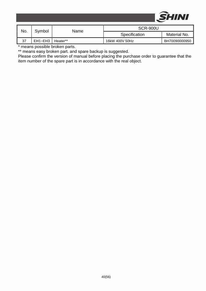
40(56)
SCR-900U No. Symbol Name
Specification Material No. 37 EH1~EH3 Heater** 16kW 400V 50Hz BH70090000950
* means possible broken parts. ** means easy broken part. and spare backup is suggested. Please confirm the version of manual before placing the purchase order to guarantee that the item number of the spare part is in accordance with the real object.

41(56)
Table 2-6:Electrical Components List (SCR-1600U)
SCR-1600U No. Symbol Name
Specification Material No. 1 Q1 Main switch* 25A 3P 690V 50/60Hz YE10210300000
2 Q2 Circuit breakers* 40A 3P 690V 50/60Hz YE40101600000
3 Q3 Gate circuit breakers* 200A 3P 690V 50/60Hz YE41252000000
4 - Excitation break away* SOR-C 230VAC YE40101600000
5 K1 Contactors* 22A 3P 1NO+1NC230V 50/60Hz YE00331100000
6 K2 Contactors* 9A 3P 1NO 230V 50/60Hz YE00301000000
7 K3 Contactors* 9A 3P 1NO 230V 50/60Hz YE00301000000
8 K4 K5 K6 K7 K8
Contactors* 45A 3P 2NO+2NC 230V 50/60Hz YE00462200100
9 K9 Timer relay 3S~60M 230VAC YE86300300000
10 K10 K15 Middle relay* 5A 2P 230V 50/60Hz YE03270700000
11 K11 K12 Temperature controller 100~240V 50/60Hz YE85005000000
12 K13 Timer relay 230VAC 0~300h YE86300800000
13 F1 Overload relay* 12.5~20A 690V 50/60Hz YE01125200100
14 F2 Overload relay* 3.2~5A 690V 50/60Hz YE01032500000
15 F3 Overload relay* 0.63~1A 690V 50/60Hz YE01063100000
16 F4 Fuse** 6×30mm 2A 250V YE41001000000
17 T Transformer* IN=400V OUT=230V 1000mA YE70402300000
18 PC PCB* 230VAC 50/60Hz YE80000100000
19 S1 S2 Control switch 4P WH YE10210400000
20 S3 Capacitive approach switch*
20~250VAC Sn:15mm YE15002000000
21 S4 Overheat protector* 250V 5A YE21503000000
22 S5 S6 Thermocouple K BE90600000050
23 FM1 Fan* 230V 50/60Hz YM60121200400
24 X1 Terminal board 57A YE61060000000
25 - - - YE61063500000
26 X1 Terminal board 41A YE61040000000
27 - - - YE61043500000
28 - Terminal board 32A YE61250000000
29 - - - YE61253500000
30 - Terminal board 32A YE61250000000
31 - - - YE61253500000
32 X2 Terminal board 32A YE61250000000
33 - - - YE61253500000
34 X3 Terminal board 32A YE61250000000
35 X10 Heavy duty connector 400V 5A YE68161600000
36 X11 x12 Waterproof connectors - YE62163000100

42(56)
SCR-1600U No. Symbol Name
Specification Material No. 37 X20 X21 Waterproof connectors 400V 16A YE63314100000
38 S7 Magnetic switch 250V 5A YE15184200000 YE15184200100
39 M1 Blower* 7.5kW 400V 50Hz YM30190500000
40 M2 Motor 1.5kW 400V 50Hz YM50101200100
41 M3 Motor 0.18kW 400V 50Hz YM10206300000
42 EH1~EH5 Heater* 19.2kW 400V 50Hz BH70160000850 * means possible broken parts. ** means easy broken part. and spare backup is suggested. Please confirm the version of manual before placing the purchase order to guarantee that the item number of the spare part is in accordance with the real object.

43(56)
Table 2-7:Electrical Components List (SCR-2500U)
SCR-2500U No. Symbol Name
Specification Material No. 1 Q1 Main switch* 63A 3P 690V 50/60Hz YE10250400000
2 Q2 Circuit breakers* 80A 3P 690V 50/60Hz YE40800300000
3 Q3 Gate circuit breakers* 250A 3P 690V 50/60Hz YE41252500000
4 - Excitation break away* SOR-C 230VAC YE40101600000
5 K1 Contactors* 22A 3P 1NO+1NC230V 50/60Hz YE00351100100
6 K2 Contactors* 9A 3P 1NO 230V 50/60Hz YE00301000000
7 K3 Contactors* 9A 3P 1NO 230V 50/60Hz YE00301000000
8 K4 K5 K6 K7 K8
Contactors* 45A 3P 2NO+2NC 230V 50/60Hz YE00472200100
9 K9 Timer relay 3S~60M 230VAC YE86300300000
10 K10 K15 Middle relay* 5A 2P 230V 50/60Hz YE03270700000
11 K11 K12 Temperature controller 100~240V 50/60Hz YE85005000000
12 K13 Timer relay 230VAC 0~300h YE86300800000
13 F1 Overload relay* 25~36A 690V 50/60Hz YE01253600200
14 F2 Overload relay* 4~6.3A 690V 50/60Hz YE01046300100
15 F3 Overload relay* 0.63~1A 690V 50/60Hz YE01063100000
16 F4 Fuse** 6×30mm 2A 250V YE41001000000
17 T Transformer* IN=400V OUT=230V 1500mA YE70402300300
18 PC PCB* 230VAC 50/60Hz YE80000100000
19 S1 S2 Control switch 4P WH YE10210400000
20 S3 Capacitive approach switch* 20~250VAC Sn:15mm YE15002000000
21 S4 Overheat protector* 250V 5A YE21503000000
22 S5 S6 Thermocouple K -
23 FM1 Fan* 230V 50/60Hz YM60121200400
24 X1 Terminal board 76A YE83050200100
25 - - - YE61103500000
26 X1 Terminal board 57A YE61060000000
27 - - - YE61063500000
28 - Terminal board 32A YE61250000000
29 - - - YE61253500000
30 - Terminal board 32A YE61250000000
31 - - - YE61253500000
32 X2 Terminal board 32A YE61250000000
33 - - - YE61253500000
34 X3 Terminal board 32A YE61250000000
35 X10 Heavy duty connector 400V 5A YE68161600000
36 X11 x12 Waterproof connectors - YE62163000100

44(56)
SCR-2500U No. Symbol Name
Specification Material No. 37 X20 X21 Waterproof connectors 400V 16A YE63314100000
38 S7 Magnetic switch 250V 5A YE15184200000 YE15184200100
39 M1 Blower* 15kW 400V 50Hz -
40 M2 Motor 2.2kW 400V 50Hz -
41 M3 Motor 0.18kW 400V 50Hz -
42 EH1~EH5 Heater* 26.8kW 400V 50Hz - * means possible broken parts. ** means easy broken part. and spare backup is suggested. Please confirm the version of manual before placing the purchase order to guarantee that the item number of the spare part is in accordance with the real object.

45(56)
2.3.16 Main Electrical Components Description Overload Relay At delivery, the overload relay is set for manual reset. (the reset button pointing to H). Manually reset the relay at the tripping of the switch. When motor overload occurs, stop the machine, then check and solve the problem. After that open the door of control box, press down the reset button of overload relay (if you can not press down the reset button, wait for one minute).
①
②
③
④
⑤
⑥
⑥
⑦
Picture 2-19:Overload Relay
1) Terminal for contact coil A2. 2) Setting current adjusting scale. 3) Reset (blue). H: manual reset A: automatic reset 4) Switch position indication (green).
Tripping of a manual-resetting is indicated by a pin projecting from the front plate.
5) Test button (red). 6) Auxiliary contact terminals shown in 95.96.97.98. NC and NO contacts are
shown in position 95.96. and 97.98. respectively. 7) Main circuit connection No. must be correspond with terminal Number of
contactor.

46(56)
3. Installation and Debugging Before installation, please read the this chapter. Install the machine by the following steps!
Power supply should be fixed by professional technicians only!
3.1 Installation of SCR
Picture 3-1:Installation of SCR
Power Supply Make sure that the power supply conforms with required specifications before installation. SCR series are generally set to be used with 3Φ400VAC 50Hz power supply or other specifications if required.

47(56)
Picture 3-2:Machine Ins Tallation Distance
Note! Keep the machine 1M from the combustible distance.

48(56)
4. Application and Operation 4.1 Description of Control Panel
4.2 Start / Stop of the Machine The start / stop of the machine is controlled by the system switch on the control panel.
4.3 Operation of the Machine 1) Turn on the main power switch. 2) Set the temperature of regenerating and return air. (Set regenerating
temperature at 160℃, and return air temperature at 93℃). 3) Turn on the system switch, and the machine starts working.

49(56)
4.4 Main Operation Processes 1) Connect the power supply: connect the three-phase power and open the
main power switch, and then, the power indicator in the control panel is blinking and shows the power is on. If there is converse-alarm, please cut off the power supply, and use double power supply lines to instead of the previous one. Then, follow the foregoing instructions, redo the operations.
2) Press switch S1, the system goes into the working condition. After the temperature controller indicates the power on, agitator begins to work. The control box will send out a signal to material suction motor to fill up the hopper. (Use crystallized material every time you start the machine). When the material level reaches the level sensor, control box will stop materials feeding.
3) Set the temperature controller: 1. Temperature controller (K10) measures the vent temperature of the crystallizer. Set the alarm 1 of K10 to 'the upper limit alarm', the alarming value is 0 ; Set the alarm 2 to 'the upper limit alarm', ℃
and the alarming value is -22 ; Set 93 to the setting temperature of the ℃ ℃
temperature controller K10. (These settings control discharging. When the temperature reached 93 , crystallizer will begin to discharge materials; ℃
when the temperature is under 71 , discharging will be stopped ); 2. ℃
Temperature controller (K8): setting temperature is 160 (the inlet ℃
temperature of crystallizer). 4) Press switch button S2 for heating up material. After one hour, open the
switch of material discharging motor. When the temperature of return air comes to 93℃ (200oF), the control box will send a signal to material discharging motor for discharging. As soon as material discharging begins, material level lowers, which will set material level sensor in motion. Material suction motor will then begin adding uncrystallized material. Afterwards the crystallizer starts a continuous process of material crystallizing.
5) At the time when discharged material is too much than materials loaded. That means there is not enough time for material crystallizing, which will lead to a drop of return air temperature. When return air temperature reduces to 71℃ (160oF), the control box will stop material discharge motor which will be started again when return air temperature reaches 93℃ (200oF).
6) Before stopping the crystallizer, please turn off the material suction motor first. Discharging materials only after they are crystallized.

50(56)
5. Trouble-shooting Fault Possible reasons Solution
It doesn't start after turning on the main switch.
Disconnect from the power supply. Power switch is broken. Power cable is fault. The fuse of control electricity line is broken. Control transformer is broken.
Connect to the power supply. Change the power supply switch. Check the lines of power. Change the fuse after checking the lines. Change the transformer.
After turning on the power supply switch, the power supply indication light is on, but the reverse phase indication light is also on and the buzzer sounds an alarm.
The voltage of power supply is too low. Lack of phase. The connective phase sequence is wrong.
Check the power supply. Exchange the position of any two input lines of power supply.
The rotation motor cannot run.
Contactor of rotation motor is fault. Rotation motor is fault. Circuit is fault.
Change the contactor. Check and change the motor. Check the circuit.
The crystallizer is not full, but the material compensation and absorption machine cannot run; or crystallizer is full, but the material compensation and absorption machine cannot stop.
Electricity lines are fault. Capacitance switch are not adjusted properly or fault.
Check the lines. Adjust the capacitance switch or change it.
The crystallizer doesn't unload materials for a long time, or unloads before the materials are crystallized.
Check the setting of the temperature control meter. Lines fault. Other reasons.
Temperature controller K10 detects the air-outlet's humidity of the crystallizer. Set the K10 alarm 1 to 00C, alarm 2 to 'the last line alarm', and its alarm value is -220C. the setting temperature of K10 is 930C. Temperature controller K8 detects the air-outlet's temperature of the crystallizer, and the setting value is 1600C.
Not turn on main switch or system switch or poor connection of the switches.
Turn on the main switch or system switch or reconnect the switches.
Problems of material level switch.
Adjust or replace. Motor does not work long after material discharged.
Broken of signal wire. Reconnect.
Motor continues working after hopper full loaded.
Contactor problems. Repair or replace contactor.

51(56)
Fault Possible reasons Solution
Material has used up. Add new material.
Leakage in the conveying hose. Lock tight the hose or replace. Can not full load the hopper for several times or material shortage alarm lit up.
Blocking of filter screen. Clean the filter screen.
Motor failures Phase shortage or motor burnt out.
Check or replace.
Fuse melts when turn on the machine.
Short circuit or motor burnt out. Check the circuit.
Blocking of filter.
Clean the filter and press Reset on
the overload relay. Motor overload alarm lit up.
Short of phase.
Press Reset on the overload relay
after check the circuit.

52(56)
6. Maintenance and Repair Clear off the dust on the motor fan regularly; avoid the damage to the blower.
SCR-160U

53(56)
SCR-450U and Models Above

54(56)
6.1 Filter Regulary clean the filter. (Once a week)
Cleaning steps:
1) Take out the filter.
2) Use compressed air to clean the filter cover and filter.
3) Use clean rag to clean the inner wall of the barrel.
4) Reinstall the filter after cleaning.
Note: Do not let any impurities fall into the filter barrel when you take out the filter.
6.2 Blower 1) Clear up inside and outside of the blower at times. If there are too much dirts
accumulated on the blower, the function of the blower will be affected, such as temperature rising, reduced air volume and higher noise level due to vibration. All the above factors are liable to cause mechanical problems.
2) The bearing, seal ring and silencer are all consumable parts. They should be replaced after a period of time. And also the fans, covers, and metal grids need to be changed when necessary.

55(56)
6.3 Maintenance Schedule 6.3.1 About the Machine
Model SN Manufacture date
Voltage Ф V Frequency Hz Power kW
6.3.2 Check After Installation
Check that the conveying pipes are tightly locked.
Check that the material clearance door is firmly closed.
Check that the conveying pipes are correctly connected.
Electrical Installation
Voltage: V Hz
Fuse melting current:One-phase: A Three-phase: A
Check the phase frequency of power supply.
Check rotating direction of the blower.
6.3.3 Daily Checking
Check the switches of the machine. Check the performance of the machine.
6.3.4 Weekly Checking
Check all the electrical wires. Check if there are loose electrical connections. Check and clean air filter. Check solenoid valve. Check motor overload relay.
6.3.5 Monthly Checking
Check that the pipe heater is working properly. Check the performance of blower. Check the functions of electrical components.
6.3.6 Half-yearly Checking
Check if there are damages of heat-resistant hose or not. Check the process heater.

56(56)
Check the blower.