screenmanager for small human machine interfaces
TRANSCRIPT

Application Description
DOK-SUPPL*-SCM*BEDIEN*-AW02-EN-P
SYSTEM200
SCREENMANAGERfor Small Human Machine Interfaces
About this Documentation SCM-Application Description
DOK-SUPPL*-SCM*BEDIEN*-AW02-EN-P
Screenmanager for Small Human Machine Interfaces
Application Description
DOK-SUPPL*-SCM*BEDIEN*-AW02-EN-P
• Document number: 120-2100-B311-03/EN
The following documentation describes
• the handling of the Software
• the funktion of the Software
• the explanation of parameter settings of the controls
Document identification of previ-ous and present output
ReleaseDate
Comments
120-2100-B311-01/EN 10/99 First issue
120-2100-B311-02/EN 05/00 Revision
120-2100-B311-02/EN 04/01 Extension
REXROTH INDRAMAT GmbH, 2001
Transmission as well as reproduction of this documentation, commercialuse or communication of its contents will not be permitted without ex-pressed written permission. Violation of these stipulations will requirecompensation. All rights reserved for the issuance of the patent or regis-tered design. (DIN 34-1)
All rights are reserved with respect to the content of this documentationand the availability of the product.
REXROTH INDRAMAT GmbHBgm.-Dr.-Nebel-Str. 2 • D-97816 Lohr a. Main
Telephone 09352/40-0 • Tx 689421 • Fax 09352/40-4885
http://www.rexroth.com/indramat
Dept. ECH2
This document has been printed on chlorine-free bleached paper.
Title
Type of documentation
Documentation code
Internal file reference
What is the purpose of thisdocument?
Course of modifications
Copyright
Validity
Published by
Note
SCM-Application Description Contents I
DOK-SUPPL*-SCM*BEDIEN*-AW03-EN-P
Contents
1 General 1-1
1.1 Purpose of the document ............................................................................................................... 1-1
1.2 Related publications....................................................................................................................... 1-1
1.3 Brief description ............................................................................................................................. 1-1
2 Parameter Setup 2-1
2.1 Call the Parameter Setup............................................................................................................... 2-1
2.2 Setting the Contrast ....................................................................................................................... 2-1
2.3 Exiting Parameter Setup ................................................................................................................ 2-1
2.4 Handling and Operation ................................................................................................................. 2-2
Menu structure ......................................................................................................................... 2-2
2.5 Parameters of the Serial Interfaces ............................................................................................... 2-2
Intelligent Defaults ................................................................................................................... 2-3
Serial ports 1/2......................................................................................................................... 2-3
Serial status ............................................................................................................................. 2-4
COM1<>COM2 Relay mode.................................................................................................... 2-4
2.6 System Parameters........................................................................................................................ 2-5
2.7 Password Structure........................................................................................................................ 2-6
2.8 Flash Status ................................................................................................................................... 2-8
Attributes ................................................................................................................................ 2-10
Reading and loading file systems via Dolfi ............................................................................ 2-11
3 Firmware Download Tool Dolfi 3-1
3.1 The Dolfi User Interface ................................................................................................................. 3-1
3.2 Reading Out Modules .................................................................................................................... 3-2
4 Typical Applications for Indramat Controllers 4-1
4.1 Hardware Requirements ................................................................................................................ 4-1
5 BTV04 with DKC03 5-1
5.1 Device settings............................................................................................................................... 5-1
Setting the baud rate................................................................................................................ 5-1
Using the I/O mapper files ....................................................................................................... 5-1
Mode-specific settings ............................................................................................................. 5-2
5.2 Program Description ...................................................................................................................... 5-3
Overview of BTV keys.............................................................................................................. 5-3
Handling the BTV unit .............................................................................................................. 5-4

II Contents SCM-Application Description
DOK-SUPPL*-SCM*BEDIEN*-AW03-EN-P
5.3 Menu .............................................................................................................................................. 5-5
Main menu ............................................................................................................................... 5-5
Mode ........................................................................................................................................ 5-6
Change mode ........................................................................................................................ 5-10
Parameters ............................................................................................................................ 5-11
Commands............................................................................................................................. 5-15
Phase selection...................................................................................................................... 5-15
6 BTV04 Unit with Ecodrive03 FLP 6-1
6.1 Introduction..................................................................................................................................... 6-1
Purpose of the program ........................................................................................................... 6-1
Additional functionalities .......................................................................................................... 6-1
6.2 Device Settings .............................................................................................................................. 6-2
Explanation .............................................................................................................................. 6-2
Communication initialization .................................................................................................... 6-2
6.3 Program Description ...................................................................................................................... 6-5
Navigation and handling .......................................................................................................... 6-5
Menu ........................................................................................................................................ 6-6
Display menu ........................................................................................................................... 6-6
System keys and inputs/outputs on the BTV04 unit .............................................................. 6-14
Pass-through operation.......................................................................................................... 6-15
7 BTV04 with Visual Motion (GPS 6, 7 and GPP7) 7-1
7.1 Device Settings .............................................................................................................................. 7-1
Firmware/Software Requirements ........................................................................................... 7-1
BTV04 Communication Settings.............................................................................................. 7-1
CLC / PPC-R Communication Settings ................................................................................... 7-2
BTV04 Serial Port Settings: ..................................................................................................... 7-2
Visual Motion Parameter and Program Requirements ............................................................ 7-3
7.2 General BTV04 Operation.............................................................................................................. 7-4
Key Definitions ......................................................................................................................... 7-4
LED Definitions ........................................................................................................................ 7-5
7.3 Sample Program Screen Descriptions........................................................................................... 7-6
Main Menu Screen................................................................................................................... 7-6
System Info/Status Menu Screen ............................................................................................ 7-6
Variable Type Selection Screen............................................................................................... 7-7
I/O Register Screen ................................................................................................................. 7-8
Parameter Menu Screen.......................................................................................................... 7-8
Program Management Menu Screen....................................................................................... 7-9
Jogging Screen ...................................................................................................................... 7-10
7.4 Problem Solving ........................................................................................................................... 7-11
Checking for Communications............................................................................................... 7-11
Serial Errors ........................................................................................................................... 7-11
Unable to Enter Jog Screen................................................................................................... 7-11
SCM-Application Description Contents III
DOK-SUPPL*-SCM*BEDIEN*-AW03-EN-P
8 BTV04/05/06, BTC06 with MTC200-P or MTC200-R 8-1
8.1 Hardware Requirements ................................................................................................................ 8-1
BTV05/06.x or BTC06 with MTC200-P.................................................................................... 8-1
BTV05/06.x or BTC06 with MTC200-R.................................................................................... 8-1
BTV04 with MTC200-P ............................................................................................................ 8-1
BTV04 with MTC200-R ............................................................................................................ 8-1
8.2 Preparing the Typical Application .................................................................................................. 8-2
8.3 Parameter Value Assignment of BTV04/05/06 and BTC06........................................................... 8-3
8.4 BTxx Function Block ...................................................................................................................... 8-4
Task ......................................................................................................................................... 8-4
Function block structure........................................................................................................... 8-4
FB inputs .................................................................................................................................. 8-4
FB outputs................................................................................................................................ 8-5
Structures and variables .......................................................................................................... 8-6
Parameter value assignment of the BTxx communication function block ............................. 8-12
8.5 No Communication! What Shall Be Done?.................................................................................. 8-14
8.6 Program Description .................................................................................................................... 8-14
Handling the small operator input units ................................................................................. 8-14
Keys of the small operator input units.................................................................................... 8-15
Main menu ............................................................................................................................. 8-16
F1 - Start conditions............................................................................................................... 8-16
F2 - Diagnosis........................................................................................................................ 8-17
F3 – Operator input................................................................................................................ 8-17
F5 – NC functions (BTC06 and BTV06 only)......................................................................... 8-18
8.7 Output of ProVi Diagnoses........................................................................................................... 8-20
8.8 Output of System Errors and Mechanism Messages .................................................................. 8-22
Requirements......................................................................................................................... 8-22
System errors......................................................................................................................... 8-22
Mechanism errors and mechanism messages ...................................................................... 8-23
9 BTC06 with DLC01.1 9-1
9.1 Device settings............................................................................................................................... 9-1
Basic settings on the BTC06 unit............................................................................................. 9-1
DLC settings............................................................................................................................. 9-1
9.2 Summary of the Major Points......................................................................................................... 9-2
BTC06 port selections:............................................................................................................. 9-2
DLC parameters....................................................................................................................... 9-2
ScreenManager ....................................................................................................................... 9-2
9.3 Program Description ...................................................................................................................... 9-3
Loading DLC program blocks .................................................................................................. 9-3
Navigation and Handling.......................................................................................................... 9-4
Menu ........................................................................................................................................ 9-5
10 System Messages 10-1
10.1 The ScreenManager Does not Start ............................................................................................ 10-1
10.2 The Application Does not Start .................................................................................................... 10-1
IV Contents SCM-Application Description
DOK-SUPPL*-SCM*BEDIEN*-AW03-EN-P
10.3 Start Messages ............................................................................................................................ 10-1
Flash Fail................................................................................................................................ 10-2
Load default, parameter rewritten.......................................................................................... 10-2
Section x bad use y, parameter rewritten .............................................................................. 10-2
Wrong parameter version ...................................................................................................... 10-2
Illegal COMx parameters ....................................................................................................... 10-2
Flash Erase Error................................................................................................................... 10-3
10.4 Error Messages During Operation ............................................................................................... 10-3
CNC telegram not supported ................................................................................................. 10-3
EEPROM erase time-out ....................................................................................................... 10-3
EEPROM write time-out......................................................................................................... 10-3
Fatal ReadMiniMapString ...................................................................................................... 10-3
Fatal LoadProViData.............................................................................................................. 10-3
Flash write error ..................................................................................................................... 10-4
Handle was not valid.............................................................................................................. 10-4
Insert line not supported ........................................................................................................ 10-4
Map file create error............................................................................................................... 10-4
Map file write error ................................................................................................................. 10-4
MTC-Longident wrong size .................................................................................................... 10-4
No ASCII port for CLC ........................................................................................................... 10-4
No ASCII port for CLM........................................................................................................... 10-5
No more list handles .............................................................................................................. 10-5
No more list memory.............................................................................................................. 10-5
No SIS master port for ELC ................................................................................................... 10-5
No SIS master port for DKC................................................................................................... 10-6
No SIS master port for ELC, no real-time connection ........................................................... 10-6
Not enough RAM for list buffers............................................................................................. 10-6
Only parameter not implemented .......................................................................................... 10-6
Parameter write fail ................................................................................................................ 10-7
Serial recursive call................................................................................................................ 10-7
Wrong list handle r ................................................................................................................. 10-7
Wrong list handle w................................................................................................................ 10-7
Wrong read offset from CNC ................................................................................................. 10-7
10.5 Script Execution Errors ................................................................................................................ 10-7
Array overflow ........................................................................................................................ 10-7
Bp underflow .......................................................................................................................... 10-7
Divided by 0 ........................................................................................................................... 10-7
Illegal segment....................................................................................................................... 10-7
Jump out of segment ............................................................................................................. 10-8
Out of segment ...................................................................................................................... 10-8
Stack overflow........................................................................................................................ 10-8
Stack underflow ..................................................................................................................... 10-8
R-stack overflow .................................................................................................................... 10-8
Unknown opcode ................................................................................................................... 10-8
Unknown system call ............................................................................................................. 10-8
SCM-Application Description Contents V
DOK-SUPPL*-SCM*BEDIEN*-AW03-EN-P
10.6 Script Execution Error - Fatal I/O Error ........................................................................................ 10-9
IO elc string too long .............................................................................................................. 10-9
Illegal IO access..................................................................................................................... 10-9
PLC variable unknown ........................................................................................................... 10-9
No more edit cells .................................................................................................................. 10-9
No more serial buffers.......................................................................................................... 10-10
Type not supported .............................................................................................................. 10-10
Variable must be global ....................................................................................................... 10-10
Wrong map file entry............................................................................................................ 10-10
Wrong PLC answer length ................................................................................................... 10-10
10.7 I/O Error Window........................................................................................................................ 10-11
CLC is not responding ......................................................................................................... 10-11
CLM is not responding ......................................................................................................... 10-11
CNC answer too short.......................................................................................................... 10-11
CNC NAK xx yy.................................................................................................................... 10-11
Ecodrive Error 0xNNNN....................................................................................................... 10-12
Ecodrive is not responding................................................................................................... 10-12
DKC answer too long ........................................................................................................... 10-12
DKC answer too short.......................................................................................................... 10-12
DKC wrong answer .............................................................................................................. 10-12
10.8 FLASH Lifetime Warning............................................................................................................ 10-12
11 List of Figures 11-1
12 Index 12-1
13 Service & Support 13-1
13.1 Helpdesk ...................................................................................................................................... 13-1
13.2 Service-Hotline............................................................................................................................. 13-1
13.3 Internet ......................................................................................................................................... 13-1
13.4 Vor der Kontaktaufnahme... - Before contacting us..................................................................... 13-1
13.5 Kundenbetreuungsstellen - Sales & Service Facilities ................................................................ 13-2

VI Contents SCM-Application Description
DOK-SUPPL*-SCM*BEDIEN*-AW03-EN-P

SCM-Application Description General 1-1
DOK-SUPPL*-SCM*BEDIEN*-AW03-EN-P
1 General
1.1 Purpose of the document
This description of the screen manager runtime shall explain the handlingof the small operator input units and inform the user of possible settingsthat can be made via a parameter setup. In addition, it provides details oftypical applications for the connection to Indramat controllers, includingthe related parameter settings and controller-specific functions, addressassignments etc. that are required for commissioning.
1.2 Related publications
Unit/accessories Documentation name Comment
BTV04 Configuration DOK-SUPPL*-BTV04.2****
BTV05 Configuration DOK-SUPPL*-BTV05.2****
BTV06 Configuration DOK-SUPPL*-BTV06.1****
BTC06 Configuration DOK-SUPPL*-BTC06******
Hardware description including technical specifica-tions, outside dimensions, connections, programdownload via Dolfi, accessories, cables, typical con-nections of Indramat controllers, etc.
ScreenManager DOK-SUPPL*-SCM*PROG*** Description of the ScreenManager PC programmingdesktop including installation, handling and explana-tion of the programming language.
Fig. 1-1: Related publications
1.3 Brief description
ScreenManager Runtime (SWA-SCM03VRS) is a kind of "operating sys-tem" that is required for being able to perform configurations on smalloperator input units (such as the BTV04/05/06 unit or the manual controlunit BTC06). The parameter setup can be used for making selections thatare important for the handling of the miniature control panels and for thecommunication between them and other units.

1-2 General SCM-Application Description
DOK-SUPPL*-SCM*BEDIEN*-AW03-EN-P
SCM-Application Description Parameter Setup 2-1
DOK-SUPPL*-SCM*BEDIEN*-AW03-EN-P
2 Parameter Setup
2.1 Call the Parameter Setup
There are three possibilities of calling the Parameter Setup:
• With a unit that has not yet been loaded with other projects, the Pa-rameter Setup automatically appears on the display when the unit isswitched on.
• With a unit that contains a project, F2 must be pressed when the unitis switched on in order to call the Parameter Setup.
• The Parameter Setup may also be called from a project that has al-ready been started. This requires a key to be linked with the systemcall "ParameterScreen()".
2.2 Setting the Contrast
Parameter SetupF1-Serial Port ParameterF2-System ParameterF3-Save Values and RebootF4-Exit without Changes
Set LCD Contrast
Start_Screen.FH7
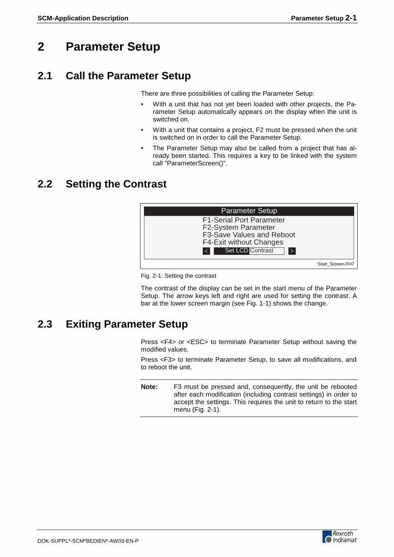
Fig. 2-1: Setting the contrast
The contrast of the display can be set in the start menu of the ParameterSetup. The arrow keys left and right are used for setting the contrast. Abar at the lower screen margin (see Fig. 1-1) shows the change.
2.3 Exiting Parameter Setup
Press <F4> or <ESC> to terminate Parameter Setup without saving themodified values.
Press <F3> to terminate Parameter Setup, to save all modifications, andto reboot the unit.
Note: F3 must be pressed and, consequently, the unit be rebootedafter each modification (including contrast settings) in order toaccept the settings. This requires the unit to return to the startmenu (Fig. 2-1).
2-2 Parameter Setup SCM-Application Description
DOK-SUPPL*-SCM*BEDIEN*-AW03-EN-P
2.4 Handling and Operation
The individual screens of Parameter Setup provide the user with menus.Use the F1-F4 function keys to call a menu item. Moving on the screenrequires the arrow keys, confirming an input the <OK> button. If fixedinput options are available, use the arrow keys left and right to select therequired option.
Menu structure--- Serial Port Parameter --- Intelligent Defaults --- Set Indramat CLC
-- Set Indramat ELC
-- Set Indramat MTC
-- Set Indramat Ecodrive
-- Serial Port 1
-- Serial Port 2
-- Serial Status
-- COM1<>COM2 Relay mode
-- System Parameter -- Password Setup
-- Flash Status
-- Save Values and Reboot
-- Exit without Changes
2.5 Parameters of the Serial Interfaces
Serial Port ParametersF1-Intelligent DefaultsF2-Serial Port 1F3-Serial Port 2F4-Serial Status´F5-COM1<>COM2 Relay mode
BTV05*-SCM-03V01Seriell_Parameter.FH7
Fig. 2-2: Interface setup menu using the example of BTV05
This menu item is used for making the base selections for the datatransfer of the serial interfaces.
Depending on the device type, different interfaces are available:
• The BTV04 unit has one RS232 interface and one RS485 interface tothe Indramat standard.
• With the BTV05 unit, both interfaces are fully connected (RS232,RS485, RS422 possible).
• An interface cable (IKS0190) is connected to the BTC06 unit thatpermits RS485 and RS422 communication via Port1. An RS232 con-necting cable (IKB0010) is used at Port2 for downloading the firm-ware.

SCM-Application Description Parameter Setup 2-3
DOK-SUPPL*-SCM*BEDIEN*-AW03-EN-P
Intelligent Defaults
Intelligent Default CLC
Com 2 9600 no parityASCII + SIS Address 3
Com 1 no parity ASCIIBaudrate: 9600
Default_ CLC.FH7
Fig. 2-3: Display contents for CLC defaults
Here, commonly used Indramat controllers are available to be selected(CLC-GPS, ELC, MTC, Ecodrive). The required controller can be selectedvia the function keys. Only the absolutely necessary values are selectedin the subsequently displayed screen (see Fig. 2-2). All the other valuesautomatically have functioning default values assigned.
Note: Opening a window automatically selects all the port parame-ters that are required for the related controller.
Serial ports 1/2
Serial Port 1Address: 1Baudrate: 9600Parity: offProtocol: ASCIIHardware: RS485 F1-more...
Serial_Port.FH7
Fig. 2-4: Display contents for interface settings
There are two screens that permit all the selections to be made that arenecessary for communicating with other devices.
Setting the device addresses of this BTV (station address).
A baud rate between 9600 and 38400 kbits/s can be selected here.
No parity/even parity
One of the following protocols can be selected here:
ASCII for Indramat CLC/CLM
SIS-Slave binary Indramat protocol for passive devices
for Dolfi Download or MTC, for example.
SIS-Master binary Indramat protocol; BTV is communication master
for Ecodrive, ELC, for example.
Debug port for internal use
ASCII+SIS The unit works at the same time as an SIS slave and asan ASCII slave
The mode of the 2nd interface for passing on an ASCIIprotocol and for receiving a download with Dolfi withoutmodifying the port settings.
Example: For ELC, CLC, CLM
Address
Baudrate
Parity
Protocol

2-4 Parameter Setup SCM-Application Description
DOK-SUPPL*-SCM*BEDIEN*-AW03-EN-P
(only BTV05, BTC06)
The transfer mode is selected (RS232, RS485, RS422, RS422 Bus...)
Additional turn around delay between the last received character and thesubsequent transmitted character (in milliseconds).
Note: Important for RS485 operation.
Time after which a request is repeated.
Number of attempts of repeating a transmission before an error messageis issued.
The unit’s group address.
Delimits the highest address when the bus is searched for devices.
Serial status
Statistics for Port: COM1Byte recieved 0Byte sent 0SIS recieved 0SIS sent 0Parity, Frame 0 SIS: IdleSIS/Checks. E 0 Sem: free
Statistik.FH7
Fig. 2-5: Representation of the transmission events
This screen documents the communication statistics. It countstransmitted and received bytes and logs faulty communications.
The valid SIS data packages are displayed that were transmitted or re-ceived since the last restart.
Hardware errors and/or the accumulation of parity errors are summed up.
Error causes:
• Incorrect baud rate or parity selected
• Conflict on the RS485 bus due to the selection of identical deviceaddresses or incorrect delays.
Incorrect checksums of SIS packages or ASCII lines are summed uphere.
COM1<>COM2 Relay mode
COM1<>COM2 Relay ModeCom1 received 0Com1 sent 0Parity, Frame 0Com2 received 0Com2 sent 0Parity, Frame 0
COM_Relaymode.FH7
Fig. 2-6: COM Relay Mode
The selected interface settings are used. The adjusted protocol is notconsiderable.
Hardware
Answer Delay
Time Out
Retry
Group No.
Max Unit
SIS sent/received
Parity,Frame
SIS/Checksum Error

SCM-Application Description Parameter Setup 2-5
DOK-SUPPL*-SCM*BEDIEN*-AW03-EN-P
2.6 System Parameters
System ParameterLanguage ID: 0Screensaver (min): 30F1-Password SetupF2-Flash Status
System_Parameter.FH7
Fig. 2-7: System Parameter screen
Selection of the language (depends on configuration)
The background lighting of the display can be switched off automaticallyafter the time that is specified here (in minutes). This increases thescreen’s service life (BTV05 and BTV06). With all small human machineinterface, this time is also used for invalidating a previously enteredpassword.
Note: To reactivate the display in password mode, a password mustbe entered after the selected time has expired.
Pressing the <F1> function key to call the password setup in the systemparameter screen.
Language ID
Screensaver
Password setup
2-6 Parameter Setup SCM-Application Description
DOK-SUPPL*-SCM*BEDIEN*-AW03-EN-P
2.7 Password Structure
PasswordLevel 1: 1234567Level 2:Level 3:
Level 1 is the highestPassword.FH7
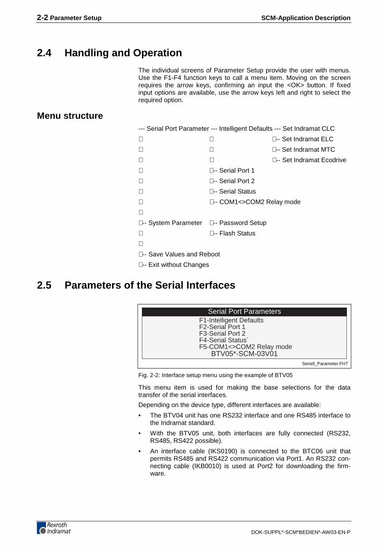
Fig. 2-8: Password definition screen
The Screen Manager features three different password levels, the levels1-3. As shown on the screen (see Fig. 2-6), level 1 is the highest level. Inan application, the passwords can be assigned as follows:
Each programmed screen can be protected by a password. This restrictsthe access to individual screens to specific persons who are authorized tomodify the settings. The three password levels make it possible to grantdifferent display contents access privileges to different users. A user whoknows the password of the first level is able to access all areas, includingthe system settings (interface parameters, display settings, etc.) of therespective unit, even if these areas are protected by a different password.Each lower level permits an increased number of operator inputrestrictions to be defined. Thus, password management is only expedientif level 1 has been assigned.
Note: While a password of a higher level can always be used foraccessing a screen that is protected by a lower passwordlevel, the password of a lower level does not grant access to ahigher level.
All passwords are stored in the Flash of a configuration module. The Dolfidownload program makes this module visible. Here, "Configdata" isdisplayed on the "Header" tab (see Fig. 2-9).

SCM-Application Description Parameter Setup 2-7
DOK-SUPPL*-SCM*BEDIEN*-AW03-EN-P
Configdata.bmp
Fig. 2-9: Dolfi register “Header” displaying the "Configdata" module
In the event, that you have forgotten an entered password and are nolonger able to work with the unit, the Dolfi tool can be used for loading thesoftware configuration that exists in the unit right after the first-time com-missioning. In the event of a password lock, this is the only possibility ofentering a configuration module into the Flash.
Note: The "Configdata" file should be read out once prior to first-timecommissioning.
The process of reading out modules and the general handling of the Dolfitool are described in the next chapter.
Note: Passwords and parameters are not overwritten, neither duringthe software download nor when a new project is downloaded.

2-8 Parameter Setup SCM-Application Description
DOK-SUPPL*-SCM*BEDIEN*-AW03-EN-P
2.8 Flash Status
Flash file directory
Prepare file upload: F1Erase: DEL-file F6-all
30 files / 178888 byte82744 byte availableerase space:0 files / 0 byte(write count 66)
Total Size 5294Name Size 10Dat Size 5234Appl. CRC f2ae0f6cAttribute User
Datei1.xxx_ _ _ _ _ _ _ _ _ _ _ _Datei2.xxx_ _ _ _ _ _ _ _ _ _ _ _Datei3.xyz_ _ _ _ _ _ _ _ _ _ _ _Datei4.xyz_ _ _ _ _ _ _ _ _ _ _ _Datei5.yyy_ _ _ _ _ _ _ _ _ _ _ _Datei6.xxx_ _ _ _ _ _ _ _ _ _ _ _Datei7.yyy_ _ _ _ _ _ _ _ _ _ _ _Datei8.xyz_ _ _ _ _ _ _ _ _ _ _ _Datei9.xxx_ _ _ _ _ _ _ _ _ _ _ _
BA
C DFlash_file_directory.FH7
Fig. 2-10: Flash file directory
The "Flash Status" menu item is represented on a small operator inputunit (here: BTV06) as shown in Fig. 2-10. The contents of the flash, filesizes, checksums of the storing applications, attributes, etc. are specifiedhere. A file can be created in the following ways:
• By the application using adequate programming
• By the ScreenManager Runtime for the temporary storage of controlinformation that otherwise would have to be loaded from the controllerwhenever the unit is switched on (MTC/ISP MiniMap file, ProVi mes-sages, ELC command formats, etc.).
• By the ScreenManager programming desktop (version 4 or later)
Although the File System can be used in many ways, it should mainly beused for the occasional storage of programs, parameters, user settings,texts, and controller states. Due to its physical FLASH storage medium,the system is not suitable for creating regular log files. Regular read andwrite processes would destroy the flash once the number of 50,000 com-pression cycles had been exceeded. Since the compression process isonly initiated after the entire available flash has been written once, this isvery much if storing a file is initiated by pressing a button (e.g. for CLMprogram storage). If, however, a table of 10,000 measured values werewritten automatically every 10 s, the flash would be destroyed after ap-proximately 70 days. Thus, quite a simple, yet efficient precaution is takenin the software (see Chapter 10.8 FLASH Lifetime Warning). If automaticwriting occurs too frequently, the user is forced to acknowledge a window.This prevents an unintentional continuous run of such a killer application.
SCM-Application Description Parameter Setup 2-9
DOK-SUPPL*-SCM*BEDIEN*-AW03-EN-P
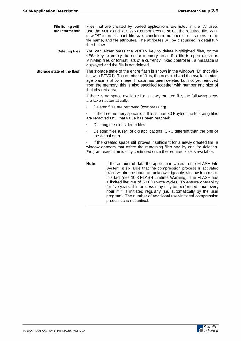
Files that are created by loaded applications are listed in the "A" area.Use the <UP> and <DOWN> cursor keys to select the required file. Win-dow "B" informs about file size, checksum, number of characters in thefile name, and file attributes. The attributes will be discussed in detail fur-ther below.
You can either press the <DEL> key to delete highlighted files, or the<F6> key to empty the entire memory area. If a file is open (such asMiniMap files or format lists of a currently linked controller), a message isdisplayed and the file is not deleted.
The storage state of the entire flash is shown in the windows "D" (not visi-ble with BTV04). The number of files, the occupied and the available stor-age place is shown here. If data has been deleted but not yet removedfrom the memory, this is also specified together with number and size ofthat cleared area.
If there is no space available for a newly created file, the following stepsare taken automatically:
• Deleted files are removed (compressing)
• If the free memory space is still less than 80 Kbytes, the following filesare removed until that value has been reached:
• Deleting the oldest temp files
• Deleting files (user) of old applications (CRC different than the one ofthe actual one)
• If the created space still proves insufficient for a newly created file, awindow appears that offers the remaining files one by one for deletion.Program execution is only continued once the required size is available.
Note: If the amount of data the application writes to the FLASH FileSystem is so large that the compression process is activatedtwice within one hour, an acknowledgeable window informs ofthis fact (see 10.8 FLASH Lifetime Warning). The FLASH hasa limited lifetime of 50.000 write cycles. To ensure operabilityfor five years, this process may only be performed once everyhour if it is initiated regularly (i.e. automatically by the userprogram). The number of additional user-initiated compressionprocesses is not critical.
File listing withfile information
Deleting files
Storage state of the flash
2-10 Parameter Setup SCM-Application Description
DOK-SUPPL*-SCM*BEDIEN*-AW03-EN-P
Pressing <F1> permits the process described above to be initiated manu-ally at any time. This starts the following sequences:
• Deleted files are removed (compressing)
• If the free memory space is still less than 80 Kbytes, the following filesare removed until that value has been reached:
• Deleting the oldest temp files
• Deleting files (user) of old applications (CRC different than the one ofthe actual one)
• Next:
• Writing a header that is valid for Dolfi Upload.
• Calculating the checksum that is valid for the currently existing filesystem.
Note: It is only immediately after this procedure has been performedthat the file system can successfully be saved using Dolfi. Ifthe file system was modified after compression (new files werecreated or existing ones deleted), Dolfi can still be used for anupload, but the data loaded in the PC are useless. Saving thedata in that window immediately after compression is the saf-est possibility of a correct file upload.
Representation on the BTV04 unitThe display size does not allow the complete Flash File Directory to berepresented (as shown above). Merely a list of the created files is shownhere. You must select a line if you wish additional information about thefile. The file information is displayed in a new window.
AttributesAttributes stand for different file types that are created by the loaded ap-plications or by the ScreenManager itself. Distinction is made between:
• "Static"
⇒ is created by the SCMV04 (PC file)
• "User"
⇒ is created by the SCM program
• "Temp"
⇒ cache from ELC formatting
⇒ cache from MTC MiniMap file
Compressing the flash contents

SCM-Application Description Parameter Setup 2-11
DOK-SUPPL*-SCM*BEDIEN*-AW03-EN-P
Reading and loading file systems via DolfiThe download tool Dolfi permits the file that contains information aboutthe flash memory to be made visible on the PC. From here, a file systemcan be backed up or newly be loaded. A "File System" module is listed inthe "Header" window of the download software (see Fig. 2-11).
FileSystem.bmp
Fig. 2-11: Dolfi header window with highlighted "File System" module
Note: The existing old system in the miniature control panel is over-written when a complete file system is uploaded.
To be able to establish a connection between the PC and the small op-erator input unit and to perform a module backup, you must proceed ac-cording to the detailed description in Chapter 3.2 Reading Out Modules.
Attention: A useful file system can only be read after a compression pro-cess (see page 2-10).
Connection setup andupload

2-12 Parameter Setup SCM-Application Description
DOK-SUPPL*-SCM*BEDIEN*-AW03-EN-P

SCM-Application Description Firmware Download Tool Dolfi 3-1
DOK-SUPPL*-SCM*BEDIEN*-AW03-EN-P
3 Firmware Download Tool Dolfi
3.1 The Dolfi User Interface
Erklärung_screen.bmp
Fig. 3-1: Dolfi user interface
Dolfi is a tool that is used for carrying out firmware updates via the serialinterface. Each unit contains several modules that can be replaced indi-vidually. Usually, there are two modules, a base module (Boot loader) anda firmware module. The base module is necessary for replacing the firm-ware module.
After Serial - Firmwareinfo has been executed, Dolfi represents the in-formation about the individual modules in the Header window.
3-2 Firmware Download Tool Dolfi SCM-Application Description
DOK-SUPPL*-SCM*BEDIEN*-AW03-EN-P
3.2 Reading Out Modules
The process of reading out individual modules from the Flash can beused in many ways:
• Copying ("Cloning") device configurations such as interface parame-ters, passwords, etc.
• Circumventing forgotten passwords – the Configdata module must bereplaced.
• Backup for service work.
Giving the BTC06 unit as an example, the process of reading out pa-rameters (including passwords) is explained below.
1) The unit’s RS232 link to the PC must be established.2) Call Dolfi.3) Make the following entries under Settings:
(a) Interface:
• Select the PC interface (COM1-4).
• Select the baud rate for Connect.
• Select the baud rate for Download (recommended: 38400).
(b) Enter the address.
(c) Select the required language (German/English).
4) Press the Connect button.
Use Serial - Scan to search for the unit if you cannot locate it.
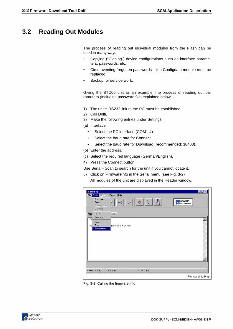
5) Click on Firmwareinfo in the Serial menu (see Fig. 3-2)
All modules of the unit are displayed in the Header window.
Firmwareinfo.bmp
Fig. 3-2: Calling the firmware info
SCM-Application Description Firmware Download Tool Dolfi 3-3
DOK-SUPPL*-SCM*BEDIEN*-AW03-EN-P
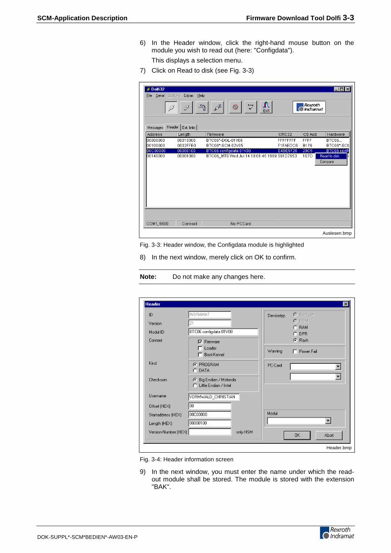
6) In the Header window, click the right-hand mouse button on themodule you wish to read out (here: "Configdata").
This displays a selection menu.
7) Click on Read to disk (see Fig. 3-3)
Auslesen.bmp
Fig. 3-3: Header window, the Configdata module is highlighted
8) In the next window, merely click on OK to confirm.
Note: Do not make any changes here.
Header.bmp
Fig. 3-4: Header information screen
9) In the next window, you must enter the name under which the read-out module shall be stored. The module is stored with the extension"BAK".

3-4 Firmware Download Tool Dolfi SCM-Application Description
DOK-SUPPL*-SCM*BEDIEN*-AW03-EN-P
Note: The module can be reloaded under the same format.
Likewise, parameter settings can be copied from one unit to other oneswithout selecting them in menus.
SCM-Application Description Typical Applications for Indramat Controllers 4-1
DOK-SUPPL*-SCM*BEDIEN*-AW03-EN-P
4 Typical Applications for Indramat ControllersApplications of the individual Indramat controllers (CLC-GPS, ELC, DLC,ISP200, MTC200...) are described in the following chapters.
Note: Albeit Indramat does not assume any responsibility for thesoftware examples, the utilization of the programs is free untilfurther notice.
4.1 Hardware Requirements
To implement the visualization of Indramat controllers with the miniaturecontrol panels, the following components are required:
• The controllers that are used in the individual applications.
• The motor that is supported by the drive controller.
• The operator input unit (miniature control panel) with the correspond-ing ScreenManager Runtime (e. g. SWA-BTV04*-SCM-03-VRS)
• Interface cable for communication setup.
And, in addition for first-time commissioning:
• Off-the-shelf PC
• Download tool Dolfi (is enclosed to BTV Runtime).
• Interface cable PC - miniature control panel
Optional:
• ScreenManager software (SWA-SCM*PC-INB-01-VRSMS-C1.44) tobe able to make individual modifications (customized texts, images,input fields, ...) at the program.

4-2 Typical Applications for Indramat Controllers SCM-Application Description
DOK-SUPPL*-SCM*BEDIEN*-AW03-EN-P
SCM-Application Description BTV04 with DKC03 5-1
DOK-SUPPL*-SCM*BEDIEN*-AW03-EN-P
5 BTV04 with DKC03
5.1 Device settings
An unambiguous bus address must be set at the DKC unit. A bus addressmust not be duplicated if there is more than one device on the bus.
In the default configuration, the BTV is configured with address 0 as thebus master. The typical program is designed for a DKC with the driveaddress 1. Thus, you must set the DKC address to 1.
To do this, rotate the S3 address switch on the DKC to "0" and the S2switch to "1". To initialize the address, switch the DKC unit off and backon.
Note: Your DKC may be set to software address selection. See DKCparameter P-0-4022. In addition, the default setting of Serial-Port2 (PC interface) is 3, so that it may not be used for a DKCaddress.
If the value of "256" has been entered in the communication parameter P-0-4022, the device address that is set at the address switch is used forserial communication (not "256").
Setting the baud rateThe baud rates of DKC and BTV must agree (default: baud rate 9600).
See DKC parameter P-0-04021.
0 = 9600
1= 19200
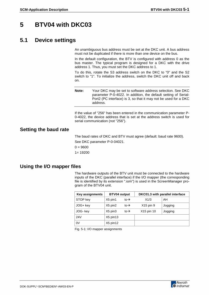
Using the I/O mapper filesThe hardware outputs of the BTV unit must be connected to the hardwareinputs of the DKC (parallel interface) if the I/O mapper (the correspondingfile is identified by its extension ".iom") is used in the ScreenManager pro-gram of the BTV04 unit.
Key assignments BTV04 output DKC01.3 with parallel interface
STOP key X5 pin1 toÅ X1/3 AH
JOG+ key X5 pin2 toÅ X15 pin 9 Jogging
JOG- key X5 pin3 toÅ X15 pin 10 Jogging
24V X5 pin13
0V X5 pin12
Fig. 5-1: I/O mapper assignments

5-2 BTV04 with DKC03 SCM-Application Description
DOK-SUPPL*-SCM*BEDIEN*-AW03-EN-P
Mode-specific settingsDepending on the selected mode there may still be parameter settingsrequired in the DKC.
The position block selection is always made via the hardware inputs. If theselection is to be made via the serial interface, modifications must bemade to the signal control word S-0-0145. This requires the "Configura-tion list signal control word" S-0-0027 to be changed as follows:
With Drivetop
• Use "Parameter" Å "special/optional drive functions" to select the"Signal control word" list.
• Assign different values to bit 0 – 5 (e.g. jogging).
With BTV04
• Use "Parameter" Å "Single parameter" to select the S-0-0027 pa-rameter. Overwrite element 0 – 5 of the parameter list with the valueP-0-4056.
Check the selected limit values of the DKC if a programmed positionblock does not achieve the expected velocities, accelerations, etc., or ifthe DKC unit breaks down with an E*** error. The limit values can easilybe interrogated and modified via "Parameter" Å "Limit values" in theBTV04 unit.
Use the following procedure to activate the mode in conjunction withanalog control communications:
• Select the mode
• Set the parameter value of the analog channel P-0-0213, Analoginput 1, assignment to the parameter S-0-0036 , velocity com-mand value
• Define the required resolution with the help of P-0-0214, Analog in-put 1, evaluation per 10V.
• If necessary, offset compensation via P-0-0217, Analog input 1, off-set.
Use the following procedure to activate the mode in conjunction withanalog control communications:
• Select the mode
• Set the parameter value of the analog channel P-0-0213, Analoginput 1, assignment to the parameter S-0-0080 , torque/forcecommand value
• Define the required resolution with the help of P-0-0214, Analog in-put 1, evaluation per 10V.
• If necessary, offset compensation via P-0-0217, Analog input 1, off-set.
Positioning interface
Velocity control
Torque control

SCM-Application Description BTV04 with DKC03 5-3
DOK-SUPPL*-SCM*BEDIEN*-AW03-EN-P
5.2 Program Description
Overview of BTV keysCertain keys on the BTV unit has always the same function with this ap-plication.
Keys Function in the program
Alphanumeric entry for editing parameters and vari-ables of any kind. Pressing the [Shift] key at thesame time activates the letters with a green back-ground. Pressing the key repeatedly shows the let-ters in succession. Release the [Shift] key to acceptthe letter last pressed.
Selecting or scrolling through input fields and menuitems.
Menu selection or program structuring.
Shift key. Permits multiple key assignments (e.g.[SHIFT] + [7] = A) to be made.
Is only active in positioning block mode. Is used forstarting position blocks via RS485.
Changeover to a function-reduced selection menu.
Switches the Q1 output on the BTV unit (to activatethe DriveHalt signal, for example).
Jogging. Prerequisite: See Chapter "Using the I/Omapper files".
Clear error
Activates a diagnosis screen that informs about thedrive state.
Return to the previous screen or abortion of inputs.
Jumps to the program main menu.
Acknowledgement of entries and menu selections.
Fig. 5-2: Key assignments

5-4 BTV04 with DKC03 SCM-Application Description
DOK-SUPPL*-SCM*BEDIEN*-AW03-EN-P
Handling the BTV unitThe BTV menus are always selected via function keys or the arrow keys.When the arrow keys are used for selection, the currently active line ishighlighted and can be selected by pressing the OK key. When functionkeys are used for menu control, the required menu can be selected bymerely pressing the corresponding function key.
Edit fields (i.e. fields that permit an input via the keyboard to be imple-mented using the BTV unit) are also selected via the arrow keys. Theentry must be acknowledged by pressing the OK button as soon as it iscompleted. Making all the entries in several edit fields first, and pressingthe OK key for acknowledgment at the end of the entries is possible.
The MAINMENU key always takes you back to the main menu. The ESCkey takes you back by one window only.
As far as possible, active keys are marked by an illuminated LED.
This example also mentions briefly the I/O mapper. The program firmlyinterconnects the following keys with the I/O mapper:
Key on the BTV04unit
Output on the BTV04unit
Function in the application
STOP Q1 Switch AH
JOG+ Q2 Jog forward
JOG- Q3 Jog backward
Fig. 5-3: Key assignments (invariable)
To use the keys, 24V must be applied to the outputs, and the corre-sponding inputs of the DKC must be interconnected with the BTV outputs(see Chapter "Using the I/O mapper files").
SCM-Application Description BTV04 with DKC03 5-5
DOK-SUPPL*-SCM*BEDIEN*-AW03-EN-P
5.3 Menu
Main menu
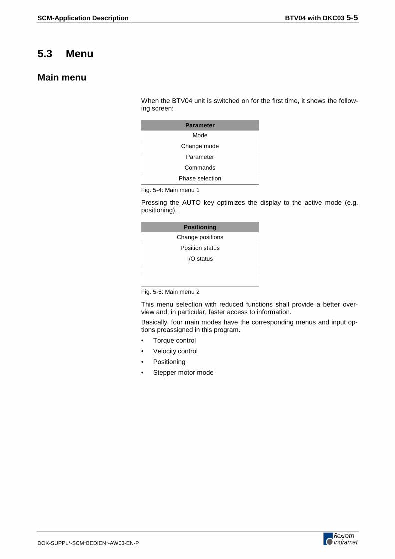
When the BTV04 unit is switched on for the first time, it shows the follow-ing screen:
Parameter
Mode
Change mode
Parameter
Commands
Phase selection
Fig. 5-4: Main menu 1
Pressing the AUTO key optimizes the display to the active mode (e.g.positioning).
Positioning
Change positions
Position status
I/O status
Fig. 5-5: Main menu 2
This menu selection with reduced functions shall provide a better over-view and, in particular, faster access to information.
Basically, four main modes have the corresponding menus and input op-tions preassigned in this program.
• Torque control
• Velocity control
• Positioning
• Stepper motor mode

5-6 BTV04 with DKC03 SCM-Application Description
DOK-SUPPL*-SCM*BEDIEN*-AW03-EN-P
Mode
Torque control
Torque control
Editing parameters
Status
Fig. 5-6: Torque control main menu
Selecting the "Editing parameters" menu item displays the effective peakcurrent (P-0-4046) and permits the two parameters "Torque/force com-mand value (S-0-0080)" and "Torque/force command value filter timeconstant (P-0-0176)" to be edited.
Abbreviations:
• Tq/F = Torque/force command value
• Tq/F GZK = Torque/force command value filter time constant
Torque control
Ispitze: 22.999
Tq/F: 0.0
Tq/F GZK: 0
Fig. 5-7: Torque control / parameter
A selection of the I/O assignments of the BTV and DKC units appears viathe selection of the individual submenus.
See also "Status" section.
Velocity control
Velocity control
Editing parameters
Status
Fig. 5-8: Velocity control / main menu
Editing parameters
Status

SCM-Application Description BTV04 with DKC03 5-7
DOK-SUPPL*-SCM*BEDIEN*-AW03-EN-P
Selecting the "Editing parameters" menu item displays the "Active peakcurrent" (P-0-4046) and "Velocity feedback value" (S-0-0040) parametersand permits the two parameters "Torque/force command value (S-0-0080)" and "Torque/force command value filter time constant (P-0-0176)"to be edited.
Abbreviations:
• Tq/F = Torque/force command value
• Tq/F GZK = Torque/force command value filter time constant
Torque control
Ispitze: 22.999
Tq/F: 0.0
Tq/F GZK: 0
Vist 2999.026
Fig. 5-9: Velocity control / parameter
See also "Status" section.
Positioning mode
Positioning
Change positions
Position status
I/O status
Fig. 5-10: Positioning main menu
Change positions
There are input fields behind the "Change positions" menu item that canbe used for making the major position inputs:
• Select position block
• Enter target position
• Enter velocity
• Enter acceleration
• Enter jerk
• Optionally, the position mode can be selected via the F1 key; the po-sition can be entered in "teach-in mode" via the F2 key.
Important: First, enter the corresponding block number to select theprocess block, and acknowledge immediately by pressingOK in order to load the current values from the DKC.
Editing parameters
Status

5-8 BTV04 with DKC03 SCM-Application Description
DOK-SUPPL*-SCM*BEDIEN*-AW03-EN-P
Position block 4
Pos.: 1500.0000
Velocity: 1000.0000
Acceleration: 500.000
Jerk 0.000
F1=PosMode F2=Teach-in
Fig. 5-11: Editing position data
Use the arrow keys to jump to the individual input fields. Enter a figure orpress the right arrow key to activate the selected input field (shown by ablinking cursor).
Position block mode
Position block 4
Next block at target position
Without stop (mode1)
Relative
Fig. 5-12: Position block mode
Use the arrow keys to select the position mode, and confirm the selectionwith the OK key.
Position block
Active pos. block 4
POSziel: 1500.0000
POSakt.: 3360.0000
Acceptance with [OK]
Fig. 5-13: Teach-in
When the controller enabling signal is set, the JOG keys can be used formoving the motor in both directions. When the required position value isreached, pressing the OK key accepts the value into the selected positionblock.
Position status
Active NC block 4
[START]=Start NC block
POSziel: 1500.0000
POSakt.: 3360.0000
Vist 999.8710
Tqist 35.2
Fig. 5-14: Position status
F1=PosMode
F2=Teach-in
SCM-Application Description BTV04 with DKC03 5-9
DOK-SUPPL*-SCM*BEDIEN*-AW03-EN-P
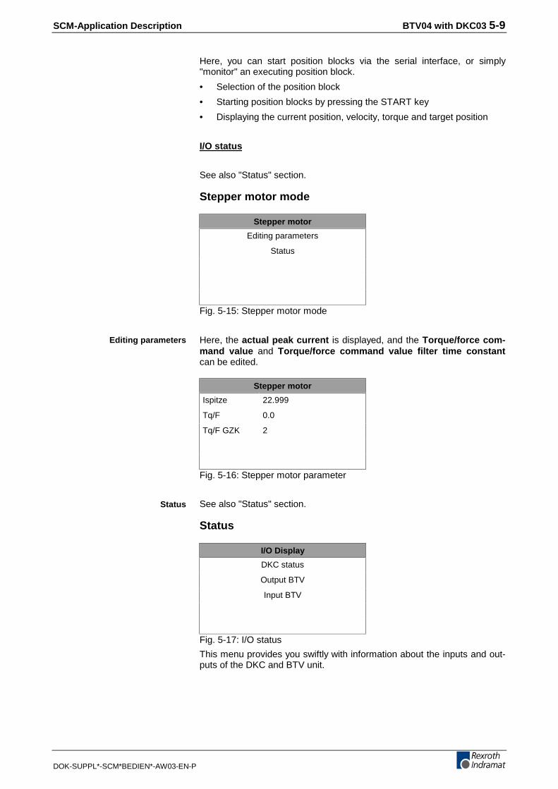
Here, you can start position blocks via the serial interface, or simply"monitor" an executing position block.
• Selection of the position block
• Starting position blocks by pressing the START key
• Displaying the current position, velocity, torque and target position
I/O status
See also "Status" section.
Stepper motor mode
Stepper motor
Editing parameters
Status
Fig. 5-15: Stepper motor mode
Here, the actual peak current is displayed, and the Torque/force com-mand value and Torque/force command value filter time constantcan be edited.
Stepper motor
Ispitze 22.999
Tq/F 0.0
Tq/F GZK 2
Fig. 5-16: Stepper motor parameter
See also "Status" section.
Status
I/O Display
DKC status
Output BTV
Input BTV
Fig. 5-17: I/O status
This menu provides you swiftly with information about the inputs and out-puts of the DKC and BTV unit.
Editing parameters
Status

5-10 BTV04 with DKC03 SCM-Application Description
DOK-SUPPL*-SCM*BEDIEN*-AW03-EN-P
Display of status messages (such as cams, emergency stop, etc.).
Use the F1 key to scroll to the next display.
DKC status
FBG+ Estop
FBG- Jog+
Cam1 Jog-
Cam2 Still
F1=Others
Fig. 5-18: DKC status
The BTV outputs are shown on the display.
The BTV inputs are shown on the display.
Change mode
Main mode
Torque control
Velocity control
Positioning block mode
Stepper motor mode
Fig. 5-19: Change mode
Use this menu to select the required mode.
Note: The DKC must be in P2 mode. The following message ap-pears if the DKC is not in P2 mode:
To change modes, you must go to
parameter value assignment mode.
F1=Go ESC=Back
Fig. 5-20: Mode message
Press F1 to acknowledge this message if you wish to change modes.
Depending on the mode, you can make additional specifications aboutsensors and lag error. Once the mode has been changed, the DKC be-comes operational again.
DKC status
Output BTV
Input BTV
SCM-Application Description BTV04 with DKC03 5-11
DOK-SUPPL*-SCM*BEDIEN*-AW03-EN-P
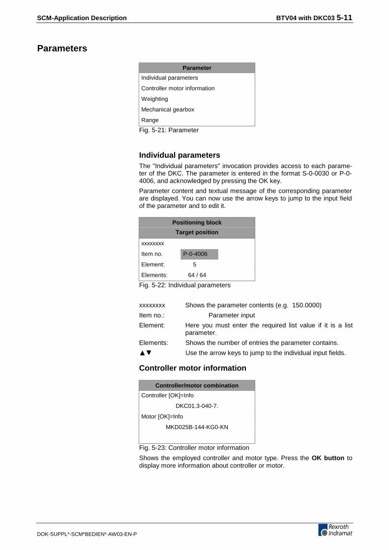
Parameters
Parameter
Individual parameters
Controller motor information
Weighting
Mechanical gearbox
Range
Fig. 5-21: Parameter
Individual parametersThe "Individual parameters" invocation provides access to each parame-ter of the DKC. The parameter is entered in the format S-0-0030 or P-0-4006, and acknowledged by pressing the OK key.
Parameter content and textual message of the corresponding parameterare displayed. You can now use the arrow keys to jump to the input fieldof the parameter and to edit it.
Positioning block
Target position
xxxxxxxx
Item no. P-0-4006
Element: 5
Elements: 64 / 64
Fig. 5-22: Individual parameters
xxxxxxxx Shows the parameter contents (e.g. 150.0000)
Item no.: Parameter input
Element: Here you must enter the required list value if it is a listparameter.
Elements: Shows the number of entries the parameter contains.
Use the arrow keys to jump to the individual input fields.
Controller motor information
Controller/motor combination
Controller [OK]=Info
DKC01.3-040-7.
Motor [OK]=Info
MKD025B-144-KG0-KN
Fig. 5-23: Controller motor information
Shows the employed controller and motor type. Press the OK button todisplay more information about controller or motor.
5-12 BTV04 with DKC03 SCM-Application Description
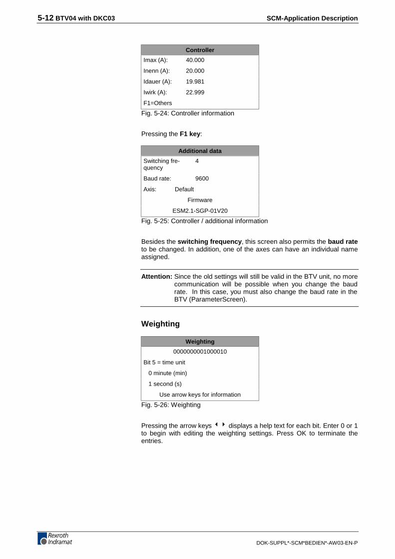
DOK-SUPPL*-SCM*BEDIEN*-AW03-EN-P
Controller
Imax (A): 40.000
Inenn (A): 20.000
Idauer (A): 19.981
Iwirk (A): 22.999
F1=Others
Fig. 5-24: Controller information
Pressing the F1 key:
Additional data
Switching fre-quency
4
Baud rate: 9600
Axis: Default
Firmware
ESM2.1-SGP-01V20
Fig. 5-25: Controller / additional information
Besides the switching frequency, this screen also permits the baud rateto be changed. In addition, one of the axes can have an individual nameassigned.
Attention: Since the old settings will still be valid in the BTV unit, no morecommunication will be possible when you change the baudrate. In this case, you must also change the baud rate in theBTV (ParameterScreen).
Weighting
Weighting
0000000001000010
Bit 5 = time unit
0 minute (min)
1 second (s)
Use arrow keys for information
Fig. 5-26: Weighting
Pressing the arrow keys 34 displays a help text for each bit. Enter 0 or 1to begin with editing the weighting settings. Press OK to terminate theentries.
SCM-Application Description BTV04 with DKC03 5-13
DOK-SUPPL*-SCM*BEDIEN*-AW03-EN-P
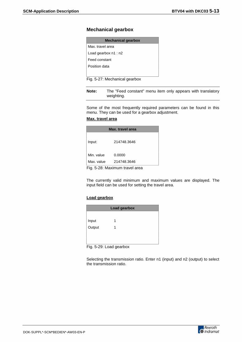
Mechanical gearbox
Mechanical gearbox
Max. travel area
Load gearbox n1 : n2
Feed constant
Position data
Fig. 5-27: Mechanical gearbox
Note: The "Feed constant" menu item only appears with translatoryweighting.
Some of the most frequently required parameters can be found in thismenu. They can be used for a gearbox adjustment.
Max. travel area
Max. travel area
Input: 214748.3646
Min. value 0.0000
Max. value 214748.3646
Fig. 5-28: Maximum travel area
The currently valid minimum and maximum values are displayed. Theinput field can be used for setting the travel area.
Load gearbox
Load gearbox
Input 1
Output 1
Fig. 5-29: Load gearbox
Selecting the transmission ratio. Enter n1 (input) and n2 (output) to selectthe transmission ratio.
5-14 BTV04 with DKC03 SCM-Application Description
DOK-SUPPL*-SCM*BEDIEN*-AW03-EN-P
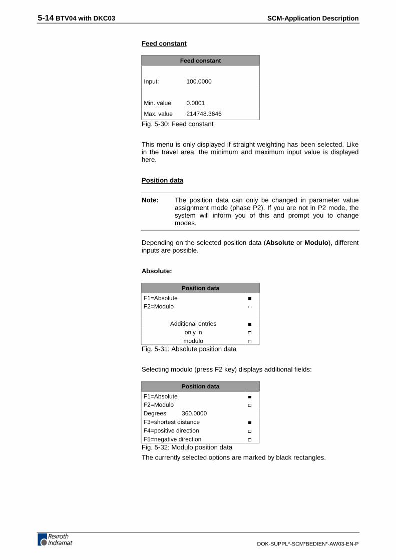
Feed constant
Feed constant
Input: 100.0000
Min. value 0.0001
Max. value 214748.3646
Fig. 5-30: Feed constant
This menu is only displayed if straight weighting has been selected. Likein the travel area, the minimum and maximum input value is displayedhere.
Position data
Note: The position data can only be changed in parameter valueassignment mode (phase P2). If you are not in P2 mode, thesystem will inform you of this and prompt you to changemodes.
Depending on the selected position data (Absolute or Modulo), differentinputs are possible.
Absolute:
Position data
F1=AbsoluteF2=Modulo
Additional entriesonly inmodulo
Fig. 5-31: Absolute position data
Selecting modulo (press F2 key) displays additional fields:
Position data
F1=AbsoluteF2=ModuloDegrees 360.0000F3=shortest distanceF4=positive directionF5=negative direction
Fig. 5-32: Modulo position data
The currently selected options are marked by black rectangles.
SCM-Application Description BTV04 with DKC03 5-15
DOK-SUPPL*-SCM*BEDIEN*-AW03-EN-P
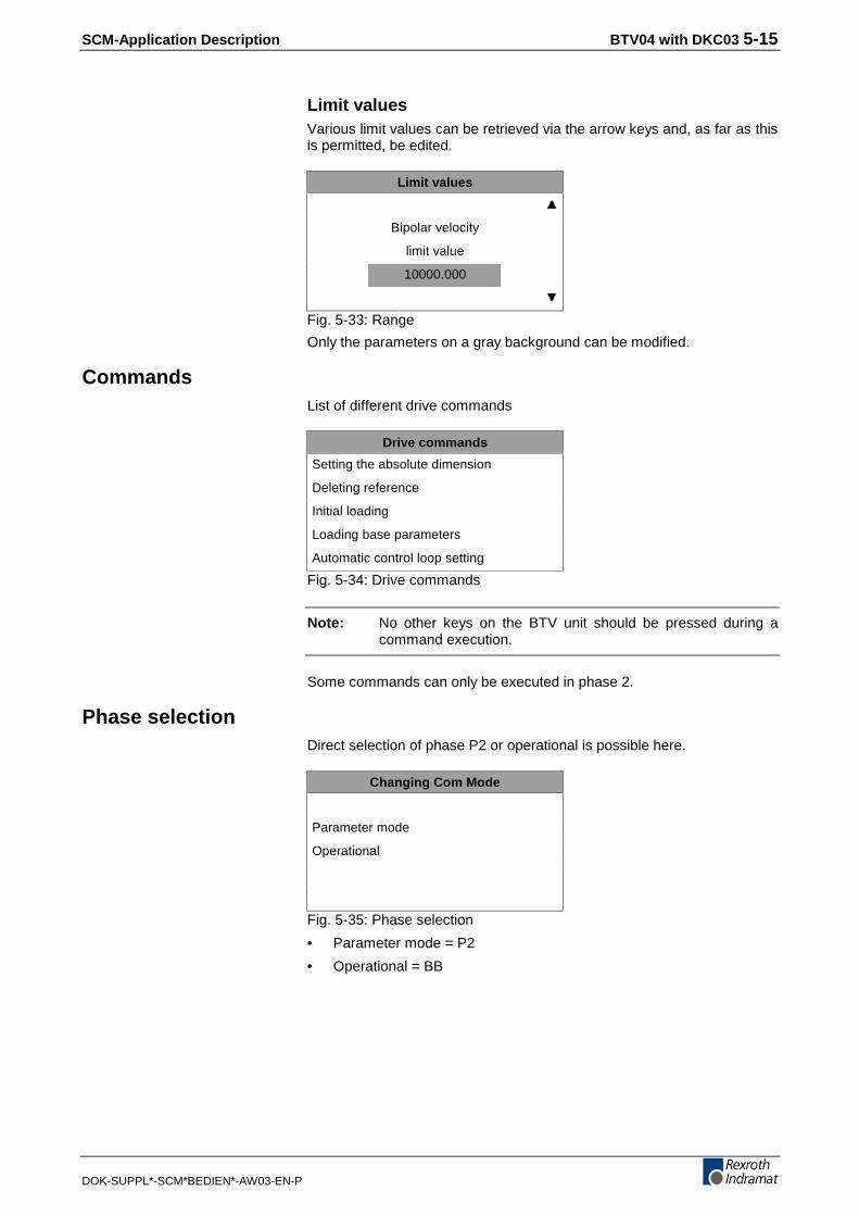
Limit valuesVarious limit values can be retrieved via the arrow keys and, as far as thisis permitted, be edited.
Limit values
Bipolar velocity
limit value
10000.000
Fig. 5-33: Range
Only the parameters on a gray background can be modified.
CommandsList of different drive commands
Drive commands
Setting the absolute dimension
Deleting reference
Initial loading
Loading base parameters
Automatic control loop setting
Fig. 5-34: Drive commands
Note: No other keys on the BTV unit should be pressed during acommand execution.
Some commands can only be executed in phase 2.
Phase selectionDirect selection of phase P2 or operational is possible here.
Changing Com Mode
Parameter mode
Operational
Fig. 5-35: Phase selection
• Parameter mode = P2
• Operational = BB

5-16 BTV04 with DKC03 SCM-Application Description
DOK-SUPPL*-SCM*BEDIEN*-AW03-EN-P

SCM-Application Description BTV04 Unit with Ecodrive03 FLP 6-1
DOK-SUPPL*-SCM*BEDIEN*-AW03-EN-P
6 BTV04 Unit with Ecodrive03 FLP
6.1 Introduction
Purpose of the program
The BTV-ELC program is used for programming and visualizing an Eco-drive03 unit with an integrated FLP NC controller in conjunction with aBTV04 unit.
The program fulfills the following tasks:
• Displaying and editing program blocks of the NC task
• Displaying and editing parameters
• Displaying and editing variables
• Displaying and editing program blocks of the logic task
• Displaying parts counters
• Displaying positions and position lags
• Displaying I/O and flag states
• Displaying diagnosis and fault messages
• Displaying active NC task blocks
•
Additional functionalitiesThere are additional functionalities that may be used:
• Programming and visualizing seven additional Ecodrive03 units
• Using the system keys
• Using the inputs and outputs of the BTV04 unit
• Pass-through operation (communication with the Ecodrive03 units viathe RS232 X3 interface)

6-2 BTV04 Unit with Ecodrive03 FLP SCM-Application Description
DOK-SUPPL*-SCM*BEDIEN*-AW03-EN-P
6.2 Device Settings
ExplanationThe ex-factory delivery of the BTV04 units can be:
• with bootloader and ScreenManager Runtime
• Programming and visualization for FLP (ELC) FWA-BTV04-ELC-01VRS
• Roller feed desktop FWA-BTV04-ELW-01VRS
The bootloader "organizes" the download of the Dolfi program and theprograms that were created using the ScreenManager.
The two other programs are products. Prior to delivery, they are loadedonto the BTV04 unit according to the order.
Communication initializationUpon delivery from the factory, the parameters of Ecodrive03 FLP andBTV04 are adjusted such that they match. The address is preset to 05.
The BTV04 unit should display the main menu once the two units havebeen connected to the power supply and the IKB 0017 connecting cablehas been connected to the X2 connector of both units.
If the "CLM is not responding" error message is displayed, try to clear theerror by pressing the ESC key repeatedly. A menu is displayed that showsthe invariably set address 05. The DKC address selection switches mustbe set to this address. If the error persists after you have pressed the OKkey, you must check the power supply of the Ecodrive03 DKC, and thecable.
In addition, the BTV04 and FLP parameters can be checked in the fol-lowing steps:
Basic settings on the BTV04 unitTo get to the BTV04 parameter menu, use the following procedure:
1. Simultaneously press the [Shift]+[ESC] key combination
2. Next, keep the F2 key on the BTV04 unit depressed
To be able to communicate with the FLP you must make the followingselections:
1. Press the F1 key "Serial Port Parameter"
2. Press the F1 key "Intelligent Defaults"
3. Press the F1 key "Set Indramat ELC".
4. Press the ESC key three times
5. Press the F3 key "Save Values and Reboot".
This parameter setup can also be used for making manual selections atthe ports.
SCM-Application Description BTV04 Unit with Ecodrive03 FLP 6-3
DOK-SUPPL*-SCM*BEDIEN*-AW03-EN-P
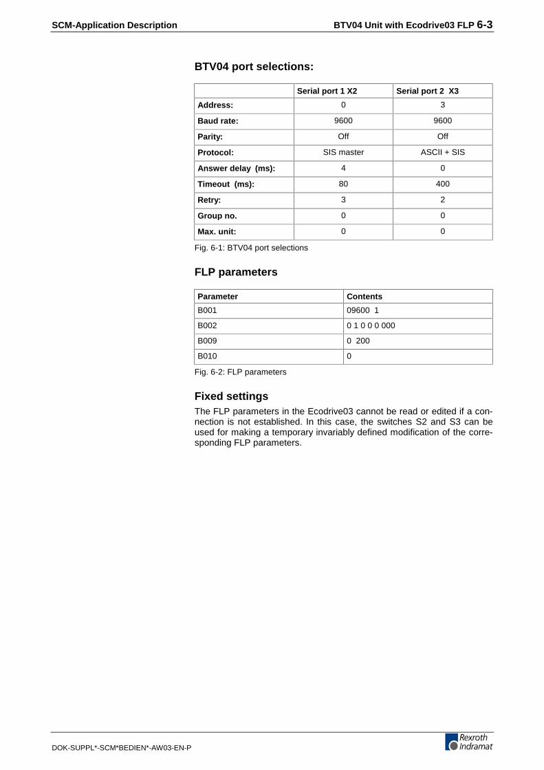
BTV04 port selections:
Serial port 1 X2 Serial port 2 X3
Address: 0 3
Baud rate: 9600 9600
Parity: Off Off
Protocol: SIS master ASCII + SIS
Answer delay (ms): 4 0
Timeout (ms): 80 400
Retry: 3 2
Group no. 0 0
Max. unit: 0 0
Fig. 6-1: BTV04 port selections
FLP parameters
Parameter Contents
B001 09600 1
B002 0 1 0 0 0 000
B009 0 200
B010 0
Fig. 6-2: FLP parameters
Fixed settingsThe FLP parameters in the Ecodrive03 cannot be read or edited if a con-nection is not established. In this case, the switches S2 and S3 can beused for making a temporary invariably defined modification of the corre-sponding FLP parameters.
6-4 BTV04 Unit with Ecodrive03 FLP SCM-Application Description
DOK-SUPPL*-SCM*BEDIEN*-AW03-EN-P
Switch S3 Switch S2
Adjusteddrive address
Fp5032f1.FH7
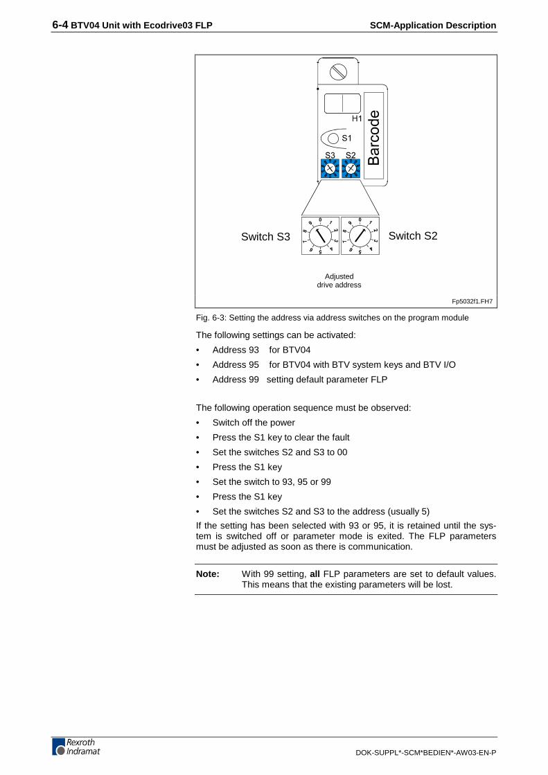
Fig. 6-3: Setting the address via address switches on the program module
The following settings can be activated:
• Address 93 for BTV04
• Address 95 for BTV04 with BTV system keys and BTV I/O
• Address 99 setting default parameter FLP
The following operation sequence must be observed:
• Switch off the power
• Press the S1 key to clear the fault
• Set the switches S2 and S3 to 00
• Press the S1 key
• Set the switch to 93, 95 or 99
• Press the S1 key
• Set the switches S2 and S3 to the address (usually 5)
If the setting has been selected with 93 or 95, it is retained until the sys-tem is switched off or parameter mode is exited. The FLP parametersmust be adjusted as soon as there is communication.
Note: With 99 setting, all FLP parameters are set to default values.This means that the existing parameters will be lost.

SCM-Application Description BTV04 Unit with Ecodrive03 FLP 6-5
DOK-SUPPL*-SCM*BEDIEN*-AW03-EN-P
6.3 Program Description
Navigation and handlingSelection of submenus or input fields via function keys.
Numeric values or alphabetical characters are entered via the alphanu-meric keyboard. Pressing the Shift key at the same time activates the(alphabetical) keys on a green background.
Menu and function selection. Keys are always explainedby a text on the display.
Used for entering and editing numbers and text. Pressingthe [Shift] key at the same time activates the letters on agreen background.
Shift key is activated when a double-assigned key (dualcolor keys) is pressed at the same time.
To save an input or a selected menu item.
Goes back by one screen, or aborts an entry.
Used for navigating within the user interface.
ParameterThe previous parameter block is invoked if the cursor sitson the parameter block identification.
NC programmingThe commands can be scrolled if the cursor sits on thecommand. If the cursor sits on a location that may containQ,M,I, these letters will be scrolled.
In any other case, the cursor jumps to a different line.
These keys can be activated with the parameters B009and B010 (the system inputs via the Profibus inputs willthen be inactive).
Pressing these keys increments or decrements by 1 theblock number or parameter number in the programmingwindows.
Shows an incorrect parameter (if there is one).
Directly to the main menu
Fig. 6-4: Key assignments

6-6 BTV04 Unit with Ecodrive03 FLP SCM-Application Description
DOK-SUPPL*-SCM*BEDIEN*-AW03-EN-P
Menu
Overview
Fig. 6-5: Menu overview
Display menu
Address menu
Fig. 6-6: Address menu
When the power is switched on, the BTV04 first displays an Englishdesktop. If they are not yet available, display rules and linguistically differ-ent texts will be read from the DKC21.3 or DKC3.3.
Next, the system branches to the main menu.
If you press the ESC key to change back to the start display, this one willnow be displayed in the preselected language.
B T V 0 4 E L C x x V x x
E L C – A D D R E S S
5
M A I N – M E N U ( O K )
OK Main menu F1 Machine menu F1 Position
F2 I/O menu F1 inputs
F2 outputs
F3 counters
F2 input menu F1 NC program
F2 parameter
F3 PLC program (logic task)
F4 variable
F3 diagnosis F1 I/O/F menu F1 inputs
F2 outputs
F3 flags
F2 program status
F3 miscell. F1 position lag
F4 variables

SCM-Application Description BTV04 Unit with Ecodrive03 FLP 6-7
DOK-SUPPL*-SCM*BEDIEN*-AW03-EN-P
Start display in English
Fig. 6-7: Start display
The software number of the BTV04 unit is displayed in the status display.
The ELC address must agree with the address selected on the DKC pro-gramming module.
Main menu
Status line
or DKC3.3
or ECODR3-FLP
Fig. 6-8: Main menu
Machine menu
Status line
Selected menu
Fig. 6-9: Machine menu
B T V 0 4 E L C x x V x x
E L C – A D D R E S S
1
M A I N M E N U ( O K )
S e t u p
M A I N M E N U
D K C 2 1 . 3
E C O D R 3 – F L P – x x V x x
M A C H I N E M E N U ( F 1 )
I N P U T M E N U ( F 2 )
D I A G N O S I S M E N U ( F 3 )
S e t u p
M A C H I N E M E N U
P O S I T I O N ( F 1 )
I / O – M E N U ( F 2 )
C O U N T E R ( F 3 )

6-8 BTV04 Unit with Ecodrive03 FLP SCM-Application Description
DOK-SUPPL*-SCM*BEDIEN*-AW03-EN-P
Axis position
Fig. 6-10: Position menu
Fig. 6-11: I/O menu
Ascending bit
sequence from
right to left
Fig. 6-12: Input setup
Fig. 6-13: Output setup
Position
I/O menu
S e t u p
S P E E D :
+ 0 0 0 0 . 0 9
A B S O L U T E P O S I T I O N
+ 0 8 4 2 2 5 . 0 9 0
D E L E T E P O S . ( 0 )
S e t u p
I / O M E N U
I N P U T S ( F 1 )
O U T P U T S ( F 2 )
S e t u p
I N P U T S
I 0 . 0 0 0 0 0 0 0 0 0 0
I 0 . 0 1 0 0 0 0 0 0 0 0
I 1 . 0 0 0 0 0 0 0 0 0 0
I 1 . 0 1 0 0 0 0 0 0 0 0
I 1 . 0 2 0 0 0 0 0 0 0 0
S e t u p
O U T P U T S
Q 0 . 0 0 0 0 0 0 0 1 0 1
Q 0 . 0 1 0 0 0 0 0 0 0 0
Q 1 . 0 0 0 0 0 0 0 0 0 0
Q 1 . 0 1 0 0 0 0 0 0 0 0
Q 1 . 0 2 0 0 0 0 0 0 0 0
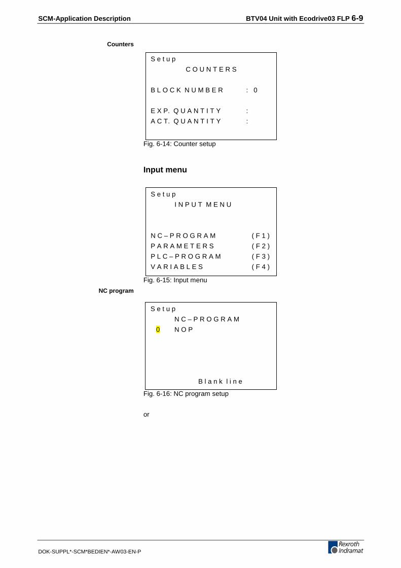
SCM-Application Description BTV04 Unit with Ecodrive03 FLP 6-9
DOK-SUPPL*-SCM*BEDIEN*-AW03-EN-P
Fig. 6-14: Counter setup
Input menu
Fig. 6-15: Input menu
Fig. 6-16: NC program setup
or
Counters
NC program
S e t u p
I N P U T M E N U
N C – P R O G R A M ( F 1 )
P A R A M E T E R S ( F 2 )
P L C – P R O G R A M ( F 3 )
V A R I A B L E S ( F 4 )
S e t u p
C O U N T E R S
B L O C K N U M B E R : 0
E X P. Q U A N T I T Y :
A C T. Q U A N T I T Y :
S e t u p
N C – P R O G R A M
0 N O P
B l a n k l i n e

6-10 BTV04 Unit with Ecodrive03 FLP SCM-Application Description
DOK-SUPPL*-SCM*BEDIEN*-AW03-EN-P
Fig. 6-17: NC program setup
If the cursor sits on
• the command, the "arrow up" and "arrow down" keys can be used forscrolling the command list. Furthermore, the command function de-scription is displayed on the last two lines.
• the first location of the input fields, the "arrow up" and "arrow down"keys can be used for selecting M'=flag, ‚I'=input, ‚Q'=output or ‚0'=nomeaning (depending on the meaning of the command input field).Furthermore, the function description of this input field is displayed onthe last two lines.
H = Help key possible
Fig. 6-18: Motion type parameter setup
Fig. 6-19: Parameter function sensor 2 setup
Parameters
S e t u p
N C – P R O G R A M
9 9 9 P S A
1 + 0 0 0 5 0 0 . 0 0 0
9 9 9
F e e d a b s o l u t e w i t h
p o s i t i o n a c k n o w l e d g.
S e t u p
P A R A M E T E R ‚ H ‚
A 1 0 0
0 0
M o t i o n t y p e
S e t u p
P A R A M E T E R ‚ H ‚
A 1 0 1
0 1
F u n c t i o n S e n s o r 2

SCM-Application Description BTV04 Unit with Ecodrive03 FLP 6-11
DOK-SUPPL*-SCM*BEDIEN*-AW03-EN-P
If the cursor sits on
• the parameter block (A1,AA,B0;C0,CR,CM,CA), the "arrow up" and"arrow down" keys can be used for scrolling.
• the parameter number, the "Page up" and "Page down" keys can beused for direct incrementing or decrementing input. Furthermore, theparameter function description is displayed on the last two lines.
• the first location of the input fields, the "arrow up" and "arrow down"keys can be used for selecting M'=flag, ‚I'=input, ‚Q'=output or ‚0'=nomeaning (depending on the meaning of the command input field).Furthermore, the function description of this input field is displayed onthe last two lines.
Fig. 6-20: PLC program setup
In the highlighted lines, the command can be edited directly using thealphanumeric keys. The block number can be edited via the arrow keys orby direct input.
Fig. 6-21: Variable setup
Variables can be edited here.
PLC program
Variables
S e t u p
P L C – P R O G R A M
0 0 0 0 E N D
> 0 0 0 1 N O P
0 0 0 2 N O P
S e t u p
V A R I A B L E S
V 6 0 0 + 0 0 0 0 0 0 0 0 . 0 0 0 0 0 0
V 6 0 0 . . . V 9 9 9

6-12 BTV04 Unit with Ecodrive03 FLP SCM-Application Description
DOK-SUPPL*-SCM*BEDIEN*-AW03-EN-P
Diagnosis
Fig. 6-22: Diagnosis setup
Fig. 6-23: I/O/M menu setup
Fig. 6-24: Input setup
Ascending bit sequence from right to left
Fig. 6-25: Output setup
Ascending bit sequence from right to left
I / O / M - Menu
S e t u p
D I A G N O S I S M E N U
I / O / M– M E N U ( F 1 )
P R O G R A M S T A T U S ( F 2 )
M I S C E L L A N E O U S ( F 3 )
V A R I A B L E S ( F 4 )
S e t u p
I / O / M M E N U
I N P U T S ( F 1 )
O U T P U T S ( F 2 )
F L A G S ( F 3 )
S e t u p
I N P U T S
I 0 . 0 0 0 0 0 0 0 0 0 0
I 0 . 0 1 0 0 0 0 0 0 0 0
I 1 . 0 0 0 0 0 0 0 0 0 0
I 1 . 0 1 0 0 0 0 0 0 0 0
I 1 . 0 2 0 0 0 0 0 0 0 0
S e t u p
O U T P U T S
Q 0 . 0 0 0 0 0 0 0 1 0 1
Q 0 . 0 1 0 0 0 0 0 0 0 0
Q 1 . 0 0 0 0 0 0 0 0 0 0
Q 1 . 0 1 0 0 0 0 0 0 0 0
Q 1 . 0 2 0 0 0 0 0 0 0 0
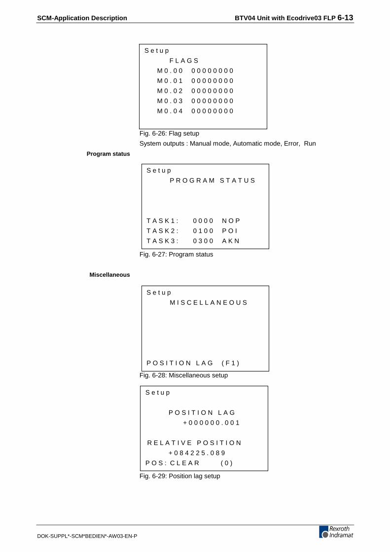
SCM-Application Description BTV04 Unit with Ecodrive03 FLP 6-13
DOK-SUPPL*-SCM*BEDIEN*-AW03-EN-P
Fig. 6-26: Flag setup
System outputs : Manual mode, Automatic mode, Error, Run
Fig. 6-27: Program status
Fig. 6-28: Miscellaneous setup
Fig. 6-29: Position lag setup
Program status
Miscellaneous
S e t u p
P R O G R A M S T A T U S
T A S K 1 : 0 0 0 0 N O P
T A S K 2 : 0 1 0 0 P O I
T A S K 3 : 0 3 0 0 A K N
S e t u p
M I S C E L L A N E O U S
P O S I T I O N L A G ( F 1 )
S e t u p
P O S I T I O N L A G
+ 0 0 0 0 0 0 . 0 0 1
R E L A T I V E P O S I T I O N
+ 0 8 4 2 2 5 . 0 8 9
P O S : C L E A R ( 0 )
S e t u p
F L A G S
M 0 . 0 0 0 0 0 0 0 0 0 0
M 0 . 0 1 0 0 0 0 0 0 0 0
M 0 . 0 2 0 0 0 0 0 0 0 0
M 0 . 0 3 0 0 0 0 0 0 0 0
M 0 . 0 4 0 0 0 0 0 0 0 0

6-14 BTV04 Unit with Ecodrive03 FLP SCM-Application Description
DOK-SUPPL*-SCM*BEDIEN*-AW03-EN-P
Fig. 6-30: Variable setup
Special displays
Fig. 6-31: Special displays
Press F1 to display the incorrect parameter number.
System keys and inputs/outputs on the BTV04 unitThe B009 and B010 parameters can be used for activating the inputs,outputs, and system keys of the BTV04 unit.
Note: These inputs and outputs can only be processed by the Eco-drive03 FLP with address 05.
If this function enhancement is active, the FLP checks the cyclic arrival ofthis data. It stops the axis movement immediately and issues an errormessage if cyclic information has not arrived in the B009 parameter withinthe cycle time.
Note: In this case, the operational contact BB of the BTV04 unitmust also be wired into the safety circuit of the machine.
S e t u p
P A R A M E T E R H E L P
P A R . – E R R O R ( F 1 )
S T A N D A R D V A L U E ( F 2 )
S e t u p
V A R I A B L E S
V 6 0 0 + 0 0 0 0 0 0 0 0 . 0 0 0 0 0 0
V 0 0 0 . . . V 9 9 9

SCM-Application Description BTV04 Unit with Ecodrive03 FLP 6-15
DOK-SUPPL*-SCM*BEDIEN*-AW03-EN-P
If there is only one Ecodrive03 connected, the transfer time of the inputsand outputs is less than 300ms. They can directly be processed by theNC tasks or by the FLP logic task.
If, in addition to the BTV04 inputs and outputs, the system tasks are acti-vated with the B010 parameter, the defined system inputs of the DKC21.3or the system inputs from the Profibus of the DKC3.3 unit are not avail-able.
Pass-through operationThe serial RS232 X3 connection on the BTV04 unit permits data from theEcodrive03 FLP to be read and written. The MotionManager for Win95and NT4 software can be used for reading programs from the FLP andarchiving them subsequently. Creating programs and sending them to theFLP is also possible.

6-16 BTV04 Unit with Ecodrive03 FLP SCM-Application Description
DOK-SUPPL*-SCM*BEDIEN*-AW03-EN-P
SCM-Application Description BTV04 with Visual Motion (GPS 6, 7 and GPP7) 7-1
DOK-SUPPL*-SCM*BEDIEN*-AW03-EN-P
7 BTV04 with Visual Motion (GPS 6, 7 and GPP7)
7.1 Device Settings
Firmware/Software RequirementsVisual Motion
• CLC-D or P card containing GPS-06 or 07VRS firmware.
Or
• PPC-R containing GPP-07VRS firmware.
And
• Visual Motion 06VRS or 07VRS software.
ScreenManager
• BTV04 loaded with run-time version BTV04*-SCM-03VRS.
• ScreenManager compiler SWA-PC*-3VRS.
BTV04 Communication SettingsThe following steps explain how to set up the serial parameters in theBTV04 for communications with a CLC / PPC-R:
1. Press the key combination [Shift]+[ESC] to restart the BTV04.
2. While the BTV04 is restarting the F2 key must be pressed to enterParameter Setup.
3. F1-Key to enter "Serial Port Parameter"
4. F1-Key to enter "Intelligent Defaults"
5. F1_Key to select "Set Indramat CLC/CLM" (This setting works forboth CLC and PPC-R)
6. Press the ESC-Key 3 times to return to the Parameter Setup screen
7. F3-Key to "Save Values and Reboot"
Note: The baud rate of Serial Port 1 (X2 RS 485) on the BTV04which is used to communicate with the CLC / PPC-R is set to9600 using the "Intelligent Defaults". This baud rate may beincreased up to 38400 in the Serial Port 1 parameter screen.

7-2 BTV04 with Visual Motion (GPS 6, 7 and GPP7) SCM-Application Description
DOK-SUPPL*-SCM*BEDIEN*-AW03-EN-P
CLC / PPC-R Communication SettingsRequired serial port settings for port X27 or X28 of the CLC-D/P:
• The baud rate for the CLC must match Serial Port 1 of the BTV04. Ifthe baud rate chosen is higher than 9600 then X27 must be usedsince 9600 is the highest baud rate supported by X28.
• The mode must be set to RS-485.
• The type must be ASCII Host. (Always set for X27)
Note: The jumpers S1 and S2 located on the CLC card respectivelyforce X27 and X28 to 9600 baud and RS-232 when installed.The jumper for the CLC serial port communicating with theBTV04 must be removed so the port settings can be changed.
Required serial port settings for port X10 or X16 of the PPC-R
• The baud rate for the PPC-R must match the rate selected for SerialPort 1 of the BTV04.
• The mode must be set to RS-485.
• The type must be ASCII Host.
Note: Detailed instructions on serial port configuration can be foundin chapter 2.2 of the Visual Motion Trouble Shooting Guide(DOK-VISMOT-VM*-06VRS**-WA02-AE-P) for GPS06 andDOK-VISMOT-VM*-07VRS**-WA01-AE-P) for GPP07.
BTV04 Serial Port Settings:
Serial Port 1 Serial Port 2
Address: 1 3
Baud Rate: Up to 38400 9600
Parity: Off Off
Protocol: ASCII ASCII SIS
Hardware: RS485 /
Delay: 4 0
Timeout: 500 400
Retry: 20 2
Group No. 0 0
Max. Unit: 0 0
Fig. 7-1: BTV04 Sample Serial Port Settings
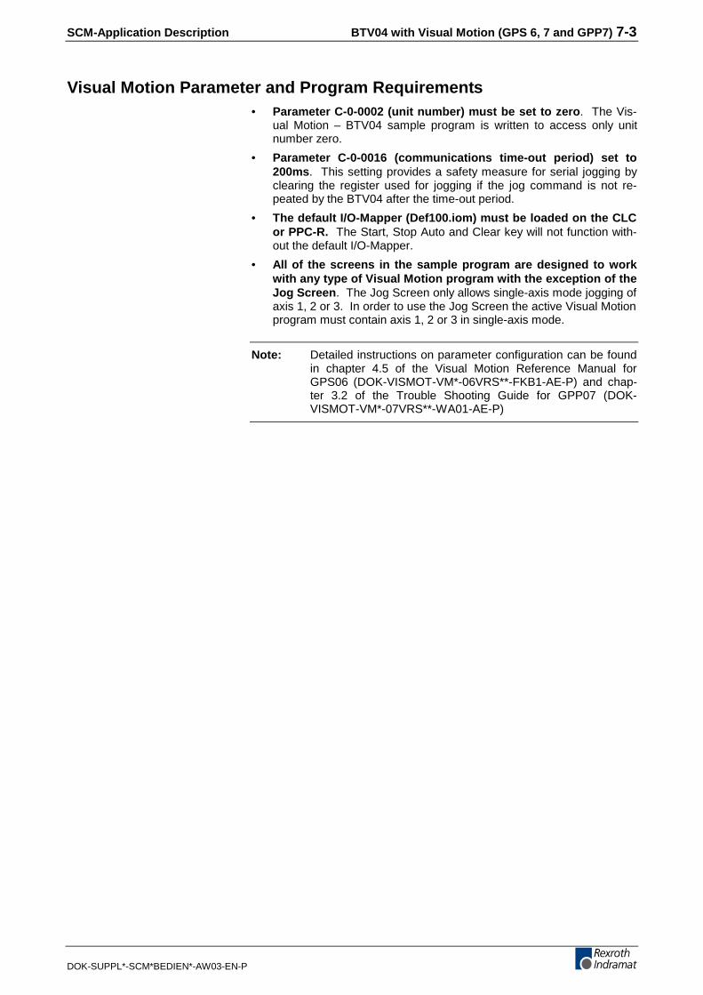
SCM-Application Description BTV04 with Visual Motion (GPS 6, 7 and GPP7) 7-3
DOK-SUPPL*-SCM*BEDIEN*-AW03-EN-P
Visual Motion Parameter and Program Requirements• Parameter C-0-0002 (unit number) must be set to zero. The Vis-
ual Motion – BTV04 sample program is written to access only unitnumber zero.
• Parameter C-0-0016 (communications time-out period) set to200ms. This setting provides a safety measure for serial jogging byclearing the register used for jogging if the jog command is not re-peated by the BTV04 after the time-out period.
• The default I/O-Mapper (Def100.iom) must be loaded on the CLCor PPC-R. The Start, Stop Auto and Clear key will not function with-out the default I/O-Mapper.
• All of the screens in the sample program are designed to workwith any type of Visual Motion program with the exception of theJog Screen. The Jog Screen only allows single-axis mode jogging ofaxis 1, 2 or 3. In order to use the Jog Screen the active Visual Motionprogram must contain axis 1, 2 or 3 in single-axis mode.
Note: Detailed instructions on parameter configuration can be foundin chapter 4.5 of the Visual Motion Reference Manual forGPS06 (DOK-VISMOT-VM*-06VRS**-FKB1-AE-P) and chap-ter 3.2 of the Trouble Shooting Guide for GPP07 (DOK-VISMOT-VM*-07VRS**-WA01-AE-P)

7-4 BTV04 with Visual Motion (GPS 6, 7 and GPP7) SCM-Application Description
DOK-SUPPL*-SCM*BEDIEN*-AW03-EN-P
7.2 General BTV04 Operation
Key DefinitionsThe following table explains the functions of the BTV04 keys.
Key Programmed Function
Alphanumeric keys used for entering data into editfields. Holding down the SHIFT key while pressingthe desired letter accesses the letters. To select thesecond or third letter press the key two or threetimes while holding down the shift key. Releasingthe shift key places the letter then moves to the nextcursor position.
ARROW keys are used to navigate through menuand edit fields.
F1-F6 keys are screen-dependent function keys.
SHIFT key actives the green half of the divided keys.For example [SHIFT] + [7, 7] = B.
START key starts the active Visual Motion programwhile in Auto Mode. (VM Register 100, Bit 4)
AUTO key sets the state of CLC or PPC-R into AutoMode. Active from all screens. (VM Reg. 100, Bit 2)
STOP key stops the running Visual Motion program.Active from all screens. (VM Register 100, Bit 3)
The JOG+ and JOG – keys are used to jog axis 1, 2or 3 in single-axis mode. Only active in the JogScreen.
The PAGEUP and PAGEDOWN keys are used ac-cess next and previous screens.
CLEAR key clears error on CLC or PPC-R. Activeform all screens. (VM Register 100, Bit 5)
HELP key - NOT USED in this application program.
ESC key used to return to a previous screen and toexit out of edit fields.
MAIN MENU key returns to the Main Menu screenfrom any other screen.
OK key is used for accepting selections in menusand edit fields.
Fig. 7-2: Key assignments

SCM-Application Description BTV04 with Visual Motion (GPS 6, 7 and GPP7) 7-5
DOK-SUPPL*-SCM*BEDIEN*-AW03-EN-P
LED DefinitionsThe following key LED’s are used for showing whether or not the key theyare associated with is currently active. (ON = the key is active.) Thescreen displayed on the BTV04 determines their state.
• Function LED’s (F1-F6)
• ESC LED
• Main Menu LED
• OK LED
• JOG+ and JOG- LED’s
The following LED’s are not screen dependent and have meanings otherthan showing key they are associated with is active.
• The Clear LED is ON when the CLC/PPC-R has an error. Deter-mined by the status of VM Register 21, Bit 5 of the CLC/PPC-R.
• The Auto LED is ON when the CLC/PPC-R is in Auto Mode. De-termined by the status of VM Register 100, Bit 2 of the CLC/PPC-R.
• The Start and Stop LED’s are ON only while their keys are beingpressed.
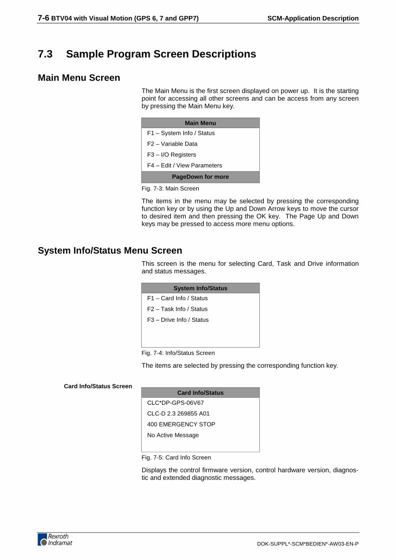
7-6 BTV04 with Visual Motion (GPS 6, 7 and GPP7) SCM-Application Description
DOK-SUPPL*-SCM*BEDIEN*-AW03-EN-P
7.3 Sample Program Screen Descriptions
Main Menu ScreenThe Main Menu is the first screen displayed on power up. It is the startingpoint for accessing all other screens and can be access from any screenby pressing the Main Menu key.
Main Menu
F1 – System Info / Status
F2 – Variable Data
F3 – I/O Registers
F4 – Edit / View Parameters
PageDown for more
Fig. 7-3: Main Screen
The items in the menu may be selected by pressing the correspondingfunction key or by using the Up and Down Arrow keys to move the cursorto desired item and then pressing the OK key. The Page Up and Downkeys may be pressed to access more menu options.
System Info/Status Menu ScreenThis screen is the menu for selecting Card, Task and Drive informationand status messages.
System Info/Status
F1 – Card Info / Status
F2 – Task Info / Status
F3 – Drive Info / Status
Fig. 7-4: Info/Status Screen
The items are selected by pressing the corresponding function key.
Card Info/Status
CLC*DP-GPS-06V67
CLC-D 2.3 269855 A01
400 EMERGENCY STOP
No Active Message
Fig. 7-5: Card Info Screen
Displays the control firmware version, control hardware version, diagnos-tic and extended diagnostic messages.
Card Info/Status Screen

SCM-Application Description BTV04 with Visual Motion (GPS 6, 7 and GPP7) 7-7
DOK-SUPPL*-SCM*BEDIEN*-AW03-EN-P
Task Info/Status
Task A Status Message:
Manual Mode
Task A Diagnostic Message:
Manual Mode
F1=A F2=B F3=C F4=D
Fig. 7-6: Task Info Screen
Displays the Task Status and Diagnostic Messages. The Task is se-lected by using the Function keys.
Info/Status Drive : 1
Drive1
HDD02.1-W040N
HSM1.1-ELS-05V18
A012 Control and power
Sections ready for operation
Fig. 7-7: Drive Info Screen
This screen displays the drive name, type, firmware version and diagnos-tic message. The drive number can be selected by entering the desireddrive number in the edit field and pressing the OK key.
Variable Type Selection ScreenThe menu for selecting the type of variable that is to be viewed/edited.
Select Variable Type
F1 – Floating Point
F2 – Integer
F3 – Global Float
F4 – Global Integer
Fig. 7-8: Variable Screen
The type of variable to be viewed/edited is selected by pressing the corre-sponding Function key.
Note: F1 and F2 refer to currently active program variables only.
Task Info/Status Screen
Drive Info/Status Screen
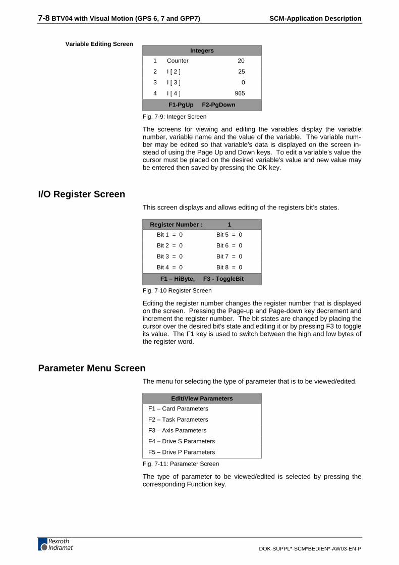
7-8 BTV04 with Visual Motion (GPS 6, 7 and GPP7) SCM-Application Description
DOK-SUPPL*-SCM*BEDIEN*-AW03-EN-P
Integers
1 Counter 20
2 I [ 2 ] 25
3 I [ 3 ] 0
4 I [ 4 ] 965
F1-PgUp F2-PgDown
Fig. 7-9: Integer Screen
The screens for viewing and editing the variables display the variablenumber, variable name and the value of the variable. The variable num-ber may be edited so that variable’s data is displayed on the screen in-stead of using the Page Up and Down keys. To edit a variable’s value thecursor must be placed on the desired variable’s value and new value maybe entered then saved by pressing the OK key.
I/O Register ScreenThis screen displays and allows editing of the registers bit’s states.
Register Number : 1
Bit 1 = 0 Bit 5 = 0
Bit 2 = 0 Bit 6 = 0
Bit 3 = 0 Bit 7 = 0
Bit 4 = 0 Bit 8 = 0
F1 – HiByte, F3 - ToggleBit
Fig. 7-10 Register Screen
Editing the register number changes the register number that is displayedon the screen. Pressing the Page-up and Page-down key decrement andincrement the register number. The bit states are changed by placing thecursor over the desired bit’s state and editing it or by pressing F3 to toggleits value. The F1 key is used to switch between the high and low bytes ofthe register word.
Parameter Menu ScreenThe menu for selecting the type of parameter that is to be viewed/edited.
Edit/View Parameters
F1 – Card Parameters
F2 – Task Parameters
F3 – Axis Parameters
F4 – Drive S Parameters
F5 – Drive P Parameters
Fig. 7-11: Parameter Screen
The type of parameter to be viewed/edited is selected by pressing thecorresponding Function key.
Variable Editing Screen
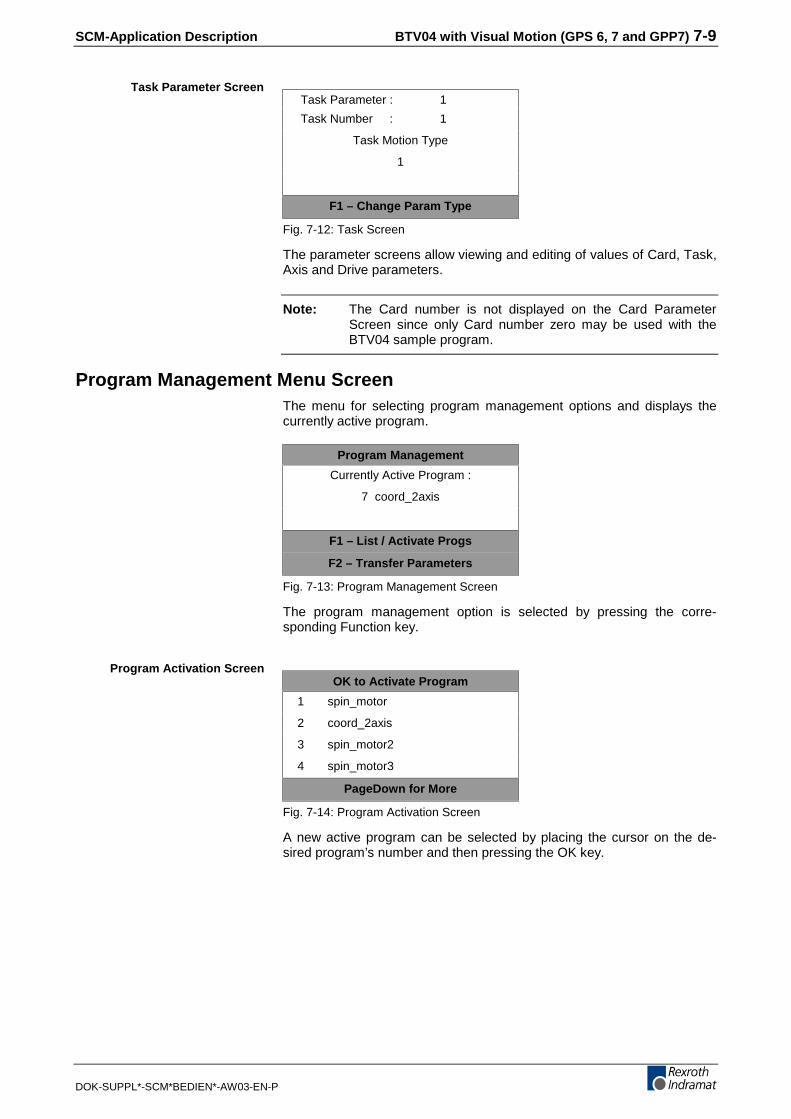
SCM-Application Description BTV04 with Visual Motion (GPS 6, 7 and GPP7) 7-9
DOK-SUPPL*-SCM*BEDIEN*-AW03-EN-P
Task Parameter : 1
Task Number : 1
Task Motion Type
1
F1 – Change Param Type
Fig. 7-12: Task Screen
The parameter screens allow viewing and editing of values of Card, Task,Axis and Drive parameters.
Note: The Card number is not displayed on the Card ParameterScreen since only Card number zero may be used with theBTV04 sample program.
Program Management Menu ScreenThe menu for selecting program management options and displays thecurrently active program.
Program Management
Currently Active Program :
7 coord_2axis
F1 – List / Activate Progs
F2 – Transfer Parameters
Fig. 7-13: Program Management Screen
The program management option is selected by pressing the corre-sponding Function key.
OK to Activate Program
1 spin_motor
2 coord_2axis
3 spin_motor2
4 spin_motor3
PageDown for More
Fig. 7-14: Program Activation Screen
A new active program can be selected by placing the cursor on the de-sired program’s number and then pressing the OK key.
Task Parameter Screen
Program Activation Screen

7-10 BTV04 with Visual Motion (GPS 6, 7 and GPP7) SCM-Application Description
DOK-SUPPL*-SCM*BEDIEN*-AW03-EN-P
Data Transfer
Source Prog(Cur Active)
7 coord_2axis
Destination Program Num :
1
F1 – Execute Transfer
Fig. 7-15: Data Transfer Screen
The data from the currently active program can be transferred to anyother program. The destination program is selected by editing its valueand then pressing the OK key. To execute the data transfer the F1 keymust be pressed
Jogging ScreenAllows Single-Axis Mode jogging of axis 1, 2, or 3. The mode of joggingis set for "continuous jogging” and "fast speed” by the BTV04 setting thecorresponding bits in the Task*_Jog registers. The Task*_Jog register isdependent upon the task each axis is assigned to.
Single Axis Jog Screen
Jogging Axis 1
Position : 5.456
F1 – Axs1 F2 – Axs2 F3 – Axs3
Fig. 7-16: Jogging Screen
To jog an axis the JOG+ and JOG- keys are used. Pressing F1, F2 or F3changes the axis number being jogged.
Data Transfer Screen

SCM-Application Description BTV04 with Visual Motion (GPS 6, 7 and GPP7) 7-11
DOK-SUPPL*-SCM*BEDIEN*-AW03-EN-P
7.4 Problem Solving
Checking for CommunicationsThe Card Info/Status screen can be accessed for the Main Menu screenby pressing the F1 key twice. The Card Info/Status screen will display thecontrol’s firmware version, hardware type and diagnostic message.These items will not be displayed if the BTV04 and CLC/PPC-R are notcommunicating and the following items should be checked.
• The RS-485 cable is connected between connector X2 of the BTV04and the correct connector on the CLC/PPC-R.
• The parameters for the BTV04 and CLC/PPC-R serial ports must beset properly. (Baud rates must match!)
Serial ErrorsError windows are displayed on the BTV04 screen when serial communi-cation errors occur. Requesting non-existent Card, Task, Axis or Driveparameters or if valid parameters are edited with invalid values, causesmost of these errors. To clear these errors the ESC key must bepressed. Entering the wrong value in some screens will cause multipleerrors and the ESC key will have to be pressed several times.
Unable to Enter Jog ScreenThe Jog Screen can only be entered if the control is in manual mode andthe currently active program contains axis 1, 2 or 3 as a single axis modeaxis.

7-12 BTV04 with Visual Motion (GPS 6, 7 and GPP7) SCM-Application Description
DOK-SUPPL*-SCM*BEDIEN*-AW03-EN-P
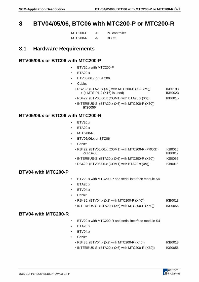
SCM-Application Description BTV04/05/06, BTC06 with MTC200-P or MTC200-R 8-1
DOK-SUPPL*-SCM*BEDIEN*-AW03-EN-P
8 BTV04/05/06, BTC06 with MTC200-P or MTC200-RMTC200-P -> PC controller
MTC200-R -> RECO
8.1 Hardware Requirements
BTV05/06.x or BTC06 with MTC200-P• BTV20.x with MTC200-P
• BTA20.x
• BTV05/06.x or BTC06
• Cable:
• RS232: (BTA20.x (X8) with MTC200-P (X2-SPS)) IKB0193+ (if MTS-P1.2 (X16) is used) IKB0023
• RS422: (BTV05/06.x (COM1) with BTA20.x (X9)) IKB0015
• INTERBUS-S: (BTA20.x (X6) with MTC200-P (X60))IKS0056
BTV05/06.x or BTC06 with MTC200-R• BTV20.x
• BTA20.x
• MTC200-R
• BTV05/06.x or BTC06
• Cable:
• RS422: (BTV05/06.x (COM1) with MTC200-R (PROG)) IKB0015 or RS485: IKB0017
• INTERBUS-S: (BTA20.x (X6) with MTC200-R (X60)) IKS0056
• RS422: (BTV05/06.x (COM1) with BTA20.x (X9)) IKB0015
BTV04 with MTC200-P• BTV20.x with MTC200-P and serial interface module S4
• BTA20.x
• BTV04.x
• Cable:
• RS485: (BTV04.x (X2) with MTC200-P (X40)) IKB0018
• INTERBUS-S: (BTA20.x (X6) with MTC200-P (X60)) IKS0056
BTV04 with MTC200-R• BTV20.x with MTC200-R and serial interface module S4
• BTA20.x
• BTV04.x
• Cable:
• RS485: (BTV04.x (X2) with MTC200-R (X40)) IKB0018
• INTERBUS-S: (BTA20.x (X6) with MTC200-R (X60)) IKS0056

8-2 BTV04/05/06, BTC06 with MTC200-P or MTC200-R SCM-Application Description
DOK-SUPPL*-SCM*BEDIEN*-AW03-EN-P
8.2 Preparing the Typical Application
Commissioning must be prepared by loading the following data in thecontroller and the small operator input unit.
Controller: (via the archiving/backup function of the user interface)
• Machine parameters (Par_arc)
• PLC program (Sps_arc)
• NC program package (NC_arc)
•
BTV04: (via DOLFI)
• B4s03Vxx.ibf-File (firmware)
• Standard_BTV04.ibf (typical program)
The "Standard_BTV04.btv" file must be copied to the directory of the userinterface, \Mt-cnc\Btv_var.
BTV05: (via DOLFI)
• B5s03Vxx.ibf-File (firmware)
• Standard_BTV05.ibf (typical program)
The "Standard_BTV05.btv" file must be copied to the directory of the userinterface, \Mt-cnc\Btv_var.
BTV06: (via DOLFI)
• B6s03Vxx.ibf-File (firmware)
• Standard_BTV06.ibf (typical program)
The "Standard_BTV06.btv" file must be copied to the directory of the userinterface, \Mt-cnc\Btv_var.
BTC06: (via DOLFI)
• C6s03Vxx.ibf-File (firmware)
• Standard_BTC06.ibf (typical program)
The "Standard_BTC06.btv" file must be copied to the directory of the userinterface, \Mt-cnc\Btv_var.
Note: Once the PLC program has been compiled in the PLC pro-gramming system, the NC-STRD1 and Standard_BTxxxMiniMap files must be activated by pressing the space bar inthe Options – BTV status display menu item (identified by apreceding dot) before the program is loaded into the controller.
In general we want to point out that a program's .btv file thatwas created by the ScreenManager must be copied to theabove-mentioned path and be activated if the small operatorinput unit accesses variables of the PLC.
The files in the directory Btv_var are protected by a file dataidentifier. No manual changes are permitted.
Transmission via e-mail also destroys the file! (This is onlypossible in a ZIP format).
If the file is destroyed, this will lead to a file signature errorduring the compilation of the PLC program. In this case, theScreenManager must compile the .scm file to create a new.btv file.
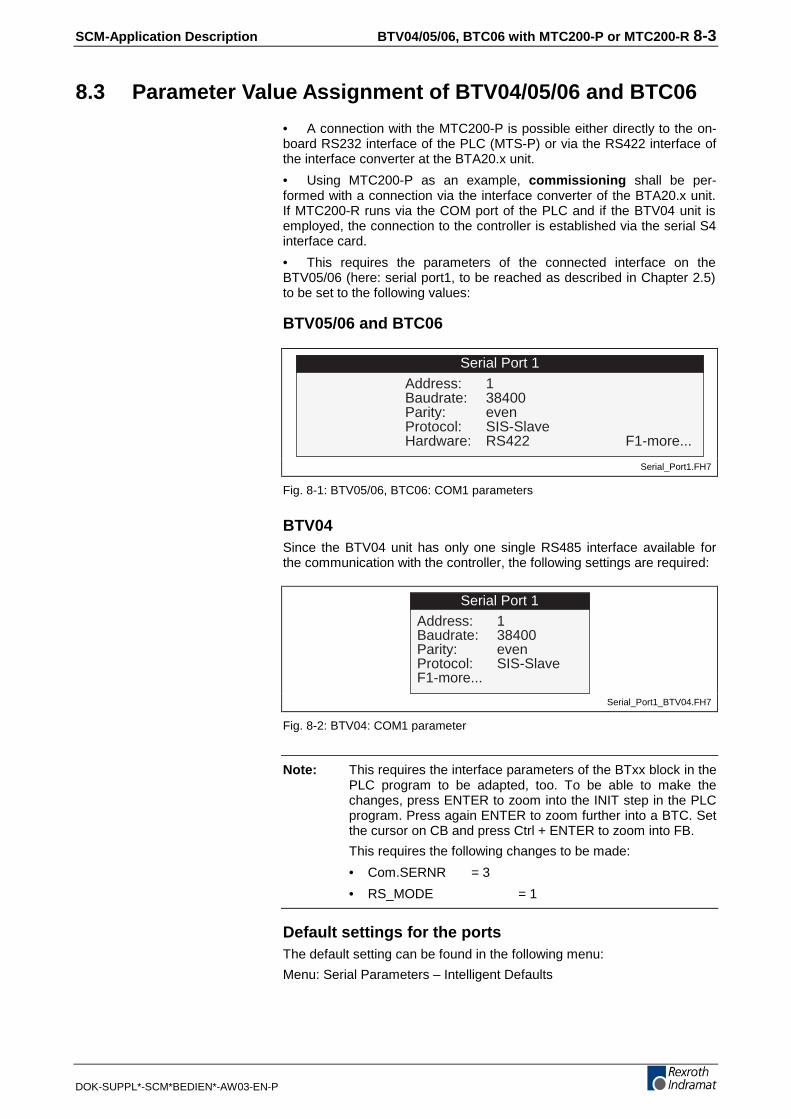
SCM-Application Description BTV04/05/06, BTC06 with MTC200-P or MTC200-R 8-3
DOK-SUPPL*-SCM*BEDIEN*-AW03-EN-P
8.3 Parameter Value Assignment of BTV04/05/06 and BTC06
• A connection with the MTC200-P is possible either directly to the on-board RS232 interface of the PLC (MTS-P) or via the RS422 interface ofthe interface converter at the BTA20.x unit.
• Using MTC200-P as an example, commissioning shall be per-formed with a connection via the interface converter of the BTA20.x unit.If MTC200-R runs via the COM port of the PLC and if the BTV04 unit isemployed, the connection to the controller is established via the serial S4interface card.
• This requires the parameters of the connected interface on theBTV05/06 (here: serial port1, to be reached as described in Chapter 2.5)to be set to the following values:
BTV05/06 and BTC06
Serial Port 1Address: 1Baudrate: 38400Parity: evenProtocol: SIS-SlaveHardware: RS422 F1-more...
Serial_Port1.FH7
Fig. 8-1: BTV05/06, BTC06: COM1 parameters
BTV04Since the BTV04 unit has only one single RS485 interface available forthe communication with the controller, the following settings are required:
Serial Port 1Address: 1Baudrate: 38400Parity: evenProtocol: SIS-SlaveF1-more...
Serial_Port1_BTV04.FH7
Fig. 8-2: BTV04: COM1 parameter
Note: This requires the interface parameters of the BTxx block in thePLC program to be adapted, too. To be able to make thechanges, press ENTER to zoom into the INIT step in the PLCprogram. Press again ENTER to zoom further into a BTC. Setthe cursor on CB and press Ctrl + ENTER to zoom into FB.
This requires the following changes to be made:
• Com.SERNR = 3
• RS_MODE = 1
Default settings for the portsThe default setting can be found in the following menu:
Menu: Serial Parameters – Intelligent Defaults

8-4 BTV04/05/06, BTC06 with MTC200-P or MTC200-R SCM-Application Description
DOK-SUPPL*-SCM*BEDIEN*-AW03-EN-P
8.4 BTxx Function Block
Task The BTxx function block (FB) implements the communication betweenPLC and the HMI control panels BTV04, BTV05 and BTC06 via a serialinterface. I/O data and visualization data is exchanged cyclically in thisprocess.
Note: As a general rule, the BTxx function block should already beprogrammed in the INIT step (initialization) of the PLC pro-gram.
Function block structure
Fig. 8-3: Structure of the BTxx function block
FB inputs ENABLE
The execution of the function block is activated when the ENABLE input isset. The interface opens automatically. An OPEN_COM for the selectedinterface must not be programmed beforehand. This functionality is inte-grated in the FB.
Likewise, clearing this input interrupts the connection to the control paneland closes the interface (no CLOS_COM ).
EN_GUI
The EN_GUI input is used for activating the GUI_SK functionality for thetwo machine control key at the related operator panel
(in preparation; not yet supported by ScreenManager 03Vxx).
EN_GUI DEVICE BTXADR
ENABLE
TO_BTX
BTxx
KEY_L
KEY_R KEY_S1 KEY_S2
FR_BTX
STATE
READY
BOOL COM INT
BOOL
A_B31
BOOL BOOL BOOL
BOOL
A_B31
INT
BOOL
SCM-Application Description BTV04/05/06, BTC06 with MTC200-P or MTC200-R 8-5
DOK-SUPPL*-SCM*BEDIEN*-AW03-EN-P
DEVICE
The Device input contains the parameter record of the employed serialinterface. To achieve a Hamming Distance of four, the parity settingEVEN has been defined for the Indramat communication protocol. Thespecified baud rate is 38400 bit/s.
BTXADR
Station address of the connected operator panel TO_BTX
32-bit input memory for PLC function keys
The applied signals are transmitted to the operator panel as Boolean in-puts for the PLC function keys.
FB outputs KEY_L
Status operator panel machine control key left-hand side KEY_R
Status operator panel machine control key right-hand side KEY_S1
Operator panel specific status bit 1 KEY_S2
Operator panel specific status bit 2 FR_BTX
32-bit output memory for PLC function keys
The applied signals are transmitted from the operator panel as Booleanoutputs for the PLC function keys. STATE
Function block - status :
0: Reset status
1: Check validity of FB input parameter
2: Initialize interface
3: Initialize SIS communication handler
4: Send initialization message frame to operator panel
5: Wait for Initialization acknowledgement from operator panel
6: Communication is active
7: Timeout during communication READY
Communication with operator panel is active
Function block
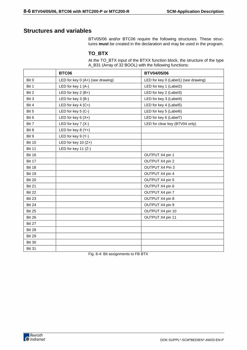
8-6 BTV04/05/06, BTC06 with MTC200-P or MTC200-R SCM-Application Description
DOK-SUPPL*-SCM*BEDIEN*-AW03-EN-P
Structures and variables BTV05/06 and/or BTC06 require the following structures. These struc-tures must be created in the declaration and may be used in the program.
TO_BTX At the TO_BTX input of the BTXX function block, the structure of the typeA_B31 (Array of 32 BOOL) with the following functions:
BTC06 BTV04/05/06
Bit 0 LED for key 0 (A+) (see drawing) LED for key 0 (Label1) (see drawing)
Bit 1 LED for key 1 (A-) LED for key 1 (Label2)
Bit 2 LED for key 2 (B+) LED for key 2 (Label3)
Bit 3 LED for key 3 (B-) LED for key 3 (Label4)
Bit 4 LED for key 4 (C+) LED for key 4 (Label5)
Bit 5 LED for key 5 (C-) LED for key 5 (Label6)
Bit 6 LED for key 6 (X+) LED for key 6 (Label7)
Bit 7 LED for key 7 (X-) LED for clear key (BTV04 only)
Bit 8 LED for key 8 (Y+)
Bit 9 LED for key 9 (Y-)
Bit 10 LED for key 10 (Z+)
Bit 11 LED for key 11 (Z-)
Bit 16 OUTPUT X4 pin 1
Bit 17 OUTPUT X4 pin 2
Bit 18 OUTPUT X4 Pin 3
Bit 19 OUTPUT X4 pin 4
Bit 20 OUTPUT X4 pin 5
Bit 21 OUTPUT X4 pin 6
Bit 22 OUTPUT X4 pin 7
Bit 23 OUTPUT X4 pin 8
Bit 24 OUTPUT X4 pin 9
Bit 25 OUTPUT X4 pin 10
Bit 26 OUTPUT X4 pin 11
Bit 27
Bit 28
Bit 29
Bit 30
Bit 31Fig. 8-4: Bit assignments to FB BTX
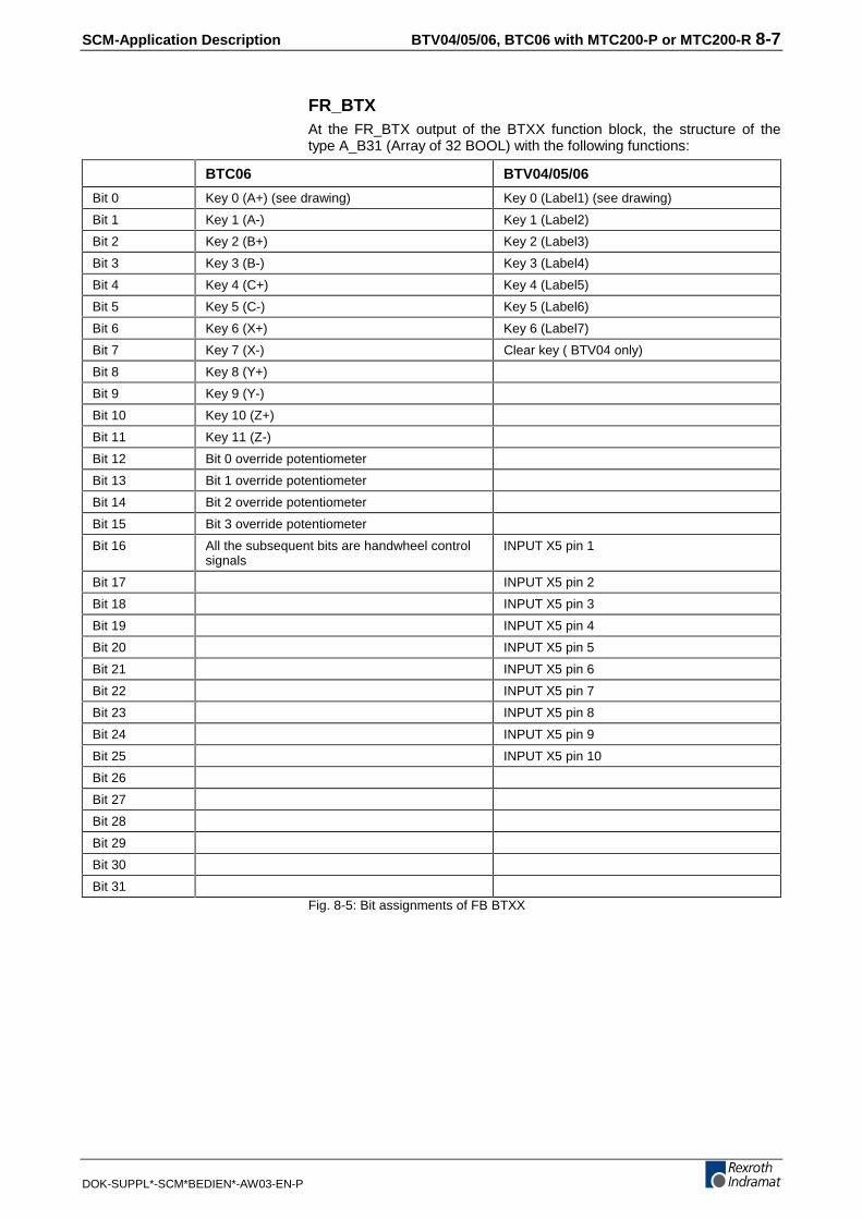
SCM-Application Description BTV04/05/06, BTC06 with MTC200-P or MTC200-R 8-7
DOK-SUPPL*-SCM*BEDIEN*-AW03-EN-P
FR_BTXAt the FR_BTX output of the BTXX function block, the structure of thetype A_B31 (Array of 32 BOOL) with the following functions:
BTC06 BTV04/05/06
Bit 0 Key 0 (A+) (see drawing) Key 0 (Label1) (see drawing)
Bit 1 Key 1 (A-) Key 1 (Label2)
Bit 2 Key 2 (B+) Key 2 (Label3)
Bit 3 Key 3 (B-) Key 3 (Label4)
Bit 4 Key 4 (C+) Key 4 (Label5)
Bit 5 Key 5 (C-) Key 5 (Label6)
Bit 6 Key 6 (X+) Key 6 (Label7)
Bit 7 Key 7 (X-) Clear key ( BTV04 only)
Bit 8 Key 8 (Y+)
Bit 9 Key 9 (Y-)
Bit 10 Key 10 (Z+)
Bit 11 Key 11 (Z-)
Bit 12 Bit 0 override potentiometer
Bit 13 Bit 1 override potentiometer
Bit 14 Bit 2 override potentiometer
Bit 15 Bit 3 override potentiometer
Bit 16 All the subsequent bits are handwheel controlsignals
INPUT X5 pin 1
Bit 17 INPUT X5 pin 2
Bit 18 INPUT X5 pin 3
Bit 19 INPUT X5 pin 4
Bit 20 INPUT X5 pin 5
Bit 21 INPUT X5 pin 6
Bit 22 INPUT X5 pin 7
Bit 23 INPUT X5 pin 8
Bit 24 INPUT X5 pin 9
Bit 25 INPUT X5 pin 10
Bit 26
Bit 27
Bit 28
Bit 29
Bit 30
Bit 31Fig. 8-5: Bit assignments of FB BTXX
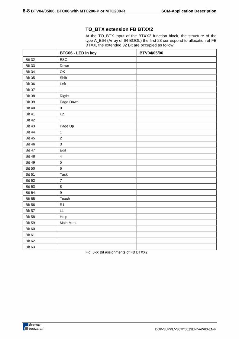
8-8 BTV04/05/06, BTC06 with MTC200-P or MTC200-R SCM-Application Description
DOK-SUPPL*-SCM*BEDIEN*-AW03-EN-P
TO_BTX extension FB BTXX2 At the TO_BTX input of the BTXX2 function block, the structure of thetype A_B64 (Array of 64 BOOL) the first 23 correspond to allocation of FBBTXX, the extended 32 Bit are occupied as follow:
BTC06 - LED in key BTV04/05/06
Bit 32 ESC
Bit 33 Down
Bit 34 OK
Bit 35 Shift
Bit 36 Left
Bit 37 -
Bit 38 Rigtht
Bit 39 Page Down
Bit 40 0
Bit 41 Up
Bit 42 .
Bit 43 Page Up
Bit 44 1
Bit 45 2
Bit 46 3
Bit 47 Edit
Bit 48 4
Bit 49 5
Bit 50 6
Bit 51 Task
Bit 52 7
Bit 53 8
Bit 54 9
Bit 55 Teach
Bit 56 R1
Bit 57 L1
Bit 58 Help
Bit 59 Main Menu
Bit 60
Bit 61
Bit 62
Bit 63Fig. 8-6: Bit assignments of FB BTXX2

SCM-Application Description BTV04/05/06, BTC06 with MTC200-P or MTC200-R 8-9
DOK-SUPPL*-SCM*BEDIEN*-AW03-EN-P
FR_BTX extension FB BTXX2 At the TO_BTX output of the BTXX2 function block, the structure of thetype A_B64 (Array of 64 BOOL) the first 23 correspond to allocation of FBBTXX, the extended 32 Bit are occupied as follow:
BTC06 – key BTV04/05/06
Bit 32 ESC
Bit 33 Down
Bit 34 OK
Bit 35 Shift
Bit 36 Left
Bit 37 -
Bit 38 Rigtht
Bit 39 Page Down
Bit 40 0
Bit 41 Up
Bit 42 .
Bit 43 Page Up
Bit 44 1
Bit 45 2
Bit 46 3
Bit 47 Edit
Bit 48 4
Bit 49 5
Bit 50 6
Bit 51 Task
Bit 52 7
Bit 53 8
Bit 54 9
Bit 55 Teach
Bit 56 R1
Bit 57 L1
Bit 58 Help
Bit 59 Main Menu
Bit 60
Bit 61
Bit 62
Bit 63
Fig. 8-7: Bit assignments of FB BTXX2
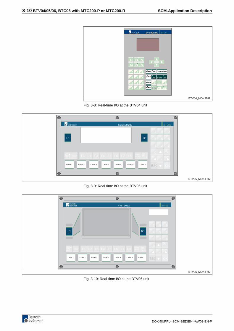
8-10 BTV04/05/06, BTC06 with MTC200-P or MTC200-R SCM-Application Description
DOK-SUPPL*-SCM*BEDIEN*-AW03-EN-P
BTV04_MOK.FH7
Fig. 8-8: Real-time I/O at the BTV04 unit
MAINMENUHELP
L1 R1
Label 6 ESC OK
1 32
0
7ABC
9GHI
8DEF
4JKL
STU
DEL NEXT
6PQR
5MNO
F1 F2 F3 F4 F5 F6 F7 F8-
+
.
VW XYZ
SYSTEM200 BTV05
Label 7Label 6Label 5Label 4Label 3Label 2Label 1
BTV05_MOK.FH7
Fig. 8-9: Real-time I/O at the BTV05 unit
SYSTEM200 BTV06
L1 R1
MAINMENUHELP
Label 6
F1 F2 F3 F4 F5 F6 F7 F8
Label 7Label 6Label 5Label 4Label 3Label 2Label 1 ESC OK
1 32
0
7ABC
9GHI
8DEF
4JKL
STU
DEL NEXT
6PQR
5MNO
-+
.
VW XYZ
BTV06_MOK.FH7
Fig. 8-10: Real-time I/O at the BTV06 unit

SCM-Application Description BTV04/05/06, BTC06 with MTC200-P or MTC200-R 8-11
DOK-SUPPL*-SCM*BEDIEN*-AW03-EN-P
EDIT
TASK
TEACH9
Z+
Y+
X+
Z-
Y-
X-
R1
87
4 5 6
321
0NEXT
OK
-
ESC
F1
L1
A+ A-
B-B+
C+ C-
HELP
ABC
MNO
DEF
PQR
+
GHI
STU VW XYZ
JKL
MAINMENU
F2 F3 F5 F6 F7 F8F4
DEL
.
SYSTEM200 BTC06
%
01
24
68
10 20
120100
8070
6050
4030
Btc_mok.FH7
Fig. 8-11: Real-time I/O at the BTC06 unit
WARNING
The keys highlighted in the figures are con-nected with the function block in serial real-time. This means that all I/O will be set to ZEROwhen communication is interrupted.This also applies to the incremental inputswhen the handwheel function of the BTC06 unitis used. If communication with the BTC06 unitis interrupted while the handwheel function isactive, incorrect programming will lead to a mo-tion of the connected axis.⇒ It must therefore be ensured that the keys are pro-
grammed such that there will be no malfunction ofthe machine if the communication between the smalloperator input unit and the controller is interrupted.
⇒ To avoid unwanted axis movements while the hand-wheel is active, the READY output of the BTxx blockmust be interconnected with the HWACT input of theHNDWHEEL function.

8-12 BTV04/05/06, BTC06 with MTC200-P or MTC200-R SCM-Application Description
DOK-SUPPL*-SCM*BEDIEN*-AW03-EN-P
Parameter value assignment of the BTxx communication function block
�6<67(0����:RUNLQJ�SRVLWLRQ�07&����3�������������������������������������������������� �������������������3/&�SURJUDP�
�%7&B��B��IXQFWLRQ�EORFN��������������������������������������������������������������
�,PSOHPHQWDWLRQ����������������������������������������������������������������������� �07&����3�����9HUVLRQ����������
BTC_06_1
1 ����������� ���������������������������������������������������������������������������������������
����������� � ������ ���������������������������������������������������������������������������������������
���������� �������� FRP�%$8'������������������������������������������������������������������������������
����������� ���������������������������������������������������������������������������������������
19........................... ......................................... .......... ANY_INT
com.BAUD..................... Baud rate................................ .......... INT
2 ����������� ���������������������������������������������������������������������������������������
����������� � ������ ���������������������������������������������������������������������������������������
���������� �������� FRP�'(9,&(����������������������������������������������������������������������������
����������� ���������������������������������������������������������������������������������������
0............................ ........................................ .......... ANY_INT
com.DEVICE................... Device no............................... .......... INT
3 ����������� ���������������������������������������������������������������������������������������
����������� � ������ ���������������������������������������������������������������������������������������
���������� �������� FRP�6(515�����������������������������������������������������������������������������
����������� ���������������������������������������������������������������������������������������
0............................ ........................................ .......... ANY_INT
com.SERNR.................... No. of the serial interface............. .......... INT
4 ����������� ���������������������������������������������������������������������������������������
����������� � ������ ���������������������������������������������������������������������������������������
���������� �������� FRP�6723������������������������������������������������������������������������������
����������� FRP�+$1'6+����������������������������������������������������������������������������
��������������������� FRP�'$7$������������������������������������������������������������������������������
1............................ ........................................ .......... ANY_INT
com.STOP..................... Number of stop bits..................... .......... INT
com.HANDSH................... Software/handshake...................... .......... INT
com.DATA..................... Number of data bits..................... .......... INT
5 ����������� ���������������������������������������������������������������������������������������
����������� � ������ ���������������������������������������������������������������������������������������
���������� �������� FRP�3$5,7<����������������������������������������������������������������������������
����������� ���������������������������������������������������������������������������������������
3............................ ........................................ .......... ANY_INT
com.PARITY................... Parity.................................. .......... INT
6 ����������� ���������������������������������������������������������������������������������������
����������� � ������ ���������������������������������������������������������������������������������������
���������� �������� �35272&2/����������������������������������������������������������������������������
����������� ���������������������������������������������������������������������������������������
4............................ ........................................ .......... ANY_INT
com.PROTOCOL................. Protocol type........................... .......... INT
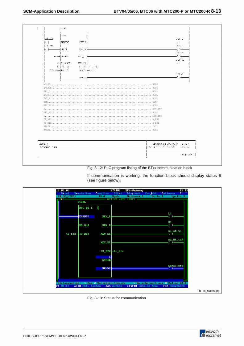
SCM-Application Description BTV04/05/06, BTC06 with MTC200-P or MTC200-R 8-13
DOK-SUPPL*-SCM*BEDIEN*-AW03-EN-P
7 �����������EWY����������������������������������������������������������������������������������������������
����������� ����������������������������������������������������������������������������
����������� %7;;��������������� ����������������������������������������������������������������������������
(1$%/(����� ������������������� �������������������������������������������������������������������.(<B/����
� (1$%/(��������.(<B/ ���
(1B*8,����� ������������������� �������������������������������������������������������������������.(<B5����
� (1B*8,��������.(<B5 ���
����������� ������������������� �������������������������������������������������������������������.(<B6����
�������FRP '(9,&(�������.(<B6� ���
����������� ������������������� �������������������������������������������������������������������.(<B6����
���������� 56B02'(������.(<B6� ���
���������� %7;B$'5������)5B%7; )5B%7;���������������������������������������������������������������������
����72B%7; 72B%7;��������67$7( 67$7(����������������������������������������������������������������������
����������� ������������������� �������������������������������������������������������������������5($'<����
����������� ��������������5($'< ���
����������� ����������������������������������������������������������������������������
btv05........................ ........................................ .......... BTXX
ENABLE....................... ........................................ .......... BOOL
KEY_L........................ ........................................ .......... BOOL
EN_GUI....................... ........................................ .......... BOOL
KEY_R........................ ........................................ .......... BOOL
com.......................... ........................................ .......... COM
KEY_S1....................... ........................................ .......... BOOL
2............................ ........................................ .......... ANY_INT
KEY_S2....................... ........................................ .......... BOOL
1............................ ........................................ .......... ANY_INT
FR_BTX....................... ........................................ .......... A_B31
TO_BTX....................... ........................................ .......... A_B31
STATE........................ ........................................ .......... INT
READY........................ ........................................ .......... BOOL
�07&����������������������������������������������������������������������������� ����&UHDWHG�RQ����������������������
�,1'5$0$7�*PE+������������������������������������������������������������������� �3ULQWHG�RQ�������������������������
���������������������������������������������������������������������������������
��������������������������������������������������������������������������������� ��������������������������3DJH������
Fig. 8-12: PLC program listing of the BTxx communication block
If communication is working, the function block should display status 6(see figure below).
BTxx_state6.jpg
Fig. 8-13: Status for communication
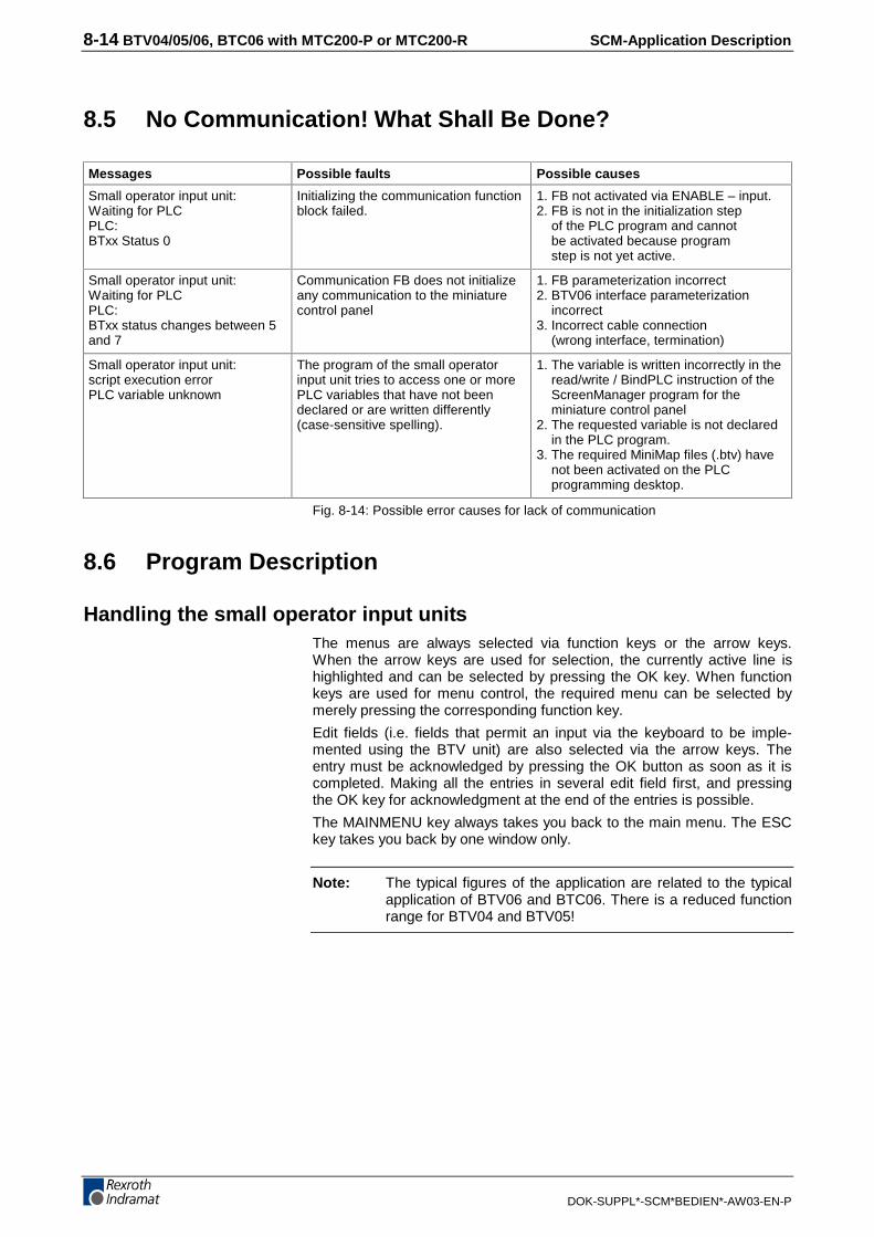
8-14 BTV04/05/06, BTC06 with MTC200-P or MTC200-R SCM-Application Description
DOK-SUPPL*-SCM*BEDIEN*-AW03-EN-P
8.5 No Communication! What Shall Be Done?
Messages Possible faults Possible causes
Small operator input unit:Waiting for PLCPLC:BTxx Status 0
Initializing the communication functionblock failed.
1. FB not activated via ENABLE – input.2. FB is not in the initialization step of the PLC program and cannot be activated because program step is not yet active.
Small operator input unit:Waiting for PLCPLC:BTxx status changes between 5and 7
Communication FB does not initializeany communication to the miniaturecontrol panel
1. FB parameterization incorrect2. BTV06 interface parameterization incorrect3. Incorrect cable connection (wrong interface, termination)
Small operator input unit:script execution errorPLC variable unknown
The program of the small operatorinput unit tries to access one or morePLC variables that have not beendeclared or are written differently(case-sensitive spelling).
1. The variable is written incorrectly in the read/write / BindPLC instruction of the ScreenManager program for the miniature control panel2. The requested variable is not declared in the PLC program.3. The required MiniMap files (.btv) have not been activated on the PLC programming desktop.
Fig. 8-14: Possible error causes for lack of communication
8.6 Program Description
Handling the small operator input unitsThe menus are always selected via function keys or the arrow keys.When the arrow keys are used for selection, the currently active line ishighlighted and can be selected by pressing the OK key. When functionkeys are used for menu control, the required menu can be selected bymerely pressing the corresponding function key.
Edit fields (i.e. fields that permit an input via the keyboard to be imple-mented using the BTV unit) are also selected via the arrow keys. Theentry must be acknowledged by pressing the OK button as soon as it iscompleted. Making all the entries in several edit field first, and pressingthe OK key for acknowledgment at the end of the entries is possible.
The MAINMENU key always takes you back to the main menu. The ESCkey takes you back by one window only.
Note: The typical figures of the application are related to the typicalapplication of BTV06 and BTC06. There is a reduced functionrange for BTV04 and BTV05!

SCM-Application Description BTV04/05/06, BTC06 with MTC200-P or MTC200-R 8-15
DOK-SUPPL*-SCM*BEDIEN*-AW03-EN-P
Keys of the small operator input unitsSubmenus or input fields are usually selected via function keys or thearrow keys. Exceptions to this rule are shown by a text on the display.
Numeric values or alphabetical characters are entered via the numerickeys 0-9 (Caution: dual assignment of the keys!). Pressing the Shift keyat the same time activates the (alphabetical) keys on a green background.
BTV05/06 and BTC06Keys Function in the program
Menu and function selection. Keys are always explainedby a text on the display.
1 32
0
7ABC
9GHI
8DEF
4JKL
STU
6PQR
5MNO
-+
.
VW XYZ
Used for entering and editing numbers and text. Pressingthe [Shift] key at the same time activates the letters on agreen background. Pressing the key repeatedly shows theletters in succession. Release the [Shift] key to accept theletter last pressed.
Z+
Y+
X+
Z-
Y-
X-A+ A-
B-B+
C+ C-
BTC06 onlyDirect jogging (moving) of axes.
Shift key is activated when a double-assigned key (dualcolor keys) is pressed at the same time.
To acknowledge an inputs and/or a selected menu item.
Goes back by one screen, or aborts an entry.
Used for navigating within the user interface.
Used for rapid navigating within the user interface.
Invokes a help menu at any point of the program (pro-vided that a help menu has been stored).
Jumps to the main menu from any point in the program.
Fig. 8-15: Key assignments
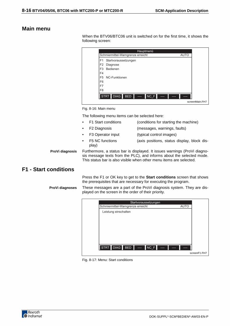
8-16 BTV04/05/06, BTC06 with MTC200-P or MTC200-R SCM-Application Description
DOK-SUPPL*-SCM*BEDIEN*-AW03-EN-P
Main menuWhen the BTV06/BTC06 unit is switched on for the first time, it shows thefollowing screen:
HauptmenüSchmiermittel-Warngrenze erreicht AUTO
F1 StartvoraussetzungenF2 DiagnoseF3 BedienenF4F5 NC-FunktionenF6F7F8
STRT DIAG BED ---- NC_F ---- ---- ----
screenMain.FH7
Fig. 8-16: Main menu
The following menu items can be selected here:
• F1 Start conditions (conditions for starting the machine)
• F2 Diagnosis (messages, warnings, faults)
• F3 Operator input (typical control images)
• F5 NC functions (axis positions, status display, block dis-play)
Furthermore, a status bar is displayed. It issues warnings (ProVi diagno-sis message texts from the PLC), and informs about the selected mode.This status bar is also visible when other menu items are selected.
F1 - Start conditionsPress the F1 or OK key to get to the Start conditions screen that showsthe prerequisites that are necessary for executing the program.
These messages are a part of the ProVi diagnosis system. They are dis-played on the screen in the order of their priority.
StartvoraussetzungenSchmiermittel-Warngrenze erreicht AUTO
Leistung einschalten
STRT DIAG BED ---- NC_F ---- ---- ----
screenF1.FH7
Fig. 8-17: Menu: Start conditions
ProVi diagnosis
ProVi diagnoses
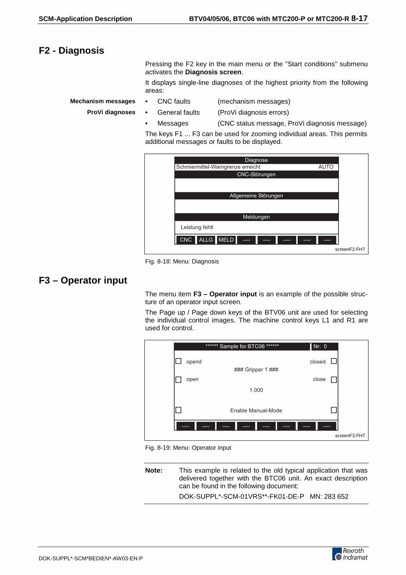
SCM-Application Description BTV04/05/06, BTC06 with MTC200-P or MTC200-R 8-17
DOK-SUPPL*-SCM*BEDIEN*-AW03-EN-P
F2 - DiagnosisPressing the F2 key in the main menu or the "Start conditions" submenuactivates the Diagnosis screen.
It displays single-line diagnoses of the highest priority from the followingareas:
• CNC faults (mechanism messages)
• General faults (ProVi diagnosis errors)
• Messages (CNC status message, ProVi diagnosis message)
The keys F1 ... F3 can be used for zooming individual areas. This permitsadditional messages or faults to be displayed.
DiagnoseSchmiermittel-Warngrenze erreicht AUTO
CNC ALLG MELD ---- ---- ---- ---- ----
CNC-Störungen
Allgemeine Störungen
Meldungen
Leistung fehlt
screenF2.FH7
Fig. 8-18: Menu: Diagnosis
F3 – Operator inputThe menu item F3 – Operator input is an example of the possible struc-ture of an operator input screen.
The Page up / Page down keys of the BTV06 unit are used for selectingthe individual control images. The machine control keys L1 and R1 areused for control.
****** Sample for BTC06 ******
opend
---- ---- ---- ---- ---- ---- ---- ----
Nr: 0
open
closed
close
### Gripper 1 ###
1.000
Enable Manual-Mode
screenF3.FH7
Fig. 8-19: Menu: Operator input
Note: This example is related to the old typical application that wasdelivered together with the BTC06 unit. An exact descriptioncan be found in the following document:
DOK-SUPPL*-SCM-01VRS**-FK01-DE-P MN: 283 652
Mechanism messages
ProVi diagnoses

8-18 BTV04/05/06, BTC06 with MTC200-P or MTC200-R SCM-Application Description
DOK-SUPPL*-SCM*BEDIEN*-AW03-EN-P
F5 – NC functions (BTC06 and BTV06 only)Press F5 to get to the NC screen.
The base screen of the menu contains the axis position display, and in-forms of the active NC program (program memory), the active NC block,and status messages.
The menu also permits the screen to be adapted with respect to axis andcolumn selection for the axis data, and the selection of program or ma-chine coordinates via the F7 and F8 function keys. To increase the per-formance of axis data updating, this menu also permits the NC statusmessage and the active NC block to be hidden. This setup menu can alsobe invoked from any other screen by pressing the SHIFT + OK keys.Pressing the ESC key always returns the display to the NC base screen.
NC-FunktionenSchmiermittel-Warngrenze erreicht AUTO
XYZS1
STAT SATZ VAR EVTS NPV D-KR SET-A SET-B
A01 Leistung fehltN0000 .START [START]
Soll [ mm ]-967.945
-1935.890-2903.836
0.000
Ist [ mm ]-967.945
-1935.890-2903.836
0.000
End [ mm ]-967.945
-1935.890-2903.836
0.000
screenF5.FH7
Fig. 8-20: Menu: NC functions
The representation of additional NC functions has been implemented byan additional selection of function keys F1..F8.
They permit the following menus to be selected:
• F1 STAT Status display
• F2 SATZ Block display
• F3 VAR NC variables (not implemented in this example)
• F4 EVTS NC events (not implemented in this example)
• F5 NPV Zero offsets (not implemented in this example)
• F6 D-KR D corrections
• F7 SETA Setup of axis selection, process number selection
• F8 SETB Setup of axis data column selection; toggling betweenmachine coordinates/program coordinates
F5 – F1 Status displayThe status display informs about the major NC functions.
The following parameters are represented:
• Active
• Active D correction number
• Active zero offset table
• Active tool number
• Active tool edge number
• Next preselected tool number
• Active G codes
• Active M codes
• Active feed override
Axis positions
Status display

SCM-Application Description BTV04/05/06, BTC06 with MTC200-P or MTC200-R 8-19
DOK-SUPPL*-SCM*BEDIEN*-AW03-EN-P
• Active spindle override
• Programmed feed rate
• Actual feed rate
• Programmed spindle speed
• Actual spindle speed
• Active rapid traverse override
• Actual acceleration
STAT
NC-StatusRAD
SATZ VAR EVTS NPV D-KR ---- NC-F
OVR 100%S1 100%
D 0 O 0 T 0 E 1 Tsel 0
G01 G17 G40 G53G15 G90 G94 G97G71 G43 G62 G98G47 G09 G07 ---G30 G72 G78 G68G36 G25 --- ------ --- --- ------ --- --- ---
M030 ---- ---- ----M005 ---- ---- M040M205 ---- ---- M240M305 ---- ---- M340
F 0.0 mm/minFact 0.0 mm/minS1 0.0 1/minS1act 0.0 1/minROV 100% ACC 100%
screenF5_F1.FH7
Fig. 8-21: Menu: NC status display
F5 – F2 block displayAs a maximum, the block display menu shows the active NC block, andthe three NC blocks before and after the active NC block. The active NCblock is framed.
SATZ
SatzanzeigeSchmiermittel-Warngrenze erreicht AUTO
N0000 .START [START]
N0001 RAD D0
N0002 G01 X0.0 Y0.0 Z0.0 F10000.0
N0003 S133.0 M003
STAT VAR EVTS NPV D-KR ---- NC-F
A01
screenF5_F2.FH7
Fig. 8-22: Menu: Block display
Block display

8-20 BTV04/05/06, BTC06 with MTC200-P or MTC200-R SCM-Application Description
DOK-SUPPL*-SCM*BEDIEN*-AW03-EN-P
F5 – F6 D correctionsThis menu permits D corrections to be selected and edited.
To select the D correction number and to edit the correction data, movethe cursor via the arrow keys and enter the values via the numeric key-pad.
D-KRSATZ
D-KorrekturenSchmiermittel-Warngrenze erreicht AUTO
L1 3.0000 mm mm
L2 0.0000 mm 0.0000 mm
L3 0.0000 mm 0.0000 mm
R 0.0000 mm 0.0000 mm
STAT VAR EVTS NPV ---- NC-F
3.0000
D-Korr. Nr: 1 Editierung:
screenF5_F6.FH7
Fig. 8-23: Menu: D corrections
8.7 Output of ProVi Diagnoses
ProVi diagnoses can only be displayed if they are programmed in thePLC. The related programming instructions can be found in the followingdocuments:
• DOK-MTC200-DIAG*PROVI*-ANW1-DE-P MN: 00281324
• DOK-MTC200-DIAG*PROVI*-ANW1-EN-P MN: 00281325
Basically, the diagnoses are displayed by linking a STRING variable to aPLC function block (FB for start conditions, FB for messages, FB forwarnings, FB for errors). The FBs contain arrays that have numbers as-signed. The related text (comment line in the PLC program) is displayedwhen the condition of a number is satisfied. These texts are then avail-able in the order of their priority.
Linking such a function block and specifying the priority enables the textsto be displayed on the miniature control panel.
The command syntax is described in the ScreenManager documentation.
Note: If ProVi diagnoses are programmed in the PLC program, aMiniMap file is created when the PLC program is compiled.This file must then be activated under Options->BTV statusdisplay before the program is loaded into the controller. If thefile has not been activated, an attempt of accessing this datawill lead to a "script execution error" in the BTV06.
D corrections

SCM-Application Description BTV04/05/06, BTC06 with MTC200-P or MTC200-R 8-21
DOK-SUPPL*-SCM*BEDIEN*-AW03-EN-P
Example of programming ProVi diagnosesExcerpt from the typical application from ScreenManager
/******************************** F1 - Start conditions *********************************/
void Screen1(){
Screen(); // new initialization of screen and functionsunScreen = 1; // set variable to valueunScreen.WritePLC(_PLC("BILD")); // write BTV value to PLC variableTextAttr(1,1,0,0,1); // view following text inverted and centricText(0,0,240,10,strF1); // víew string
TextAttr(1,0,0,0,0); // set following text leftstrSPStxt1.BindProViPLC("fbStart_",0); // link string variable to PLC function block cyclically updated, priority: higheststrSPStxt2.BindProViPLC("fbStart_",1); // link string variable to PLC function block cyclically updatedstrSPStxt3.BindProViPLC("fbStart_",2); // link string variable to PLC function block cyclically updatedstrSPStxt4.BindProViPLC("fbStart_",3); // link string variable to PLC function block cyclically updatedstrSPStxt5.BindProViPLC("fbStart_",4); // link string variable to PLC function block cyclically updatedstrSPStxt6.BindProViPLC("fbStart_",5); // link string variable to PLC function block cyclically updatedstrSPStxt7.BindProViPLC("fbStart_",6); // link string variable to PLC function block cyclically updated, priority: lowest
strSPStxt1.Display(10,27,220,0,0,0); // display stringstrSPStxt2.Display(10,40,220,0,0,0); // display stringstrSPStxt3.Display(10,53,220,0,0,0); // display stringstrSPStxt4.Display(10,66,220,0,0,0); // display stringstrSPStxt5.Display(10,79,220,0,0,0); // display stringstrSPStxt6.Display(10,92,220,0,0,0); // display stringstrSPStxt7.Display(10,105,220,0,0,0); // display string
StatusLine(); // call function
Key(32,1,Screen2); // call function if key is pressedKey(33,1,Screen3); // call function if key is pressedKey(34,1,Screen4); // call function if key is pressedKey(35,1,Screen5_standard); // call function if key is pressedKey(36,1,Screen6); // call function if key is pressed
TextAttr(1,0,0,0,1); // view following text centricText(2,118,26,10,strMaintxt1); // víew stringTextAttr(1,1,0,0,1); // view following text inverted and centricText(2,118,26,10,strMaintxt1); // víew stringText(32,118,26,10,strMaintxt2); // víew stringText(62,118,26,10,strMaintxt3); // víew stringText(92,118,26,10,strMaintxt4); // víew stringText(122,118,26,10,strMaintxt5); // víew stringText(152,118,26,10,strMaintxt6); // víew string
if(unErr == 1){
Diagnostic(); // call function if variable is 1}
}
Fig. 8-24: ScreenManager program excerpt for programming ProVi diagnoses
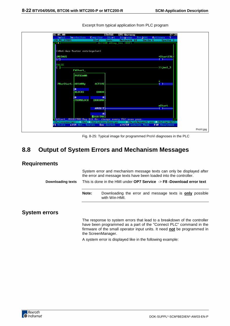
8-22 BTV04/05/06, BTC06 with MTC200-P or MTC200-R SCM-Application Description
DOK-SUPPL*-SCM*BEDIEN*-AW03-EN-P
Excerpt from typical application from PLC program
ProVi.jpg
Fig. 8-25: Typical image for programmed ProVi diagnoses in the PLC
8.8 Output of System Errors and Mechanism Messages
RequirementsSystem error and mechanism message texts can only be displayed afterthe error and message texts have been loaded into the controller.
This is done in the HMI under OP7 Service -> F8 -Download error text
Note: Downloading the error and message texts is only possiblewith Win-HMI.
System errorsThe response to system errors that lead to a breakdown of the controllerhave been programmed as a part of the "Connect PLC" command in thefirmware of the small operator input units. It need not be programmed inthe ScreenManager.
A system error is displayed like in the following example:
Downloading texts
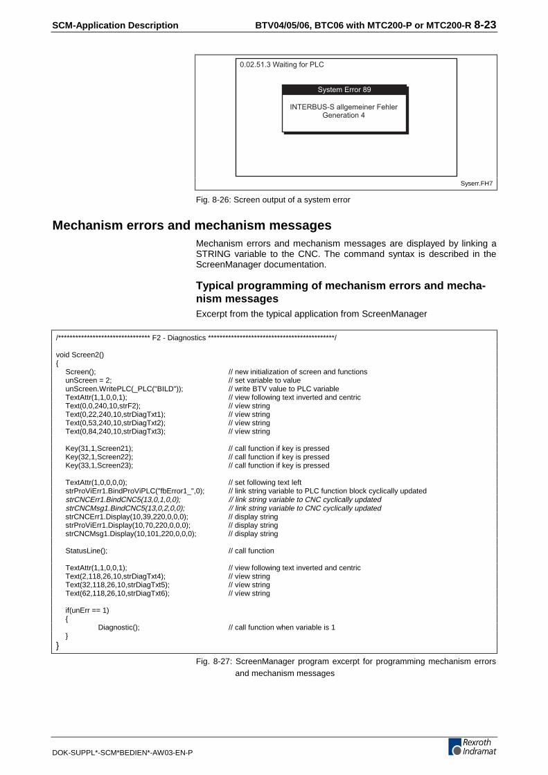
SCM-Application Description BTV04/05/06, BTC06 with MTC200-P or MTC200-R 8-23
DOK-SUPPL*-SCM*BEDIEN*-AW03-EN-P
0.02.51.3 Waiting for PLC
System Error 89
INTERBUS-S allgemeiner FehlerGeneration 4
Syserr.FH7
Fig. 8-26: Screen output of a system error
Mechanism errors and mechanism messagesMechanism errors and mechanism messages are displayed by linking aSTRING variable to the CNC. The command syntax is described in theScreenManager documentation.
Typical programming of mechanism errors and mecha-nism messagesExcerpt from the typical application from ScreenManager
/******************************** F2 - Diagnostics ********************************************/
void Screen2(){
Screen(); // new initialization of screen and functionsunScreen = 2; // set variable to valueunScreen.WritePLC(_PLC("BILD")); // write BTV value to PLC variableTextAttr(1,1,0,0,1); // view following text inverted and centricText(0,0,240,10,strF2); // víew stringText(0,22,240,10,strDiagTxt1); // víew stringText(0,53,240,10,strDiagTxt2); // víew stringText(0,84,240,10,strDiagTxt3); // víew string
Key(31,1,Screen21); // call function if key is pressedKey(32,1,Screen22); // call function if key is pressedKey(33,1,Screen23); // call function if key is pressed
TextAttr(1,0,0,0,0); // set following text leftstrProViErr1.BindProViPLC("fbError1_",0); // link string variable to PLC function block cyclically updatedstrCNCErr1.BindCNC5(13,0,1,0,0); // link string variable to CNC cyclically updatedstrCNCMsg1.BindCNC5(13,0,2,0,0); // link string variable to CNC cyclically updatedstrCNCErr1.Display(10,39,220,0,0,0); // display stringstrProViErr1.Display(10,70,220,0,0,0); // display stringstrCNCMsg1.Display(10,101,220,0,0,0); // display string
StatusLine(); // call function
TextAttr(1,1,0,0,1); // view following text inverted and centricText(2,118,26,10,strDiagTxt4); // víew stringText(32,118,26,10,strDiagTxt5); // víew stringText(62,118,26,10,strDiagTxt6); // víew string
if(unErr == 1){
Diagnostic(); // call function when variable is 1}
}
Fig. 8-27: ScreenManager program excerpt for programming mechanism errorsand mechanism messages

8-24 BTV04/05/06, BTC06 with MTC200-P or MTC200-R SCM-Application Description
DOK-SUPPL*-SCM*BEDIEN*-AW03-EN-P

SCM-Application Description BTC06 with DLC01.1 9-1
DOK-SUPPL*-SCM*BEDIEN*-AW03-EN-P
9 BTC06 with DLC01.1
9.1 Device settings
Basic settings on the BTC06 unitTo get to the BTC06 parameter menu, use the following procedure:
1. Simultaneously press the [Shift]+[ESC] key combination
2. Next, keep the F2 key on the BTC06 unit depressed
To be able to communicate with the DLC you must make the followingselections:
1. Press the F1 key "Serial Port Parameter"
2. Press the F1 key "Intelligent Defaults"
3. Press the F1 key "Set Indramat CLC/CLM" (the settings for CLMand DLC are identical).
4. Press the ESC key three times
5. Press the F3 key "Save Values and Reboot".
This parameter setup can also be used for making manual selections atthe ports.
Increase the delay time in the BTC06 unit from 4ms to 8ms if you en-counter any problems in changing DLC parameters via the BTC06 unit.
DLC settingsIn the "DLC_BTC06" example, the axis can be moved via the keys X+and X- of the BTC06 unit. This requires the two bits in the DLC parameterB001 to be set that permit jogging via the serial interface. Otherwise, thekeys will not be interrogated. Furthermore, the DLC’s time-out valueshould be increased to 9 (parameter B004).
B001 = 011000000
The selected interface must be RS485.
B003 = 0960 4 1 8 1
The station number can be specified via the DLC parameter B004. Forthe example "DLC_BTC06", it must be set to address 1. The checksumverification must be OFF, the interface confirmation ON.
B004 = 1 1 01 0 9 02
Axis teach-in
Interface selection

9-2 BTC06 with DLC01.1 SCM-Application Description
DOK-SUPPL*-SCM*BEDIEN*-AW03-EN-P
9.2 Summary of the Major Points
• The cables are connected
• 24V control voltage is applied to the BTC06 unit
• Dolfi is installed on the PC (Dolfi 1V05, or later)
• Runtime must be loaded on the BTC06 unit
• DLC and BTC06 must both be set to RS485
• The baud rate between BTC06 and DLC must be identical
BTC06 port selections:
Serial port 1 Serial port 2
Address: 1 3
Baud rate: 9600 9600
Parity: Off Off
Protocol: ASCII ASCII + SIS
Hardware: RS485 /
Delay: 4 0
Timeout: 500 400
Retry: 20 2
Group no. 0 0
Max. unit: 0 0
Fig. 9-1: BTC06 port selections
DLC parameters
Parameter Contents
B001 01100000
B003 0960 4 1 8 1
B004 1 1 01 0 9 04
Fig. 9-2: DLC parameters
ScreenManagerThe "DLC_BTC06" application is written for a BTC06 unit. Thus, it cannot directly be transferred to a BTV unit.
If the ScreenManager application is downloaded from the ScreenManagerprogramming desktop, the following points must be observed:
Are there problems with downloading ? Å Under the "Tools/Project"menu item, change from "TargetType" BTV to "TargetType" BTC. Theaddress (default for BTC06=3) that has been selected in the BTC06 portsettings must also be selected in the download tool Dolfi.
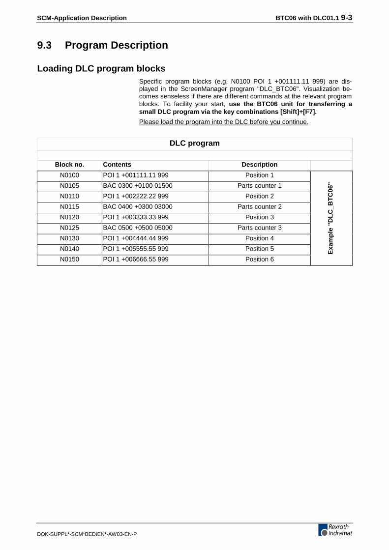
SCM-Application Description BTC06 with DLC01.1 9-3
DOK-SUPPL*-SCM*BEDIEN*-AW03-EN-P
9.3 Program Description
Loading DLC program blocksSpecific program blocks (e.g. N0100 POI 1 +001111.11 999) are dis-played in the ScreenManager program "DLC_BTC06". Visualization be-comes senseless if there are different commands at the relevant programblocks. To facility your start, use the BTC06 unit for transferring asmall DLC program via the key combinations [Shift]+[F7].
Please load the program into the DLC before you continue.
DLC program
Block no. Contents Description
N0100 POI 1 +001111.11 999 Position 1
N0105 BAC 0300 +0100 01500 Parts counter 1
N0110 POI 1 +002222.22 999 Position 2
N0115 BAC 0400 +0300 03000 Parts counter 2
N0120 POI 1 +003333.33 999 Position 3
N0125 BAC 0500 +0500 05000 Parts counter 3
N0130 POI 1 +004444.44 999 Position 4
N0140 POI 1 +005555.55 999 Position 5
N0150 POI 1 +006666.55 999 Position 6
Exa
mp
le "
DL
C_B
TC
06"
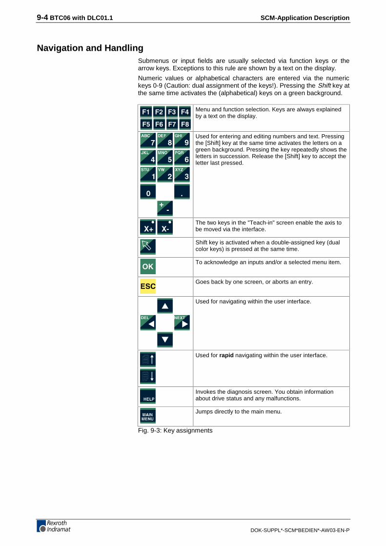
9-4 BTC06 with DLC01.1 SCM-Application Description
DOK-SUPPL*-SCM*BEDIEN*-AW03-EN-P
Navigation and HandlingSubmenus or input fields are usually selected via function keys or thearrow keys. Exceptions to this rule are shown by a text on the display.
Numeric values or alphabetical characters are entered via the numerickeys 0-9 (Caution: dual assignment of the keys!). Pressing the Shift key atthe same time activates the (alphabetical) keys on a green background.
Menu and function selection. Keys are always explainedby a text on the display.
Used for entering and editing numbers and text. Pressingthe [Shift] key at the same time activates the letters on agreen background. Pressing the key repeatedly shows theletters in succession. Release the [Shift] key to accept theletter last pressed.
The two keys in the "Teach-in" screen enable the axis tobe moved via the interface.
Shift key is activated when a double-assigned key (dualcolor keys) is pressed at the same time.
To acknowledge an inputs and/or a selected menu item.
Goes back by one screen, or aborts an entry.
Used for navigating within the user interface.
Used for rapid navigating within the user interface.
Invokes the diagnosis screen. You obtain informationabout drive status and any malfunctions.
Jumps directly to the main menu.
Fig. 9-3: Key assignments

SCM-Application Description BTC06 with DLC01.1 9-5
DOK-SUPPL*-SCM*BEDIEN*-AW03-EN-P
Menu
Main menuAfter power-on, the BTC06 first displays a selection screen.
Main menu
F1=Position input
F2=Quantity
F3=Drive information
F4=Program overview
F5=Inputs/outputs
F6=Diagnosis
F7=DLC parameters
F8=Teach-in
Fig. 9-4: Main menu display
Use the arrow keys or, directly, the function keys to select the requiredsubmenu.
The branches in the following description always start from the mainmenu and go towards the submenus.
Position input
Editing positionsSix program positions are stored in this example. The corresponding pro-gram commands are in the DLC blocks N0100, N0110; N0120, N0130,N0140, and N0150.
To go from the main menu to the position input menu:
• F1 =Position input
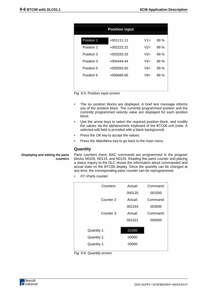
9-6 BTC06 with DLC01.1 SCM-Application Description
DOK-SUPPL*-SCM*BEDIEN*-AW03-EN-P
Position input
Position 1 +001111.11 V1= 99 %
Position 2 +002222.22 V2= 99 %
Position 3 +003333.33 V3= 99 %
Position 4 +004444.44 V4= 99 %
Position 5 +005555.55 V5= 99 %
Position 6 +006666.66 V6= 99 %
Fig. 9-5: Position input screen
• The six position blocks are displayed. A brief text message informsyou of the position block. The currently programmed position and thecurrently programmed velocity value are displayed for each positionblock.
• Use the arrow keys to select the required position block, and modifythe values via the alphanumeric keyboard of the BTC06 unit (note: Aselected edit field is provided with a black background).
• Press the OK key to accept the values.
• Press the MainMenu key to go back to the main menu
QuantityParts counters (here: BAC command) are programmed in the programblocks N0105, N0115, and N0125. Reading this parts counter and placinga status inquiry to the DLC shows the information about commanded andactual state on the BTC06 display. Since the quantity can be changed atany time, the corresponding parts counter can be reprogrammed.
• F2 =Parts counter
Counters Actual: Command:
000125 001500
Counter 2 Actual: Command:
002154 003000
Counter 3 Actual: Command:
001521 005000
Quantity 1: 01500
Quantity 1: 03000
Quantity 1: 05000
Fig. 9-6: Quantity screen
Displaying and editing the partscounters

SCM-Application Description BTC06 with DLC01.1 9-7
DOK-SUPPL*-SCM*BEDIEN*-AW03-EN-P
• The three parts counters are displayed with the command and actualstates. A brief text message tells you which parts counter is dis-played. Each parts counter has an edit filed assigned that permits thequantity to be changed.
• Use the arrow keys to select the required parts counter (e.g. quantity2), and change the value via the alphanumeric keyboard of theBTC06 unit (note: A selected edit field is provided with a black back-ground).
• Press the OK key to accept the values.
• Press the MainMenu key to go back to the main menu
Drive information• F3 =Drive information
Position A+000357.47 mm
Position lag +000000.00 mm
Speed 0000.00 rpm
Firmware version
DLC1.1-DA1-04VRS
Fig. 9-7: Drive information screen
You obtain information about position, position lag, speed and firm-ware version.
Displaying drive information
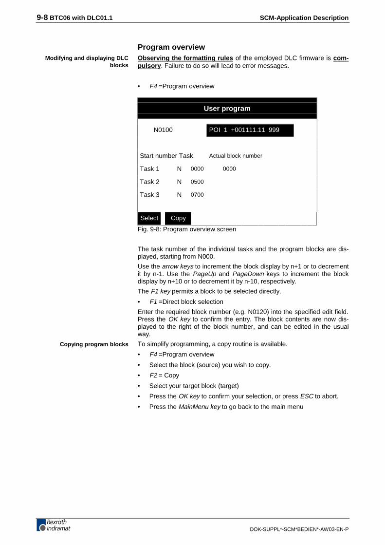
9-8 BTC06 with DLC01.1 SCM-Application Description
DOK-SUPPL*-SCM*BEDIEN*-AW03-EN-P
Program overviewObserving the formatting rules of the employed DLC firmware is com-pulsory. Failure to do so will lead to error messages.
• F4 =Program overview
User program
N0100 POI 1 +001111.11 999
Start number Task Actual block number
Task 1 N 0000 0000
Task 2 N 0500
Task 3 N 0700
Select Copy
Fig. 9-8: Program overview screen
The task number of the individual tasks and the program blocks are dis-played, starting from N000.
Use the arrow keys to increment the block display by n+1 or to decrementit by n-1. Use the PageUp and PageDown keys to increment the blockdisplay by n+10 or to decrement it by n-10, respectively.
The F1 key permits a block to be selected directly.
• F1 =Direct block selection
Enter the required block number (e.g. N0120) into the specified edit field.Press the OK key to confirm the entry. The block contents are now dis-played to the right of the block number, and can be edited in the usualway.
To simplify programming, a copy routine is available.
• F4 =Program overview
• Select the block (source) you wish to copy.
• F2 = Copy
• Select your target block (target)
• Press the OK key to confirm your selection, or press ESC to abort.
• Press the MainMenu key to go back to the main menu
Modifying and displaying DLCblocks
Copying program blocks
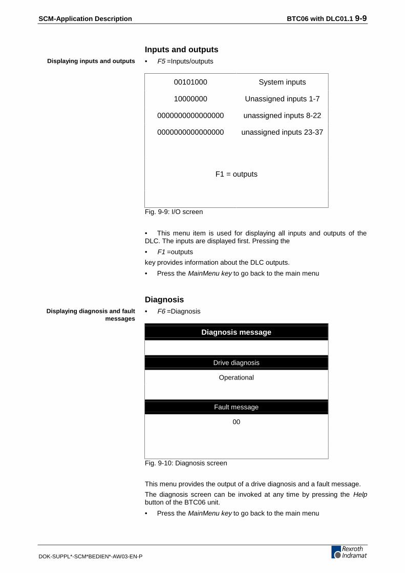
SCM-Application Description BTC06 with DLC01.1 9-9
DOK-SUPPL*-SCM*BEDIEN*-AW03-EN-P
Inputs and outputs• F5 =Inputs/outputs
00101000 System inputs
10000000 Unassigned inputs 1-7
0000000000000000 unassigned inputs 8-22
0000000000000000 unassigned inputs 23-37
F1 = outputs
Fig. 9-9: I/O screen
• This menu item is used for displaying all inputs and outputs of theDLC. The inputs are displayed first. Pressing the
• F1 =outputs
key provides information about the DLC outputs.
• Press the MainMenu key to go back to the main menu
Diagnosis• F6 =Diagnosis
Diagnosis message
Drive diagnosis
Operational
Fault message
00
Fig. 9-10: Diagnosis screen
This menu provides the output of a drive diagnosis and a fault message.
The diagnosis screen can be invoked at any time by pressing the Helpbutton of the BTC06 unit.
• Press the MainMenu key to go back to the main menu
Displaying inputs and outputs
Displaying diagnosis and faultmessages

9-10 BTC06 with DLC01.1 SCM-Application Description
DOK-SUPPL*-SCM*BEDIEN*-AW03-EN-P
Parameters
Attention: Any changes of the parameter values have an effect on themachine interpretation and may damage the machine or be-come a hazard to man or machine. Changes are only possi-ble in parameter mode.
• F7 =DLC parameters
Axis-related parameter
A100 00210000
F1 = B parameter
F2 = C parameter
Fig. 9-11: Parameter screen
Beginning with A100, the display of the A parameters appears. Use thearrow keys up/down (n�1) or the Page keys (n�10) scroll the parametersup or down. Use the arrow key RIGHT to jump to the parameter edit fieldto make changes. Press the OK key to accept the changes.
Use the function keys to select B and C parameters within this screen.
• F1 =B parameter
• F2 =C parameter
Displaying and modifying DLCparameters

SCM-Application Description BTC06 with DLC01.1 9-11
DOK-SUPPL*-SCM*BEDIEN*-AW03-EN-P
Teach-in• F8 =Position teach-in
Preselect the teach-in positions
Actual position +001234.56
1=Position 1 +001111.11
2=Position 2 +002222.22
3=Position 3 +003333.33
4=Position 4 +004444.44
5=Position 5 +005555.55
6=Position 6 +006666.66
Fig. 9-12: Position input screen
The current position and the six programmed position blocks are dis-played. The axes are moved via the X+ and X- keys of the BTC06 unit.
Use the following procedure to teach-in a position:
• Use the arrow keys or, directly, the figures 1 through 6 to select therequired position block.
• Use the X+ and X- keys to move the axis to the required position.Important: The power must be connected and the drive must be inAF.
• The actual position value can be monitored via the BTC06 display.
• Press the OK key to branch to a submenu in which you can eitheraccept the position (press OK) or abort the process (press the ESCkey).
• In either case (accepting the position or aborting), you return to the"Teach-in menu".
• Press the MainMenu key to go back to the main menu.
Position teach-in

9-12 BTC06 with DLC01.1 SCM-Application Description
DOK-SUPPL*-SCM*BEDIEN*-AW03-EN-P
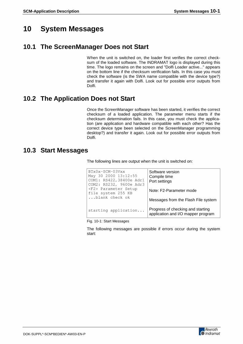
SCM-Application Description System Messages 10-1
DOK-SUPPL*-SCM*BEDIEN*-AW03-EN-P
10 System Messages
10.1 The ScreenManager Does not Start
When the unit is switched on, the loader first verifies the correct check-sum of the loaded software. The INDRAMAT logo is displayed during thistime. The logo remains on the screen and "Dolfi Loader active..." appearson the bottom line if the checksum verification fails. In this case you mustcheck the software (is the SWA name compatible with the device type?)and transfer it again with Dolfi. Look out for possible error outputs fromDolfi.
10.2 The Application Does not Start
Once the ScreenManager software has been started, it verifies the correctchecksum of a loaded application. The parameter menu starts if thechecksum determination fails. In this case, you must check the applica-tion (are application and hardware compatible with each other? Has thecorrect device type been selected on the ScreenManager programmingdesktop?) and transfer it again. Look out for possible error outputs fromDolfi.
10.3 Start Messages
The following lines are output when the unit is switched on:
BTx0x-SCM-03VxxMay 30 2000 13:12:55COM1: RS422,38400e Adr1COM2: RS232, 9600e Adr3<F2> Parameter Setupfile system 255 KB...blank check ok
starting application...
Software versionCompile timePort settings
Note: F2-Parameter mode
Messages from the Flash File system
Progress of checking and startingapplication and I/O mapper program
Fig. 10-1: Start Messages
The following messages are possible if errors occur during the systemstart:
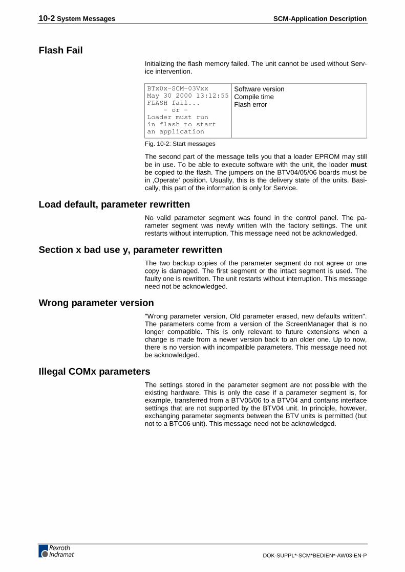
10-2 System Messages SCM-Application Description
DOK-SUPPL*-SCM*BEDIEN*-AW03-EN-P
Flash FailInitializing the flash memory failed. The unit cannot be used without Serv-ice intervention.
BTx0x-SCM-03VxxMay 30 2000 13:12:55FLASH fail... – or –Loader must runin flash to startan application
Software versionCompile timeFlash error
Fig. 10-2: Start messages
The second part of the message tells you that a loader EPROM may stillbe in use. To be able to execute software with the unit, the loader mustbe copied to the flash. The jumpers on the BTV04/05/06 boards must bein ‚Operate' position. Usually, this is the delivery state of the units. Basi-cally, this part of the information is only for Service.
Load default, parameter rewrittenNo valid parameter segment was found in the control panel. The pa-rameter segment was newly written with the factory settings. The unitrestarts without interruption. This message need not be acknowledged.
Section x bad use y, parameter rewrittenThe two backup copies of the parameter segment do not agree or onecopy is damaged. The first segment or the intact segment is used. Thefaulty one is rewritten. The unit restarts without interruption. This messageneed not be acknowledged.
Wrong parameter version"Wrong parameter version, Old parameter erased, new defaults written".The parameters come from a version of the ScreenManager that is nolonger compatible. This is only relevant to future extensions when achange is made from a newer version back to an older one. Up to now,there is no version with incompatible parameters. This message need notbe acknowledged.
Illegal COMx parametersThe settings stored in the parameter segment are not possible with theexisting hardware. This is only the case if a parameter segment is, forexample, transferred from a BTV05/06 to a BTV04 and contains interfacesettings that are not supported by the BTV04 unit. In principle, however,exchanging parameter segments between the BTV units is permitted (butnot to a BTC06 unit). This message need not be acknowledged.

SCM-Application Description System Messages 10-3
DOK-SUPPL*-SCM*BEDIEN*-AW03-EN-P
Flash Erase ErrorThe attempt of initializing the Flash File system failed. Reformatting theflash failed too. This message may be acknowledged, but the file systemwill not be available. As a remedial action, press F6 to try again an overallclearing of the file system under Flash status in the parameter menu. Ifthis fails too, contact the Service Hotline.
10.4 Error Messages During Operation
More or less fatal errors can occur during operation. The messages de-scribed in this chapter are generated within the operating system and can- in contrast to the Script Execution Errors (next chapter) - not be unam-biguously assigned to a program location. They occur either during thestart or during background processing.
"Press any key..." indicates that program execution can be continued in amore or less unrestricted way after a key has been pressed. "Press anykey to reboot..." means that the program cannot be continued and thatthere will be a restart after the key has been pressed.
CNC telegram not supportedThe BindCNC or ReadCNC command was used in conjunction with aninvalid first parameter. The selected service is not available. If the loadedapplication works on other control panels, check whether the latestScreenManager Runtime is loaded. If this is the case, search the applica-tion for a CNC command with invalid parameters. Program execution iscontinued. The MTC inquiry concerned is discarded.
EEPROM erase time-outThis error only occurs when parameters are written in the BTC06 unit.The EEPROM could not be erased. There may be a hardware fault if thiserror occurs repeatedly.
EEPROM write time-outThis error only occurs when parameters are written in the BTC06 unit.The EEPROM could not be written to without errors. There may be ahardware fault if this error occurs repeatedly.
Fatal ReadMiniMapStringThis error may not occur under normal circumstances. When this faultoccurs, please send the ScreenManager application together with thepacked MTC project archive to Indramat.
Fatal LoadProViDataThis error may not occur under normal circumstances. When this faultoccurs, please send the ScreenManager application together with thepacked MTC project archive to Indramat.
10-4 System Messages SCM-Application Description
DOK-SUPPL*-SCM*BEDIEN*-AW03-EN-P
Flash write error"Warning: FlashStoreList(), Flash write error". An error occurred when alist was stored in the Flash File system. The list concerned could not bestored permanently. In this case, check the file system in the corre-sponding parameter menu item, and reformat if necessary.
Handle was not validInitiated by CloseList or EraseList in conjunction with an invalid (alreadyreleased?) handle. Program execution can be continued without any re-strictions.
Insert line not supportedThe InsertLine function is not yet supported by the present ScreenMan-ager version. Program execution can be continued after a key has beenhit.
Map file create errorOpening a Flash File for the MTC MiniMap File failed. Check the file sys-tem in the parameter menu. Note the error messages that occur duringthe overall deletion of the flash. Other possible cause – the loaded appli-cation is so large that there is no more space for the Flash File system.Observe the specifications of free memory space during the start of theunit. Using the MTC at the control panel requires a minimum of 64 KByteto be reported for the Flash File system.
Map file write errorWriting to the Flash File for the MTC MiniMap File failed. Check the filesystem in the parameter menu. Note the error messages that occur dur-ing the overall deletion of the flash.
MTC-Longident wrong sizeThe length of the long ident that is returned from the MTC is invalid.Please check whether the employed versions of ScreenManager andMTC are compatible with each other. The MTC version V20 (WinPCL) isnot yet supported by the ScreenManager version 03Vxx and may causethis error message to be issued.
No ASCII port for CLC"No ASCII port for CLC, off-line mode only, press any key..." The applica-tion requests a ConnectCLC but the "ASCII" protocol has not been se-lected at any interface of the control panel. Communication with the CLCcannot be established. Program execution can be continued in off linemode after a key has been hit. Use the parameter menu for configuring aport for the ASCII protocol or - the easiest solution - activate theCLC/CLM base settings in the "Intelligent Defaults".
Note: This behavior can deliberately be used for executing aScreenManager program without a controller and still withouterror messages (for demonstrations, testing the menu struc-ture, simulations, etc.). At both ports, merely select a protocolthat is different to ASCII.

SCM-Application Description System Messages 10-5
DOK-SUPPL*-SCM*BEDIEN*-AW03-EN-P
No ASCII port for CLM"No ASCII port for CLM, off-line mode only, press any key..." The applica-tion requests a ConnectCLM but the "ASCII" protocol has not been se-lected at any interface of the control panel. Communication toCLM/DLC/ELC-ASCII cannot be established. Program execution can becontinued in off line mode after a key has been hit. Use the parametermenu for configuríng a port for the ASCII protocol or - the easiest solution- activate the CLC/CLM base settings in the "Intelligent Defaults".
Note: This behavior can deliberately be used for executing aScreenManager program without a controller and still withouterror messages (for demonstrations, testing the menu struc-ture, simulations, etc.). At both ports, merely select a protocolthat is different to ASCII.
No more list handlesThere are no more handles available for a new list (requested by the ap-plication using GetFreeList). The total number of simultaneously openhandles is limited to 50 RAM and 50 FLASH handles. The most frequentcause is surely that releasing handles was forgotten in the application orthat a new list was allocated cyclically (e.g. in a Refresh or Event Script -programming error).
No more list memoryThe maximum available memory space was exceeded when data wasinserted in a list or when a new list was created, Possible causes Theamount of data stored in the list was really too large – monitor the value of"FreeMemoryList" in the application in this case. There are 80 KByteavailable for user lists. Another reason can be that releasing unused listswas forgotten in the application so that a larger data quantity has accu-mulated that is no longer required. Fatal programming error in the appli-cation. Program execution is aborted.
No SIS master port for ELC"No SIS master port for ELC, off-line mode only, press any key..." Theapplication requests a ConnectELC but a "SIS master" or "ASCII" protocolhas not been selected at any interface of the control panel. (If anSIS_Master Port is not available, the software tries to establish a contactto an ELC via the ASCII protocol). Establishing communication to the ELCis not possible at all. Program execution can be continued in off line modeafter a key has been hit. Use the parameter menu for configuring a portfor the SIS master protocol or - the easiest solution - activate the ELCbase settings in the "Intelligent Defaults".
Note: This behavior can deliberately be used for executing aScreenManager program without a controller and still withouterror messages (for demonstrations, testing the menu struc-ture, simulations, etc.). At both ports, merely select a protocolthat is different to SIS Master and ASCII.

10-6 System Messages SCM-Application Description
DOK-SUPPL*-SCM*BEDIEN*-AW03-EN-P
No SIS master port for DKC"No SIS master port for DKC, off-line mode only, press any key..." Theapplication requests a ConnectDKC but a "SIS master" or "ASCII" proto-col has not been selected at any interface of the control panel. Communi-cation to DKC cannot be established at all. Program execution can becontinued in off line mode after a key has been hit. Use the parametermenu for configuríng a port for the SIS master protocol or - the easiestsolution - activate the Ecodrive base settings in the "Intelligent Defaults".
Note: This behavior can deliberately be used for executing aScreenManager program without a controller and still withouterror messages (for demonstrations, testing the menu struc-ture, simulations, etc.). At both ports, merely select a protocolthat is different to SIS Master.
No SIS master port for ELC, no real-time connection"No SIS master port for ELC, no real-time connection, press any key..."The application requests a ConnectELC for a specific station number buta "SIS master" protocol has not been selected at any interface of thecontrol panel. Although communication with the ELC can be establishedvia the ASCII protocol, establishing a real-time connection is not possible.Program execution can be continued without real-time connection after akey has been hit. Use the parameter menu for configuríng a port for theSIS master protocol or - the easiest solution - activate the ELC base set-tings in the "Intelligent Defaults".
Not enough RAM for list buffersThis message appears immediately after the system is switched on.There is not enough RAM available for initializing the list function. Thismessage should only appear in test versions. In this case, load the last(previous) version that could be started without any problems.
Only parameter not implementedThe "WriteNCELC" command was used with a single command parame-ter, but there was no new command specified for the line concerned.Thus, ScreenManager does not know which formatting rules are to beapplied for the single parameter. "WriteNCELC" can only be used forwriting complete program blocks. Program execution is continued in thebackground; the error window can be acknowledged with any key. Thereis no write access to the ELC.

SCM-Application Description System Messages 10-7
DOK-SUPPL*-SCM*BEDIEN*-AW03-EN-P
Parameter write failSaving the parameters in the parameter menu failed. Repeated occur-rence of this error indicates a faulty hardware. Working with the unit is stillpossible. Editing parameters is no longer possible.
Serial recursive call"Serial recursive call, CLM driver error, press any key to reboot." This isan internal procedure error of the CLM/ELC drive that occurs when pro-gram blocks are written. This error should never occur during normal op-eration. Press any key to restart the control panel. In this case, pleasesend the application concerned together with a brief description to IN-DRAMAT.
Wrong list handle rA function that is used for reading from lists was invoked with an invalidlist handler. Fatal programming error in the application. Program execu-tion is aborted.
Wrong list handle wA function that is used for writing to lists was invoked with an invalid listhandler. Fatal programming error in the application. Program execution isaborted.
Wrong read offset from CNCThe controller returned an incorrect response to a sequence inquiry to theMTC200 for system fault messages, mechanism messages, or programlines. This error can not usually occur. Please send the application to-gether with an error description and the version descriptions of Screen-Manager Runtime and MTC firmware to INDRAMAT.
10.5 Script Execution Errors
Array overflowA specified array index exceeded the dimensioned array size. This is aprogramming error in the application program.
Bp underflowFatal address error in the virtual machine. The base pointer leaves thestack area. A possible cause can be that local variables exceeded themaximum stack size (please check the local variable declarations andtest by incrementing the stack size of the project options), or a binarycode that was generated incorrectly by the compiler. In this case you musttry to compile the program again with some modifications.
Divided by 0There was a division by 0. Error in the application program.
Illegal segmentFatal address error in the virtual machine. The specified segment doesnot exist. Possible cause: A binary code that was incorrectly generated bythe compiler. In this case you must try to compile the program again withsome modifications. Upgrading to ScreenManager user interface version3 is strongly recommended.

10-8 System Messages SCM-Application Description
DOK-SUPPL*-SCM*BEDIEN*-AW03-EN-P
Jump out of segmentFatal address error in a jump call in the virtual machine. The code seg-ment was exited by a jump address. Possible cause: A binary code thatwas incorrectly generated by the compiler. In this case you must try tocompile the program again with some modifications. Upgrading toScreenManager user interface version 3 is strongly recommended.
Out of segmentGeneral address error in the virtual machine. A possible cause can bethat local variables exceeded the maximum stack size (please check thelocal variable declarations and test by incrementing the stack size of theproject options), or a binary code that was generated incorrectly by thecompiler. The latter chiefly occurs in conjunction with compiler versionV01 and an excessive amount of global data. In this case you must try tocompile the program again with some modifications. Upgrading toScreenManager user interface version 3 is strongly recommended.
Stack overflowAddress error. Invocating a function and/or generating data in the stack.The stack pointer leaves the stack area. A possible cause can be thatlocal variables exceeded the maximum stack size (please check the localvariable declarations and test by incrementing the stack size of the projectoptions), or a binary code that was generated incorrectly by the compiler.In this case you must try to compile the program again with some modifi-cations. Upgrading to ScreenManager user interface version 3 is stronglyrecommended.
Stack underflowAddress error during the return jump from a function. The stack pointerleaves the stack area. A possible cause can be that local variables ex-ceeded the maximum stack size (please check the local variable declara-tions and test by incrementing the stack size of the project options), or abinary code that was generated incorrectly by the compiler. In this caseyou must try to compile the program again with some modifications. Up-grading to ScreenManager user interface version 3 is strongly recom-mended.
R-stack overflowThe return stack overflowed. The maximum call depth of the virtual ma-chine is 250 recursive calls. This number was exceeded. Usually, thismessage is caused by an inadvertent recursion (where a function callsitself). At any case, there is an error in the application program.
Unknown opcodeThe virtual machine encountered an unknown machine command. Possi-ble causes: A binary code that was incorrectly generated by the compiler,or a complete confusion of the machine caused by fatal programmingerrors. In this case you must try to compile the program again with somemodifications. Upgrading to ScreenManager user interface version 3 isstrongly recommended.
Unknown system callThe application called a system function that has not yet been defined inthe ScreenManager Runtime version that is installed in the control panel.Please upgrade to the latest version.

SCM-Application Description System Messages 10-9
DOK-SUPPL*-SCM*BEDIEN*-AW03-EN-P
10.6 Script Execution Error - Fatal I/O Error
The following errors occur with I/O operations. In most messages, anadditional text informs of the exact cause of the error and the Screen-Manager command that caused it.
IO elc string too longFatal error when a program block was built up using the "WriteNCELC"command. This error should not occur when the current software versionis used. It points to an incorrect ELC format list. Please send the Screen-Manager application together with an error description and all firm-ware/software versions to INDRAMAT.
Illegal IO accessAn invalid address was specified in an access to the I/O register area ofthe ScreenManager I/O mapper.
PLC variable unknownThe specified ISP variable could not be found in the MiniMap file of thecontroller. Please check whether all necessary BTV files have been se-lected in the "BTV status display" menu item and whether a new down-load to the controller has been performed. MTC/ISP control variables canonly be accessed if they have been reported to the ISP programmingdesktop via this way.
No more edit cellsThe maximum number (= 50) of simultaneous active links to Dis-play/Edit/Menu item fields was exceeded. In most cases, the cause is asimple programming error: A display, menu item, or edit command isused illegally within a refresh or event script and thus activated repeat-edly. This becomes obvious by a "strange" behavior of the cursor (severalfields overlap...). This message appears after a few seconds/minutes.

10-10 System Messages SCM-Application Description
DOK-SUPPL*-SCM*BEDIEN*-AW03-EN-P
No more serial buffersThe maximum number of simultaneous cyclic active links to control vari-ables was exceeded. The maximum values are 50/70 for MTC/ISP andan additional 50 for the remaining controllers. Higher values are not pos-sible (and not expedient either for performance reasons). The data up-dating time is already in the range of seconds. The most frequent causeis a simple programming error: A bind command is used illegally within arefresh or event script and thus activated repeatedly. This manifests itselfby a gradually slowed down communication, and by this message thatappears after a few minutes.
Type not supportedThe Event function was used with a variable different than UINT16.
or
The requested variable type of the controller is not supported or cannot beconverted into a ScreenManager type. If possible, declare a different typein the controller.
Variable must be globalAn attempt was made to use a local variable together with a Read, BindDisplay, Edit or Event command. All these system calls store the addressof the transferred variable and process it in the background. This worksonly with global variables that remain valid after the script function hasbeen executed. In conjunction with the compiler version 1, this messagecan rarely be issued for global variables. Upgrading to ScreenManageruser interface version 3 is strongly recommended in this case. As an im-mediate aid, compile the program with fewer global variables.
Wrong map file entryAn entry that cannot be interpreted was detected in the MiniMap file thatwas loaded from the MTC/ISP. Download the ISP program again. If thisdoes not help, please send the packed MTC project archive together withthe ScreenManager application and a brief error description to IN-DRAMAT.
Wrong PLC answer lengthA data package received from the ISP is not of the expected length. Havethe version number of ScreenManager and MTC/ISP checked for com-patibility. If the error occurs again, please send the packed MTC projectarchive together with the ScreenManager application and a brief errordescription to INDRAMAT.

SCM-Application Description System Messages 10-11
DOK-SUPPL*-SCM*BEDIEN*-AW03-EN-P
10.7 I/O Error Window
In the event of an incorrect serial access, the ScreenManager activatesan error window that usually shows error texts and numbers from theconnected controllers. Due to own error handling routines, this error win-dow may be overloaded in the ScreenManager application. Depending onthe loaded application, it therefore does not always appear in the de-scribed form.
(Error text)(Transmitted message frame)(Received message frame)
Press ESC to cancelor any key to repeat
Fig. 10-3: Window of the "default Error Handlers" for serial errors
These errors are always related to one serial request. Except for thecases listed below, the error text comes from the connected controller.Where controllers with ASCII protocols are concerned, the transmittedand the received message frames provide additional information that canbe used for locating the fault and its cause in the documents. Where con-trollers with binary protocol are concerned, these two lines contain ahexadecimal dump of the first characters of the message frame thatcaused the problem.
Press "ESC" to acknowledge. This clears the request from the buffer.Program execution is continued without having read or written this vari-able.
Pressing any other key for acknowledgment repeats the request. If, forexample, the connection to the controller was interrupted, acknowledgingthis window will cause the communication to be resumed at the pointwhere it was interrupted. No write or read access will be lost.
CLC is not respondingThe connected CLC VisualMotion has not responded to a request. Usingthe time-out selected in the parameters, the request was repeated asmany times as is specified in the retry parameter.
CLM is not respondingThe connected CLM, DLC or ELC has not responded to a request. Usingthe time-out selected in the parameters, the request was repeated asmany times as is specified in the retry parameter.
CNC answer too shortThe MTC has replied to a protocol with too short a message frame. Thiserror should not occur during normal operation when the current softwareversions are employed.
CNC NAK xx yyThe MTC has replied to a protocol with an NAK. The two numbers xx andyy inform about the error number. Please refer to the MTC publication forfurther information.
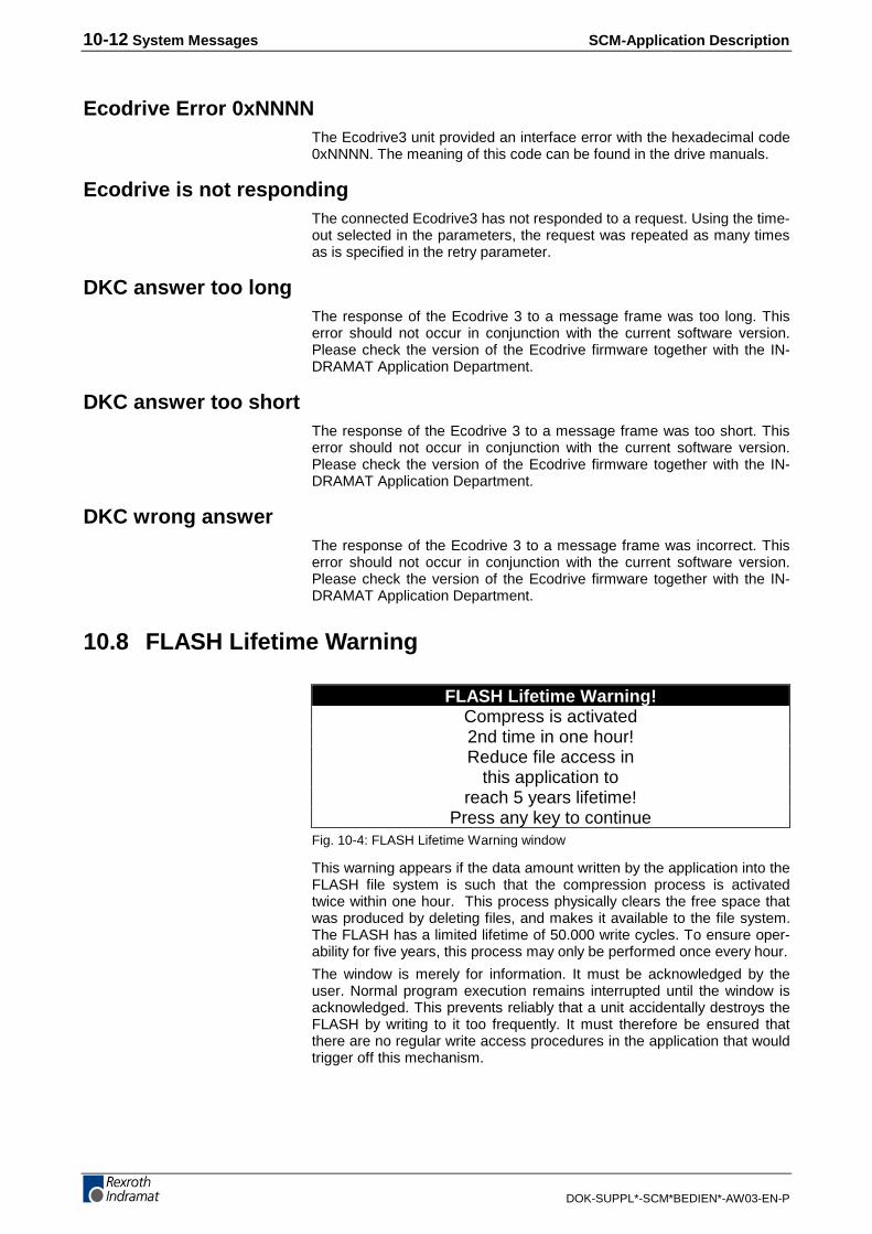
10-12 System Messages SCM-Application Description
DOK-SUPPL*-SCM*BEDIEN*-AW03-EN-P
Ecodrive Error 0xNNNNThe Ecodrive3 unit provided an interface error with the hexadecimal code0xNNNN. The meaning of this code can be found in the drive manuals.
Ecodrive is not respondingThe connected Ecodrive3 has not responded to a request. Using the time-out selected in the parameters, the request was repeated as many timesas is specified in the retry parameter.
DKC answer too longThe response of the Ecodrive 3 to a message frame was too long. Thiserror should not occur in conjunction with the current software version.Please check the version of the Ecodrive firmware together with the IN-DRAMAT Application Department.
DKC answer too shortThe response of the Ecodrive 3 to a message frame was too short. Thiserror should not occur in conjunction with the current software version.Please check the version of the Ecodrive firmware together with the IN-DRAMAT Application Department.
DKC wrong answerThe response of the Ecodrive 3 to a message frame was incorrect. Thiserror should not occur in conjunction with the current software version.Please check the version of the Ecodrive firmware together with the IN-DRAMAT Application Department.
10.8 FLASH Lifetime Warning
FLASH Lifetime Warning!Compress is activated2nd time in one hour!Reduce file access in
this application toreach 5 years lifetime!
Press any key to continueFig. 10-4: FLASH Lifetime Warning window
This warning appears if the data amount written by the application into theFLASH file system is such that the compression process is activatedtwice within one hour. This process physically clears the free space thatwas produced by deleting files, and makes it available to the file system.The FLASH has a limited lifetime of 50.000 write cycles. To ensure oper-ability for five years, this process may only be performed once every hour.
The window is merely for information. It must be acknowledged by theuser. Normal program execution remains interrupted until the window isacknowledged. This prevents reliably that a unit accidentally destroys theFLASH by writing to it too frequently. It must therefore be ensured thatthere are no regular write access procedures in the application that wouldtrigger off this mechanism.
SCM-Application Description List of Figures 11-1
DOK-SUPPL*-SCM*BEDIEN*-AW03-EN-P
11 List of FiguresFig. 1-1: Related publications 1-1
Fig. 2-1: Setting the contrast 2-1
Fig. 2-2: Interface setup menu using the example of BTV05 2-2
Fig. 2-3: Display contents for CLC defaults 2-3
Fig. 2-4: Display contents for interface settings 2-3
Fig. 2-5: Representation of the transmission events 2-4
Fig. 2-6: COM Relay Mode 2-4
Fig. 2-7: System Parameter screen 2-5
Fig. 2-8: Password definition screen 2-6
Fig. 2-9: Dolfi register “Header” displaying the "Configdata" module 2-7
Fig. 2-10: Flash file directory 2-8
Fig. 2-11: Dolfi header window with highlighted "File System" module 2-11
Fig. 3-1: Dolfi user interface 3-1
Fig. 3-2: Calling the firmware info 3-2
Fig. 3-3: Header window, the Configdata module is highlighted 3-3
Fig. 3-4: Header information screen 3-3
Fig. 5-1: I/O mapper assignments 5-1
Fig. 5-2: Key assignments 5-3
Fig. 5-3: Key assignments (invariable) 5-4
Fig. 5-4: Main menu 1 5-5
Fig. 5-5: Main menu 2 5-5
Fig. 5-6: Torque control main menu 5-6
Fig. 5-7: Torque control / parameter 5-6
Fig. 5-8: Velocity control / main menu 5-6
Fig. 5-9: Velocity control / parameter 5-7
Fig. 5-10: Positioning main menu 5-7
Fig. 5-11: Editing position data 5-8
Fig. 5-12: Position block mode 5-8
Fig. 5-13: Teach-in 5-8
Fig. 5-14: Position status 5-8
Fig. 5-15: Stepper motor mode 5-9
Fig. 5-16: Stepper motor parameter 5-9
Fig. 5-17: I/O status 5-9
Fig. 5-18: DKC status 5-10
Fig. 5-19: Change mode 5-10
Fig. 5-20: Mode message 5-10
Fig. 5-21: Parameter 5-11
Fig. 5-22: Individual parameters 5-11
Fig. 5-23: Controller motor information 5-11
Fig. 5-24: Controller information 5-12
Fig. 5-25: Controller / additional information 5-12
Fig. 5-26: Weighting 5-12
11-2 List of Figures SCM-Application Description
DOK-SUPPL*-SCM*BEDIEN*-AW03-EN-P
Fig. 5-27: Mechanical gearbox 5-13
Fig. 5-28: Maximum travel area 5-13
Fig. 5-29: Load gearbox 5-13
Fig. 5-30: Feed constant 5-14
Fig. 5-31: Absolute position data 5-14
Fig. 5-32: Modulo position data 5-14
Fig. 5-33: Range 5-15
Fig. 5-34: Drive commands 5-15
Fig. 5-35: Phase selection 5-15
Fig. 6-1: BTV04 port selections 6-3
Fig. 6-2: FLP parameters 6-3
Fig. 6-3: Setting the address via address switches on the program module6-4
Fig. 6-4: Key assignments 6-5
Fig. 6-5: Menu overview 6-6
Fig. 6-6: Address menu 6-6
Fig. 6-7: Start display 6-7
Fig. 6-8: Main menu 6-7
Fig. 6-9: Machine menu 6-7
Fig. 6-10: Position menu 6-8
Fig. 6-11: I/O menu 6-8
Fig. 6-12: Input setup 6-8
Fig. 6-13: Output setup 6-8
Fig. 6-14: Counter setup 6-9
Fig. 6-15: Input menu 6-9
Fig. 6-16: NC program setup 6-9
Fig. 6-17: NC program setup 6-10
Fig. 6-18: Motion type parameter setup 6-10
Fig. 6-19: Parameter function sensor 2 setup 6-10
Fig. 6-20: PLC program setup 6-11
Fig. 6-21: Variable setup 6-11
Fig. 6-22: Diagnosis setup 6-12
Fig. 6-23: I/O/M menu setup 6-12
Fig. 6-24: Input setup 6-12
Fig. 6-25: Output setup 6-12
Fig. 6-26: Flag setup 6-13
Fig. 6-27: Program status 6-13
Fig. 6-28: Miscellaneous setup 6-13
Fig. 6-29: Position lag setup 6-13
Fig. 6-30: Variable setup 6-14
Fig. 6-31: Special displays 6-14
Fig. 7-1: BTV04 Sample Serial Port Settings 7-2
Fig. 7-2: Key assignments 7-4
Fig. 7-3: Main Screen 7-6

SCM-Application Description List of Figures 11-3
DOK-SUPPL*-SCM*BEDIEN*-AW03-EN-P
Fig. 7-4: Info/Status Screen 7-6
Fig. 7-5: Card Info Screen 7-6
Fig. 7-6: Task Info Screen 7-7
Fig. 7-7: Drive Info Screen 7-7
Fig. 7-8: Variable Screen 7-7
Fig. 7-9: Integer Screen 7-8
Fig. 7-10 Register Screen 7-8
Fig. 7-11: Parameter Screen 7-8
Fig. 7-12: Task Screen 7-9
Fig. 7-13: Program Management Screen 7-9
Fig. 7-14: Program Activation Screen 7-9
Fig. 7-15: Data Transfer Screen 7-10
Fig. 7-16: Jogging Screen 7-10
Fig. 8-1: BTV05/06, BTC06: COM1 parameters 8-3
Fig. 8-2: BTV04: COM1 parameter 8-3
Fig. 8-3: Structure of the BTxx function block 8-4
Fig. 8-4: Bit assignments to FB BTX 8-6
Fig. 8-5: Bit assignments of FB BTXX 8-7
Fig. 8-6: Bit assignments of FB BTXX2 8-8
Fig. 8-7: Bit assignments of FB BTXX2 8-9
Fig. 8-8: Real-time I/O at the BTV04 unit 8-10
Fig. 8-9: Real-time I/O at the BTV05 unit 8-10
Fig. 8-10: Real-time I/O at the BTV06 unit 8-10
Fig. 8-11: Real-time I/O at the BTC06 unit 8-11
Fig. 8-12: PLC program listing of the BTxx communication block 8-13
Fig. 8-13: Status for communication 8-13
Fig. 8-14: Possible error causes for lack of communication 8-14
Fig. 8-15: Key assignments 8-15
Fig. 8-16: Main menu 8-16
Fig. 8-17: Menu: Start conditions 8-16
Fig. 8-18: Menu: Diagnosis 8-17
Fig. 8-19: Menu: Operator input 8-17
Fig. 8-20: Menu: NC functions 8-18
Fig. 8-21: Menu: NC status display 8-19
Fig. 8-22: Menu: Block display 8-19
Fig. 8-23: Menu: D corrections 8-20
Fig. 8-24: ScreenManager program excerpt for programming ProVidiagnoses 8-21
Fig. 8-25: Typical image for programmed ProVi diagnoses in the PLC8-22
Fig. 8-26: Screen output of a system error 8-23
Fig. 8-27: ScreenManager program excerpt for programming mechanismerrors and mechanism messages 8-23
Fig. 9-1: BTC06 port selections 9-2
Fig. 9-2: DLC parameters 9-2
11-4 List of Figures SCM-Application Description
DOK-SUPPL*-SCM*BEDIEN*-AW03-EN-P
Fig. 9-3: Key assignments 9-4
Fig. 9-4: Main menu display 9-5
Fig. 9-5: Position input screen 9-6
Fig. 9-6: Quantity screen 9-6
Fig. 9-7: Drive information screen 9-7
Fig. 9-8: Program overview screen 9-8
Fig. 9-9: I/O screen 9-9
Fig. 9-10: Diagnosis screen 9-9
Fig. 9-11: Parameter screen 9-10
Fig. 9-12: Position input screen 9-11
Fig. 10-1: Start Messages 10-1
Fig. 10-2: Start messages 10-2
Fig. 10-3: Window of the "default Error Handlers" for serial errors 10-11
Fig. 10-4: FLASH Lifetime Warning window 10-12
SCM-Application Description Index 12-1
DOK-SUPPL*-SCM*BEDIEN*-AW03-EN-P
12 Index
AAccepting the settings 2-1Address 2-3Answer Delay 2-4Array overflow 10-7Arrow keys 2-1, 2-2ASCII protocol 2-3ASCII slave 2-3Attributes 2-10
BBackground lighting 2-5Base module 3-1Baud rate 2-3Bit assignments of FB BTXX 8-9Bit assignments of FB BTXX2 8-8Bit assignments to FB BTX 8-6Boolean inputs 8-5Boolean outputs 8-5Boot loader 3-1Bp underflow 10-7BTV keys 5-3BTxx Function block 8-4
CCalling the Parameter Setup 2-1CLC 2-3CLC is not responding 10-11CLM is not responding 10-11Cloning 3-2CNC answer too short 10-11CNC NAK xx yy 10-11CNC telegram not supported 10-3Communication 1-1, 2-3Communication master 2-3Configdata 2-6, 2-7Configuration module 2-6Confirming an input 2-2
DData transfer 2-2Declaration 8-6Device 8-5Device addresses 2-3Divided by 0 10-7DKC answer too long 10-12DKC answer too short 10-12DKC wrong answer 10-12DKC03 5-1DLC01.1 9-1Dolfi 3-1
EEcodrive Error 0xNNNN 10-12Ecodrive is not responding 10-12Ecodrive03 FLP 6-1EEPROM erase time-out 10-3EEPROM write time-out 10-3ELC 2-3, 6-1EN_GUI 8-4
12-2 Index SCM-Application Description
DOK-SUPPL*-SCM*BEDIEN*-AW03-EN-P
ENABLE input 8-4Error Messages During Operation 10-3
FFatal I/O Error 10-9Fatal LoadProViData 10-3Fatal ReadMiniMapString 10-3File System 2-8, 2-11Firmware download 2-2Firmware module 3-1Firmware updates 3-1Firmwareinfo 3-2Fixed input options 2-2Flash Erase Error 10-3Flash Fail 10-2FLASH Lifetime Warning 10-12Flash write error 10-4Frame 2-4Function block structure 8-4Function keys 2-3
GGroup address 2-4Group No 2-4
HHandle was not valid 10-4Hardware 2-4Hardware error 2-4Header 2-7, 3-2Header information 3-3
II/O Error 10-11I/O mapper files 5-1IKB0010 2-2IKS0190 2-2Illegal COMx parameters 10-2Illegal IO access 10-9Illegal segment 10-7Indramat controllers 2-3Insert line not supported 10-4Intelligent Defaults 2-3Interface 2-2Interface settings 2-3IO elc string too long 10-9
JJump out of segment 10-8
KKey assignments 6-5, 7-4, 8-15, 9-4
LLanguage 2-5Language ID 2-5Level 2-6Load default 10-2

SCM-Application Description Index 12-3
DOK-SUPPL*-SCM*BEDIEN*-AW03-EN-P
MMachine control key left 8-5Machine control key right 8-5Map file create error 10-4Map file write error 10-4Max Unit 2-4Mechanism errors and mechanism messages 8-23Menu structure 2-2MTC 2-3MTC200-P 8-1MTC200-R 8-1MTC-Longident wrong size 10-4
NNC functions 8-18No ASCII port for CLC 10-4No ASCII port for CLM 10-5No more edit cells 10-9No more list handles 10-5No more list memory 10-5No more serial buffers 10-10No SIS master port for DKC 10-6No SIS master port for ELC 10-5, 10-6Not enough RAM for list buffers 10-6
OOnly parameter not implemented 10-6Out of segment 10-8
PParameter setup 1-1Parameter Setup 2-2Parameter write fail 10-7ParameterScreen() 2-1Parity 2-3, 2-4Parity error 2-4Pass-through operation 6-15Password 2-5, 2-6Password definition 2-6Password input 2-5Password levels 2-6Password management 2-6Password setup 2-5PLC variable unknown 10-9Port parameters 2-3Protocols 2-3ProVi Diagnoses 8-20
RReading out modules 3-2Real-time I/O at the BTC06 unit 8-11Real-time I/O at the BTV04 unit 8-10Real-time I/O at the BTV05 unit 8-10Real-time I/O at the BTV06 unit 8-10received 2-4RECO 8-1Relay Mode 2-4Retry 2-4RS232 2-2RS485 2-2R-stack overflow 10-8
12-4 Index SCM-Application Description
DOK-SUPPL*-SCM*BEDIEN*-AW03-EN-P
SScreen movements 2-2Screensaver 2-5Script Execution Errors 10-7Section x bad use y 10-2Serial - Firmwareinfo 3-1Serial - Scan 3-2Serial interfaces 2-2Serial recursive call 10-7Serial status 2-4SIS data packages 2-4SIS sent 2-4Specific status bit 1 8-5Specific status bit 2 8-5Stack overflow 10-8Stack underflow 10-8Start menu 2-1Start Messages 10-1Station address 8-5Structures 8-6System Messages 10-1System Parameter 2-5
TTime Out 2-4Transfer mode 2-4Transmission attempt 2-4Transmission events 2-4Turn around delay 2-4Type not supported 10-10
UUnknown opcode 10-8Unknown system call 10-8
VVariable must be global 10-10Visual Motion 7-1
WWrite cycles 2-9Wrong list handle r 10-7Wrong list handle w 10-7Wrong map file entry 10-10Wrong parameter version 10-2Wrong PLC answer length 10-10Wrong read offset from CNC 10-7
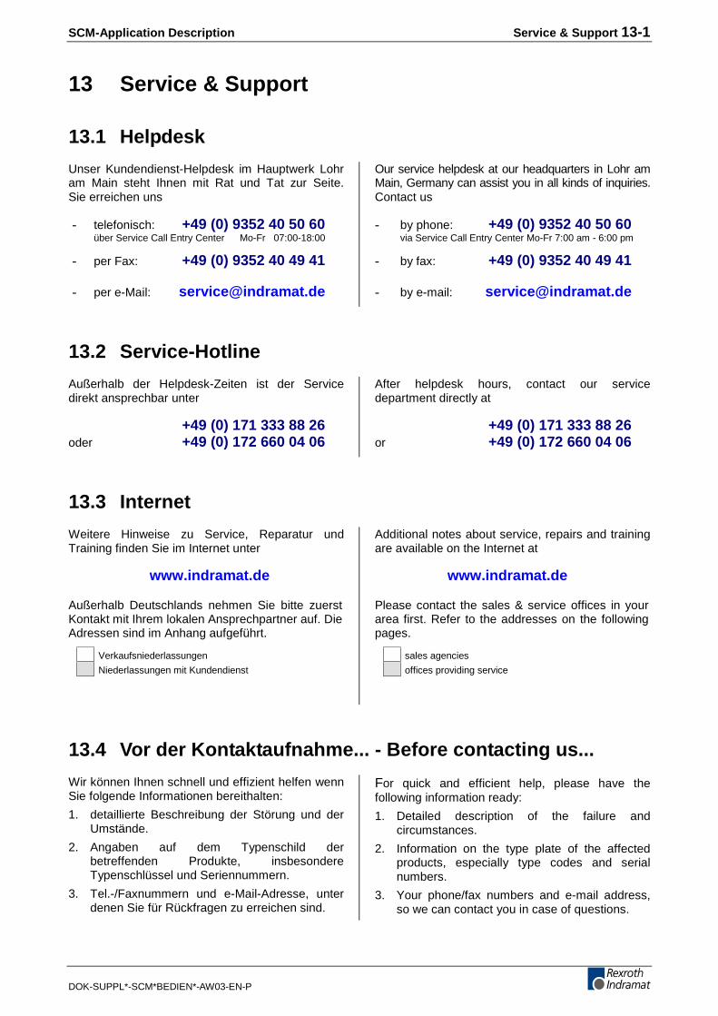
SCM-Application Description Service & Support 13-1
DOK-SUPPL*-SCM*BEDIEN*-AW03-EN-P
13 Service & Support
13.1 Helpdesk
Unser Kundendienst-Helpdesk im Hauptwerk Lohram Main steht Ihnen mit Rat und Tat zur Seite.Sie erreichen uns
- telefonisch: +49 (0) 9352 40 50 60über Service Call Entry Center Mo-Fr 07:00-18:00
- per Fax: +49 (0) 9352 40 49 41
- per e-Mail: [email protected]
Our service helpdesk at our headquarters in Lohr amMain, Germany can assist you in all kinds of inquiries.Contact us
- by phone: +49 (0) 9352 40 50 60via Service Call Entry Center Mo-Fr 7:00 am - 6:00 pm
- by fax: +49 (0) 9352 40 49 41
- by e-mail: [email protected]
13.2 Service-Hotline
Außerhalb der Helpdesk-Zeiten ist der Servicedirekt ansprechbar unter
+49 (0) 171 333 88 26oder +49 (0) 172 660 04 06
After helpdesk hours, contact our servicedepartment directly at
+49 (0) 171 333 88 26or +49 (0) 172 660 04 06
13.3 Internet
Weitere Hinweise zu Service, Reparatur undTraining finden Sie im Internet unter
www.indramat.de
Außerhalb Deutschlands nehmen Sie bitte zuerstKontakt mit Ihrem lokalen Ansprechpartner auf. DieAdressen sind im Anhang aufgeführt.
Verkaufsniederlassungen
Niederlassungen mit Kundendienst
Additional notes about service, repairs and trainingare available on the Internet at
www.indramat.de
Please contact the sales & service offices in yourarea first. Refer to the addresses on the followingpages.
sales agencies
offices providing service
13.4 Vor der Kontaktaufnahme... - Before contacting us...
Wir können Ihnen schnell und effizient helfen wennSie folgende Informationen bereithalten:
1. detaillierte Beschreibung der Störung und derUmstände.
2. Angaben auf dem Typenschild derbetreffenden Produkte, insbesondereTypenschlüssel und Seriennummern.
3. Tel.-/Faxnummern und e-Mail-Adresse, unterdenen Sie für Rückfragen zu erreichen sind.
For quick and efficient help, please have thefollowing information ready:
1. Detailed description of the failure andcircumstances.
2. Information on the type plate of the affectedproducts, especially type codes and serialnumbers.
3. Your phone/fax numbers and e-mail address,so we can contact you in case of questions.

13-2 Service & Support SCM-Application Description
DOK-SUPPL*-SCM*BEDIEN*-AW03-EN-P
13.5 Kundenbetreuungsstellen - Sales & Service Facilities
Deutschland – Germany vom Ausland: (0) nach Landeskennziffer weglassen!from abroad: don’t dial (0) after country code!
Vertriebsgebiet Mitte Germany Centre
Rexroth Indramat GmbHBgm.-Dr.-Nebel-Str. 297816 Lohr am Main
Kompetenz-Zentrum Europa
Tel.: +49 (0)9352 40-0Fax: +49 (0)9352 40-4885
S E R V I C E
C A L L E N T R Y C E N T E RMO – FR
von 07:00 - 18:00 Uhr
from 7 am – 6 pm
Tel. +49 (0) 9352 40 50 [email protected]
S E R V I C E
H O T L IN EMO – FR
von 17:00 - 07:00 Uhrfrom 5 pm - 7 am
+ SA / SO
Tel.: +49 (0)172 660 04 06o d e r / o r
Tel.: +49 (0)171 333 88 26
S E R V I C E
ERSATZTEILE / SPARESverlängerte Ansprechzeit- extended office time -
♦ nur an Werktagen- only on working days -
♦ von 07:00 - 18:00 Uhr- from 7 am - 6 pm -
Tel. +49 (0) 9352 40 42 22
Vertriebsgebiet Süd Germany South
Rexroth Indramat GmbHLandshuter Allee 8-1080637 MünchenTel.: +49 (0)89 127 14-0Fax: +49 (0)89 127 14-490 [email protected]
Gebiet Südwest Germany South-West
Mannesmann Rexroth AGVertrieb Deutschland – VD-BIGeschäftsbereich Rexroth IndramatRegionalzentrum SüdwestRingstrasse 70 / Postfach 114470736 Fellbach / 70701 Fellbach
Tel.: +49 (0)711 57 61–100Fax: +49 (0)711 57 61–125
Vertriebsgebiet Ost Germany East
Rexroth Indramat GmbHBeckerstraße 3109120 Chemnitz
Tel.: +49 (0)371 35 55-0Fax: +49 (0)371 35 55-333
Vertriebsgebiet Nord Germany North
Mannesmann Rexroth AGRegionalzentrum HannoverGesch.ber. Rexroth IndramatWalsroder Str. 9330853 Langenhagen
Tel.: +49 (0) 511 72 66 57-0Fax: +49 (0) 511 72 66 57-95
Vertriebsgebiet West Germany West
Mannesmann Rexroth AGVertrieb DeutschlandRegionalzentrum WestBorsigstrasse 1540880 Ratingen
Tel.: +49 (0)2102 409-0Fax: +49 (0)2102 409-406
Vertriebsgebiet Mitte Germany Centre
Mannesmann Rexroth AGGesch.ber. Rexroth IndramatLilistraße 14-1863067 Offenbach
Tel.: +49 (0) 69 82 00 90-0Fax: +49 (0) 69 82 00 90-80
Vertriebsgebiet Ost Germany East
Mannesmann Rexroth AGGB Rexroth Indramat GmbHHolzhäuser Str. 12204299 Leipzig
Tel.: +49 (0)341 86 77-0Fax: +49 (0)341 86 77-219
Vertriebsgebiet Nord Germany North
Rexroth Indramat GmbHKieler Straße 21222525 Hamburg
Tel.: +49 (0) 40 81 955 966Fax: +49 (0) 40 85 418 978

SCM-Application Description Service & Support 13-3
DOK-SUPPL*-SCM*BEDIEN*-AW03-EN-P
Europa (West) - Europe (West)
vom Ausland: (0) nach Landeskennziffer weglassen, Italien: 0 nach Landeskennziffer mitwählenfrom abroad: don’t dial (0) after country code, Italy: dial 0 after country code
Austria - Österreich
Mannesmann Rexroth GmbHBereich IndramatStachegasse 131120 Wien
Tel.: +43 (0)1 985 2540-0Fax: +43 (0)1 985 2540-93
Austria – Österreich
Mannesmann Rexroth G.m.b.H.Gesch.ber. Rexroth IndramatIndustriepark 184061 Pasching
Tel.: +43 (0)7221 605-0Fax: +43 (0)7221 605-21
Belgium - Belgien
Mannesmann Rexroth N.V.-S.A.Gesch.ber. Rexroth IndramatIndustrielaan 81740 TernatTel.: +32 (0)2 5830719Fax: +32 (0)2 5830731 [email protected]
Denmark - Dänemark
BEC ASZinkvej 68900 Randers
Tel.: +45 (0)87 11 90 60Fax: +45 (0)87 11 90 61
England
Mannesmann Rexroth Ltd.Rexroth Indramat DivisionBroadway Lane, South CerneyCirencester, Glos GL7 5UHTel.: +44 (0)1285 863000Fax: +44 (0)1285 863030 [email protected] [email protected]
Finland - Finnland
Rexroth Mecman OyRexroth Indramat divisionAnsatie 6017 40 VantaaTel.: +358 (0)9 84 91-11Fax: +358 (0)9 84 91-13 60
France - Frankreich
Mannesmann Rexroth S.A.Division Rexroth IndramatAvenue de la TrentaineBP. 7477503 CHELLES CEDEXTel.: +33 (0)164 72-70 00Fax: +33 (0)164 72-63 00Hotline: +33 (0)608 33 43 28
France - Frankreich
Mannesmann Rexroth S.A.Division Rexroth Indramat1270, Avenue de Lardenne31100 ToulouseTel.: +33 (0)5 61 49 95 19Fax: +33 (0)5 61 31 00 41
France - Frankreich
Mannesmann Rexroth S.A.Division Rexroth Indramat91, Bd. Irène Joliot-Curie69634 Vénissieux – CedexTel.: +33 (0)4 78 78 53 65Fax: +33 (0)4 78 78 53 62
Italy - Italien
Mannesmann Rexroth S.p.A.Divisione Rexroth IndramatVia G. Di Vittoria, 120063 Cernusco S/N.MITel.: +39 02 2 365 270Fax: +39 02 700 408 252378
Italy - Italien
Mannesmann Rexroth S.p.A.Divisione Rexroth IndramatVia Borgomanero, 1110145 TorinoTel.: +39 011 7 50 38 11Fax: +39 011 7 71 01 90
Italy - Italien
Mannesmann Rexroth S.p.A.Divisione Rexroth IndramatVia del Progresso, 16 (Zona Ind.)35020 PadovaTel.: +39 049 8 70 13 70Fax: +39 049 8 70 13 77
Italy - Italien
Mannesmann Rexroth S.p.A.Divisione Rexroth IndramatVia Mascia, 180053 Castellamare di Stabia NATel.: +39 081 8 71 57 00Fax: +39 081 8 71 68 85
Italy - Italien
Mannesmann Rexroth S.p.A.Divisione Rexroth IndramatViale Oriani, 38/A40137 BolognaTel.: +39 051 34 14 14Fax: +39 051 34 14 22
Netherlands - Niederlande/Holland
Rexroth B.V.Kruisbroeksestraat 1(P.O. Box 32)5281 RV BoxtelTel.: +31 (0)411 65 19 51Fax: +31 (0)411 65 14 83 [email protected]
Netherlands - Niederlande/Holland
Rexroth Hydrocare B.V.Kruisbroeksestraat 1(P.O. Box 32)5281 RV BoxtelTel.: +31 (0)411 65 19 51Fax: +31 (0)411 67 78 14
Norway - Norwegen
Rexroth Mecman ASRexroth Indramat DivisionBerghagan 1 or: Box 30071405 Ski-Langhus 1402 SkiTel.: +47 (0)64 86 41 00Fax: +47 (0)64 86 90 62 [email protected]
Spain - Spanien
Mannesmann Rexroth S.A.Divisiòn Rexroth IndramatCentro Industrial SantigaObradors s/n08130 Santa Perpetua de MogodaBarcelonaTel.: +34 9 37 47 94 00Fax: +34 9 37 47 94 01
Spain - Spanien
Goimendi S.A.División Rexroth IndramatParque Empresarial ZuatzuC/ Francisco Grandmontagne no.220018 San SebastianTel.: +34 9 43 31 84 21- service: +34 9 43 31 84 56Fax: +34 9 43 31 84 27- service: +34 9 43 31 84 60 [email protected]
Sweden - Schweden
Rexroth Mecman Svenska ABRexroth Indramat DivisionVaruvägen 7125 81 Stockholm
Tel.: +46 (0)8 727 92 00Fax: +46 (0)8 647 32 77
Sweden - Schweden
Rexroth Mecman Svenska ABIndramat SupportEkvändan 7254 67 Helsingborg
Tel.: +46 (0) 42 38 88 -50Fax: +46 (0) 42 38 88 -74
Switzerland West - Schweiz West
Mannesmann Rexroth Suisse SADépartement Rexroth IndramatRue du village 11020 Renens
Tel.: +41 (0)21 632 84 20Fax: +41 (0)21 632 84 21
Switzerland East - Schweiz Ost
Mannesmann Rexroth Schweiz AGGeschäftsbereich IndramatHemrietstrasse 28863 ButtikonTel. +41 (0) 55 46 46 205Fax +41 (0) 55 46 46 222
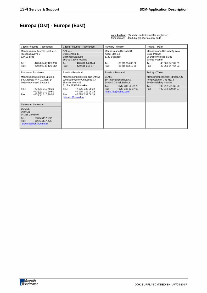
13-4 Service & Support SCM-Application Description
DOK-SUPPL*-SCM*BEDIEN*-AW03-EN-P
Europa (Ost) - Europe (East)
vom Ausland: (0) nach Landeskennziffer weglassen from abroad: don’t dial (0) after country code
Czech Republic - Tschechien
Mannesmann-Rexroth, spol.s.r.o.Hviezdoslavova 5627 00 Brno
Tel.: +420 (0)5 48 126 358Fax: +420 (0)5 48 126 112
Czech Republic - Tschechien
DEL a.s.Strojírenská 38Zdar nad Sázavou591 01 Czech republicTel.: +420 616 64 3144Fax: +420 616 216 57
Hungary - Ungarn
Mannesmann Rexroth Kft.Angol utca 341149 Budapest
Tel.: +36 (1) 364 00 02Fax: +36 (1) 383 19 80
Poland – Polen
Mannesmann Rexroth Sp.zo.o.Biuro Poznanul. Dabrowskiego 81/8560-529 PoznanTel.: +48 061 847 67 99Fax: +48 061 847 64 02
Rumania - Rumänien
Mannesmann Rexroth Sp.zo.o.Str. Drobety nr. 4-10, app. 1470258 Bucuresti, Sector 2
Tel.: +40 (0)1 210 48 25+40 (0)1 210 29 50
Fax: +40 (0)1 210 29 52
Russia - Russland
Mannesmann Rexroth INDRAMATWolokolamskoje Chaussee 73Zimmer 406, 408RUS – 123424 Moskau
Tel.: +7 095/ 232 08 34+7 095/ 232 08 35
Fax: +7 095/ 232 08 36 [email protected]
Russia - Russland
ELMIS10, Internationalnaya Str.246640 Gomel, Belarus
Tel.: +375/ 232 53 42 70Fax: +375/ 232 53 37 69 [email protected]
Turkey - Türkei
Mannesmann Rexroth Hidropar A..S.Fevzi Cakmak Cad No. 334630 Sefaköy Istanbul
Tel.: +90 212 541 60 70Fax: +90 212 599 34 07
Slowenia - Slowenien
DOMELOtoki 2164 228 ZeleznikiTel.: +386 5 5117 152Fax: +386 5 5117 225 [email protected]
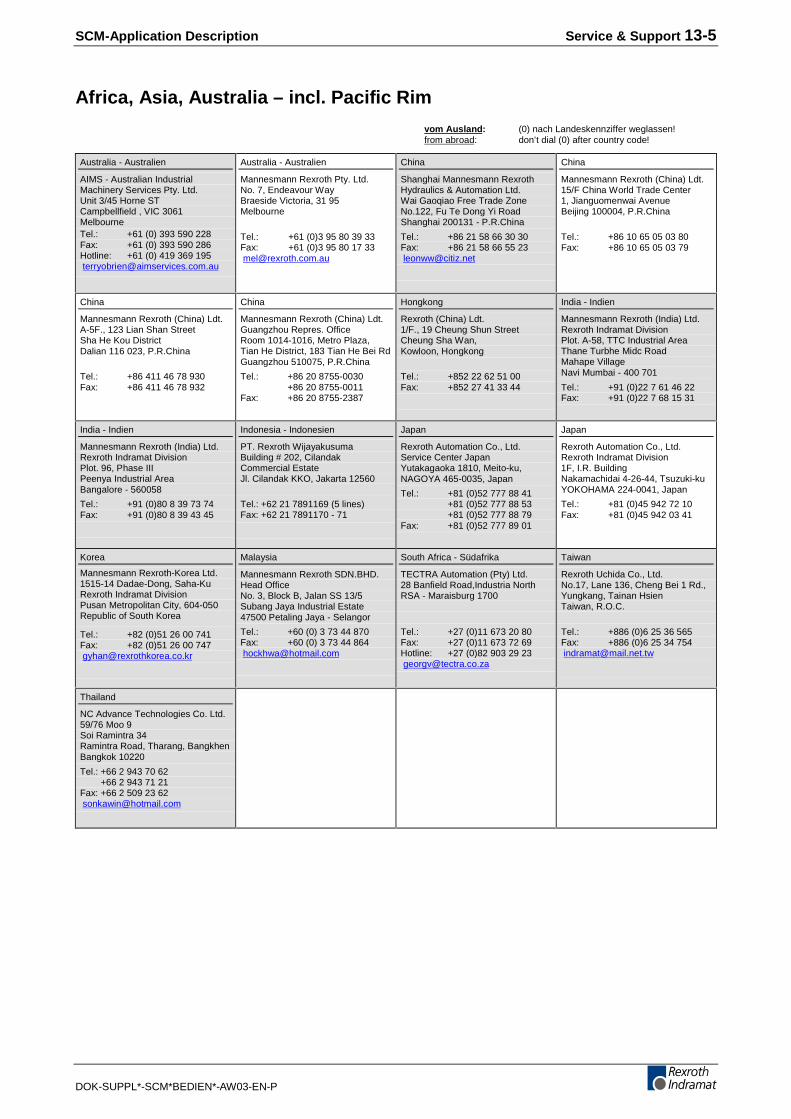
SCM-Application Description Service & Support 13-5
DOK-SUPPL*-SCM*BEDIEN*-AW03-EN-P
Africa, Asia, Australia – incl. Pacific Rim
vom Ausland: (0) nach Landeskennziffer weglassen!from abroad: don’t dial (0) after country code!
Australia - Australien
AIMS - Australian IndustrialMachinery Services Pty. Ltd.Unit 3/45 Horne STCampbellfield , VIC 3061MelbourneTel.: +61 (0) 393 590 228Fax: +61 (0) 393 590 286Hotline: +61 (0) 419 369 195 [email protected]
Australia - Australien
Mannesmann Rexroth Pty. Ltd.No. 7, Endeavour WayBraeside Victoria, 31 95Melbourne
Tel.: +61 (0)3 95 80 39 33Fax: +61 (0)3 95 80 17 33 [email protected]
China
Shanghai Mannesmann RexrothHydraulics & Automation Ltd.Wai Gaoqiao Free Trade ZoneNo.122, Fu Te Dong Yi RoadShanghai 200131 - P.R.China
Tel.: +86 21 58 66 30 30Fax: +86 21 58 66 55 23 [email protected]
China
Mannesmann Rexroth (China) Ldt.15/F China World Trade Center1, Jianguomenwai AvenueBeijing 100004, P.R.China
Tel.: +86 10 65 05 03 80Fax: +86 10 65 05 03 79
China
Mannesmann Rexroth (China) Ldt.A-5F., 123 Lian Shan StreetSha He Kou DistrictDalian 116 023, P.R.China
Tel.: +86 411 46 78 930Fax: +86 411 46 78 932
China
Mannesmann Rexroth (China) Ldt.Guangzhou Repres. OfficeRoom 1014-1016, Metro Plaza,Tian He District, 183 Tian He Bei RdGuangzhou 510075, P.R.China
Tel.: +86 20 8755-0030+86 20 8755-0011
Fax: +86 20 8755-2387
Hongkong
Rexroth (China) Ldt.1/F., 19 Cheung Shun StreetCheung Sha Wan,Kowloon, Hongkong
Tel.: +852 22 62 51 00Fax: +852 27 41 33 44
India - Indien
Mannesmann Rexroth (India) Ltd.Rexroth Indramat DivisionPlot. A-58, TTC Industrial AreaThane Turbhe Midc RoadMahape VillageNavi Mumbai - 400 701
Tel.: +91 (0)22 7 61 46 22Fax: +91 (0)22 7 68 15 31
India - Indien
Mannesmann Rexroth (India) Ltd.Rexroth Indramat DivisionPlot. 96, Phase IIIPeenya Industrial AreaBangalore - 560058
Tel.: +91 (0)80 8 39 73 74Fax: +91 (0)80 8 39 43 45
Indonesia - Indonesien
PT. Rexroth WijayakusumaBuilding # 202, CilandakCommercial EstateJl. Cilandak KKO, Jakarta 12560
Tel.: +62 21 7891169 (5 lines)Fax: +62 21 7891170 - 71
Japan
Rexroth Automation Co., Ltd.Service Center JapanYutakagaoka 1810, Meito-ku,NAGOYA 465-0035, Japan
Tel.: +81 (0)52 777 88 41+81 (0)52 777 88 53+81 (0)52 777 88 79
Fax: +81 (0)52 777 89 01
Japan
Rexroth Automation Co., Ltd.Rexroth Indramat Division1F, I.R. BuildingNakamachidai 4-26-44, Tsuzuki-kuYOKOHAMA 224-0041, Japan
Tel.: +81 (0)45 942 72 10Fax: +81 (0)45 942 03 41
Korea
Mannesmann Rexroth-Korea Ltd.1515-14 Dadae-Dong, Saha-KuRexroth Indramat DivisionPusan Metropolitan City, 604-050Republic of South Korea
Tel.: +82 (0)51 26 00 741Fax: +82 (0)51 26 00 747 [email protected]
Malaysia
Mannesmann Rexroth SDN.BHD.Head OfficeNo. 3, Block B, Jalan SS 13/5Subang Jaya Industrial Estate47500 Petaling Jaya - Selangor
Tel.: +60 (0) 3 73 44 870Fax: +60 (0) 3 73 44 864 [email protected]
South Africa - Südafrika
TECTRA Automation (Pty) Ltd.28 Banfield Road,Industria NorthRSA - Maraisburg 1700
Tel.: +27 (0)11 673 20 80Fax: +27 (0)11 673 72 69Hotline: +27 (0)82 903 29 23 [email protected]
Taiwan
Rexroth Uchida Co., Ltd.No.17, Lane 136, Cheng Bei 1 Rd.,Yungkang, Tainan HsienTaiwan, R.O.C.
Tel.: +886 (0)6 25 36 565Fax: +886 (0)6 25 34 754 [email protected]
Thailand
NC Advance Technologies Co. Ltd.59/76 Moo 9Soi Ramintra 34Ramintra Road, Tharang, BangkhenBangkok 10220
Tel.: +66 2 943 70 62 +66 2 943 71 21Fax: +66 2 509 23 62 [email protected]
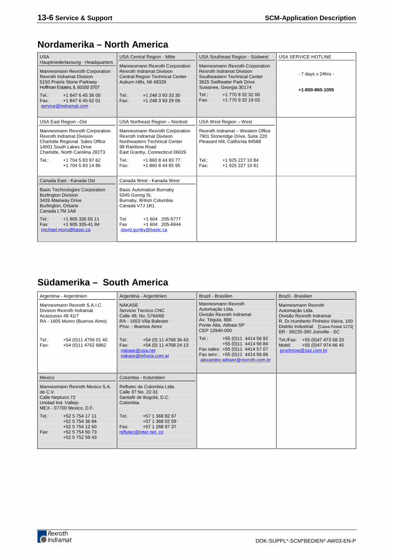
13-6 Service & Support SCM-Application Description
DOK-SUPPL*-SCM*BEDIEN*-AW03-EN-P
Nordamerika – North AmericaUSAHauptniederlassung - Headquarters
Mannesmann Rexroth CorporationRexroth Indramat Division5150 Prairie Stone ParkwayHoffman Estates, IL 60192-3707
Tel.: +1 847 6 45 36 00Fax: +1 847 6 45 62 01 [email protected]
USA Central Region - Mitte
Mannesmann Rexroth CorporationRexroth Indramat DivisionCentral Region Technical CenterAuburn Hills, MI 48326
Tel.: +1 248 3 93 33 30Fax: +1 248 3 93 29 06
USA Southeast Region - Südwest
Mannesmann Rexroth CorporationRexroth Indramat DivisionSoutheastern Technical Center3625 Swiftwater Park DriveSuwanee, Georgia 30174
Tel.: +1 770 9 32 32 00Fax: +1 770 9 32 19 03
USA SERVICE-HOTLINE
- 7 days x 24hrs -
+1-800-860-1055
USA East Region –Ost
Mannesmann Rexroth CorporationRexroth Indramat DivisionCharlotte Regional Sales Office14001 South Lakes DriveCharlotte, North Carolina 28273
Tel.: +1 704 5 83 97 62+1 704 5 83 14 86
USA Northeast Region – Nordost
Mannesmann Rexroth CorporationRexroth Indramat DivisionNortheastern Technical Center99 Rainbow RoadEast Granby, Connecticut 06026
Tel.: +1 860 8 44 83 77Fax: +1 860 8 44 85 95
USA West Region – West
Rexroth Indramat – Western Office7901 Stoneridge Drive, Suite 220Pleasant Hill, California 94588
Tel.: +1 925 227 10 84Fax: +1 925 227 10 81
Canada East - Kanada Ost
Basic Technologies CorporationBurlington Division3426 Mainway DriveBurlington, OntarioCanada L7M 1A8
Tel.: +1 905 335 55 11Fax: +1 905 335-41 84 [email protected]
Canada West - Kanada West
Basic Automation Burnaby5345 Goring St.Burnaby, British ColumbiaCanada V7J 1R1
Tel. +1 604 205-5777Fax +1 604 205-6944 [email protected]
Südamerika – South AmericaArgentina - Argentinien
Mannesmann Rexroth S.A.I.C.Division Rexroth IndramatAcassusso 48 41/7RA - 1605 Munro (Buenos Aires)
Tel.: +54 (0)11 4756 01 40Fax: +54 (0)11 4762 6862
Argentina - Argentinien
NAKASEServicio Tecnico CNCCalle 49, No. 5764/66RA - 1653 Villa BalesterProv. - Buenos Aires
Tel.: +54 (0) 11 4768 36 43Fax: +54 (0) 11 4768 24 13 [email protected] [email protected]
Brazil - Brasilien
Mannesmann RexrothAutomação Ltda.Divisão Rexroth IndramatAv. Tégula, 888Ponte Alta, Atibaia SPCEP 12940-000
Tel.: +55 (0)11 4414 56 92 +55 (0)11 4414 56 84
Fax sales: +55 (0)11 4414 57 07Fax serv.: +55 (0)11 4414 56 86 [email protected]
Brazil - Brasilien
Mannesmann RexrothAutomação Ltda.Divisão Rexroth IndramatR. Dr.Humberto Pinheiro Vieira, 100Distrito Industrial [Caixa Postal 1273]BR - 89220-390 Joinville - SC
Tel./Fax: +55 (0)47 473 58 33Mobil: +55 (0)47 974 66 45 [email protected]
Mexico
Mannesmann Rexroth Mexico S.A.de C.V.Calle Neptuno 72Unidad Ind. VallejoMEX - 07700 Mexico, D.F.
Tel.: +52 5 754 17 11+52 5 754 36 84+52 5 754 12 60
Fax: +52 5 754 50 73+52 5 752 59 43
Columbia - Kolumbien
Reflutec de Colombia Ltda.Calle 37 No. 22-31Santafé de Bogotá, D.C.Colombia
Tel.: +57 1 368 82 67+57 1 368 02 59
Fax: +57 1 268 97 [email protected]. co


Prin
ted
in G
erm
any
2 8 5 6 3 6