screw jack calculations
TRANSCRIPT

7/23/2019 Screw Jack Calculations
http://slidepdf.com/reader/full/screw-jack-calculations 1/6
169
C r i t i c a l b u c k l i n g f o r c e F i n k N
k
free length L in mm
Selection, Calculation, Checklists
Critical Buckling Force of the Lifting Screws
Maximum allowed axial load
F = 0.8 x F x f all k k
F maximum allowable axial load (kN)all
F theoretical critical buckling forcek
(kN) acc. to diagramf correction value (considers kind of k
bearing support, respectively guidance of lifting load) see pictograms above
f = 4k
Version Rfor a small L1 there applies: fk = 2guided lifting motion
f = 2k
Version Sguided lifting motion,gear firmly mounted
f = 0,25k
Version Snon guided lifting motion,gear firmly mounted
f = 1k
Version Sguided lifting motion withhinged plate
If the maximum calculated load is lower thanrequired, a larger spindle diameter couldbe selected. The calculations must thenbe reworked.With the rotating screw version a larger diameter screw can be selected (from thenext bigger gearbox size). Any increase in pitch/ lifting speed mustbe taken into account.The safety factors for the type of systemspecified must be used, as shown above,
to calculate the max allowable axial loadfor the system.
There is a buckling risk especially
with gearboxes with long, thinspindles in combination withcompression load. With thefollowing calculation you can findthe max. allowed axial load acc.to Euler.

7/23/2019 Screw Jack Calculations
http://slidepdf.com/reader/full/screw-jack-calculations 2/6
170
Selection, Calculation, Checklists
Critical Whirling Speed of Spindle - R Version
Maximum allowablespindle speed
n = 0.8 x n x f all kr kr
For R version gearboxes (with rotatingspindle) with long, thin spindles it isnecessary to calculate the maximum allowablespindle speed. Please take the theoreticalcritical speed n from the diagram. Alsokr
consider the additional lengths for spindlecovers, etc. when calculating the unsupportedscrew lengths .Together with the correction factor for the bearing layout the max. allowablespindle speed can be calculated.
f = 1kr
with opposedbearing plate
f = 0.5kr
without opposed
bearing plate
unsupported screw lengths [m]
- 1
t h e o r e t i c a l s p i n d l e w h i r l i n g s p e e d n
[ m i n
]
k r
If the calculated maximum spindle speed islower than that required, a larger spindleshould be selected. The calculations mustthen be reworked.If a larger diameter spindle is used in theR version the potential for higher drivetorque's must be considered.The safety factors for the type of systemspecified must be used, as shown above,to calculate the maximum allowable axial loadfor the system.
spindle speed =input speed
igearbox. . . . .
7/23/2019 Screw Jack Calculations
http://slidepdf.com/reader/full/screw-jack-calculations 3/6
171
Selection, Calculation, Checklists
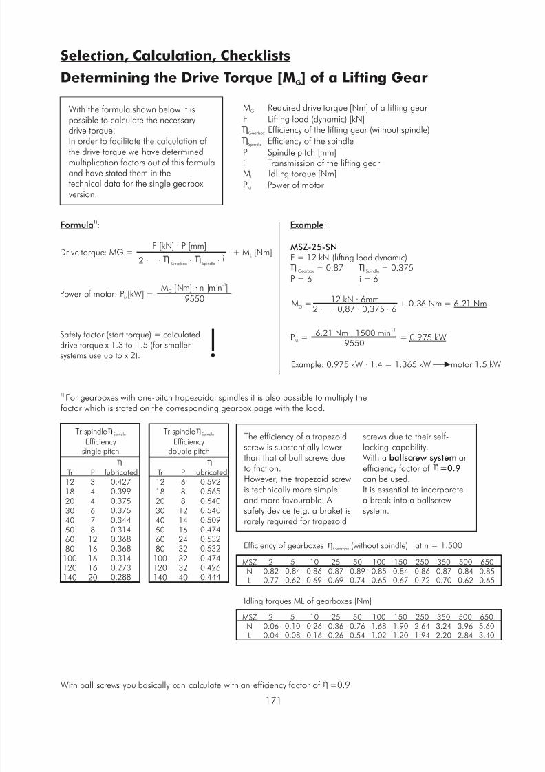
Determining the Drive Torque [M ] of a Lifting GearG
With the formula shown below it ispossible to calculate the necessary
drive torque.In order to facilitate the calculation of the drive torque we have determinedmultiplication factors out of this formulaand have stated them in thetechnical data for the single gearboxversion.
M Required drive torque [Nm] of a lifting gear G
F Lifting load (dynamic) [kN] Efficiency of the lifting gear (without spindle)
Gearbox Efficiency of the spindleSpindle
P Spindle pitch [mm]i Transmission of the lifting gear M Idling torque [Nm]L
P Power of motor M
1)Formula :
Drive torque: MG = + M [Nm]L
F [kN] · P [mm]
i2 · · · ·Gearbox Spindle
Power of motor: P [kW] =M
-1M [Nm] · n [min ]G
9550
Safety factor (start torque) = calculateddrive torque x 1.3 to 1.5 (for smaller systems use up to x 2). !1) For gearboxes with one-pitch trapezoidal spindles it is also possible to multiply the
factor which is stated on the corresponding gearbox page with the load.
Example:
MSZ-25-SNF = 12 kN (lifting load dynamic)
= 0.87 = 0.375Gearbox Spindle
P = 6 i = 6
M = + 0.36 Nm = 6.21 NmG
12 kN · 6mm2 · · 0,87 · 0,375 · 6
Example: 0.975 kW · 1.4 = 1.365 kW motor 1.5 kW
P = = 0.975 kWM
-16.21 Nm · 1500 min
9550
Tr spindle Spindle
Efficiencysingle pitch
Tr 121820304050
6080100120140
P344678
1216161620
lubricated0.4270.3990.3750.3750.3440.314
0.3680.3680.3140.2730.288
Tr 121820304050
6080
100120140
P688121416
2432323240
lubricated0.5920.5650.5400.5400.5090.474
0.5320.5320.4740.4260.444
Tr spindle Spindle
Efficiencydouble pitch
The efficiency of a trapezoidscrew is substantially lowerthan that of ball screws dueto friction.However, the trapezoid screwis technically more simpleand more favourable. Asafety device (e.g. a brake) israrely required for trapezoid
screws due to their self-locking capability.With a ballscrew system anefficiency factor of =0.9 can be used.It is essential to incorporatea break into a ballscrewsystem.
Efficiency of gearboxes (without spindle) at n = 1.500Gearbox
MSZNL
20.820.77
50.840.62
100.860.69
250.870.69
500.890.74
1000.850.65
1500.840.67
2500.860.72
3500.870.70
5000.840.62
6500.850.65
MSZNL
20.060.04
50.100.08
100.260.16
250.360.26
500.760.54
1001.681.02
1501.901.20
2502.641.94
3503.242.20
5003.962.84
6505.603.40
Idling torques ML of gearboxes [Nm]
With ball screws you basically can calculate with an efficiency factor of =0.9

7/23/2019 Screw Jack Calculations
http://slidepdf.com/reader/full/screw-jack-calculations 4/6
172
Selection, Calculation, Checklists
Drive Torque for Gearboxes
Calculation
The required drive torque of alifting gear results from the sum ofthe moments of the individuallifting units. This is increased due tofrictional losses of transmissioncomponents like couplings,
connecting shafts, bevel gears, etc.To simplify the calculation, somefactors for determining the drivetorque in the most commonapplications are provided below.
M = M x 2.25R G
M = M x 2.1R G M = M x 3.1R G M = M x 3.35R G
M = M x 4.6R G M = M x 6.8R G M = M x 4.4R G
M = M x 3.34R G M = M x 3.27R G
M - Total drive torque for theR
whole system
M - Input torque of a single gearboxG
M - Starting torque max. 1.5 x M A R
Attention:
It is recommended to multiply thecalculated value with a safetyfactor of 1.3 to 1.5 (for smallersystems factor up to 2). Theindicated values are applicable incases of uniform distribution of thelifting gear load onto all gears!
Example (example from previous page, 12 kN per gearbox)
M = M x 4.6 = 6.21 Nm x 4.6 = 28.57 NmR G
x safety factor 1.3 = 37.14Nm

7/23/2019 Screw Jack Calculations
http://slidepdf.com/reader/full/screw-jack-calculations 5/6
173
Selection, Calculation, Checklists
Maximum Power / Moments
Load definitions
F - Lifting load tension and/or compressionF - Side forces on the spindleS
v - Lifting speed of the spindleH
(or nut of the R version)F - Axial load of the input shaft A
F - Radial load of the input shaftR
M - Drive torqueR
n - Drive speedR
Please examine the information on the following pages before makingyour choice of the lifting gear suited for your application. Variousinfluences and assumptions can only be estimated on the basis of
information gained by experience. In case of doubt please contact T.E.A.
F
Side forces on the spindlePlease refer to the adjoiningtable for the maximumpermissible side force. Sideforces should be supported bya guidance system wheneverpossible. The bronze bushingsin the gearbox are a
secondary support only andshould not be relied upon asadequate guidance. Themaximum side force at agiven screw extension mustnot exceed that stated in theadjoining table. Attention:only statically allowed!
Max. drive torqueThe stated values of the tableon the right should not beexceeded. If gearboxes arearranged in tandem or in
larger arrangements themaximum drive torque maybe higher. If there are morethan 5 gearboxes in anarrangement please contactT.E.A.
Radial load on the inputshaftThe radial forces of the tableon the right should not beexceeded if you use chaindrives or belt drives.
FS
V H
lifting screw
MRnR
F A
FR
input shaft
= worm shaft
MSZ5102550
100150250350
500650750
Type
M SN/RNR
M SN/RNR
M SL/RLR
M SL/RLR
min-1
15005001500
500
SHZ-020.71.00.5
0.7
MSZ-5
6.410.42.6
4.3
MSZ-10
12.620.55.3
8.4
MSZ-25
21.734.27.8
12.5
MSZ-50
44.770.315.5
24.5
MSZ-10072.0114.917.0
27.8
MSZ-15067.3107.017.3
27.7
MSZ-250
118.4185.123.5
36.6
MSZ-350
187.0295.740.2
63.9
MSZ-500
204.3325.642.8
71.2
MSZ-650
268.3427.962.8
102.6
MSZ-750
415.0663.083.0
132.0
1003606009003000500055009000
15000
290003480046000
200160280470
200040005000900013000
290003480046000
300100180300
130030003900650012000
290003480039000
40070
130240900230028004900
10000
290003480036000
50055100180700
1800230038008800
290003480032000
6004580
150600
1500180030007000
240002880030000
7003870
1305001300150025006000
200002400025000
8003260110420
1100130022005500
170002040029000
9002850
100380950120020004800
150001800025000
1000254790
330850100019004300
140001680023500
1200204070280700850
14503500
120001440020000
1500183060
23060075012503000
90001080017000
2000122045
1604005009002000
7000840012000
2500–
1535130350400760
1600
5600672010000
3000––
30100250350660
1400
490058808000
F max.R
SHZ-0218
MSZ-5110
MSZ-10215
MSZ-25300
MSZ-50520
MSZ-100800
MSZ-150810
MSZ-2501420
MSZ-3502100
MSZ-5003780
MSZ-6504536
- Consider that the starting torque is factor 1.5 of the operation torque- Limit values are mechanical - consider thermical factors depending on operating time
Maximum side force F [N] (static) extended screw length in mmS
Maximum drive torque M [Nm]R
Maximum radial load acting on the input shaft F [N]R

7/23/2019 Screw Jack Calculations
http://slidepdf.com/reader/full/screw-jack-calculations 6/6
Your partner in quality engineering products since 1986
Thank you for viewing product information on TEA’s range of engineering components.
Now please contact us at the nearest office to you for any further information, prices and availability:
AUSTRALIA & New Zealand USA, South America & Canada
T E A Transmissions Pty Ltd T E A Machine Components Inc
Tahiti Road 2281-F Dabney Road
Tiaro Qld 4650 Richmond Virginia 23230
Australia USA
Ph: 61-(0)7 4129 2533 Ph: 1-804-342-0004
Fax: 61-(0)7 4129 2437 Fax: 1-804-342-0006
Email: [email protected] Email: [email protected]
www.tea.net.au www.teausa.net
You are assured of prompt and efficient service at all time