sd 18 - 3/03 - simafroid of contents page indice pag table des matieres page inhalt seite general...
TRANSCRIPT

SERVICE MANUAL - MANUALE DI SERVIZIOMANUEL DE SERVICE - BEDIENUNGSANLEITUNG
SD 18R 134a
Ice cubers
Fabbricatoridi ghiaccio a cubetti
Machines á glaçons
Kegeleisbereiter
REV. 03/2004
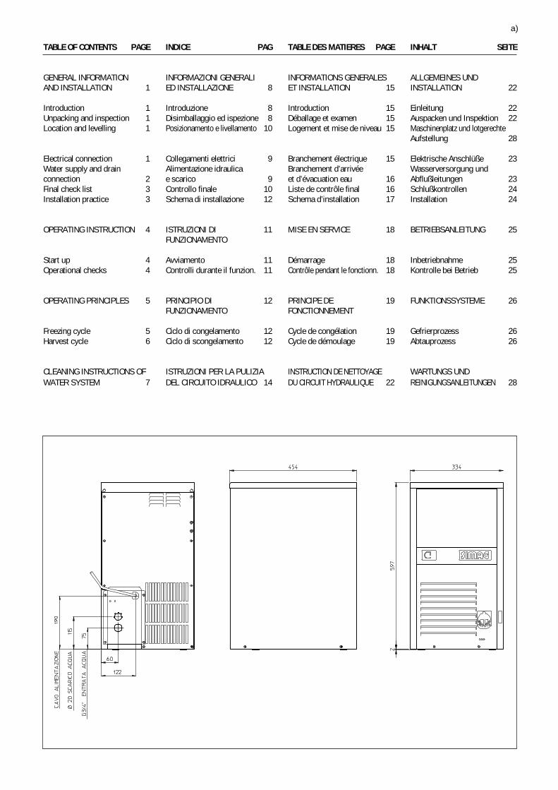
TABLE OF CONTENTS PAGE INDICE PAG TABLE DES MATIERES PAGE INHALT SEITE
GENERAL INFORMATION INFORMAZIONI GENERALI INFORMATIONS GENERALES ALLGEMEINES UNDAND INSTALLATION 1 ED INSTALLAZIONE 8 ET INSTALLATION 15 INSTALLATION 22
Introduction 1 Introduzione 8 Introduction 15 Einleitung 22Unpacking and inspection 1 Disimballaggio ed ispezione 8 Déballage et examen 15 Auspacken und Inspektion 22Location and levelling 1 Posizionamento e livellamento 10 Logement et mise de niveau 15 Maschinenplatz und lotgerechte
Aufstellung 28
Electrical connection 1 Collegamenti elettrici 9 Branchement électrique 15 Elektrische Anschlüße 23Water supply and drain Alimentazione idraulica Branchement d’arrivée Wasserversorgung undconnection 2 e scarico 9 et d’évacuation eau 16 Abflußleitungen 23Final check list 3 Controllo finale 10 Liste de contrôle final 16 Schlußkontrollen 24Installation practice 3 Schema di installazione 12 Schema d’installation 17 Installation 24
OPERATING INSTRUCTION 4 ISTRUZIONI DI 11 MISE EN SERVICE 18 BETRIEBSANLEITUNG 25FUNZIONAMENTO
Start up 4 Avviamento 11 Démarrage 18 Inbetriebnahme 25Operational checks 4 Controlli durante il funzion. 11 Contrôle pendant le fonctionn. 18 Kontrolle bei Betrieb 25
OPERATING PRINCIPLES 5 PRINCIPIO DI 12 PRINCIPE DE 19 FUNKTIONSSYSTEME 26FUNZIONAMENTO FONCTIONNEMENT
Freezing cycle 5 Ciclo di congelamento 12 Cycle de congélation 19 Gefrierprozess 26Harvest cycle 6 Ciclo di scongelamento 12 Cycle de démoulage 19 Abtauprozess 26
CLEANING INSTRUCTIONS OF ISTRUZIONI PER LA PULIZIA INSTRUCTION DE NETTOYAGE WARTUNGS UNDWATER SYSTEM 7 DEL CIRCUITO IDRAULICO 14 DU CIRCUIT HYDRAULIQUE 22 REINIGUNGSANLEITUNGEN 28
a)
b)

TECHNICAL SPECIFICATIONS - SPECIFICHE TECNICHE - DONNÉES TECHNIQUE - TECHNISCHE ANGABEN
SD 18 SD 18 WElectric voltageAlimentazione elettrica 230/50/1 230/50/1Alimentation électrique -10 ÷ +10% -10 ÷ +10%Normale Netzspannung
Condensation Air WaterCondensazione Aria AcquaCondensation Air EauKühlung Luft Wasser
Bin capacity (kg)Capacità contenitore (kg)Capacité bac glaçons (kg) 6,5 6,5Speicher Kapazität (kg)
Net weight (kg)Peso netto (kg)Poids net (kg) 28 28Netto Gewicht (kg)
Cubes per cycleCubetti per cicloGlaçons par cycle 15 15Würfel per Fase
Compressor power HPPotenza compressore CVPuissance compresseur CV 1/6 1/6Kompressorleistung PS
Running ampsAmperaggio di marciaAmpérage en marche 1,2 1,2Ampere
Start ampsAmperaggio d’avv.Ampérage de démarr. 6,7 6,7Start Ampere
Power (Watts)Potenza (Watt)Puissance (Watts) 340 340Leistung (Watt)
Power cons. in 24 hrs (Kwh)Consumo elettr. in 24 ore (Kwh)Cons. electr. en 24 hrs (Kwh) 7 7Stromverbrauch in 24 Std. (kWh)
Wire size (mm )Sezione cavi (mm )Section fils (mm ) 3 x 1 3 x 1Kabelanzahl (mm )
Water consumption (lt/hr)Consumo acqua (lt/ora)Consommation eau (lt/hr) 5 12,5Wasserverbrauch (lt/std)
Refrig. charge R 134 A (gr)Carica refrig. R 134 A (gr)Charge refrig. R 134 A (gr) 210 190Kühlmittel - Füll. R 134 A (gr)
Refrigerant metering device Capillary tube Capillary tubeDisp. espansione refrigerante Tubo capillare Tubo capillareDétente du Rèfrigérant Tube Capillaire Tube CapillaireKältemittel - Expansionssystem Kapillarrohr Kapillarrohr
Water - Acqua - Eau - Wasser: 15°C (60°F)Envir. - Amb. - Amb. - Raum: 21°C (84°F)
2
2
22
c)
OPERATING PRESSURES - PRESSIONI DI FUNZIONAMENTO - PRESSIONES DE FONCTIONNEMENT - BETRIEBSDRÜCKE
Discharge pressure - Pressione di mandata Suction pressure - Pressione di aspirazioneHaute pression - Hochdruckbereich Basse pression - Niederdrück
Freezing cycle - Ciclo di congelamento End of freezing cycle - Fine ciclo di congelamentoCycle de Congélation - Gefrierfase Fin du cycle de congélation - Ende der Gefrierfase
Air cooled - Raffr. ad aria 6 ÷ 129 bar 0,7 ÷ 0.9 barRefroid. à air - Luftgekühlt 90 ÷ 175 psig 10 ÷ 13 psig
Water cooled - Raffr. ad acqua 9.5 ÷ 10.5 bar 0,7 ÷ 0.9 barRefroid. à eau - Wassergekühlt 140 ÷ 150 psig 10 ÷ 13 psig
SD 18 A
SD 18 W

WIRING DIAGRAM - SCHEMA ELETTRICO - SCHÉMA ÉLECTRIQUE - SCHALTUNGSSCHEMA
AIR & WATER COOLED - RAFFREDDAMENTO AD ARIA ED AD ACQUAREFROIDISSEMENT PAR AIR ET PAR EAU - LUFT UND WASSERGEKÜHLT
d)
BNAM
GV
- WHITE - BIANCO - BLANC - WEIB- BLACK - NERO - NOIR - SCHWARZ- BLUE - BLU - BLEU - BLAU- BROWN - MARRONE - MARRON - BRAUN- YELLOW GREEN - GIALLO VERDE JAUNE VERT - GELB GRUEN

e)
Capacità di produzione - Ice making capacity - Capacité de production - Eisproduktionskapazität
20
19
18
17
16
15
14
13
12
11
10
9
K g .
RAFFREDDAMENTO AD ARIA - AIR COOLED MODELSCONDENSATION PAR AIR - LUFTKÜHLUNG
TEMPERATURA ACQUA - WATER TEMPERATURETEMPÉRATURE DE L'EAU - WASSERTEMPERATUR
TEM
PERA
TURA
AM
BIEN
TE -
AMBI
ENT
TEM
PERA
TURE
TEM
PÉRA
TURE
AM
BIAN
T - R
AUM
TEM
PERA
TUR
PROD
UZIO
NE G
HIAC
CIO
(KG
PER
24 O
RE) -
ICE
PROD
UCED
(KG.
PER
24
HRS)
PROD
UCTI
ON D
E GL
ACE
(KG.
PAR
24 H
EURE
S) -
EISW
ÜRFE
LPRO
DUKT
ION
(KG.
IN 2
4 ST
D.)
°C
10
20
30
35
25 20 15 10 °C
20
19
18
17
16
15
14
13
12
11
10
9
K g .
RAFFREDDAMENTO AD ACQUA - WATER COOLED MODELSCONDENSATION PAR EAU - WASSERKÜHLUNG
TEMPERATURA ACQUA - WATER TEMPERATURETEMPÉRATURE DE L'EAU - WASSERTEMPERATUR
TEM
PERA
TURA
AM
BIEN
TE -
AMBI
ENT
TEM
PERA
TURE
TEM
PÉRA
TURE
AM
BIAN
T - R
AUM
TEM
PERA
TUR
PROD
UZIO
NE G
HIAC
CIO
(KG
PER
24 O
RE) -
ICE
PROD
UCED
(KG.
PER
24
HRS)
PROD
UCTI
ON D
E GL
ACE
(KG.
PAR
24 H
EURE
S) -
EISW
ÜRFE
LPRO
DUKT
ION
(KG.
IN 2
4 ST
D.)
°C10
20
30
35
25 20 15 10 °C

8. Remove the manufacturer’s registrationcard from the inside of the User Manual and fill-in all parts including: Model and Serial Numbertaken from the data plate.Forward the completed self-addressedregistration card to the factory.
C. LOCATION AND LEVELLING
WARNING. This Ice Cuber is designed forindoor installation only. Extended periodsof operation at temperatures exceedingthe following limitations will constitutemisuse under the terms of theManufacturer’s Limited Warrantyresulting in LOSS of warranty coverage.
1. Position the unit in the selected permanentlocation.Criteria for selection of location include:
a) Minimum room temperature 10°C andmaximum room temperature 35°C.
b) Water inlet temperatures: minimum 5°Cand maximum 40°C.
c) Well ventilated location for air cooledmodels. Clean the air cooled condenser atfrequent intervals.
d) Service access: adequate space mustbe left for all service connections through therear of the ice maker. A minimum clearance of 15cm (6") must be left at the sides of the unit forrouting cooling air drawn into and exhausted outof the compartment to maintain propercondensing operation of air cooled models.
NOTE. With the unit in “built-in” conditions,the ice production is gradually reduced inrespect to the levels shown in the graph.
The daily ice-making capacity is directlyrelated to the condenser air inlet temperatu-re, water temperature and age of the machine.
To keep your CUBER at peak performancelevels, periodic maintenance checks mustbe carried out as indicated on CleaningSection of this manual.
2. Level the unit in both the left to right andfront to rear directions.
D. ELECTRICAL CONNECTIONS
See data plate for current requirements todetermine wire size to be used on electricalconnections. All icemakers require a solid earthwire.
GENERAL INFORMATIONAND INSTALLATION
A. INTRODUCTION
These Cubers are quality designed, engineeredand manufactured.Their ice making systems are thoroughly testedproviding the utmost in flexibility to fit the needsof a particular user.These icemakers have been engineered to ourown rigid safety and performence standards.
NOTE. To retain the safety and performancebuilt into this icemaker, it is important thatinstallation and maintenance be conductedin the manner outlined in this manual.
B. UNPACKING AND INSPECTION
1. Visually inspect the exterior of the packingand skid. Any severe damage noted should bereported to the delivering carrier and a concealeddamage claim form filled in subjet to inspection ofthe contents with the carrier’s representativepresent.
2. a) Cut and remove the plastic strip securingthe carton box to the skid.
b) Cut open the top of the carton and removethe polystyre protection sheet.
c) Pull out the polystyre posts from thecorners and then remove the carton.
3. Remove the front and the rear panels of theunit and inspect for any concealed damage.Notify carrier of your claim for the concealeddamage as steted in step 1 above.
4. Remove all internal support packing andmasking tape.
5. Check that refrigerant lines do not rubagainst or touch other lines or surfaces, and thatthe fan blade moves freely.
6. Use clean damp cloth to wipe the surfacesinside the storage bin and the outside of thecabinet.
7. See data plate on the rear side of the unitand check that local main voltage correspondswith the voltage specified on it.
CAUTION. Incorrect voltage supplied tothe icemaker will void your partsreplacement program.
Page 1

The ice machines are supplied from the factorycompletely pre-wired and require only electricalpower connections to wire cord provided on theback of the unit.Make sure that the ice machine is connected toits own circuit and individually fused (see dataplate for fuse size).The maximum allowable voltage variation shouldnot exceed -10% and +10% of the data platerating. Low voltage can cause faulty functioningand may be responsible for serious damage tothe overload switch and motor windings.
NOTE. All external wiring should conform tonational, state and local standards andregulations.Check voltage on the line and the ice maker’sdata plate before connecting the unit.
E. WATER SUPPLY AND DRAINCONNECTIONS
General
When choosing the water supply for the ice cuberconsideration should be given to:
a) Length of run
b) Water clarity and purity
c) Adequate water supply pressure
Since water is the most important single ingredientin producting ice you cannot emphasize toomuch the three items listed above.Low water pressure, below 1 bar may causemalfunction of the ice maker unit.Water containing excessive minerals will tend toproduce cloudy coloured ice cubes, plus scalebuilt-up on parts of the water system.
Water supply
Connect the 3/4" male fitting of the solenoidwater inlet valve, using the flexible tubing supplied,to the cold water supply line with regular plumbingfitting and a shut-off valve installed in anaccessible position between the water supplyline and the unit.
Water drain
The recommended drain tube is a plastic orflexible tube with 18 mm (3/4") I.D. runs to anopen trapped and vented drain. When the drainis a long run, allow 3 cm pitch per meter (1/4"pitch per foot).On water cooled versions, the water drain linefrom the condenser is internally connected withthe drain fitting of the unit.A vertical open vent, at the unit drain connection,is also required for proper sump drainage.
NOTE. The water supply and the water drainmust be installed to conform with the localcode. In some case a licensed plumber and/or a plumbing permit is required.
Page 2

G. INSTALLATION PRACTICE
1. Hand shut-off valve
2. Water filter
3. Water supply line (flexible hose)
4. 3/4" male fitting
5. Vented drain
6. Open trapped vented drain
7. Drain fitting
8. Main switch
9. Power line
WARNING. This icemaker is not designed for outdoor installation and will not function inambient temperatures below 10 °C or above 35 °C.This icemaker will malfunction with water temperatures below 5 °C or above 40 °C.
F. FINAL CHECK LIST
1. Is the unit in a room where ambienttemperatures are within a minimum of 10°C evenin winter months?
2. Is there at least a 15 cm (6") clearancearound the unit for proper air circulation?
3. Is the unit level? (IMPORTANT)
4. Have all the electrical and plumbingconnections been made, and is the water supplyshut-off valve open?
5. Has the voltage been tested and checkedagainst the data plate rating?
6. Has the water supply pressure beenchecked to ensure a water pressure of at least
1 bar (14 psi).
7. Check all refrigerant lines and conduit linesto guard against vibrations and possible failure.
8. Have the bin liner and cabinet been wipedclean?
9. Has the owner/user been given the UserManual and been instructed on the importance ofperiodic maintenance checks?
10. Has the Manufacturer’s registration cardbeen filled in properly? Check for correct modeland serial number against the serial plate andmail the registration card to the factory.
11. Has the owner been given the name and thephone number of the authorized Service Agencyserving him?
Page 3

Page 4
OPERATING INSTRUCTIONS
START UP
After having correctly installed the ice maker andcompleted the plumbing and electricalconnections, perform the following “Start-up”procedure.
A. Remove the unit front panel and locatethe cleaning switch on the control box.
B. Set the cleaning switch in the cleaningposition. This will close the electrical circuit to thewater inlet valve and to the hot gas valve
C. Switch ON the power line disconnectswitch. Unit will start up in defrost cycle mode.During this cycle the components energized are:
WATER INLET SOLENOID VALVEHOT GAS SOLENOID VALVE
The Water pump and the Fan motor are also inoperation.
D. Let unit stay in defrost cycle for aboutthree/four minutes till water is coming out fromthe drain hose, then move the cleaning switch tothe operation position.
NOTE. During the defrost cycle, the waterinlet solenoid valve is energized. The waterflows through the valve to the back side ofthe evaporator platen and then down to fill upthe icemaker sump tank for the next freezingcycle.
OPERATIONAL CHECKS
E. The unit now starts its first freezing cyclewith the following components in operation:
COMPRESSOR
WATER PUMP
FAN MOTOR in air cooled version
F. Check to see through the ice dischargeopening that the spray system is correctly seatedand that the water jets uniformely reach theinverted molds; also make sure that the plasticcurtain is hanging freely and there is not excessivewater spilling through it.
G. The ice making process takes placethereby, with the water sprayed on the invertedmolds that gets gradually refrigerated by theheat exchanged with the refrigerant flowing intothe evaporator serpentine.
H. When the evaporator temperature reachesa preset value the evaporator thermostat or cubesize control changes its contacts; the freezingcycle ends and starts the defrost or harvestcycle.
I. Check, during the first defrost/harvestcycle, that the incoming water flows correctlyinto the sump reservoir in order to re-fill it and thesurplus overflows through the overflow draintube.
J. Check the texture, the right weight anddimension of ice cubes just released.If not, wait for the second defrost/harvest cyclebefore performing any adjustment.
K. If required, the length of the freezing cyclecan be modified by turning with very littlemovements (6 degree or 1 minute each time) theknob of the cube size control evaporatorthermostat located in front of the control box untilthe desired size is achieved.If the ice cubes are shallow and cloudy, it ispossible that the ice maker runs short of waterduring the end of the freezing cycle or, the qualityof the supplied water requires the use of anappropriate water filter or conditioner.
L. During the defrost or harvest cycle hold ahandful of ice cubes against the bulb of thestorage bin thermostat; the icemaker switch OFFin about one-two minutes.Take out the ice from the storage bin thermostat.The ice maker should restart automatically inthree-four minutes.
NOTE. The bin thermostat is factory set at1°C OUT and 4°C IN.
M. Re-fit the unit front panel then instruct theowner/user on the general operation of the icemachine and about the cleaning and care itrequires.

Page 5
PRINCIPLE OF OPERATION
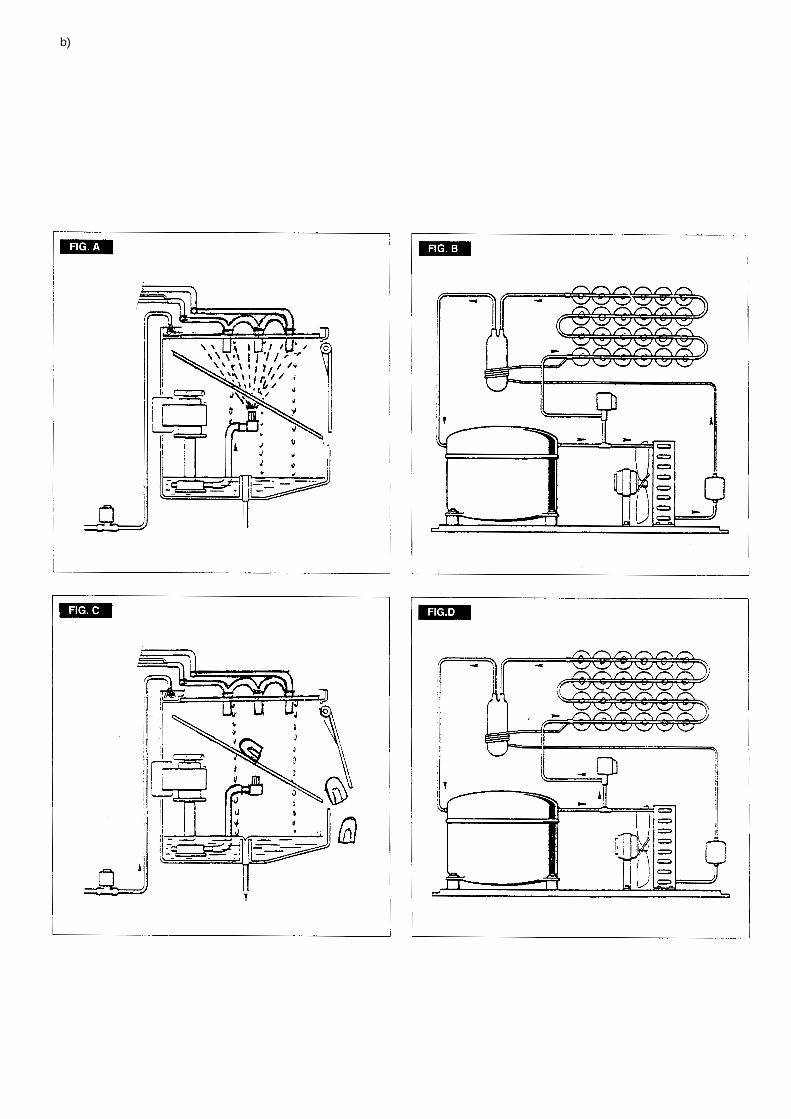
How it worksIn the ice makers the water used to make the iceis kept constantly in circulation by a water pumpwhich primes it to the spray system nozzles fromwhere it is diverted on the inverted molds of theevaporator (Fig. A).A small quantity of the sprayed water freezes intoice; the rest of it cascades by gravity into thesump assembly below for recirculation.
FREEZING CYCLE (Fig. B)
The hot gas refrigerant discharged out from thecompressor reaches the condenser where, beingcooled down, condenses into liquid. Flowing intothe liquid line it passes through the drier/filter,then it goes all the way through the capillary tubewhere it looses its pressure.Next the refrigerant enters into the evaporatorserpentine (which has a larger diameter then thecapillary tube) and starts to boil off; this reactionis emphasized by the heat transferred by thesprayed water.The refrigerant then increases in volume andchanges entirely into vapor.The vapor refrigerant then passes through thesuction accumulator (used to prevent that anysmall amount of liquid refrigerant may reach thecompressor) and through the suction line. Inboth the accumulator and the suction line itexchanges heat with the refrigerant flowing intothe capillary tube (warmer), before to be suckedin the compressor and to be recirculated as hotcompressed refrigerant gas.The freezing cycle is controlled by the evaporatorthermostat which has its bulb in contact with theevaporator serpentine.
The electrical components in operation duringthe freezing cycle are:
COMPRESSOR
WATER PUMPFAN MOTOR (in air cooled version)
The refrigerant head pressure is graduallyreduced from a value of approx. 12 bars at thebeginning of the freezing cycle with the unit at21°C ambient temperature, to a minimun valueof approx. 6 bars just at the end of the freezingcycle few seconds before the starting of thedefrost cycle.The declining of the pressure is relied to thereduction of the evaporating pressure, causedby the progressive growth of the ice thickness onthe inverted molds and to the flow of air drownthrough the air cooled condenser by the fanmotor.
The above values are in relation as well to theambient temperature of the ice maker site andthey are subject to rise with the increase of thistemperature.At the start of the freezing cycle the refrigerantsuction or lo-pressure lowers rapidly to 1.0 bar- 14 psig then it declines gradually - in relationwith the growing of the ice thickness - to reach,at the end of the cycle, approx. 0÷0.1 bar - 0÷1.5psig with the cubes fully formed on the molds.On the models water cooled version the hi-pressure controls is used to intermittentlyenergize a water solenoid valve located on thewater supply line to the condenser.
DEFROST OR HARVEST CYCLE (Fig. D)
When the temperature of the evaporatorthermostat, in contact with the evaporatorserpentine, drops to a pre-set value it changesits electrical contacts energizing the followingcomponents:COMPRESSORWATER INLET SOLENOID VALVEHOT GAS SOLENOID VALVEThe incoming water, passing through the waterinlet valve and the flow control, runs over theevaporator platen and then flows by gravitythrough the interstices down into the sump/reservoir (Fig. C).The water filling the sump/reservoir forces partof the surplus water from the previous freezingcycle to go out to the waste through the overflowpipe. This overflow limits the level of the sumpwater which will be used to produce the nextbatch of ice cubes.Meanwhile the refrigerant, as hot gas dischargedfrom the compressor, flows through the hot gasvalve directly into the evaporator serpentine by-passing the condenser.The hot gas circulating into the serpentine of theevaporator warms up the copper molds causingthe harvest of the ice cubes. The ice cubes,released from the inveted molds, drop by gravityonto a slanted cube chute, then through acurtained opening they fall into the storage bin.When the temperature of the evaporatorthermostat bulb reaches the value of +3÷4°Ctheir electrical contacts move back to the previousposition activating a new freezing cycle anddeenergizing both the hot gas and the water inletvalves (closed).
NOTE. The length of the defrost/harvestcycle (not adjustable) changes accordingto the ambient temperature (shorter for hiambient temperature and longer for lowone).

COMPONENTS DESCRIPTION
A. WATER PUMPThe water pump operates continually throughoutthe freezing cycle.The pump primes the water from the sump to thespray system and through the spray nozzlessprays it into the inverted cup molds to be frozeninto crystal clear ice cubes.It is recommended that the pump motor bearingsbe checked at least every six months.
B. WATER INLET SOLENOID VALVE -3/4 MALE FITTING
The water inlet solenoid valve is energized onlyduring the defrost cycle.When energized it allows a metered amount ofincoming water to flow over the evaporator cavityto assist the hot gas in defrosting the ice cubes.The water running over the evaporator cavitydrops by gravity, through the dribbler intersticesof the platen, into the sump reservoir.
C. HOT GAS SOLENOID VALVEThe hot gas solenoid valve consists basically intwo parts: the valve body and the valve coil.Located on the hot gas line, this valve is energizedby the contacts 3-2 of the evaporator thermostatduring the defrost cycle.During the defrost cycle the hot gas valve coil isactivated so to attract the hot gas valve piston inorder to give way to the hot gas discharged fromcompressor to flow directly into the evaporatorserpentine to defrost the formed ice cubes.
D. BIN THERMOSTATThe bin thermostat control body is located in thefront of control box behind the front louvered panel.The thermostat sensing tube is located into abulb holder on the side wall of the ice storage binwhere it automatically shuts the icemaker OFFwhen in contact with the ice and re-starts theicemaker when the ice is removed. Factorysettings are 1°C OUT and 4°C IN.
E. CUBE SIZE CONTROL (EVAPORATORTHERMOSTAT)
The cube size control (evaporator thermostat)body is located in the front of control box behindthe front louvered panel; it’s basically a reverseacting temperature control which closes thecontacts 3-2 when its temperature decreasesand closes the opposite contacts 3-4 when thetemperature rises.The thermostat sensing bulb is located into aplastic tube (bulb holder) secured by two clipsdirectly to the evaporator serpentine.This control determines the length of the freezingcycle and correspondingly the size of the cubes.A lower setting will produce a larger cube(oversize) while a higher setting a smaller cuber(shallow size).When closed on contacts 3-2 it activates thedefrost or harvest cycle components.
The cube size control is set up in the factory(knob in the black dot position) and doesn'trequire any adjustment when the ambienttemperature remains between 10 and 35°C.
NOTE. The thermostat is very sensitive!By a little movement of the knob corresponda big size change of the ice cubes. Ifnecessary only, it's recommended to makemax 1/20 of turn regulation each time.
F. FAN MOTORThe fan motor is electrically connected in parallelto the water pump and it operates continuouslyonly during the freezing cycle keeping the properhead pressure by circulating air through thecondenser fins.
G. COMPRESSORThe hermetic compressor is the heart of therefrigerant system and it is used to circulate andretrieve the refrigerant throughout the entiresystem. It compresses the low pressurerefrigerant vapor causing its temperature to riseand become high pressure hot vapor (hot gas)which is then released through the discharge valve.
H. WATER SPRAY SYSTEMThrough its nozzles it sprays the water on eachindividual inverted mold to be frozen into ice.
I SAFETY HI TEMPERATURE THERMOSTATLocated on the bottom part of the control box it isa manual reset switch that trips OFF the operationof the machine when its bulb (located on theliquid line just before the drier) reaches thetemperature of 80°C.
J. CLEANING SWITCH
Located on the bottom left side of the control boxis used to energize the water inlet and the hot gasvalves so to charge the water into the sump tankof the machine.
K. HI PRESSURE CONTROLUsed on water cooled ice makers it functions tomaintain the head pressure within the presetvalues of 6÷12 bars, by intermittently activatingthe water inlet valve to the condenser.
L. WATER INLET SOLENOID VALVE -3/4 MALE FITTING
A second water inlet solenoid valve, operatingthrough an automatic hi-pressure control, is usedon water cooled versions to supply water to thecondenser.When activated it supplies a metered amount ofwater to the condenser in order to limit its tempe-rature and the refrigerant operating high pressure.
Page 6

Page 7
MAINTENANCE AND CLEANING INSTRUCTIONS
CLEANING INSTRUCTIONS OF WATERSYSTEM
1. Remove the front and top panels to gainaccess either to the control box and to theevaporator.
2. Make sure that all ice cubes have beenreleased from their molds, then switch off theunit.
3. Prepare the cleaning solution by diluting ina plastic container one or two liters of warm water(45°-50°C) with a 0,1-0,2 liters of Ice MachineCleaner.
WARNING. The Ice Machine Cleanercontains Phosphoric and Hydroxyaceticacids.These compounds are corrosive and maycause burns if swallowed, DO NOT indu-ce vomiting. Give large amounts of wateror milk. Call Physician immediately.In case of external contact flush withwater. KEEP OUT OF THE REACH OFCHILDREN.
4. Scoop out all the ice cubes stored into thebin in order to prevent them from beingcontaminated with the cleaning solution thenflush out the water from the sump reservoir byremoving the overflow stand-pipe.
5. Remove the evaporator cover then slowlypour onto the evaporator platen the cleaningsolution. With the help of a brush dissolve themost resistant and remote scale deposits in theplaten.
6. Turn the CLEANING switch on "II-CLEAN",close the water tap and switch on the machine.
7. Allow the ice maker to operate for about 20minutes.
NOTE. The amount Cleaner and the timeneeded for the cleaning of water systemdepends of the water conditions.
8. Switch OFF then flush out the cleaningsolution from the sump reservoir then pour ontothe evaporator cavity two or three liters of cleanpotable water to rinse the molds and the platen.
9. Switch ON the machine. The water pump isagain in operation to circulate the water in orderto rinse the entire water system.
10. Do the operation as per steps 8 and 9 twiceso to be sure no more traces of descaling solutionremains into the sump.
11. Pour on the upper side of the evaporatorplaten fresh water with a capfull of disinfectantsolution then turn again the machine in normaloperating mode so to sanitize all the water systemfor approx. 10 minutes.
NOTE. Do not mix descaling with disinfectantsolution to avoid the generation of a veryaggressive acid.
12. Flush out the disinfectant solution from thesump reservoir, open the water tap then switchon the machine.
13. When water starts overflowing throughthe drain line, set the switch to "operation"position "I-ON". The unit is now ready to resumenormal operation.
14. Place again the evaporator cover and theunit service panels.
15. At completion of the freezing and harvestcycle make sure of proper texture and clearnessof the ice cubes and that, they do not have anyacid taste.
ATTENTION. In case the ice cubes arecloudy-white and have an acid taste, meltthem immediately by pouring on themsome warm water. This to prevent thatsomebody could use them.
16. Wipe clean and rinse the inner surfaces ofthe storage bin.
REMEMBER. To prevent the accumulationof undesirable bacteria it is necessary tosanitize the interior of the storage bin with ananti-algae disinfectant solution every week.

Pagina 8
INFORMAZIONI GENERALIED INSTALLAZIONE
A. INTRODUZIONE
I fabbricatori di ghiaccio in cubetti sono statiprogettati e costruiti con un elevato standardqualitativo.Essi vengono collaudati interamente per diverseore e sono in grado di assicurare il massimorendimento relativamente ad ogni particolareuso e situazione.
NOTA. Per non compromettere o ridurre lecaratteristiche di qualità e sicurezza di que-sto fabbricatore di ghiaccio si raccomanda,nell’effettuare l’installazione e le operazioniperiodiche di manutenzione, di attenersi scru-polosamente a quanto prescritto in questomanuale.
B. DISIMBALLAGGIO ED ISPEZIONE
1. Ispezionare visivamente l’imballo esternoin cartone e il basamento in legno usati per laspedizione. Qualsiasi danno evidente sull’imbal-lo esterno deve essere riferito allo spedizioniere;in questo caso, procedere ad ispezionare l’appa-recchio con il rappresentante dello spedizionierepresente.
2. a) Tagliare e rimuovere i nastri in plasticache mantengono sigillato l’imballo di cartone.
b) Aprire la parte superiore dell’imballo etogliere i fogli e gli angolari protettivi di polistirolo.
c) Sollevare l’intero cartone sfilandolo dal-l’apparecchio.
3. Togliere il pannello frontale ed il pannelloposteriore dell’apparecchio ed ispezionare lostesso onde accertare se abbia subito danni.Notificare allo spedizioniere eventuali danni su-biti come riportato al punto 1.
4. Togliere tutti i supporti interni usati per laspedizione e i nastri adesivi di protezione.
5. Controllare che le tubazioni del circuitorefrigerante non tocchino altre tubazioni o super-fici, e che il ventilatore giri liberamente.
6. Usando un panno pulito e umido, pulire lepareti interne del contenitore del ghiaccio e lesuperfici esterne dell’apparecchio.
7. Osservare i dati riportati sulla targhetta fis-sata alla parte posteriore del telaio vicino airaccordi idraulici ed elettrici, e verificare che ilvoltaggio della rete elettrica disponibile corri-
sponda a quello riportato sulla targhetta del-l’apparecchio.
ATTENZIONE. Un errato voltaggio del-l’alimentazione elettrica annullerà auto-maticamente il vostro diritto alla garan-zia.
8. Compilare la cartolina di garanzia postaall’interno del Manuale d’Uso, segnando sia ilmodello che il numero di serie dell’apparecchiorilevandolo dalla targhetta fissata al telaio.Spedire la cartolina debitamente compilata alcostruttore.
C. POSIZIONAMENTO E LIVELLAMENTO
ATTENZIONE. Questo fabbricatore dighiaccio è stato progettato per essereinstallato all’interno di locali in cui latemperatura ambiente non scenda mai aldi sotto di 10 °C ne superi i 35 °C.Periodi prolungati di funzionamento atemperature al di fuori dei seguenti limiticostituiscono cattivo uso secondo i ter-mini di garanzia e fanno decadere auto-maticamente il vostro diritto alla garan-zia.
1. Posizionare l’apparecchio nel luogo di in-stallazione definitivo.
I criteri per la sua scelta sono:
a) Minima temperatura ambiente 10°C emassima temperatura ambiente 35°C.
b) Temperature dell’acqua di alimentazio-ne: minima 5°C massima 40°C.
c) Luogo ben aerato per assicurare unefficace ventilazione all’apparecchio e quindi uncorretto funzionamento del condensatore.
d) Spazio adeguato per i collegamenti diservizio previsti nella parte posteriore dell’appa-recchio. Lasciare almeno 15 cm di spazio attor-no all’unità così da permettere una corretta edefficace circolazione d’aria soprattutto nei mo-delli raffreddati ad aria.
NOTA. Con l’apparecchio incassato la pro-duzione di ghiaccio diminuisce rispetto aquanto indica il diagramma.La capacità di produzione giornaliera variacon il variare della temperatura ambiente,dell’acqua di alimentazione e dello spaziointorno all’apparecchio.Per mantenere la produzione del vostrofabbricatore di ghiaccio a cubetti al massi-mo della sua condizione è necessario ese-guire la manutenzione periodica come pre-scritto nel relativo capitolo di questo manua-le.

Pagina 9
2. Livellare l’apparecchio in entrambe le dire-zioni, dall’anteriore alla posteriore e da sinistra adestra mediante i piedini.
NOTA. Questo fabbricatore di ghiaccio in-corpora dei componenti delicati e di massi-ma precisione pertanto bisogna evitargli urtie scossoni violenti.
D. COLLEGAMENTI ELETTRICI
Osservare la targhetta dell’apparecchio così dadeterminare, in funzione dell’amperaggio indica-to, tipo e sezione del cavo elettrico da usarsi.Tutti gli apparecchi sono muniti di un cavo dialimentazione elettrica per cui si richiede uncollegamento dello stesso ad una linea elettricaprovvista di cavo di messa a terra e che facciacapo ad un proprio interruttore magneto-termicomunito di fusibili adeguati, come indicato nellatarghetta di ogni singolo apparecchio.La variazione massima di voltaggio consentitanon deve eccedere il 10% del valore di targa oessere inferiore al 10% dello stesso. Un bassovoltaggio può causare un funzionamento ano-malo e può essere la causa di seri danni alleprotezioni ed agli avvolgimenti elettrici.
NOTA. Tutti i collegamenti esterni devonoessere fatti a regola d’arte in conformità conquanto stabilito dalle norme locali da parte dipersonale qualificato.
Prima di collegare il fabbricatore di ghiaccio allalinea elettrica accertarsi ancora una volta che ilvoltaggio dell’apparecchio, specificato sullatarghetta, corrisponda al voltaggio misurato.
E. ALIMENTAZIONE IDRAULICA E SCARICO
Premessa
Nella scelta dell’alimentazione idraulica al
fabbricatore di ghiaccio a cubetti si deve tenerepresente:
a) Lunghezza della tubazione
b) Limpidezza e purezza dell’acqua
c) Adeguata pressione dell’acqua di alimen-tazione
Una bassa pressione dell’acqua di alimentazio-ne, inferiore ad 1 bar, può causare dei disturbi difunzionamento dell’apparecchio. L’uso di acquecontenenti una quantità eccessiva di mineralidarà luogo ad una produzione di cubetti di ghiac-cio opachi e ad una notevole incrostazione delleparti interne del circuito idraulico.
Alimentazione idraulica
Collegare il raccordo da 3/4 di pollice maschiodella valvola solenoide di ingresso acqua allalinea di alimentazione idrica utilizzando il tubo inplastica rinforzato del tipo alimentare atossicofornito.La linea di alimentazione idraulica deve esseremunita di un rubinetto di intercettazione posto inun luogo accessibile nei pressi dell’apparecchio.
Scarico acquaSi consiglia di usare, come tubo di scarico, untubo in plastica rigida avente diametro interno di18 mm.Lo scarico dal condensatore, nei modelli raffred-dati ad acqua, è raccordato internamente alloscarico dell'apparecchio.Lo scarico dell’acqua in eccesso avviene pergravità; per avere un regolare deflusso è indi-spensabile che lo scarico disponga di una presad’aria e vada in un sifone aperto.
NOTA. Tutti i collegamenti idraulici devonoessere eseguiti a regola d’arte in conformitàcon le norme locali. In alcuni casi è richiestol’intervento di un idraulico patentato.

Pagina 10
F. CONTROLLO FINALE
1. L’apparecchio è stato installato in un localedove la temperatura ambiente è di almeno 10°Canche durante i mesi invernali?
2. Ci sono almeno 15 cm di spazio dietro ed ailati dell’apparecchio onde avere una efficaceventilazione del condensatore?
3. L’apparecchio è ben livellato? (IMPORTAN-TE)
4. L’apparecchio è stato collegato alla linea dialimentazione elettrica? É stato eseguito il colle-gamento alle tubazioni dell’acqua di alimentazio-ne e di scarico?
5. É stato controllato il voltaggio della linea dialimentazione elettrica? Corrisponde al voltag-gio specificato sulla targhetta dell’apparecchio?
6. É stata controllata la pressione dell’acquadi alimentazione in modo da assicurare all’appa-recchio una pressione di ingresso di almeno 1bar?
7. Controllare tutte le tubazioni del circuito
refrigerante e del circuito idraulico verificando seesistono vibrazioni o sfregamenti. Controllareinoltre che le fascette stringitubo siano ben ser-rate e che i cavetti elettrici siano fermamentecollegati.
8. Sono stati controllati i bulloni di ancoraggiodel compressore? Permettono a questi di oscilla-re sui propri supporti?
9. Le pareti interne del contenitore del ghiac-cio e le pareti esterne dell’apparecchio sonostate pulite?
10. É stato consegnato il libretto di istruzione esono state date al proprietario le istruzioni neces-sarie per il funzionamento e la manutenzioneperiodica dell’apparecchio?
11. La cartolina di garanzia è stata compilata?
Controllare il numero di serie ed il modello sullatarghetta dell’apparecchio, quindi spedirla alcostruttore.
12. É stato dato al proprietario il nome ed ilnumero telefonico del servizio di assistenza tec-nica autorizzato della zona?
G. SCHEMA DI INSTALLAZIONE
1. Rubinetto di intercettazione
2. Filtro acqua
3. Linea di alimentazione idraulica
4. Raccordo da 3/4 di pollice
5. Scarico ventilato
6. Scarico acqua con sifone ventilato
7. Raccordo di scarico
8. Interruttore principale
9. Linea elettrica
ATTENZIONE. Questo fabbricatore di ghiaccio non è stato progettato per essere installatoall’aperto o per funzionare a delle temperature ambienti inferiori a 10 °C o superiori a 35 °C.Lo stesso vale per la temperatura dell’acqua di alimentazione che non deve essere inferiorea 5°C o superiore a 40 °C.

Pagina 11
Verificare che la tendina di plastica sia posizio-nata correttamente impedendo la fuoriuscitadell’acqua attraverso le proprie lamelle.
G. Il processo di fabbricazione del ghiaccio hacosì inizio con l’acqua che viene continuamentespruzzata sugli stampini rovesciati e con la tem-peratura dell’evaporatore che gradualmente siabbassa.
H. Quando la temperatura dell'evaporatoreraggiunge un valore predeterminato il termosta-to evaporatore commuta i suoi contatti dandoluogo alla fine del ciclo di congelamento edall'inizio del ciclo di scongelamento.
I. Verificare che durante la fase discongelamento l’acqua di alimentazione vada areintegrare quella precedentemente usata per laproduzione dei cubetti e che quella eccedentetrabocchi nel tubo di troppo pieno e fluisca nellatubazione di scarico dell’apparecchio.
J. Osservare i cubetti di ghiaccio prodotti.Questi devono essere della giusta dimensione.Nel caso contrario, attendere il secondo ciclo diproduzione del ghiaccio, prima di effettuare qual-siasi regolazione.
K. Se necessario la durata del ciclo dicongelamento può essere modificata ruotandocon piccolissimi spostamenti (spostare di 1/20 digiro per volta) la manopola del termostatoevaporatore posta nella parte frontale della sca-tola elettrica fino al raggiungimento della dimen-sione ottimale.Controllare l'aspetto dei cubetti di ghiaccio pro-dotti: cubetti aventi delle corrette dimensioniesterne ma particolarmente opachi, indicanoche il fabbricatore di ghiaccio ha avuto unamancanza d'acqua durante la fase finale delciclo di congelamento o che, l'acqua usata per laproduzione del ghiaccio è di pessima qualità equindi si rende necessario l'uso di filtri adeguatio di un condizionatore d'acqua.
L. Durante il ciclo di sbrinamento, coprire conuna manciata di cubetti il bulbo sensibile deltermostato contenitore e verificare lo spegni-mento dell'apparecchio dopo circa due o treminuti.Togliere la manciata di cubetti dal bulbo sensibi-le e controllare che l'apparecchio si rimetta inmoto in circa tre o quattro minuti.
M. Rimontare i pannelli precedentemente ri-mossi quindi istruire il proprietario sul funziona-mento del fabbricatore di ghiaccio così comesulle operazioni di pulizia ed igienizzazione delmedesimo.
ISTRUZIONI DIFUNZIONAMENTO
AVVIAMENTODopo aver correttamente installato l'apparec-chio ed averlo collegato alla rete elettrica edidraulica, seguire la seguente procedura perl'avviamento.
A. Togliere dal fabbricatore di ghiaccio il pannel-lo frontale e localizzare l'interruttore di lavaggio.
B. Spostare l'interruttore di lavaggio sulla po-sizione "II CLEAN". Questo chiude il circuitoelettrico della valvola di ingresso dell'acqua edella valvola gas caldo.
C. Spostare, a questo punto sia l'interruttoreposto sulla linea di alimentazione elettrica chel'interruttore generale dell'apparecchio sulla po-sizione ON (acceso). L'apparecchio partirà nellafase di sbrinamento con i seguenti componenti infunzione:VALVOLA INGRESSO ACQUAVALVOLA GAS CALDOSono in funzione anche la Pompa ed ilMotoventilatore (nel caso di apparecchi raffred-dati ad aria).
D. Lasciare funzionare la macchina nella fasedi sbrinamento per circa tre - quattro minuti finoad avere dell'acqua allo scarico dell'apparec-chio. Quindi spostare l'interruttore di lavaggiosulla posizione "I ON".
NOTA. Durante la fase di sbrinamento l'ac-qua entra nell'apparecchio, attraverso la val-vola solenoide di ingresso dell'acqua, eccita-ta durante questa parte del ciclo, e attraversol'apposita tubazione è indirizzata sulla partesuperiore dell'evaporatore. Dopo aver co-perto l'intera superficie di plasticadell'evaporatore, l'acqua viene scaricata, at-traverso le fessure di drenaggio, nellavaschetta di raccolta, riempiendola.
E. L'apparecchio inizia così il suo primo ciclodi congelamento con i seguenti componenti infunzione:COMPRESSOREPOMPAMOTOVENTILATORE (solo nei modelli raffred-dati ad aria)
F. Osservare attraverso l’apertura di scaricodei cubetti che la barra spruzzante sia corretta-mente posizionata e che l’acqua venga unifor-memente spruzzata sugli stampini rovesciatidell’evaporatore.

Pagina 12
PRINCIPIO DIFUNZIONAMENTONei fabbricatori di ghiaccio l’acqua usata per laproduzione del ghiaccio è tenuta costantementein movimento da una pompa elettrica che attra-verso un sistema spruzzante dirige l’acqua apressione moderata sugli stampini rovesciatidell’evaporatore. Qui una parte dell’acqua spruz-zata ghiaccia all’istante; il rimanente di essaricade nel sottostante serbatoio di recupero peressere ricircolata.
CICLO DI CONGELAMENTOIl refrigerante allo stato gassoso ed ad altatemperatura viene pompato dal compressore e,passando poi attraverso il condensatore, si tra-sforma in refrigerante allo stato liquido.La linea del liquido permette al refrigerante difluire dal condensatore al tubo capillare attraver-so il filtro deumidificatore. Durante il passaggioattraverso il tubo capillare il refrigerante allostato liquido perde gradualmente parte della suapressione e conseguentemente parte della suatemperatura. Successivamente raggiunge edentra nella serpentina dell’evaporatore.L’acqua spruzzata sugli stampini rovesciatidell’evaporatore cede calore al refrigerante cir-colante all’interno della serpentina, causandonel’evaporazione, ed il conseguente cambiamentodel suo stato fisico, cioè da liquido diviene vapo-re. Il refrigerante allo stato vaporoso dopo esse-re passato attraverso l’accumulatore viene aspi-rato nuovamente nel compressore tramite lalinea di aspirazione.Il ciclo di congelamento è regolato da un control-lo della temperatura (termostato evaporatore)che determina la durata del ciclo e di conseguen-za la dimensione dei cubetti.I componenti in funzione durante il ciclo dicongelamento sono:IL COMPRESSORELA POMPAIL VENTILATORE (nei modelli raffreddati ad aria)Nei modelli raffreddati ad aria la pressione dimandata del sistema refrigerante (alta pressio-ne) cala progressivamente da un valore di circa12 bar (con temperatura ambiente di 21°C), chesi riscontra all’inizio del ciclo di congelamento,fino ad un valore minimo di 67 bar proprio allafine del ciclo di congelamento. Questi valori sonoinfluenzati della temperatura dell’ambiente in cuiè installato l’apparecchio e aumentano propor-zionalmente con l’aumentare di quest’ultima.Con apparecchi installati in condizioni normali(21°C ambiente) la pressione di aspirazione obassa pressione scende rapidamente a 1 barall’inizio del ciclo di congelamento, cioè quandoil cubetto di ghiaccio inizia a formarsi, declinandolentamente a circa a 0÷0.1 bar allorché il cubettodi ghiaccio è completamente formato.Nei modelli raffreddati ad acqua è utilizzato unpressostato per alimentare elettricamente, inmodo intermittente, una valvola a solenoide si-tuata sulla linea idraulica di alimentazione alcondensatore.
CICLO DI SCONGELAMENTO OSBRINAMENTO
Al momento in cui il termostato evaporatoresente la temperatura corrispondente ai cubetti dighiaccio di dimensione piena, i contatti dellostesso cambiano posizione alimentando i se-guenti componenti:COMPRESSOREVALVOLA DI INGRESSO ACQUAVALVOLA DEL GAS CALDOL’acqua in immissione passa attraverso la valvo-la solenoide di ingresso ed il controllo di flussoche è posto all’interno della medesima, arrivasulla parte superiore dell’evaporatore da dovecola, attraverso le fessure di drenaggio, nelsottostante serbatoio di pescaggio della pompa.Il livello massimo dell’acqua nel serbatoio è limi-tato da un tubo di troppo pieno che ha la funzionedi indirizzare verso lo scarico l’acqua in eccesso.Il refrigerante allo stato gassoso, pompato dalcompressore, viene ora dirottato dalla valvola delgas caldo aperta direttamente alla serpentinadell’evaporatore, seguendo il percorso più diret-to cioè, non passando attraverso il condensatore.Il gas caldo circolante all’interno della serpentinadell’evaporatore, fa aumentare la temperaturadegli stampini causando quindi lo stacco daimedesimi dei cubetti di ghiaccio.I cubetti che si staccano cadono sopra una grigliainclinata da dove scivolano attraverso l’aperturacon tendina a lamelle, per cadere all’interno delcontenitore del ghiaccio.Grazie al fluire del gas caldo nella serpentinadell'evaporatore, la temperatura dello stesso salee conseguentemente sale anche la temperaturadel bulbo sensibile del termostato evaporatore ilquale cambia i suoi contatti disattivando la bobi-na della valvola gas caldo e della valvola diingresso acqua ed attivando la pompa di circola-zione dell'acqua e il ventilatore iniziando così unnuovo ciclo di congelamento.
DESCRIZIONE DEI COMPONENTI
A. POMPALa pompa opera in continuazione soltanto du-rante il ciclo di congelamento dirigendo l'acquaverso la piastra spruzzante.Dalla barra spruzzante l'acqua, attraverso glispruzzatori viene diretta sugli stampini rovesciatisubendo, in questa fase, una certa aerazionepermettendo così di ottenere un cubetto di ghiac-cio solido e cristallino.Si consiglia di controllare lo stato dei cuscinettialmeno ogni sei mesi.
B. VALVOLA SOLENOIDE DI INGRESSODELL'ACQUA - RACCORDO DA 3/4GAS MASCHIO
La valvola solenoide di ingresso dell'acqua postanella parte posteriore dell'apparecchio, è eccita-ta solamente durante il ciclo di sbrinamento.Quando è eccitata permette, ad una limitata quan-tità d'acqua, di fluire verso la parte superiore dellapiastra evaporatore assistendo così il gas caldo

Pagina 13
durante la fase di distacco dei cubetti. Quest'acquaviene quindi scaricata dalla piastra dell'evaporatore,attraverso le fessure di scarico, nel serbatoio diraccolta sottostante da dove viene aspirata dallapompa e diretta alla barra spruzzante.
C. VALVOLA SOLENOIDE DELGAS CALDO
La valvola solenoide del gas caldo è compostaessenzialmente da due parti, rispettivamente ilcorpo e la bobina. Situata sulla linea di mandatadel compressore è attivata dai contatti 3-2 (se-conda posizione), del termostato evaporatoredurante il ciclo di sbrinamento.Durante il ciclo di sbrinamento la bobina, colloca-ta sulla parte superiore della valvola gas caldo èattivata attraendo pertanto il pistoncino postoall'interno del corpo valvola.Questo apre il passaggio al gas caldo pompatodal compressore, consentendogli di fluire diret-tamente nella serpentina dell'evaporatore di-staccando così i cubetti di ghiaccio dai bicchierini.
D. TERMOSTATO CONTENITORE
Il tubo sensibile del termostato contenitore (tubocapillare) è inserito nel tubo portabulbo fissatosulla parete della cabina di deposito del ghiaccioed ha il compito di interrompere il funzionamentodell'apparecchio quando il tubo sensibile è co-perto dal ghiaccio e di farlo ripartire non appena ilghiaccio sia stato rimosso. Il termostato conteni-tore è tarato direttamente in fabbrica per fermarel'apparecchio a 1°C e riattaccarlo a 4°C.
E. TERMOSTATO EVAPORATORE(CONTROLLO DELLA DIMENSIONEDEI CUBETTI)
Il termostato evaporatore posto nella parte fron-tale della scatola elettrica, è essenzialmente uncontrollo della temperatura che chiude i suoicontatti 3-2 quando la temperatura scende (fineciclo di congelamento) e li apre chiudendo icontatti 3-4 quando la temperatura sale (fineciclo di sbrinamento).Questo controllo determina la durata del ciclo dicongelamento e di conseguenza la dimensionedei cubetti di ghiaccio. Una bassa regolazioneprodurrà cubetti di ghiaccio troppo grandi mentreal contrario un'alta regolazione produrrà cubettidi ghiaccio (troppo piccoli). I contatti del termo-stato evaporatore sulla seconda posizione (con-tatti 3-2) chiudono il circuito elettrico ai compo-nenti del ciclo di sbrinamento controllandone lasua durata.Il termostato evaporatore è regolato in fabbrica(manopola su puntino nero) e non richiedeaggiustamenti quando la temperatura ambienterimane tra 10 e 35°C.
NOTA. Il termostato è molto sensibile. Ad unpiccolo spostamento della maniglia diregolazione corrisponde un grande cambia-mento dimensionale del cubetto. Nel casosia strettamente necessario, si raccomandadi fare regolazione di 1/20 di giro per volta.
F. VENTILATOREIl ventilatore, collegato al circuito elettrico attra-verso i contatti 3-4 del termostato evaporatore,opera soltanto durante il ciclo di congelamento,facendo circolare l'aria attraverso il condensato-re e mantenendo così, entro valori prestabilitil'alta pressione.
G. COMPRESSORE ERMETICO
Il compressore ermetico ha il compito di far circo-lare il refrigerante attraverso l'intero sistema.Esso aspira il refrigerante sotto forma di vaporea bassa pressione e temperatura, lo comprime,facendone aumentare di conseguenza sia lapressione che la temperatura, e lo trasforma invapore ad alta pressione e temperatura chelascia il compressore attraverso la valvola discarico.
H. BARRA SPRUZZANTEL'acqua, forzata dalla pompa all'interno dellabarra spruzzante, fuoriesce attraverso gli spruz-zatori i quali hanno il compito di dirigere il gettodacqua verso gli stampini raffreddati dell'eva-poratore.
I. TERMOSTATO DI SICUREZZAPosto nella parte inferiore della scatola elettricaè del tipo a reinserimento manuale ed arresta ilfunzionamento dell'apparecchio quando il suobulbo (ancorato alla linea dal liquido poco primadel filtro deumidificatore) raggiunge la tempera-tura di 80°C.
J. INTERRUTTORE DI LAVAGGIOInterruttore manuale, posto nella parte sinistradella scatola elettrica eccita la bobina della val-vola del gas caldo e della valvola di ingressodell'acqua per il caricamento manuale dell'acquae per risciacquare il circuito idraulico dell'appa-recchio durante le operazioni di pulizia.
K. VALVOLA SOLENOIDE DI INGRESSOACQUA
Una seconda valvola solenoide di ingresso ac-qua, comandata da un pressostato di alta auto-matico, è prevista per alimentare il condensato-re. Quando è attivata permette ad un flussocalibrato di acqua di entrare nella serpentina diraffreddamento in modo da asportare il calore edabbassare la temperatura nonchè la pressionedel refrigerante in circolazione.
L. PRESSOSTATO DI ALTAImpiegato sia nei modelli raffreddati ad aria chead acqua mantiene entro valori prestabiliti lapressione di mandata del circuito frigorifero ali-mentando ad intermittenza la bobina della valvo-la solenoide di ingresso acqua al condensatore.
Pagina 14
8. Spegnere l'apparecchio, scaricare la solu-zione disincrostante dal serbatoio quindi versarenella parte superiore dell'evaporatore 2 o 3 litri diacqua potabile per risciacquare sia gli stampiniche la piastra in plastica.
9. Accendere l'apparecchio. La pompa è dinuovo in funzionamento per ricircolare l'acquacosì da risciacquare l'intero circuito idraulico.
10. Ripetere quanto esposto ai punti 8 e 9almeno 2 volte.
11. Versare sulla parte superioredell'evaporatore una caraffa d'acqua contenentedella sostanza battericida, quindi rimettere infunzione l'apparecchio allo scopo di igienizzaretutto il circuito idraulico per circa 10 minuti.
ATTENZIONE. Non miscelare la sostanzabattericida con il disincrostante al fine dievitare la generazione di acidi molto ag-gressivi.
12. Scaricare la soluzione disinfettante dal ser-batoio quindi aprire il rubinetto di alimentazionedell'acqua e dare tensione all'apparecchio.
13. Quando dallo scarico si nota la fuoriuscitadell'acqua posizionare l'interruttore di lavaggiosu "I ON" al fine di rimettere l'apparecchio nellecondizioni di funzionamento normale.
14. Rimontare il coperchio dell'evaporatore edi pannelli precedentemente rimossi.
15. Controllare che i cubetti di ghiaccio prodottidopo il primo ciclo di congelamento siano traspa-renti e che non abbiano sapore acidulo.
ATTENZIONE. Non utilizzare i cubetti opa-chi-bianchi e di sapore acidulo prodottidopo il procedimento di pulizia del siste-ma idraulico con il disincrostante.Per ogni evenienza è bene versare del-l'acqua tiepida all'interno del contenitorecosì da sciogliere i cubetti di ghiaccioappena prodotti.
16. Sciacquare ed asciugare le pareti internedel contenitore del ghiaccio.
NOTA. Ricordarsi che per evitare l’accumulodi batteri indesiderati è necessario pulire edigienizzare le pareti interne del contenitoreogni settimana con una soluzione di acquamista ad una sostanza battericida.
ISTRUZIONI PER LA PULIZIADEL CIRCUITO IDRAULICO
1. Togliere il pannello frontale e superiore peraccedere sia alla scatola elettrica cheall’evaporatore.
2. Attendere la fine del ciclo di sbrinamentoquindi spegnere l'apparecchio tramite l'interrut-tore principale.
3. In un secchio pulito preparare la soluzionedisincrostante diluendo in 1-2 litri di acqua pota-bile calda (45-50°C) 0,2 litri di disincrostante.
ATTENZIONE. I disincrostanti per produt-tori di ghiaccio contengono una soluzio-ne di acido fosforico e idrossiacetico.Questa soluzione è corrosiva e, se ingeri-ta, può causare disturbi intestinali. Nonprovocare il vomito. In questo caso biso-gna bere una abbondante quantità di ac-qua o di latte e chiamare subito il medico.Nel caso di contatto esterno è sufficientelavare la parte con acqua.TENERLO LONTANO DALLA PORTATADEI BAMBINI.
4. Prelevare tutto il ghiaccio stivato nel conte-nitore in modo che questi non venga contamina-to con la soluzione disincrostante quindi, scari-care l’acqua contenuta nel serbatoio dell’appa-recchio rimuovendo il tubo di troppo pieno quindiriposizionarlo.
5. Rimuovere il coperchio dell’evaporatore eversare lentamente la soluzione disincrostantetra le formine di rame. Impiegare un pennello persciogliere le incrostazioni presenti negli angolipiù remoti.
6. Posizionare l'interruttore di lavaggio su"II CLEAN", chiudere il rubinetto di alimentazionedell'acqua e dare tensione all'apparecchio trami-te l'interruttore principale.
7. Lasciare l’apparecchio in funzione per circa20 minuti.
NOTA. La quantità di disincrostante cosìcome il tempo necessario per ladisincrostazione dipendono dalle condizionidel circuito idraulico (incrostazioni).

INFORMATIONS GÉNÉRALESET INSTALLATION
A. INTRODUCTION
Dans ce manuel vous trouverez les indicationsnécessaires et la marche à suivre pour réaliser:l’installation, le démarrage, le fonctionnement,l’entretien et le nettoyage de la machine à glaceSIMAG SD 18.Ces machines ont été étudiées, conçues,construites et vérifiées avec le maximum de soinpour satisfaire la clientèle la plus exigeante.
NOTA. Pour préserver les caractéristiquesde qualité et de securité des fabriques deglace, il est fondamentale d’effectuer lesopérations d’installation et de maintenancestrictement selon les instructions indiquéesdans ce manuel de service.
B. DÉBALLAGE ET VÉRIFICATION
1. Appeller le distributeur ou le vendeur SIMAGconcerné de votre secteur.
2. Examiner l’extérieur du carton d’emballageet s’assurer qu’il n’y a pas d’avarie imputable autransport.Celle-ci pouvant entraîner un dommage cachésur la machine, exiger un examen intérieur enprésence du transporteur.
3. a) Couper et enlever les sangles maintenantle cartonnage sur son socle.
b) Ouvrir le dessus du carton et enlever laplaque et les plots d’angle de polystyrène deprotection.
c) Enlever entièrement la boîte en carton.
4. Démonter les panneaux de la machine ets’assurer qu’il n’y a pas de dégats à l’intérieur.Faire une déclaration auprès du transporteurdans le cas d’un dommage caché, comme indiquéau paragraphe 2 ci-dessus.
5. Enlever tous les supports intérieursd’emballage et les rubans adhésifs de protection.
6. S’assurer que les tuyauteries frigorifiquesne frottent, ni ne touchent, ni entre elles ni àd’autres surfaces et que l’hélice du ventilateur ducondenseur tourne librement.
7. S’assurer que le compresseur repose biensur ses “silenblocs”.
8. Utiliser un chiffon propre et humide et nettoyerles parois de la cabine de stockage et aussi lessurfaces ectérieur de la machine.
9. S’assurer que la tension d’alimentationcorrespond bien aux indications mentionnéessur la plaque signaletique fixée à l’arrière duchassis.
ATTENTION. Tout incident occasionné parl’utilisation d’une mauvaise tensiond’alimentation annulera vos droits à laGARANTIE.
10. Retirer du Mode d’Emploi la fiche de garantieet la remplir avec soin en y indiquant le type et lenumero de série relevés sur la plaquesignalétique. Envoyer un exemplaire à l’UsineSIMAG.
C. LOGEMENT ET MISE DE NIVEAU
ATTENTION. Cette machine n’est pas faitepour fonctionner à l’extérieur lorsque lestempératures de l’air ambiante sont endessous de +10 °C ou au dessus de +35 °C.Le fonctionnement prolongé hors de ceslimites est considéré annule les clausesdu contrat de garantie SIMAG.
1. Mettre en place la machine dansl’emplacement qui lui est réservé.Ou nécessaire visser les quatre pieds de mise àniveau dans les socles correspondents situéessous la base du meuble de la machine.Pour le choix de l’emplacement tenir compte:
a) température ambiante du local comprisentre +10°C et +35°C.
b) température de l’eau d’alimentationcompris entre +5°C et +40°C.
c) endroit bien ventilé pour assurer unrefroidissement correct du condenseur. Nettoyersouvent le condenseur placé dans la machine.
d) espace suffisant pour accèder auxbranchements à l’arrière. Un espace libre de 15cm minimum est nécessaire autour de l’unitépour le passage de l’air frais sur le condenseurdes groupes à air et son évacuation.
2. Mettre de niveau la machine en utilisant lespieds réglables.
D. BRANCHEMENTS ÉLECTRIQUES
Déterminer en fonction des indicationsmentionnées sur la plaque signalétique(puissance, intensité) la dimension du cablenécessaire pour l’alimentation électrique de lamachine.Tous les machines SIMAG sont expédiéescomplètement cablées avec leur cordond’alimentation électrique. S’assurer que lamachine a bien sa ligne d’alimentation qui estbranchée à un interrupteur bipolaire muralepourvu des fusibles et d’un conducteur de terre.Voir la plaque signalétique pour déterminer lecalibre du fusible.Tout le cablage extérieur devra être conformeaux normes électriques en vigueur.Vérifier la conformité du voltage de la ligned’alimentation avec la plaque d’immatriculationavant de brancher la machine.La tension admissible maximum ne doit pas
Page 15

dépasser 10% de la valeur indiquée sur la plaque,même lors du démarrage. Le sous-voltageadmissible ne doit pas dépasser 10%.Un sous-voltage peut occasionner un mauvaisfonctionnement et détériorer les contacts et lesenroulements du moteur.Avant de brancher la machine vérifiez encoreune fois la tension disponible contre les indicationsde la plaque signaletique.
NOTA. Le branchements électriques doiventêtre faites par un professionnel dans lerespect des normes locales.
E. BRANCHEMENTS D’ARRIVÉE ETD’ÉVACUATION D’EAU
Généralites
Pour le choix du mode d’alimentation d’eau sur lamachine à glaçons il faudra tenir compte:
a) du temps de fonctionnementb) de la clarté et de la pureté de l’eauc) de sa préssion
La glace est obtenue à partir de l’eau. Les pointsci-dessus sont donc importantes pour le bonfonctionnement de la machine.L’eau contenant, en quantité, des sels minérauxaura tendance à produire des cubes d’autantplus opaques qu’elle contiendra plus de sels.Une pression trop basse, inférieure à 1 bar, peutêtre une cause de mauvaise fabrication de laglace.Une eau trop fortement chlorée peut êtreaméliorée en utilisant des filtres au charbon debois ou au charbon actif.
Alimentation d’eau
Raccorder, avec le tuyau flexible en plastiquealimentaire en dotation, l’alimentation d’eaugénérale au raccord 3/4" mâle situé sur la vanneélectromagnétique d’arrivée d’eau.Installer, à un endroit accessible, entre l’arrivéeet la machine, une vanne d’arrêt.Si l’eau est très dure ou avec des impurités enexcès, il faudra mieux considerer l’applicationd’un filtre éfficace, positionné avec sa flêchedans le sens de circulation de l’eau.
Évacuation d’eau
Raccorder, avec le tuyau spiralé fourni avec lamachine, le raccord en plastique d’evacua-tion àun siphon de sol ouvert avec une pente de 3 cmpar mètre.L’évacuation du condenseur, sur les machines àeau, est raccordée au écoulement commun, àl’intérieur de la machine.Pour celà, il faut bien prévoir l’installation d’uneprise d’air verticale sur le point plus haut de latuyauterie d’évacuation, en manière d’avoir un
bon écoulement d’eau et il faut aussi s’assurerque l’eau s’écoule bien dans un siphon de solouverte.Cela afin d’éviter, en cas de mauvaise vidange,que l’eau d’évacuation du condenseur puissedégorger dans la cabine de stockage ou dans leréservoir d’eau.
NOTA. L’alimentation et l’évacuation d’eaudoivent être installées par un professionneldans le respect des normes locales.
F. LISTE DE CONTRÔLE FINAL
1. Est-ce que la machine a été placée dansune pièce où la température ambiante ne descendjamais au dessous de +10°C durant les moisd’hiver?
2. Y-a t-il au moins 15 cm d’espace libre àl’arrière et autour de la machine pour une bonneaèration?
3. La machine à t-elle été mise de niveau?
4. Tous les raccordements électriques et d’eauy compris la vanne d’arrêt ont-ils été effectués?La vanne de alimentation d'eau a été ouvert?
5. La tension électrique d’alimentationcorrespond t-elle bien aux indications de la plaquesignalétique?
6. S’est-on assuré que la préssion minimumde l’eau fournie ne sera jamais inférieur à 1 bar?Ouvrir la vanne de alimentation d'eau et vérifierque par les branchements d'eau il ny a aucunfuite.
7. Avez-vous vérifié que toutes les tuyauteriesfrigorifiques et autres sont à l’abri des vibrations,de l’usure et d’un éventuel défaut?
8. Les boulons de blocage du compresseuront-ils été retirés? S’assurer que le compresseurest bien calé sur ses silenblocs.
9. La cabine et l’extérieur de la machine à t’elleété essuyés proprement?
10. Avez-vous bien remis le manuel contenantles instructions d’utilisation au client? Avez-vousattiré son attention sur l’importance de l’entretienpériodique de la machine?
11. Avez-vous rempli correctement la fiche degarantie? Avez-vous bien vérifié le type et lenuméro de série sur la plaque avant de l’envoyer?
12. Avez-vous donné le nom du client et sonnuméro de téléphone au représentamt localSIMAG de son secteur?
Page 16

Page 17
G. INSTALLATION PRATIQUE
1. Vanne d’arrêt2. Filtre d’eau3. Alimentation d’eau4. Raccord de 3/4 mâle5. Évacuation avec prise d’air6. Évacuation d’eau à siphon7. Raccord d’évacuation8. Interrupteur général9. Ligne d’alimentation électrique
ATTENTION. Cette machine à glace n’est pas prévue pour fonctionner à l’extérieur.L’utiliser pour des trmpératures ambiante comprises entre +10 °C et +35°C et d’eau comprisesentre +5 °C et +40°C.
Page 18
INSTRUCTIONS DEFONCTIONNEMENT
DÉMARRAGE
Après avoir installé correctement la fabrique deglace et avoir completé le branchementshydrauliques et électriques, effectuez lesopérations de démarrage ci-dessous:
A. Enlever le panneau frontal et localiser leboîtier de contrôle.
B. Positionner l’interrupteur de nettoyage surla position II pour alimenter les bobines de lavanned’arrivé d’eau et de gaz chauds.
C. Mettre l’interrupteur principale en positionON (Marche)pour mettre la machine sous tension.L’appareil démarre donc sur le cycle de“demoulage” avec les suivants cmposants enfonctionnement.VANNE D’ARRIVEE D’EAUVANNE DE GAZ CHAUDSVENTILATEUR (pour les machines refroidis parair)COMPRESSEUR
D. Laissez la machine dans la phase deremplissage d'eau par trois/quatre minutesjusqu'à ce que l'eau arrive en correspondanceau trop plain (eau écoule par la vidange) puisrepositionner l'interrupteur de nettoyage sur laposition FONCTIONNEMENT (I).Pendant la phase de remplissage d’eau/degivrage, vérifiez que l’eau, qui arrive sur laplatine évaporateur, s’écoule et tombe bien dansle réservoir d’eau.Dans le réservoir le niveau d’eau montegraduellement jusqu’à ce qu’il arrive encorrespondance du trop plein, l’eau en excés quicontinue à arriver dans le réservoir s’écoule, parle trop plein, dans la vidange.La machine est maintenant prête pour son premiercycle de congélation.
E. À la fin de la phase de remplissage d’eau/degivrage la machine passe automatiquementen cycle de congélation avec le démarrage deséléments suivants (Fig. 1):COMPRESSEURPOMPE A EAUVENTILATEUR (pour les machines refroidis parair)
F. Vérifiez, à travers l’ouverture de passage deglaçons, que le systéme d’arrosage d’eau soitbien positionné et que l’eau vienne à bien êtreaspergé vers les moules de l’évaporateur et que
les lamelles en plastique du rideau sont bien librede basculer et qu’il n’y à pas de l’eau qui passeau travers celles ci.
G. Le processus de fabrication de glacecommence lorsque l’eau est aspergé sur lesmoules.Ceux-ci viennent à être graduellement réfrigeréspar l’évaporation du réfrigérant qui circule dansle serpentin d’évaporateur.
H. Lorseque le bulbe du thermostatévaporateur, logé sur la serpentine d’évaporateur,atteint la température d’enclanchement changesde position pour faire demarré le cycle dedégivrage.
I. Contrôlez, pendant le cycle de démoulage,que l’eau qui arrive dans la machine, coule biensur la platine évaporateur, pour tomber dans leréservoir, de manière de rétablir le niveau d’eaujusqu’au bord du trop plein.Vérifiez aussi que le surplus d’eau s’ecoule bienà la vidange.
J. Contrôlez l’apparence et la forme desglaçons qui viennent de tomber dans la cabine.Les glaçons corrects doivent avoir un épaisseurde environ 7÷8 mm.Lorsqu’ils ne sont pas conformes, attendre la findu second cycle avant de faire un réglage a l’aiddu thermostat evaporateur en tournant sa vis deréglage.Cette vis doit être tourné dans le sens desaiguilles d’une montre pour avoir un épaisseursupérieur et a l’inverse pour reduire l’épaisseur.Si les glaçons se presentent opaques et avec uncreux trop profond dans leur centre, cela peutprovenir d’une manque partielle d’eau qui s’estvérifiée pendant la phase finale du cycle decongélation ou, il peut bien provenir d’unemauvaise qualité de l’eau.Pour ce dernier cas, il sera nécessaire d’avoir unfiltre ou un équipement de traitement d’eau.
K. Durant le démoulage, maintenir une poignéedes glaçons contre le bulbe du thermostat cabinepour vérifier le correct fonctionnement de cedispositif.La fabrique à glace doit s’arrêter dans environs30 seconds 1 minute, exactement quand latempérature du bulbe a atteint +1°C, chose quiprovoque l’ouverture des contacts du thermostat.Retirée la poignée de cubes du contact avec lebulbe, la machine se remet automatiquement enroute - lorsque la température du bulbe monte à+4°C - en démarrant par la phase de demoulage.Remontez des panneaux enlevés avant.
L. Expliquez avec soin au client/utilisateur lesspécifications importantes de la machine, la miseen route et l’entretien, en parcourant toutes lesprocédures dans le MODE D’EMPLOI.
Page 19
PRINCIPE DEFONCTIONNEMENT
Dans les machines à glaçons SIMAG l’eau pourla fabrication de la glace est continuellement enmouvement.Une pompe électrique de circulation la pulvérisesous une pression adéquate à travers les jetsdans les moules de l’évaporateur.Une partie de cette eau se cristalise au contactdes moules réfrigérés. La glace obtenue enforme de cloche sur les parois remplit petit à petitles moules donnant les glaçons finals.
CYCLE DE CONGELATION
Le gaz réfrigérant est refoulé par le compresseurdans le condenseur, où il est refroidi et condenséen liquide par l’air ou par l’eau de refroidissement.Le réfrigérant liquide traverse le filtre déshydrateuret passe en suite par le tube capillaire où,l’échange de chaleur lui fait perdre un peu de sapression et de sa température.Le réfrigérant liquide pénètre dans le serpentinévaporateur (qui est un tube de diamètre supérieurà celui du capillaire) où il se détend et commenceà partiellement s’évaporer.Ce changement d’état est aussi provoqué parl’eau aspergé dans les moules qui fournit lachaleur nécessaire pour l’évaporation complètedu réfrigérant.Le réfrigérant en vapeur passe en suite au traversde l’accumulateur, où toute trace de liquide estvaporisé, puis retourne au compresseurtotalement en vapeur - via tuyauterie d’aspirationoù il échange de la chaleur avec le capillaire -pour être refoulé de nouveau.Le cycle de congélation est contrôlé par lethermostat évaporateur qui a son bulbe en contactavec la serpentine évaporateur.Les composants électriques en fonctionnementpendant le cycle de congèlation sont:
COMPRESSEURVENTILATEUR (Pour les machines refroidis parair)POMPE A EAU
Pour les modeles refroidis par air pendant lecycle de congélation, la haute préssion duréfrigérant varie entre 6÷12 bars.
NOTA. Dans le cas où la température (orpression correspondant) du condenseurmonte à un valeur supérieur à 70/75°C acause d'une manque partiale or totale d'eaude refroidissement, or du condenseur bloquépar la saleté pour le versions refroidis par air,un dispositif de sécurité par activationmanuel arrête le fonctionnement de lamachine.Après avoir examiné la raison de l'arrét etavoir remedié la situation, il faut the presserbe bouton de rearmement en passant parles trou sur le panneau avant or remuer lemême.
Au départ du cycle de congélation la pressiond’aspiration descend assez rapidement sur lavaleur de 1 bars puis elle s’abaisse graduellementen rélation avec l’augmentation graduelled’épaisseur glaçons pour atteindre à la fin ducycle à 0,1 bars quand les glaçons sont formés.
CYCLE DE DEMOULAGE
Lorsque la température correspondante à ladimension requise pour les cubes de glace, estatteinte dans l'évaporateur, le contact duthermostat ferme le circuit sur les composantssuivants:COMPRESSEURVENTILATEURVANNE D’ARRIVEE D’EAUVANNE GAZ CHAUDSL’eau qui arrive dans la machine, en passant parla vanne d’arrivée et par le limiteur de débit,s’écoule sur la platine évaporateur, dont l’eautravers les fissures d’écoulement et tombe dansle réservoir. Cette eau se mélange avec celle quiest restée du cycle précedent, pour faire monterle niveau jusqu’au bord du trop plein.L’excés d’eau du réservoir s’évacue par le tropplein de la vidange, de ce fait limite laconcentration des sels mineraux dans le réservoir.Entre temps les gaz chauds déchargé par lecompresseur sont déviés par la vanne de gazchauds ouverte, directement dans le serpentinévaporateur. Le gaz chauds qui circulent dans leserpentine évaporateur chauffent suffisementles moules pour faire décoller les glaçons formés.Les glaçons liberés tombent sur le plan de chuteet ils sont canalisés, au travers de l’ouverture desortie glace, dans la cabine de stockage. A la findu cycle de dégivrage les deux vannes, celle degaz chauds et celle d’arrivée d’eau, viennent àêtre désactivées, permettant ainsi à la machinede commencer un nouveau cycle de congélation.
DESCRIPTION DES COMPOSANTS
A. POMPE A EAU
La pompe à eau fonctionne en permanencependant la phase de congélation et réfoule l’eauen direction du système d’arrosage pourl’asperger à l’intérieur des moules; en ce faisant,l’eau vient à être aèrée, chose qui permet laformation de glaçons transparents et solides.Il est recommandé de vérifier les roulements dumoteur de la pompe tous les six mois.
B. ÉLECTROVANNE D’ADMISSION D’EAU
L’électrovanne d’admission d’eau est activépendant la phase de démoulage et de remplissaged’eau. Quand elle est activée une quantité d’eausuffisante circule entre les moules de la platineévaporateur, aidant ainsi le gaz chauds àdémouler les glaçons.L’eau s’écoule à travers les trous de la platinepour tomber dans le réservoir, situé sousl’évaporateur, d’où elle est recyclée par la pompeà eau en direction du système d’arrosage.

C. ÉLECTROVANNE DE GAZ CHAUDL’électrovanne de gaz chauds comprend deuxparties: le corps avec son noyau plongeur et labobine.Elle est montée sur la ligne de refoulement ducompresseur et est alimentée par les contacts duthermostat evaporateur pendant le cycle dedémoulage et pendant le cycle de remplissaged’eau.Pendant le démoulage, la bobine, placée audessous du corps de la vanne, est excitée attirantainsi le noyau plongeur à l’intérieur du corps dela vanne pour dévier le gaz chauds, provenant ducompresseur, directement dans la serpentineévaporateur pour dégivrer les glaçons formées.
D. THERMOSTAT CABINE
Le thermostat cabine a son bulbe fixé sur unedes parois intérieures de la cabine des depôt dela glace et il arrêt le fonctionnement de la machinequand son bulbe vient a se trouver en contactavec les glaçons.Il est règlé à l'usine pour couper à + 1°C etenclencher à + 4°C.Vérifier, avant remplacement, son bonfonctionnement en plaçant de la glace sur lebulbe avant de le monter sur la machine.Un déclit audible indiquera la coupure.
E. THERMOSTAT CONTROLANT LADIMENSION DES CUBES OUTHERMOSTAT D'EVAPORATEUR
Le thermostat est logé dans la boitier electrique,à l'interieur de la machine. Son fonctionnementest lié à la température de l'evaporateur parintermédiaire de son bulbe placé sur un de sestubes.Cet appareil fixe la durée du cycle de congélationet, parallèlement, la dimension des cubes.Une coupure plus basse produira un plus groscube, alors qu'une coupure plus haute donneraun cube plus petit.En tournant dans le sens des aiguilles d'unemontre, la coupure se fait sur + froid, inversementsur - froid avec en butée, une position "STOP".Réglé en usine, il est recommandé d'agirprogressivement et peu à la fois à chaque règlage.Si le premier contact est lié à la température, lesecond est inverseur. Il commande et contrôleles composants du cycle de démoulage.
F. MOTOVENTILATEUR
Le motoventilateur est branché a les contacts 3-4 du thermostat évaporateur, en parallel avec lapompe a eau, et il est en fonctionnement continupendant le cycle de congélation pour maintenir lahaute pression entre les valeurs preetablis.
Page 20
G. COMPRESSEUR
Le compresseur, du type hermétique, est le coeurdu circuit réfrigérant, il véhicule et récupère leréfrigérant à travers l'ensemble du système.Il comprime le réfrigérant vapeur, à bassepression, augmentant ainsi sa température et letransforme en gaz chauds à haute pression quivient déchargé par le clapet de réfoulement.
H. SYSTÈME D'ARROSSAGE D'EAU
 travers ses gicleurs, le système d'arrosageasperge d'eau les moules réfrigéres del'évaporateur et ce grace a la pompe a eau quimet le circuit hydraulique sous pression.
I. THERMOSTAT DE SECIRITÉ(par activation manuel)
Fixé sur le tuyau du liquide sortant du condenseurce appareil est électriquement branché en amontde tous autre dispositifs de contrôle et il arrêt lefonctionnement de la machine quand a senti quela température de la ligne liquide a montée à75°C or pression correspondant.
J. INTERRUPTEUR DE NETTOYAGE (I-II)
Interrupteur manuel "Cleaning-Opérations" logésur la boitier électrique, alimentant les vannesélectromagnétiques d'eau et de "gaz chauds"pour assurer le dégivrage manuel et le rinçage ducircuit d'eau lors des operations de nettoyage.
K. ÉLECTROVANNE D'ADMISSIOND'EAU (Modeles refroidi par eau)
Une électrovanne d’arrivée d’eau spécial estutilisée sur les machines refroidis par eau avecune entre et deux sorties pour alimenter d’eau lecondenseur et le réservoir (cuve). Cette deuxiemesortie de l’électrovanne est commande par unpressostat H.P. et elle faites arriver au condenseurun débit d’eau adequate pour maintenir la valeurde pression de condensation entre la plagevoulue.
L. PRESSOSTAT H.P.(Modeles refroidi par eau)
Utilisée seulement sur les machines refroidis pareau le pressostat H.P. contrôle le fonctionnementde la vanne d’alimentation d’eau au condenseurpour limiter les variations de la pression de lacondensation selon la température de l’eau(9,5÷10,5 bar).

INSTRUCTIONSD’ENTRETIEN ET DENETTOYAGE
A. GÉNÉRALITES
La fréquence et le mode d’emploi pour l’entretienet le nettoyage sont donnés à titre indicatif et neconstituent pas une règle absolue d’utilisation.La fréquence de nettoyage variera en fonctiondes conditions de température ambiante du localet de l’eau et aussi de la quantité de glaceproduite.Chaque machine doit être entretenuindividuellement en conformité avec son utilisationpropre.
B. ENTRETIEN
NETTOYAGE DU CIRCUIT D’EAU
1. Enlevez les panneaux dévant et supérieurde manière à avoir accès à la boîte de contrôle età l’évaporateur.
2. Attendez que la machine complète le cycleen cours et termine aussi le démoulage puispositionner l’interrupteur général sur la position“OFF” et fermer la vanne d'arrêt d'eau.
3. Enlevez toute la glace deposée dans lacabine de stockage pour éviter qu’elle soitcontaminée par la solution de nettoyage puis,videz le réservoir d’eau en enlevant le tube detrop plein ou le bouchon de vidange du réservoirou, pour les machines qu’y sont equipés, courbezvers le bas le tuyau plastique de vidange d’eau.
4. Préparez la solution de nettoyage suivante:mélangez environ 200÷300 gr de Détartrantepour machine a glaçons dans 3 lt. environ d’eauchaude (45÷50 °C) contenue dans un bac enplastique (code 001009 01).
ADVERTISSEMENT. Le produit denettoyage Ice Machine Cleaner contientde l’acide phosphorique et de l’acidehydroxyacétique.Ces constituants sont corrosif et peuventprovoquer des brulures en casd’absorption. NE PAS PROVOQUER DEVOMISSEMENT.Administrer de grandes quantité d’eau oude lait. Appeler immédiatement lemédecin. En cas de contact externe, rincerabondamment avec de l’eau. GARDERHORS DE PORTEE DES ENFANTS.
5. Démontez le couvercle d’évaporateur puisverser lentement sur l’évaporateur la solutionpréparée avant.A l’aide d’un pinceau nettoyez les points cachésoù les dépôts calcaires sont plus résistents.
6. Positionnez l’interrupteur de lavage sur laposition II CLEAN et alimenter la machine atravers l'interrupteur général.
NOTA. Quand la machine est en LAVAGE,le seul composant en fonctionnement est lapompe à eau qui doit faire circuler la solutionde nettoyage à l’intérieur du circuit d’eau.
7. Laissez la machine à glace fonctionner danscette position pendant environ 20-25 minutespuis arrêter la machine avec l’interrupteurgénéral.
8. Vidangez le réservoir d’eau pour le libérerde la solution de nettoyage utilisée puis, àplusieures réprises, versez sur l’évaporateur deuxou trois carafes d’eau potable avec le produitbactéricide code 264000 02 afin de faire un bonrinçage et sterilizer le système hydraulique de lamachine.Si nécessaire enlevez le système d’arrosagepour le nettoyer soigneusement à la main.
9. Positioner l’interrupteur général sur “ON”pour alimenter de nouveau la machine.La pompe à eau cette fois réfoule simplementl’eau versée avant, avec le liquide bactéricide,sur l’évaporateur pour rinçer les parties intérieuresde la machine et pour le steriliser dans le mêmetemps.Attendre 10 minutes environ, puis arrêter lamachine et vidanger l’eau contenue dans lacuve.
10. Ouvrir la vanne d'arrête d'eau et mettre lamachine en marche.Si faisant, ont vient d’activer la vanne d’arrivéed’eau pour permettre un correct remplissage etla pompe a eau.
11. Une fois que le niveau d’eau déborde par letrop plein (eau qui coule par le tuyau de vidange)il faut mettre l’interrupteur sur I ON au but defaire marcher la machine en fonctionnementautomatique.
12. Rémplacez le couvercle de l’évaporateur etremontez les panneaux enlevés avant.
13. Quand le cycle est completé et les glaçonssont démoulés examinez chaque cube de glacepour s’assurer qu’ils sont bien transparent et quetout le goût acide a été eliminé.
ATTENTION. Si les glaçons sont opaqueset ils ont un goût acide il faut les fairefondre en versant sur eux de l’eau chaude.
14. Nettoyez avec un chiffon propre les paroisintérieures de la cabine de stockage.
RAPPELEZ. que pour prévenir l’accu-mulation des bactéries ou micro-organismesindésirables il est bien nécessaire de stérilisertoutes les semaines l’intérieur de la cabinede stockage à l’aide du produit desinfectant/anti algues.
Page 21

ALLGEMEINESINFORMATIONEN UNDINSTALLATION
A. EINLEITUNG
Die Eiswürfelbereiter wurden für hohenQualitätsstandard entwickelt und hergestellt.Jede Maschine wird mehrere Stunden lang geprüftund ist in der Lage, maximale Leistung in jederSituation und bei jeder spezifischen Nutzung zugarantieren.
ANMERKUNG. Um die Qualitäts- undSicherheitseigenschaften diesesEiswürfelbereiters nicht zu beeinträchtigenoder zu vermindern, wird geraten, sichwährend der Installation und derWartungsarbeiten genau an dieses Handbuchzu halten.
B. AUSPACKEN UND KONTROLLE
1. Führen Sie eine Sichtkontrolle derKartonverpackung und der Holzbasis, welche fürden Versand benutzt wurden, durch. JederSchaden an der Verpackung muß an denTransporteur weitergeleitet werden; in diesemFall setzt man die Kontrolle im Beisein desVertreters des Transporteurs fort.
2. a) Entfernen Sie die Plastikbänder, die dieKartonverpackung geschlossen halten
b) Öffnen Sie den oberen Teil derVerpackung und entfernen Sie die Polystirolblätterund -Ecken
c) Heben Sie den ganzen Karton an undziehen Sie ihn vom Gerät ab
3. Nehmen Sie jetzt den vorderen und hinterenSchutz vom Gerät ab und untersuchen Sie dasGerät auf eventuelle Schäden.Teilen Sie dem Transporteur sofort eventuelleSchäden mit und gehen Sie wie bei Punkt 1 vor.
4. Nehmen Sie alle internen Stützen für denTransport und die Klebebänder ab
5. Kontrollieren Sie, daß die Leitungen desKühlkreislaufes nicht mit anderen Leitungen oderOberflächen in Berührung kommen und daß derVentilator sich frei drehen kann.
6. Mit einem sauberen feuchten Tuch säubertman die Innenwände des Eisbehälters und dieäußeren Oberflächen des Gerätes.
7. Kontrollieren Sie die Daten auf dem Schildan der Rückseite des Rahmens neben denhydraulischen und elektrischen Anschlüssen, undkontrollieren Sie, ob die elektrische Versorgungmit der übereinstimmt, die auf demselben Schildangegeben ist.
ACHTUNG. Bei falscher elektrischerVersorgung erlischt automatisch IhrAnrecht auf Garantie.
8. Füllen Sie die Garantiekarte im Innern desHandbuches aus, indem Sie sowohl das Modell,als auch die Seriennummer des Gerätesangeben, die Sie dem Schild auf dem Rahmenentnehmen können.
C. POSITIONIERUNG UNDAUSGLEICHUNG
ACHTUNG. Dieser Eiswürfelbereiterwurde dazu entwickelt, um inInnenräumen aufgestellt zu werden, indenen eine Raumtemperatur herrscht, dienie unter 10 °C sinkt oder über 35 °C steigt.
Längere Funktionszeiträume beiTemperaturen außerhalb derobenstehenden Grenzwerte stellen einefalsche Nutzung nach denGarantiebedingungen dar, wodurch derAnspruch auf Garantie erlischt.
1. Stellen Sie das Gerät am endgültigenStandpunkt auf.Die Kriterien für denselben sind:
a) Raumtemperatur mindestens 10°C undhöchstens 35°C.
b) Temperatur der Wasserversorgung:mindestens 5°C und höchstens 40°C
c) Gut belüfteter Ort, um eine gute Ventilationdes Gerätes und damit die korrekte Funktion desKondensators zu garantieren
d) Angemessener Platz für die Anschlüsse,die auf der Rückseite des Gerätes angeordnetsind. Man läßt mindestens 15 cm Raum um dasGerät, damit eine korrekte und wirksameLuftzirkulation möglich ist; besonders beiAusführungen, die mit Luft gekühlt werden.
ANMERKUNG. Bei eingebautem Gerätreduziert sich die Eisproduktion gemäßDiagramm.Die tägliche Produktionskapazität ändert sichmit der Raumtemperatur, derWasserversorgung und dem Freiraum umdas Gerät.Um die Produktion Ihres Eiswürfelbereiterszu maximieren, ist es notwendig, dieregelmäßige Wartung gemäß dementsprechenden Kapitel dieses Handbuchesauszuführen.
2. Richten Sie das Gerät durch die Füße, vonvorne nach hinten und von links nach rechts inbeiden Richtungen aus.
ANMERKUNG. Dieser Eiswürfelbereiterbeinhaltet empfindliche Bauteile höchsterPräzision. Daher müssen Stöße und starkeErschütterungen vermieden werden.
Seite 22

Seite 23
D. ELEKTRISCHE ANSCHLÜSSE
Beachten Sie das Schild des Gerätes, um dannden Querschnitt und das Kabel entsprechendder angegeben Spannung zu wählen.Alle Geräte besitzen ein elektrisches Kabel fürdie Stromversorgung, das an ein Stromnetz miteinem Erdungskabel angeschlossen werdenmuß, welches mit einem eigenenThermomagnetschalter mit entsprechenderSicherung versehen ist, wie aus vom Schildjedes einzelnen Gerätes abzulesen ist.Die maximale Spannungsdifferenz darf maximal10% des auf dem Schild angegebenen Wertesüber- oder unterschreiten. Ein zu niedrigerSpannungswert kann abnormale Funktionen undschwere Schäden der Schutzvorrichtungen undelektrischen Spulen hervorrufen.
ANMERKUNG. Alle externen Anschlüssemüssen nach allen Regeln der Kunst undnach den örtlichen Gesetzen undBestimmungen von qualifiziertem Personalausgeführt werden.
Bevor man den Eiswürfelbereiter an dasStromnetz anschließt, prüft man nochmals, daßder gemessene Spannungswert der Spannungentspricht, die auf dem Schild angegeben ist.
E. HYDRAULISCHE VERSORGUNGUND ABFLUSS
VoraussetzungBei der Wahl der hydraulischen Versorgung desEiswürfelbereiters muß folgendes beachtetwerden:
a) Länge der Leitungenb) Sauberkeit und Reinheit des Wassersc) Angemessener Wasserversorgungs-
druck.
Ein niedriger Wasserversorgungsdruck, unter 1bar, kann Störungen der Funktion des Geräteshervorrufen. Der Einsatz von Wasser mit zuhohem Mineralanteil verursacht die Produktionvon trüben Würfeln und hat Ablagerungen in deninternen Teile der Wasserleitung zur Folge.
Wasserversorgung
Den Gewindezapfen-Anschluß zu 3/4 Zoll desSolenoidventils für den Wassereingang an dieWasserversorgungsleitung mit dem mitgelie-ferten Plastikschlauch Typ Lebensmittelungiftiganschließen.Die Wasserversorgungsleitung muß mit einemWasserhahn versehen sein, der sich in der Nähedes Gerätes befindet und gut zugänglich ist.
Wasserabfluß
Es wird ein Plastikschlauch mit einemInnendurchmesser von 18 mm als Abflußleitungempfohlen.Der Abfluss des Kondensators ist bei denwassergekühlten Versionen, im inneren amAbfluss des Geräts verbunden.Der Wasserabfluß erfolgt durch Schwerkraft.Um einen ausgeglichenen Abfluß zu garantieren,ist es notwendig, daß die Abflußleitung mit einerBelüftungshaube versehen ist und in einenoffenen Siphon abgeht.
ANMERKUNG. Alle hydraulischenAnschlüsse müssen nach alle Regeln derKunst und in Übereinstimmung mit denörtlichen Gesetzen und Bestimmungenausgeführt werden. In einigen Fällen ist derEingriff eines Installateurs erforderlich.

Seite 24
F. ENDKONTROLLE
1. Wurde das Gerät in einem Raum aufgestellt,in dem die Mindesttemperatur von 10°C auch inden Wintermonaten nicht unterschritten wird?
2. Befinden sich mindestens 15 cm Freiraumhinter dem Gerät und an den Seiten, damit einegute Ventilation des Kondensators gewährleistetist?
3. Ist das Gerät gut livelliert? (SEHRWICHTIG)
4. Wurde das Gerät an das Stromnetzangeschlossen? Wurde der Anschluß an dieWasserleitungen und die Abflußleitungenausgeführt?
5. Wurden die Spannungswerte derStromversorgung geprüft? Entspricht dieSpannung den Angaben auf dem Schild desGerätes?
6. Wurde der Wasserdruck kontrolliert, damitdem Gerät ein Eingangsdruck von mindestens 1bar zur Verfügung steht?
7. Alle Leitungen des Kühlkreislaufes und desWasserkreislaufes müssen auf Vibrationen oderReibung kontrolliert werden. Ebenfalls mußkontrolliert werden, daß die Schlauchschellengut angezogen und die elektrischen Kabel festangeschlossen sind.
8. Wurden die Muttern, die den Kompressorverankern, kontrolliert? Erlauben diese eineSchwingung der eigenen Halterungen?
9. Wurden die Innenwände des Eisbehältersund die Außenwände des Gerätes gesäubert?
10. Wurde das Handbuch mit den Anweisungenabgeliefert und wurden dem Besitzer dienotwendigen Instruktionen für die Funktion unddie periodische Wartung des Gerätes gegeben?
11. Wurde die Garantiekarte ausgefüllt?Seriennummer und das Modell auf dem Schilddes Gerätes kontrollieren und dann an denHersteller senden.
12. Wurden dem Besitzer der Name und dieTelefonnummer des Kundendienstes seinesBereiches übergeben?
ACHTUNG. Dieser Eisbereiter wurde nicht für die Installation im Freien oder für den Betriebbei Raumtemperaturen unter 10 °C oder über 35 °C entwickelt. Dasselbe gilt für dieWassertemperatur, die nicht unter 5 °C oder über 40 °C liegen darf.
G. INSTALLATIONSSCHEMA
1. Wasserhahn
2. Wasserfilter
3. Wasserversorgungsleitung
4. Anschluß 3/4 Zoll
5. Belüfteter Abfluß
6. Wasserabfluß mit belüftetem Siphon
7. Abflußanschluß
8. Hauptschalter
9. Elektrische Leitung

Seite 25
ANWEISUNGEN FÜR DIEFUNKTION
INBETRIEBNAHME
Wenn das Gerät richtig installiert und an dasStrom- und Wassernetz angeschlossen ist,folgendermaßen vorgehen:
A. Die vordere Platte vom Eisbereiterabnehmen und den Schalter für den Spülvorgangausfindig machen.
B. Den Schalter für den Spülvorgang auf diePosition „IICLEAN” stellen. Dies schließt denelektrischen Kreislauf des Wasser-Eingangsventils und des Warmgasventils
C. Nun stellt man sowohl den Schalter an derelektrischen Versorgungsleitung, als auch denHauptschalter des Gerätes auf die Position ON(AN). Das Gerät beginnt mit der Abtauphase,wobei folgende Komponenten in Funktion sind:EINGANGSVENTIL WASSERWARMGASVENTILEs arbeiten auch die Pumpe und der Ventilator(nur bei luftgekühlte Modelle)
D. Man läßt das Gerät etwa 3 - 4 Minuten langin Abtauphase, bis man Wasser am Wasserabflußhat. Danach bringt man den Schalter für denSpülvorgang auf die Position „I ON”
ANMERKUNG. Während der Abtauphasetritt Wasser durch das Solenoidventil, das fürden oberen Teil des Verdampfers bestimmtist. Wenn das Wasser die ganzePlastikoberfläche des Verdampfers bedeckthat, wird das Wasser durch dieWasserabführschlitze in die Sammelwanneabgelassen.
E. Das Gerät beginnt so seinen erstenGefrierzyklus, wobei folgende Komponenten inFunktion sind:KOMPRESSORPUMPEVENTILATOR (nur bei luftgekühlte Modelle)
F. Durch die Öffnung der Würfelabgabekontrollieren, daß der Spritzbalken richtigpositioniert ist und daß das Wasser gleichmäßigauf die umgedrehten Formen des Verdampfersgespritzt wird.
Kontrollieren, daß der kleine Plastikvorhangkorrekt positioniert wurde und den Wasserauslaufdurch seine Lamellen verhindert
G. Der Prozess der Eisproduktion beginnt mitdem Wasser, das ständig auf die umgedrehtenFormen gespritzt wird und mit der ständigabnehmenden Temperatur des Verdampfers.
H. Wenn die Temperatur des Verdampferseinen zuvor eingestellten Wert erreicht, schaltetdas Thermostat seine Kontakte, beendet somitden Gefrierzyklus und beginnt mit demAbtauzyklus.
I. Kontrollieren, daß während der Abtauphasedas Versorgungswasser, das vorher für dieHerstellung benutzt wurde, aufgefüllt wird unddaß der Überschuß in den Überschußschlauchund dann in den Abfluß des Gerätes geleitetwird.
J. Die Eiswürfel kontrollieren, die die richtigenAbmessungen haben müssen.Ist dies nicht der Fall, wartet man auf den zweitenZyklus der Eisproduktion, bevor man irgend eineEinstellung vornimmt.
K. Wenn notwendig, kann die Dauer desGefrierzyklus verändert werden, indem man dasThermostats des Verdampfers auf derVorderseite des elektrischen Schaltbrettes leichtdreht (d.h. je 1/20 Drehung), bis man die optimaleAbmessung erreicht hat.Das Aussehen der produzierten Eiswürfel prüfen:Würfel, die die richtige Abmessung haben, aberbesonders matt erscheinen, weisen aufWassermangel des Eisbereiters während derEndphase des Gefrierzyklus hin, oder darauf,daß das Wasser, das für die Produktion benutztwurde, von schlechter Qualität ist undangemessene Filter zur Reinigung einzusetzensind.
L. Während des Abtauzyklus bedeckt mandie empfindliche Thermostatkugel mit einigenEiswürfeln und kontrolliert das Abschalten desGerätes nach etwa 2 bis 3 Minuten.Man nimmt die Eiswürfel wieder von derempfindlichen Thermostatkugel und kontrolliertdas Anschalten des Gerätes nach etwa drei odervier Minuten.
M. Die Platten wieder montieren und denBesitzer über die Funktion des Eisbereiters unddie Art der Säuberung und Sterilisierung desGeräts informieren.
Seite 26
FUNKTIONSPRINZIP
In den Eiswürfelbereitern wird das zur Produktionbenutzte Wasser ständig von einer elektrischenPumpe in Bewegung gehalten, die durch einSpritzsystem das Wasser bei niedrigem Druckzu den umgedrehten Formen des Verdampfersbringt.In den Formen gefriert ein Teil des Wasserssofort; das restliche Wasser fällt in die darunterangebrachte Rückgewinnungswanne und kannwieder in den Kreislauf eintreten.
GEFRIERZYKLUS
Das gasförmige Kühlmittel wird vom Kompressorbei hoher Temperatur gepumpt und durch denKondensator in flüssiges Kühlmittel verwandelt.Die Leitung der Flüssigkeit erlaubt dem Kühlmittel,vom Kondensator zum Kapillarrohr durch denEntfeuchterfilter zu fließen. Während desDurchflusses durch das Kapillarrohr verliert dasflüssige Kühlmittel teilweise seinen Druck unddadurch auch teilweise seine Temperatur.Danach erreicht es die Serpentinen desVerdampfers.Das auf die umgedrehten Formen gespritzteWasser des Verdampfers gibt Wärme an daszirkulierende Kühlmittel im Innern der Serpentinenab, verursacht somit die Verdampfung und denÜbergang vom flüssigen in den gasförmigenZustand. Das Kühlmittel im Dampfzustand wirdwieder vom Kompressor durch die Ansaugleitungangesaugt, nachdem es durch den Akkumulatorgeflossen ist.Der Gefrierzyklus wird von einer Temperatur-kontrolle (Thermostat Verdampfer) reguliert, diedie Dauer des Zyklus und dadurch auch dieAbmessung der Würfel bestimmt.Die Komponenten, die während des Gefrierzyklusfunktionieren, sind:
DER KOMPRESSORDIE PUMPEDER VENTILATOR (bei luftgekühlten Modelle)
Bei den Ausführungen, die mit Luft gekühltwerden, fällt der Druck im Zulauf des Kühlsystems(Hochdruck) nach und nach von einem Wert von12 bar (bei einer Raumtemperatur von 21°C),den man bei Beginn des Gefrierzyklusaufzeichnet, bis zu einem Mindestwert von 6 baram Ende des Gefrierzyklus ab.Diese Werte erhöhen sich proportional mit derRaumtemperatur, bei der das Gerät installiert ist.Bei Geräten, die unter normalen Bedingungeninstalliert sind (21°C Raumtemperatur), sinkt derAnsaugdruck oder der niedrige Druck schnell auf1 bar bei Beginn des Gefrierzyklus ab, d.h. wennder Eiswürfel beginnt, sich zu bilden, indem sichder Druck langsam auf 0 (0.1 bar senkt, wenn derEiswürfel voll hergestellt ist.Bei den wassergekühlten Modelle wird einPressostat verwendet, der, in intermittierenderWeise ein Solenoid ventil (auf derWasserversorgung am Kondensator) elektrischaktiviert.
ABTAUZYKLUS ODER ABTAUUNG
Wenn das Thermostat des Verdampfers dieentsprechende Temperatur mißt, die bei vollhergestellten Eiswürfeln erreicht wird, wechselndie Kontakte des Thermostats ihre Position undversorgen folgende Bauteile:KOMPRESSORWASSEREINGANGSVENTILWARMGASVENTILDas Wasser am Eintritt geht durch das Solenoid-Eingangsventil und die Flußkontrolle, die sich imInnern desselben befindet, erreicht den oberenTeil des Verdampfers, wo es durch dieAblaufschlitze in die darunter liegendeSammelwanne der Pumpe fließt.Der Maximalstand des Wassers im Tank wirdvon einem Überstandsschlauch begrenzt,welcher die Aufgabe hat, das überflüssigeWasser in den Abfluß zu leiten.Das Kühlmittel in Gaszustand, das vomKompressor gepumpt wird, wird nun vom offenenWarmgasventil direkt zur Serpentine desVerdampfers geleitet und nicht durch denKondensator.Das warme Gas, das im Innern der Serpentinedes Verdampfers zirkuliert, erhöht nun dieTemperatur der Formen, wodurch sich dieEiswürfel ablösen.Die gelösten Eiswürfel fallen auf ein schrägesGitter, rutschen von dort durch eine Öffnung miteinem Lamellenvorhang und fallen in denEisbehälter.Dank des Warmgasflusses in der Serpentinedes Verdampfers steigt die Temperaturdesselben an und damit auch die Temperaturder empfindlichen Thermostatkugel desVerdampfers, der seine Kontakte ändert, indemdie Spule des Warmgasventils und desWassereingangsventils deaktiviert und dieWasserkreislaufpumpe und der Ventilatoraktiviert wird und somit der neuen Gefrierzyklusbeginnt.
BESCHREIBUNG DER KOMPONENTEN
A. PUMPEDie Pumpe arbeitet nur ständig während desGefrierzyklus, und führt das Wasser zurSpritzplatte.Von der Spritzbalken wird das Wasser durch dieSpritzer auf die umgedrehten Formen gebracht.In dieser Phase wird das Wasser entsprechendbelüftet und dadurch können kristallklare undfeste Eiswürfel produziert werden.Es wird empfohlen, den Zustand der Lagermindestens alle 6 Monate zu kontrollieren.
B. SOLENOIDVENTIL WASSEREINGANG -ANSCHLUSS 3/4 ZOLL GAS GEWINDEZAPFEN
Das Solenoidventil des Wassereinganges aufder Hinterseite des Gerätes wird nur währendder Abtauphase erregt.Wenn das Ventil erregt ist, kann eine begrenzteWassermenge in den oberen Teil desVerdampfers fließen, um das Warmgas beim

Seite 27
Ablösen der Eiswürfel aus den Formen zuunterstützen. Dieses Wasser wird dann von derPlatte des Verdampfers durch die Ablaufschlitzein die darunter liegende Sammelwanne geleitet,wo es von der Pumpe angesaugt und zumSpritzbalken geleitet wird.
C. SOLENOIDVENTIL DES WARMGASESDas Solenoidventil des Warmgases besteht auszwei Teilen: dem Körper und der Spule. AufZulaufleitung des Kompressors angeordnet wirddas Ventil während des Abtauzyklus von denKontakten 2-3 (zweite Position) und demThermostat des Verdampfers aktiviert.Während des Abtauzyklus wird die Spule, diesich am oberen Teil des Warmgasventils befindet,aktiviert und zieht den Stift im Innern desVentilkörpers an.Dieser Stift öffnet den Durchgang für das vomKompressor gepumpte Warmgas und gestattetso den direkten Fluß in die Serpentine desVerdampfers. Auf diese Weise werden dieEiswürfel aus den Formen gelöst.
D. THERMOSTAT DES BEHÄLTERSDas empfindliche Rohr des Behälterthermostats(Kapillarrohr) ist im Schlauch eingesetzt und ander Wand der Ablagekabine für das Eis befestigt.Es hat die Aufgabe, die Funktion des Gerätes zuunterbrechen, wenn der empfindliche Schlauchmit Eis bedeckt ist. Das Gerät wird wiederangestellt, wenn das Eis entfernt wird. DasBehälterthermostat wurde werkseitig so reguliert,daß das Gerät bei 1°C abgestellt und bei 4°Cwieder angestellt wird.
E. VERDAMPFERTHERMOSTAT(KONTROLLE DER DIMENSIONENDER WÜRFEL)
Das Verdampferthermostat auf der Vorderseitedes elektrischen Schaltkastens wird in ersterLinie für die Temperaturkontrolle benutzt, dieIhre Kontakte 3-2 schließt, wenn die Temperatursinkt (Ende des Gefrierzyklus) und sie öffnet,indem die Kontakte 3-4 geschlossen werden,wenn die Temperatur ansteigt (Ende Abtauzyklus).Diese Kontrolle bestimmt die Dauer desGefrierzyklus und damit die Größe der Eiswürfel.Eine zu niedrige Einstellung produziert zu großeEiswürfel, während eine zu hohe Einstellung zukleine Eiswürfel herstellt. Die Kontakte desVerdampferthermostats auf der zweiten Position(Kontakte 2-3) schließen den elektrischenKreislauf an den Komponenten des Abatuzyklusund kontrollieren dessen Dauer.Das Verdampferthermostat wird werkseitigeingestellt (Handgriff auf schwarzem Punkt) undmuß bei einer Raumtemperatur von 10°C - 35°Cnicht reguliert werden.
ANMERKUNG. Das Thermostat ist sehrsensibel. Einer kleinen Drehung desHandgriffes für die Regelung entspricht einesehr große Veränderung der Größe desEiswürfels. Sollte es wirklich notwendig sein,wird eine 1/20 Drehung empfohlen.
F. VENTILATORDer Ventilator, der mit dem Stromkreis durch dieKontakte 3-4 des Verdampferthermostatsverbunden ist, arbeitet nur während desGefrierzyklus, indem er die Luft durch denKondensator zirulieren läßt und so den hohenDruck innerhalb der zuvor eingestellten Wertehält.
G. HERMETISCHER KOMPRESSORDer hermetische Kompressor hat die Aufgabe,die Kühlflüssigkeit im ganzen System zirkulierenzu lassen.Er saugt das Kühlmittel als Dampf mit niedrigerTemperatur auf, drückt es zusammen und erhöhtso sowohl die Temperatur, als auch den Druckund wandelt es somit in Dampf mit hohem Druckund Temperatur um, der den Kompressor durchdas Ablaufventil verläßt
H. SPRITZBALKENDas von der Pumpe im Innern des Spritzbalkensgeförderte Wasser fließt aus den Spritzern heraus,die die Aufgabe haben, den Wasserstrahl in dievom Verdampfer abgekühlten Formen zu richten.
I. SICHERHEITSTHERMOSTATEs befindet sich an der unteren Seite desSchaltkastens (manuelle Einschiebung) und hältdas Gerät an, wenn das Thermostat (an derFlüssigkeitsleitung kurz vor dem Filter desEntfeuchters angebracht), eine Temperatur von80°C erreicht.
J. SPÜLSCHALTEREin manueller Schalter, der sich im Schaltkastenbefindet und die Spule des Warmgasventils unddes Wassereingangsventils für die manuelleWasserzufuhr erregt und um die Leitungen desGerätes während der Säuberung zu reinigen.
K. HOCHDRUCKPRESSOSTAT(WASSERGEKÜHLTE VERSION)
Diese Steuerung wird nur in wassergekühltenVersionen verwendet. Sie sorgt dafür, daß derDruck des Kühlmittelsystems gehalten odergesenkt wird, indem sie die Spule desWassereinlaß - Magnetventils, das intermittierendden Fluß des Kühlwassers zum Kondensersteuert, aktiviert.
L. WASSEREINGANGS-SOLENOIDVENTILBei den mit Wasser gekühlten Versionen ist einzweites Solenoidventil für den Wassereingangdes Kondensators vorgesehen, das von einemautomatischen Hochdruckwächter überwachtwird. Wenn diese versorgt wird, erlaubt sie einenausgeglichenen Wasserfluß in die Kühlserpentinedes Kondensators zu gelangen, damit dieTemperatur und der Druck des, sich im Kreislaufbefindlichen, Kühlmittels erniedrigt wird.

Seite 28
ANWEISUNGEN FÜR DIEREINIGUNG DESWASSERKREISLAUFES
1. Die vordere und obere Wandtafelabnehmen, um Zugriff zum Schaltkasten undzum Verdampfer zu haben.
2. Das Ende des Abtauzyklus abwarten unddas Gerät dann durch den Hauptschalterabschalten.
3. In einem sauberen Eimer die Lösung für dieEntkalkung vorbereiten, indem man 1 - 2 Literwarmes Wasser (45-50°C) mit 0,2 LiterEntkalkungsmittel vermischt.
ACHTUNG. Entkalkungsmittel fürEisbereiter enthalten eine Lösung ausPhosphorsäure und essigsauremHydroxid. Diese Lösung ist ätzend undkann, wenn eingenommen, Magen-beschwerden hervorrufen. In diesem Fallmuß eine große Menge Wasser oder Milchgetrunken und sofort ein Arzt gerufenwerden. Bei Hautkontakt ist esausreichend, mit viel Wasser zu spülen.VOR KINDERN FERN HALTEN.
4. Das ganze Eis aus dem Behälter nehmen,damit es nicht mit der Entkalkungslösung inKontakt kommt. Das Wasser aus Wassertankdes Gerätes ablassen, indem man denÜberlaufschlauch wegnimmt. Den Schlauchdanach wieder anbringen.
5. Den Deckel des Verdampfers abnehmenund langsam die Entkalkungslösung zwischendie Kupferformen laufen lassen. Einen Pinselbenutzen, um die Verkalkung in denunzugänglicheren Ecken zu entfernen.
6. Den Spülschalter auf „IICLEAN” stellen,den Wasserhahn schließen und das Gerät mitdem Hauptschalter anstellen.
7. Das Gerät etwa 20 Minuten laufen lassen.
ANMERKUNG. Die Menge des Entkalkungs-mittels, wie auch die benötigte Zeit für dieEntkalkung hängen von dem Zustand desWasserkreislaufes ab (Ablagerungen)
8. Das Gerät abschalten, die Entkalkungs-lösung ablassen und in den oberen Teil desVerdampfers 2 oder 3 Liter Trinkwasser schütten,um sowohl die Formen, als auch die Plastikplattezu spülen.
9. Das Gerät anschalten. Die Pumpe beginntzu arbeiten, um das Wasser neu zirkulieren zulassen und das Innere der hydraulischen Anlagezu spülen.
10. Die Punkte 8 und 9 mindestens 2 Malwiederholen.
11. Auf den oberen Teil des Verdampfers eineKaraffe Wasser mit Desinfektionsmittel gießenund das Gerät wieder anschalten, damit derganze hydraulische Kreislauf etwa 10 Minutenlang desinfiziert wird.
ACHTUNG. das Desinfektionsmittel nichtmit dem Entkalkungsmittel mischen,damit keine aggressiven Säurenentstehen können.
12. Das Desinfektionsmittel aus dem Tanklaufen lassen, den Wasserhahn öffnen und dasGerät einschalten.
13. Wenn man am Ablauf das Austreten vonWasser bemerkt, schaltet man den Spülschalterauf ION, um das Gerät wieder normal arbeiten zulassen.
14. Den Deckel des Verdampfers und dieWandtafeln montieren.
15. Kontrollieren, daß die Eiswürfel nach demersten Gefrierzyklus durchsichtig sind und keinenSäuregeschmack haben.
ACHTUNG. Keine matten - weißen Würfelmit Säuregeschmack benutzen, die nachder Desinfektion und Entkalkung deshydraulischen Systems produziertwerden könnten.Auf jeden Fall ist es am besten, wenn manlauwarmes Wasser in den Behälterschüttet, um die ersten produziertenEiswürfel aufzulösen.
16. Die Innenwände des Eisbehälters abspülen.
ANMERKUNG. Es wird daran erinnert, daßdie Innenwände des Behälters zur Vermei-dung von Bakterienbildungen jede Wochemit einer Mischung aus Wasser undDesinfektionsmittel desinfiziert werdensollten.