sdl livecontent architect - b&g sailing usa · contents 7 introduction 7 manuals 8 front panel...
TRANSCRIPT

ENGLISH
Triton2Operator Manual
www.bandg.com

Preface
DisclaimerAs Navico is continuously improving this product, we retain theright to make changes to the product at any time which may not bereflected in this version of the manual. Please contact your nearestdistributor if you require any further assistance.
It is the owner’s sole responsibility to install and use the equipmentin a manner that will not cause accidents, personal injury orproperty damage. The user of this product is solely responsible forobserving safe boating practices.
NAVICO HOLDING AS AND ITS SUBSIDIARIES, BRANCHES ANDAFFILIATES DISCLAIM ALL LIABILITY FOR ANY USE OF THIS PRODUCTIN A WAY THAT MAY CAUSE ACCIDENTS, DAMAGE OR THAT MAYVIOLATE THE LAW.
Governing Language: This statement, any instruction manuals, userguides and other information relating to the product(Documentation) may be translated to, or has been translated from,another language (Translation). In the event of any conflict betweenany Translation of the Documentation, the English language versionof the Documentation will be the official version of theDocumentation.
This manual represents the product as at the time of printing.Navico Holding AS and its subsidiaries, branches and affiliatesreserve the right to make changes to specifications without notice.
TrademarksNMEA® and NMEA 2000® are registered trademarks of the NationalMarine Electronics Association.
CopyrightCopyright © 2016 Navico Holding AS.
WarrantyThe warranty card is supplied as a separate document.
In case of any queries, refer to the brand website of your display orsystem: www.bandg.com.
Preface | Triton2 Operator manual 3
Compliance statementsThis equipment complies with:
• CE under EMC directive 2014/30/EU• The requirements of level 2 devices of the Radio communications
(Electromagnetic Compatibility) standard 2008
The relevant Declaration of conformity is available in the product'ssection at the following website: www.bandg.com.
About this manualThis manual is a reference guide for operating the Triton2. Itassumes that all equipment is installed and configured, and that thesystem is ready to use.
The manual assumes that the user has basic knowledge ofnavigation, nautical terminology and practices.
Important text that requires special attention from the reader isemphasized as follows:
Ú Note: Used to draw the reader’s attention to a comment orsome important information.
Warning: Used when it is necessary to warnpersonnel that they should proceed carefully toprevent risk of injury and/or damage to equipment/personnel.
Manual versionThis manual is written for software version 1.0. The manual iscontinually updated to match new software releases. The latestavailable manual version can be downloaded fromwww.bandg.com.
4 Preface | Triton2 Operator manual
Contents
7 Introduction7 Manuals8 Front panel and keys
9 Basic operation9 Turning the unit on and off9 Operating the menu system10 Display setup11 Display mode12 Selecting a data page13 Man Over Board (MOB)
15 Pages15 Enabling/disabling a page15 Automatic scrolling pages16 Predefined pages and template pages25 Configuring data pages27 Missing or faulty data
28 Race timer and Trip log28 Race timer29 Trip log
31 AIS31 The AIS page31 AIS target symbols32 Selecting a target32 AIS page display options33 Displaying target information33 AIS messages34 AIS SART34 Vessel alarms36 AIS settings
38 Autopilot38 Safe operation with the autopilot39 Autopilot controller
Contents | Triton2 Operator manual 5

40 The autopilot page40 Autopilot modes47 Using the autopilot in an EVC system47 Autopilot alarms47 Autopilot settings
57 Alarms57 Alarm indication57 Acknowledging the alarms58 Enabling the alarm system and the alarm siren58 Alarm history59 Alarm limits on analog pages
60 Software setup60 Remote displays61 Calibration69 Damping69 System settings
75 Maintenance75 Preventive maintenance75 Cleaning the display unit75 Checking the connectors75 Software update
78 Menu flow chart78 Page menus78 Settings menu
82 Technical specification
83 Dimensional drawing
84 Terms and abbreviations
86 Supported data86 NMEA 2000 PGN (transmit)86 NMEA 2000 PGN (receive)
6 Contents | Triton2 Operator manual

IntroductionThe Triton2 is a networked multifunction instrument. The displayshows data measured by sensors and other equipment connectedto the system.
The unit calculates speed, wind, trip distance and time, averagespeed, set and drift. A race timer is also included.
If a compatible autopilot computer is connected to the network, theTriton2 will also display autopilot status.
The autopilot can be controlled by the optional Triton2 Pilotcontroller. The Triton2 can then be used as the autopilot display, andfull autopilot functionality will be available.
ManualsThe following documentation is available for the Triton2 system:
• Triton2 Operator manual (988-11214-00n) - this manual
• Triton2 Quick guide (988-11219-00n)
• Triton2 Pilot controller User Guide (988-11224-00n)
• AP44/IS42/Triton2 Installation guide (988-11229-00n)
• AP44/IS42/Triton2 Mounting template (988-11230-00n)
• OP12/Triton2 Autopilot controller Mounting template(988-11231-00n)
• H5000 Installation manual (988-10635-00n)
• NAC-2/NAC-3 Autopilot computer Commissioning manual(988-11233-00n)
• AC12N/AC42N Installation manual (988-10276-00n)
Ú Note: The last digit in the part numbers is the document'srevision code. The latest version of all documents can bedownloaded from the product website on www.bandg.com.
1
Introduction | Triton2 Operator manual 7
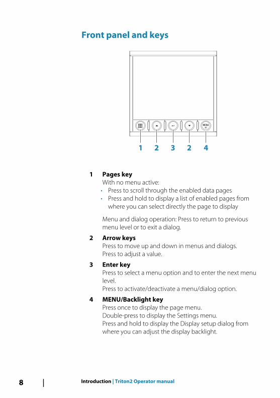
Front panel and keys
1 2 3 2 4
1 Pages keyWith no menu active:
• Press to scroll through the enabled data pages• Press and hold to display a list of enabled pages from
where you can select directly the page to display
Menu and dialog operation: Press to return to previousmenu level or to exit a dialog.
2 Arrow keysPress to move up and down in menus and dialogs.Press to adjust a value.
3 Enter keyPress to select a menu option and to enter the next menulevel.Press to activate/deactivate a menu/dialog option.
4 MENU/Backlight keyPress once to display the page menu.Double-press to display the Settings menu.Press and hold to display the Display setup dialog fromwhere you can adjust the display backlight.
8 Introduction | Triton2 Operator manual
Basic operation
Turning the unit on and offThe unit has no power key, and it will be running as long as power isconnected to the NMEA 2000 network backbone.
First time startupWhen the unit is started for the first time and after a factory reset,the unit displays a setup wizard. Respond to the setup wizardprompts to select some fundamental setup options. These settingscan later be changed and further configuration made as describedin "Software setup" on page 60.
Sleep modeIn Sleep mode, the backlight for screen and keys are turned off tosave power. The system continues to run in the background.
You select Sleep mode from the Display setup dialog, activated bypressing and holding the MENU key. Switch from Sleep mode tonormal operation by a short press on the MENU key.
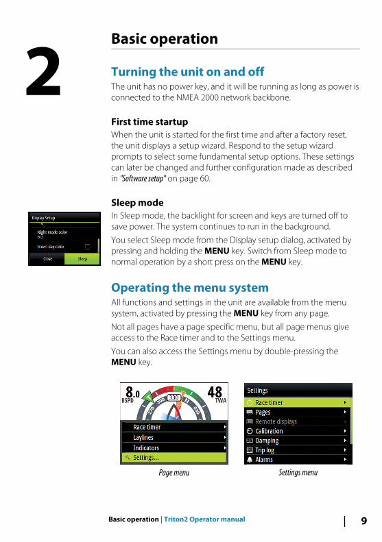
Operating the menu systemAll functions and settings in the unit are available from the menusystem, activated by pressing the MENU key from any page.
Not all pages have a page specific menu, but all page menus giveaccess to the Race timer and to the Settings menu.
You can also access the Settings menu by double-pressing theMENU key.
Page menu Settings menu
2
Basic operation | Triton2 Operator manual 9
• Use the arrow keys to move up and down in the menus and inthe dialogs
• Confirm a selection by pressing the Enter key• Return to previous menu level by pressing the Pages key
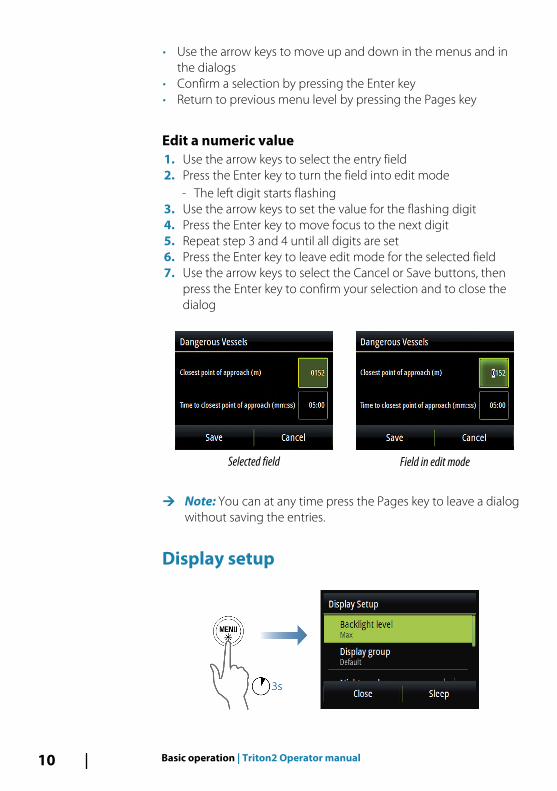
Edit a numeric value1. Use the arrow keys to select the entry field2. Press the Enter key to turn the field into edit mode
- The left digit starts flashing3. Use the arrow keys to set the value for the flashing digit4. Press the Enter key to move focus to the next digit5. Repeat step 3 and 4 until all digits are set6. Press the Enter key to leave edit mode for the selected field7. Use the arrow keys to select the Cancel or Save buttons, then
press the Enter key to confirm your selection and to close thedialog
Selected field Field in edit mode
Ú Note: You can at any time press the Pages key to leave a dialogwithout saving the entries.
Display setup
10 Basic operation | Triton2 Operator manual
The display setup can be adjusted at any time from the Displaysetup dialog, activated by pressing and holding the MENU key.
The following options are available:
• Backlight level: Adjusts the backlight level from Min (10%) to Max(100%) in 10% increments
- When the Backlight level field is active, subsequent presses onthe MENU key adjusts backlight level in decrements of 30%
• Display group: Defines which network group the unit belongs to
• Night mode: Activates/deactivates the night mode color palette
• Night mode color: Sets the night mode color palette
• Invert day color: Changes the background color for the pagesfrom default white to black
• Sleep: Turns the backlight for screen and keys off to save power
Ú Note: All changes made to the display setup will apply to allunits belonging to the same display group. For moreinformation about network groups, refer to "Network groups" onpage 72.
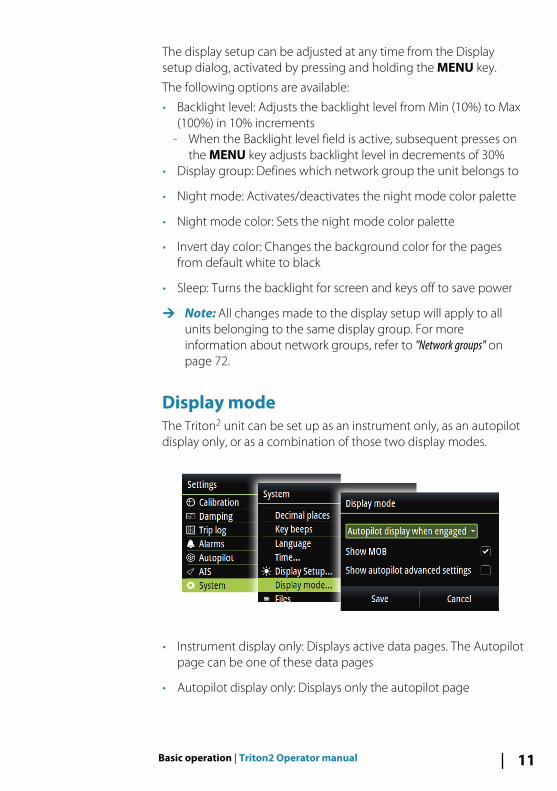
Display mode The Triton2 unit can be set up as an instrument only, as an autopilotdisplay only, or as a combination of those two display modes.
• Instrument display only: Displays active data pages. The Autopilotpage can be one of these data pages
• Autopilot display only: Displays only the autopilot page
Basic operation | Triton2 Operator manual 11
• Autopilot display when engaged: Switches automatically to theAutopilot page when the autopilot is switched to an automaticmode. When the autopilot is switched to Standby mode thedisplay switches back to the previous page. This behaviour doesnot require that an Autopilot page is selected as one of the 8enabled data pages
The Display mode dialog has the following additional options:
• Show MOB: Switches automatically to the MOB page if a ManOver Board event is triggered from another system on thenetwork. Refer to "Man Over Board (MOB)" on page 13
• Show autopilot advanced settings: Displays all available autopilotsettings. Refer to "Sailing (H5000)" on page 50.
Selecting a data pageThe Triton2 includes 16 predefined data pages, but only 8 of thesecan be enabled.
For detailed information about pages, refer to "Pages" on page 15.
Two options are available for selecting an enabled page:
• Directly selecting a page• Scrolling pages
For automatic page scrolling, refer to "Automatic scrolling pages" on page15.
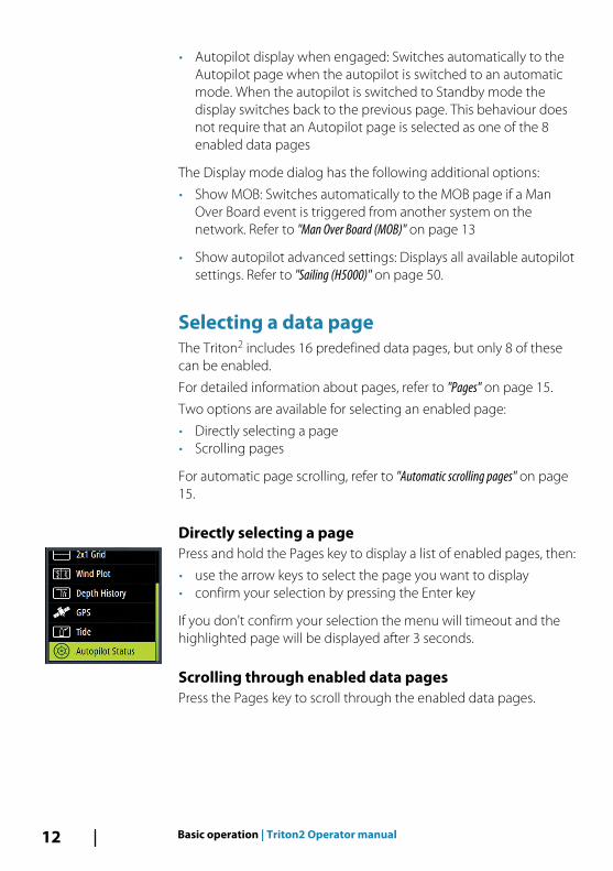
Directly selecting a pagePress and hold the Pages key to display a list of enabled pages, then:
• use the arrow keys to select the page you want to display• confirm your selection by pressing the Enter key
If you don't confirm your selection the menu will timeout and thehighlighted page will be displayed after 3 seconds.
Scrolling through enabled data pagesPress the Pages key to scroll through the enabled data pages.
12 Basic operation | Triton2 Operator manual
Man Over Board (MOB)Ú Note: MOB and AIS-SART will only work with a B&G
Multifunction Display (MFD) on the network.
If a Man Over Board event is triggered from another system on thenetwork, the instrument automatically switches to the MOB page.
This function can be enabled/disabled from the Display setupdialog. Refer to "Display mode" on page 11.
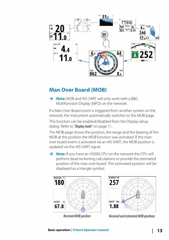
The MOB page shows the position, the range and the bearing of theMOB at the position the MOB function was activated. If the manover board event is activated via an AIS-SART, the MOB position isupdated via the AIS-SART signal.
Ú Note: If you have an H5000 CPU on the network the CPU willperform dead reckoning calculations to provide the estimatedposition of the man over board. This estimated position will bedisplayed as a triangle symbol.
Received MOB position Received and estimated MOB positions
Basic operation | Triton2 Operator manual 13

The system continues to display navigational information towardsthe MOB waypoint until you cancel the navigation from the menu.
14 Basic operation | Triton2 Operator manual

PagesThe Triton2 includes 16 predefined data pages.
In addition to these pages there are 13 template pages that can beused for creating user defined pages.
You can have up to 8 pages enabled in the unit. These can be anycombination of predefined pages and user defined pages.
Enabling/disabling a pageTo make a page available via the Page key you need to ensure it hasbeen selected as one of the eight enabled pages.
Automatic scrolling pagesYou can select to let the system automatically scroll through allenabled pages at a defined time interval.
You set the time interval and start the automatic scrolling functionfrom the Pages menu.
3
Pages | Triton2 Operator manual 15

Predefined pages and template pages
Pre-defined pages Template pages
Autopilot status 000.0 Full screen
Sailsteer 2x1 Grid
Highway 2x2 Grid
Laylines 2x2 Grid Offset
Wind plot 3x3 Grid
Tide 1 + 3 Digital - bottom
Weather 1 + 6 Digital
ft Depth history 1 + 3 Digital - side
Basic Speed & Depth 1 + 4 Digital
Basic Wind angle &Speed
Single analog
GPS Analog + 3
Composite wind Composite Wind + 3
AIS SailSteer + 3
Steering
Single Time plot
Dual Time plot
16 Pages | Triton2 Operator manual
Autopilot status pageAutopilot status. Refer to "Autopilot" on page 38.
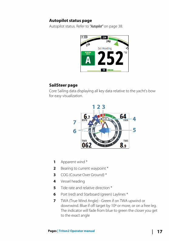
SailSteer pageCore Sailing data displaying all key data relative to the yacht's bowfor easy visualization.
1 Apparent wind *
2 Bearing to current waypoint *
3 COG (Course Over Ground) *
4 Vessel heading
5 Tide rate and relative direction *
6 Port (red) and Starboard (green) Laylines *
7 TWA (True Wind Angle) - Green if on TWA upwind ordownwind. Blue if off target by 10º or more, or on a free leg.The indicator will fade from blue to green the closer you getto the exact angle
Pages | Triton2 Operator manual 17

* Optional page items.
The following options are available from the menu for configuringthe SailSteer page:
Laylines• Tidal flow correction: Calculates the tidal flow and offsets the
laylines accordingly
• Target wind angle: Used for selecting the available target windangle options:
- Polar: Takes the target wind angle from the active polar table- Actual: Takes the instantaneous wind angle- Manual: Used for manually entering the upwind and
downwind values
• Layline limits: Shaded areas indicating the minimum andmaximum tack/gybe time period to either side of the layline. Thiscan be set to 5, 10, 15 or 30 minute increments.
IndicatorsDefines which indicators are displayed on the SailSteer page.
18 Pages | Triton2 Operator manual
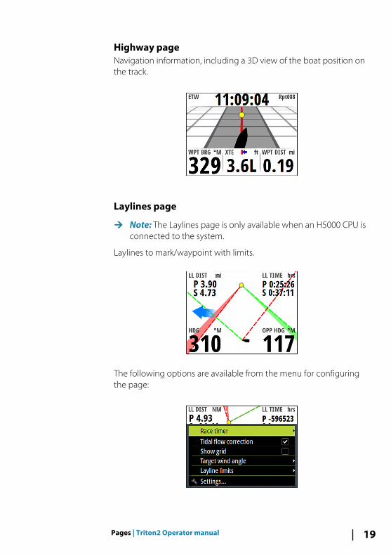
Highway pageNavigation information, including a 3D view of the boat position onthe track.
Laylines page
Ú Note: The Laylines page is only available when an H5000 CPU isconnected to the system.
Laylines to mark/waypoint with limits.
The following options are available from the menu for configuringthe page:
Pages | Triton2 Operator manual 19

Tidal flow correctionCalculates the tidal flow and offsets the laylines accordingly.
Show gridShows a grid with each square representing one boat length.
Target wind angleTrue wind angle is used in the layline calculations. There are 3options available:
• Polar: Takes the target wind angle from your polar table in theH5000 CPU
• Actual: Takes the current value of target wind angle• Manual: Allows for manually entering upwind and downwind
values
Layline limitsWhen selected will show a shaded area indicating the minimumand maximum tack/gybe time period either side of the layline. Thiscan be set to 5, 10, 15 & 30 minute increments.
Wind PlotTrue wind direction (TWD) and true wind speed (TWS) as a plottedgraph over a specified timescale.
20 Pages | Triton2 Operator manual
The Wind histogram time period can be set to show 5, 10, 30 or a 60minutes history.
You change the period from the menu or by using the arrow keys.
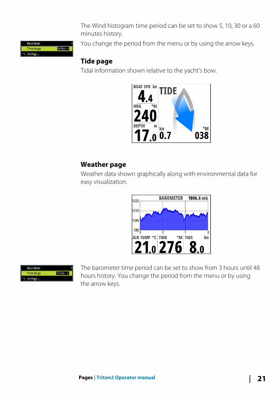
Tide pageTidal information shown relative to the yacht's bow.
Weather pageWeather data shown graphically along with environmental data foreasy visualization.
The barometer time period can be set to show from 3 hours until 48hours history. You change the period from the menu or by usingthe arrow keys.
Pages | Triton2 Operator manual 21
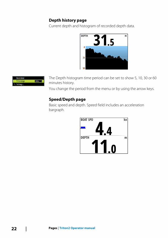
Depth history pageCurrent depth and histogram of recorded depth data.
The Depth histogram time period can be set to show 5, 10, 30 or 60minutes history.
You change the period from the menu or by using the arrow keys.
Speed/Depth pageBasic speed and depth. Speed field includes an accelerationbargraph.
22 Pages | Triton2 Operator manual

Wind Angle speed pageApparent angle and true wind speed.
The wind angle indicator (1) is red for port and green for starboardtack. The true wind speed field includes a Beaufort scale indicator(2).
GPS pageGPS and navigation information. If not navigating the navigationfields show dashes.
Pages | Triton2 Operator manual 23
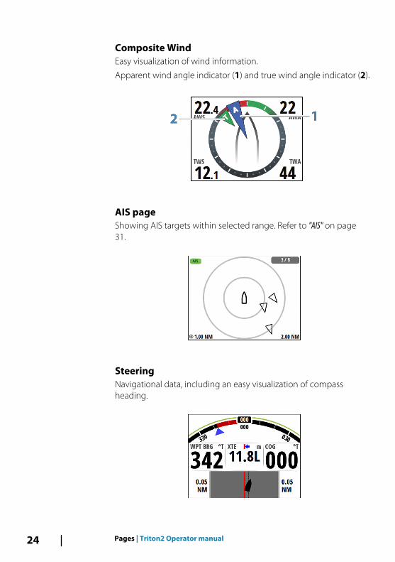
Composite WindEasy visualization of wind information.
Apparent wind angle indicator (1) and true wind angle indicator (2).
AIS pageShowing AIS targets within selected range. Refer to "AIS" on page31.
SteeringNavigational data, including an easy visualization of compassheading.
24 Pages | Triton2 Operator manual
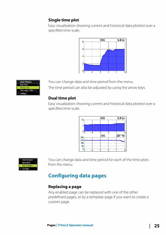
Single time plotEasy visualization showing current and historical data plotted over aspecified time scale.
You can change data and time period from the menu.
The time period can also be adjusted by using the arrow keys.
Dual time plotEasy visualization showing current and historical data plotted over aspecified time scale.
You can change data and time period for each of the time plotsfrom the menu.
Configuring data pages
Replacing a pageAny enabled page can be replaced with one of the otherpredefined pages, or by a template page if you want to create acustom page.
Pages | Triton2 Operator manual 25
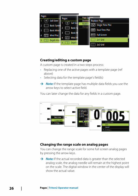
Creating/editing a custom pageA custom page is created in a two steps process:
• Replacing one of the active pages with a template page (refabove)
• Selecting data for the template page's field(s)
Ú Note: If the template page has multiple data fields you use thearrow keys to select active field.
You can later change the data for any fields in a custom page.
Changing the range scale on analog pagesYou can change the range scale for some full screen analog pagesby pressing the arrow keys.
Ú Note: If the actual recorded data is greater than the selectedanalog scale, the analog needle will remain at the highest pointon the scale. The digital window in the center of the display willshow the actual value.
26 Pages | Triton2 Operator manual

Missing or faulty dataIf a data type is missing or if the data is out of scale, there will be nodata reading on the display.
The example shows the basic Depth/Speed page with missingspeed information.
Pages | Triton2 Operator manual 27

Race timer and Trip logThe Race timer and the Trip log are available from the Settingsmenu.
Race timer and Trip log are temporary pages, and you cannotconfigure these views as one of the user defined pages.
The Race timer and the Trip log remains on the screen until youpress the Pages key.
Race timerThe race timer can be used to countdown to zero from a specifiedtime, ideal for counting down to a race start. It can also be used tocount up from zero to record the elapsed time.
Ú Note: The race timer is by default shared between all displayson the network. All timer values are synchronized.
When the Race timer is running, you can stop and you cansynchronize the timer (up or down to the nearest full minute) fromany page menu, activated by pressing the MENU key.
When the Race timer is stopped, the following options are availablefrom the page menu:
4
28 Race timer and Trip log | Triton2 Operator manual
StartStarts the Race timer. If the timer was stopped and not reset, thetimer will continue counting from the time it had when it wasstopped.
ResetResets the Race timer to the start value.
Rolling timerRestarts the countdown timer every time it reaches zero. It willcontinue to do this until the timer is stopped or until this option isde-selected.
Auto start tripEnables the Trip log to record time and mileage from the momentthe countdown timer begins counting up from zero.
Set start valueTo count down to a race start, a time value can be set in the Set startvalue field.
When a time is present in the start value field the Race timer willbegin to count down from that number when the timer is started.Once the time reaches zero it will begin counting up recording theelapsed time.
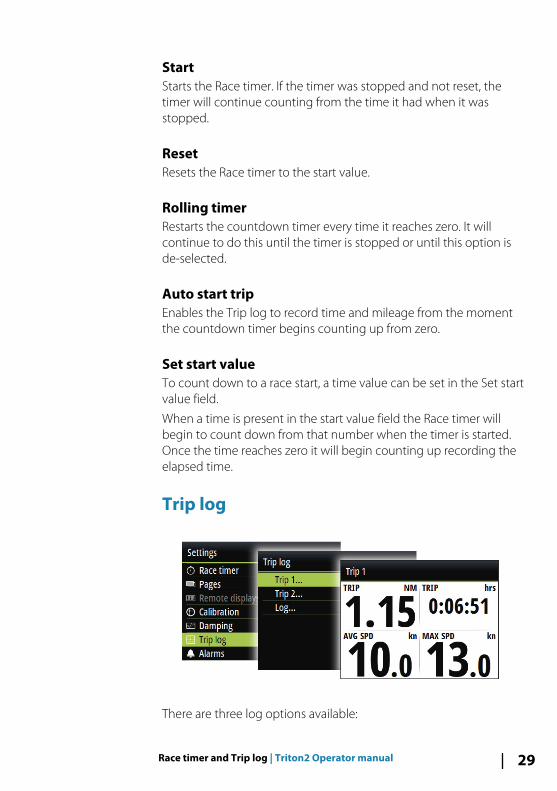
Trip log
There are three log options available:
Race timer and Trip log | Triton2 Operator manual 29
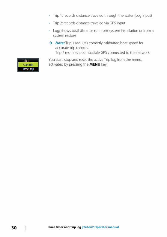
• Trip 1: records distance traveled through the water (Log input)
• Trip 2: records distance traveled via GPS input
• Log: shows total distance run from system installation or from asystem restore
Ú Note: Trip 1 requires correctly calibrated boat speed foraccurate trip records.Trip 2 requires a compatible GPS connected to the network.
You start, stop and reset the active Trip log from the menu,activated by pressing the MENU key.
30 Race timer and Trip log | Triton2 Operator manual
AISIf a compatible AIS system or an NMEA 2000 VHF that can do AIS(Automatic Identification System) is connected to the network, thenany targets detected by these devices can be displayed on the AISpage. You can also see messages and position from SARTs andAtoNs within the defined range.
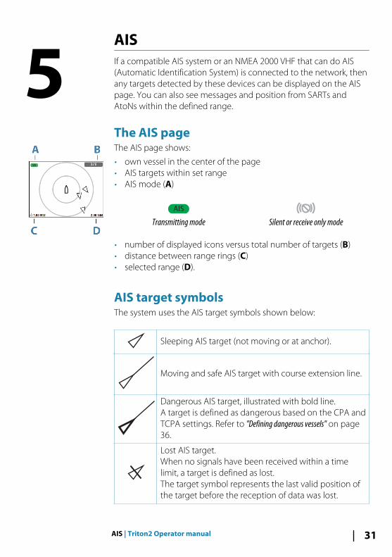
The AIS pageThe AIS page shows:
• own vessel in the center of the page• AIS targets within set range• AIS mode (A)
AIS
Transmitting mode Silent or receive only mode
• number of displayed icons versus total number of targets (B)• distance between range rings (C)• selected range (D).
AIS target symbolsThe system uses the AIS target symbols shown below:
Sleeping AIS target (not moving or at anchor).
Moving and safe AIS target with course extension line.
Dangerous AIS target, illustrated with bold line.A target is defined as dangerous based on the CPA andTCPA settings. Refer to "Defining dangerous vessels" on page36.
Lost AIS target.When no signals have been received within a timelimit, a target is defined as lost.The target symbol represents the last valid position ofthe target before the reception of data was lost.
5
AIS | Triton2 Operator manual 31

Selected AIS target, activated by selecting a targetsymbol.The target returns to the default target symbol whenthe cursor is removed from the symbol.
AIS SART (AIS Search And Rescue Transmitter).
Selecting a targetYou use the arrow keys to select individual AIS targets on the AISpage. When selected the target symbol change to a selected AIStarget symbol.
AIS page display optionsThe following options are available for displaying the AIS targets:
RangeDefines the display range on the AIS page. Selected range isindicated in the lower right corner of the AIS page.
Icon filtersBy default, all targets within the selected range are shown on theAIS page. You can select to hide safe AIS vessels, and to not showtargets based on vessel speed.
Extension linesDefines the length of course over ground and heading extensionlines for your own vessel and for other vessels.
The length of the extension lines is set to indicate the distance thevessel will move in the selected time period.
Your own vessel heading information is read from the activeheading sensor, and COG information is received from the activeGPS. For other vessels COG data is included in the message receivedfrom the AIS system.
32 AIS | Triton2 Operator manual
Displaying target information
Displaying information for a single targetWhen a target is selected, you press the Enter key to display detailedinformation about the selected target.
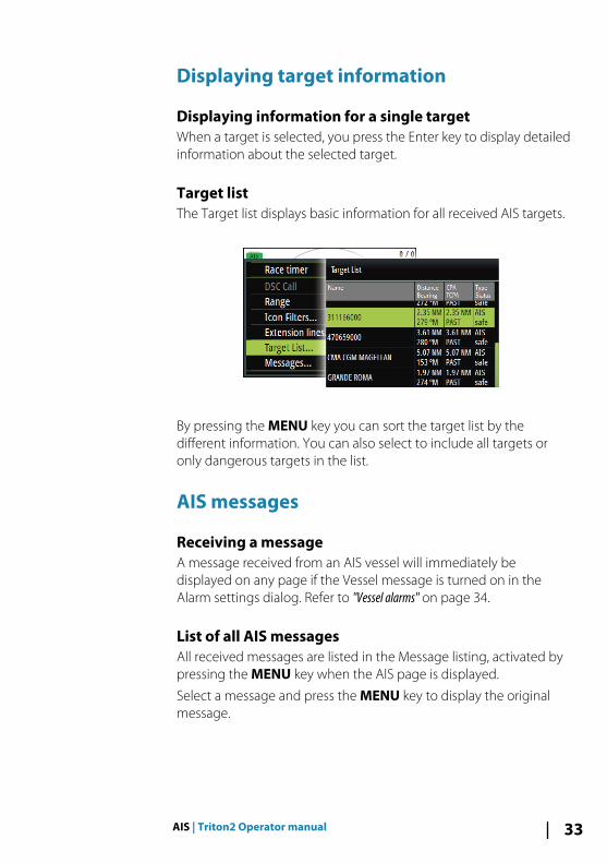
Target listThe Target list displays basic information for all received AIS targets.
By pressing the MENU key you can sort the target list by thedifferent information. You can also select to include all targets oronly dangerous targets in the list.
AIS messages
Receiving a messageA message received from an AIS vessel will immediately bedisplayed on any page if the Vessel message is turned on in theAlarm settings dialog. Refer to "Vessel alarms" on page 34.
List of all AIS messagesAll received messages are listed in the Message listing, activated bypressing the MENU key when the AIS page is displayed.
Select a message and press the MENU key to display the originalmessage.
AIS | Triton2 Operator manual 33
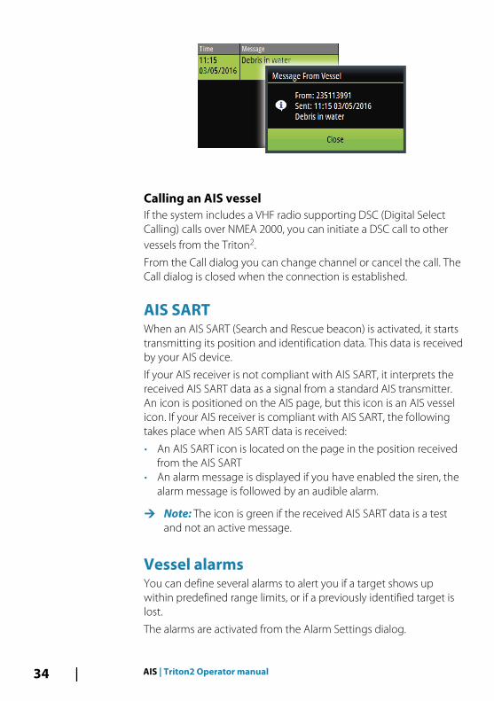
Calling an AIS vesselIf the system includes a VHF radio supporting DSC (Digital SelectCalling) calls over NMEA 2000, you can initiate a DSC call to othervessels from the Triton2.
From the Call dialog you can change channel or cancel the call. TheCall dialog is closed when the connection is established.
AIS SARTWhen an AIS SART (Search and Rescue beacon) is activated, it startstransmitting its position and identification data. This data is receivedby your AIS device.
If your AIS receiver is not compliant with AIS SART, it interprets thereceived AIS SART data as a signal from a standard AIS transmitter.An icon is positioned on the AIS page, but this icon is an AIS vesselicon. If your AIS receiver is compliant with AIS SART, the followingtakes place when AIS SART data is received:
• An AIS SART icon is located on the page in the position receivedfrom the AIS SART
• An alarm message is displayed if you have enabled the siren, thealarm message is followed by an audible alarm.
Ú Note: The icon is green if the received AIS SART data is a testand not an active message.
Vessel alarmsYou can define several alarms to alert you if a target shows upwithin predefined range limits, or if a previously identified target islost.
The alarms are activated from the Alarm Settings dialog.
34 AIS | Triton2 Operator manual

For more information about alarms, refer to "Alarms" on page 57.
Dangerous vesselControls whether an alarm will be activated when a vessel comescloser than the distance for CPA within the time limit for TCPA. Referto "Defining dangerous vessels" on page 36.
AIS vessel lostSets the range for lost vessels. If a vessel is lost within the set range,an alarm occurs.
Ú Note: The check box controls whether the alarm pop-up box isdisplayed and if the siren goes on. The CPA and TCPA definewhen a vessel is dangerous regardless of the enabled ordisabled state.
Vessel messageControls whether an alarm will be activated when a message isreceived from an AIS target.
AIS | Triton2 Operator manual 35
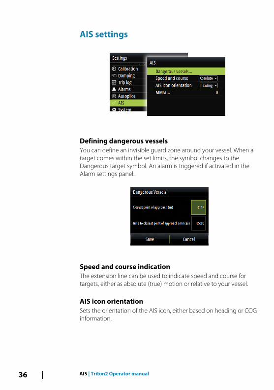
AIS settings
Defining dangerous vesselsYou can define an invisible guard zone around your vessel. When atarget comes within the set limits, the symbol changes to theDangerous target symbol. An alarm is triggered if activated in theAlarm settings panel.
Speed and course indicationThe extension line can be used to indicate speed and course fortargets, either as absolute (true) motion or relative to your vessel.
AIS icon orientationSets the orientation of the AIS icon, either based on heading or COGinformation.
36 AIS | Triton2 Operator manual
Your vessel's MMSI numberUsed for entering your own MMSI (Maritime Mobile Service Identity)number into the system. You need to have this number entered toreceive addressed messages from AIS and DSC vessels.
AIS | Triton2 Operator manual 37

AutopilotIf a compatible autopilot computer is connected to the system,autopilot functionality is available in the system.
The system does not allow for more than one autopilot computeron the network.
The display unit automatically detects the autopilot computeravailable on the network and presents settings, configuration anduser options for the connected computer.
For details about installing and configuring an autopilot computer,refer to the separate manuals that come with the autopilotcomputer.
Safe operation with the autopilot
Warning: An autopilot is a useful navigational aid,but DOES NOT replace a human navigator.
Warning: Ensure the autopilot has been installedcorrectly, commissioned and calibrated before use.
Ú Note: You can disengage the autopilot at any time by pressingthe STBY key on the Triton2 Pilot controller.
Do not use automatic steering when:
• In heavy traffic areas or in narrow waters• In poor visibility or extreme sea conditions• When in areas where use of an autopilot is prohibited by law
When using an autopilot:
• Do not leave the helm unattended• Do not place any magnetic material or equipment near the
heading sensor used by the autopilot system• Verify at regular intervals the course and position of the vessel• Always switch to Standby mode and reduce speed in due time to
avoid hazardous situations
6
38 Autopilot | Triton2 Operator manual
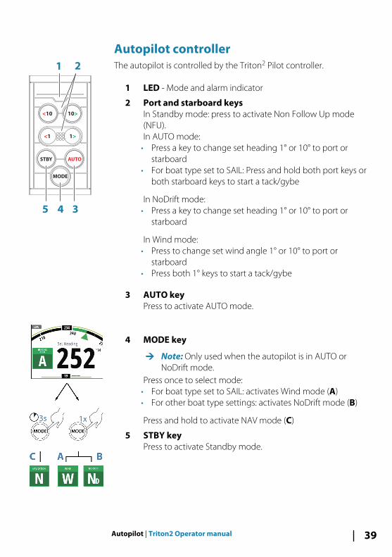
Autopilot controllerThe autopilot is controlled by the Triton2 Pilot controller.
1 LED - Mode and alarm indicator
2 Port and starboard keysIn Standby mode: press to activate Non Follow Up mode(NFU).In AUTO mode:
• Press a key to change set heading 1° or 10° to port orstarboard
• For boat type set to SAIL: Press and hold both port keys orboth starboard keys to start a tack/gybe
In NoDrift mode:• Press a key to change set heading 1° or 10° to port or
starboard
In Wind mode:• Press to change set wind angle 1° or 10° to port or
starboard• Press both 1° keys to start a tack/gybe
3 AUTO keyPress to activate AUTO mode.
4 MODE key
Ú Note: Only used when the autopilot is in AUTO orNoDrift mode.
Press once to select mode:• For boat type set to SAIL: activates Wind mode (A)• For other boat type settings: activates NoDrift mode (B)
Press and hold to activate NAV mode (C)
5 STBY keyPress to activate Standby mode.
<10 10>
<1 1>
STBY AUTO
MODE
1 2
35 4
Autopilot | Triton2 Operator manual 39
Mode and alarm indicationThe LED in the Autopilot controller indicates active mode and alarmby the flashing:
• AUTO mode: solid light• Wind mode: flashing (80% on, 20% off)• NAV mode; flashing (40% on, 60% off)• Alarm on the network: rapid flashing
The LED is green in Day mode and red in Night mode
Ú Note: There is no LED indication for NoDrift and Non-Followmodes.
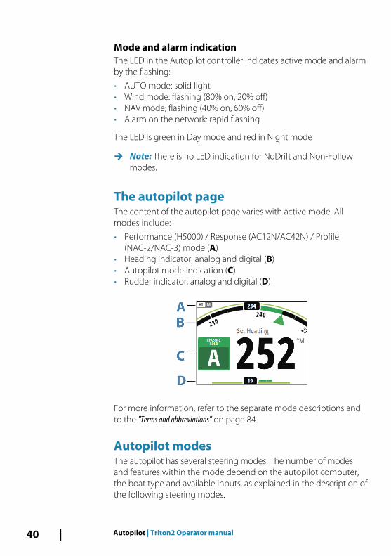
The autopilot pageThe content of the autopilot page varies with active mode. Allmodes include:
• Performance (H5000) / Response (AC12N/AC42N) / Profile(NAC-2/NAC-3) mode (A)
• Heading indicator, analog and digital (B)• Autopilot mode indication (C)• Rudder indicator, analog and digital (D)
For more information, refer to the separate mode descriptions andto the "Terms and abbreviations" on page 84.
Autopilot modes The autopilot has several steering modes. The number of modesand features within the mode depend on the autopilot computer,the boat type and available inputs, as explained in the description ofthe following steering modes.
40 Autopilot | Triton2 Operator manual

Standby modeStandby mode is used when you steer the boat at the helm.
• Switch to Standby mode by pressing the STBY key.
Ú Note: If you press one of the port or starboard keys while inStandby mode, the autopilot will switch to Non-Follow Upmode.
Non-Follow Up (NFU) modeIn NFU mode you can use the port and starboard keys on thecontroller to operate the rudder. The rudder will move as long asthe key is pressed.
• Switch to NFU mode by pressing one of the port or starboardkeys when the autopilot is in Standby mode.
AUTO mode (Heading hold)In AUTO mode the autopilot issues rudder commands required tosteer the vessel automatically on a set heading. In this mode theautopilot does not compensate for any drifting caused by currentand/or wind (A).
A
• Switch to AUTO mode by pressing the AUTO key. When themode is activated, the autopilot selects the current boat headingas the set heading.
Changing set heading in AUTO modeYou adjust the set heading by using the port or starboard keys.
Autopilot | Triton2 Operator manual 41

An immediate heading change takes place. The new heading ismaintained until a new heading is set.
Tacking and Gybing in AUTO modeTacking and Gybing in AUTO mode uses the heading as reference.The tacking/gybing operation changes the set heading to port orstarboard with a fixed angle.
The tacking parameters are set in the Setup/Sailing parameters: TheTack angle defines the tacking angle, while the Tack time definesthe rate of turn during the tack/gybe. Refer to "Autopilot settings" onpage 47:
• Initiate the Tack or Gybe function to port or starboard by pressingand holding both port keys or both starboard keys on theautopilot controller.
- The turn is started immediately to the direction selected by thekeys.
Wind mode
Ú Note: Wind mode is only available when the boat type is set toSAIL. It is not possible to activate wind mode if windinformation is missing.
When wind mode is engaged, the autopilot captures the currentwind angle as steering reference, and adjusts the heading of theboat to maintain this wind angle.
Prior to entering wind mode the autopilot system must beoperating in AUTO mode and with valid input from the windtransducer.
• Switch to Wind mode by pressing the MODE key when theautopilot is in AUTO mode.
The autopilot will now keep the boat on the set wind angle until anew mode is selected or a new wind angle is set.
Warning: In wind mode the autopilot steers to theapparent or true wind angle and not to a compassheading. Any wind shift could result in the vesselsteering on an undesired course.
<10 10>
<1 1>1>
42 Autopilot | Triton2 Operator manual
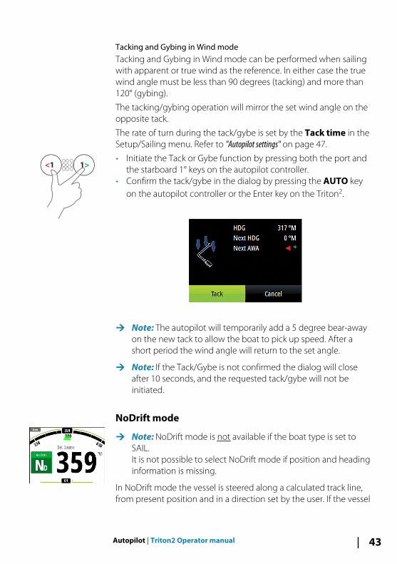
Tacking and Gybing in Wind modeTacking and Gybing in Wind mode can be performed when sailingwith apparent or true wind as the reference. In either case the truewind angle must be less than 90 degrees (tacking) and more than120° (gybing).
The tacking/gybing operation will mirror the set wind angle on theopposite tack.
The rate of turn during the tack/gybe is set by the Tack time in theSetup/Sailing menu. Refer to "Autopilot settings" on page 47.
• Initiate the Tack or Gybe function by pressing both the port andthe starboard 1° keys on the autopilot controller.
• Confirm the tack/gybe in the dialog by pressing the AUTO keyon the autopilot controller or the Enter key on the Triton2.
Ú Note: The autopilot will temporarily add a 5 degree bear-awayon the new tack to allow the boat to pick up speed. After ashort period the wind angle will return to the set angle.
Ú Note: If the Tack/Gybe is not confirmed the dialog will closeafter 10 seconds, and the requested tack/gybe will not beinitiated.
NoDrift mode
Ú Note: NoDrift mode is not available if the boat type is set toSAIL.It is not possible to select NoDrift mode if position and headinginformation is missing.
In NoDrift mode the vessel is steered along a calculated track line,from present position and in a direction set by the user. If the vessel
<1 1>
Autopilot | Triton2 Operator manual 43
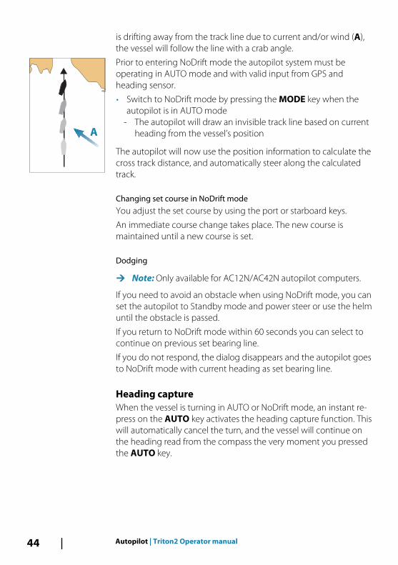
is drifting away from the track line due to current and/or wind (A),the vessel will follow the line with a crab angle.
Prior to entering NoDrift mode the autopilot system must beoperating in AUTO mode and with valid input from GPS andheading sensor.
• Switch to NoDrift mode by pressing the MODE key when theautopilot is in AUTO mode
- The autopilot will draw an invisible track line based on currentheading from the vessel’s position
The autopilot will now use the position information to calculate thecross track distance, and automatically steer along the calculatedtrack.
Changing set course in NoDrift modeYou adjust the set course by using the port or starboard keys.
An immediate course change takes place. The new course ismaintained until a new course is set.
Dodging
Ú Note: Only available for AC12N/AC42N autopilot computers.
If you need to avoid an obstacle when using NoDrift mode, you canset the autopilot to Standby mode and power steer or use the helmuntil the obstacle is passed.
If you return to NoDrift mode within 60 seconds you can select tocontinue on previous set bearing line.
If you do not respond, the dialog disappears and the autopilot goesto NoDrift mode with current heading as set bearing line.
Heading captureWhen the vessel is turning in AUTO or NoDrift mode, an instant re-press on the AUTO key activates the heading capture function. Thiswill automatically cancel the turn, and the vessel will continue onthe heading read from the compass the very moment you pressedthe AUTO key.
A
44 Autopilot | Triton2 Operator manual
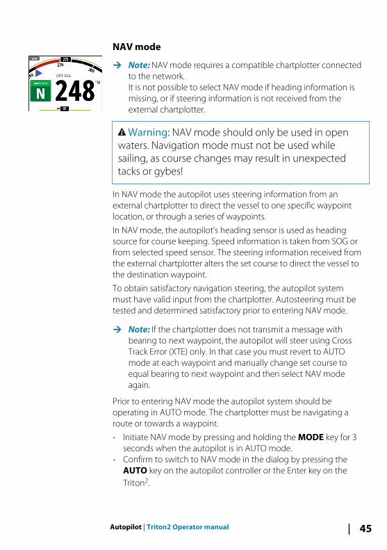
NAV mode
Ú Note: NAV mode requires a compatible chartplotter connectedto the network.It is not possible to select NAV mode if heading information ismissing, or if steering information is not received from theexternal chartplotter.
Warning: NAV mode should only be used in openwaters. Navigation mode must not be used whilesailing, as course changes may result in unexpectedtacks or gybes!
In NAV mode the autopilot uses steering information from anexternal chartplotter to direct the vessel to one specific waypointlocation, or through a series of waypoints.
In NAV mode, the autopilot's heading sensor is used as headingsource for course keeping. Speed information is taken from SOG orfrom selected speed sensor. The steering information received fromthe external chartplotter alters the set course to direct the vessel tothe destination waypoint.
To obtain satisfactory navigation steering, the autopilot systemmust have valid input from the chartplotter. Autosteering must betested and determined satisfactory prior to entering NAV mode.
Ú Note: If the chartplotter does not transmit a message withbearing to next waypoint, the autopilot will steer using CrossTrack Error (XTE) only. In that case you must revert to AUTOmode at each waypoint and manually change set course toequal bearing to next waypoint and then select NAV modeagain.
Prior to entering NAV mode the autopilot system should beoperating in AUTO mode. The chartplotter must be navigating aroute or towards a waypoint.
• Initiate NAV mode by pressing and holding the MODE key for 3seconds when the autopilot is in AUTO mode.
• Confirm to switch to NAV mode in the dialog by pressing theAUTO key on the autopilot controller or the Enter key on theTriton2.
Autopilot | Triton2 Operator manual 45

Turning in NAV modeWhen your vessel reaches a waypoint, the autopilot will give anaudible warning and display a dialog with the new courseinformation.
There is a user defined limit for the allowed automatic coursechange to next waypoint in a route. If the course change is morethan this set limit, you are prompted to verify that the upcomingcourse change is acceptable.
• If the required course change to the next waypoint is less thanthe course change limit, the autopilot will automatically changethe course. The dialog will disappear after 8 seconds unlesscleared by the Pages key.
• If the required course change to next waypoint is more than theset limit, you are prompted to verify that the upcoming coursechange is acceptable. If the turn is not accepted, the vessel willcontinue with the current set heading.
Course change less than set limit Course change larger than set limit
The course change limit setting depends on the autopilotcomputer:
• H5000: Fixed value (30°)
46 Autopilot | Triton2 Operator manual
• NAC-2/NAC-3: Course chg confirm angle, refer to "Steering (NAC-2/NAC-3)" on page 51
• AC12N/42N and SG05: Navigation change limit, refer to"Automatic steering (AC12N/AC42N)" on page 55
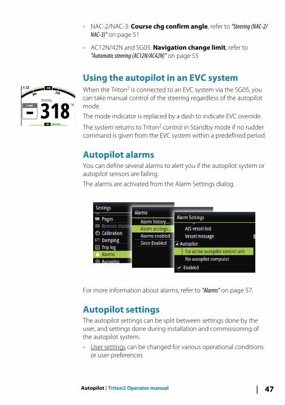
Using the autopilot in an EVC systemWhen the Triton2 is connected to an EVC system via the SG05, youcan take manual control of the steering regardless of the autopilotmode.
The mode indicator is replaced by a dash to indicate EVC override.
The system returns to Triton2 control in Standby mode if no ruddercommand is given from the EVC system within a predefined period.
Autopilot alarmsYou can define several alarms to alert you if the autopilot system orautopilot sensors are failing.
The alarms are activated from the Alarm Settings dialog.
For more information about alarms, refer to "Alarms" on page 57.
Autopilot settingsThe autopilot settings can be split between settings done by theuser, and settings done during installation and commissioning ofthe autopilot system.
• User settings can be changed for various operational conditionsor user preferences
Autopilot | Triton2 Operator manual 47
• Installation settings are defined during commissioning of theautopilot system. No changes should later be done to thesesettings
Both user settings and installation settings depends on whichautopilot computer that is connected to the system.
The following sections describe the settings that can be changed bythe user. The settings are described per autopilot computer.
Installation settings are available in the documentation followingthe autopilot computers.
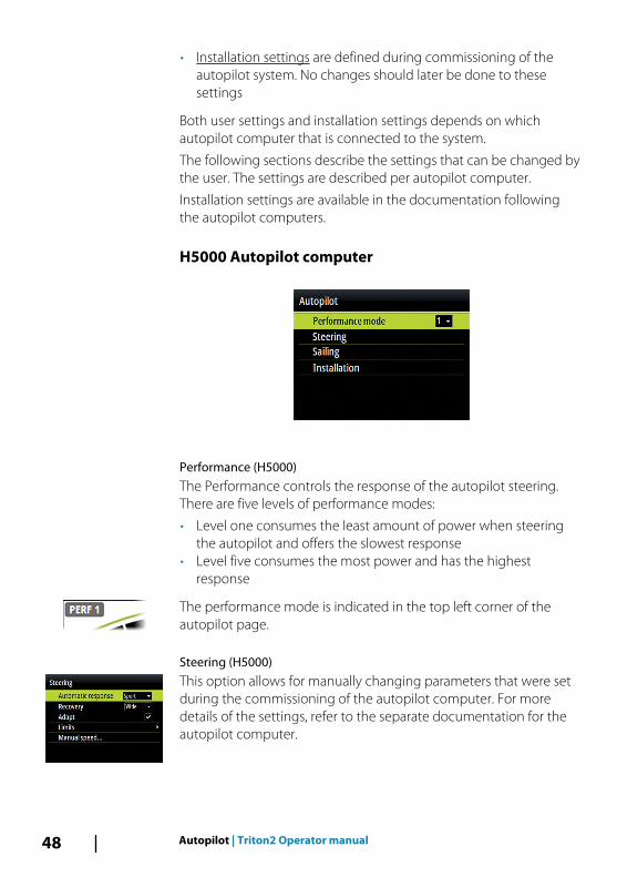
H5000 Autopilot computer
Performance (H5000)The Performance controls the response of the autopilot steering.There are five levels of performance modes:
• Level one consumes the least amount of power when steeringthe autopilot and offers the slowest response
• Level five consumes the most power and has the highestresponse
The performance mode is indicated in the top left corner of theautopilot page.
Steering (H5000)This option allows for manually changing parameters that were setduring the commissioning of the autopilot computer. For moredetails of the settings, refer to the separate documentation for theautopilot computer.
48 Autopilot | Triton2 Operator manual
• Automatic response: controls the rate that which the autopilotreacts to any environmental influences on the vessels desiredcourse
- Off: The autopilot will always remain in the response modeselected
- Economy: The autopilot will need to sense large environmentalchanges before increasing the response setting
- Normal: The autopilot will need to sense moderateenvironmental changes before increasing the responsesettings
- Sport: The autopilot will be most sensitive to changingconditions and will automatically increase its response rate tocounter environmental changes
• Recovery: Allows the user to set the sensitivity to course errorsand how the autopilot will react to unexpected events, forexample sudden wave or wind shifts. This function allows theautopilot to instantaneously increase the steering response to itsmaximum setting (Perf 5), and make a rapid recovery. TheRecovery will automatically switch off after 15 seconds or whenthe heading error has been corrected. The autopilot will thenresume the previous response setting and continue normaloperation.
- Off- Narrow: The autopilot is most sensitive to sudden course
changes corrected- Medium: The autopilot is configured to the medium value
when correcting sudden course changes- Wide: The autopilot is least sensitive to sudden course changes
• Adapt: Software feature that continues to adjust parameters thatare essential for the steering performance, e.g. speed, trim,draught and tide effects. When activated these parameters areoptimized during the voyage in response to the vessel'sbehavior.
- ON/OFF
• Limits: Allows control of the True Wind Angle range where Gustand True Wind Speed response can be configured and controlled
- TWA min: Minimum True Wind Angle that gust and True WindSpeed response operate in.
Autopilot | Triton2 Operator manual 49
- TWA max: Maximum True Wind Angle that gust and True WindSpeed response operate in.
- Bear away max: Maximum angle the vessel will bear awayduring stability control
- Cruising speed: The preferred cruising speed for this vessel(comfortable and economical)
- Rudder limit: Determines the maximum rudder movement indegrees from midship position that the autopilot cancommand the rudder in the automatic modes. The Rudderlimit setting is only active during autosteering on straightcourses, NOT during course changes. Rudder limit does notaffect Non-Follow-up steering.
- Off course: Defines the limit for the off course alarm
• Manual speed: If neither boat speed or SOG data is available andor deemed reliable a manual value for speed source can beentered and used by the autopilot to aid steering calculations
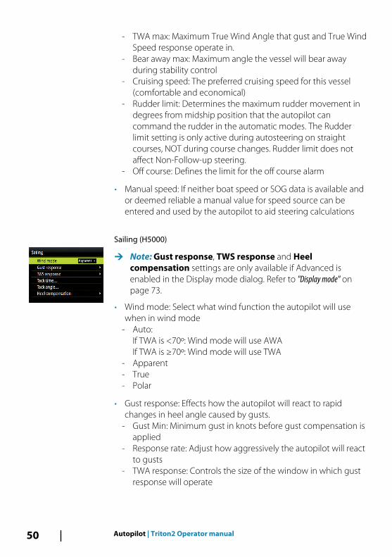
Sailing (H5000)
Ú Note: Gust response, TWS response and Heelcompensation settings are only available if Advanced isenabled in the Display mode dialog. Refer to "Display mode" onpage 73.
• Wind mode: Select what wind function the autopilot will usewhen in wind mode
- Auto:If TWA is <70º: Wind mode will use AWAIf TWA is ≥70º: Wind mode will use TWA
- Apparent- True- Polar
• Gust response: Effects how the autopilot will react to rapidchanges in heel angle caused by gusts.
- Gust Min: Minimum gust in knots before gust compensation isapplied
- Response rate: Adjust how aggressively the autopilot will reactto gusts
- TWA response: Controls the size of the window in which gustresponse will operate
50 Autopilot | Triton2 Operator manual

• TWS response (True Wind Speed): Used to compensate for longterm changes in wind speed. If the average wind speed increasesand stays high, the boat will bear away accordingly, and remainlow to the wind until the wind decreases
- Response rate: Set the rate of TWS response. 1 = slowestresponse, 10 = quickest response
• Tack angle: Controls the angle that the boat will tack to between50º - 150º in AUTO mode
• Tack time: Controls the rate of turn (tack time) when performinga tack in AUTO and Wind mode.
• Heel compensation: Provides protection against roll inducedbroaching in heavy seas or high gust conditions by applying thecorrect amount of rudder compensation before adverse eventsbecome dangerous.
- Response rate: Set the rate of heel compensation. 1 = slowestresponse, 10 = quickest response
NAC-2/NAC-3 Autopilot computer
Steering (NAC-2/NAC-3)This option allows for manually changing parameters that were setduring the commissioning of the autopilot computer. For moredetails of the settings, refer to the separate documentation for theautopilot computer.
• Low speed / High speed- Turn rate: The rate the vessel is turning in degrees per minute- Rudder gain: Ratio between the heading error and the
commanded angle
Autopilot | Triton2 Operator manual 51
- Counter rudder: Counteracts the effect of the vessel turn rateand inertia
- Autotrim: When the vessel has a constant heading error due toexternal forces such as wind and current, the Autotrim functioncorrects for this by building up a constant rudder offset. TheAutotrim value is reset every time the AUTO mode is enteredor when a course change greater than approximately 20° ismade. Auto trim is automatically disabled during a turn.
- Init rudder: Defines how the system moves the rudder whenswitching from power steering to an automatic mode.
• Center: Moves the rudder to zero position• Actual: Maintains the rudder offset
- Rudder limit: Determines the maximum rudder movement indegrees from midship position that the autopilot cancommand the rudder in the automatic modes. The Rudderlimit setting is only active during autosteering on straightcourses, NOT during course changes. Rudder limit does notaffect Non-Follow-up steering.
- Off heading limit: Sets the limit for the off heading alarm. Analarm occurs when the actual heading deviates from the setheading more than the selected limit.
- Track response: Defines how fast the autopilot shall respondafter having registered a cross track distance
- Track approach angle: Defines the angle used when the vesselis approaching a leg. This setting is used both when you startnavigating and when you use track offset.
- Course change confirm angle: Defines the limits for coursechange to next waypoint in a route. If the course change ismore than this set limit, you are prompted to verify that theupcoming course change is acceptable.
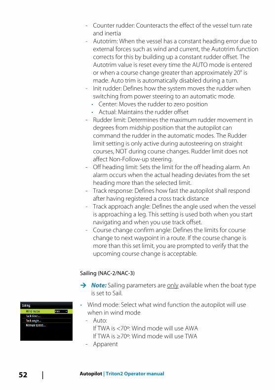
Sailing (NAC-2/NAC-3)
Ú Note: Sailing parameters are only available when the boat typeis set to Sail.
• Wind mode: Select what wind function the autopilot will usewhen in wind mode
- Auto:If TWA is <70º: Wind mode will use AWAIf TWA is ≥70º: Wind mode will use TWA
- Apparent
52 Autopilot | Triton2 Operator manual

- True
• Tack time: Controls the rate of turn (tack time) when performinga tack in wind mode.
• Tack angle: Controls the angle that the boat will tack to between50º - 150º in AUTO mode
• Manual speed: If neither boat speed or SOG data is available andor deemed reliable a manual value for speed source can beentered and used by the autopilot to aid steering calculations
AC12N/AC42N Autopilot computer
Response (AC12N/AC42N)The AC12N/42N includes three different sets of steering modes;High (HI), Low (LO) and Wind. The mode can be automatically ormanually selected.
The speed at which the autopilot automatically changes from LO toHI parameters (or opposite) is determined by the Transition speedsetting, defined during the commissioning of the autopilot. Refer tothe detailed description in the autopilot computer'sdocumentation.
You can manually fine tune each of the three response modes.Level 4 is default with parameter values as set by the autotunefunction. If no autotune is made (not recommended) the level 4values are the factory default values.
• A low response level reduces the rudder activity and provides amore “loose” steering
• A high response level increases the rudder activity and provides amore “tight” steering. A too high response level causes the boatto start lazy-s movements.
Autopilot | Triton2 Operator manual 53
The Wind response is used on sailboats
• Increase the Wind value if the difference between the set windangle and the actual wind angle is too big
• Decrease the Wind value if the actual wind angle is S-ing aroundthe set wind angle, or if the rudder activity is too high
The performance mode is indicated in the top left corner of theautopilot page.
• HI-A: High response mode set automatically• LO-A: Low response mode set automatically• HI-M: High response mode set manually• LO-M: Low response mode set manually
Ú Note: If no speed input is available the autopilot defaults to LOsteering parameters when engaging an automatic mode. This isa safety feature to prevent oversteering
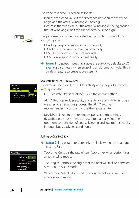
Sea state filter (AC12N/AC42N)This filter is used to reduce rudder activity and autopilot sensitivityin rough weather.
• OFF: Seastate filter is disabled. This is the default setting.
• AUTO: Reduces rudder activity and autopilot sensitivity in roughweather by an adaptive process. The AUTO setting isrecommended if you want to use the seastate filter.
• MANUAL: Linked to the steering response control settingsdescribed previously. It may be used to manually find theoptimum combination of course keeping and low rudder activityin rough but steady sea conditions.
Sailing (AC12N/AC42N)
Ú Note: Sailing parameters are only available when the boat typeis set to Sail.
• Tack time: Controls the rate of turn (tack time) when performinga tack in wind mode.
• Tack angle: Controls the angle that the boat will tack to between50º - 150º in AUTO mode
• Wind mode: Select what wind function the autopilot will usewhen in wind mode
54 Autopilot | Triton2 Operator manual
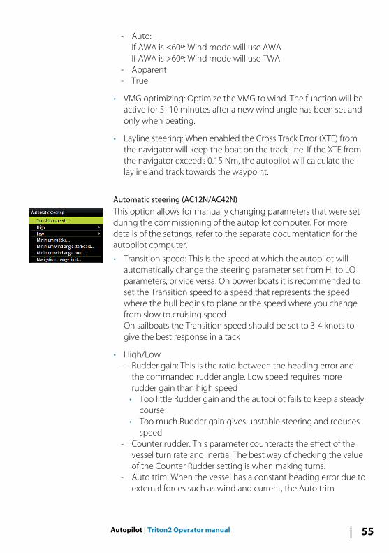
- Auto:If AWA is ≤60º: Wind mode will use AWAIf AWA is >60º: Wind mode will use TWA
- Apparent- True
• VMG optimizing: Optimize the VMG to wind. The function will beactive for 5–10 minutes after a new wind angle has been set andonly when beating.
• Layline steering: When enabled the Cross Track Error (XTE) fromthe navigator will keep the boat on the track line. If the XTE fromthe navigator exceeds 0.15 Nm, the autopilot will calculate thelayline and track towards the waypoint.
Automatic steering (AC12N/AC42N)This option allows for manually changing parameters that were setduring the commissioning of the autopilot computer. For moredetails of the settings, refer to the separate documentation for theautopilot computer.
• Transition speed: This is the speed at which the autopilot willautomatically change the steering parameter set from HI to LOparameters, or vice versa. On power boats it is recommended toset the Transition speed to a speed that represents the speedwhere the hull begins to plane or the speed where you changefrom slow to cruising speedOn sailboats the Transition speed should be set to 3-4 knots togive the best response in a tack
• High/Low- Rudder gain: This is the ratio between the heading error and
the commanded rudder angle. Low speed requires morerudder gain than high speed
• Too little Rudder gain and the autopilot fails to keep a steadycourse
• Too much Rudder gain gives unstable steering and reducesspeed
- Counter rudder: This parameter counteracts the effect of thevessel turn rate and inertia. The best way of checking the valueof the Counter Rudder setting is when making turns.
- Auto trim: When the vessel has a constant heading error due toexternal forces such as wind and current, the Auto trim
Autopilot | Triton2 Operator manual 55
function corrects for this by building up a constant rudderoffset. The Auto trim value is reset every time the AUTO modeis entered or when a course change greater thanapproximately 20° is made. Auto trim is automatically disabledduring a turn.
- Rate limit: The rate the vessel is turning in degrees per minute.
• Minimum rudder: Some boats may have a tendency of notresponding to small rudder commands around the coursekeeping position because of a small rudder, a rudder deadband,whirls/disturbance of the water-stream passing the rudder or it isa single nozzle water jet boat. By manually adjusting theminimum rudder function, the course keeping performancemight be improved on some boats. This will however increasethe rudder activity.
• Min wind angle starboard / Min wind angle port: This is theminimum apparent wind angle that will keep the sails wellshaped and give an acceptable thrust. This parameter will varyfrom boat to boat. The setting applies for the tack-preventfunction. It also applies when the autopilot is operating inWindNAV mode. You can select different minimum wind anglesfor port and starboard. The difference between port andstarboard will be taken into account when calculating theDistance To Turn (DTT).
• Navigation change limit: Defines the limits for course change tonext waypoint in a route. If the course change is more than thisset limit, you are prompted to verify that the upcoming coursechange is acceptable
SG05 Autopilot computerThe SG05 Autopilot computer offers the same settings as theAC12N/AC42N Autopilot computers. Refer to "AC12N/AC42N Autopilotcomputer" on page 53.
56 Autopilot | Triton2 Operator manual
AlarmsThe system continuously checks for dangerous situations andsystem faults while the system is running. The alarm system can beactivated if any alarm settings are exceeded.
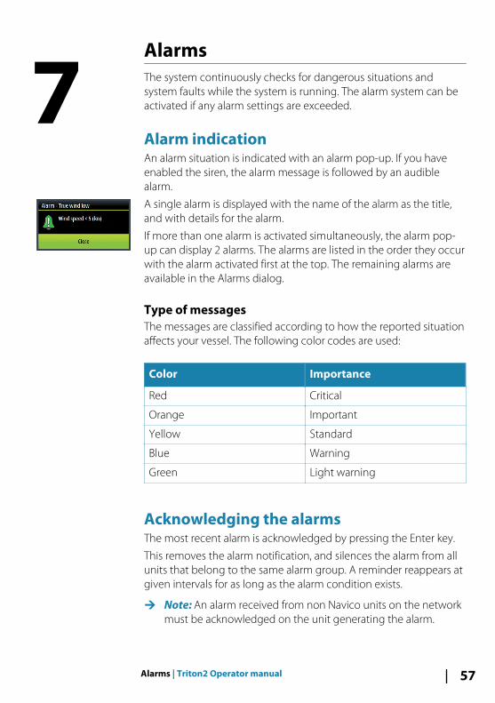
Alarm indicationAn alarm situation is indicated with an alarm pop-up. If you haveenabled the siren, the alarm message is followed by an audiblealarm.
A single alarm is displayed with the name of the alarm as the title,and with details for the alarm.
If more than one alarm is activated simultaneously, the alarm pop-up can display 2 alarms. The alarms are listed in the order they occurwith the alarm activated first at the top. The remaining alarms areavailable in the Alarms dialog.
Type of messagesThe messages are classified according to how the reported situationaffects your vessel. The following color codes are used:
Color Importance
Red Critical
Orange Important
Yellow Standard
Blue Warning
Green Light warning
Acknowledging the alarmsThe most recent alarm is acknowledged by pressing the Enter key.
This removes the alarm notification, and silences the alarm from allunits that belong to the same alarm group. A reminder reappears atgiven intervals for as long as the alarm condition exists.
Ú Note: An alarm received from non Navico units on the networkmust be acknowledged on the unit generating the alarm.
7
Alarms | Triton2 Operator manual 57
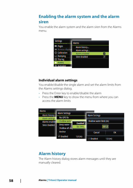
Enabling the alarm system and the alarmsirenYou enable the alarm system and the alarm siren from the Alarmsmenu.
Individual alarm settingsYou enable/disable the single alarm and set the alarm limits fromthe Alarms settings dialog.
• Press the Enter key to enable/disable the alarm• Press the MENU key to show the menu from where you can
access the alarm limits
Alarm historyThe Alarm history dialog stores alarm messages until they aremanually cleared.
58 Alarms | Triton2 Operator manual
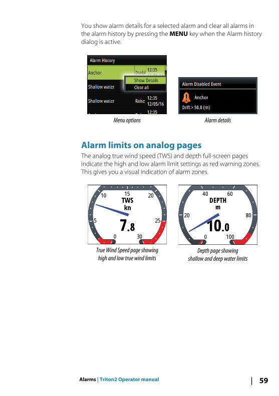
You show alarm details for a selected alarm and clear all alarms inthe alarm history by pressing the MENU key when the Alarm historydialog is active.
Menu options Alarm details
Alarm limits on analog pagesThe analog true wind speed (TWS) and depth full-screen pagesindicate the high and low alarm limit settings as red warning zones.This gives you a visual indication of alarm zones.
True Wind Speed page showinghigh and low true wind limits
Depth page showingshallow and deep water limits
Alarms | Triton2 Operator manual 59

Software setupPrior to use, the Triton2 requires a number of settings be configuredin order for the system to perform as expected. Access to therequired options are found in the Settings menu, accessed from thepage menu or by pressing the MENU key twice.
Ú Note: The following settings are described in other sections ofthis manual:"Race timer" on page 28"Pages" on page 15"Trip log" on page 29"Alarms" on page 57"Autopilot settings" on page 47"AIS settings" on page 36
Remote displaysAny compatible B&G HV display connected to the network can beconfigured to show desired data via the Triton2.
All HV Displays are listed in the Remote displays dialog. Displays notpresent on the network are greyed out.
1. Select the type of display you want to configure- Connected displays of the selected type are listed
2. Highlight the display you want to configure- The HV display itself starts flashing
3. Press the MENU key to display the options available:
8
60 Software setup | Triton2 Operator manual

• Select data: Used for defining which data that should bedisplayed on the selected HV display
• White backlight: Sets the the backlight to white
Ú Note: This option is not available for the 40/40 HV display
• Display group: Sets the network group for the unit
• Instance: Sets the network instance for the unit
For more information about network groups and instance settings,refer to "Network" on page 69.
CalibrationÚ Note: Once the unit is setup and before you proceed with
calibration ensure all network sources are selected andconfigured. Refer to "System settings" on page 69.
Boat speedSpeed calibration is necessary to compensate for hull shape andpaddlewheel location on your boat. For accurate speed and logreadings, it is essential that the paddlewheel is calibrated.
SOG referenceThis is an auto calibration option that uses speed over ground (SOG)from your GPS, and compares the average of SOG against theaverage boat speed from the speed sensor for the duration of thecalibration run.
Ú Note: This calibration should be made in calm sea with noeffect from wind or tidal current.
Software setup | Triton2 Operator manual 61
• Bring the boat up to cruising speed (above 5 knots), then• Select the SOG reference option
When the calibration is completed the Boat speed calibration scalewill show the adjusted percentage value of the boat speed.
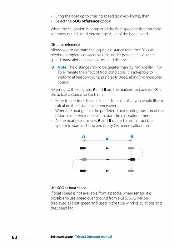
Distance referenceAllows you to calibrate the log via a distance reference. You willneed to complete consecutive runs, under power at a constantspeed made along a given course and distance.
Ú Note: The distance should be greater than 0.5 NM, ideally 1 NM.To eliminate the effect of tidal conditions it is advisable toperform at least two runs, preferably three, along the measuredcourse.
Referring to the diagram, A and B are the markers for each run. X isthe actual distance for each run.
• Enter the desired distance in nautical miles that you would like tocalculate the distance reference over
• When the boat gets to the predetermined starting position of thedistance reference calculation, start the calibration timer
• As the boat passes marks A and B on each run, instruct thesystem to start and stop and finally OK to end calibration.
xBA
Use SOG as boat speedIf boat speed is not available from a paddle wheel sensor, it ispossible to use speed over ground from a GPS. SOG will bedisplayed as boat speed and used in the true wind calculations andthe speed log.
62 Software setup | Triton2 Operator manual
Wind
MHU (Masthead unit) alignmentThis provides an off set calibration in degrees to compensate for anymechanical misalignment between the masthead unit and thecenter line of the vessel.
To check the masthead unit alignment error we recommend youuse the following method which involves a sailing trial:
• Sail on a starboard tack on a close hauled course and record thewind angle, then repeat the process on a port tack
• Divide the difference between the two recorded numbers andenter this as the wind angle off set
If the starboard apparent wind angle is greater than the port angle,then divide the difference by 2 and enter this as a negative offset.
If the port angle is greater than the starboard then divide thedifference by 2 and enter this as a positive offset.
Enter the offset it into the MHU Align calibration field.
True wind angle
Ú Note: This option is only available if an H5000 CPU is connectedto the system.
There are two methods of calibrating TWA:
• monitoring true wind direction from tack to tack• use the compass to verify the angles the yacht is tacking or
gybing through
Start the TWA calibration process for either method by setting theboat up to do a number of tacks upwind or gybes downwind in assteady conditions as possible.
• Method 1 - Monitor True Wind Direction changesIf an error is seen in true wind direction, then the following ruleapplies:
- If true wind direction is being shown as a lift each time youtack then True Wind Angle is reading too wide, half the errormust be subtracted from the TWA correction table
- If true wind direction is being shown as a header each timeyou tack then True Wind Angle is reading too narrow, add halfthe error to the TWA correction table
Software setup | Triton2 Operator manual 63

• Method 2 - Monitor tacking anglesIf according to the compass you are tacking through an angledifferent than the sum of the True Wind Angles on each tack(Port TWA + Starboard TWA) then the following rule applies:
- If the tack angle < the sum of the TWA’s, the True Wind Angleis reading too wide, half the error must be subtracted from theTWA correction table
- If the tack angle > the sum of the TWA’s, the True Wind Angleis reading too narrow, add half the error to the TWA correctiontable
Ú Note: Ensure your compass is correctly calibrated beforecarrying out TWA calibration using either method.
True wind speed
Ú Note: This option is only available if an H5000 CPU is connectedto the system.
True Wind Speed errors are seen from sailing upwind to downwind.This is due to the acceleration of the airflow over the top of the mastand around the sails when sailing downwind. -10% is the defaultvalue for TWA calibration. Monitoring the change in True WindSpeed from close hauled to broad reaching will enable furtherrefinement of this calibration value.
Motion
Ú Note: This option is only available if an H5000 CPU is connectedto the system.A 3D Motion sensor and mast height value is required inconjunction with a CPU running Hercules level software orgreater to use this feature.
When the wind is measured it is initially corrected for masthead unitalignment offset and mast rotation. Set the mast height and tickMotion Correction for motion correction to be applied to measuredwind speed and wind angle.
Depth
Depth offsetAll transducers measure water depth from the transducer to thebottom. As a result, water depth readings do not account for the
64 Software setup | Triton2 Operator manual

distance from the transducer to the lowest point of the boat (forexample; bottom of the keel, rudder, or propeller) in the water orfrom the transducer to the water surface.
• For depth below keel (A): Set the distance from transducer to thebottom of the keel as a negative value. For example, -2.0.
• For depth below transducer (B): no offset required.
• For depth below surface (waterline) (C): Set the distance fromtransducer to the surface as a positive value. For example,+0.5.
A B C
+0.5
+0.0
-2.0
Aft depth offsetThis option allows the system to display two depth readings.
The Aft depth is calibrated in the same manner as the Depth offset.
Ú Note: Aft Depth is only available when a valid signal is receivedfrom a second and compatible NMEA 2000 or NMEA 0183device.
Heading
Ú Note: All magnetic compasses must be calibrated to ensurecorrect heading reference.The calibration must be made on the active compass.The calibration should be done in calm sea conditions and withminimal wind and current to obtain good results.
Software setup | Triton2 Operator manual 65

OffsetThe Offset option is used for compensating for any differencebetween the boat’s center line (A) and the compass lubber line (B).
1. Find the bearing from the boat position to a visible object. Use achart or a chart plotter
2. Steer the boat so that the center line of the boat is aligned withthe bearing line pointing towards the object.
3. Change the offset parameter so that the bearing to the objectand the compass readout becomes equal.
Ú Note: Make sure that both the compass heading and thebearing to the object have the same unit (°M or °T).
User triggered calibration
Ú Note: Before the calibration is started, make sure that there isenough open water around the vessel to make a full turn.
The Calibrate option is used for manually starting the headingcalibration procedure.
During this calibration, the compass measures the magnitude anddirection of the local magnetic field.
The illustration shows magnitude of local field in percentage ofearth's magnetic field (A), direction of local field (B) with respect tothe boat's centerline (C).
Follow the on-screen instruction, and use about 60-90 seconds tomake a full circle. Keep turning until the system reports a pass.
• If the local magnetic field is stronger than the earth’s magneticfield (the local field is reading more than 100%), the compasscalibration will fail.
• If the local field is reading more than 30%, you should look forany interfering magnetic objects and remove them, or youshould move the compass to a different location. The (local) fieldangle guides you to the local interfering magnetic object.
Ú Note: In certain areas and at high latitudes the local magneticinterference becomes more significant, and heading errorsexceeding ±3° may have to be accepted.
B
A
x
20%
030˚
030˚
B
C
A
66 Software setup | Triton2 Operator manual

Automatic calibrationThe Auto calibrate option is used for compasses that offers a fullyautomatic calibration procedure.
See more instructions in the documentation delivered with yourcompass.
Magnetic variationDefines how magnetic variation is handled by the system.
• Auto: Receives variation data from a network source
• Manual: Used for manually entering a value for the magneticvariation
Use COG as headingIf heading data is not available from a compass sensor, it is possibleto use COG from a GPS. COG will be used in the true windcalculations.
Ú Note: The autopilot cannot be operated using COG as theheading source. COG cannot be calculated when stationary.
Heel/TrimIf a suitable sensor is fitted, the system will monitor the inclination ofthe vessel. The offset value should be entered to adjust the readingsso that while the vessel is stationary at the dock, the Heel and Trimvalue reads 0.
EnvironmentIf a suitable sensor is fitted, the system will monitor the currentsea/air temperature and barometric pressure.
The offset value to be entered should adjust the reading from thesensor to match a calibrated source.
RudderStarts the automatic calibration of the rudder feedback. Thisprocedure sets the correct relationship between the physical ruddermovement and the rudder angle readout.
Follow the instructions on the display to perform the rudderfeedback calibration procedure.
Software setup | Triton2 Operator manual 67
Laylines
Ú Note: This option is only available if an H5000 CPU is connectedto the system.
Tidal flow correctionCalculates the tidal flow and offsets the laylines accordingly.
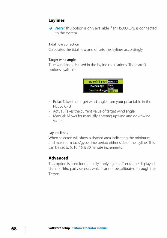
Target wind angleTrue wind angle is used in the layline calculations. There are 3options available:
• Polar: Takes the target wind angle from your polar table in theH5000 CPU
• Actual: Takes the current value of target wind angle• Manual: Allows for manually entering upwind and downwind
values
Layline limitsWhen selected will show a shaded area indicating the minimumand maximum tack/gybe time period either side of the layline. Thiscan be set to 5, 10, 15 & 30 minute increments.
AdvancedThis option is used for manually applying an offset to the displayeddata for third party sensors which cannot be calibrated through theTriton2.
68 Software setup | Triton2 Operator manual
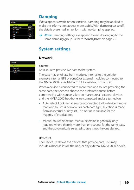
DampingIf data appears erratic or too sensitive, damping may be applied tomake the information appear more stable. With damping set to off,the data is presented in raw form with no damping applied.
Ú Note: Damping settings are applied to units belonging to thesame damping group. Refer to "Network groups" on page 72.
System settings
Network
SourcesData sources provide live data to the system.
The data may originate from modules internal to the unit (forexample internal GPS or sonar), or external modules connected tothe NMEA 2000 or via NMEA 0183 if available on the unit.
When a device is connected to more than one source providing thesame data, the user can choose the preferred source. Beforecommencing with source selection make sure all external devicesand the NMEA 2000 backbone are connected and are turned on.
• Auto select: Looks for all sources connected to the device. If morethan one source is available for each data type, selection is madefrom an internal priority list. This option is suitable for themajority of installations.
• Manual source selection: Manual selection is generally onlyrequired where there is more than one source for the same data,and the automatically selected source is not the one desired.
Device list The Device list shows the devices that provide data. This mayinclude a module inside the unit, or any external NMEA 2000 device.
Software setup | Triton2 Operator manual 69

Selecting a device in this list will bring up additional details andactions:
All devices allow allocation of an instance number in the configureoption. Set unique instance numbers on any identical devices onthe network to allow for the unit to distinguish between them. Thedata option shows all data being output by the device. Somedevices will show additional options specific to the device.
Ú Note: Setting the instance number on a 3rd party product istypically not possible.
DiagnosticsThe NMEA 2000 tab on the diagnostics page can provideinformation useful for identifying an issue with the network.
Ú Note: The following information may not always indicate anissue that can be simply resolved with minor adjustment tonetwork layout or connected devices and their activity on thenetwork. However, Rx and Tx errors are most likely indicatingissues with the physical network, which may be resolved bycorrecting termination, reducing backbone or drop lengths, orreducing the number of network nodes (devices).
70 Software setup | Triton2 Operator manual

Bus stateSimply indicates whether the bus is powered, but not necessarilyconnected to any data sources. However, if bus shows as ‘off’, butpower is present along with an increasing error count, it is possiblethat termination or cable topology is incorrect.
Rx OverflowsThe unit received too many messages for its buffer before theapplication could read them.
Rx OverrunsThe unit contained too many messages for its buffer before thedriver could read them.
Rx/Tx ErrorsThese two numbers increase when there are error messages, anddecrease when messages are received successfully. These (unlikethe other values) are not a cumulative count. Under normaloperation these should be at 0. Values around 96 upwards indicatea heavily error prone network. If these numbers go too high for agiven device, it will automatically drop off the bus.
Rx/Tx MessagesShows actual traffic in and out of device.
Bus LoadA high value here indicates network is near full capacity. Somedevices automatically adjust rate of transmission, if network traffic isheavy.
Fast Packet ErrorsCumulative counter of any fast packet error. This could be a missedframe, or a frame out of sequence etc. NMEA 2000 PGNs are madeof up to 32 frames. The entire message will be discarded when aframe is missed.
Ú Note: Rx and Tx Errors often indicate an issue with the physicalnetwork, which may be resolved by correcting termination,reducing backbone or drop lengths, or reducing the number ofnetwork nodes (devices).
Software setup | Triton2 Operator manual 71
Network groupsThe Network Group function is used to control parameter settings,either globally or in groups of units. The function is used on largervessels where several units are connected to the network. Byassigning several units to the same group, a parameter update onone unit will have the same effect on the rest of the groupmembers.
UnitsProvides setup of units of measure used on various data types.
Decimal placesDefines number of decimals used for speed and sea temperature.
Key beepsControls the loudness of the beep sound when a key is pressed.
Default setting: Loud
LanguageControls the language used on this unit for panels, menus, anddialogs. Changing the language causes the unit to restart.
TimeControls the local time zone offset, and the format of the time anddate.
Display setupDisplays the Display setup dialog.
The following options are available:
• Backlight level: Adjusts the backlight level from Min (10%) to Max(100%) in 10% increments
- When the Backlight level field is active, subsequent presses onthe backlight key adjusts backlight level in decrements of 30%
• Display group: Defines which network group the unit belongs to
• Night mode: Activates/deactivates the night mode color palette
• Night mode color: Sets the night mode color palette
72 Software setup | Triton2 Operator manual

• Invert day color: Changes the background color for the pagesfrom default white to black
• Sleep: Turns the backlight for screen and keys off to save power
Display mode
The Triton2 unit can set up as an instrument only, as an autopilotdisplay only, or as a combination of those two display modes.
• Instrument display only: Displays active data pages. The Autopilotpage can be one of these data pages
• Autopilot display only: Displays only the autopilot page
• Autopilot display when engaged: Switches automatically to theAutopilot page when the autopilot is switched to an automaticmode. When the autopilot is switched to Standby mode thedisplay switches back to the previous page. This behaviour doesnot require that an Autopilot page selected is as one of the 8enabled pages
The Display mode dialog have the following additional options:
• Show MOB: Switches automatically to the MOB page if a ManOver Board event is triggered from another system on thenetwork. Refer to "Man Over Board (MOB)" on page 13
• Show autopilot advanced settings: Displays all available autopilotsettings. Refer to "Sailing (H5000)" on page 50.
FilesFile management system. Used to browse the contents of the unit'sinternal memory and the content of a device plugged into the unit'sUSB port.
Software setup | Triton2 Operator manual 73

SimulateRuns the display with simulated data. Use the simulator to becomefamiliar with your unit before using it on the water.
When activated, the simulator mode is indicated on the display.
Restore defaultsAllows you to select which settings are to be restored to theiroriginal factory settings.
Engine setup
Vessel setupSet the number of engines, fuel tanks and total fuel capacity.
Engine display setupA maximum of two engine’s data can be shown on each gauge.
The Engine display setup defines which engine’s data should bedisplayed on a gauge if you have more than 2 engines.
Gauge limitsSets the RPM and vessel fuel rate limits.
Ú Note: These limits are a visual guide on the data pages. They donot set any alarms.
Global resetResets the source selection on all displays connected to thenetwork.
AboutDisplays copyright information, software version, and technicalinformation for this unit.
74 Software setup | Triton2 Operator manual
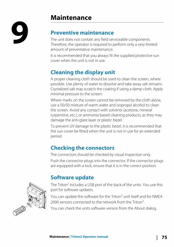
Maintenance
Preventive maintenanceThe unit does not contain any field serviceable components.Therefore, the operator is required to perform only a very limitedamount of preventative maintenance.
It is recommended that you always fit the supplied protective suncover when the unit is not in use.
Cleaning the display unitA proper cleaning cloth should be used to clean the screen, wherepossible. Use plenty of water to dissolve and take away salt remains.Crystalized salt may scratch the coating if using a damp cloth. Applyminimal pressure to the screen.
Where marks on the screen cannot be removed by the cloth alone,use a 50/50 mixture of warm water and isopropyl alcohol to cleanthe screen. Avoid any contact with solvents (acetone, mineralturpentine, etc.), or ammonia based cleaning products, as they maydamage the anti-glare layer or plastic bezel.
To prevent UV damage to the plastic bezel, it is recommended thatthe sun cover be fitted when the unit is not in use for an extendedperiod.
Checking the connectorsThe connectors should be checked by visual inspection only.
Push the connector plugs into the connector. If the connector plugsare equipped with a lock, ensure that it is in the correct position.
Software updateThe Triton2 includes a USB port of the back of the units. You use thisport for software updates.
You can update the software for the Triton2 unit itself and for NMEA2000 sensors connected to the network from the Triton2.
You can check the units software version from the About dialog.
9
Maintenance | Triton2 Operator manual 75
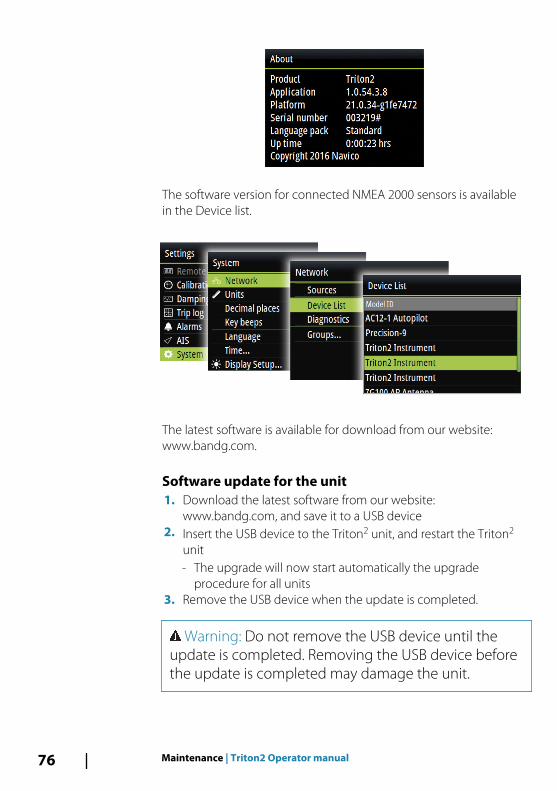
The software version for connected NMEA 2000 sensors is availablein the Device list.
The latest software is available for download from our website:www.bandg.com.
Software update for the unit1. Download the latest software from our website:
www.bandg.com, and save it to a USB device2. Insert the USB device to the Triton2 unit, and restart the Triton2
unit- The upgrade will now start automatically the upgrade
procedure for all units3. Remove the USB device when the update is completed.
Warning: Do not remove the USB device until theupdate is completed. Removing the USB device beforethe update is completed may damage the unit.
76 Maintenance | Triton2 Operator manual

Software update for remote devices1. Download the latest software from our website:
www.bandg.com, and save it to a USB device2. Insert the USB device to the Triton2 unit3. Start the File explorer, and select the update file on the USB
device4. Start the update from the file details dialog5. Remove the USB device when the update is completed.
Maintenance | Triton2 Operator manual 77
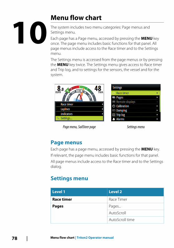
Menu flow chartThe system includes two menu categories: Page menus andSettings menu.
Each page has a Page menu, accessed by pressing the MENU keyonce. The page menu includes basic functions for that panel. Allpage menus include access to the Race timer and to the Settingsmenu.
The Settings menu is accessed from the page menus or by pressingthe MENU key twice. The Settings menu gives access to Race timerand Trip log, and to settings for the sensors, the vessel and for thesystem.
Page menu, SailSteer page Settings menu
Page menusEach page has a page menu, accessed by pressing the MENU key.
If relevant, the page menu includes basic functions for that panel.
All page menus include access to the Race timer and to the Settingsdialog.
Settings menu
Level 1 Level 2
Race timer Race Timer
Pages Pages...
AutoScroll
AutoScroll time
10
78 Menu flow chart | Triton2 Operator manual
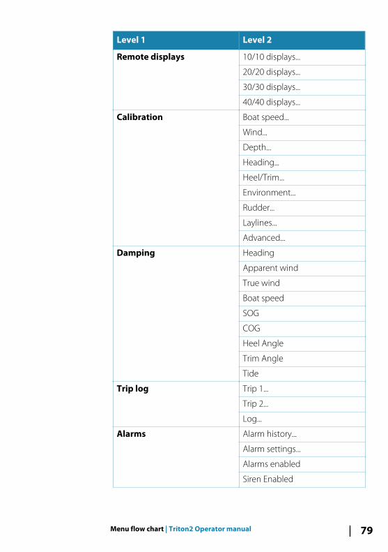
Level 1 Level 2
Remote displays 10/10 displays...
20/20 displays...
30/30 displays...
40/40 displays...
Calibration Boat speed...
Wind...
Depth...
Heading...
Heel/Trim...
Environment...
Rudder...
Laylines...
Advanced...
Damping Heading
Apparent wind
True wind
Boat speed
SOG
COG
Heel Angle
Trim Angle
Tide
Trip log Trip 1...
Trip 2...
Log...
Alarms Alarm history...
Alarm settings...
Alarms enabled
Siren Enabled
Menu flow chart | Triton2 Operator manual 79
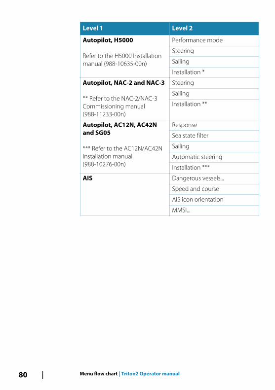
Level 1 Level 2
Autopilot, H5000
Refer to the H5000 Installationmanual (988-10635-00n)
Performance mode
Steering
Sailing
Installation *
Autopilot, NAC-2 and NAC-3
** Refer to the NAC-2/NAC-3Commissioning manual(988-11233-00n)
Steering
Sailing
Installation **
Autopilot, AC12N, AC42Nand SG05
*** Refer to the AC12N/AC42NInstallation manual(988-10276-00n)
Response
Sea state filter
Sailing
Automatic steering
Installation ***
AIS Dangerous vessels...
Speed and course
AIS icon orientation
MMSI...
80 Menu flow chart | Triton2 Operator manual
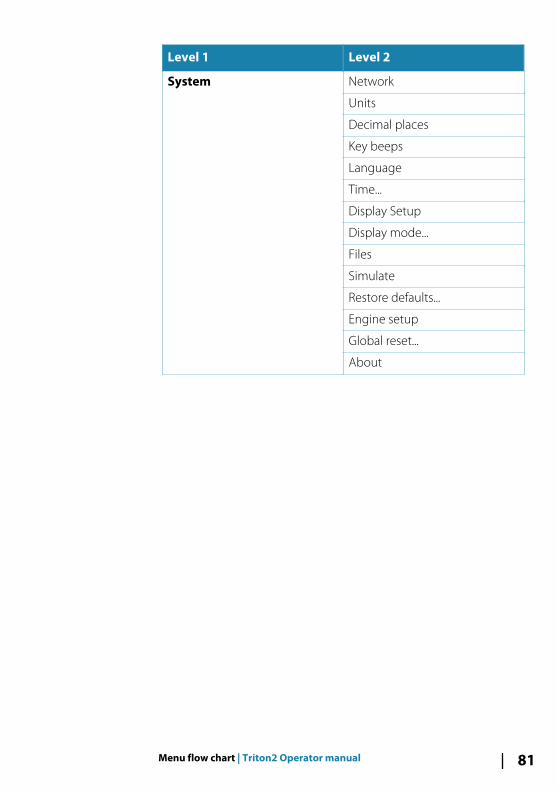
Level 1 Level 2
System Network
Units
Decimal places
Key beeps
Language
Time...
Display Setup
Display mode...
Files
Simulate
Restore defaults...
Engine setup
Global reset...
About
Menu flow chart | Triton2 Operator manual 81

Technical specification
Dimensions Refer to "Dimensional drawing" onpage 83
Weight 0.32 kg (0.7 lbs)
Power consumption 1.8 Watts
Key backlight off 0.54 W
Key backlight max 1.35 W
Network load 3 LEN
Color Black
Display
Size 4.1" (diagonal). 4:3 Aspect ratio
TypeTransmissive TFT-LCD. WhiteLED backlight
Resolution 320 x 240 pixels
IlluminationWhite for day mode. Red, green,blue or white for night mode
Environmental protection
Waterproof rating IPx7
Humidity 100% RH
Temperature
Operating -25° to +65ºC (-13°F to +149 ºF)
Storage -40° to +85ºC (-40°F to +185 ºF)
11
82 Technical specification | Triton2 Operator manual
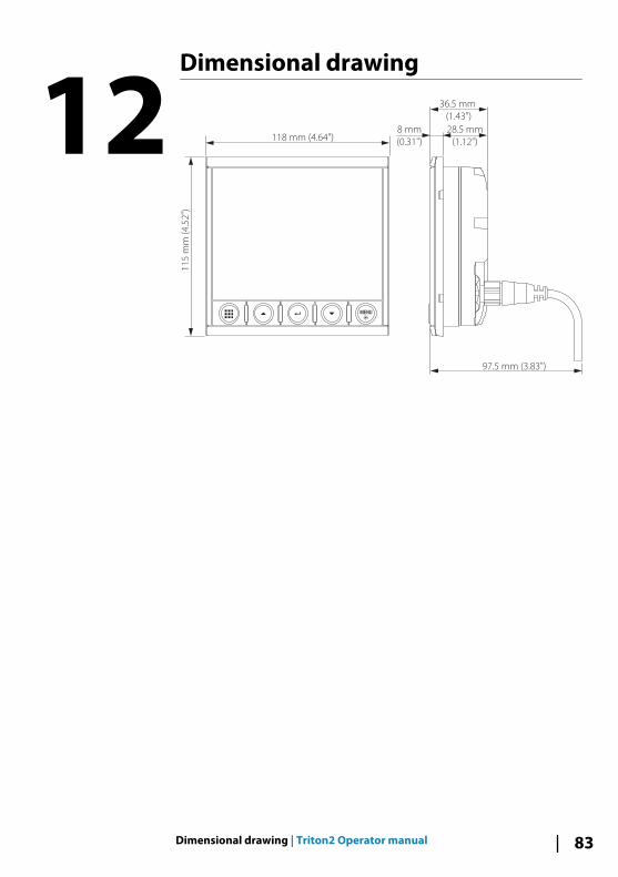
Dimensional drawing
118 mm (4.64")
11
5 m
m (
4.5
2")
8 mm
(0.31")
36.5 mm
(1.43")
28.5 mm
(1.12")
97.5 mm (3.83")
12
Dimensional drawing | Triton2 Operator manual 83
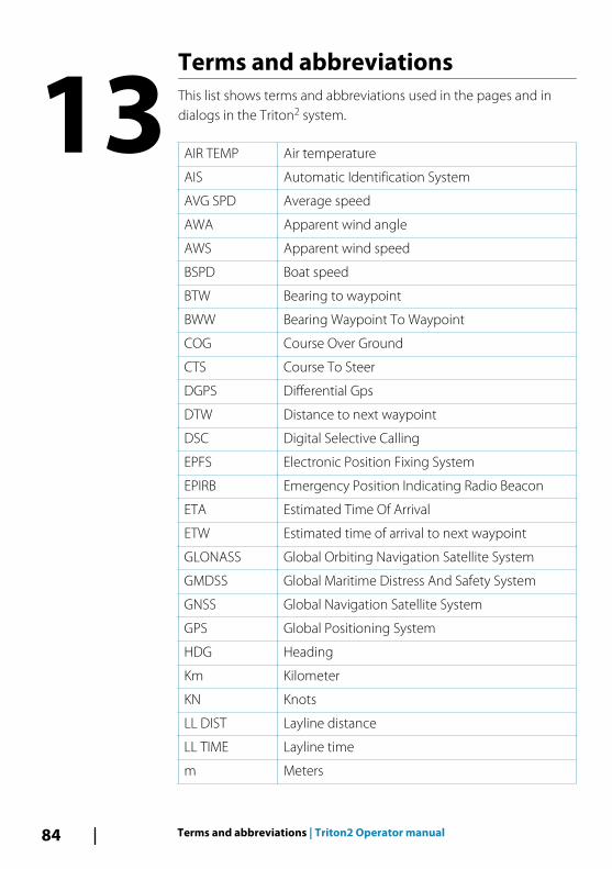
Terms and abbreviationsThis list shows terms and abbreviations used in the pages and indialogs in the Triton2 system.
AIR TEMP Air temperature
AIS Automatic Identification System
AVG SPD Average speed
AWA Apparent wind angle
AWS Apparent wind speed
BSPD Boat speed
BTW Bearing to waypoint
BWW Bearing Waypoint To Waypoint
COG Course Over Ground
CTS Course To Steer
DGPS Differential Gps
DTW Distance to next waypoint
DSC Digital Selective Calling
EPFS Electronic Position Fixing System
EPIRB Emergency Position Indicating Radio Beacon
ETA Estimated Time Of Arrival
ETW Estimated time of arrival to next waypoint
GLONASS Global Orbiting Navigation Satellite System
GMDSS Global Maritime Distress And Safety System
GNSS Global Navigation Satellite System
GPS Global Positioning System
HDG Heading
Km Kilometer
KN Knots
LL DIST Layline distance
LL TIME Layline time
m Meters
13
84 Terms and abbreviations | Triton2 Operator manual
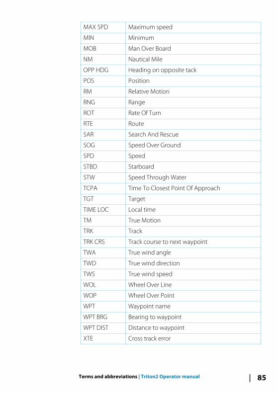
MAX SPD Maximum speed
MIN Minimum
MOB Man Over Board
NM Nautical Mile
OPP HDG Heading on opposite tack
POS Position
RM Relative Motion
RNG Range
ROT Rate Of Turn
RTE Route
SAR Search And Rescue
SOG Speed Over Ground
SPD Speed
STBD Starboard
STW Speed Through Water
TCPA Time To Closest Point Of Approach
TGT Target
TIME LOC Local time
TM True Motion
TRK Track
TRK CRS Track course to next waypoint
TWA True wind angle
TWD True wind direction
TWS True wind speed
WOL Wheel Over Line
WOP Wheel Over Point
WPT Waypoint name
WPT BRG Bearing to waypoint
WPT DIST Distance to waypoint
XTE Cross track error
Terms and abbreviations | Triton2 Operator manual 85
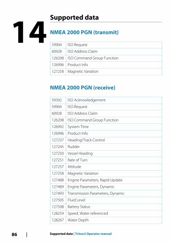
Supported data
NMEA 2000 PGN (transmit)
59904 ISO Request
60928 ISO Address Claim
126208 ISO Command Group Function
126996 Product Info
127258 Magnetic Variation
NMEA 2000 PGN (receive)
59392 ISO Acknowledgement
59904 ISO Request
60928 ISO Address Claim
126208 ISO Command Group Function
126992 System Time
126996 Product Info
127237 Heading/Track Control
127245 Rudder
127250 Vessel Heading
127251 Rate of Turn
127257 Attitude
127258 Magnetic Variation
127488 Engine Parameters, Rapid Update
127489 Engine Parameters, Dynamic
127493 Transmission Parameters, Dynamic
127505 Fluid Level
127508 Battery Status
128259 Speed, Water referenced
128267 Water Depth
14
86 Supported data | Triton2 Operator manual

128275 Distance Log
129025 Position, Rapid Update
129026 COG & SOG, Rapid Update
129029 GNSS Position Data
129033 Time & Date
129038 AIS Class A Position Report
129039 AIS Class B Position Report
129040 AIS Class B Extended Position Report
129041 AIS aids to Navigation
129283 Cross Track Error
129284 Navigation Data
129283 Cross Track Error
129284 Navigation Data
129539 GNSS DOPs
129540 GNSS Sats in View
129794 AIS Class A Static and Voyage Related Data
129801 AIS Addressed Safety Related Message
129802 AIS Safety Related Broadcast Message
129808 DSC Call Information
129809 AIS Class B “CS” Static Data Report, Part A
129810 AIS Class B “CS” Static Data Report, Part B
130074 Route and WP Service - WP List - WP Name & Position
130306 Wind Data
130310 Environmental Parameters
130311 Environmental Parameters
130312 Temperature
130313 Humidity
130314 Actual Pressure
130576 Small Craft Status
130577 Direction Data
Supported data | Triton2 Operator manual 87

*988
-112
14-0
01*