sdn-based 5g mobile networks: architecture, functions, … · sdn-based 5g mobile networks:...
TRANSCRIPT

TRANSACTIONS ON EMERGING TELECOMMUNICATIONS TECHNOLOGIESTrans. Emerging Tel. Tech. (2014)
Published online in Wiley Online Library (wileyonlinelibrary.com). DOI: 10.1002/ett.2915
INVITED PAPER
SDN-based 5G mobile networks: architecture,functions, procedures and backward compatibilityR. Trivisonno*, R. Guerzoni, I. Vaishnavi and D. SoldaniHuawei European Research Institute, Munich, Germany
ABSTRACT
In this paper, we describe an SDN-based plastic architecture for 5G networks, designed to fulfill functional and per-formance requirements of new generation services and devices. The 5G logical architecture is presented in detail, andkey procedures for dynamic control plane instantiation, device attachment, and service request and mobility managementare specified. Key feature of the proposed architecture is flexibility, needed to support efficiently a heterogeneous set ofservices, including Machine Type Communication, Vehicle to X and Internet of Things traffic. These applications areimposing challenging targets, in terms of end-to-end latency, dependability, reliability and scalability. Additionally, back-ward compatibility with legacy systems is guaranteed by the proposed solution, and Control Plane and Data Plane are fullydecoupled. The three levels of unified signaling unify Access, Non-access and Management strata, and a clean-slate for-warding layer, designed according to the software defined networking principle, replaces tunneling protocols for carriergrade mobility. Copyright © 2014 John Wiley & Sons, Ltd.
*Correspondence
R. Trivisonno, Huawei European Research Institute, Munich, Germany.E-mail: [email protected]
Received 13 October 2014; Revised 5 November 2014; Accepted 8 November 2014
1. INTRODUCTION
The evolution of mobile broadband networks is cur-rently driven by the definition of next generation servicesand related requirements. Within mainstream researchframeworks, key challenges for 5G are being identified[1–3]. Beyond system capacity and scalability require-ments (thousand-fold capacity increase with respect to 4Gand ability to provide connectivity to billions of devices),tight constraints in terms of latency and reliability will bealso imposed by delay critical services, such as virtual real-ity office, teleprotection for smart grids, real-time remotecomputing for mobile terminals, and traffic safety andefficiency, which are regarded as key use cases for 5G net-works [1]. Moreover, next generation systems are expectedto enable brand new classes of services, required by emerg-ing vertical markets, including Machine Type Communi-cation (MTC), vehicle to X (V2X) communications andInternet of Things (IoT) traffic.
The most stringent requirements trigger ad hoc researchactivities, aiming at boosting performance of specificenabling technologies of future networks. For exam-ple, 5G capacity requirements call for spectral efficiencyimprovements, which stimulate research on interference
management (e.g. see [4, 5] and [6] for device to devicecommunications). Besides specific performance require-ments, the heterogeneity of services, devices and accessnetworks 5G shall support, will undoubtedly impose radi-cal changes to network architecture. It is worth noting that3rd Generation Partnership Project and ETSI have alreadyaddressed the issue, planning functional adjustments to4G, to optimise the management of diverse use cases anddevices (see [7] and [8], where ad hoc solutions for MTCcommunications and multicast-broadcast multimedia ser-vices are analysed). In order to manage such heterogeneity,flexibility is going to be the key feature of next genera-tion networks. The required architectural flexibility can beachieved by design, leveraging Software Defined Network-ing (SDN), Network Functions Virtualisation, and cloudand edge computing paradigms.
Several prominent proposals of SDN-based architec-tures were recently published. In [9], authors describeda generic Software Defined Wireless Network architec-ture, based on a common core network (CN) and a vari-ety of radio access networks (RANs), orchestrated by aMobile Network SDN Controller. In the proposed archi-tecture, RANs are enhanced with programmability, and thetransport network consists of programmable switches and
Copyright © 2014 John Wiley & Sons, Ltd.

R. Trivisonno et al.
routers. Both ‘evolutionary’ and ‘clean-slate’ approacheswere proposed. The first approach allows incrementaldeployment in existing networks. In this case, the SDNcontroller implements the required standardised interfaces.In the latter clean-slate approach, Control Plane (C-Plane)functions are directly programmed into the SDN controller.Similarly, in [10], authors discussed a 5G mobile archi-tecture made by two network layers: a radio network,providing a minimum set of L2 and L1 functionalities,and a network cloud dedicated to all higher layer func-tionalities. The proposal claims a lean protocol stack thatcan be achieved by consolidating redundant Access Stra-tum (AS) and Non-access Stratum (NAS) functionalities.Such integration allows a simplification of mobility man-agement, session management and security procedures. Onthe user plane, dynamic network deployment and abilityto scale are achieved by merging RAN L2 and gatewayfunctionalities in the CN. Another notable proposal canbe found in [11]. The paper describes an all-SDN net-work architecture featuring hierarchical control capability.More specifically, the article focuses on a 5G C-Planeaiming at providing Connectivity Management (CM) asa Service, with a ‘unified’ approach to mobility, handoffand routing management. According to the authors, ‘Uni-fied’ relates to merging RAN and CN functions, which areimplemented as network applications running on one ormore hierarchical controllers.
Harvesting some high-level concepts presented in priorart, this paper develops an SDN-based plastic architec-ture for 5G networks. The term plastic relates to thekey characteristic of our proposal: both C-Plane and DataPlane (D-Plane) are not prescribed; rather, the C-Planeand D-Plane are tailored according to the requirementsof specific applications and devices. Any network func-tion, and corresponding states, is dynamically instantiatedand interconnected within the cloud infrastructure, accord-ing to application and device performance and relevantfunctional requirements. This approach aims at achievingefficiently the target 5G key performance indicators byoptimising the physical infrastructure utilisation and allow-ing backward compatibilities with legacy communicationsystems. Indeed, compatibility with 4G systems is regardedby the authors as a strict prerequisite for the adoptionand market uptake of the proposed concepts for the nextgeneration networks.
Section 2 reviews briefly the key 5G performance met-rics and highlights the design rationale we followed to con-ceive the proposed plastic architecture, which is describedin Section 3. Section 4 presents in detail how the new pro-cedures for C-Plane instantiation, device attachment, ser-vice request and mobility would efficiently work. Section 5includes a proof of backward compatibility, as it showshow a 4G network could be instantiated using our plas-tic architecture as a platform. Finally, Section 6 concludesthe paper.
2. 5G MOBILE NETWORK DESIGN
2.1. 5G requirements
This paper focuses on 5G system requirements affect-ing the architecture definition according to the researchchallenges presented in [12]. The key requirement for5G architecture is flexibility, as networks must support aheterogeneous set of use cases efficiently. Among those,V2X communications and IoT traffic will place challeng-ing functional and performance requirements on networkplatforms and devices. In particular, V2V communicationrequires a significant latency reduction with respect to 4G,leading to a challenging 5 ms end-to-end delay. Addition-ally, reliable V2V services shall be provided in a variety ofcases, including the out-of-coverage scenario, where oneor both devices in communication cannot get network con-nectivity. IoT traffic requires an extended device ID space(enhanced addressing schemes), well beyond IPv6. More-over, flexibility is also about backward compatibility: 5Garchitecture shall be able to support and coexist with legacy(e.g. 4G) systems.
2.2. 5G design rationale
To meet the requirements briefly reviewed in the previ-ous section, we propose new fundamental design princi-ples. First, 5G architecture shall feature dynamic definitionand instantiation of both C-Plane and D-Plane, accord-ing to service and device types. The customised C-Planeand D-Plane shall enable ad hoc networking procedures(e.g. device attachment and service request) designed toachieve the target 5G key performance indicators. Second,the architecture shall support full (i.e. extended up to theaccess point) C-Plane and D-Plane decoupling, leveragingSDN technologies for transport network implementationand to allow radio dual connectivity. Finally, D-Planeshall be simplified by removing the tunneling concept andintroducing soft packet data network (PDN) and mobilityanchoring points.
3. 5G ARCHITECTURE
3.1. General principles
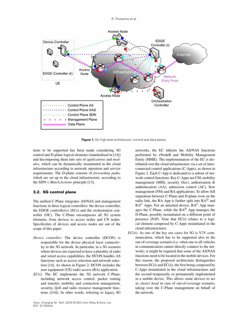
The proposed architecture stems from concepts presentedin [13]. The architecture consists of a unified C-Plane,made by three logical controllers, and a clean-slate D-Plane, both represented in Figure 1.
The 5G unified C-Plane includes both AS/NAS signal-ing and management functions. The implementation ofnetwork functions can be either ‘centralised’ or ‘distributedat the edge’, depending on functional and performancerequirements of the supported services. Additionally, theC-plane includes an SDN plane through which D-Plane isinstantiated and operated. The selection of logical func-
Trans. Emerging Tel. Tech. (2014) © 2014 John Wiley & Sons, Ltd.DOI: 10.1002/ett
R. Trivisonno et al.
Figure 1. 5G High-level architecture—control and data planes.
tions to be supported has been made considering 4Gcontrol and D-plane logical elements (standardised in [14])and decomposing them into sets of applications and mod-ules, which can be dynamically instantiated in the cloudinfrastructure according to network operation and servicerequirements. The D-plane consists of forwarding paths,which are set up in the cloud infrastructure, according tothe SDN < Match,Action> principle [13].
3.2. 5G control plane
The unified C-Plane integrates AS/NAS and managementfunctions in three logical controllers: the device controller,the EDGE controller(s) (ECs) and the orchestration con-troller (OC). The C-Plane encompasses all 5G systemelements, from devices to access nodes and CN nodes.Specificities of devices and access nodes are out of thescope of this paper.
Device controller: The device controller (DCON) isresponsible for the device physical layer connectiv-ity to the 5G network. In particular, in a 5G scenariowhere devices are expected to have a plurality of radioand wired access capabilities, the DCON handles ASfunctions such as access selection and network selec-tion [14]. As shown in Figure 2, DCON includes theuser equipment (UE) radio access (RA) application.
EC(i): The EC implements the 5G network C-Plane,including network access control, packet routingand transfer, mobility and connection management,security, QoS and radio resource management func-tions ([14]). In other words, referring to legacy 4G
networks, the EC inherits the AS/NAS functionsperformed by eNodeB and Mobility ManagementEntity (MME). The implementation of the EC is dis-tributed over the cloud infrastructure via a set of inter-connected control applications (C-Apps), as shown inFigure 2. Each C-App is dedicated to a subset of net-work control functions. Key C-Apps are CM, mobilitymanagement (MM), security (Sec), authorisation &authentication (AA), admission control (AC), flowmanagement (FM) and RA applications. To allow fullseparation between C-Plane and D-plane even on theradio link, the RA App is further split into RAD andRAC Apps. For an attached device, RAC App man-ages the C-Plane, while the RAD App manages theD-Plane, possibly instantiated on a different point ofpresence (PoP). Note that EC(i) relates to a logi-cal element composed by C-Apps instantiated in thecloud infrastructures.
EC(ii): As one of the key use cases for 5G is V2V com-munication, which has to be supported also in theout-of-coverage scenario (i.e. when one or all vehiclesin communication cannot directly connect to the net-work), it might be required that some of the AS/NASfunctions need to be located in the mobile devices. Forthis reason, the proposed architecture distinguishesbetween EC(i) and EC(ii), the first being composed byC-Apps instantiated in the cloud infrastructures andthe second temporarily or permanently implementedin a mobile device. This allows some devices to actas cluster head in case of out-of-coverage scenario,taking over the C-Plane management on behalf ofthe network.
Trans. Emerging Tel. Tech. (2014) © 2014 John Wiley & Sons, Ltd.DOI: 10.1002/ett

R. Trivisonno et al.
Figure 2. 5G control plane.
OC: The OC coordinates the utilisation of cloud resources.It inherits some of the 4G network management func-tions [14], as it is responsible for the allocation andmaintenance of resources required to instantiate both5G control and data planes. As shown in Figure 2,the OC is composed by the resource orchestration(RO) module and the topology management (TM)modules. The RO module decides how to allocatethe available resources to instantiate and intercon-nect EC C-Apps. In other words, the RO determinesthe embedding solution for the virtual control anddata planes to be instantiated within the cloud infras-tructures. The TM module enforces RO decision:it handles the physical resources directly, and it iscomposed by the topology management apps (TM-A) and topology management links (TM-L), whichhandle virtual machines and virtual links, respec-tively, required to instantiate and interconnect theEC C-Apps. The RO is centralised and has visibil-ity over the whole cloud infrastructure, while TM-Aand TM-L are distributed modules interacting withSDN platforms (e.g. Floodlight), to instantiate dataforwarding paths, and with cloud management plat-forms to instantiate the C-Apps. The instantiation ofthe C-Plane consists of embedding the EC(i) Appswhile fulfilling network engineering and applica-tion requirements. Network engineering requirementsinclude the required number, capacity and location ofaccess nodes to provide coverage in the geographi-cal area where 5G services are made available and therequired backhauling capacity between access net-work and CN, according to the expected 5G traffic.The OC is the element guaranteeing network effi-ciency and flexibility: taking into account engineeringrequirements, tailored C-Planes can be instantiatedaccording to application and device requirements.
For example, for basic applications involving staticdevices and not requiring secure communication, abasic C-Plane will be instantiated, for example, notincluding MM, authorisation & authentication andSec Apps. The intelligence placed in the OC is one ofthe key 5G features, which will guarantee efficiencyin resource usage and fulfillment of 5G performancerequirements, in terms of latency, reliability and scal-ability, as addressed in Section 2.
3.3. 5G data plane
A clean-slate design approach for the D-Plane has beenfollowed, based on SDN technology. Neither dedicatedD-Plane network elements (such as 4G SGW and PGWfor instance) nor unique logical elements for the wholeattached device population (such as gateways or mobilityanchor points) are defined. Also, the tunneling concept andprotocols are no longer required.
Simply, during network attachment, an address is allo-cated to the device. Additionally, a last hop routing element(LHRE) and a network entry point (NEP) is associated toit. Then, a forwarding path is established, to allow pack-ets generated by (or directed to) the device to be routedfrom the LHRE to the NEP (or from NEP to LHRE). Theestablishment of a forwarding path requires the FM Appto select the most suitable virtual link between LHRE andNEP, and the physical infrastructure controller to set for-warding tables on switches belonging to the SDN-basedcloud infrastructure. The wireless connection between theRA point and the device is managed by the RA App ofthe EC(i). At service request, the required QoS is enforcedover both the wireless connection and the forwarding path.
LHRE: The LHRE chains the RA point of the device to thebackhaul infrastructure. It represents a soft mobility
Trans. Emerging Tel. Tech. (2014) © 2014 John Wiley & Sons, Ltd.DOI: 10.1002/ett

R. Trivisonno et al.
Figure 3. 5G access architecture—control and data planes.
anchoring point. When a device attaches to the net-
work, a forwarding path from the selected LHRE to
the selected NEP is established by the FM App. The
forwarding path allows packets generated by (directed
to) the device to be forwarded to (from) a NEP (to the
device LHRE).
NEP: The NEP identifies the bound for physical infrastruc-
ture controlled by the OC. It represents a soft PDN
anchoring point. Different attached devices may have
different NEPs, depending on the attachment type
and the related service, which might be requested.
In some cases, the NEP might not be allocated, for
example, in some V2V applications where the traf-
fic is confined within the infrastructure owned by the
service provider.
3.4. 5G access control and data plane
The separation between C-Plane and D-Plane is extended
to the wireless access network. According to the dual con-
nectivity principle, a device might be connected to two
different access points simultaneously, one providing the
(access) C-Plane and the other providing the (access) D-
Plane. Several access network configurations might coexist
in 5G systems, as shown in Figure 3. Each remote radio
unit to which a device can connect is connected to a
PoP, for example, a small edge data center. A PoP can
implement only the RAD App or both the RAD and RAC
Apps. Finally, two PoPs might or might not share the
same LHRE.
4. 5G PROCEDURES
4.1. Control plane instantiation
One of the key innovations introduced by 5G architecturesis the adaptability and flexibility of the C-Plane, whichcan be dynamically reconfigured according to changingconditions related to network engineering requirementsand service performance requirements. In our architecture,the RO module manages the allocation of resources tothe EC(i) Apps. The RO has abstract knowledge of theunderlying infrastructure, mediated by TM modules thathandle the virtualised substrate. In multi-domain or multi-technology environment, the RO may request resourcesfrom TM modules belonging to other networks via cloud-to-cloud application programming interfaces. Each TMmodule handles the resource provisioning and monitoringwithin a single domain and single technology. As shownin Figure 4, the TM-A modules handles the cloud comput-ing resources provisioned by cloud management platforms(e.g. OpenStack, just to mention an open source cloudmanagement platform) and the TM-L module controls thevirtual links maintained by SDN-based control platforms(e.g. Floodlight). The TM modules report resource stateand availability to the RO module, which runs algorithmsfor embedding virtual infrastructures into cloud resources(some examples were presented in [15]).
The instantiation of the C-Plane consists of thefollowing:
� Embedding the EC(i) Apps while fulfilling networkengineering requirements (e.g. network planning,energy consumption or operational cost constraints
Trans. Emerging Tel. Tech. (2014) © 2014 John Wiley & Sons, Ltd.DOI: 10.1002/ett

R. Trivisonno et al.
Figure 4. Control plane instantiation.
Figure 5. Initial device attachment.
and geographical distribution of the devices) and
service performance requirements;
� Configuring virtual links to interconnect EC(i) control
applications.
The procedure for the initial instantiation of the C-
Plane is depicted in Figure 4. The TM modules update
periodically the RO Module about availability and state
of the substrate resources. In step 1, a network engineer-
ing requirement message triggers the embedding algo-
rithm (step 2) in the RO module. The implementation of
the NE requirements may result in instantiating (or de-
instantiating) apps in the cloud infrastructure controlled by
the TM-A module (steps 3.a–5.a) and new C-Plane links
in the SDN-based infrastructure controlled by the SDN
Platform (steps 3.b–5.b).
4.2. Initial device attachment
The 5G initial attach procedure is illustrated in Figure 5.This procedure is managed by the EC(i), assuming that anEC(ii) is not involved.
In step 1, the CM Client in the UE sends an attachrequest to the CM App in the EC(i). The CM client includesin the request the UE identity information as well as thereason of the attachment; for instance, to get assigned anIP address. The request triggers step 2 involving UE iden-tity check, update of the UE location, authentication and,if requested, the allocation of an IP address. Note thatthe usage of IP is only one out of several alternatives forthe addressing mechanism that could be employed in 5Gsystems. The implementation of these procedures may sig-nificantly affect the time elapsed to complete this phase.At the completion of step 2, the CM App requests the FMApp to define and implement the default rules to handle
Trans. Emerging Tel. Tech. (2014) © 2014 John Wiley & Sons, Ltd.DOI: 10.1002/ett

R. Trivisonno et al.
Figure 6. Device triggered service request.
traffic directed to or generated by the UE. This flow con-figuration request is handled by AC App and FM App instep 4. Depending on the type of attachment, the FM Appdetermines the high-level rules for network configuration.For instance,
� Packets directed to the UE shall be routed to theLHRE connected to the access point that serves theUE;
� UE generated packets directed to an external device(not managed by FM App) shall be routed to FM AppNEPs;
� UE generated packets directed to an internal deviceshall be routed to destination.
The rules are checked by the AC App, which determineshow to realise the requested path based on the knowledgeof the physical infrastructure topology and utilisation.
In step 5, the FM App deploys the rules in the SDN-based platform using the appropriate policy defined for theattachment type. For peculiar attachment types related tolow latency services, a proactive deployment of the for-warding rules shall guarantee the required performance.If latency requirements are relaxed or undefined, the for-warding rules can be reactively dispatched by the SDNcontroller whenever an SDN switch needs to resolve theforwarding of the first packet of a data flow belonging tothe UE.
The CM App, after receiving the acknowledgment tothe flow configuration request (step 6), triggers the radioaccess bearer (RAB) setup procedure (step 7). The UECM client completes the procedure by sending the attachcomplete message.
4.3. Device triggered service request
Figure 6 describes the procedure for a device triggeredservice request.
Triggered by an application client, the CM client inthe UE sends a service request to the CM App includingthe identity information of the UE and, optionally, of the
application. The CM App initiates the RAB establish-ment (step 3) and the flow configuration in the SDN-basedinfrastructure (steps 4–7). The RAB may involve differentRA Apps from the one that received the service request;for instance, C-Plane and D-Plane could be managed bydifferent RA Apps. The steps 3, 5 and 6 are similar tothose introduced for the initial attach procedure, with thesole difference that radio bearer and forwarding paths arerelated to a dedicated bearer, which QoS requirements maydepend on the device capabilities, on the specific serviceinstance or on the application requesting the service. Whenthe establishment of radio bearer and forwarding paths iscompleted, the CM app acknowledges the service requestto the UE (step 8). Finally, in step 9, the application clientcan start sending data to the App server.
4.4. Mobility management
The proposed architecture simplifies the current MM pro-cedures. The device is initially camped on a serving (S)cell controlled by the S-RAC App with data connectionto S-RAD App. The simplest mobility case occurs when ahandover is required for the D-plane only, without the needof mobility anchor relocation, that is, when the PoP wherethe target (T) RA D App is instantiated is connected to thesame LHRE as the PoP where the S-RAD App is located.The procedure, shown in Figure 7, starts with the HOpreparation phase (step 1): upon radio link quality mea-surements, the S-RACApp triggers a ‘RAD App only HO’.The T-RADApp is selected by the S-RAC App, then the S-RAC App requires the HO to the T-RAD App. T-RAD Appreserves required resources for the HO and acknowledgesthe HO request to the S-RAC App. The HO executionphase follows (step 2): the S-RAC App executes the HOover the radio interface and notifies the HO completion tothe T-RAD App. Uplink data are now sent from the deviceto the T-RAD App and from T-RADApp to LHRE. Down-link data are sent from LHRE to S-RAD App, forwardedfrom S-RADApp to T-RAD App and then transmitted overradio interface. Finally, forwarding path switch takes placeon the last hop, as indicated in step 3. In this phase the
Trans. Emerging Tel. Tech. (2014) © 2014 John Wiley & Sons, Ltd.DOI: 10.1002/ett

R. Trivisonno et al.
Figure 7. Handover without anchor relocation.
Figure 8. Handover with anchor relocation.
S-RAC App notifies the HO to the CM App, which veri-fies the need for a forwarding path switch. Then, the CMApp requires a forwarding path switch to the FM App,needed for the LHRE to forward data to the PoP wherethe T-RAD App is instantiated. The FM App finds a newpath for data to be forwarded from LHRE to T-RAD App,and finally, the SDN platform enforces the new forwardingpath, configuring forwarding tables in LHRE.
The handover procedure in case of mobility anchor relo-cation (i.e. LHRE change) is depicted in Figure 8. Thedevice is initially camped on a serving (S) cell controlledby the S-RAC App with data connection to S-RAD App.The handover preparation phase (step 1) is initiated by S-RAC App when radio link quality measurements indicatea better service cell exists. During the preparation phase,the target (T) cell and corresponding T-RAD App and T-RAC App are identified. The required resources are thenreserved in the target cell. Then, the execution phase takesplace (step 2). The S-RAC commands the UE to camp on
the cell controlled by the T-RAC App. Radio connectionis established to T-RAC App for C-Plane and to T-RAD
App for D-Plane. The MM App updates information onUE location, the CM App selects the LHRE associated toT-RAC and T-RAD Apps (T-LHRE) and the FM App con-figures temporary uplink data forwarding from T-LHREto S-LHRE. The handover procedure is completed withthe forwarding path switching phase (step 3), where theCM and FM App trigger the reconfiguration of SDN-basedcloud infrastructure to allow packets generated by the UEand forwarded to the T-LHRE to reach their destination, aswell as to allow packets directed to the UE to be properlyforwarded to the T-LHRE. The SDN-based cloud infras-tructure is configured by the SDN platform controller upontrigger by FM App. Finally, it should be noted that incase IP is the addressing mechanism used, ‘Mobile IP’ isnot required, as the IP address and the NEP associated toa device will not change when the access node changesbecause of device mobility.
Trans. Emerging Tel. Tech. (2014) © 2014 John Wiley & Sons, Ltd.DOI: 10.1002/ett
R. Trivisonno et al.
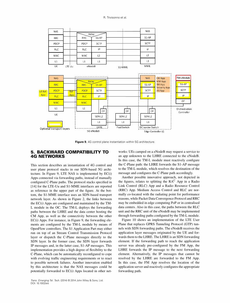
Figure 9. 4G control plane instantiation within 5G architecture.
5. BACKWARD COMPATIBILITY TO4G NETWORKS
This section describes an instantiation of 4G control anduser plane protocol stacks in our SDN-based 5G archi-tecture. In Figure 9, LTE NAS is implemented by EC(i)Apps connected via forwarding paths, instead of manuallyconfigured C-Plane paths. The protocol stacks specified in[14] for the LTE-Uu and S1-MME interfaces are reportedas reference in the upper part of the figure. At the bot-tom, the S1-MME interface uses an SDN-based transportnetwork layer. As shown in Figure 2, the links betweenthe EC(i) Apps are configured and maintained by the TM-L module in the OC. The TM-L deploys the forwardingpaths between the LHRE and the data center hosting theCM App, as well as the connectivity between the otherEC(i) Apps. For instance, in Figure 9, the forwarding ele-ments are configured by the TM-L module by means ofOpenFlow controllers. The S1 Application Part may eitherrun on top of an Stream Control Transmission Protocollayer or dispatch the C-Plane messages directly to theSDN layer. In the former case, the SDN layer forwardsIP messages and, in the latter case, S1-AP messages. Thisimplementation provides a high degree of flexibility to theC-Plane, which can be automatically reconfigured to copewith evolving traffic engineering requirements or to reactto possible network failures. Another innovation enabledby this architecture is that the NAS messages could bepotentially forwarded to EC(i) Apps located in other net-
works: UEs camped on a eNodeB may request a service toan app unknown to the LHRE connected to the eNodeB.In this case, the TM-L module must reactively configurethe C-Plane path: the LHRE forwards the S1-AP messageto the TM-L module, which resolves the destination of themessage and configures the C-Plane path accordingly.
Another possible innovative approach, not depicted inthe figures, relates to splitting the RAC App in a RadioLink Control (RLC) App and a Radio Resource Control(RRC) App. Medium Access Control and RLC are nor-mally co-located with the radiating point for performancereasons, while Packet Data Convergence Protocol and RRCmay be embedded in edge computing PoP or in centraliseddata centers. Also in this case, the paths between the RLCunit and the RRC unit of the eNodeB may be implementedthrough forwarding paths configured by the TM-L module.
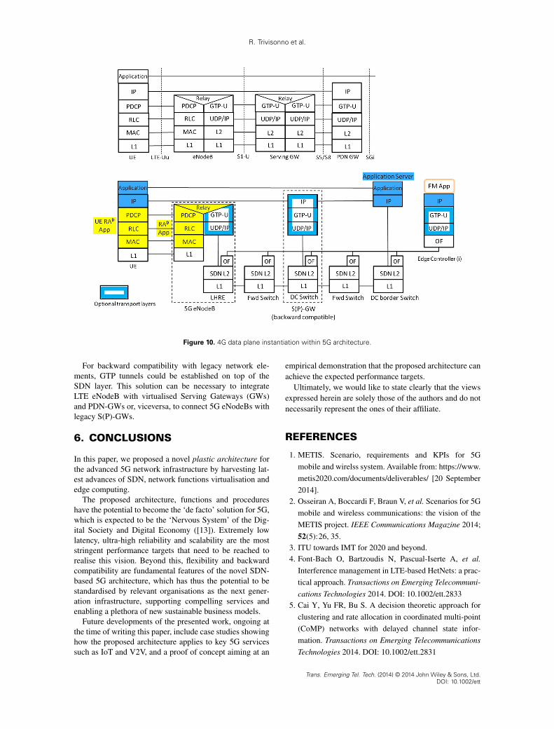
Figure 10 shows an implementation of the LTE UserPlane that replaces GPRS Tunneling Protocol (GTP) tun-nels with SDN forwarding paths. The eNodeB receives theapplication layer messages originated by the UE and for-wards them to the LHRE. The LHRE is an SDN forwardingelement. If the forwarding path to reach the applicationserver was already pre-configured by the FM App, theLHRE forwards the IP message to the next forwardingelement. Alternatively, the IP messages that cannot beresolved by the LHRE are forwarded to the FM App.In this case, the FM App resolves the location of theapplication server and reactively configures the appropriateforwarding path.
Trans. Emerging Tel. Tech. (2014) © 2014 John Wiley & Sons, Ltd.DOI: 10.1002/ett
R. Trivisonno et al.
Figure 10. 4G data plane instantiation within 5G architecture.
For backward compatibility with legacy network ele-ments, GTP tunnels could be established on top of theSDN layer. This solution can be necessary to integrateLTE eNodeB with virtualised Serving Gateways (GWs)and PDN-GWs or, viceversa, to connect 5G eNodeBs withlegacy S(P)-GWs.
6. CONCLUSIONS
In this paper, we proposed a novel plastic architecture forthe advanced 5G network infrastructure by harvesting lat-est advances of SDN, network functions virtualisation andedge computing.
The proposed architecture, functions and procedureshave the potential to become the ‘de facto’ solution for 5G,which is expected to be the ‘Nervous System’ of the Dig-ital Society and Digital Economy ([13]). Extremely lowlatency, ultra-high reliability and scalability are the moststringent performance targets that need to be reached torealise this vision. Beyond this, flexibility and backwardcompatibility are fundamental features of the novel SDN-based 5G architecture, which has thus the potential to bestandardised by relevant organisations as the next gener-ation infrastructure, supporting compelling services andenabling a plethora of new sustainable business models.
Future developments of the presented work, ongoing atthe time of writing this paper, include case studies showinghow the proposed architecture applies to key 5G servicessuch as IoT and V2V, and a proof of concept aiming at an
empirical demonstration that the proposed architecture canachieve the expected performance targets.
Ultimately, we would like to state clearly that the viewsexpressed herein are solely those of the authors and do notnecessarily represent the ones of their affiliate.
REFERENCES
1. METIS. Scenario, requirements and KPIs for 5G
mobile and wirelss system. Available from: https://www.
metis2020.com/documents/deliverables/ [20 September
2014].2. Osseiran A, Boccardi F, Braun V, et al. Scenarios for 5G
mobile and wireless communications: the vision of the
METIS project. IEEE Communications Magazine 2014;
52(5):26, 35.3. ITU towards IMT for 2020 and beyond.4. Font-Bach O, Bartzoudis N, Pascual-Iserte A, et al.
Interference management in LTE-based HetNets: a prac-
tical approach. Transactions on Emerging Telecommuni-
cations Technologies 2014. DOI: 10.1002/ett.28335. Cai Y, Yu FR, Bu S. A decision theoretic approach for
clustering and rate allocation in coordinated multi-point
(CoMP) networks with delayed channel state infor-
mation. Transactions on Emerging Telecommunications
Technologies 2014. DOI: 10.1002/ett.2831
Trans. Emerging Tel. Tech. (2014) © 2014 John Wiley & Sons, Ltd.DOI: 10.1002/ett

R. Trivisonno et al.
6. Xu X, Wang H, Feng H, Xing C. Analysis ofdevice-to device communications with exclusionregions underlaying 5G networks. Transactions onEmerging Telecommunications Technologies 2014.DOI: 10.1002/ett.2854
7. ETSI MCC Department. Standardization of Machine-type Communications, V. 0.2.4 (2014-06), June 2014.
8. ETSI MCC Department. 3GPP Multimedia Broadcastand Multicast Service (MBMS), V. 0.0.2 (2013-04),April 2013.
9. Bernardos CJ, De La Oliva A, Serrano P, et al. An archi-tecture for software defined wireless networking. IEEEWireless Communications 2014; 21(3):52–61.
10. Agyapong PK, Iwamura M, Staehle D, Kiess W,Benjebbour A. Design considerations for a 5G net-work architecture. IEEE Communications MagazineNovember 2014: 65–75.
11. Yazici V, Kozat UC, Sunay MO. A new control planefor 5G network architecture with a case study on
unified handoff, mobility, and routing management.IEEE Communications Magazine November 2014:76–85.
12. European Commission. Advanced 5G Network Infras-tructure for the Future Internet – Public Private Partner-ship in Horizon 2020, H2020 LEIT, Work Programme,ICT 14, 2013.
13. Soldani D, Manzalini A. A 5G Infrastructure forAnything-as-a-Service. Journal of TelecommunicationsSystem & Management 2014, DOI:10.4172/2167-0919.1000114, in press.
14. 3GPP TS 23.401. General Packet Radio Service (GPRS)enhancements for Evolved Universal Terrestrial RadioAccess Network (E-UTRAN) access.
15. Guerzoni R, Trivisonno R, Vaishnavi I, et al. A novelapproach to virtual networks embedding for SDN man-agement and orchestration. In IEEE/IFIP Network Oper-ations and Management Symposium (NOMS), Krakow,May 2014.
Trans. Emerging Tel. Tech. (2014) © 2014 John Wiley & Sons, Ltd.DOI: 10.1002/ett