sdp0250 | 2500 | 7000 differential pressure transmitter
TRANSCRIPT
SDP0250 | 2500 | 7000 Differential Pressure Transmitter
Product Bulletin
Issued 05.10.2020 | Rev.1
SDP0250 | 2500 | 7000 Differential Pressure Transmitter
1
EN DE
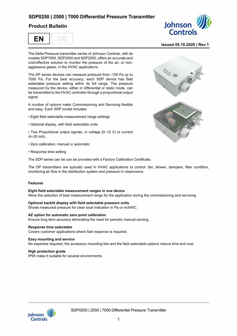
The Delta Pressure transmitter series of Johnson Controls, with its models SDP7000, SDP2500 and SDP2050, offers an accurate and cost-effective solution to monitor the pressure of the air, or non-aggressive gases, in the HVAC applications.
The DP series devices can measure pressure from -150 Pa up to 7000 Pa. For the best accuracy, each SDP device has field selectable pressure setting within its full range. The pressure measured by the device, either in differential or static mode, can be transmitted to the HVAC controller through a proportional output signal.
A number of options make Commissioning and Servicing flexible and easy. Each SDP model includes:
• Eight field selectable measurement range settings
• Optional display, with field selectable units
• Two Proportional output signals, in voltage (0–10 V) or current (4–20 mA).
• Zero calibration, manual or automatic
• Response time setting
The SDP series can be can be provided with a Factory Calibration Certificate.
The DP transmitters are typically used in HVAC applications to control: fan, blower, dampers, filter condition, monitoring air flow in the distribution system and pressure in cleanrooms.
Features
Eight field selectable measurement ranges in one device Allow the selection of best measurement range for the application during the commissioning and servicing.
Optional backlit display with field selectable pressure units Shows measured pressure for clear local indication in Pa or inchWC.
AZ option for automatic zero point calibration Ensure long term accuracy eliminating the need for periodic manual zeroing.
Response time selectable Covers customer applications where fast response is required.
Easy mounting and service No expertise required, the accessory mounting kits and the field selectable options reduce time and cost.
High protection grade IP65 make it suitable for several environments
SDP0250 | 2500 | 7000 Differential Pressure Transmitter
2
Enclosure with UV and weather protection
After some time, outdoor mounted plastics can lose their color and quality. Therefore, all hinged cover enclosures are made of special white polycarbonate (PC). The light-stable colorants and additives are used to achieve optimum protection of the polymer while maintaining color stability. The titanium dioxide used is especially developed for polycarbonate and offers excellent UV protection through the reflection of the entire light spectrum including the UV component around 340 nm. This effectively counteracts the otherwise occurring photochemical polymer degradation. The color intensity is preserved for a long time without fading. The material is also resistant to cold and frost.
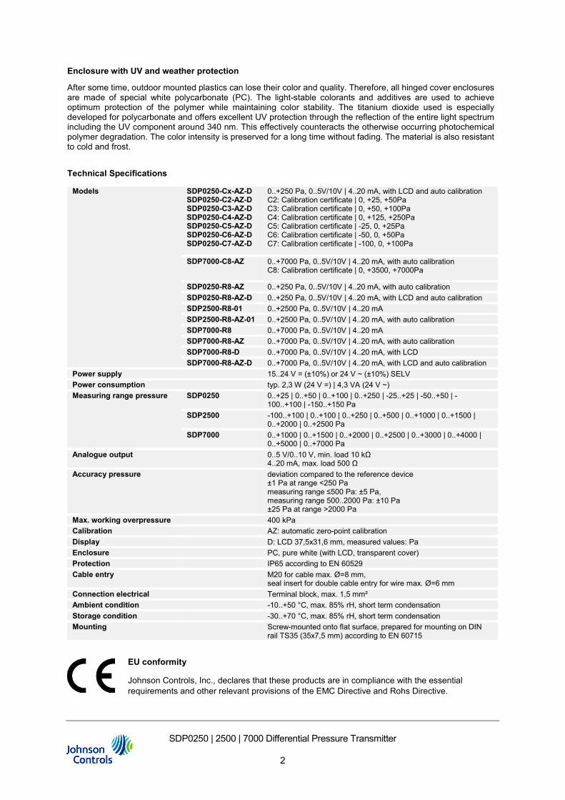
Technical Specifications
Models SDP0250-Cx-AZ-D SDP0250-C2-AZ-D SDP0250-C3-AZ-D SDP0250-C4-AZ-D SDP0250-C5-AZ-D SDP0250-C6-AZ-D SDP0250-C7-AZ-D
0..+250 Pa, 0..5V/10V | 4..20 mA, with LCD and auto calibration C2: Calibration certificate | 0, +25, +50Pa C3: Calibration certificate | 0, +50, +100Pa C4: Calibration certificate | 0, +125, +250Pa C5: Calibration certificate | -25, 0, +25Pa C6: Calibration certificate | -50, 0, +50Pa C7: Calibration certificate | -100, 0, +100Pa
SDP7000-C8-AZ 0..+7000 Pa, 0..5V/10V | 4..20 mA, with auto calibration C8: Calibration certificate | 0, +3500, +7000Pa
SDP0250-R8-AZ 0..+250 Pa, 0..5V/10V | 4..20 mA, with auto calibration SDP0250-R8-AZ-D 0..+250 Pa, 0..5V/10V | 4..20 mA, with LCD and auto calibration SDP2500-R8-01 0..+2500 Pa, 0..5V/10V | 4..20 mA SDP2500-R8-AZ-01 0..+2500 Pa, 0..5V/10V | 4..20 mA, with auto calibration SDP7000-R8 0..+7000 Pa, 0..5V/10V | 4..20 mA SDP7000-R8-AZ 0..+7000 Pa, 0..5V/10V | 4..20 mA, with auto calibration SDP7000-R8-D 0..+7000 Pa, 0..5V/10V | 4..20 mA, with LCD SDP7000-R8-AZ-D 0..+7000 Pa, 0..5V/10V | 4..20 mA, with LCD and auto calibration
Power supply 15..24 V = (±10%) or 24 V ~ (±10%) SELV Power consumption typ. 2,3 W (24 V =) | 4,3 VA (24 V ~) Measuring range pressure SDP0250 0..+25 | 0..+50 | 0..+100 | 0..+250 | -25..+25 | -50..+50 | -
100..+100 | -150..+150 Pa SDP2500 -100..+100 | 0..+100 | 0..+250 | 0..+500 | 0..+1000 | 0..+1500 |
0..+2000 | 0..+2500 Pa SDP7000 0..+1000 | 0..+1500 | 0..+2000 | 0..+2500 | 0..+3000 | 0..+4000 |
0..+5000 | 0..+7000 Pa Analogue output 0..5 V/0..10 V, min. load 10 kΩ
4..20 mA, max. load 500 Ω Accuracy pressure deviation compared to the reference device
±1 Pa at range <250 Pa measuring range ≤500 Pa: ±5 Pa, measuring range 500..2000 Pa: ±10 Pa ±25 Pa at range >2000 Pa
Max. working overpressure 400 kPa Calibration AZ: automatic zero-point calibration Display D: LCD 37,5x31,6 mm, measured values: Pa Enclosure PC, pure white (with LCD, transparent cover) Protection IP65 according to EN 60529 Cable entry M20 for cable max. Ø=8 mm,
seal insert for double cable entry for wire max. Ø=6 mm Connection electrical Terminal block, max. 1,5 mm² Ambient condition -10..+50 °C, max. 85% rH, short term condensation Storage condition -30..+70 °C, max. 85% rH, short term condensation Mounting Screw-mounted onto flat surface, prepared for mounting on DIN
rail TS35 (35x7,5 mm) according to EN 60715
EU conformity
Johnson Controls, Inc., declares that these products are in compliance with the essential requirements and other relevant provisions of the EMC Directive and Rohs Directive.
SDP0250 | 2500 | 7000 Differential Pressure Transmitter
3
Ordering Codes
Single Pack
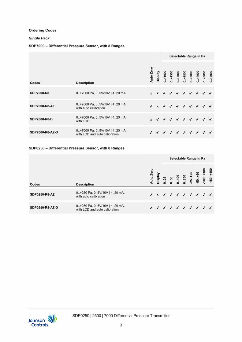
SDP7000 – Differential Pressure Sensor, with 8 Ranges
Codes Description Aut
o Ze
ro
Dis
play
Selectable Range in Pa
0..+
1000
0.
.+15
00
0..+
2000
0..+
2500
0..+
3000
0..+
4000
0..+
5000
0..+
7000
SDP7000-R8 0..+7000 Pa, 0..5V/10V | 4..20 mA x x ✔ ✔ ✔ ✔ ✔ ✔ ✔ ✔
SDP7000-R8-AZ 0..+7000 Pa, 0..5V/10V | 4..20 mA, with auto calibration ✔ x ✔ ✔ ✔ ✔ ✔ ✔ ✔ ✔
SDP7000-R8-D 0..+7000 Pa, 0..5V/10V | 4..20 mA, with LCD x ✔ ✔ ✔ ✔ ✔ ✔ ✔ ✔ ✔
SDP7000-R8-AZ-D 0..+7000 Pa, 0..5V/10V | 4..20 mA, with LCD and auto calibration ✔ ✔ ✔ ✔ ✔ ✔ ✔ ✔ ✔ ✔
SDP0250 – Differential Pressure Sensor, with 8 Ranges
Codes Description Aut
o Ze
ro
Dis
play
Selectable Range in Pa
0..2
5
0..5
0
0..1
00
0..2
50
-25.
.+25
-50.
.+50
-100
..+10
0
-150
..+15
0
SDP0250-R8-AZ 0..+250 Pa, 0..5V/10V | 4..20 mA, with auto calibration ✔ x ✔ ✔ ✔ ✔ ✔ ✔ ✔ ✔
SDP0250-R8-AZ-D 0..+250 Pa, 0..5V/10V | 4..20 mA, with LCD and auto calibration ✔ ✔ ✔ ✔ ✔ ✔ ✔ ✔ ✔ ✔
SDP0250 | 2500 | 7000 Differential Pressure Transmitter
4
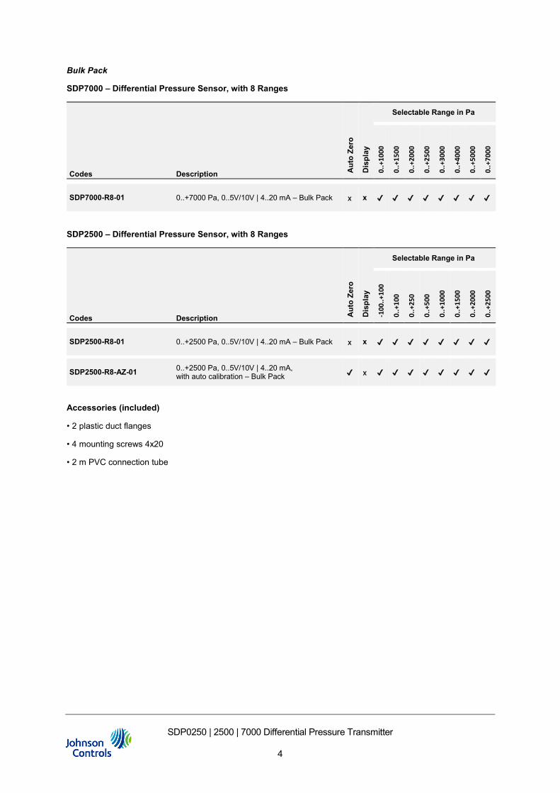
Bulk Pack
SDP7000 – Differential Pressure Sensor, with 8 Ranges
Codes Description Aut
o Ze
ro
Dis
play
Selectable Range in Pa
0..+
1000
0.
.+15
00
0..+
2000
0..+
2500
0..+
3000
0..+
4000
0..+
5000
0..+
7000
SDP7000-R8-01 0..+7000 Pa, 0..5V/10V | 4..20 mA – Bulk Pack x x ✔ ✔ ✔ ✔ ✔ ✔ ✔ ✔
SDP2500 – Differential Pressure Sensor, with 8 Ranges
Codes Description Aut
o Ze
ro
Dis
play
Selectable Range in Pa
-100
..+10
0
0..+
100
0..+
250
0..+
500
0..+
1000
0..+
1500
0..+
2000
0..+
2500
SDP2500-R8-01 0..+2500 Pa, 0..5V/10V | 4..20 mA – Bulk Pack x x ✔ ✔ ✔ ✔ ✔ ✔ ✔ ✔
SDP2500-R8-AZ-01 0..+2500 Pa, 0..5V/10V | 4..20 mA, with auto calibration – Bulk Pack ✔ x ✔ ✔ ✔ ✔ ✔ ✔ ✔ ✔
Accessories (included)
• 2 plastic duct flanges
• 4 mounting screws 4x20
• 2 m PVC connection tube
SDP0250 | 2500 | 7000 Differential Pressure Transmitter
5
Inspection certificate 3.1 accroding to EN 10204
On request, the SDP transmitter can be provided with a inspection certificate for a specific pressure range setting.
The certificate will report:
• Date and validity
• Device type and calibration range
• Device ID
• Test report on 3 measurement points
The calibration test performed in the factory ensures the accuracy of the pressure readings measured by the sensor. A calibration certificate is provided with any error measured in the test declared. This error value can be used when configuring the analog input channel for the sensor. Select the error at the nearest value the pressure sensors is expected to be typically measuring, this should normally be mid-range, and use this as the offset when setting up the analog input channel. This will ensure the sensor provides the greatest accuracy possible at the normal operating condition.
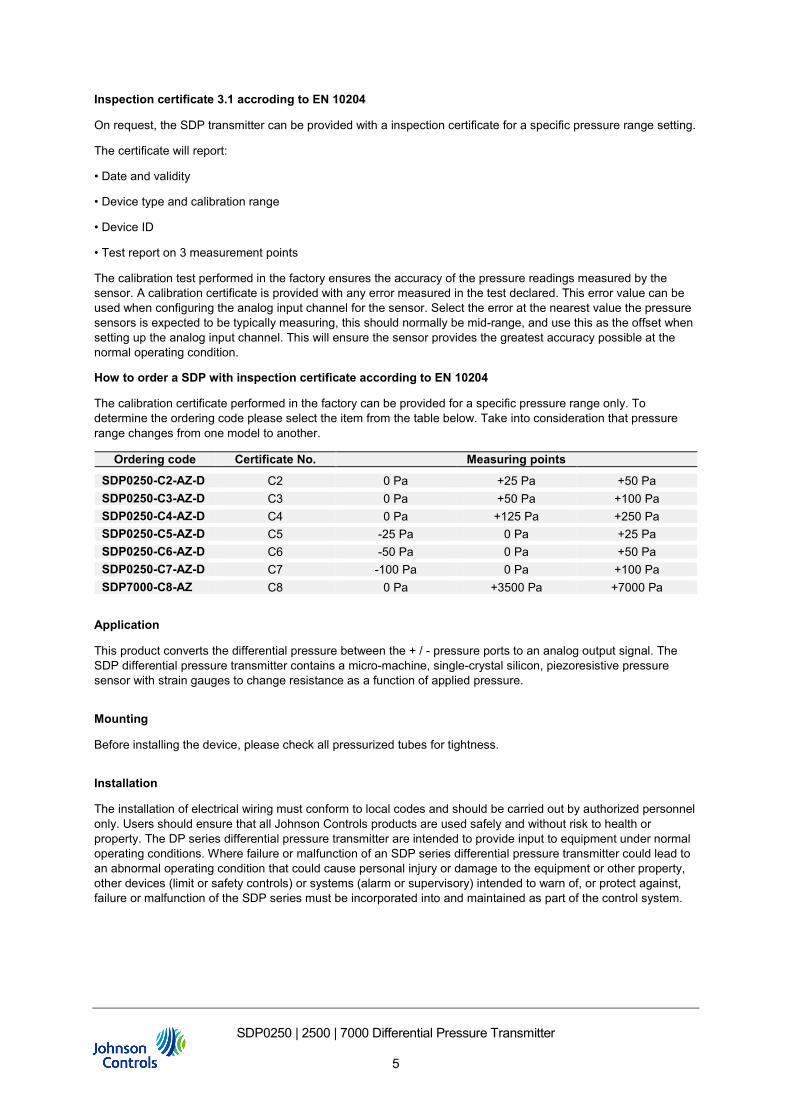
How to order a SDP with inspection certificate according to EN 10204
The calibration certificate performed in the factory can be provided for a specific pressure range only. To determine the ordering code please select the item from the table below. Take into consideration that pressure range changes from one model to another.
Ordering code Certificate No. Measuring points
SDP0250-C2-AZ-D C2 0 Pa +25 Pa +50 Pa SDP0250-C3-AZ-D C3 0 Pa +50 Pa +100 Pa SDP0250-C4-AZ-D C4 0 Pa +125 Pa +250 Pa SDP0250-C5-AZ-D C5 -25 Pa 0 Pa +25 Pa SDP0250-C6-AZ-D C6 -50 Pa 0 Pa +50 Pa SDP0250-C7-AZ-D C7 -100 Pa 0 Pa +100 Pa SDP7000-C8-AZ C8 0 Pa +3500 Pa +7000 Pa
Application
This product converts the differential pressure between the + / - pressure ports to an analog output signal. The SDP differential pressure transmitter contains a micro-machine, single-crystal silicon, piezoresistive pressure sensor with strain gauges to change resistance as a function of applied pressure.
Mounting
Before installing the device, please check all pressurized tubes for tightness.
Installation
The installation of electrical wiring must conform to local codes and should be carried out by authorized personnel only. Users should ensure that all Johnson Controls products are used safely and without risk to health or property. The DP series differential pressure transmitter are intended to provide input to equipment under normal operating conditions. Where failure or malfunction of an SDP series differential pressure transmitter could lead to an abnormal operating condition that could cause personal injury or damage to the equipment or other property, other devices (limit or safety controls) or systems (alarm or supervisory) intended to warn of, or protect against, failure or malfunction of the SDP series must be incorporated into and maintained as part of the control system.
SDP0250 | 2500 | 7000 Differential Pressure Transmitter
6
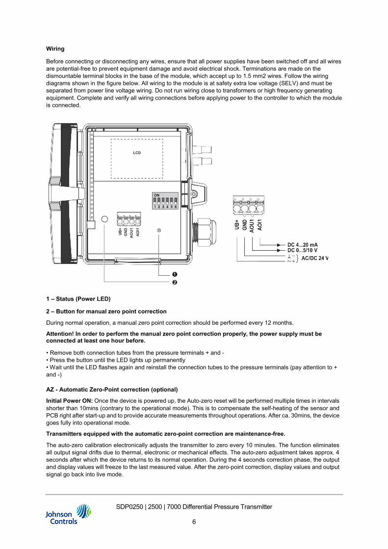
Wiring
Before connecting or disconnecting any wires, ensure that all power supplies have been switched off and all wires are potential-free to prevent equipment damage and avoid electrical shock. Terminations are made on the dismountable terminal blocks in the base of the module, which accept up to 1.5 mm2 wires. Follow the wiring diagrams shown in the figure below. All wiring to the module is at safety extra low voltage (SELV) and must be separated from power line voltage wiring. Do not run wiring close to transformers or high frequency generating equipment. Complete and verify all wiring connections before applying power to the controller to which the module is connected.
1 – Status (Power LED)
2 – Button for manual zero point correction
During normal operation, a manual zero point correction should be performed every 12 months.
Attention! In order to perform the manual zero point correction properly, the power supply must be connected at least one hour before.
• Remove both connection tubes from the pressure terminals + and - • Press the button until the LED lights up permanently • Wait until the LED flashes again and reinstall the connection tubes to the pressure terminals (pay attention to + and -)
AZ - Automatic Zero-Point correction (optional)
Initial Power ON: Once the device is powered up, the Auto-zero reset will be performed multiple times in intervals shorter than 10mins (contrary to the operational mode). This is to compensate the self-heating of the sensor and PCB right after start-up and to provide accurate measurements throughout operations. After ca. 30mins, the device goes fully into operational mode.
Transmitters equipped with the automatic zero-point correction are maintenance-free.
The auto-zero calibration electronically adjusts the transmitter to zero every 10 minutes. The function eliminates all output signal drifts due to thermal, electronic or mechanical effects. The auto-zero adjustment takes approx. 4 seconds after which the device returns to its normal operation. During the 4 seconds correction phase, the output and display values will freeze to the last measured value. After the zero-point correction, display values and output signal go back into live mode.
SDP0250 | 2500 | 7000 Differential Pressure Transmitter
7
Operation
Selecting Pressure Range
DIP settings
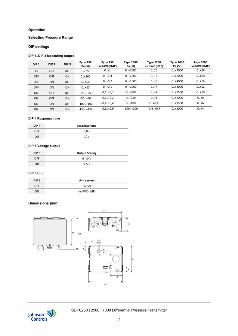
DIP 1..DIP 3 Measuring ranges
DIP 1 DIP 2 DIP 3 Type 250 Pa (SI)
Type 250 inchWC (IMP)
Type 2500 Pa (SI)
Type 2500 inchWC (IMP)
Type 7000 Pa (SI)
Type 7000 inchWC (IMP)
OFF OFF OFF 0..+250 0..+1 0..+2500 0..10 0..+7000 0..+28
OFF OFF ON 0..+100 0..+0,4 0..+2000 0..+8 0..+5000 0..+20
OFF ON OFF 0..+50 0..+0,2 0..+1500 0..+6 0..+4000 0..+16
OFF ON ON 0..+25 0..+0,1 0..+1000 0..+4 0..+3000 0..+12
ON OFF OFF -25..+25 -0,1..+0,1 0..+500 0..+2 0..+2500 0..+10
ON OFF ON -50..+50 -0,2..+0,2 0..+250 0..+1 0..+2000 0..+8
ON ON OFF -100..+100 -0,4..+0,4 0..+100 0..+0,4 0..+1500 0..+6
ON ON ON -150..+150 -0,6..+0,6 -100..+100 -0,4..+0,4 0..+1000 0..+4
DIP 4 Response time
DIP 4 Response time
OFF 0,8 s
ON 10 s
DIP 5 Voltage output
DIP 5 Output Scaling
OFF 0..10 V
ON 0..5 V
DIP 6 Unit
DIP 5 Unit system
OFF Pa (SI)
ON inchWC (IMP)
Dimensions (mm)
SDP0250 | 2500 | 7000 Differenzdruck-Messumformer
Produkt Bulletin
Stand 05.10.2020 | Rev.1
SDP0250 | 2500 | 7000 Differenzdruck-Messumformer
8
EN DE
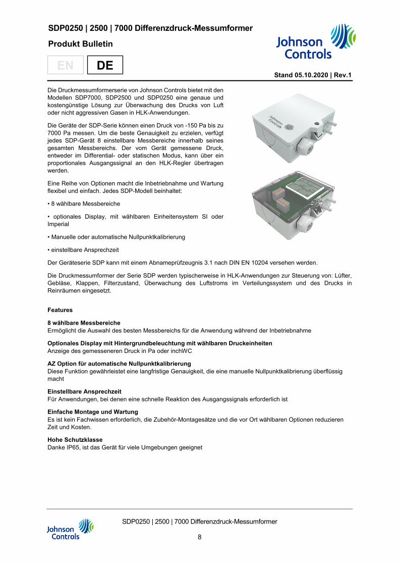
Die Druckmessumformerserie von Johnson Controls bietet mit den Modellen SDP7000, SDP2500 und SDP0250 eine genaue und kostengünstige Lösung zur Überwachung des Drucks von Luft oder nicht aggressiven Gasen in HLK-Anwendungen.
Die Geräte der SDP-Serie können einen Druck von -150 Pa bis zu 7000 Pa messen. Um die beste Genauigkeit zu erzielen, verfügt jedes SDP-Gerät 8 einstellbare Messbereiche innerhalb seines gesamten Messbereichs. Der vom Gerät gemessene Druck, entweder im Differential- oder statischen Modus, kann über ein proportionales Ausgangssignal an den HLK-Regler übertragen werden.
Eine Reihe von Optionen macht die Inbetriebnahme und Wartung flexibel und einfach. Jedes SDP-Modell beinhaltet:
• 8 wählbare Messbereiche
• optionales Display, mit wählbaren Einheitensystem SI oder Imperial
• Manuelle oder automatische Nullpunktkalibrierung
• einstellbare Ansprechzeit
Der Geräteserie SDP kann mit einem Abnameprüfzeugnis 3.1 nach DIN EN 10204 versehen werden.
Die Druckmessumformer der Serie SDP werden typischerweise in HLK-Anwendungen zur Steuerung von: Lüfter, Gebläse, Klappen, Filterzustand, Überwachung des Luftstroms im Verteilungssystem und des Drucks in Reinräumen eingesetzt.
Features
8 wählbare Messbereiche Ermöglicht die Auswahl des besten Messbereichs für die Anwendung während der Inbetriebnahme
Optionales Display mit Hintergrundbeleuchtung mit wählbaren Druckeinheiten Anzeige des gemesseneren Druck in Pa oder inchWC
AZ Option für automatische Nullpunktkalibrierung Diese Funktion gewährleistet eine langfristige Genauigkeit, die eine manuelle Nullpunktkalibrierung überflüssig macht
Einstellbare Ansprechzeit Für Anwendungen, bei denen eine schnelle Reaktion des Ausgangssignals erforderlich ist
Einfache Montage und Wartung Es ist kein Fachwissen erforderlich, die Zubehör-Montagesätze und die vor Ort wählbaren Optionen reduzieren Zeit und Kosten.
Hohe Schutzklasse Danke IP65, ist das Gerät für viele Umgebungen geeignet
SDP0250 | 2500 | 7000 Differenzdruck-Messumformer
9
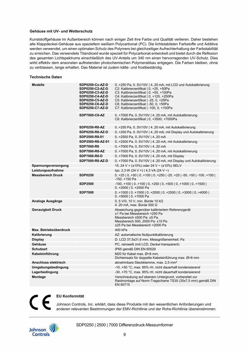
Gehäuse mit UV- und Wetterschutz
Kunststoffgehäuse im Außenbereich können nach einiger Zeit ihre Farbe und Qualität verlieren. Daher bestehen alle Klappdeckel-Gehäuse aus speziellem weißem Polycarbonat (PC). Die lichtstabilsten Farbstoffe und Additive werden verwendet, um einen optimalen Schutz des Polymers bei gleichzeitiger Aufrechterhaltung der Farbstabilität zu erreichen. Das verwendete Titandioxid wurde speziell für Polycarbonat entwickelt und bietet durch die Reflexion des gesamten Lichtspektrums einschließlich des UV-Anteils um 340 nm einen hervorragenden UV-Schutz. Dies wirkt effektiv dem ansonsten auftretenden photochemischen Polymerabbau entgegen. Die Farben bleiben, ohne zu verblassen, lange erhalten. Das Material ist zudem kälte- und frostbeständig.
Technische Daten
Modelle SDP0250-Cx-AZ-D SDP0250-C2-AZ-D SDP0250-C3-AZ-D SDP0250-C4-AZ-D SDP0250-C5-AZ-D SDP0250-C6-AZ-D SDP0250-C7-AZ-D
0..+250 Pa, 0..5V/10V | 4..20 mA, mit LCD und Autokalibrierung C2: Kalibrierzertifikat | 0, +25, +50Pa C3: Kalibrierzertifikat | 0, +50, +100Pa C4: Kalibrierzertifikat | 0, +125, +250Pa C5: Kalibrierzertifikat | -25, 0, +25Pa C6: Kalibrierzertifikat | -50, 0, +50Pa C7: Kalibrierzertifikat | -100, 0, +100Pa
SDP7000-C8-AZ 0..+7000 Pa, 0..5V/10V | 4..20 mA, mit Autokalibrierung C8: Kalibrierzertifikat | 0, +3500, +7000Pa
SDP0250-R8-AZ 0..+250 Pa, 0..5V/10V | 4..20 mA, mit Autokalibrierung SDP0250-R8-AZ-D 0..+250 Pa, 0..5V/10V | 4..20 mA, mit Display und Autokalibrierung SDP2500-R8-01 0..+2500 Pa, 0..5V/10V | 4..20 mA SDP2500-R8-AZ-01 0..+2500 Pa, 0..5V/10V | 4..20 mA, mit Autokalibrierung SDP7000-R8 0..+7000 Pa, 0..5V/10V | 4..20 mA SDP7000-R8-AZ 0..+7000 Pa, 0..5V/10V | 4..20 mA, mit Autokalibrierung SDP7000-R8-D 0..+7000 Pa, 0..5V/10V | 4..20 mA, mit Display SDP7000-R8-AZ-D 0..+7000 Pa, 0..5V/10V | 4..20 mA, mit Display und Autokalibrierung
Spannungsversorgung 15..24 V = (±10%) oder 24 V ~ (±10%) SELV Leistungsaufnahme typ. 2,3 W (24 V =) | 4,3 VA (24 V ~) Messbereich Druck SDP0250 0..+25 | 0..+50 | 0..+100 | 0..+250 | -25..+25 | -50..+50 | -100..+100 |
-150..+150 Pa SDP2500 -100..+100 | 0..+100 | 0..+250 | 0..+500 | 0..+1000 | 0..+1500 |
0..+2000 | 0..+2500 Pa SDP7000 0..+1000 | 0..+1500 | 0..+2000 | 0..+2500 | 0..+3000 | 0..+4000 |
0..+5000 | 0..+7000 Pa Analoge Ausgänge 0..5 V/0..10 V, min. Bürde 10 kΩ
4..20 mA, max. Bürde 500 Ω Genauigkeit Druck Abweichung gegenüber kalibriertem Referenzgerät
±1 Pa bei Messbereich <250 Pa Messbereich ≤500 Pa: ±5 Pa, Messbereich 500..2000 Pa: ±10 Pa ±25 Pa bei Messbereich >2000 Pa
Max. Betriebsüberdruck 400 kPa Kalibrierung AZ: automatische Nullpunktkalibrierung Display D: LCD 37,5x31,6 mm, Messgrößeneinheit: Pa Gehäuse PC, reinweiß (mit LCD, Deckel transparent) Schutzart IP65 gemäß DIN EN 60529 Kabeleinführung M20 für Kabel max. Ø=8 mm,
Dichteinsatz für doppelte Kabeleinführung max. Ø=6 mm Anschluss elektrisch abnehmbare Steckklemme, max. 2,5 mm² Umgebungsbedingung -10..+50 °C, max. 85% rH, nicht dauerhaft kondensierend Lagerbedingung -30..+70 °C, max. 85% rH, nicht dauerhaft kondensierend Montage Verschraubung auf ebenem Untergrund, vorbereitet zur
Rastmontage auf Norm-Tragschiene TS35 (35x7,5 mm) gemäß DIN EN 60715
EU Konformität
Johnson Controls, Inc. erklärt, dass diese Produkte mit den wesentlichen Anforderungen und anderen relevanten Bestimmungen der EMV-Richtlinie und der Rohs-Richtlinie übereinstimmen.
SDP0250 | 2500 | 7000 Differenzdruck-Messumformer
10
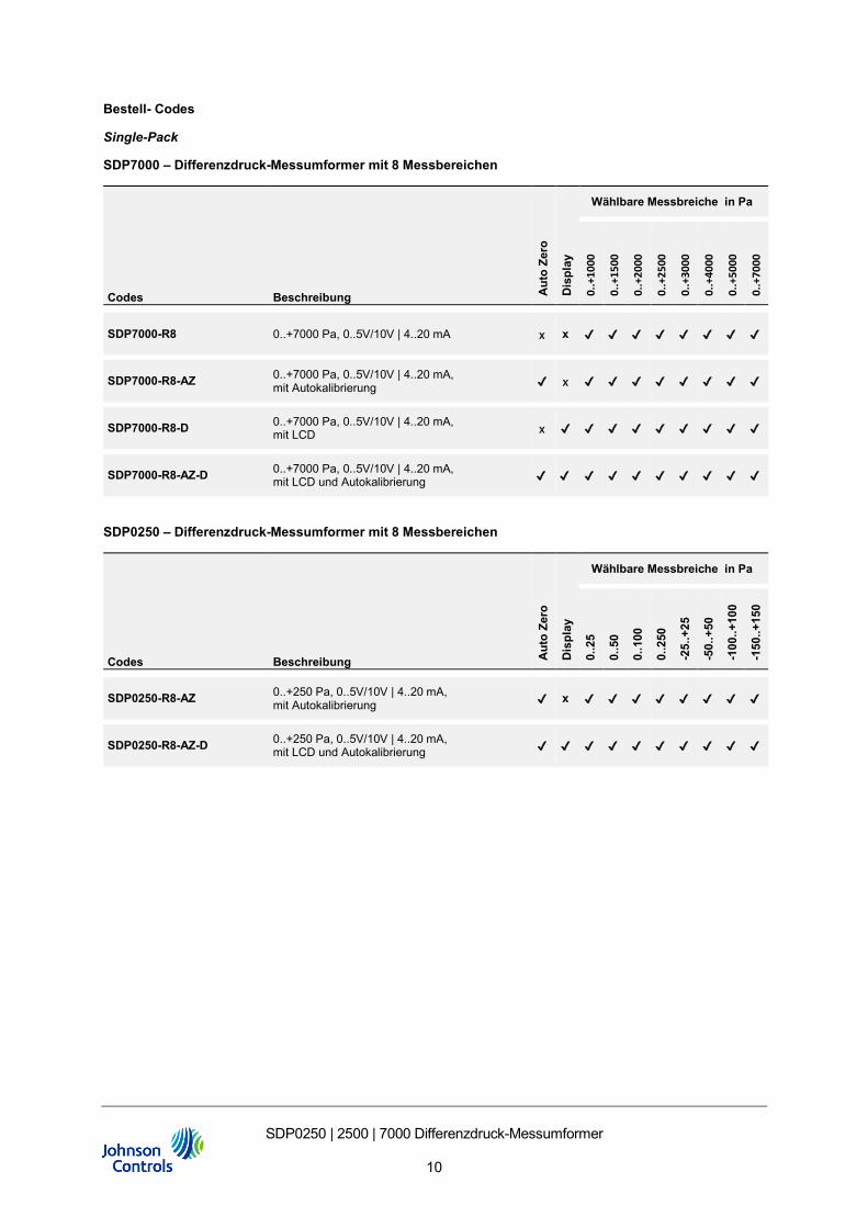
Bestell- Codes
Single-Pack
SDP7000 – Differenzdruck-Messumformer mit 8 Messbereichen
Codes Beschreibung Aut
o Ze
ro
Dis
play
Wählbare Messbreiche in Pa
0..+
1000
0.
.+15
00
0..+
2000
0..+
2500
0..+
3000
0..+
4000
0..+
5000
0..+
7000
SDP7000-R8 0..+7000 Pa, 0..5V/10V | 4..20 mA x x ✔ ✔ ✔ ✔ ✔ ✔ ✔ ✔
SDP7000-R8-AZ 0..+7000 Pa, 0..5V/10V | 4..20 mA, mit Autokalibrierung ✔ x ✔ ✔ ✔ ✔ ✔ ✔ ✔ ✔
SDP7000-R8-D 0..+7000 Pa, 0..5V/10V | 4..20 mA, mit LCD x ✔ ✔ ✔ ✔ ✔ ✔ ✔ ✔ ✔
SDP7000-R8-AZ-D 0..+7000 Pa, 0..5V/10V | 4..20 mA, mit LCD und Autokalibrierung ✔ ✔ ✔ ✔ ✔ ✔ ✔ ✔ ✔ ✔
SDP0250 – Differenzdruck-Messumformer mit 8 Messbereichen
Codes Beschreibung Aut
o Ze
ro
Dis
play
Wählbare Messbreiche in Pa
0..2
5
0..5
0
0..1
00
0..2
50
-25.
.+25
-50.
.+50
-100
..+10
0
-150
..+15
0
SDP0250-R8-AZ 0..+250 Pa, 0..5V/10V | 4..20 mA, mit Autokalibrierung ✔ x ✔ ✔ ✔ ✔ ✔ ✔ ✔ ✔
SDP0250-R8-AZ-D 0..+250 Pa, 0..5V/10V | 4..20 mA, mit LCD und Autokalibrierung ✔ ✔ ✔ ✔ ✔ ✔ ✔ ✔ ✔ ✔
SDP0250 | 2500 | 7000 Differenzdruck-Messumformer
11
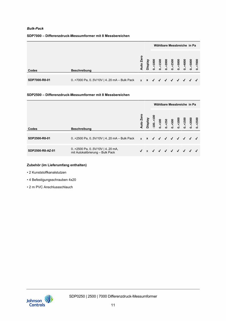
Bulk-Pack
SDP7000 – Differenzdruck-Messumformer mit 8 Messbereichen
Codes Beschreibung Aut
o Ze
ro
Dis
play
Wählbare Messbreiche in Pa
0..+
1000
0.
.+15
00
0..+
2000
0..+
2500
0..+
3000
0..+
4000
0..+
5000
0..+
7000
SDP7000-R8-01 0..+7000 Pa, 0..5V/10V | 4..20 mA – Bulk Pack x x ✔ ✔ ✔ ✔ ✔ ✔ ✔ ✔
SDP2500 – Differenzdruck-Messumformer mit 8 Messbereichen
Codes Beschreibung Aut
o Ze
ro
Dis
play
Wählbare Messbreiche in Pa
-100
..+10
0
0..+
100
0..+
250
0..+
500
0..+
1000
0..+
1500
0..+
2000
0..+
2500
SDP2500-R8-01 0..+2500 Pa, 0..5V/10V | 4..20 mA – Bulk Pack x x ✔ ✔ ✔ ✔ ✔ ✔ ✔ ✔
SDP2500-R8-AZ-01 0..+2500 Pa, 0..5V/10V | 4..20 mA, mit Autokalibrierung – Bulk Pack ✔ x ✔ ✔ ✔ ✔ ✔ ✔ ✔ ✔
Zubehör (im Lieferumfang enthalten)
• 2 Kunststoffkanalstutzen
• 4 Befestigungsschrauben 4x20
• 2 m PVC Anschlussschlauch
SDP0250 | 2500 | 7000 Differenzdruck-Messumformer
12
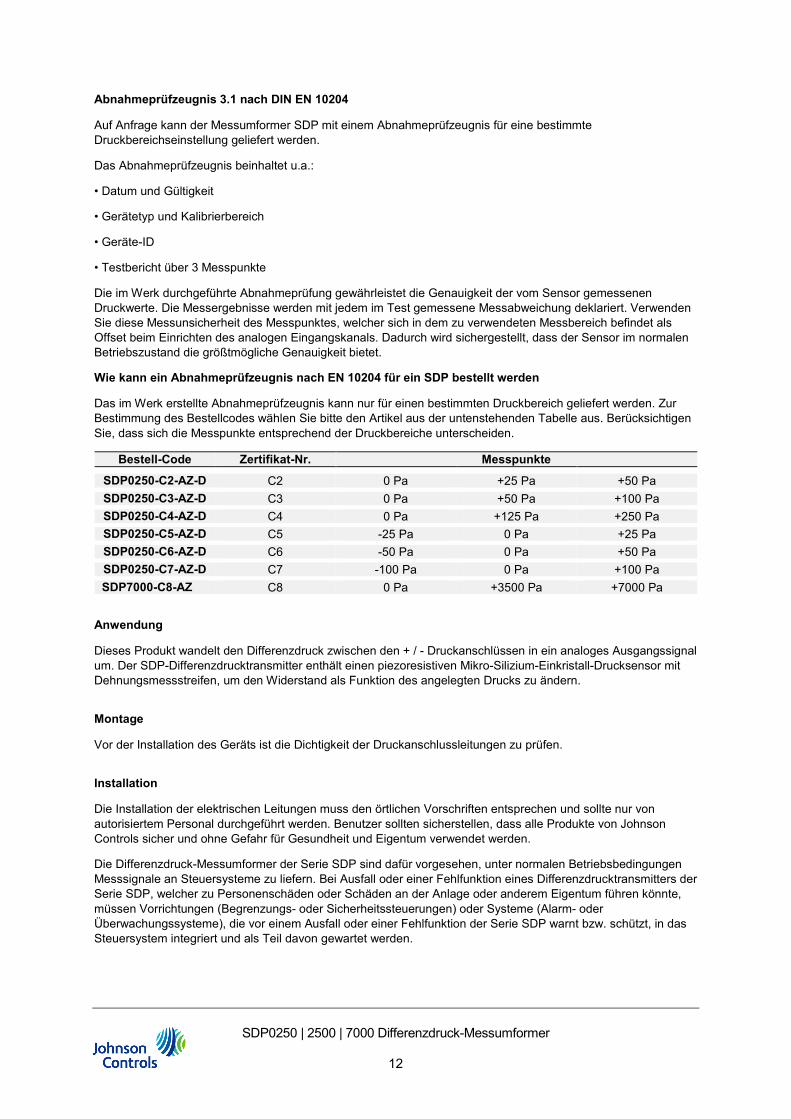
Abnahmeprüfzeugnis 3.1 nach DIN EN 10204
Auf Anfrage kann der Messumformer SDP mit einem Abnahmeprüfzeugnis für eine bestimmte Druckbereichseinstellung geliefert werden.
Das Abnahmeprüfzeugnis beinhaltet u.a.:
• Datum und Gültigkeit
• Gerätetyp und Kalibrierbereich
• Geräte-ID
• Testbericht über 3 Messpunkte
Die im Werk durchgeführte Abnahmeprüfung gewährleistet die Genauigkeit der vom Sensor gemessenen Druckwerte. Die Messergebnisse werden mit jedem im Test gemessene Messabweichung deklariert. Verwenden Sie diese Messunsicherheit des Messpunktes, welcher sich in dem zu verwendeten Messbereich befindet als Offset beim Einrichten des analogen Eingangskanals. Dadurch wird sichergestellt, dass der Sensor im normalen Betriebszustand die größtmögliche Genauigkeit bietet.
Wie kann ein Abnahmeprüfzeugnis nach EN 10204 für ein SDP bestellt werden
Das im Werk erstellte Abnahmeprüfzeugnis kann nur für einen bestimmten Druckbereich geliefert werden. Zur Bestimmung des Bestellcodes wählen Sie bitte den Artikel aus der untenstehenden Tabelle aus. Berücksichtigen Sie, dass sich die Messpunkte entsprechend der Druckbereiche unterscheiden.
Bestell-Code Zertifikat-Nr. Messpunkte
SDP0250-C2-AZ-D C2 0 Pa +25 Pa +50 Pa SDP0250-C3-AZ-D C3 0 Pa +50 Pa +100 Pa SDP0250-C4-AZ-D C4 0 Pa +125 Pa +250 Pa SDP0250-C5-AZ-D C5 -25 Pa 0 Pa +25 Pa SDP0250-C6-AZ-D C6 -50 Pa 0 Pa +50 Pa SDP0250-C7-AZ-D C7 -100 Pa 0 Pa +100 Pa SDP7000-C8-AZ C8 0 Pa +3500 Pa +7000 Pa
Anwendung
Dieses Produkt wandelt den Differenzdruck zwischen den + / - Druckanschlüssen in ein analoges Ausgangssignal um. Der SDP-Differenzdrucktransmitter enthält einen piezoresistiven Mikro-Silizium-Einkristall-Drucksensor mit Dehnungsmessstreifen, um den Widerstand als Funktion des angelegten Drucks zu ändern.
Montage
Vor der Installation des Geräts ist die Dichtigkeit der Druckanschlussleitungen zu prüfen.
Installation
Die Installation der elektrischen Leitungen muss den örtlichen Vorschriften entsprechen und sollte nur von autorisiertem Personal durchgeführt werden. Benutzer sollten sicherstellen, dass alle Produkte von Johnson Controls sicher und ohne Gefahr für Gesundheit und Eigentum verwendet werden.
Die Differenzdruck-Messumformer der Serie SDP sind dafür vorgesehen, unter normalen Betriebsbedingungen Messsignale an Steuersysteme zu liefern. Bei Ausfall oder einer Fehlfunktion eines Differenzdrucktransmitters der Serie SDP, welcher zu Personenschäden oder Schäden an der Anlage oder anderem Eigentum führen könnte, müssen Vorrichtungen (Begrenzungs- oder Sicherheitssteuerungen) oder Systeme (Alarm- oder Überwachungssysteme), die vor einem Ausfall oder einer Fehlfunktion der Serie SDP warnt bzw. schützt, in das Steuersystem integriert und als Teil davon gewartet werden.
SDP0250 | 2500 | 7000 Differenzdruck-Messumformer
13
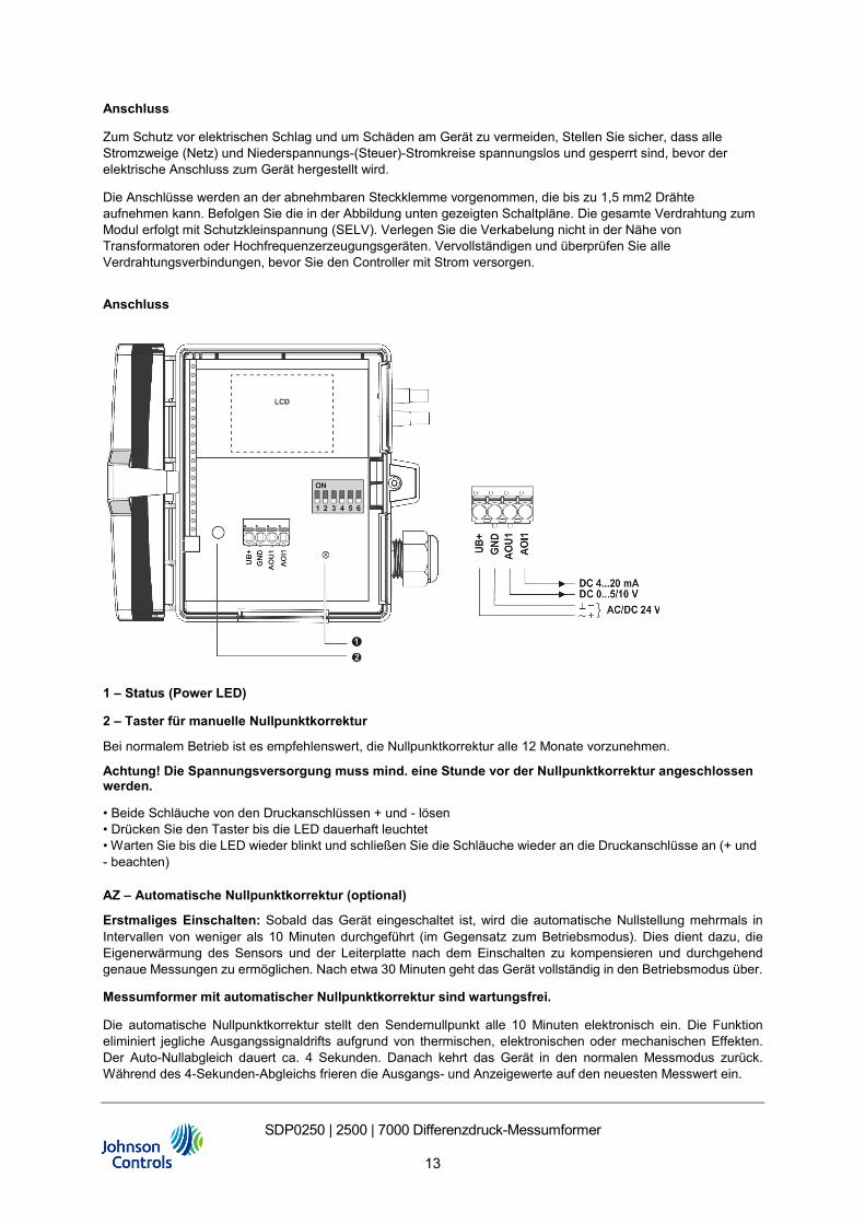
Anschluss
Zum Schutz vor elektrischen Schlag und um Schäden am Gerät zu vermeiden, Stellen Sie sicher, dass alle Stromzweige (Netz) und Niederspannungs-(Steuer)-Stromkreise spannungslos und gesperrt sind, bevor der elektrische Anschluss zum Gerät hergestellt wird.
Die Anschlüsse werden an der abnehmbaren Steckklemme vorgenommen, die bis zu 1,5 mm2 Drähte aufnehmen kann. Befolgen Sie die in der Abbildung unten gezeigten Schaltpläne. Die gesamte Verdrahtung zum Modul erfolgt mit Schutzkleinspannung (SELV). Verlegen Sie die Verkabelung nicht in der Nähe von Transformatoren oder Hochfrequenzerzeugungsgeräten. Vervollständigen und überprüfen Sie alle Verdrahtungsverbindungen, bevor Sie den Controller mit Strom versorgen.
Anschluss
1 – Status (Power LED)
2 – Taster für manuelle Nullpunktkorrektur
Bei normalem Betrieb ist es empfehlenswert, die Nullpunktkorrektur alle 12 Monate vorzunehmen.
Achtung! Die Spannungsversorgung muss mind. eine Stunde vor der Nullpunktkorrektur angeschlossen werden.
• Beide Schläuche von den Druckanschlüssen + und - lösen • Drücken Sie den Taster bis die LED dauerhaft leuchtet • Warten Sie bis die LED wieder blinkt und schließen Sie die Schläuche wieder an die Druckanschlüsse an (+ und - beachten)
AZ – Automatische Nullpunktkorrektur (optional)
Erstmaliges Einschalten: Sobald das Gerät eingeschaltet ist, wird die automatische Nullstellung mehrmals in Intervallen von weniger als 10 Minuten durchgeführt (im Gegensatz zum Betriebsmodus). Dies dient dazu, die Eigenerwärmung des Sensors und der Leiterplatte nach dem Einschalten zu kompensieren und durchgehend genaue Messungen zu ermöglichen. Nach etwa 30 Minuten geht das Gerät vollständig in den Betriebsmodus über.
Messumformer mit automatischer Nullpunktkorrektur sind wartungsfrei.
Die automatische Nullpunktkorrektur stellt den Sendernullpunkt alle 10 Minuten elektronisch ein. Die Funktion eliminiert jegliche Ausgangssignaldrifts aufgrund von thermischen, elektronischen oder mechanischen Effekten. Der Auto-Nullabgleich dauert ca. 4 Sekunden. Danach kehrt das Gerät in den normalen Messmodus zurück. Während des 4-Sekunden-Abgleichs frieren die Ausgangs- und Anzeigewerte auf den neuesten Messwert ein.
SDP0250 | 2500 | 7000 Differenzdruck-Messumformer
14
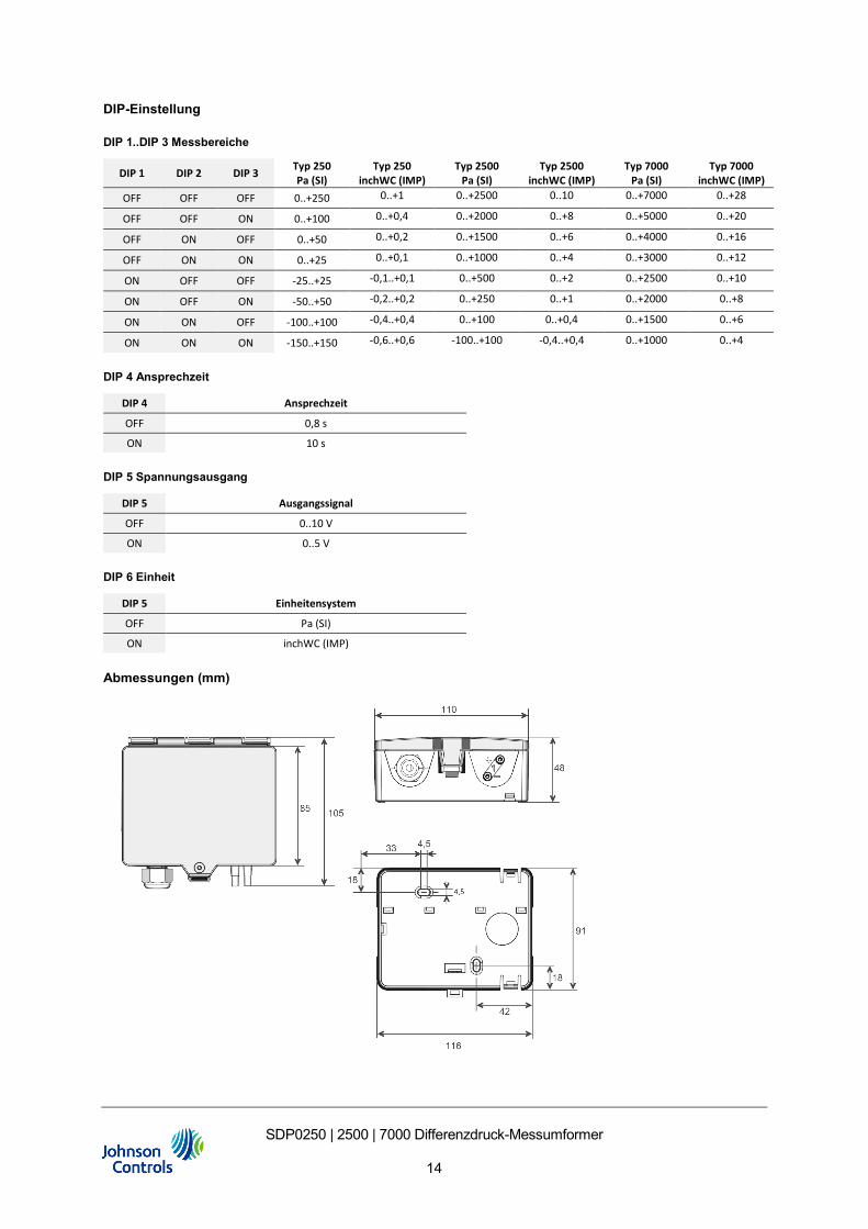
DIP-Einstellung
DIP 1..DIP 3 Messbereiche
DIP 1 DIP 2 DIP 3 Typ 250 Pa (SI)
Typ 250 inchWC (IMP)
Typ 2500 Pa (SI)
Typ 2500 inchWC (IMP)
Typ 7000 Pa (SI)
Typ 7000 inchWC (IMP)
OFF OFF OFF 0..+250 0..+1 0..+2500 0..10 0..+7000 0..+28
OFF OFF ON 0..+100 0..+0,4 0..+2000 0..+8 0..+5000 0..+20
OFF ON OFF 0..+50 0..+0,2 0..+1500 0..+6 0..+4000 0..+16
OFF ON ON 0..+25 0..+0,1 0..+1000 0..+4 0..+3000 0..+12
ON OFF OFF -25..+25 -0,1..+0,1 0..+500 0..+2 0..+2500 0..+10
ON OFF ON -50..+50 -0,2..+0,2 0..+250 0..+1 0..+2000 0..+8
ON ON OFF -100..+100 -0,4..+0,4 0..+100 0..+0,4 0..+1500 0..+6
ON ON ON -150..+150 -0,6..+0,6 -100..+100 -0,4..+0,4 0..+1000 0..+4
DIP 4 Ansprechzeit
DIP 4 Ansprechzeit
OFF 0,8 s
ON 10 s
DIP 5 Spannungsausgang
DIP 5 Ausgangssignal
OFF 0..10 V
ON 0..5 V
DIP 6 Einheit
DIP 5 Einheitensystem
OFF Pa (SI)
ON inchWC (IMP)
Abmessungen (mm)

SDP0250 | 2500 | 7000 Differenzdruck-Messumformer
15
European Single Point of Contact:
JOHNSON CONTROLS WESTENDHOF 3
45143 ESSEN GERMANY
www.johnsoncontrols.com
www.johnsoncontrols.com/locations
Metasys® and Johnson Controls® are registered trademarks of Johnson Controls. All other marks herein are the marks of their respective owners. © 2020 Johnson Controls.
SDP2500 Differential Pressure Transmitter
Product Bulletin
Issued 05.10.2020 | Rev.1
SDP2500 Differential Pressure Transmitter
1
EN DE
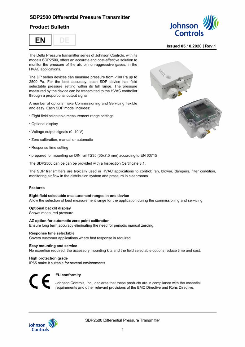
The Delta Pressure transmitter series of Johnson Controls, with its models SDP2500, offers an accurate and cost-effective solution to monitor the pressure of the air, or non-aggressive gases, in the HVAC applications.
The DP series devices can measure pressure from -100 Pa up to 2500 Pa. For the best accuracy, each SDP device has field selectable pressure setting within its full range. The pressure measured by the device can be transmitted to the HVAC controller through a proportional output signal.
A number of options make Commissioning and Servicing flexible and easy. Each SDP model includes:
• Eight field selectable measurement range settings
• Optional display
• Voltage output signals (0–10 V)
• Zero calibration, manual or automatic
• Response time setting
• prepared for mounting on DIN rail TS35 (35x7,5 mm) according to EN 60715
The SDP2500 can be can be provided with a Inspection Certificate 3.1.
The SDP transmitters are typically used in HVAC applications to control: fan, blower, dampers, filter condition, monitoring air flow in the distribution system and pressure in cleanrooms.
Features
Eight field selectable measurement ranges in one device Allow the selection of best measurement range for the application during the commissioning and servicing.
Optional backlit display Shows measured pressure
AZ option for automatic zero point calibration Ensure long term accuracy eliminating the need for periodic manual zeroing.
Response time selectable Covers customer applications where fast response is required.
Easy mounting and service No expertise required, the accessory mounting kits and the field selectable options reduce time and cost.
High protection grade IP65 make it suitable for several environments
EU conformity
Johnson Controls, Inc., declares that these products are in compliance with the essential requirements and other relevant provisions of the EMC Directive and Rohs Directive.
SDP2500 Differential Pressure Transmitter
2
Enclosure with UV and weather protection
After some time, outdoor mounted plastics can lose their color and quality. Therefore, all hinged cover enclosures are made of special white polycarbonate (PC). The light-stable colorants and additives are used to achieve optimum protection of the polymer while maintaining color stability. The titanium dioxide used is especially developed for polycarbonate and offers excellent UV protection through the reflection of the entire light spectrum including the UV component around 340 nm. This effectively counteracts the otherwise occurring photochemical polymer degradation. The color intensity is preserved for a long time without fading. The material is also resistant to cold and frost.
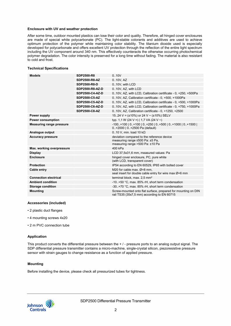
Technical Specifications
Models SDP2500-R8 0..10V SDP2500-R8-AZ 0..10V, AZ SDP2500-R8-D 0..10V, with LCD SDP2500-R8-AZ-D 0..10V, AZ, with LCD SDP2500-C4-AZ-D 0..10V, AZ, with LCD, Calibration certificate - 0, +250, +500Pa SDP2500-C5-AZ 0..10V, AZ, Calibration certificate - 0, +500, +1000Pa SDP2500-C5-AZ-D 0..10V, AZ, with LCD, Calibration certificate - 0, +500, +1000Pa SDP2500-C6-AZ-D 0..10V, AZ, with LCD, Calibration certificate - 0, +750, +1000Pa SDP2500-C8-AZ 0..10V, AZ, Calibration certificate - 0, +1250, +2500
Power supply 15..24 V = (±10%) or 24 V ~ (±10%) SELV Power consumption typ. 1,1 W (24 V =) | 1,7 VA (24 V ~) Measuring range pressure -100..+100 | 0..+100 | 0..+250 | 0..+500 | 0..+1000 | 0..+1500 |
0..+2000 | 0..+2500 Pa (default) Analogue output 0..10 V, min. load 10 kΩ Accuracy pressure deviation compared to the reference device
measuring range ≤500 Pa: ±5 Pa, measuring range >500 Pa: ±10 Pa
Max. working overpressure 400 kPa Display LCD 37,5x31,6 mm, measured values: Pa Enclosure hinged cover enclosure, PC, pure white
(with LCD, transparent cover) Protection IP54 according to EN 60529, IP65 with bolted cover Cable entry M20 for cable max. Ø=8 mm,
seal insert for double cable entry for wire max Ø=6 mm Connection electrical terminal block, max. 2,5 mm² Ambient condition -10..+50 °C, max. 85% rH, short term condensation Storage condition -30..+70 °C, max. 85% rH, short term condensation Mounting Screw-mounted onto flat surface, prepared for mounting on DIN
rail TS35 (35x7,5 mm) according to EN 60715
Accessories (included)
• 2 plastic duct flanges
• 4 mounting screws 4x20
• 2 m PVC connection tube
Application
This product converts the differential pressure between the + / - pressure ports to an analog output signal. The SDP differential pressure transmitter contains a micro-machine, single-crystal silicon, piezoresistive pressure sensor with strain gauges to change resistance as a function of applied pressure.
Mounting
Before installing the device, please check all pressurized tubes for tightness.
SDP2500 Differential Pressure Transmitter
3
Ordering Codes
Single Pack
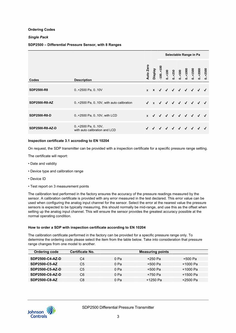
SDP2500 – Differential Pressure Sensor, with 8 Ranges
Codes Description Aut
o Ze
ro
Dis
play
Selectable Range in Pa
-100
..+10
0
0..+
100
0..+
250
0..+
500
0..+
1000
0..+
1500
0..+
2000
0..+
2500
SDP2500-R8 0..+2500 Pa, 0..10V x x ✔ ✔ ✔ ✔ ✔ ✔ ✔ ✔
SDP2500-R8-AZ 0..+2500 Pa, 0..10V, with auto calibration ✔ x ✔ ✔ ✔ ✔ ✔ ✔ ✔ ✔
SDP2500-R8-D 0..+2500 Pa, 0..10V, with LCD x ✔ ✔ ✔ ✔ ✔ ✔ ✔ ✔ ✔
SDP2500-R8-AZ-D 0..+2500 Pa, 0..10V, with auto calibration and LCD ✔ ✔ ✔ ✔ ✔ ✔ ✔ ✔ ✔ ✔
Inspection certificate 3.1 accroding to EN 10204
On request, the SDP transmitter can be provided with a inspection certificate for a specific pressure range setting.
The certificate will report:
• Date and validity
• Device type and calibration range
• Device ID
• Test report on 3 measurement points
The calibration test performed in the factory ensures the accuracy of the pressure readings measured by the sensor. A calibration certificate is provided with any error measured in the test declared. This error value can be used when configuring the analog input channel for the sensor. Select the error at the nearest value the pressure sensors is expected to be typically measuring, this should normally be mid-range, and use this as the offset when setting up the analog input channel. This will ensure the sensor provides the greatest accuracy possible at the normal operating condition.
How to order a SDP with inspection certificate according to EN 10204
The calibration certificate performed in the factory can be provided for a specific pressure range only. To determine the ordering code please select the item from the table below. Take into consideration that pressure range changes from one model to another.
Ordering code Certificate No. Measuring points
SDP2500-C4-AZ-D C4 0 Pa +250 Pa +500 Pa SDP2500-C5-AZ C5 0 Pa +500 Pa +1000 Pa SDP2500-C5-AZ-D C5 0 Pa +500 Pa +1000 Pa SDP2500-C6-AZ-D C6 0 Pa +750 Pa +1500 Pa SDP2500-C8-AZ C8 0 Pa +1250 Pa +2500 Pa
SDP2500 Differential Pressure Transmitter
4
Installation
The installation of electrical wiring must conform to local codes and should be carried out by authorized personnel only. Users should ensure that all Johnson Controls products are used safely and without risk to health or property. The DP series differential pressure transmitter are intended to provide input to equipment under normal operating conditions. Where failure or malfunction of an SDP series differential pressure transmitter could lead to an abnormal operating condition that could cause personal injury or damage to the equipment or other property, other devices (limit or safety controls) or systems (alarm or supervisory) intended to warn of, or protect against, failure or malfunction of the SDP series must be incorporated into and maintained as part of the control system.
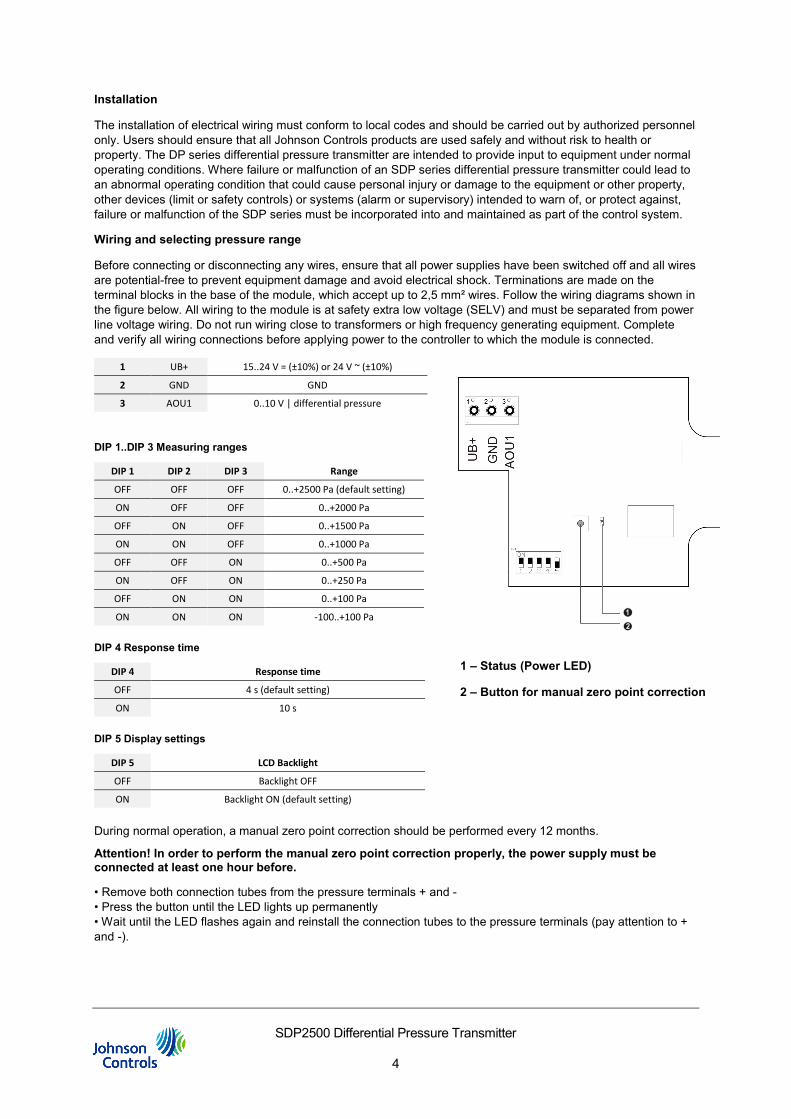
Wiring and selecting pressure range
Before connecting or disconnecting any wires, ensure that all power supplies have been switched off and all wires are potential-free to prevent equipment damage and avoid electrical shock. Terminations are made on the terminal blocks in the base of the module, which accept up to 2,5 mm² wires. Follow the wiring diagrams shown in the figure below. All wiring to the module is at safety extra low voltage (SELV) and must be separated from power line voltage wiring. Do not run wiring close to transformers or high frequency generating equipment. Complete and verify all wiring connections before applying power to the controller to which the module is connected.
1 UB+ 15..24 V = (±10%) or 24 V ~ (±10%)
2 GND GND
3 AOU1 0..10 V | differential pressure
DIP 1..DIP 3 Measuring ranges
DIP 1 DIP 2 DIP 3 Range
OFF OFF OFF 0..+2500 Pa (default setting)
ON OFF OFF 0..+2000 Pa
OFF ON OFF 0..+1500 Pa
ON ON OFF 0..+1000 Pa
OFF OFF ON 0..+500 Pa
ON OFF ON 0..+250 Pa
OFF ON ON 0..+100 Pa
ON ON ON -100..+100 Pa
DIP 4 Response time
DIP 4 Response time
OFF 4 s (default setting)
ON 10 s
DIP 5 Display settings
DIP 5 LCD Backlight
OFF Backlight OFF
ON Backlight ON (default setting)
During normal operation, a manual zero point correction should be performed every 12 months.
Attention! In order to perform the manual zero point correction properly, the power supply must be connected at least one hour before.
• Remove both connection tubes from the pressure terminals + and - • Press the button until the LED lights up permanently • Wait until the LED flashes again and reinstall the connection tubes to the pressure terminals (pay attention to + and -).
1 – Status (Power LED)
2 – Button for manual zero point correction
SDP2500 Differential Pressure Transmitter
5
AZ - Automatic Zero-Point correction (optional)
Initial Power ON: Once the device is powered up, the Auto-zero reset will be performed multiple times in intervals shorter than 10mins (contrary to the operational mode). This is to compensate the self-heating of the sensor and PCB right after start-up and to provide accurate measurements throughout operations. After ca. 30mins, the device goes fully into operational mode.
Transmitters equipped with the automatic zero-point correction are maintenance-free.
The auto-zero calibration electronically adjusts the transmitter to zero every 10 minutes. The function eliminates all output signal drifts due to thermal, electronic or mechanical effects. The auto-zero adjustment takes approx. 4 seconds after which the device returns to its normal operation. During the 4 seconds correction phase, the output and display values will freeze to the last measured value. After the zero-point correction, display values and output signal go back into live mode.
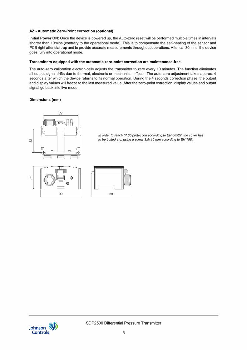
Dimensions (mm)
In order to reach IP 65 protection according to EN 60527, the cover has to be bolted e.g. using a screw 3,5x10 mm according to EN 7981.
SDP2500 Differenzdruck-Messumformer
Produkt Bulletin
Stand 05.10.2020 | Rev.1
SDP2500 Differenzdruck-Messumformer
6
EN DE
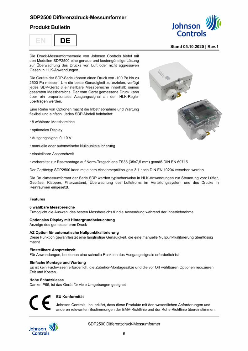
Die Druck-Messumformerserie von Johnson Controls bietet mit den Modellen SDP2500 eine genaue und kostengünstige Lösung zur Überwachung des Drucks von Luft oder nicht aggressiven Gasen in HLK-Anwendungen.
Die Geräte der SDP-Serie können einen Druck von -100 Pa bis zu 2500 Pa messen. Um die beste Genauigkeit zu erzielen, verfügt jedes SDP-Gerät 8 einstellbare Messbereiche innerhalb seines gesamten Messbereichs. Der vom Gerät gemessene Druck kann über ein proportionales Ausgangssignal an den HLK-Regler übertragen werden.
Eine Reihe von Optionen macht die Inbetriebnahme und Wartung flexibel und einfach. Jedes SDP-Modell beinhaltet:
• 8 wählbare Messbereiche
• optionales Display
• Ausgangssignal 0..10 V
• manuelle oder automatische Nullpunktkalibrierung
• einstellbare Ansprechzeit
• vorbereitet zur Rastmontage auf Norm-Tragschiene TS35 (35x7,5 mm) gemäß DIN EN 60715
Der Gerätetyp SDP2500 kann mit einem Abnahmeprüfzeugnis 3.1 nach DIN EN 10204 versehen werden.
Die Druckmessumformer der Serie SDP werden typischerweise in HLK-Anwendungen zur Steuerung von: Lüfter, Gebläse, Klappen, Filterzustand, Überwachung des Luftstroms im Verteilungssystem und des Drucks in Reinräumen eingesetzt.
Features
8 wählbare Messbereiche Ermöglicht die Auswahl des besten Messbereichs für die Anwendung während der Inbetriebnahme
Optionales Display mit Hintergrundbeleuchtung Anzeige des gemesseneren Druck
AZ Option für automatische Nullpunktkalibrierung Diese Funktion gewährleistet eine langfristige Genauigkeit, die eine manuelle Nullpunktkalibrierung überflüssig macht
Einstellbare Ansprechzeit Für Anwendungen, bei denen eine schnelle Reaktion des Ausgangssignals erforderlich ist
Einfache Montage und Wartung Es ist kein Fachwissen erforderlich, die Zubehör-Montagesätze und die vor Ort wählbaren Optionen reduzieren Zeit und Kosten.
Hohe Schutzklasse Danke IP65, ist das Gerät für viele Umgebungen geeignet
EU Konformität
Johnson Controls, Inc. erklärt, dass diese Produkte mit den wesentlichen Anforderungen und anderen relevanten Bestimmungen der EMV-Richtlinie und der Rohs-Richtlinie übereinstimmen.
SDP2500 Differenzdruck-Messumformer
7
Gehäuse mit UV- und Wetterschutz
Kunststoffgehäuse im Außenbereich können nach einiger Zeit ihre Farbe und Qualität verlieren. Daher bestehen alle Klappdeckel-Gehäuse aus speziellem weißem Polycarbonat (PC). Die lichtstabilsten Farbstoffe und Additive werden verwendet, um einen optimalen Schutz des Polymers bei gleichzeitiger Aufrechterhaltung der Farbstabilität zu erreichen. Das verwendete Titandioxid wurde speziell für Polycarbonat entwickelt und bietet durch die Reflexion des gesamten Lichtspektrums einschließlich des UV-Anteils um 340 nm einen hervorragenden UV-Schutz. Dies wirkt effektiv dem ansonsten auftretenden photochemischen Polymerabbau entgegen. Die Farben bleiben, ohne zu verblassen, lange erhalten. Das Material ist zudem kälte- und frostbeständig.
Technische Daten
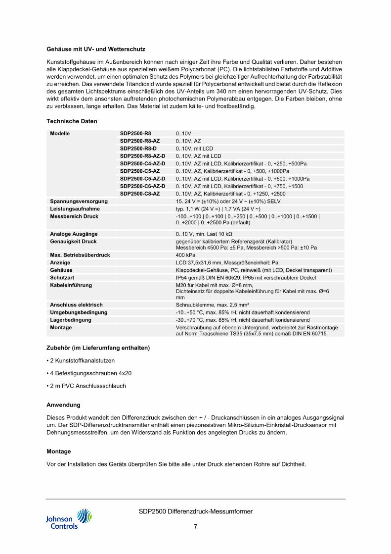
Modelle SDP2500-R8 0..10V SDP2500-R8-AZ 0..10V, AZ SDP2500-R8-D 0..10V, mit LCD SDP2500-R8-AZ-D 0..10V, AZ mit LCD SDP2500-C4-AZ-D 0..10V, AZ mit LCD, Kalibrierzertifikat - 0, +250, +500Pa SDP2500-C5-AZ 0..10V, AZ, Kalibrierzertifikat - 0, +500, +1000Pa SDP2500-C5-AZ-D 0..10V, AZ mit LCD, Kalibrierzertifikat - 0, +500, +1000Pa SDP2500-C6-AZ-D 0..10V, AZ mit LCD, Kalibrierzertifikat - 0, +750, +1500 SDP2500-C8-AZ 0..10V, AZ, Kalibrierzertifikat - 0, +1250, +2500
Spannungsversorgung 15..24 V = (±10%) oder 24 V ~ (±10%) SELV Leistungsaufnahme typ. 1,1 W (24 V =) | 1,7 VA (24 V ~) Messbereich Druck -100..+100 | 0..+100 | 0..+250 | 0..+500 | 0..+1000 | 0..+1500 |
0..+2000 | 0..+2500 Pa (default)
Analoge Ausgänge 0..10 V, min. Last 10 kΩ Genauigkeit Druck gegenüber kalibriertem Referenzgerät (Kalibrator)
Messbereich ≤500 Pa: ±5 Pa, Messbereich >500 Pa: ±10 Pa Max. Betriebsüberdruck 400 kPa Anzeige LCD 37,5x31,6 mm, Messgrößeneinheit: Pa Gehäuse Klappdeckel-Gehäuse, PC, reinweiß (mit LCD, Deckel transparent) Schutzart IP54 gemäß DIN EN 60529, IP65 mit verschraubtem Deckel Kabeleinführung M20 für Kabel mit max. Ø=8 mm,
Dichteinsatz für doppelte Kabeleinführung für Kabel mit max. Ø=6 mm
Anschluss elektrisch Schraubklemme, max. 2,5 mm² Umgebungsbedingung -10..+50 °C, max. 85% rH, nicht dauerhaft kondensierend Lagerbedingung -30..+70 °C, max. 85% rH, nicht dauerhaft kondensierend Montage Verschraubung auf ebenem Untergrund, vorbereitet zur Rastmontage
auf Norm-Tragschiene TS35 (35x7,5 mm) gemäß DIN EN 60715
Zubehör (im Lieferumfang enthalten)
• 2 Kunststoffkanalstutzen
• 4 Befestigungsschrauben 4x20
• 2 m PVC Anschlussschlauch
Anwendung
Dieses Produkt wandelt den Differenzdruck zwischen den + / - Druckanschlüssen in ein analoges Ausgangssignal um. Der SDP-Differenzdrucktransmitter enthält einen piezoresistiven Mikro-Silizium-Einkristall-Drucksensor mit Dehnungsmessstreifen, um den Widerstand als Funktion des angelegten Drucks zu ändern.
Montage
Vor der Installation des Geräts überprüfen Sie bitte alle unter Druck stehenden Rohre auf Dichtheit.
SDP2500 Differenzdruck-Messumformer
8
Bestell- Codes
Single-Pack
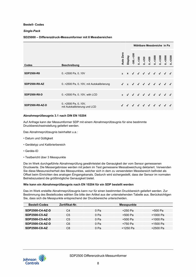
SD25000 – Differenzdruck-Messumformer mit 8 Messbereichen
Codes Beschreibung Aut
o Ze
ro
Dis
play
Wählbare Messbreiche in Pa
-100
..+10
0
0..+
100
0..+
250
0..+
500
0..+
1000
0..+
1500
0..+
2000
0..+
2500
SDP2500-R8 0..+2500 Pa, 0..10V x x ✔ ✔ ✔ ✔ ✔ ✔ ✔ ✔
SDP2500-R8-AZ 0..+2500 Pa, 0..10V, mit Autokalibrierung ✔ x ✔ ✔ ✔ ✔ ✔ ✔ ✔ ✔
SDP2500-R8-D 0..+2500 Pa, 0..10V, with LCD x ✔ ✔ ✔ ✔ ✔ ✔ ✔ ✔ ✔
SDP2500-R8-AZ-D 0..+2500 Pa, 0..10V, mit Autokalibrierung und LCD ✔ ✔ ✔ ✔ ✔ ✔ ✔ ✔ ✔ ✔
Abnahmeprüfzeugnis 3.1 nach DIN EN 10204
Auf Anfrage kann der Messumformer SDP mit einem Abnahmeprüfzeugnis für eine bestimmte Druckbereichseinstellung geliefert werden.
Das Abnahmeprüfzeugnis beinhaltet u.a.:
• Datum und Gültigkeit
• Gerätetyp und Kalibrierbereich
• Geräte-ID
• Testbericht über 3 Messpunkte
Die im Werk durchgeführte Abnahmeprüfung gewährleistet die Genauigkeit der vom Sensor gemessenen Druckwerte. Die Messergebnisse werden mit jedem im Test gemessene Messabweichung deklariert. Verwenden Sie diese Messunsicherheit des Messpunktes, welcher sich in dem zu verwendeten Messbereich befindet als Offset beim Einrichten des analogen Eingangskanals. Dadurch wird sichergestellt, dass der Sensor im normalen Betriebszustand die größtmögliche Genauigkeit bietet.
Wie kann ein Abnahmeprüfzeugnis nach EN 10204 für ein SDP bestellt werden
Das im Werk erstellte Abnahmeprüfzeugnis kann nur für einen bestimmten Druckbereich geliefert werden. Zur Bestimmung des Bestellcodes wählen Sie bitte den Artikel aus der untenstehenden Tabelle aus. Berücksichtigen Sie, dass sich die Messpunkte entsprechend der Druckbereiche unterscheiden.
Bestell-Codes Zertifikat-Nr. Messpunkte
SDP2500-C4-AZ-D C4 0 Pa +250 Pa +500 Pa SDP2500-C5-AZ C5 0 Pa +500 Pa +1000 Pa SDP2500-C5-AZ-D C5 0 Pa +500 Pa +1000 Pa SDP2500-C6-AZ-D C6 0 Pa +750 Pa +1500 Pa SDP2500-C8-AZ C8 0 Pa +1250 Pa +2500 Pa
SDP2500 Differenzdruck-Messumformer
9
Installation
Die Installation der elektrischen Leitungen muss den örtlichen Vorschriften entsprechen und sollte nur von autorisiertem Personal durchgeführt werden. Benutzer sollten sicherstellen, dass alle Produkte von Johnson Controls sicher und ohne Gefahr für Gesundheit und Eigentum verwendet werden. Die Differenzdruck-Messumformer der Serie SDP sind dafür vorgesehen, unter normalen Betriebsbedingungen Messsignale an Steuersysteme zu liefern. Bei Ausfall oder einer Fehlfunktion eines Differenzdrucktransmitters der Serie SDP, welcher zu Personenschäden oder Schäden an der Anlage oder anderem Eigentum führen könnte, müssen Vorrichtungen (Begrenzungs- oder Sicherheitssteuerungen) oder Systeme (Alarm- oder Überwachungssysteme), die vor einem Ausfall oder einer Fehlfunktion der Serie SDP warnt bzw. schützt, in das Steuersystem integriert und als Teil davon gewartet werden.
Anschluss und DIP-Einstellung
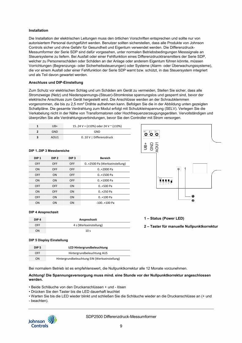
Zum Schutz vor elektrischen Schlag und um Schäden am Gerät zu vermeiden, Stellen Sie sicher, dass alle Stromzweige (Netz) und Niederspannungs-(Steuer)-Stromkreise spannungslos und gesperrt sind, bevor der elektrische Anschluss zum Gerät hergestellt wird. Die Anschlüsse werden an der Schraubklemmen vorgenommen, die bis zu 2,5 mm² Drähte aufnehmen kann. Befolgen Sie die in der Abbildung unten gezeigten Schaltpläne. Die gesamte Verdrahtung zum Modul erfolgt mit Schutzkleinspannung (SELV). Verlegen Sie die Verkabelung nicht in der Nähe von Transformatoren oder Hochfrequenzerzeugungsgeräten. Vervollständigen und überprüfen Sie alle Verdrahtungsverbindungen, bevor Sie den Controller mit Strom versorgen.
1 UB+ 15..24 V = (±10%) oder 24 V ~ (±10%)
2 GND GND
3 AOU1 0..10 V | Differenzdruck
DIP 1..DIP 3 Messbereiche
DIP 1 DIP 2 DIP 3 Bereich
OFF OFF OFF 0..+2500 Pa (Werkseinstellung)
ON OFF OFF 0..+2000 Pa
OFF ON OFF 0..+1500 Pa
ON ON OFF 0..+1000 Pa
OFF OFF ON 0..+500 Pa
ON OFF ON 0..+250 Pa
OFF ON ON 0..+100 Pa
ON ON ON -100..+100 Pa
DIP 4 Ansprechzeit
DIP 4 Ansprechzeit
OFF 4 s (Werkseinstellung)
ON 10 s
DIP 5 Display Einstellung
DIP 5 LCD Hintergrundbeleuchtung
OFF Hintergrundbeleuchtung AUS
ON Hintergrundbeleuchtung EIN (Werkseinstellung)
Bei normalem Betrieb ist es empfehlenswert, die Nullpunktkorrektur alle 12 Monate vorzunehmen.
Achtung! Die Spannungsversorgung muss mind. eine Stunde vor der Nullpunktkorrektur angeschlossen werden.
• Beide Schläuche von den Druckanschlüssen + und - lösen • Drücken Sie den Taster bis die LED dauerhaft leuchtet • Warten Sie bis die LED wieder blinkt und schließen Sie die Schläuche wieder an die Druckanschlüsse an (+ und - beachten).
1 – Status (Power LED)
2 – Taster für manuelle Nullpunktkorrektur
SDP2500 Differenzdruck-Messumformer
10
AZ – Automatische Nullpunktkorrektur (optional)
Erstmaliges Einschalten: Sobald das Gerät eingeschaltet ist, wird die automatische Nullstellung mehrmals in Intervallen von weniger als 10 Minuten durchgeführt (im Gegensatz zum Betriebsmodus). Dies dient dazu, die Eigenerwärmung des Sensors und der Leiterplatte nach dem Einschalten zu kompensieren und durchgehend genaue Messungen zu ermöglichen. Nach etwa 30 Minuten geht das Gerät vollständig in den Betriebsmodus über.
Messumformer mit automatischer Nullpunktkorrektur sind wartungsfrei.
Die automatische Nullpunktkorrektur stellt den Sendernullpunkt alle 10 Minuten elektronisch ein. Die Funktion eliminiert jegliche Ausgangssignaldrifts aufgrund von thermischen, elektronischen oder mechanischen Effekten. Der Auto-Nullabgleich dauert ca. 4 Sekunden. Danach kehrt das Gerät in den normalen Messmodus zurück. Während des 4-Sekunden-Abgleichs frieren die Ausgangs- und Anzeigewerte auf den neuesten Messwert ein.
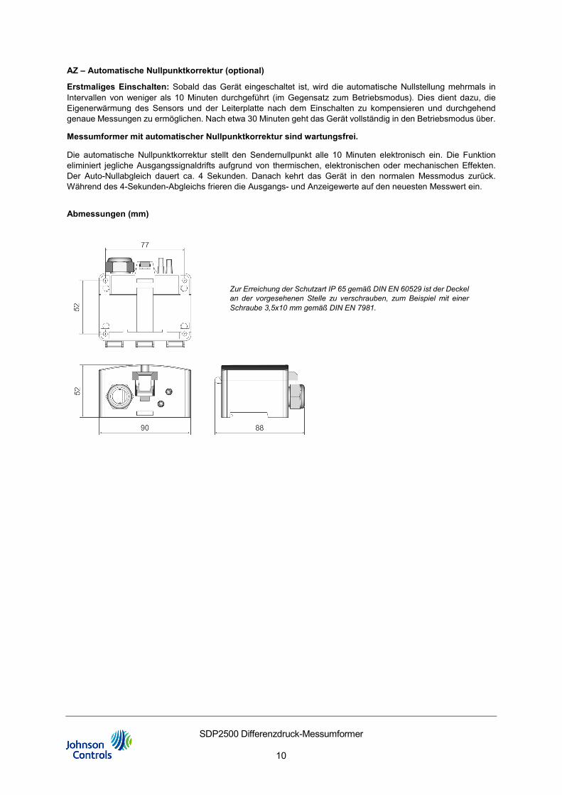
Abmessungen (mm)
Zur Erreichung der Schutzart IP 65 gemäß DIN EN 60529 ist der Deckel an der vorgesehenen Stelle zu verschrauben, zum Beispiel mit einer Schraube 3,5x10 mm gemäß DIN EN 7981.
SDP2500 Differenzdruck-Messumformer
11
European Single Point of Contact:
JOHNSON CONTROLS WESTENDHOF 3
45143 ESSEN GERMANY
www.johnsoncontrols.com
www.johnsoncontrols.com/locations
Metasys® and Johnson Controls® are registered trademarks of Johnson Controls. All other marks herein are the marks of their respective owners. © 2020 Johnson Controls.