sds1230-21-31-00
DESCRIPTION
AMM PART 1CHAPTER 21TRANSCRIPT

PRESSURIZATION CONTROL SYSTEM
AIRCRAFTMAINTENANCE MANUAL
EFFECTIVITY: 21-31-00 Page 1
May 04/99
wip
sds1
230

PRESSURIZATION CONTROL SYSTEM
INTRODUCTION
The Cabin Pressure Control System (CPCS) controls cabin altitude,cabin rate of change and cabin differential pressure during all flightphases.
DESCRIPTION
The CPCS has two modes of operation: automatic and manual mode.The automatic mode is the primary mode. The manual mode is usedin case of failure of the automatic mode. The pressurization controlsystem has these components:
− Digital controller.
− Manual controller.
− Electropneumatic outflow valve.
− Pneumatic outflow valve.
− Pressure regulator valve.
− Check valve.
− Ejector pump.
− Static port.
− Air filter.
− Vacuum line.
− Reference pressure line.
The figure ″PRESSURIZATION CONTROL SYSTEM - MAINCOMPONENT LOCATIONS″ shows the location of the maincomponents of the system.
AIRCRAFTMAINTENANCE MANUAL
EFFECTIVITY: ALL 21-31-00Page 2
Sep 29/99
wip
sds1
230

DET. B
DET. D
AZONE
191
B
ZONES275276
DET. A
CD
ZONES223224
DIGITALCONTROLLER
MANUALCONTROLLER
PRESSURE LINE
VACUUM LINE
DET. C
PNEUMATICOUTFLOW VALVE
ELECTROPNEUMATICOUTFLOW VALVE
REFERENCE PRESSURE TUBE
VACUUM TUBE
STATICPORT
PRESSUREREGULATOR VALVE
PRESSUREREGULATOR VALVE
TUBE
VACUUM PUMP OUTLET
E
DET.E(LH SIDE)
CHECKVALVE
145AMM210188.MCE E
PRESSURIZATION CONTROL SYSTEM - MAIN COMPONENT LOCATIONS
AIRCRAFTMAINTENANCE MANUAL
EFFECTIVITY: ALL 21-31-00 Page 3
Mar 29/01
wip
sds1
230

COMPONENTS
DIGITAL CONTROLLER
The digital controller is the unit which controls the cabin pressure rateof change. It has two basic assemblies, as follows:
− Mechanical sub-assembly.
− Electronic sub-assembly.
The digital controller does these functions:
− Keep the cabin rate of change as low as possible as the aircraftflight level changes.
− Automatic pre-pressurization sequence on the ground to preventcabin ″bump″ during takeoff.
− Takeoff without pressurization.
− Automatic depressurization sequence after landing to prevent cabin″bump″ during landing.
− Selection of the climbing rate to ″MIN″, to keep the pressurizationrate of change to a limit.
− Automatic in flight failure detection and automatic power up test.
− Selection of MAN mode.
The digital controller receives three parameters from the Air DataComputers (ADC 1 and ADC 2).
− Aircraft altitude (ZA).
− Aircraft rate of change (VZA).
− Barometric corrections (BARO).
The figure ″PRESSURIZATION CONTROL SYSTEM - DIGITALCONTROLLER″, and ″DIGITAL CONTROLLER″ table shows thecontrols and indications of the digital controller front panel.
DIGITAL CONTROLLER TABLE
REF.CONTROL/INDICATOR
POSITION/INDICATION
FUNCTION
1 DUMP Switch
Released
Turns off the fast depressurization mode.
The DUMP indicator in the switch stays
off.
Pushed
Select the fast depressurization mode.
The DUMP indicator in the switch turns
on.
2LAND ELEV
Display-
Shows the selected landing field eleva-
tion and fault indications.
3ELV SET
Switch-
Increases or decreases the landing field
elevation in the display. The increments
are of 100 ft at a speed of 200 ft/min.
The speed increases to 1,000 ft/min
after 5 seconds.
4AUTO/MAN
Switch
Released
Selects the automatic mode of operation.
The MAN indicator in the switch stays
off.
Pushed
Selects the manual mode of operation.
The MAN indicator in the switch turns
on.
AIRCRAFTMAINTENANCE MANUAL
EFFECTIVITY: ALL 21-31-00Page 4
Apr 28/06
wip
sds1
230

AUTO PRESSLAND ELEV (ft) ELV SET
+
-
DUMP AUTO/MAN
ON MAN
A
DET. A
1
2
3
4
145AMM210093.MCE C
PRESSURIZATION CONTROL SYSTEM - DIGITAL CONTROLLER
AIRCRAFTMAINTENANCE MANUAL
EFFECTIVITY: ALL 21-31-00 Page 5
Mar 29/01
wip
sds1
230

MANUAL CONTROLLER
The manual controller is installed in the cockpit center console. In themanual mode, the manual controller operates the Pneumatic OutflowValve (POV) through its control knob. The control knob permits thecrew to set any cabin altitude rate of change between −1,500 and2,500 ft/min.
To get the necessary cabin altitude rate of change the crew must turnthe knob. The control knob turns a needle in the manual controller,which operates as follows:
− Turning the knob clockwise will connect the reference pressure lineto suction. This will make the cabin climb by opening the POV.
− Turning the knob counterclockwise will connect the reference pres-sure line to cabin pressure. This will make the cabin descend byclosing the POV.
NOTE: The reference pressure line has a capillary to cause apressure drop in the line to the pneumatic relay of thePOV.
The figure ″PRESSURIZATION CONTROL SYSTEM - MANUALCONTROLLER″ shows the unit.
AIRCRAFTMAINTENANCE MANUAL
EFFECTIVITY: ALL 21-31-00Page 6
May 04/99
sds1
230

DNU
P
DET. A
DET. B
A
B
VIEW FROM PLATE
GREEN MARK(DN POSITION)VZ: -1500 ft/minAPPROX.
UP POSITIONVZ: +1500 ft/minAPPROX.
UP EXTREME POSITIONVZ: +2500 ft/minAPPROX.
WHITE MARK"LEVEL FLIGHT" ZONEVZ: 0
REGULATOR SHOWN IN"CABIN DESCENT" POSITION.VZ BETWEEN 0 AND -1500 ft/min
AUTO PRESSLAND ELEV (ft) ELV SET
+
-
DN
UPDUMP AUTO/MAN
ON MAN
145AMM210158.MCE A
PRESSURIZATION CONTROL SYSTEM - MANUAL CONTROLLER
AIRCRAFTMAINTENANCE MANUAL
EFFECTIVITY: ALL 21-31-00 Page 7
Sep 29/99
wip
sds1
230

ELECTROPNEUMATIC OUTFLOW VALVE (EOV)
The Electropneumatic Outflow Valve (EOV) is installed in the rearpressure bulkhead through a flange/clamp connection. The body ofthe EOV is made of composite material.
In the automatic mode, the digital controller operates the EOV throughthe voltage supplied to the torque motor. In this mode, the EOVcontrols the Pneumatic Outflow Valve (POV) through the interconnect-ing tube. In the manual mode, the EOV stays closed.
The torque motor of the EOV has two nozzles: one is connected tothe cabin pressure reference line and the other to the suction line.The position of the torque motor quadrant (as a function of torquemotor input voltage) will open or close the nozzles.
The two nozzles connect to the servo-chamber of the EOV. At thelower part of the EOV, there is a compensation chamber connected tocabin pressure. When the pressure in the servo-chamber is the sameas the pressure in the compensation chamber, the EOV stays closed.This is a function of the spring in the servo-chamber.
The EOV has three safety devices, as follows:
− Overpressure relief valve.
− Negative pressure relief valve.
− Cabin altitude limiter.
The overpressure relief valve and the negative pressure relief valveare part of the same assembly. This assembly also has the connec-tion for the interconnecting tube, which connects the EOV to the POV.The overpressure relief valve has a manometric capsule which feelsthe cabin differential pressure. The inner part of the capsule feels thecabin pressure. The outer part of the capsule feels static pressurethrough the static port. When there is an overpressure, the expandedcapsule opens its valve. This will cause the EOV to open by decreas-ing its servo-chamber pressure.
When the outer static pressure is more than cabin pressure, it pushes
the EOV deflector. This causes the negative pressure relief valve toopen, decreasing the servo-chamber pressure and opening the valve.
The cabin altitude limiter has an aneroid capsule which feels cabinpressure. When cabin altitude is 14,000 ± 500 ft, the expandedcapsule opens its valve. This will close the EOV and keep the cabinaltitude to the limits.
PNEUMATIC OUTFLOW VALVE (POV)
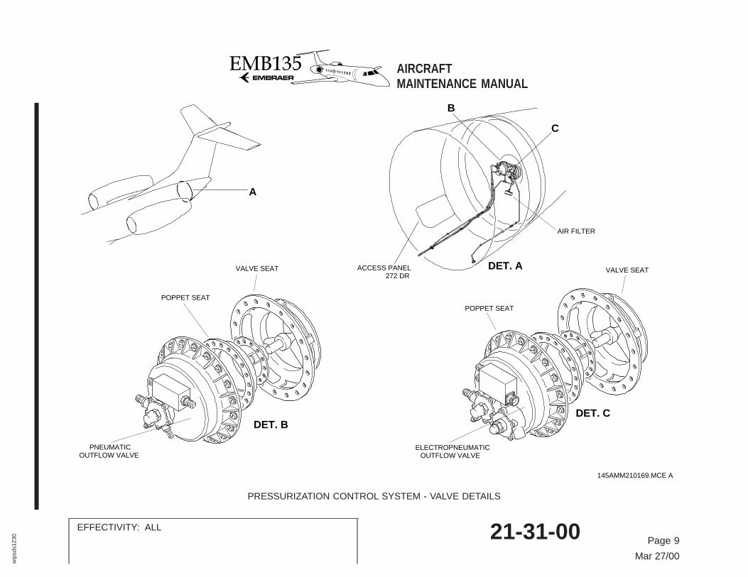
The Pneumatic Outflow Valve (POV) is installed on the rear pressurebulkhead, through a flange/clamp connection. The body of the POV ismade of composite material.
The POV controls the cabin airflow outlet through the manual regula-tor when the system operates in manual mode. In the automaticmode, the EOV controls the POV through the interconnecting tube.
The POV has two safety devices: an overpressure relief valve and anegative pressure relief valve. These devices operate the same asthose in the EOV.
The figure ″PRESSURIZATION CONTROL SYSTEM - VALVEDETAILS″ shows the interior of the pneumatic and electropneumaticoutflow valves.
AIRCRAFTMAINTENANCE MANUAL
EFFECTIVITY: ALL 21-31-00Page 8
Sep 27/00
wip
sds1
230
DET. AACCESS PANEL272 DR
DET. CDET. B
C
B
POPPET SEAT
VALVE SEAT
ELECTROPNEUMATICOUTFLOW VALVE
POPPET SEAT
VALVE SEAT
PNEUMATICOUTFLOW VALVE
A
AIR FILTER
145AMM210169.MCE A
PRESSURIZATION CONTROL SYSTEM - VALVE DETAILS
AIRCRAFTMAINTENANCE MANUAL
EFFECTIVITY: ALL 21-31-00 Page 9
Mar 27/00
wip
sds1
230

PRESSURE REGULATOR VALVE
The pressure regulator valve adjusts bleed air pressure from thepneumatic system (Ref. 36-00) to 20 ± 1 psig to supply the ejectorpump. This valve is installed forward of the wing-to-fuselage attach-ment. There is one valve on each side of the forward part of thewing-to-fuselage fairing.
CHECK VALVE
The check valve permits ejector pump operation in case one bleed airduct fails or no bleed air is supplied to one main bleed duct. Thisvalve is installed forward of the wing-to-fuselage attachment. There isone valve on each side of the forward part of the wing-to-fuselagefairing.
EJECTOR PUMP
The ejector pump makes suction using bleed air pressure through anair ejector. The pump receives an adjusted pressure of 20 psig at itsinlet.
This permits the pump to supply −3 psig on the suction line. Thebleed air flows overboard at the pump outlet.
The ejector pump is installed at the forward part of the wing-to-fuselage fairing.
The figure ″PRESSURIZATION CONTROL SYSTEM - PRESSUREREGULATOR, CHECK VALVE AND EJECTOR PUMP″ shows thelocation of the units.
AIRCRAFTMAINTENANCEMANUAL
EFFECTIVITY: ALL 21-31-00Page 10
Sep 29/99
wip
sds1
230

ZONE191
VACUUM LINE
EJECTORPUMP
PRESSUREREGULATOR
VALVE
PRESSUREREGULATOR
VALVE
PRESSUREREGULATOR
VALVE
REGULATEDPRESSURE(20 PSID)
EJECTOR PUMP
SUCTION(-3.0 PSIG)
DISCHARGEPORT
DET. A
DET. B
A
BB
C
DET. C
DET.D(LH SIDE)
CHECKVALVE
D
145AMM210162.MCE C
PRESSURIZATION CONTROL SYSTEM - PRESSURE REGULATOR, CHECK VALVE AND EJECTOR PUMP
AIRCRAFTMAINTENANCE MANUAL
EFFECTIVITY: ALL 21-31-00 Page 11
Mar 29/01
wip
sds1
230

STATIC PORT
The static port feels the ambient static pressure through the sensingorifices. The static port transmits this signal to the related outflowvalve through a tube. This permits the overpressure relief valve tooperate.
The static port is electrically heated to prevent blockage of the sens-ing orifices because of freezing.
The static ports are installed at the lower part of rear fuselage I, nearthe cargo door.
AIR FILTER
The cabin air filter prevents nicotine and dust from going into theoutflow valves. This increases their life and reliability. The filter has afolded paper in a rubber housing with a threaded end.
The cabin air flows through the filtering element and goes to the EOVthrough the tubing at the threaded end. The air filter is installed nearthe EOV.
The figure ″PRESSURIZATION CONTROL SYSTEM - COMPONENTDETAILS″ shows the installation of some components of the system.
AIRCRAFTMAINTENANCE MANUAL
EFFECTIVITY: ALL 21-31-00Page 12
May 04/99
sds1
230

A
ELECTROPNEUMATICOUTFLOW VALVE
PNEUMATICOUTFLOW
VALVE
PRESSURIZATIONSTATIC PORT
PRESSURIZATIONSTATIC PORT
AIR FILTER
SEALANT
PRESSURIZATIONSTATIC PORT
SENSINGORIFICES
DET. A
145AMM210163.MCE A
PRESSURIZATION CONTROL SYSTEM - COMPONENT DETAILS
AIRCRAFTMAINTENANCE MANUAL
EFFECTIVITY: ALL 21-31-00 Page 13
May 04/99
sds1
230

OPERATION
The pressurization control system adjusts the cabin pressure bycontrolling the exhaust rate of the cabin air from the EnvironmentalControl System (ECS). The system can operate in two modes:
− Automatic mode.
− Manual mode.
AUTOMATIC MODE
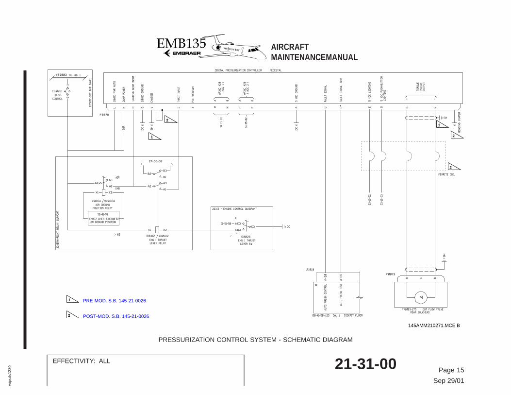
In the automatic mode, the Digital Controller (DC) operates the twooutflow valves (EOV and POV). The DC sends current signals to thetorque motor of the EOV to operate the two valves.
When DC Bus 1 is energized, it supplies the DC through the PRESSCONTROL circuit breaker. If the AUTO/MAN switch is released, theDC will start sending signals to the torque motor of the EOV tooperate the two outflow valves. The DC will then control the cabinaltitude (ZC) and the cabin rate of change (VZC). To do this functionthe DC receives these parameters:
− Cabin pressure, through its own pressure sensor.
− Aircraft altitude and baro correction, through signals from ADC 1and 2.
The DC program causes the measured cabin altitude (ZC) to be thesame or tending to a scheduled cabin altitude (ZCOT). For the ZCOT,the DC gives the correcting cabin altitude (ZCO). The ZCO is thevalue at which the system must adjust the ZC. The ZCO follows theZCOT up the cabin rate limit of change (VZLIM).
The DC will then supply the torque motor voltage to get the correctopening of the EOV. This will cancel the error between the measuredcabin altitude (ZC) and the calculated correcting altitude (ZCO). ThePOV will follow the movements of the EOV.
NOTE: The scheduled cabin altitude (ZCOT) can have differentvalues for different flight sequences, as follows:
– Automatic pre-pressurization sequence on the ground.
– Takeoff sequence (abort capability).
– Flight sequences (climb or descent).
– Automatic rate of descent increase sequence.
– Automatic depressurization on the ground.
The figure ″PRESSURIZATION CONTROL SYSTEM - SCHEMATICDIAGRAM″ shows the electrical interfaces of the system.
AIRCRAFTMAINTENANCE MANUAL
EFFECTIVITY: ALL 21-31-00Page 14
Mar 29/01
wip
sds1
230
CB0031
5
2
1
M
DC BUS 1
XK0264
A1
A3A2
X2
X1
K0264
AIR
GND
S0025
C3 NC3
NO3
50R
DC
WT0003
ENG 1 THRUST
LEVER SW
P0079
A
B
OUT FLOW VALVEREAR BULKHEAD
ENRGZ WHEN AIRCRAFTON GROUND POSITION
XK0412
A1
A3A2
B1
B3B2
X1
X2
K0412
AIR GROUNDPOSITION RELAY
ENG 1 THRUSTLEVER RELAY
DAU 1
225DTC-CKT BKR PANEL
J1019
A-30
A-65
P0078
L
K
H
G
V
T
J
A
U
C#
N
P
R
B
C
DC
28VDC PWR AUTO
DUMP POWER
LANDING GEAR INPUT
28VDC GROUND
CHASSIS
PIN PROGRAM
THROT INPUT
5 VDC GROUND
FAULT SIGNAL
FAULT SIGNAL INHB
A B
ARINC 429
( ADC 1 )
A B
ARINC 429
( ADC 2 )
+ -
TORQUE
MOTOR
OUTPUT
AUTO PRESN CONTROL
AUTO PRESN TEST
COCKPIT FLOOR
DC
J1
SH
C
224ERW-RIGHT RELAY SUPPORT
DIGITAL PRESSURIZATION CONTROLLER PEDESTAL
< 65
> 65
M
223IZ - ENGINE CONTROL QUADRANT
FV0003-275
SH
(30-41-50)-123
31-51-50
34-15-81
34-15-82
SH
PRESS
CONTROL
32-61-50
27-53-52
E
D
5 VDC LIGHTING
33-12-52
33-12-53
5 VDC PUSH-BUTTON
LIGHTING
FERRITE COIL
BONDING JUMPER
1
2
2
2
1
1
2
PRE-MOD. S.B. 145-21-0026
POST-MOD. S.B. 145-21-0026
145AMM210271.MCE B
PRESSURIZATION CONTROL SYSTEM - SCHEMATIC DIAGRAM
AIRCRAFTMAINTENANCEMANUAL
EFFECTIVITY: ALL 21-31-00 Page 15
Sep 29/01
wip
sds1
230

AUTOMATIC PRE-PRESSURIZATION SEQUENCE ON THE
GROUND
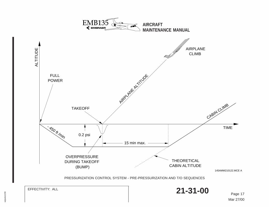
When the aircraft is on the ground and the Thrust Lever Angle (TLA)is more than 65o, the pre-pressurization sequence starts. Thissequence prevents cabin ″bumps″ because of irregular airflow on thefuselage during rotation and takeoff. It also makes it unnecessary tocontrol cabin altitude immediately after rotation, as the cabin altitudefollows the aircraft altitude.
During this sequence the scheduled cabin altitude (ZCOT) is suchthat its scheduled cabin pressure (PCOT) is PCM + 15 mbar (to thescheduled altitude, ambient measured pressure at the ″full power″setting plus 15 mbar). The limit of cabin rate of change will be −450ft/min.
NOTE: For takeoff without air conditioning supply, this sequencecauses the outflow valves to close.
TAKEOFF SEQUENCE
As soon as the air/ground signal changes to flight condition, thetakeoff sequence starts.
This sequence prevents the re-selection of landing altitude if anaborted flight and emergency return to the takeoff field is necessary.
During this sequence, the scheduled cabin altitude (ZCOT) stays thesame as the ZCOT of the pre-pressurization sequence for 15 minutes.Or until the ZCOT is more than the theoretical cabin altitude, if itoccurs first.
NOTE: Theoretical law.
The theoretical cabin altitude is related to the aircraft altitude (ZA) andthe maximum climb performance of the aircraft (ZA = ZA.t). It is alsorelated to the maximum nominal differential pressure (7.8 psi) for acabin altitude of 8,000 ft at an aircraft altitude of 37,000 ft.
The function of the theoretical cabin altitude law is to have themaximum differential pressure at the lowest possible aircraft altitudewith a minimum rate of climb limit (maximum rate of cabin climb is600 ft/min for aircraft with CPCS digital controller of the P/N22250Nxxxxxx series and 700 ft/min for aircraft with CPCS digitalcontroller of the P/N 92185A010100).
The ″THEORETICAL LAW″ table gives the ZCTH.
THEORETICAL LAW TABLE
ZA ZCTH
0 to 5,000 ft 0.185359 * ZA - 1,500
5,000 to 10,000 ft 0.181550 * ZA - 1,481
10,000 to 15,000 ft 0.192977 * ZA - 1,595.2
15,000 to 19,000 ft 0.222177 * ZA - 2,033.2
19,000 to 24,000 ft 0.255186 * ZA - 2,660.4
24,000 to 29,000 ft 0.313587 * ZA - 4,062
29,000 to 33,970 ft 0.365719 * ZA - 5,573.9
above 33,970 ft 0.379658 * ZA - 6,047.3
The figure ″PRESSURIZATION CONTROL SYSTEM - PRE-PRESSURIZATION AND T/O SEQUENCES″ shows the graphicrelated to these sequences.
AIRCRAFTMAINTENANCE MANUAL
EFFECTIVITY: ALL 21-31-00Page 16
Apr 28/06
wip
sds1
230
FULLPOWER
TAKEOFF
AIRPLA
NE ALT
ITUDE
AIRPLANECLIMB
CABIN CLIMB
TIME
ALT
ITU
DE
0.2 psi
THEORETICALCABIN ALTITUDE
OVERPRESSUREDURING TAKEOFF
(BUMP)
15 min max.
145AMM210122.MCE A
- 450 ft /min
PRESSURIZATION CONTROL SYSTEM - PRE-PRESSURIZATION AND T/O SEQUENCES
AIRCRAFTMAINTENANCE MANUAL
EFFECTIVITY: ALL 21-31-00 Page 17
Mar 27/00
wip
sds1
230
FLIGHT SEQUENCE
When the landing gear switch is in flight condition (but not during thetakeoff sequence) the flight sequence starts. During this sequencethe scheduled cabin altitude (ZCOT) is the higher value betweenZCTH and ZATT (landing altitude minus 300 ft, with barometric cor-rection from the ADC).
The cabin altitude rate of change limit (VZLIM) during this sequenceis:
− VZLIMCClimb = 600 ft/min for aircraft with CPCS digital controller of theP/N 22250Nxxxxxx series and 700 ft/min for aircraft with CPCSdigital controller of the P/N 92185A010100.
− VZLIMDDescent = −450 ft/min.
AUTOMATIC RATE OF DESCENT INCREASE SEQUENCE
When the aircraft rate of descent is more than −200 ft/min, thissequence starts. The function of this sequence is to calibrate thecabin rate of descent in relation to the aircraft descent profile.
In case of aircraft rapid descent, this sequence will increase the rateof descent limit (VZLIMD) in relation to the Remaining Flight Time(RFT). The RFT is calculated as follows:
− RFT = (ZA − (ZATT + 300))/VZA
The limit of VZLIMD is −500 ft/min.
AUTOMATIC DEPRESSURIZATION SEQUENCE ON THE GROUND
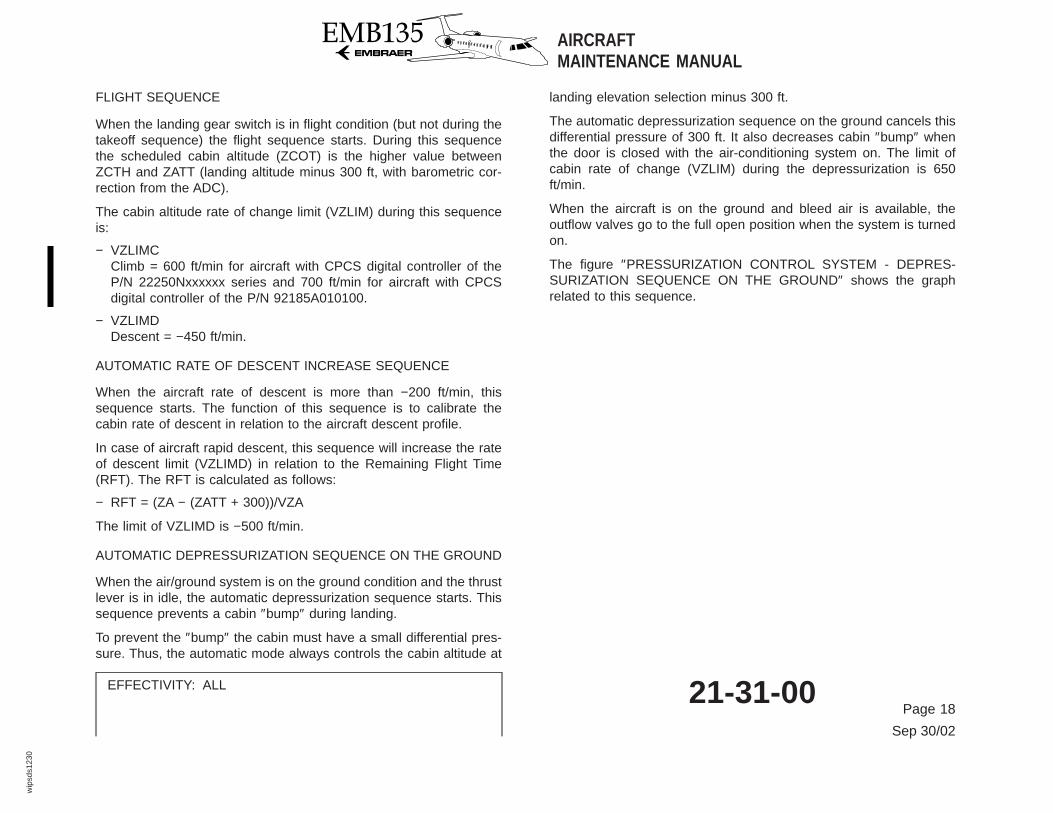
When the air/ground system is on the ground condition and the thrustlever is in idle, the automatic depressurization sequence starts. Thissequence prevents a cabin ″bump″ during landing.
To prevent the ″bump″ the cabin must have a small differential pres-sure. Thus, the automatic mode always controls the cabin altitude at
landing elevation selection minus 300 ft.
The automatic depressurization sequence on the ground cancels thisdifferential pressure of 300 ft. It also decreases cabin ″bump″ whenthe door is closed with the air-conditioning system on. The limit ofcabin rate of change (VZLIM) during the depressurization is 650ft/min.
When the aircraft is on the ground and bleed air is available, theoutflow valves go to the full open position when the system is turnedon.
The figure ″PRESSURIZATION CONTROL SYSTEM - DEPRES-SURIZATION SEQUENCE ON THE GROUND″ shows the graphrelated to this sequence.
AIRCRAFTMAINTENANCE MANUAL
EFFECTIVITY: ALL 21-31-00Page 18
Sep 30/02
wip
sds1
230

AIRPLANEDESCENT
AIR
PLA
NE
ALTITU
DE
AIRPLANE TOUCHDOWN
IDLE POSITION
CABIN ALTITUDE
OVERPRESSUREDURING LANDING
(BUMP)
-300 ft
+650 ft/min
OUTFLOW VALVESFULLY OPEN
p
AIR CONDITIONING OFFOR
MAIN DOOR OPEN
TIME
ALT
ITU
DE
AND THRUST LEVER AT
145AMM210121.MCE A
PRESSURIZATION CONTROL SYSTEM - DEPRESSURIZATION SEQUENCE ON THE GROUND
AIRCRAFTMAINTENANCE MANUAL
EFFECTIVITY: ALL 21-31-00 Page 19
Mar 27/00
wip
sds1
230
MANUAL MODE
The manual mode pneumatically controls the cabin pressure. Theposition of the manual controller sets a reference pressure whichcontrols the opening of the Pneumatic Outflow Valve (POV).
The crew must turn the manual controller knob to get the necessarycabin rate of change. While turning the knob, the crew must follow theparameters on the EICAS display (Ref. 21-32).
During the manual mode, the digital controller is deenergized, and theEOV stays closed. The AUTO/MAN switch stays pressed and theMAN indicator in the switch stays on.
FAST CABIN DEPRESSURIZATION
When the NORM/DUMP switch, on the digital controller, is set toDUMP:
− It cuts the electrical connection between the digital controller andthe Electropneumatic Outflow Valve (EOV).
− It applies 10 V DC across the torque motor terminals. The torquemotor quadrant closes the cabin pressure port and opens thesuction port. The servo-chamber pressure decreases and the EOVopens.
− The DUMP indicator in the switch stays on.
NOTE: In flight, the cabin altitude limiter in the EOV will keep thecabin altitude to the limit of 14,000 ± 500 ft.
When the system is in the manual mode, turning the manual control-ler fully clockwise will also set a fast depressurization. The pneumaticoutflow valve will open and the cabin rate of climb limit will be of 2,500ft/min.
The figure ″PRESSURIZATION CONTROL SYSTEM - PRESSURIZA-TION DIAGRAM″ shows the operation of the system.
AIRCRAFTMAINTENANCEMANUAL
EFFECTIVITY: ALL 21-31-00Page 20
May 04/99
sds1
230

AUTO PRESS
LAND ELEV (ft)ELV SET
+
-
DUMP AUTO/MAN
ON MAN
1
2
3
OVERPRESSURE RELIEF VALVE
NEGATIVE PRESSURE RELIEF VALVE
CABIN ALTITUDE LIMITER
PRESSURIZED AREA
REAR PRESSURE BULKHEAD
NON-PRESSURIZED AREA
THRUST LEVER
AIR/GROUND
ADC 1
ADC 2
DC BUS 136-10-00 36-10-00
1
2
31
2
145AMM210129.MCE A
PRESSURIZATION CONTROL SYSTEM - PRESSURIZATION DIAGRAM
AIRCRAFTMAINTENANCE MANUAL
EFFECTIVITY: ALL 21-31-00 Page 21
Mar 29/01
wip
sds1
230

THIS PAGE INTENTIONALLY LEFT BLANK
AIRCRAFTMAINTENANCE MANUAL
EFFECTIVITY: ALL
21-31-00Page 22
May 04/99