se-01 heat tracing components & solutions 01 heat... · sst group production facilities are...
TRANSCRIPT

HEAT TRACING COMPONENTS &
SOLUTIONS
CATALOGUE


HEAT TRACING COMPONENTS &
SOLUTIONS
CATALOGUE

Introduction
2
About SST Group . . . . . . . . . . . . . . . . . . . . . . . . . . . . . . . . . . . . . . . . . . . . . . . . . . . . . . . . . . . . . . . . . . . 4Our Products . . . . . . . . . . . . . . . . . . . . . . . . . . . . . . . . . . . . . . . . . . . . . . . . . . . . . . . . . . . . . . . . . . . . . . . . 5Turnkey Heat Tracing Solutions . . . . . . . . . . . . . . . . . . . . . . . . . . . . . . . . . . . . . . . . . . . . . . . . . . . . . . . 6Our Capabilities . . . . . . . . . . . . . . . . . . . . . . . . . . . . . . . . . . . . . . . . . . . . . . . . . . . . . . . . . . . . . . . . . . . . . . 7Quality Assurance . . . . . . . . . . . . . . . . . . . . . . . . . . . . . . . . . . . . . . . . . . . . . . . . . . . . . . . . . . . . . . . . . . . 8
1. ECO Line Self-Regulating Heating Cables Self-Regulating Heating Cable LTM . . . . . . . . . . . . . . . . . . . . . . . . . . . . . . . . . . . . . . . . . . . . . . . . . . . . . . . . . . . . . . . . . . . 10Self-Regulating Heating Cable LTL . . . . . . . . . . . . . . . . . . . . . . . . . . . . . . . . . . . . . . . . . . . . . . . . . . . . . . . . . . . . . . . . . . . . 12Self-Regulating Heating Cable LTR . . . . . . . . . . . . . . . . . . . . . . . . . . . . . . . . . . . . . . . . . . . . . . . . . . . . . . . . . . . . . . . . . . . . 14Junction BoxesJunction Box Eco CB . . . . . . . . . . . . . . . . . . . . . . . . . . . . . . . . . . . . . . . . . . . . . . . . . . . . . . . . . . . . . . . . . . . . . . . . . . . . . . . . . . 16Measuring and Control EquipmentTemperature Sensor TST04 . . . . . . . . . . . . . . . . . . . . . . . . . . . . . . . . . . . . . . . . . . . . . . . . . . . . . . . . . . . . . . . . . . . . . . . . . . . . 17Capillary Thermostat heatTHERM-AT . . . . . . . . . . . . . . . . . . . . . . . . . . . . . . . . . . . . . . . . . . . . . . . . . . . . . . . . . . . . . . . . . 18Electronic Temperature Controller PT-300 . . . . . . . . . . . . . . . . . . . . . . . . . . . . . . . . . . . . . . . . . . . . . . . . . . . . . . . . . . . . 20Accessories . . . . . . . . . . . . . . . . . . . . . . . . . . . . . . . . . . . . . . . . . . . . . . . . . . . . . . . . . . . . . . . . . . . . . . . . . . . . . . . . . . . . . . . . 22
2. CLASSIC Line Self-Regulating Heating Cables Self-Regulating Heating Cable VTM . . . . . . . . . . . . . . . . . . . . . . . . . . . . . . . . . . . . . . . . . . . . . . . . . . . . . . . . . . . . . . . . . . . 24Self-Regulating Heating Cable VTL . . . . . . . . . . . . . . . . . . . . . . . . . . . . . . . . . . . . . . . . . . . . . . . . . . . . . . . . . . . . . . . . . . . . 26Self-Regulating Heating Cable VTR . . . . . . . . . . . . . . . . . . . . . . . . . . . . . . . . . . . . . . . . . . . . . . . . . . . . . . . . . . . . . . . . . . . 28Junction BoxesJunction Box for Self-Regulating Heating Cables to Power Connection with Pipe Installation Support . . . 30Junction Box for Self-Regulating Heating Cables to Power Connection . . . . . . . . . . . . . . . . . . . . . . . . . . . . . . . . . 32Junction Box for Light Indication . . . . . . . . . . . . . . . . . . . . . . . . . . . . . . . . . . . . . . . . . . . . . . . . . . . . . . . . . . . . . . . . . . . . . . 34Junction Box for Series-Resistance Heating Cables . . . . . . . . . . . . . . . . . . . . . . . . . . . . . . . . . . . . . . . . . . . . . . . . . . . . 36Junction Box for Connection of Mineral-Insulated Heating Cables . . . . . . . . . . . . . . . . . . . . . . . . . . . . . . . . . . . . . 38Measuring and Control EquipmentDigital Thermostat eTRON-T . . . . . . . . . . . . . . . . . . . . . . . . . . . . . . . . . . . . . . . . . . . . . . . . . . . . . . . . . . . . . . . . . . . . . . . . . 40Electronic Temperature Controller PTM-2000 . . . . . . . . . . . . . . . . . . . . . . . . . . . . . . . . . . . . . . . . . . . . . . . . . . . . . . . . . 42Temperature Sensors & Power Supply Unit . . . . . . . . . . . . . . . . . . . . . . . . . . . . . . . . . . . . . . . . . . . . . . . . . . . . . . . . . . . . 44Precipitation & Water Sensors . . . . . . . . . . . . . . . . . . . . . . . . . . . . . . . . . . . . . . . . . . . . . . . . . . . . . . . . . . . . . . . . . . . . . . . . 45Connection Technology CLASSIC-CON . . . . . . . . . . . . . . . . . . . . . . . . . . . . . . . . . . . . . . . . . . . . . . . . . . . . . . . 46
3. PREMIUM Line Self-Regulating Heating Cables Self-Regulating Heating Cable HTM . . . . . . . . . . . . . . . . . . . . . . . . . . . . . . . . . . . . . . . . . . . . . . . . . . . . . . . . . . . . . . . . . . . 48Self-Regulating Heating Cable HTA . . . . . . . . . . . . . . . . . . . . . . . . . . . . . . . . . . . . . . . . . . . . . . . . . . . . . . . . . . . . . . . . . . . 50Self-Regulating Heating Cable HTP . . . . . . . . . . . . . . . . . . . . . . . . . . . . . . . . . . . . . . . . . . . . . . . . . . . . . . . . . . . . . . . . . . . 52Self-Regulating Heating Cable BTC . . . . . . . . . . . . . . . . . . . . . . . . . . . . . . . . . . . . . . . . . . . . . . . . . . . . . . . . . . . . . . . . . . . . 54Self-Regulating Heating Cable BTX . . . . . . . . . . . . . . . . . . . . . . . . . . . . . . . . . . . . . . . . . . . . . . . . . . . . . . . . . . . . . . . . . . . 56Self-Regulating Heating Cable CTE . . . . . . . . . . . . . . . . . . . . . . . . . . . . . . . . . . . . . . . . . . . . . . . . . . . . . . . . . . . . . . . . . . . . 58Series-Resistance Heating Cables Series-Resistance Heating Cable SNF . . . . . . . . . . . . . . . . . . . . . . . . . . . . . . . . . . . . . . . . . . . . . . . . . . . . . . . . . . . . . . . . . 60Series-Resistance Heating Cable SNF-L . . . . . . . . . . . . . . . . . . . . . . . . . . . . . . . . . . . . . . . . . . . . . . . . . . . . . . . . . . . . . . . 62
Table of Contents

Intr
oduc
tion
3
Extra-High Temperature Series-Resistance Cables Metal Outer Jacket Fibreglass-Insulated Cable MOIC-F . . . . . . . . . . . . . . . . . . . . . . . . . . . . . . . . . . . . . . . . . . . . . . . . 64Metal Outer Jacket Mineral-Insulated Cable MOIC-M . . . . . . . . . . . . . . . . . . . . . . . . . . . . . . . . . . . . . . . . . . . . . . . . . 66Junction Boxes Junction Boxes for Self-Regulating Heating Cables . . . . . . . . . . . . . . . . . . . . . . . . . . . . . . . . . . . . . . . . . . . . . . . . . . . . 68Junction Boxes for Self-Regulating Heating Cables (3 and More Circuits) . . . . . . . . . . . . . . . . . . . . . . . . . . . . . . . 70Junction Boxes for Light Indication and Connection of Heating Cables to Power Supply . . . . . . . . . . . . . . . . 72Junction Boxes for Connection of Data, Control and Signal Cables . . . . . . . . . . . . . . . . . . . . . . . . . . . . . . . . . . . . . 76Junction Boxes for Series-Resistance Heating Cables Connection . . . . . . . . . . . . . . . . . . . . . . . . . . . . . . . . . . . . . . 78Junction Boxes for Connection of Mineral-Insulated Heating Cables . . . . . . . . . . . . . . . . . . . . . . . . . . . . . . . . . . . 80Junction Box for Power Cables Connection . . . . . . . . . . . . . . . . . . . . . . . . . . . . . . . . . . . . . . . . . . . . . . . . . . . . . . . . . . . . 82Junction Boxes for Three-Phase Series-Resistance Heating Cables Connection . . . . . . . . . . . . . . . . . . . . . . . . . 84Premium Line Models Assortment & Ordering Information . . . . . . . . . . . . . . . . . . . . . . . . . . . . . . . . . . . . . . . . . . . . . 86EnclosuresExplosion-Proof Polyester Enclosure . . . . . . . . . . . . . . . . . . . . . . . . . . . . . . . . . . . . . . . . . . . . . . . . . . . . . . . . . . . . . . . . . . 88Cable glandsExplosion-Proof Cable Gland KBB-R for Armored Cables . . . . . . . . . . . . . . . . . . . . . . . . . . . . . . . . . . . . . . . . . . . . . . 90Flexible Sealed Gland FSG . . . . . . . . . . . . . . . . . . . . . . . . . . . . . . . . . . . . . . . . . . . . . . . . . . . . . . . . . . . . . . . . . . . . . . . . . . . . 92Pipe Installation SupportPipe Support Stand UVK . . . . . . . . . . . . . . . . . . . . . . . . . . . . . . . . . . . . . . . . . . . . . . . . . . . . . . . . . . . . . . . . . . . . . . . . . . . . . . 94Measuring and Control EquipmentCapillary Thermostat exTHERM-AT . . . . . . . . . . . . . . . . . . . . . . . . . . . . . . . . . . . . . . . . . . . . . . . . . . . . . . . . . . . . . . . . . . . 96Electric Heating Control System ConTrace . . . . . . . . . . . . . . . . . . . . . . . . . . . . . . . . . . . . . . . . . . . . . . . . . . . . 98Control and Monitoring Modules ConTrace MS . . . . . . . . . . . . . . . . . . . . . . . . . . . . . . . . . . . . . . . . . . . . . . . . . . . . . . . 100Power and Interface Switching Module ConTrace IPS . . . . . . . . . . . . . . . . . . . . . . . . . . . . . . . . . . . . . . . . . . . . . . . . . 102Remote Temperature Measurement Module ConTrace AS . . . . . . . . . . . . . . . . . . . . . . . . . . . . . . . . . . . . . . . . . . . . . 104Remote Temperature Measurement Unit ConTrace AS-xxx-Ex . . . . . . . . . . . . . . . . . . . . . . . . . . . . . . . . . . . . . . . . 106AccessoriesConnection Kits for Self-Regulating Heating Cables . . . . . . . . . . . . . . . . . . . . . . . . . . . . . . . . . . . . . . . . . . . . . . . . . . 108Connectors for SNF, SNF-L Cables . . . . . . . . . . . . . . . . . . . . . . . . . . . . . . . . . . . . . . . . . . . . . . . . . . . . . . . . . . . . . . . . . . . . 110Cable Entry Unit LEK/U . . . . . . . . . . . . . . . . . . . . . . . . . . . . . . . . . . . . . . . . . . . . . . . . . . . . . . . . . . . . . . . . . . . . . . . . . . . . . . . 111Brackets . . . . . . . . . . . . . . . . . . . . . . . . . . . . . . . . . . . . . . . . . . . . . . . . . . . . . . . . . . . . . . . . . . . . . . . . . . . . . . . . . . . . . . . . . . . . . . 112Tapes & Straps . . . . . . . . . . . . . . . . . . . . . . . . . . . . . . . . . . . . . . . . . . . . . . . . . . . . . . . . . . . . . . . . . . . . . . . . . . . . . . . . . . . . . . . . 116VeLL Heat Tracing SystemVeLL Heat Tracing System: VLL-A . . . . . . . . . . . . . . . . . . . . . . . . . . . . . . . . . . . . . . . . . . . . . . . . . . . . . . . . . . . . . . . . . . . . 118VeLL Heat Tracing System: VLL-C . . . . . . . . . . . . . . . . . . . . . . . . . . . . . . . . . . . . . . . . . . . . . . . . . . . . . . . . . . . . . . . . . . . . 120Heat Tracing System Based on Skin-Effect . . . . . . . . . . . . . . . . . . . . . . . . . . . . . . . . . . . . . . . . . . . . . . . . . . . 122Oil & Gas Wells Electric Heating System Stream Tracer™ . . . . . . . . . . . . . . . . . . . . . . . . . . . . . . . . . 124Longline Heat Tracing System . . . . . . . . . . . . . . . . . . . . . . . . . . . . . . . . . . . . . . . . . . . . . . . . . . . . . . . . . . . . . . . . . . 126
Questionnaires . . . . . . . . . . . . . . . . . . . . . . . . . . . . . . . . . . . . . . . . . . . . . . . . . . . . . . . . . . . . . . . . . . . . . . . . . . . . . . . . . . . 128

Introduction
4
About SST Group
SST Group is one of the top-3 global providers of industrial heat tracing as well as residential and commercial electric heating cable solutions.
International certification, including IECEx, ATEX, VDE. ISO 9001:2000 International quality management system since 2004.
Worldwide presence: export to over 60 countries worldwide, offices in Germany, Switzerland, Russia, UAE, India, China.
Design & provision of all types of electric cable heating, de-icing and heat tracing systems of any complexity, including a full range of solutions for long & extra-long pipelines.
Extensive engineering and project management experience as an EPC contractor. SST Group is officially listed as a trusted supplier of heat tracing systems among the world’s largest EPC contractors.
For over a quarter century, SST Group has been successfully working with international industrial and top Russian corporations. The company has taken part in projects in Russia, Belarus, Kazakhstan, Uzbekistan, Turkmenistan, China, Korea, UAE and is continuously expanding the geography of its projects. Thousands of buildings and infrastructure objects are equipped with SST Group systems and solutions.
Intr
oduc
tion
5
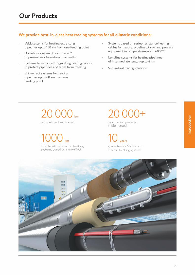
10 yearsguarantee for SST Group electric heating systems
20 000+ heat tracing projects implemented
20 000 km
of pipelines heat traced
1000 kmtotal length of electric heating systems based on skin-effect
Our Products
• VeLL systems for heating extra-long pipelines up to 150 km from one feeding point
• Skin-effect systems for heating pipelines up to 60 km from one feeding point
We provide best-in-class heat tracing systems for all climatic conditions:
• Downhole system Stream Tracer™ to prevent wax formation in oil wells
• Systems based on self-regulating heating cables to protect pipelines and tanks from freezing
• Systems based on series-resistance heating cables for heating pipelines, tanks and process equipment in temperatures up to 600 °C
• Longline systems for heating pipelines of intermediate length up to 4 km
• Subsea heat tracing solutions

Introduction
6
Project design
Manufacturing
Delivery
Installation
Start-up & commissioning
Servicing & post warranty
service
Consulting
Turnkey Heat Tracing Solutions
SST Group provides turnkey solutions in heat tracing, thermal insulation and design engineering, including a full range of all system components and services.
We provide basic and detailed engineering, procurement, delivery, implementation, documentation, service and training.
Thanks to our integrated approach and project implementation control at all phases, our customers can always expect high quality and efficiency of the installed systems.
We have the complete infrastructure required to develop and implement innovative solutions — from product development and manufacturing to installation, start-up & commissioning and post warranty service.

Intr
oduc
tion
7
Research and Development
Manufacturing
Design Engineering
Every year SST Group presents new products and solutions to consumers, created in our own R&D-center. Our team carries out fundamental research, new product developments (including OEM-products and customized products) as well as application-specific tests. This enables us to make evolutionary and revolutionary changes to heat tracing systems and their components.
Extensive manufacturing experience, qualified staff and automated machinery allow to meet the demanding world standards and the highest quality levels.
SST Group is the one of the few global manufacturers of electrically conductive plastics and self-regulating heating cables. We produce a matrix for high, medium, and low temperature cables, which is compatible with heating systems of all global manufacturers.
An in-house R&D-center and engineering team of 100+ design engineers enable SST Group to prepare high-quality design and project documentation. We design heat tracing systems, thermal insulation, and power supply systems for various applications, including explosion hazard areas. Our services include field supervision to ensure that the structural and architectural parameters match the adopted design.
Our Capabilities
Specialized equipment: electron-beam machining (EBM), polymer compounders, testing equipment
Cutting-edge switchboard manufacturing
of production facilities45 000 m2
cable manufacturing capacity60 000 km / year

Introduction
8
We pay special attention to compliance with international standards in the area of quality management system, lean manufacturing, health, safety and environmental protection.
SST Group complies to ISO 9001 since 2004. Our company’s unifi ed quality management system is certifi ed for compliance with ISO 9001:2015, which covers the design, implementation, installation, warranty and post warranty maintenance of heat tracing systems, as well as the production, implementation and installation of switchboard equipment and low-voltage complex equipment.
SST Group production facilities are certifi ed by global EPC contractors, including Total, Petrofac, WorleyParsons, Linde, Technip.
Our company has passed certifi cation by TÜV Rheinland for ISO 14001:2015 environmental management system and complies to all requirements of health and safety standard GOST R 54934-2012 / OHSAS 18001:2007.
Our products have been certifi ed in accordance with international standards by some of the largest European certifi cation centers: CSA Group, VDE, DEKRA and NANIO CCVE. Industrial electric cable heating systems by SST Group comply with the International Electrotechnical Commission’s Standards Relating to Equipment for Use in Explosive Atmospheres (IECEx). Self-regulating heating cables and heat tracing systems based on skin-effect (IRHS-15000) are ATEX-certifi ed. In addition our company holds a number of certifi cates, such as:
Quality Assurance

Intr
oduc
tion
9

10
ECO line
Self-Regulating Heating Cable LTM
1
1
2
2
3
3
4
4
5
5
LTM is an industrial-grade self-regulating heating cable that can be used for freeze protection of pipelines and vessels in non-Ex areas.The power output adjusts automatically in response to the ambient temperature.Due to its self-regulating characteristics it will not overheat even when the cable is overlapped. This guarantees maximum safety and reliability.Installation of LTM heating cable is quick and simple and requires no special skills or tools.
Thanks to its parallel construction the heating cable can be fi tted on site to exact length without any complicated design calculations.The LTM cable with fl ouropolymer outer jacket is characterized by high resistance to high temperatures, chemicals and UV radiation.Termination, splicing and power connection components are available in convenient kits.
1. 0.56 mm2 nickel-plated copper conductors
2. Semi-conductive self-regulating matrix
3. Matrix insulation
4. Aluminum foil with drainage wires or tinned copper braid
5. Thermoplastic or fl uoropolymer outer jacket
Construction
10 or 15 W/m
Self-regulating, automatically adjusts power output in response to ambient temperature
Thermoplastic and fl uoropolymer outer jacket
Easy to install
Can be cut to required length on site without any complicated design calculations
Will not overheat even when overlapped
Full range of accessories available
UV and high chemical resistance (fl uoropolymer)
Features
Freeze protection of pipelines and vessels (non-Ex)
Application Areas

11
ECO
line
Maximum Heating Circuit Length For use with type C circuit breakers according to IEC 60898-1:2015
Technical Data
Power Output CurveNominal power output at rated voltage 230 VAC
MarkingExample: 15LTM-AT
1. Linear power output, W/m at +10 °C2. Cable type3. Screen type: B – tinned copper wire braiding, A – aluminum
foil screen4. Outer jacket material: T – Thermoplastic elastomer,
P – Fluoropolymer
Approvals
Type Turn-on temperature, °C
Heating circuit length/m at 230 VAC 10 A
10LTM10 88-20 68Inside pipe 60
15LTM10 63-20 46
Rated voltage 230 VACMaximum continuous operating temperature (trace heater energized) +65 °С
Maximum continuous exposure temperature (trace heater de-energized) +85 °С
Ambient temperature range –60 … +55 °СMinimum installation temperature:Thermoplastic outer jacketFluoropolymer outer jacket
-30 °C-60 °C
Minimum bending radius 25 mmMaximum screen resistance 18 Ohm/kmMaximum braiding resistance 10 Ohm/kmConductor cross-section 0.56 mm2
Dimension:Thermoplastic elastomer outer jacket,aluminum foil 8.30×5.50 mmFluoropolymer outer jacket, braiding 8.60×5.40 mm
Weight:Thermoplastic elastomer outer jacket,aluminum foil 66 kg/kmFluoropolymer outer jacket, braiding 98 kg/km
Types
Outer jacket type Order code
Outer jacket color
NamePower output,
W/mThermoplastic elastomer outer jacket, aluminum foil
1101000000Black
10LTM-AT 10
1101000001 15LTM-AT 15
Fluoropolymer outer jacket, braiding
1101000004Blue
10LTM-BP 10
1101000005 15LTM-BP 15
Line
ar p
ower
out
put,
W/m
Pipe temperature, °С
10LTM
10 20 30 40 50 60 6500
5
10
15
25
20
15LTM
3 421
Self-Regulating Heating Cables

12
ECO line
Self-Regulating Heating Cable LTL
LTL is an industrial-grade self-regulating heating cable that can be used for freeze protection of pipelines and vessels and also for snow and ice prevention on roofs and gutters in non-hazardous areas.The power output adjusts automatically in response to the ambient temperature.Due to its self-regulating characteristics it will not overheat even when the cable is overlapped. This guarantees maximum safety and reliability.
Installation of LTL heating cable is quick and simple and requires no special skills or tools. Thanks to its parallel construction the heating cable can be fi tted on site to exact length without any complicated design calculations.Termination, splicing and power connection components are available in convenient kits.
15, 20, 25 or 30 W/m
Self-regulating, automatically adjusts power output in response to ambient temperature
Thermoplastic outer jacket
Easy to install
Can be cut to required length on site without any complicated design calculations
Will not overheat even when overlapped
Full range of accessories available
UV-resistant
Features
Freeze protection of pipelines and vessels (non-Ex)
Snow and ice prevention on roofs and gutters (non-Ex)
Application Areas
1
1
2
2
3
3
4
4
5
5
1. 1.00 mm2 nickel-plated copper conductors
2. Semi-conductive self-regulating matrix
3. Matrix insulation
4. Aluminum foil with drainage wire or tinned copper braid
5. Thermoplastic outer jacket
Construction

13
ECO
line
Technical Data
MarkingExample: 15LTL-BT
1. Linear power output, W/m at +10 °C2. Cable type3. Screen type: B – tinned copper wire braiding, A – aluminum
foil screen4. Outer jacket material: T – Thermoplastic elastomer
Type Turn-on temperature, °C
Heating circuit length/m at 230 VAC 10 A 16 A
15LTL10 92 120-20 51 69
20LTL10 70 97-20 37 51In gutters 60 80
25LTL10 53 73-20 28 41
30LTL10 40 62-20 18 35
Rated voltage 230 VACMaximum continuous operating temperature (trace heater energized) +65 °С
Maximum continuous exposure temperature (trace heater de-energized) +85 °С
Ambient temperature range –60 … +55 °СMinimum installation temperature:Thermoplastic outer jacket -30 °CMinimum bending radius 25 mmMaximum screen resistance 18 Ohm/kmMaximum braiding resistance 10 Ohm/kmConductor cross-section 1.00 mm2
Dimension:Thermoplastic elastomer outer jacket,aluminum foil 10.20×5.70 mmThermoplastic elastomer outer jacket,braiding 10.90×6.00 mm
Weight:Thermoplastic elastomer outer jacket,aluminum foil 86 kg/kmThermoplastic elastomer outer jacket,braiding 113 kg/km
Maximum Heating Circuit Length For use with type C circuit breakers according to IEC 60898-1:2015
Approvals
Types
Outer jacket type Order code
Outer jacket color
NamePower output,
W/m
Thermoplastic elastomer outer jacket, aluminum foil
1101001000
Black
15LTL-AT 151101001001 20LTL-AT 201101001002 25LTL-AT 251101001003 30LTL-AT 30
Thermoplastic elastomer outer jacket, braiding
1101001004
Black
15LTL-BT 151101001005 20LTL-BT 201101001006 25LTL-BT 251101001007 30LTL-BT 30
Power Output CurveNominal power output at rated voltage 230 VAC
Line
ar p
ower
out
put,
W/m
Pipe temperature, °С
30LTL
25LTL
20LTL
15LTL
10 20 30 40 50 60 6500
5
10
15
20
25
30
35
403 421
Self-Regulating Heating Cables

14
ECO line
Self-Regulating Heating Cable LTR
1
1
2
2
3
3
4
4
5
5
LTR is an industrial-grade self-regulating heating cable that can be used for freeze protection of pipelines and vessels and also for snow and ice prevention on roofs and gutters in non-hazardous areas.The power output adjusts automatically in response to the ambient temperature.Due to its self-regulating characteristics it will not overheat even when the cable is overlapped. This guarantees maximum safety and reliability.
Installation of LTR heating cable is quick and simple and requires no special skills or tools. Thanks to its parallel construction the heating cable can be fi tted on site to exact length without any complicated design calculations.Termination, splicing and power connection components are available in convenient kits.
1. 1.25 mm2 nickel-plated copper conductors
2. Semi-conductive self-regulating matrix
3. Matrix insulation
4. Aluminum foil with drainage wires or tinned copper braid
5. Thermoplastic or fl uoropolymer outer jacket
Construction
10, 20, 30 or 40 W/m
Self-regulating, automatically adjusts power output in response to ambient temperature
Thermoplastic and fl uoropolymer outer jacket
Easy to install
Can be cut to required length on site without any complicated design calculations
Will not overheat even when overlapped
Full range of accessories available
UV and high chemical resistance (fl uoropolymer)
Features
Freeze protection of pipelines and vessels (non-Ex)
Snow and ice prevention on roof and gutters (non-Ex)
Application Areas

15
ECO
line
Maximum Heating Circuit Length For use with type C circuit breakers according to IEC 60898-1:2015
Technical Data
Power Output CurveNominal power output at rated voltage 230 VAC
Approvals
MarkingExample: 15LTR-BT
1. Linear power output, W/m at +10 °C2. Cable type3. Screen type: B – tinned copper wire braiding, A – aluminum
foil screen4. Outer jacket material: T – Thermoplastic elastomer,
P – Fluoropolymer
Type Turn-on temperature, °C
Heating circuit length/m at 230 VAC 16 A
10LTR10 180–20 108
20LTR10 102–20 53In gutters 65
30LTR10 62–20 40
40LTR10 49–20 27
Line
ar p
ower
out
put,
W/m
Pipe temperature, °С
Rated voltage 230 VACMaximum continuous operating temperature (trace heater energized) +65 °С
Maximum continuous exposure temperature (trace heater de-energized) +85 °С
Ambient temperature range –60 … +55 °СMinimum installation temperature:Thermoplastic outer jacketFluoropolymer outer jacket
-30 °C-60 °C
Minimum bending radius 25 mmMaximum screen resistance 18 Ohm/kmMaximum braiding resistance 10 Ohm/kmConductor cross-section 1.25 mm2
Dimension:Thermoplastic elastomer outer jacket,aluminum foil 12.50×5.80 mmThermoplastic elastomer outer jacket,braiding 13.20×6.10 mmFluoropolymer outer jacket, braiding 12.80×5.70 mm
Weight:Thermoplastic elastomer outer jacket,aluminum foil 106 kg/kmThermoplastic elastomer outer jacket,braiding 141 kg/kmFluoropolymer outer jacket, braiding 152 kg/km
Types
Outer jacket type Order code
Outer jacket color
NamePower output, W/m
Thermoplastic elastomer outer jacket, aluminum foil
1101002000
Black
10LTR-AT 101101002002 20LTR-AT 201101002004 30LTR-AT 301101002005 40LTR-AT 40
Thermoplastic elastomer outer jacket, braiding
1101002006
Black
10LTR-BT 101101002008 20LTR-BT 201101002010 30LTR-BT 301101002011 40LTR-BT 40
Fluoropolymer outer jacket, braiding
1101002012
Blue
10LTR-BP 101101002014 20LTR-BP 201101002016 30LTR-BP 301101002017 40LTR-BP 40
30LTR
40LTR
20LTR
10LTR
10 20 30 40 50 656000
5
10
15
20
25
30
35
40
50
45
3 421
Self-Regulating Heating Cables

16
ECO line
Junction Box ECO CB
Wall-mounted Non-flammable Silicone- and halogene-free Quick and easy installation
Junction box ECO CB is suitable to connect 1 or 2 self-regulating heating cables to a mains power supply. It can be used for indoor as well as protected outdoor applications in non-hazardous areas.
Features
Technical DataDegree of protection IP66Ambient temperature range -25 . . . +40 °CRated current 32 ARated voltage 230 VACDimensions 104×104×70 mmWeight 0.158 kgMaterial polypropylene Color gray
Terminal BlockRated connecting capacity 1.5–6 mm2, CuTightening torque 0.7 Nm
Rated connecting capacity mm2 and types of conductors
Conductors to be connected per pole
6 sol/f* 1–24 sol/f 1–42.5 sol/f 1–61.5 sol/f 1–8
* sol – solid conductor; f – flexible conductor with a finer wire diameter.
104
118
104
118
32
230 VAC
PE
230 VAC
PE
1x 2x
Wiring Diagram
Approvals
Types
Type Order сode Connection kit
Cable glands
Size Number
ECO CB 1110001001 - M25x1,5 1
ECO CB1 1110001002 ECO SCK-S M25x1,5 1
ECO CB2 1110001003 ECO SCK-D M25x1,5 1
Marking
Example: ECO CBX
1. Connection box type2. X – box model (blank, 1 and 2)
21

17
ECO
line
Control of the heated surface temperature Control of the ambient temperature
Features
Switching temperature values (on / off) +2 . . . +5 °COperating temperature range -55 . . . +60 °CSensing element type digitalNumber of cores in connection cable 3Length of the installation wire 5 mMaximum sensor distance from the controller 100 mCompatible with thermostat type PT-300
Temperature sensor TST04 is designed to measure temperature and transmit a control signal to the controller. TST04 is programmed at the factory for a specified maintenance temperature. Hence,
reprogramming the temperature is not possible. Temperature sensor TST04 can be used only with PT-300 controller. It can be used to measure the temperature of hard surfaces and air.
Temperature Sensor TST04
Technical Data
Freeze protection of pipelines and vessels (non-Ex)
Application Areas
Construction
Approvals TypesName Order code
Temperature sensor TST04 2121001000

18
ECO line
Capillary Thermostat heatTHERM-AT
Stable switching point position due to ambient temperature compensation (standard)
Maximum switching capacity 16 A, 230 V
Tested according to DIN EN 14597
Operating life at least 250,000 switching cycles
Switching point deviation during the entire operating life of up to ± 5 %
Protection type IP54
Freeze protection of pipelines and vessels (non-Ex)
heatTHERM-AT capillary thermostat can be used to controll electric cable heating systems for freeze protection of pipelines and vessels. The thermostat controls the electric cable heating system according to the ambient temperature.heatTHERM-AT is a temperature monitor (TW). When the temperature of the sensing element falls below
the setting point, a micro switch trips the transmis-sion mechanism and the power circuit closes. At the same time, the signal circuit is opened. If the temper-ature of the sensing element exceeds the set value (switching differential), the micro switch trips, open-ing the power circuit. The signal circuit, in turn, closes.
Construction
Features
Application Areas

19
ECO
line
Technical Data ApprovalsTemperature setting range -10 … +40 °C
Maximum switching capacity
contact deck 1-2AC 230 V +10%, 16 (2.5) A, cos φ = 1 (0.6)contact deck 1-4AC 230 V +10 %, 2 (04) A, cos φ = 1 (0.6)
Hysteresis Approx. 2.5 %Protection type IP54Weight Approx. 200 gCable inlet Cable gland M20×1.5, for cable ø6-12 mmAmbient temperature range -30 … +80 °C
Diameter of probe 17 mm coiled probeCapillary material Stainless steel (CrNi)
DimensionWithout cable glands and probe120×53×58 mmIncluded cable glands and probe160×80×58 mm
Installation type Surface mounted
Function Diagram
Wiring Diagram
On
t°C
∆t°
t set
PE 1 2 442
θ>1
TypesName Order code
Jumo heatTHERM-AT(-10…+40) 1120001001
MarkingExample: heatTHERM-AT(-10…+40)
1. Type of thermostat2. Control temperature range
21
Measuring and Control Equipment

20
ECO line
The electronic temperature controller is designed to maintain the temperature in the set range.
PT-300 is used in general-purpose industrial electric heating systems of pipelines and tanks, in de-icing systems, as well as for maintaining a positive temperature in control cabinets within the set temperature range. The required temperature range corresponds to the selected pre-programmed TST04
temperature sensor. The sensor is programmed at the factory and cannot be reprogrammed.The regulator, in conjunction with the connected temperature sensor TST04, maintains the temperature according to the factory setting and does not require any settings for installation and operation.The on/off button allows to switch off the heating system when it is not needed.
Easy operation
Small size
Max. switching capacity 8 A
Maintenance of set temperature without additional adjustments
Indication of power and heating status
Parameter storage in non-volatile memory
Relay changeover contact
Electronic Temperature Controller РТ-300
Features
Freeze protection of pipelines and vessels
Construction
Application Areas

21
ECO
line
Technical DataTemperature setting range set by sensor TST04Supply voltage ~220 V, 50 HzPower consumption 0,5 WDimensions 35×90×68 mmWeight 100 gOperating temperature +5 . . . +45 °CRelative humidity 80 %Degree of protection IP20Mounting type DIN-rail, 2 modulesType of temperature sensor* TST04Maximum sensor distance from the controller up to 100 m
Number of temperature measurement channels 1
Number of control channels 1 Switching capacity 8 ATemperature measurement accuracy ±0.5 °C
Wiring Diagram
P
100%
0%
N%
t Surface sett Air currentt Air min
t On t Off
On
Off
0
On
Off
40%24
min.
60%36
min.
1 cycle = 100%60 min.
Т, min.36 60 96
Р set. = 60%
On
Off
Off
t Set
On
0
t⁰Ct⁰C
t⁰C
t⁰C
+5 ⁰Ct Set-15 ⁰C
Δt⁰
Δt Set
* The sensor is not included in the scope of supply and must be ordered separately
Temperature sensor
Load
L
N~220 VDATA
GND +5 V
8NO NC
7 6 5 4
1 2 3
Temperature sensor
Load
L
N~220 VDATA
GND +5 V
8NO NC
7 6 5 4
1 2 3
Measuring and Control Equipment
Function Diagram
Approvals
Types
Accessories
Name Order code
Electronic temperature controller РТ-300 1120004000
Name Order code
Temperature sensor TST04 (in the required configuration) 1121001000

22
ECO line
Accessories
SST accessories are perfectly suited to use with the self-regulating heating cables LTM, LTL and LTR and are available in a wide range of different versions for every application. There are connection kits, end
termination kits, repair kits and junction boxes available. All components are combined in sets to ensure an easy and reliable installation on site.
Easy and quick installation
Wide range of kits available
Suitable perfectly with ECO self-regulating heating cables
“Ready to install” solutions
UV-resistant
Features
Freeze protection of pipelines and vessels (non-Ex)
Application Areas
VariationsConnection of one or two self-regulating heating cables to a box, including end termination
ECO junction box CB
ECO connection kit SCK-S (S=single)
ECO end termination kit Con-ET

23
ECO
line
TypesName Order code
ECO CB 1110001001
ECO CB-1 1110001002
ECO CB-2 1110001003
ECO SCK-S 1101100000
ECO SCK-D 1101100001
ECO Con-ET 2101100200
ECO HSRK 1101100002
Approvals
Variations
Connection Kit vs. Heating Cable Type
NameMaximum exposure tem-perature, °C
Ref. type of self-regulating heating tape
ECO SCK-S/D 85 LTM, LTL, LTR
ECO Con-ET 85 LTM, LTL, LTR
ECO HSRK 85 LTM, LTL, LTR
Repair kit
ECO repair kit HSRK
Set amount type amount type
ECO CB-1 1x ECO CB 1x ECO SCK-S
ECO CB-2 1x ECO CB 1x ECO SCK-DECO connection kit SCK-D (D=double)
Set Components
Accessories

24
CLASSIC line
Self-Regulating Heating Cable VTM
1 2
3 4
5
1. 0.56 mm2 nickel-plated copper conductors
2. Semi-conductive self-regulating matrix
3. Matrix insulation
4. Tinned copper braid
5. Thermoplastic outer jacket
Construction
15 W/m
Self-regulating, automatically adjusts power output in response to ambient temperature
Thermoplastic outer jacket
Easy to install
Can be cut to required length on site without any complicated design calculations
Will not overheat even when overlapped
UV-resistant
VDE certifi ed
Features
VTM is an industrial-grade self-regulating heating cable that can be used for freeze protection of pipelines and vessels.The power output adjusts automatically in response to the ambient temperature.Due to its self-regulating characteristics it will not overheat even when the cable is overlapped. This guarantees maximum safety and reliability.
Installation of VTM heating cable is quick and simple and requires no special skills or tools. Thanks to its parallel construction the heating cable can be fi tted on site to exact length without any complicated design calculations.Termination, splicing and power connection components are available in convenient kits.
Application Areas Freeze protection of pipelines and vessels (non-Ex)

25
CLA
SSIC
line
Maximum Heating Circuit Length For use with type C circuit breakers according to IEC 60898-1:2015
Technical Data
MarkingExample: 15VTM-BT
1. Linear power output, W/m at +10 °C2. Cable type3. Screen type: B – Tinned copper wire braiding4. Outer jacket material: T – Thermoplastic elastomer
Rated voltage 230 VACMaximum continuous operating temperature (trace heater energized) +65 °С
Maximum continuous exposure temperature (trace heater de-energized) +85 °С
Ambient temperature range –60 … +55 °СMinimum installation temperature:Thermoplastic outer jacket -30 °CMinimum bending radius 25 mmMaximum braiding resistance 10 Ohm/kmConductor cross-section 0.56 mm2
Dimension:Thermoplastic elastomer outer jacket,braiding 9.00×5.80 mm
Weight:Thermoplastic elastomer outer jacket,braiding 91 kg/km
Type Turn-on temperature, °C
Heating circuit length/m at 230 VAC 10A
15VTM10 68-20 49
Types
Outer jacket type Order code Outer jacket
color NamePower output, W/m
Thermoplastic elastomer outer jacket, braiding
2101000003 Black 15VTM-BT 15
Approvals
Line
ar p
ower
out
put,
W/m
Power Output CurveNominal power output at rated voltage 230 VAC
Pipe temperature, °С0 10 20 30 40 50 60 65
0
5
10
15
20
25
15VTM
3 421
Self-Regulating Heating Cables

26
CLASSIC line
Self-Regulating Heating Cable VTL
1. 1.00 mm2 nickel-plated copper conductors
2. Semi-conductive self-regulating matrix
3. Matrix insulation
4. Aluminum foil with drainage wire or tinned copper braid
5. Thermoplastic outer jacket
Construction
15, 20 or 30 W/m
Self-regulating, automatically adjusts power output in response ambient temperature
Thermoplastic outer jacket
Easy to install
Can be cut to required length on site without any complicated design calculations
Will not overheat even when overlapped
UV-resistant
VDE certifi ed
Features
VTL is an industrial-grade self-regulating heating cable that can be used for freeze protection of pipelines and vessels and also for snow and ice prevention on roofs and gutters.The power output adjusts automatically in response to the ambient temperature.Due to its self-regulating characteristics it will not overheat even when the cable is overlapped. This guarantees maximum safety and reliability.
Installation of VTL heating cable is quick and simple and requires no special skills or tools. Thanks to its parallel construction the heating cable can be fi tted on site to exact length without any complicated design calculations.Termination, splicing and power connection components are available in convenient kits.
Application Areas Freeze protection of pipelines and vessels
(non-Ex) Snow and ice prevention on roof and gutters
(non-Ex)
1 2
3 4
5
1 2
3 4
51 2
3 4

27
CLA
SSIC
line
Technical Data
MarkingExample: 15VTL-BT
1. Linear power output, W/m at +10 °C2. Cable type3. Screen type: B – Tinned copper wire braiding, A – Aluminum
foil screen4. Outer jacket material: T – Thermoplastic elastomer
Rated voltage 230 VACMaximum continuous operating temperature (trace heater energized) +65 °С
Maximum continuous exposure temperature (trace heater de-energized) +85 °С
Ambient temperature range –60 … +55 °СMinimum installation temperature:Thermoplastic outer jacket -30 °CMinimum bending radius 25 mmMaximum screen resistance 18 Ohm/kmMaximum braiding resistance 10 Ohm/kmConductor cross-section 1.00 mm2
Dimension:Thermoplastic elastomer outer jacket,aluminum foil 10.20×5.70 mmThermoplastic elastomer outer jacket,braiding 10.90×6.00 mm
Weight:Thermoplastic elastomer outer jacket,aluminum foil 86 kg/kmThermoplastic elastomer outer jacket,braiding 113 kg/km
Type Turn-on temperature, °C
Heating circuit length/m at 230 VAC
10A 16 A
15VTL10 98 128-20 55 73
20VTL10 74 103-20 39 55In gutters 60 80
30VTL10 42 66-20 19 38
Types
Outer jacket type Order code Outer
jacket color NamePower output, W/m
Thermoplastic elastomer outer jacket, aluminum foil
2101001000
Black
15VTL-AT 15
2101001001 20VTL-AT 20
2101001003 30VTL-AT 30
Thermoplastic elastomer outer jacket, braiding
2101001004
Black
15VTL-BT 15
2101001005 20VTL-BT 20
2101001007 30VTL-BT 30
Maximum Heating Circuit Length For use with type C circuit breakers according to IEC 60898-1:2015
Approvals
Line
ar p
ower
out
put,
W/m
Pipe temperature, °С0 10 20 30 40 50 6560
0
5
10
15
20
25
30
35
40
15VTL
Power Output CurveNominal power output at rated voltage 230 VAC
3 421
Self-Regulating Heating Cables

28
CLASSIC line
Self-Regulating Heating Cable VTR
1. 1.25 mm2 nickel-plated copper conductors
2. Semi-conductive self-regulating matrix
3. Matrix insulation
4. Tinned copper braid
5. Thermoplastic outer jacket
Construction
10, 20, 30 or 40 W/m
Self-regulating, automatically adjusts power output in response to ambient temperature
Thermoplastic outer jacket
Easy to install
Can be cut to required length on site without any complicated design calculations
Will not overheat even when overlapped
UV-resistant
VDE certifi ed
Features
VTR is an industrial-grade self-regulating heating cable that can be used for freeze protection of pipelines and vessels and also for snow and ice prevention on roofs and gutters.The power output adjusts automatically in response to the ambient temperature.Due to its self-regulating characteristics it will not overheat even when the cable is overlapped. This guarantees maximum safety and reliability.
Installation of VTR heating cable is quick and simple and requires no special skills or tools. Thanks to its parallel construction the heating cable can be fi tted on site to exact length without any complicated design calculations.Termination, splicing and power connection components are available in convenient kits.
Application Areas Freeze protection of pipelines and vessels
(non-Ex) Snow and ice prevention on roof and gutters
(non-Ex)
1 2
3 4
51 2
3 4

29
CLA
SSIC
line
Maximum Heating Circuit Length For use with type C circuit breakers according toIEC 60898-1:2015
Technical Data
MarkingExample: 10VTR-BT
1. Linear power output, W/m at +10 °C2. Cable type3. Screen type: B – Tinned copper wire braiding4. Outer jacket material: T – Thermoplastic elastomer
Types
Outer jacket type Order code Outer
jacket color NamePower output, W/m
Thermoplastic elastomer outer jacket,braiding
2101002006
Black
10VTR-BT 102101002008 20VTR-BT 202101002010 30VTR-BT 302101002011 40VTR-BT 40
Approvals
Rated voltage 230 VACMaximum continuous operating temperature (trace heater energized) +65 °С
Maximum continuous exposure temperature (trace heater de-energized) +85 °С
Ambient temperature range –60 … +55 °СMinimum installation temperature:Thermoplastic outer jacket -30 °CMinimum bending radius 25 mmMaximum braiding resistance 10 Ohm/kmConductor cross-section 1.25 mm2
Dimension:Thermoplastic elastomer outer jacket,braiding 13.20×6.10 mm
Weight:Thermoplastic elastomer outer jacket,braiding 141 kg/km
Power Output CurveNominal power output at rated voltage 230 VAC
Line
ar p
ower
out
put,
W/m
Pipe temperature, °С0 10 20 30 40 50 60 65
0
5
10
15
20
25
30
35
40
45
50
10VTR
20VTR
30VTR
40VTR
Type Turn-on temperature, °C
Heating circuit length/m at 230 VAC 16 A
10VTR10 193-20 116
20VTR10 109-20 56in gutters 65
30VTR10 66-20 42
40VTR10 53-20 29
3 421
Self-Regulating Heating Cables

30
CLASSIC line
Junction Box for Self-Regulating Heating Cables to Power Connection with Pipe Installation Support
Junction box for self-regulating heating cables is designed for connection of self-regulating heating cables to power network. The junction box is equipped with a pipe installation support stand UVK which allows fi xation of the junction box directly onto the pipeline. The junction box is used as part of cable heat trace systems for pipelines and vessels in non-hazardous areas. The junction box design ensures
moisture and dust ingress protection IP66 and high corrosion stability. The junction box is available with cable glands for connection of unarmored power cables. The installed terminal blocks ensure fast and safe connection of multi-core or single-core conductors. Our boxes are available with screw clamp terminals as well as with push-in terminals.
Features Non-hazardous approved solution
Perfect solution for installation of self-regulating heating cables through thermal insulation
Excludes the risk of damage to heating cables
All required component parts are included
Quick and easy installation
High thermal stability
Non-corrosive
JB2212-223-1xxxx 1. Power cable2. JB2212-223-1xxxx junction box 3. Heating cable4. Pipe support stand UVK
12
3
Temperature maintenance or freeze protection of pipelines and vessels in non-hazardous areasApplication Areas
4

31
CLA
SSIC
line
Construction
JB2212-223-1xxxx box with screw clamp terminal block JB2212-223-1xxxx box with push-in terminals block
Technical DataDegree of protection IP66Ambient temperature range -55. . .+55 °С Operating voltage max. 750 VOperating current max. 32 AEnclosure dimensions 122×120×90 mmTotal weight (maximum) 1.35 kg
Material box Glass fiber reinforced polyester
Color GreyPipe installation support material
Glass fiber reinforced polyester
Color Black
TypesName Order code
JB2212-223-11310 2210001610
JB2212-223-12310 2210001611
JB2212-223-11300 2210001608
JB2212-223-12300 2210001609
Approvals
* All junction boxes for power connection are equipped with a cable gland M25×1,5 for the power cable and terminial jumpers L-L, N-N
* Certification is underway
Application TypesApplication Terminals Name
Heating cable branching*
screw, 2L, 2N, 2PE JB2212-223-11310
push-in, 2L, 2N, 2PE JB2212-223-12310
Power connection*screw, 2L, 2N, 2PE JB2212-223-11300
push-in, 2L, 2N, 2PE JB2212-223-12300
Accessories (to be ordered separately)Metal pipe strap PFS/3 – for mounting the box onto the pipeline. For ordering information see “Accessories”, p. 117.The heating cable termination kit is specified depending on the type of cable used. For ordering information see CLASSIC-CON units, pp. 46-47.Flexible sealed gland FSG – for mechanical protection of cables in open space sets. For ordering information see pp. 92-93.
*
Junction Boxes

32
CLASSIC line
Junction Box for Self-Regulating Heating Cables to Power Connection
Junction box for self-regulating heating cables is designed for connection of self-regulating heating cables to power network. The junction box is used as a part of heat tracing systems for pipelines and vessels in non-hazardous areas. The junction box design ensures moisture and dust ingress protection IP66 and high corrosion stability. The junction box is
available with cable glands for connection of unarmored power and heating cables. The installed terminal blocks ensure fast and safe connection of multi-core or single-core conductors. Our boxes are available with screw clamp terminals as well as with push-in terminals.
Features Non-hazardous area solution
All required component parts are included
Quick and easy installation
High thermal stability
Non-corrosive
JB2212-223-2xxxx 1. Power cable2. JB2212-223-2xxxx junction box3. Heating cable4. Flexible sealed gland5. Cable entry unit
1
2
3
4
5
Temperature maintenance or freeze protection of pipelines and vessels in non-hazardous and ex-hazardous areas
Application Areas

33
CLA
SSIC
line
Technical DataDegree of protection IP66Ambient temperature range -55. . .+55 °С Operating voltage max. 750 VOperating current max. 32 AEnclosure dimensions 122×120×90 mmTotal weight (maximum) 1.1 kg
Box material Glass fiber reinforced polyester
Color Grey
Construction
JB2212-223-2xxxx box with screw clamp terminal block JB2212-223-2xxxx box with push-in terminal block
TypesName Order codeJB2212-223-21340 2210001600
JB2212-223-22340 2210001601
JB2212-223-21350 2210001602
JB2212-223-22350 2210001603
JB2212-223-21360 2210001604
JB2212-223-22360 2210001605
JB2212-223-21370 2210001606JB2212-223-22370 2210001607
Application TypesApplication1 heating cable Terminals Name
Power connection2x M25 x 1,5
screw, 1L, 1N, 2PE JB2212-223-21340
push-in, 1L, 1N, 2PE JB2212-223-22340Connection1x M25 x 1,51x M25x1,5 screw plug
screw, 1L, 1N, 2PE JB2212-223-21350
push-in, 1L, 1N, 2PE JB2212-223-22350Application3 heating cable Terminals Name
Power connection*4x M25 x 1,5
screw, 3L, 3N, 3PE JB2212-223-21360
push-in, 3L, 3N, 3PE JB2212-223-22360Connection*1x M25 x 1,53x M25x1,5 screw plug
screw, 3L, 3N, 3PE JB2212-223-21370
push-in, 3L, 3N, 3PE JB2212-223-22370
Accessories (to be ordered separately)Brackets PB, KP, PL.JB0606 – for mounting the box onto the pipeline. For ordering information see “Accessories”, pp. 112-113.Z-profile – for mounting the box onto a metal structure or onto a wall.The heating cable termination kit is specified depending on the type of cable used. For ordering information see CLASSIC-CON units, pp. 46-47.Flexible sealed gland FSG – for mechanical protection of cables in open space sets. For ordering information see pp. 92-93.Cable entry unit LEK/U – for penetrating of thermal insulation. For ordering information see “Accessories”, p. 111.
Approvals
* With jumper L-L, N-N
Junction Boxes
* Certification is underway
*

34
CLASSIC line
Junction Box for Light Indication
The junction box for light indication is designed for the purpose of light indication and connection of self-regulating heating cables to power network. The junction box is used as a part of heat tracing systems for pipelines and vessels in non-hazardous areas. The junction box is equipped with a pipe installation support stand UVK which allows fi xation directly
onto the pipeline/vessel. The junction box design ensures moisture and dust ingress protection IP66 and high corrosion stability. The installed terminal blocks ensure fast and safe connection of multi-core or single-core conductors. Our boxes are available with screw clamp terminals as well as with push-in terminals.
Features Non-hazardous area approved solution
Excludes the risk of damage to heating cables
All required component parts are included
Quick and easy installation
High thermal stability
Non-corrosive
JB2212-223-1xxxx 1. JB2212-223-1xxxx junction box2. Heating cable3. Pipe support stand UVK
Temperature maintenance or freeze protection of pipelines and vessels in non-hazardous areas
Application Areas
1
2
3

35
CLA
SSIC
line
Construction
JB2212-223-1xxxx box with screw clamp terminal block JB2212-223-1xxxx box with push-in terminal block
Technical DataDegree of protection IP66Ambient temperature range -55. . .+55 °С Operating voltage on terminals max. 750 VMaximum voltage on light module 250 VOperating current max. 32 AElectric lamp lifetime > 105 hLamp consuming power < 1 WLight source green LEDLight coverage 180°Enclosure dimensions 122×120×90 mmTotal weight (maximum) 1.35 kg
Material box Glass fiber reinforced polyester
Color Grey
Pipe installation support material Glass fiber reinforced polyester
Color Black
TypesName Order code
JB2212-223-11320 2210001612
JB2212-223-12320 2210001613
Accessories (to be ordered separately)Application types
Approvals
Application Terminals Name
Light ind. end boxscrew, 1L, 1N, 1PE JB2212-223-11320
push-in, 1L, 1N, 1PE JB2212-223-12320
Metal pipe strap PFS/3 – for mounting the box onto the pipeline. For ordering information see “Accessories”, p. 117.
Junction Boxes
* Certification is underway
*

36
CLASSIC line
Junction Box for Series-Resistance Heating Cables
Temperature maintenance or freeze protection of pipelines and vessels in non-hazardous areas
Application Areas
Features Non-hazardous area approved solution
Perfect solution for installation of series-resistance cables SNF through thermal insulation
Excludes the risk of damage to heating cables
JB2212-. . .-2xxxx
All required component parts are included
Quick and easy installation
High thermal stability
Non-corrosive
1. Power cable2. JB2212-. . .-2xxxx junction box3. Heating cable4. Connection cable (cold lead)5. Bracket
1
2
3
45
The junction box for series-resistance heating cables SNF is designed for connection of heating cables to power network. The junction box could be mounted on a wall of a building or using a bracket directly on a pipe/vessel surface. The box enables connection of SNF cable heating sections to power cable. The junction box is used as a part of heat tracing systems for pipelines and vessels in non-hazardous areas.
The junction box design ensures moisture and dust ingress protection IP66 and high corrosion stability. The junction box is available with cable glands for connection of unarmored power and heating cables. The installed terminal blocks ensure fast and safe connection of multi-core or single-core conductors. The boxes are available with screw clamp terminals as well as with push-in terminals.

37
CLA
SSIC
line
Technical DataDegree of protection IP66Ambient temperature range -55. . .+55 °С Operating voltage max. 750 V
Operating current JB2212-223. . . max. 32 AJB2212-333. . . max. 50AJB2212-523. . . max. 50A
Dimensions enclosure
JB2212-223. . . 122×120×90 mmJB2212-333. . . 160×160×90 mmJB2212-533. . . 260×160×90 mm
Weight JB2212-223. . 1.2 kgJB2212-333. . . 1.8 kgJB2212-533. . . 2.2 kg
Box material Glass fiber reinforced polyester
Color Grey
Construction
JB2221-223-2xxxx box with screw clamp (left) and push-in (right) terminal block. Number of terminals and cable glands could differ from drawings.
TypesName Order code
JB2212-223-21380 2210001614
JB2212-223-22380 2210001615
JB2212-333-21380 2210001618
JB2212-333-22380 2210001619
JB2212-533-21130 2210001622
JB2212-533-22130 2210001623
Accessories (to be ordered separately)Application types
Approvals
Application Loop to PowerJB2221-223-2xxxx
Terminals Name
1x M25x1.52x M20x1.5
screw, 1L, 1N, 2PE JB2212-223-21380
push-in, 1L, 1N, 2PE JB2212-223-22380Application Star to PowerJB2221-333-2xxxx
Terminals* Name
1x M25x1.53x M20x1.5
screw, 3L, 3N, 2PE JB2212-333-21380
push-in, 3L, 3N, 2PE JB2212-333-22380Application Delta to PowerJB2221-533-2xxxx
Terminals** Name
1x M25x1.56x M20x1.5
screw, 7L, 6PE JB2212-533-21130
push-in, 7L, 6PE JB2212-533-22130
Brackets PB, KP, PL.JB0606 – for mounting the box onto the pipeline. For ordering information see “Accessories”, pp. 112-113.Z-profile – for mounting the box onto a metal structure or onto a wall.Metal pipe strap PFS/3 – for mounting the bracket onto a pipeline. For ordering information see “Accessories”, p. 117.Flexible sealed gland FSG – for mechanical protection of cables in open space sets. For ordering information see pp. 92-93.Cable entry unit LEK/U – for penetrating of thermal insulation. For ordering information see “Accessories”, p. 111.
* Terminal jumpers L-L-L and N-N-N** Terminal jumpers L-L and L-L-L
Junction Boxes
* Certification is underway
*

38
CLASSIC line
Junction Box for Mineral-Insulated Heating Cables
The junction box for heating mineral-insulated cables is designed for connection of mineral-insulated (MI) heating cables to power network. The junction box could be mounted on a wall of a building or using a bracket directly on a pipe/vessel surface. The box enables connection of one mineral-insulated cable heating section to power cable. The junction box is used as a part of heat tracing systems for pipelines and vessels in non-hazardous areas. The junction box
design ensures moisture and dust ingress protection IP66 and high corrosion stability. The junction box is available with cable glands for connection of unarmored power cables. The installed terminal blocks ensure fast and safe connection of multi-core or single-core conductors. The boxes are available with screw clamp terminals as well as with push-in terminals.
Features Non-hazardous area solution
All required component parts are included
Quick and easy installation
High thermal stability
Non-corrosive
JB2212-. . .-2xxxx 1. Power cable2. JB2212-. . .-2xxxx junction box3. Heating cable4. Connection cable (cold lead)5. Bracket
Temperature maintenance or freeze protection of pipelines and vessels in non-hazardous areas
Application Areas
1
2
3
45

39
CLA
SSIC
line
Construction
Accessories (to be ordered separately)
Approvals
Brackets PB, KP, PL.JB0606 – for mounting the box onto the pipeline. For ordering information see “Accessories”, pp. 112-113.Z-profile – for mounting the box onto a metal structure or onto a wall.Metal pipe strap PFS/3 – for mounting the bracket onto a pipeline. For ordering information see “Accessories”, p. 117.Flexible sealed gland FSG – for mechanical protection of cables in open space sets. For ordering information see pp. 92-93.Cable entry unit LEK/U – for penetrating of thermal insulation. For ordering information see “Accessories”, p. 111.
Application typesApplication Loop to PowerJB2221-223-2xxxx
Terminals Name
1x M25x1.52x M20x1.5 screw plug
screw, 1L, 1N, 2PE JB2212-223-21390
push-in, 1L, 1N, 2PE JB2212-223-22390Application Star to PowerJB2221-333-2xxxx
Terminals* Name
1x M25x1.53x M20x1.5 screw plug
screw, 3L, 3N, 2PE JB2212-333-21390
push-in, 3L, 3N, 2PE JB2212-333-22390Application Delta to PowerJB2221-533-2xxxx
Terminals** Name
1x M25x1.56x M20x1.5 screw plug
screw, 7L, 6PE JB2212-533-21140
push-in, 7L, 6PE JB2212-533-22140
* Terminal jumpers L-L-L and N-N-N** Terminal jumpers L-L and L-L-L
TypesName Order code
JB2212-223-21390 2210001616
JB2212-223-22390 2210001617
JB2212-333-21390 2210001620
JB2212-333-22390 2210001621
JB2212-533-21140 2210001624
JB2212-533-22140 2210001625
Technical DataDegree of protection IP66Ambient temperature range -55. .+55 °С Operating voltage max. 750 V
Operating current
JB2212-223. . . max. 32 AJB2212-333. . . max. 50 AJB2212-533. . . max. 50 A
Dimensions enclosure
JB2212-223. . . 122×120×90 mmJB2212-333. . . 160×160×90 mmJB2212-533. . . 260×160×90 mm
Weight JB2212-223. . . 1.20 kgJB2212-333. . . 1.65 kgJB2212-533. . . 2.00 kg
Material box Glass fiber reinforced polyester
Color Grey
Pipe installation support material Glass fiber reinforced polyester
Color Black
JB2212-223-2xxxx box with screw clamp (left) and push-in (right) terminal block. Number of terminals and cable glands may vary.
Junction Boxes
* Certification is underway
*

40
CLASSIC line
Digital Thermostat eTRON-T
Adjustable switching hysteresis Simple, space-saving installation Time-delayed switch “on” after power-on
3-digit LC display with special characters for °C and °F
Parameter level protected by code Wide temperature setting range
Construction
Features
The eTRON-T is a compact single-channel digital thermostat for simple temperature control of electric heating systems. Measurement input permits the connection of PT-100 resistance thermometers. The measured value is shown on a 3-digit LC display.
The switching status of the relay K1 is indicated by a LED-indicator. The instrument is operated from 3 keys on the front panel. Electrical connection is made via screw terminals.
Application Areas Freeze protection of pipelines and vessels Monitoring and controlling of thermal processes
22,5
34,5
51,5
61,6
93,5
22,5
4590

41
CLA
SSIC
line
Wiring Diagram
Technical DataTemperature setting range -200…+600 ˚C Type of sensors (not included in delivery kit) PT100 (EN 60 751)
Supply voltage 195…253 VAC, 48…63 HzPower consumption 4 VADimensions (W×H×D) 93.5×22.5×61.6 mmWeight 110 gOperating temperature range 0…+55 °CRelative humidity (at 30 ˚C) 75 %Degree of protection IP20Mounting type DIN-rail, 1.25 modulesNumber of temperature measurement / control channels
1 channel 10 A / 230 VAC, 50…60 Hz
Types
Accessories
Name Order codeDigital thermostat eTRON-T 2120001100
Name Order codeSurface RTD temperature sensor Pt100, stainless steel, 2 wires, class B, L=2500 mm 2121001100
NC
NO
com
Approvals
MarkingExample: eTRON-T
1. Type of thermostat
1
Measuring and Control Equipment

42
CLASSIC line
LED color indicationsRed indicates the controller is energizedOrange indicates data exchangeGreen indicates switched on
Electronic Temperature Controller PTM-2000
8 temperature measuring channels 4 independent control channels Excellent accuracy High interference immunity of measurement
channels Digital matrix display with white backlight Simultaneous display of temperatures and heating
status for 4 channels
Temperature setting range from -100 °C to +600 °C
Easy adjustment of controlled temperatures DIN-rail mounting Communication interface RS485, Modbus RTU The preset parameters are saved in non-volatile
device memory
5 control algorithms are provided by the device:
1. TUBE: analog control based on ON/OFF temperature settings
2. TUBE+: proportional control based on ambient air temperature/surface temperature
3. ROOF / ROAD: control of de-icing systems for roofs by 4 channels or open areas by 2 channels
4. TIMER: control of power output percentage by setable time period
5. MEASURER: Measuring & indication of 8 temperature channels
Operation Features
Features
The electronic temperature controller PTM-2000 is an eight-channel temperature monitoring and four-channel control device. PTM-2000 controller is used as a part of various electric heating cable systems and ensures optimal temperature maintenance for each channel. The algorithms used for heating control, in combination with a wide range of different sensor types, ensure optimum control of the heat tracing system and save energy.
Temperature control will be realized by using pro-cessing signals received from temperature, precipita-tion and water sensors. PTM-2000 can be integrated into computerized process control systems via data transmission interface RS485 or Modbus RTU. Heat-ing control is effected by means of output relay chan-nels. All operating parameters and conditions of the connected heating systems are shown on a display. The PTM-2000 controller is designed to be mounted on a DIN-rail 35 mm in control cabinets.
Application Areas Temperature maintenance or freeze protection of pipelines and vessels Snow and ice prevention on roof and gutters
Power supplyModbus RTUHeating CircuitAlarm
Scroll upScroll downEnterCancel

43
CLA
SSIC
line
Construction
Terminal Block LayoutTechnical Data
System operation temperature
-100…+600 °C with 4…20 mA-100. . .+600 °C with PT100-55…+60 ˚C with TST01 standard -55. . .+125 ˚C with TST01 silicone
Supply voltage 90…245 VAC, 50…60 HzPower consumption 12 WDimensions (WxHxD) 90×160×60 mmWeight 450 gOperating temperature range +5…+40 ˚C
Relative humidity (at 30 ˚C) 90 %Degree of protection IP20Mounting type DIN-rail, 9 modulesInterface, communication protocol RS485, Modbus RTU
Type of sensors (not included in delivery kit)
TST01, TSP02, TSP03-D, TSW01, up to 4 pcs. PT100 sensors when using 24V thermal 4…20 mA signal converter(s)
Maximum sensor distance from the controller
1000 m for normalized signal 4…20 mA100 m for temperature sensor TST01
Number of temperature measurement channels
8 channels:- 4 sensors TST01 (DS18S20)- 4 signals 4…20 mA
Number of precipitation and water measurement channels
6 channels:- 2 precipitation sensors- 4 water sensors
Number of control channels
4 channels (K1…K4) for pipe or roof heatingor 3 channels for roof plus one for open areaor 2 channels for roof plus 2 channels for open areaor 2 channels for area heating6A / 230 VAC, 50…60 Hz
Number of emergency channels
1 channel (K5)6A / 230 VAC, 50…60 Hz
Number of indication channels
1 channel (K0)3A / 230 VAC, 50…60 Hz
Color Light-grey face enclosureBlack enclosure base.
Types
Accessories
Name Order codeElectronic temperature controller PTM-2000 2120001000
Name Order codeTemperature sensor TST01 2121001000Precipitation sensor for roof and gutter TSP02 2121002000Precipitation sensor for open areasTSP03-D 2121002001Water sensor TSW01 2121003000Power supply unit for precipitation sensors BPDO (required for TSP02 or TSP03-D) 2122001000
27 28 29 30 31 32 33 34 35 36 37 38 39 40 41 42 43 44 45 46 47 48 49 50 51 52
1 2 3 4 5 6 7 8 9 10 11 12 13 14 15 16 17 18 19 20 21 22 23 24 25 26
60 mm
90 m
m
160 mm
Approvals
Measuring and Control Equipment

44
CLASSIC line
Temperature Sensors & Power Supply Unit
Temperature control of the heated surface Ambient temperature control
Power supply of the heating element inside the precipitation sensor
Construction Construction
Features Features
Temperature Sensors TST01, PT100 Power Supply Unit BPDOTemperature sensors are designed for continuous temperature measurement and transmission of values. Temperature sensors are used with electronic temperature controllers for electric heating cable systems in industrial and commercial applications.
Power supply unit is designed to supply power to the integrated heating element in the precipitation sen-sors TSP02 and TSP03.
Application Areas Snow and ice prevention on roof and gutters and
open areas
TST01 PT100 BPDO
Technical Data Technical DataType of sensor TST01 PT100Temperature measurement range -55 . . . +60 °C -50 . . . +260 °CSensing element type Digital AnalogNumber of cores in connection cable 3 2
Length of the installation wire 5 m 2.5 mMaximum sensor distance from the controller 100 m 100 m
Compatible with thermostat type PTM-2000 eTRON-T
Type of device BPDOInput voltage 230 VAC, 50 HzOutput voltage 36 VAC, 50 HzRated output power 5 WOperating temperature range +5 . . . +40 °CDegree of protection IP20Dimensions (WxHxD) 89×70×65Mounting type DIN-rail, 6 modules
Approvals
TypesName Order codeTemperature sensor TST01 2121001000Temperature sensor Pt100 2.5 2121001100
TypesName Order codePower supply unit BPDO 2122001000
Application Areas Snow and ice prevention on open areas

45
CLA
SSIC
line
Installation on a vertical wall (TSP02) Installation in screed (TSP03-D)
Installation in gutters
Construction Construction
Features Features
Application Areas Snow and ice prevention in open area heating systems and roof and gutters
Approvals
Types TypesName Order codePrecipitation sensor TSP02 2121002000Precipitation sensor TSP03-D 2121002001
Name Order codeWater sensor TSW01 2121003000
Type of sensor TSP02 TSP03-D
Dimensions (W×H×D) 110×210×160(with bracket) 100×95×95
Supply voltage 36 VAC, 50 Hz 36 VAC, 50 HzRated power 3,5 W 10 WOperating temperature range -40 . . . +50 °C -40 . . . +50 °CLength of the installation wire 3 m 3 mMax. sensor distance from the controller 100 m 100 m
Compatible with thermostat type PTM-2000 PTM-2000
Type of sensor TSW01Dimensions (W×H×D) 160×40×15Length of the installation wire 3 mMax. sensor distance from the controller 100 mCompatible with thermostat type PTM-2000
Technical Data Technical Data
Precipitation Sensors TSP02, TSP03-DPrecipitation sensors are designed to determine the presence of precipitation on a heated surface. The sensors are designed for use with commercial heating systems. If the sensor detects water, contacts in the connected thermostat will be closed. In combination with a temperature sensor, energy-effi cient use of the heating system is ensured.
Precipitation & Water Sensors
TSP02 TSP03-D
Water Sensor TSW01 Our water sensor is designed to determine the presence of water in heated gutters. If the water sensor detects the presence of precipitation, contacts in the connected thermostat will be closed and the connected heating system will be switched on.
TSW01

46
CLASSIC line
Connection Technology CLASSIC-CON
3 pole connector
Application 250 V, 20 A
For cable diameters 10–14 mm
Spring clamp connection
Correct polarity ensured
Wide range of connectors
Color of housing-light grey
Types
Features
CLASSIC-CON is the ideal plug for connection to self-regulating heating cables VTR. 3-pole connec-tors CLASSIC-CON are available for switching appli-cations up to 250 V. All connectors are mechanically coded.
Mechanical codings have the advantage that only associated pairs of male and female connectors can be connected, thus ensuring the correct polarity. This gives you the security of a clear distinction.
Application Areas Plugable connection technology for self-regulating heating cables VTR (non-Ex)
Classic-CON m Classic-CON JB-mClassic-CON f

47
CLA
SSIC
line
Connection Data Technical Data
Approvals
Rated voltage 230 VACRated current 20 ARated impulse voltage 4 kVMax continous temperature +100 °CDegree of protection (IP) IP66/68Contact material CuZnMechanical coding Code 0Marking of poles L, N, PEPollution degree 3Connection type Tension clampSurface finish Silver platedHousing material PolyamideStrain relief YesHalogen free YesLockable YesColor Light greyLength 80.4 mmLength CLASSIC-CON JB m 48.1 mmWidth 34.6 mmWidth CLASSIC-CON JB m 35.0 mmHeight 34.6 mmHeight CLASSIC-CON JB m 35.0 mm
Types
Type Description Order code
CLASSIC-CON-f Female plug 2101100100CLASSIC-CON-m Male plug 2101100101CLASSIC-CON-set Set 2101100103
CLASSIC-CON-JB m Male junction box connection 2101100105
CLASSIC-CON-JB-Set Junction box set 2101100106
Note: Fine stranded conductors require no cable end sleeve!
Classification
ECLASS 8.127440605: Plug-in connector for building installation
ETIM 6.0EC002560: Plug-in connector for building installation
ETIM 5.0EC002560: Plug-in connector for building installation
ETIM 4.0 EC002560: Plug-in connector for building installation
Cable diameter 14 mmCross-section, solid 2.5 mm²Cross-section, stranded (max.) 1.5 mm²Cross-section, stranded (min.) 0.75 mm²Terminations per pole 2
Connection Technology

48
PREMIU
M line
Self-Regulating Heating Cable HTM
10 or 15 W/m
Ex-approved solution
Self-regulating, automatically adjusts power output in response to ambient temperature
Thermoplastic outer jacket
Easy to install
Can be cut to required length on site without any complicated design calculations
Will not overheat even when overlapped
Can be used in explosive environments without temperature limiter
Full range of accessories available
UV-resistant
Freeze protection of pipelines and vessels in non-hazardous and ex-hazardous areas
1 2
3 4
5
1. 0.56 mm2 nickel-plated copper conductors
2. Semi-conductive self-regulating matrix
3. Matrix insulation
4. Tinned copper braid
5. Thermoplastic outer jacket
HTM is an industrial-grade self-regulating heating cable that can be used for freeze protection of pipelines and vessels. It can be used in non-hazardous and ex-hazardous areas. The power output adjusts automatically in response to the ambient temperature.Due to its self-regulating characteristics it will not overheat even when the cable is overlapped. This guarantees maximum safety and reliability.
Installation of HTM heating cable is quick and simple and requires no special skills or tools. Thanks to its parallel construction the heating cable can be fi tted on site to exact length without any complicated design calculations.
Construction
Features
Application Areas

49
PREM
IUM
line
Maximum Heating Circuit Length For use with type C circuit breakers according toIEC 60898-1:2015
Technical Data
Type Turn-on temperature, °C
Heating circuit length/m at 230 VAC 10 A
10HTM10 100-20 77
15HTM10 72-20 52
25
20
15
10
5
00 10
15 HTM
10 HTM
20 30 40 50 60 65
Power Output CurveNominal power output at rated voltage 230 VAC
Line
ar p
ower
out
put,
W/m
Pipe temperature, °С
Rated voltage 230 VACMaximum continuous operating temperature (trace heater energized) +65 °С
Maximum continuous exposure temperature (trace heater de-energized) +85 °С
Ambient temperature range –60 … +55 °СMinimum installation temperature:Thermoplastic elastomer outer jacket -30 °CMinimum bending radius 25 mmMaximum braiding resistance 10 Ohm/kmConductor cross-section 0.56 mm2
Dimension:Thermoplastic elastomer outer jacket 9.00×5.80 mmWeight:Thermoplastic elastomer outer jacket 91 kg/km
TypesOuter jacket type Order code Outer
jacket color NamePower output,
W/mThermoplastic elastomer outer jacket, braiding
3201000002Black
10HTM2-BT 10
3201000003 15HTM2-BT 15
MarkingExample: 15HTM2-BT
1. Linear power output, W/m at +10 °C2. Cable type3. Supply voltage: 2 – 230 VAC4. Screen type: B – Tinned copper wire braiding5. Outer jacket material: T – Thermoplastic elastomer
ApprovalsII 2 GDEx 60079-30-1 IIC T6 GbEx 60079-30-1 IIIC T85°C Db
Sira 17ATEX3335USira 18ATEX3038X
IECEx CCVE 17.0006UIECEx CCVE 17.0007X
3 4 521
Self-Regulating Heating Cables

50
PREMIU
M line
1. 1.00 mm2 nickel-plated copper conductors2. Semi-conductive self-regulating matrix3. Matrix insulation4. Tinned copper braid5. Thermoplastic or fl uoropolymer outer jacket
Construction
Self-Regulating Heating Cable HTA
Temperature maintenance or freeze protection of pipelines and vessels in non-hazardous and ex-hazardous areas
1
1
2
2
3
3
4
4
5
5
HTA is an industrial-grade self-regulating heating cable that can be used for temperature maintenance or freeze protection of pipelines and vessels. It can be used in non-hazardous and ex-hazardous areas.The power output adjusts automatically in response to the ambient temperature.
Due to its self-regulating characteristics it will not overheat even when the cable is overlapped. This guarantees maximum safety and reliability.Installation of HTA heating cable is quick and simple and requires no special skills or tools. Thanks to its parallel construction the heating cable can be fi tted on site to exact length without any complicated de-sign calculations.
Features
Application Areas
15, 20 or 30 W/m
Ex-approved solution
Self-regulating, automatically adjusts power output in response to ambient temperature
Thermoplastic or fuoropolymer outer jacket
Easy to install
Can be cut to required length on site without any complicated design calculations
Will not overheat even when overlapped
Can be used in explosive environments without temperature limiter
Full range of accessories available
UV- and chemical-resistant (fl ouropolymer)

51
PREM
IUM
line
3 4 521
Maximum Heating Circuit LengthFor use with type C circuit breakers according toIEC 60898-1:2015
Technical Data
Type Turn-on temperature, °C
Heating circuit length/m at 230 VAC10A 16A
15HTA10 104 136–20 58 78
20HTA10 79 110–20 42 58
30HTA10 45 70–20 20 40
Rated voltage 230 VACMaximum continuous operating temperature (trace heater energized) +65 °C
Maximum continuous exposure temperature (trace heater de-energized) +85 °C
Ambient temperature range –60 … +55 °CMinimum installation temperature:Thermoplastic elastomer outer jacketFluoropolymer outer jacket
-30 °C-60 °C
Minimum bending radius 25 mmMaximum braiding resistance 10 Ohm/kmConductor cross-section 1.00 mm2
Dimension:Thermoplastic elastomer outer jacket 10.90×6.00 mmFluoropolymer outer jacket 10.50×5.60 mmWeight:Thermoplastic elastomer outer jacket 113 kg/kmFluoropolymer outer jacket 122 kg/km
Power Output CurveNominal power output at rated voltage 230 VAC
Line
ar p
ower
out
put,
W/m
Pipe temperature, °С10 20 30 40 50 60 650
0
5
10
15
20
25
30
35
40
30 HTA
15 HTA
20 HTA
TypesOuter jacket type Order code
Outer jacket color
NamePower output,
W/mThermoplastic elastomer outer jacket, braiding
3201001006Black
15HTA2-BT 153201001007 20HTA2-BT 203201001009 30HTA2-BT 30
Fluoropolymer outer jacket, braiding
3201001012Blue
15HTA2-BP 153201001013 20HTA2-BP 203201001015 30HTA2-BP 30
MarkingExample: 15HTA2-BT
1. Linear power output, W/m at +10 °C2. Cable type3. Supply voltage: 230 VAC4. Screen type: B – Tinned copper wire braiding5. Outer jacket material: T – Thermoplastic elastomer,
P – Fluoropolymer
ApprovalsII 2 GDEx 60079-30-1 IIC T6 GbEx 60079-30-1 IIIC T85°C Db
Sira 17ATEX3335USira 18ATEX3038X
IECEx CCVE 17.0006UIECEx CCVE 17.0007X
Self-Regulating Heating Cables

52
PREMIU
M line
Self-Regulating Heating Cable HTP
HTP is an industrial-grade self-regulating heating cable that can be used for temperature maintenance or freeze protection of pipelines and vessels. It can be used in non-hazardous and ex-hazardous areas.The power output adjusts automatically in response to the ambient temperature.
Due to its self-regulating characteristics it will not overheat even when the cable is overlapped. This guarantees maximum safety and reliability.Installation of HTP heating cable is quick and simple and requires no special skills or tools. Thanks to its parallel construction the heating cable can be fi tted on site to exact length without any complicated design calculations.
Features
Temperature maintenance or freeze protection of pipelines and vessels in non-hazardous and ex-hazardous areas
1
1
2
2
3
3
4
4
5
5
Application Areas
Construction1. 1.25 mm2 nickel-plated copper conductors2. Semi-conductive self-regulating matrix3. Matrix insulation4. Tinned copper braid5. Thermoplastic or fl uoropolymer outer jacket
10, 20, 33 or 40 W/m
Ex-approved solution
Self-regulating, automatically adjusts power output in response to ambient temperature
Thermoplastic or fl uoropolymer outer jacket
Easy to install
Can be cut to required length on site without any complicated design calculations
Will not overheat even when overlapped
Can be used in explosive environments without temperature limiter
Full range of accessories available
UV- and chemical-resistant (fl ouropolymer)

53
PREM
IUM
line
Maximum Heating Circuit LengthFor use with type C circuit breakers according to IEC 60898-1:2015
Technical Data
Type Turn-on temperature, °С
Heating circuit length/m at 230 VAC16A 20A 32A
10HTP10 205 – ––20 123 165 195
20HTP10 116 140 ––20 60 80 115
33HTP10 70 90 108–20 45 58 85
40HTP10 56 73 91–20 31 47 72
Power Output CurveNominal power output at rated voltage 230 VAC
Line
ar p
ower
out
put,
W/m
Pipe temperature, °С
MarkingExample: 33HTP2-BT
1. Linear power output, W/m at +10 °C2. Cable type3. Supply voltage: 2 – 230 VAC4. Screen type: B – Tinned copper wire braiding5. Outer jacket material: T – Thermoplastic elastomer,
P – Fluoropolymer
50
40
30
20
10
45
35
25
15
5
00 10
10 HTP
20 HTP
33 HTP
40 HTP
20 30 40 50 60 65
TypesOuter jacket type Order code Outer
jacket color NamePower output,
W/m
Thermoplas-tic elastomer outer jacket, braiding
3201002006
Black
10HTP2-BT 103201002008 20HTP2-BT 203201002010 33HTP2-BT 333201002011 40HTP2-BT 40
Fluoropoly-mer outer jacket, braid-ing
3201002012
Blue
10HTP2-BP 103201002014 20HTP2-BP 203201002016 33HTP2-BP 333201002017 40HTP2-BP 40
Rated voltage 230 VACMaximum continuous operating temperature (trace heater energized) +65 °С
Maximum continuous exposure temperature (trace heater de-energized) +85 °С
Ambient temperature range –60 … +55 °СMinimum installation temperature:Thermoplastic elastomer outer jacketFluoropolymer outer jacket
-30 °C-60 °C
Minimum bending radius 25 mmMaximum braiding resistance 10 Ohm/kmConductor cross-section 1.25 mm2
Dimension:Thermoplastic elastomer outer jacket 13.20×6.10 mmFluoropolymer outer jacket 12.80×5.70 mmWeight:Thermoplastic elastomer outer jacket 141 kg/kmFluoropolymer outer jacket 152 kg/km Approvals
II 2 GDEx 60079-30-1 IIC T6 GbEx 60079-30-1 IIIC T85°C Db
Sira 17ATEX3335USira 18ATEX3038X
IECEx CCVE 17.0006UIECEx CCVE 17.0007X
3 4 521
Self-Regulating Heating Cables

54
PREMIU
M line
Self-Regulating Heating Cable BTC
1 2
3 4
5
1. 1.25 mm2 nickel-plated copper conductors
2. Semi-conductive self-regulating matrix
3. Matrix insulation
4. Tinned copper braid
5. Outer jacket (fl uoropolymer)
BTC is an industrial-grade self-regulating heating cable that can be used for temperature maintenance or freeze protection of pipelines and vessels. It can be used in non-hazardous and ex-hazardous areas.The power output adjusts automatically in response to the ambient temperature.
Due to its self-regulating characteristics it will not overheat even when the cable is overlapped. This guarantees maximum safety and reliability.Installation of BTC heating cable is quick and simple and requires no special skills or tools. Thanks to its parallel construction the heating cable can be fi tted on site to exact length without any complicated design calculations.
Construction
Features
Temperature maintenance or freeze protection of pipelines and vessels in non-hazardous and ex-hazardous areas
Application Areas
15, 30, 45 or 60 W/m
Steam purging possible
Ex-approved solution
Self-regulating, automatically adjusts power output in response to ambient temperature
Fluoropolymer outer jacket
Easy to install
Can be cut to required length on site without any complicated design calculations
Will not overheat even when overlapped
Can be used in explosive environments without temperature limiter
Full range of accessories available
UV- and chemical-resistant

55
PREM
IUM
line
3 4 521
Technical Data
MarkingExample: 15BTC2-BP
1. Linear power output, W/m at +10 °C2. Cable type3 Supply voltage: 2 – 230 VAC4. Screen type: B – Tinned copper wire braiding5. Outer jacket material: P – Fluoropolymer
Power Output CurveNominal power output at rated voltage 230 VAC
Line
ar p
ower
out
put,
W/m
Pipe temperature, °С
80
60
40
20
70
50
30
10
00 20
15 BTC
45 BTC
60 BTC
40 60 80 100 12010 30 50 70 90 110
30 BTC
Maximum Heating Circuit LengthFor use with type C circuit breakers according to IEC 60898-1:2015
Type Turn-on temperature, °С
Heating circuit length/m at 230 VAC16A 20A 32A
15BTC10 165 200 ––20 117 152 189
30BTC10 90 120 ––20 73 97 120
45BTC10 70 82 ––20 49 66 82
60BTC10 51 66 ––20 39 53 66
TypesOuter jacket type Order code Outer
jacket color NamePower output,
W/m
Fluoropoly-mer outer jacket, braid-ing
3201003000
Red
15BTC2-BP 153201003002 30BTC2-BP 303201003004 45BTC2-BP 453201003005 60BTC2-BP 60
Rated voltage 230 VACMaximum continuous operating temperature (trace heater energized) +120 °C
Maximum continuous exposure temperature (trace heater de-energized) +200 °C
Ambient temperature range –60 … +55 °CMinimum installation temperature:Fluoropolymer outer jacket -60 °CMinimum bending radius 25 mmMaximum braiding resistance 10 Ohm/kmConductor cross-section 1.25 mm2
Dimension:Fluoropolymer outer jacket 12.80×5.70 mmWeight:Fluoropolymer outer jacket 152 kg/km
ApprovalsII 2 GDEx 60079-30-1 IIC T3 GbEx 60079-30-1 IIIC T200°C Db
Sira 17ATEX3335USira 18ATEX3038X
IECEx CCVE 17.0006UIECEx CCVE 17.0007X
Self-Regulating Heating Cables

56
PREMIU
M line
Self-Regulating Heating Cable BTX
1 2
3 4
5
1. 1.25 mm2 nickel-plated copper conductors
2. Semi-conductive self-regulating matrix
3. Matrix insulation
4. Tinned copper braid
5. Outer jacket (fl uoropolymer)
BTX is an industrial-grade self-regulating heating cable that can be used for temperature maintenance or freeze protection of pipelines and vessels. It can be used in non-hazardous and ex-hazardous areas.The power output adjusts automatically in response to the ambient temperature.
Due to its self-regulating characteristics it will not overheat even when the cable is overlapped. This guarantees maximum safety and reliability.Installation of BTX heating cable is quick and simple and requires no special skills or tools. Thanks to its parallel construction the heating cable can be fi tted on site to exact length without any complicated design calculations.
Construction
Features
Temperature maintenance or freeze protection of pipelines and vessels in non-hazardous and ex-hazardous areas
Application Areas
15, 30, 45, 60, 75 or 100 W/m
For extra-high temperatures
Steam purging possible
Ex-approved solution
Self-regulating, automatically adjusts power output in response to ambient temperature
Fluoropolymer outer jacket
Easy to install Can be cut to required length on site without any
complicated design calculations Will not overheat even when overlapped Can be used in explosive environments without
temperature limiter Full range of accessories available UV- and chemical-resistant

57
PREM
IUM
line
Technical Data
MarkingExample: 15BTX2-BP
1. Linear power output, W/m at +10 °C2. Cable type3. Supply voltage: 2 – 230 VAC4. Screen type: B – Tinned copper wire braiding5. Outer jacket material: P – Fluoropolymer
Power Output CurveNominal power output at rated voltage 230 VAC
Line
ar p
ower
out
put,
W/m
Pipe temperature, °С
Maximum Heating Circuit LengthFor use with type C circuit breakers according to IEC 60898-1:2015
Type Turn-on temperature, °С
Heating circuit length/m at 230 VAC16A 20A 32A 50A
15BTX10 122 154 172 172–20 98 122 172 172
30BTX10 82 102 122 122–20 66 82 122 122
45BTX10 62 76 100 100–20 50 62 98 100
60BTX10 50 62 86 86–20 32 40 62 86
75BTX10 34 44 70 76–20 18 24 38 60
100BTX10 30 36 58 84–20 24 30 50 76
TypesOuter jacket type Order code Outer
jacket color NamePower output,
W/m
Fluoro-polymer outer jacket, braiding
3201004000
Black
15BTX2-BP 153201004001 30BTX2-BP 303201004002 45BTX2-BP 453201004003 60BTX2-BP 603201004004 75BTX2-BP 753201004005 100BTX2-BP 100
Rated voltage 230 VACMaximum continuous operating temperature (trace heater energized) +250 °C
Maximum continuous exposure temperature (trace heater de-energized) +250 °C
Ambient temperature range –65 … +55 °CMinimum installation temperature:Fluoropolymer outer jacket -40 °CMinimum bending radius 35 mmMaximum braiding resistance 10 Ohm/kmConductor cross-section 1.25 mm2
Dimension:15BTX – 75BTX100BTX
12.10×5.40 mm14.40×5.60 mm
Weight:15BTX – 75BTX100BTX
146 kg/km195 kg/km
ApprovalsEx e IIC T3 GbEx tb IIIC T200°C DbIECEx SIR 19.0009 (15BTX - 75BTX)
Ex e IIC T2 GbEx tb IIIC T300°C DbIECEx SIR 19.0010 (100BTX)
-40 -30 -20 -10 0 10 20 30 40 50 60 70 80 90 100 110 120 130 140 150 160 170 180
0
10
20
30
40
50
60
70
80
90
100
110
15BTX
30BTX
45BTX
60BTX
75BTX
100BTX
Self-Regulating Heating Cables
3 4 521

58
PREMIU
M line
80 W/m
Self-regulating, automatically adjusts power output in response to ambient temperature
Thermoplastic outer jacket
Easy to install
Can be cut to required length on site without any complicated design calculations
Will not overheat even when overlapped
Full range of accessories available
1. Nickel-plated copper conductors, 2.00 mm2
2. Semi-conductive self-regulating matrix3. Matrix insulation4. Tinned copper braid5. Thermoplastic outer jacket
CTE is an industrial-grade self-regulating heating cable used to prevent formation of ice and accumulation of snow on outdoor industrial sites (open pump sites, ramps, helipads).Due to its self-regulating characteristics it will not overheat even when the cable is overlapped. This guarantees maximum safety and reliability.
Installation of CTE heating cable is quick and simple and requires no special skills or tools.Thanks to its parallel construction the power output of the heating cable is everywhere the same.Thus it can be fi tted on site to exact piping length without any complicated design calculations.CTE can be supplied as pre-fabricated connec-tion-ready sections with cold leads.
VersionsСTЕ. . .BТ Thermoplastic elastomer outer jacket
with tinned copper braiding
1 2
3 4
5
Self-Regulating Heating Cable CTE
Features
Temperature maintenance or freeze protection of pipelines and vessels in non-hazardous and ex-hazardous areas
Application Areas

59
PREM
IUM
line
Maximum Heating Circuit LengthFor use with type C circuit breakers according to IEC 60898-1:2015
Technical DataRated voltage 230 VACMaximum continuous operatingtemperature (energized) +80 °С
Maximum continuous exposuretemperature (de-energized) +100 °С
Ambient temperature range -60…+55 °СMinimum installation temperature -30 °СMinimum bending radius 25 mmMaximum braiding resistance 10 Ohm/kmConductor cross-section 2.00 mm2
Dimension (СTЕ. . .BТ) 16.8×7.2 mmWeight (СTЕ. . .BТ) 215 kg/km
Line
ar p
ower
out
put,
W/m
Pipe temperature, °С
110
100
90
80
70
-40 -30 -20 -10 0 2010
80СTЕ
Type Turn-on temperature, °С
Heating circuit length/m at 230 VAC
25 A 30 A
80СTЕ
10 78 830 76 80-10 74 76-20 72 74-30 69 72-40 65 69
Power Output CurveNominal power output at rated voltage 230 VAC
Accessories (to be ordered separately)TKT/M kit for connection to the installation wire (without boxes) – see p. 109.Zinc-plated fastening tape for securing the cable –see p. 117.
MarkingExample: 80СTЕ2-BT
1. Linear power 80 W/m (to IEC 60079-1-30)2. Type of self-regulating heating cable:
CT – mid-temperature3. Cable version: E – for industrial applications4. Rated voltage: 2 – 230 VAC (other voltages on request)5. Braiding material: B – Copper tinned wire6. Outer jacket material: T – Thermoplastic Elastomer
3 4 5 621
Self-Regulating Heating Cables
TypesOuter jacket type Order code
Outer jacket color
NamePower output,
W/mThermoplastic elastomer outer jacket, braiding
3201005100 Green 80CTE2-BT 80
Approvals

60
PREMIU
M line
Series-Resistance Heating Cable SNF
Features Temperature resistance up to 260 °C
High mechanical resistance (7J impact resistance)
Ex-approved solution
Steam cleaning resistant, high chemical resistance
Construction
Temperature maintenace or freeze protection in non-hazardous and ex-hazardous areasApplication Areas
1 2
3 4
1. Series-resistance heating conductor2. Fluoropolymer insulation3. Nickel-plated copper braid4. Fluoropolymer outer jacket
SNF is a fl exible heating cable with a fi xed specifi c resistance and is specifi cally designed for use in areas where high operating temperatures and high output power is required. By using fl uoropolymer for external insulation, the heating cable is particularly suitable for use in chemically aggressive and corrosive
environments. The special design of the SNF heating cable ensures high mechanical strength. Installation of SNF heating cables on site is quick and easy. Thanks to its small outside dimensions it can be easily attached to irregular objects such as pumps, valves and fl anges.

61
PREM
IUM
line
Technical Data
Maximum exposure temperature +260 °C (intermittent +300 °C)
Minimum installation temperature -70 °C
Rated voltage up to 450/750 VAC (U0/U)
Maximum power output 40 W/m
Mechanical resistance 7J
Minimal bending radius
for cable diameter up to 6 mm 2.5 × diameter
for cable diameter above 6 mm 6 × diameter
Types
NameNominal
resistance (Ohm/km) at
+20 °C
Outer diameter,
mmOrder code
SNF 01R8 1.8 7.80 3202001701
SNF 02R9 2.9 6.74 3202001702
SNF 04R4 4.4 5.88 3202001703
SNF 07R1 7.1 5.10 3202001704
SNF 09R7 9.7 5.25 3202001705
SNF 11R9 11.9 4.96 3202001706
SNF 17R4 17.4 4.69 3202001707
SNF 24R8 24.8 4.48 3202001708
SNF 32R7 32.7 4.73 3202001709
SNF 0050 50 4.55 3202001710
SNF 0062 62 4.52 3202001711
SNF 0080 80 4.40 3202001712
SNF 0100 100 4.70 3202001713
SNF 0142 142 4.61 3202001714
SNF 0178 178 4.52 3202001715
SNF 0200 200 4.55 3202001716
SNF 0250 250 4.55 3202001717
SNF 0340 340 4.45 3202001718
SNF 0410 410 4.28 3202001719
SNF 0490 490 4.45 3202001720
SNF 0590 590 4.55 3202001721
SNF 0665 665 4.70 3202001722
SNF 0765 765 4.52 3202001723
SNF 1000 1000 4.40 3202001724
SNF 1300 1300 4.34 3202001725
SNF 1480 1480 4.51 3202001726
SNF 1865 1865 4.76 3202001727
SNF 2825 2825 4.70 3202001728
SNF 3950 3950 4.61 3202001729
SNF 5900 5900 4.34 3202001730
SNF 7000 7000 4.30 3202001731
SNF 8000 8000 4.27 3202001732
MarkingExample: SNF 32R7
1. Cable type (SNF)2. Resistance code (32R7 – 32.7 Ohm/km)
ApprovalsEx 60079-30-1 IIC GbEx 60079-30-1 IIIC DbEx 60079-30-1 IIC T6. . .T2 GbEx 60079-30-1 IIIC 85°C. . .260°C Db
IECEx CCVE 18.0005UIECEx CCVE 18.0004X
21
Series-Resistance Heating Cables

62
PREMIU
M line
Series Resistance Heating Cable SNF-L
SNF-L is a fl exible heating cable with a fi xed specifi c resistance and is specifi cally designed for use in areas where high operating temperatures and high output power is required. By using fl uoropolymer for external insulation, the heating cable is particularly suitable for use in chemically aggressive and corrosive
Features Temperature resistance up to +260 °C
Mechanical resistance (4J impact resistance)
Ex-approved solution
Steam cleaning resistant, high chemical resistance
environments. The special design of SNF-L heating cable ensures high mechanical strength. Installation of the heating cables on site is quick and easy. Thanks to its small outside dimensions it can be easily attached to irregular objects such as pumps, valves and fl anges.
Construction
Temperature maintenace or freeze protection in non-hazardous and ex-hazardous areasApplication Areas
1 2
3 4
1. Resistive heating wire2. Fluoropolymer insulation3. Nickel-plated copper braid4. Fluoropolymer outer jacket

63
PREM
IUM
line
Technical Data
Maximum exposure temperature +260 °C (intermittent +300 °C)
Minimum installation temperature -70 °C
Rated voltage Up to 450/750 VAC (U0/U)
Maximum power output 40 W/m
Mechanical resistance 4J
Minimal bending radius
for cable diameter up to 6 mm 2.5 × diameter
for cable diameter above 6 mm 6 × diameter
Types
NameNominal
resistance (Ohm/km) at
+20 °C
Outer diameter,
mmOrder code
SNFL 17R4 17.4 4.29 3202001407
SNFL 24R8 24.8 4.08 3202001408
SNFL 32R7 32.7 3.93 3202001409
SNFL 0050 50 3.75 3202001410
SNFL 0062 62 3.72 3202001411
SNFL 0080 80 3.6 3202001412
SNFL 0100 100 3.9 3202001413
SNFL 0142 142 3.81 3202001414
SNFL 0178 178 3.72 3202001415
SNFL 0200 200 3.75 3202001416
SNFL 0250 250 3.75 3202001417
SNFL 0340 340 3.65 3202001418
SNFL 0410 410 3.48 3202001419
SNFL 0490 490 4.05 3202001420
SNFL 0590 590 3.75 3202001421
SNFL 0665 665 3.9 3202001422
SNFL 0765 765 3.72 3202001423
SNFL 1000 1000 3.6 3202001424
SNFL 1300 1300 3.54 3202001425
SNFL 1480 1480 3.71 3202001426
SNFL 1865 1865 3.96 3202001427
SNFL 2825 2825 3.9 3202001428
SNFL 3950 3950 3.81 3202001429
SNFL 5900 5900 3.54 3202001430
SNFL 7000 7000 3.5 3202001431
SNFL 8000 8000 3.47 3202001432
ApprovalsEx 60079-30-1 IIC GbEx 60079-30-1 IIIC DbEx 60079-30-1 IIC T6. . .T2 GbEx 60079-30-1 IIIC 85. . .260 °C Db
IECEx CCVE 18.0005UIECEx CCVE 18.0004X
MarkingExample: SNFL 32R7
1. Cable type (SNFL)2. Resistance code (32R7 – 32.7 Ohm/km)
21
Series-Resistance Heating Cables

64
PREMIU
M line
Metal Outer Jacket Fibreglass-Insulated Cable MOIC-F
High temperature metal ovejacket industrial cable for heating pipelines, vessels and process equipment.Heating cable MOIC-F is specially designed to be an effective and reliable solution where high operating temperature has to be maintained when thermal con-ditions are high (for example, for heating of bitumen facilities and pipelines).Due to high thermal stability of the fi berglass insulation, MOIC-F cable can be used where outer jacket tem-perature reaches up to +800 °C.
Features Operating temperature up to +800 °C
High mechanical resistance
Ex-approved solution
Can be used in chemically agressive and corrosive environments
Wide range of controls and accessories
MOIC-F cable has an excellent mechanical strength and high corrosion stability, it is fi re-resistant, safe in operation and can be used in corrosive environments and explosion hazardous areas.Correct calculation of the electric heating cable sys-tem power output makes it possible to use MOIC-F in a wide temperature range.The cable is supplied as ready-made sections that consist of the heating cable, connection couplings, installation wires, cable entries and fl exible installa-tion wires.
Construction
Temperature maintenace in non-hazardous and ex-hazardous areas, extra-high thermal conditions, chemically agressive environments
Application Areas
1 2 3
1. Series-resistance heating wire2. Fiberglass insulation3. Stainless steel** outer jacket (plain or corrugated)
Approvals
* Certifi cation is underway** Other jacket materials available on request (Cu, Incoloy etc)
*

65
PREM
IUM
line
Technical Data
Maximum exposure temperature
for MOIC HT series +800 °C
for MOIC LT series +650 °C
Minimum installation temperature -70 °C
Rated voltage Up to 670 VAC
Maximum power output 300 W/m
Mimimal bending radius
for plain outer jacket cable 40 mm
for corrugated outer jacket cable 30 mm
Types
Marking, Heating Sections
1. Linear power output, W/m2. Cable name (Metal Outer jacket Industrial Cable, Fiberglass)3. Rated voltage (2 = 230 VAC)4. Resistance, Ohm/km5. Temperature group and outer jacket type (H = high temperature,
L = low temperature, SA = steel annealed, SU = steel non-annealed)
6. Outer jacket shape (1 = plain surface, 2 = corrugated surface)7. Hot cable length, dm8. Cold fragment length on every side, dm
Example: MOIC-F-170-SA/2-HT
Example: 30MOIC-F2-170-HSA/2-0510/020
Marking, Heating Cable
1. Cable name (Metal Outer jacket Industrial Cable, Fiberglass)2. Resistance, Ohm/km3. Outer jacket type (SA = steel annealed, SU = steel non-
annealed)4. Outer jacket shape (1 = plain surface, 2 = corrugated surface)5. Thermal resistance (HT = +800 °C, LT = +650 °C)
2
3
3
4
4
5
5
6 7 8
1
21
Extra-High Temperature Series-Resistance Cables
Cable nameNominal
resistance (Ohm/km) at
+20 °COrder code
MOIC-F-170-SA/1-HT 170 3202003000MOIC-F-230-SA/1-HT 230 3202003001MOIC-F-440-SA/1-HT 440 3202003002MOIC-F-620-SA/1-HT 620 3202003003MOIC-F-890-SA/1-HT 890 3202003004MOIC-F-1400-SA/1-HT 1400 3202003005MOIC-F-2500-SA/1-HT 2500 3202003006MOIC-F-3600-SA/1-HT 3600 3202003007MOIC-F-170-SU/2-LT 170 3202003008MOIC-F-230-SU/2-LT 230 3202003009MOIC-F-440-SU/2-LT 440 3202003010MOIC-F-620-SU/2-LT 620 3202003011MOIC-F-890-SU/2-LT 890 3202003012MOIC-F-1400-SU/2-LT 1400 3202003013MOIC-F-2500-SU/2-LT 2500 3202003014MOIC-F-3600-SU/2-LT 3600 3202003015MOIC-F-170-SU/2-HT 170 3202003016MOIC-F-230-SU/2-HT 230 3202003017MOIC-F-440-SU/2-HT 440 3202003018MOIC-F-620-SU/2-HT 620 3202003019MOIC-F-890-SU/2-HT 890 3202003020MOIC-F-1400-SU/2-HT 1400 3202003021MOIC-F-2500-SU/2-HT 2500 3202003022MOIC-F-3600-SU/2-HT 3600 3202003023MOIC-F-170-SA/2-HT 170 3202003024MOIC-F-230-SA/2-HT 230 3202003025MOIC-F-440-SA/2-HT 440 3202003026MOIC-F-620-SA/2-HT 620 3202003027MOIC-F-890-SA/2-HT 890 3202003028MOIC-F-1400-SA/2-HT 1400 3202003029MOIC-F-2500-SA/2-HT 2500 3202003030MOIC-F-3600-SA/2-HT 3600 3202003031

66
PREMIU
M line
Metal Outer Jacket Mineral-Insulated Cable MOIC-M
MOIC-M sections are purposefully designed for effi cient and reliable operation where a high operating temperature has to be maintained, combined with high thermal output (for example, in the heating of bitumen plants and pipelines).Due to the high thermal stability of the magnesium oxide insulation, the MOIC-M cable can be safely operated at ambient temperatures up to +600 °C.MOIC-M cable has excellent mechanical strength and high corrosion resistance, can be operated in aggressive environments and hazardous areas, is fi re-resistant and safe to operate.
Heating cable MOIC-M is intended for heating pipelines, tanks and process equipment in the temperature range from -60 to +600 °C, including aggressive and explosive areas.MOIC-M can be used in oil refi ning, chemical, pharmaceutical, food and other industries.If the thermal output of the electric heating system is correctly calculated, the cable can be used in a broad temperature range.Shipped as ready-made sections. A section consists of a heating cable, couplings, cold cable inserts, cable glands and fl exible installation wires.
Resistance to corrosive substances
– to be confirmed
– not recommended
Material, jacketSulfur compounds
(H2S, SO2)Sulfuric
acid*Hydrochlo-
ric acidFluoride
acid Alkalis Phosphoric acid
Sea water
Nitric acid Chlorine** Organic
acids***dry moist dry moist
CopperCopper-nickel alloyStainless steel *Inconel
– recommended
– allowable
* – Depending on concentration and temperature ** – Resistance to chlorines depends on the chemical composition of the salt*** – Different resistance to different organic acids
Approvals
High mechanical strength High chemical resistance Easy installation Shipped as prefabricated sections
12
3
45
6
7
89
10
1. Heating conductor 2. MgO (magnesium oxide) core insulation 3. Outer metal jacket of the heating cable 4. Hard brazing 5. Current-carrying conductor 6. Coupling 7. Outer metal jacket of the cold cable insert 8. Cable connector M20 9. Grounding 10. Flexible installation wire
Power supply voltage up to 660 V Temperature resistance up to +600 °C Explosion- and fi re-safe
* Certifi cation is underway
* * *

67
PREM
IUM
line
Available Jacket Options
1. Copper Maximum temperature resistance up to +200 °С
2. Copper-nickel alloy Maximum temperature resistance up to +400 °С
3. Inconel or stainless steel
Maximum temperature resistance up to +600 °С
Technical DataOperating voltage up to 660 VMaximum linear power up to 400 W/mInsulation resistance, min 103 MOhm•mMaximum thermal resistance up to +600 °СAmbient temperature range -60…+50 °СEx marking 1Ех е IIС Т1. . .Т3 Gb XDegree of external protection GOST 14254-96 IP67
Earth leakage current 3 mA/100 mMinimum installation temperature –60 °СMinimum bending radius 6 outer diameters
Cable Versions (used in section)
Cable Material core
Resistance core at 20 °С,
Ohm/km
Outer diameter of cable,
mm
Cold ends
Order codeCross section,
mm
Dia-meter,
mm
Heating cable with a copper jacketMOIC-M-4-C-LT Copper 4 5,9 16 8,3 3202003100MOIC-M-7-C-LT Copper 7 5,3 10 7,3 3202003101MOIC-M-11-C-LT Copper 11 4,9 6,0 6,4 3202003102MOIC-M-17-C-LT Copper 17 4,6 6,0 6,4 3202003103MOIC-M-25-C-LT Copper 25 3,7 6,0 6,4 3202003104MOIC-M-40-C-LT Copper 40 3,4 2,5 5,3 3202003105MOIC-M-63-C-LT Copper 63 3,2 2,5 5,3 3202003106
Heating cable with a copper-nickel jacketMOIC-M-4-CN-MT Copper 4 5,9 16 8,3 3202003107MOIC-M-7-CN-MT Copper 7 5,3 10 7,3 3202003108MOIC-M-11-CN-MT Copper 11 4,9 6,0 6,4 3202003109MOIC-M-17-CN-MT Copper 17 4,6 6,0 6,4 3202003110MOIC-M-25-CN-MT Copper 25 3,7 6,0 6,4 3202003111MOIC-M-40-CN-MT Copper 40 3,4 2,5 5,3 3202003112MOIC-M-63-CN-MT Copper 63 3,2 2,5 5,3 3202003113MOIC-M-160-CN-MT Constantan 160 4,9 6,0 6,4 3202003114MOIC-M-250-CN-MT Constantan 250 4,4 2,5 5,3 3202003115MOIC-M-400-CN-MT Constantan 400 4,0 2,5 5,3 3202003116MOIC-M-630-CN-MT Constantan 630 3,7 2,5 5,3 3202003117MOIC-M-1000-CN-MT Constantan 1000 3,4 2,5 5,3 3202003118MOIC-M-1600-CN-MT Constantan 1600 3,2 2,5 5,3 3202003119
Heating cable with an inconel jacketMOIC-M-160-I-MT Nichrome 160 6,5 6,0 6,4 3202003120MOIC-M-250-I-MT Nichrome 250 5,3 6,0 6,4 3202003121MOIC-M-400-I-MT Nichrome 400 4,7 2,5 5,3 3202003122MOIC-M-630-I-MT Nichrome 630 4,3 2,5 5,3 3202003123MOIC-M-1000-I-MT Nichrome 1000 3,9 2,5 5,3 3202003124MOIC-M-1600-I-MT Nichrome 1600 3,6 2,5 5,3 3202003125MOIC-M-2500-I-MT Nichrome 2500 3,4 2,5 5,3 3202003126MOIC-M-4000-I-MT Nichrome 4000 3,2 2,5 5,3 3202003127MOIC-M-6300-I-MT Nichrome 6300 3,2 2,5 5,3 3202003128MOIC-M-10000-I-MT Nichrome 10000 3,2 2,5 5,3 3202003129
Heating cable with a stainless steel jacketMOIC-M-160-ST-HT Nichrome 160 6,5 6,0 6,4 3202003130MOIC-M-250-ST-HT Nichrome 250 5,3 6,0 6,4 3202003131MOIC-M-400-ST-HT Nichrome 400 4,7 2,5 5,3 3202003132MOIC-M-630-ST-HT Nichrome 630 4,3 2,5 5,3 3202003133MOIC-M-1000-ST-HT Nichrome 1000 3,9 2,5 5,3 3202003134MOIC-M-1600-ST-HT Nichrome 1600 3,6 2,5 5,3 3202003135MOIC-M-2500-ST-HT Nichrome 2500 3,4 2,5 5,3 3202003136MOIC-M-4000-ST-HT Nichrome 4000 3,2 2,5 5,3 3202003137MOIC-M-6300-ST-HT Nichrome 6300 3,2 2,5 5,3 3202003138MOIC-M-10000-ST-HT Nichrome 10000 3,2 2,5 5,3 3202003139
Maximum Operating Temperatures
Ordering InformationExample: Heating section, cable MOIC-M
35MOIC-M 2-250-CN-0250-040
1. Linear power output, W/m2. Section name (metal outer jacket industrial cable, mineral
insulated)3. Rated voltage: (2 – 230, 3 – 400, 5 – custom value, 6 – 660 V)4. Resistance, Ohm/km5. Outer jacket type (C – copper, CN – copper-nickel alloy,
I – inconel, ST – stainless steel)6. Hot cable length, dm7. Cold fragment length on every side, dm
3 4 6 7521
Accessories (to be ordered separately)Juncion boxes for connection of heating cables with mineral insulation (see pp. 80-81).
Specific power output of heating, W/m
Figures on curves represent the maintained temperature values
Tem
pera
ture
of t
he h
eatin
g ca
ble
oute
r jac
ket,
°C
Specific power output of heating, W/m
Figures on curves represent the maintained temperature values
Tem
pera
ture
of t
he h
eatin
g ca
ble
oute
r jac
ket,
°C
Specific power output of heating, W/m
Do not use heating cables of MOIC-M**6300 and MOIC-M**10K type in conditions beyond those marked by dash-lines
Figures on curves represent the maintained temperature values
Tem
pera
ture
of t
he h
eatin
g ca
ble
oute
r jac
ket,
°C
MOIC-M**6300
MOIC-M**10K
Extra-High Temperature Series-Resistance Cables

68
PREMIU
M line
Junction boxes JB2221-223-2X(27-31), JB2221-333-2X(27-33)
Effi cient solution for power supply and input of self-regulating heating cables connection through thermal insulation in electric heating cable systems
Compatible with all types of self-regulating electric heating cables
Excludes the risk of damage to heating cables at connection points
Approved for installation in explosion hazard areas
Critical components are included in the scope of supply. Metal pipe strap PFS/3, cable entry unit and fl exible sealed gland FSG to be ordered separately
Wide application range Quick and easy installation High thermal stability Non-corrosive
Designed for connecting self-regulating electric heating cables to the power network and for branch-ing of self-regulating heating cables*.Box models are supplied in 2 installation variants:– complete with a pipe installation stand UVK for
direct mounting onto the surface of a pipeline or tank;– for installation onto a wall, onto a nearby metal
structure or using a bracket directly onto the pipeline (brackets supplied separately).
12
3
* This junction box is compatible with self-regulating heating cables HTM, HTA, HTP, BTC, BTX, CTE. For ordering information, see pp. 48–59
1. Power cable2. Junction box3. Heating cable
The enclosure design ensures moisture and dust ingress protection IP66 and high corrosion stability. Cable gland of the box is intended for connecting unarmoured power cables with a diameter of 7 to 18 mm or armored power cables with a diameter of 12 to 20 mm. The installed terminal blocks allow the connection of multi-core or single-core wires with a cross-section of 1.5 to 10 mm². Design options with screw or push-in terminals are available to order.
Application Areas
Junction Boxes for Self-Regulating Heating Cables
Features
2
3
4
5
1
The box allows connection of up to three self-regulating electric heating cables to the power cable and connection of up to three cables for branching.
1. Power cable2. Junction box3. Heating cable4. Flexible sealed gland5. Cable entry unit

69
PREM
IUM
line
* X = 1 for screw type terminal block; X=2 for push-in type terminal block
Technical DataDust and moisture protection rating IP66
Explosion protection markingEx eb IIC T6. . .T3 GbEx tb IIIC T85°C. . .T165°C Db
Temperature group of the explosion hazard area Т6
Operating ambient temperature range -60. . .+55 °С Operating voltage max 550 VOperating current max 50 AEnclosure dimensions JB 2221-223 122×120×91.5 mmTotal weight (maximum) 1.55 kgMaterial Box / Color Glass fiber reinforced
polyester / BlackMaterial Pipe installation support / Color
Power Supply of Self-Regulating Heating Cables
Quantity, type of terminals and placement of DIN-rail with terminal block could differ from drawings.
Construction
Delivery Set
Model
Cable glands and plugs (P=plastic; B=brass)Earthing
tag
Termi-nated
earthing wire
Pipe instal-lation
support
Terminal block
Type of termi-nals
Order codeSide A Side B Side C Side D
Cable gland
Screw plug
Cable gland
Screw plug
Cable gland
Screw plug
Cable gland
Screw plug
JB2221-223-2X340* 1xM25 P 1xM25 P1L, 1N, 2PE
screw/push-in
3210001612JB2221-223-2X350 1xM25 P 1xM25 P 3210001613JB2221-223-2X360 3xM25 P 1xM25 P
3L, 3N, 3PE3210001614
JB2221-223-2X370 3xM25 P 1xM25 P 3210001615JB2221-223-1X300 1xM25 P V
2L, 2N, 2PE3210001603
JB2221-223-1X310 1xM25 P V 3210001604JB2221-223-1X11 1xM25 P V V V
2L, 1N, 2PE/ 3L, 2N, 2PE
3210002006JB2221-223-1X12 1xM25 B V V V 3210002008JB2221-223-1X13 1xM25 P V V V 3210002010JB2221-223-2X11 1xM25 P 1xM25 B 1xM25 P V V 3210002012JB2221-223-2X12 1xM25 P 1xM25 B 1xM25 P V V 3210002013JB2221-223-2X13 1xM25 P 1xM25 P 1xM25 P V V 3210002014JB2221-223-2X14 1xM25 P 1xM25 P 1xM25 P V V 3210002015JB2221-223-2X15 1xM25 P 1xM25 B 1xM25 B V V 3210002016
A
BDC
Order codes are valid for junction boxes with push-in terminal block. Additional configurations are available upon request.

70
PREMIU
M line
Boxes’ models are supplied in 2 installation variants:– complete with a pipe installation support stand UVK
for direct mounting onto the surface of a pipeline or tank;
– for installation onto a wall, onto a nearby metal structure or using a bracket directly onto the pipeline (brackets supplied separately).
1. Power cable2. Junction box3. Heating cable
1
2
3
4
5
Junction Boxes for Self-Regulating Heating Cables (3 and More Circuits)
* This junction box is compatible with self-regulating heating cables HTM, HTA, HTP, BTC, BTX, CTE. For ordering information, see pp. 48–59
Junction boxes for 3 and more self-regulating heating cables connection are designed for connecting of self-regulating electrical heating cables to the power
network* and for the branching of self-regulating heating cables. The box also supports branching of the power cable in utility networks.
Application
1. Power cable2. Junction box3. Heating cable
12
3
4
5
4. Flexible sealed gland5. Cable entry unit
4. Flexible sealed gland5. Cable entry unit

71
PREM
IUM
line
Accessories (to be ordered separately)Connection kit for self-regulating heating cables is specified depending on the type of cable used. For ordering information see “Accessories”, pp. 108-109.Brackets PB, KP, PL.JB0606 – for mounting the box onto the pipeline. For ordering information see “Accessories”, pp. 112-113.Z-profile – for mounting the box onto a metal structure or onto a wall.Metal pipe strap PFS/3 – for mounting the bracket onto the pipeline. For ordering information see “Accessories”, p. 117.Flexible sealed gland FSG – for mechanical protection of cables in open space sets. For ordering information see pp. 92-93.Cable entry unit LEK/U – for penetrating of thermal insulation. For ordering information see “Accessories”, p. 111.
Technical DataDust and moisture protection rating IP66
Explosion protection markingЕх еb IIC Т6. . .Т3 GbEx tb IIIC T85°C…T165°C Db
Temperature group of the explosion hazard area Т6
Operating ambient temperature range -60. . .+55 °С Operating voltage max 550 VOperating current max 50 AEnclosure dimensions 160×160×94.5 mmTotal weight (maximum) 2.76 kgMaterial Box / Color Glass fiber reinforced
polyester / BlackMaterial Pipe installation support / Color
Power Supply of Self-Regulating Heating Cables
Construction
Quantity, type of terminals and placement of DIN-rail with terminal block could differ from drawings.
160
Ø6
160110
140
4îòâ.
Delivery Set
Model
Cable glands and plugs (P=plastic; B=brass)Earthing
tag
Termi-nated
earthing wire
Pipe instal-lation
support
Terminal block
Type of termi-nals
Order codeSide A Side B Side C Side D
Cable gland
Screw plug
Cable gland
Screw plug
Cable gland
Screw plug
Cable gland
Screw plug
JB2221-333-1X11 1xM25 B 3xM25 P V V V
3L, 2N, 2PE/ 6L, 3N, 3PE
screw/push-in
3210002100JB2221-333-1X12 1xM25 B 1xM25 B 2xM25 P V V V 3210002101JB2221-333-1X13 1xM25 B 1xM25 P 2xM25 P V V V 3210002102JB2221-333-1X14 1xM25 B 2xM25 B 1xM25 P V V V 3210002103JB2221-333-1X15 1xM25 B 2xM25 P 1xM25 P V V V 3210002104JB2221-333-1X16 1xM25 P 3xM25 P V V V 3210002105JB2221-333-1X17 1xM25 P 1xM25 P 2xM25 P V V V 3210002106JB2221-333-1X18 1xM25 P 2xM25 P 1xM25 P V V V 3210002107JB2221-333-1X19 1xM25 B 1xM25 P
1xM25 B 1xM25 P V V V 3210002108JB2221-333-2X11 1xM25 P 1xM25 B 1xM25 P 1xM25 P 1xM25 P V V 3210002109JB2221-333-2X12 1xM25 P 1xM25 B 1xM25 P 1xM25 B 1xM25 P V V 3210002110JB2221-333-2X13 1xM25 P 1xM25 B 1xM25 P 2xM25 B V V 3210002111JB2221-333-2X14 1xM25 P 1xM25 B 1xM25 P 2xM25 P V V 3210002112JB2221-333-2X15 1xM25 P 2xM25 B 2xM25 B V V 3210002113JB2221-333-2X16 1xM25 P 1xM25 B
1xM25 P 2xM25 B V V 3210002114JB2221-333-2X17 1xM25 P 1xM25 P 1xM25 P 1xM25 P 1xM25 P V V 3210002115JB2221-333-2X18 1xM25 P 1xM25 P 1xM25 P 2xM25 P V V 3210002116JB2221-333-2X19 1xM25 P 2xM25 P 2xM25 P V V 3210002117JB2221-333-2X20 1xM25 P 2xM25 B 1xM25 P 1xM25 P V V 3210002118JB2221-333-2X21 1xM25 P 1xM25 B
1xM25 P1xM25 B 1xM25 P V V 3210002119
JB2221-333-2X22 1xM25 P 1xM25 B 1xM25 P
1xM25 B 1xM25 P V V 3210002120
JB2221-333-2X23 1xM25 P 2xM25 P 2xM25 P V V 3210002121
A
BDC
* X = 1 for screw type terminal block; X=2 for push-in type terminal block
Approvals
Order codes are valid for junction boxes with push-in terminal block. Additional junction box configurations are available upon request.
№ IECEx ССVE 18.0006X
* *
* Certification is underway

72
PREMIU
M line
Provides light indication of power voltage presence at the end of heating cable section and connection of cables to power network
Compatible with all types of self-regulating electric heating cables
Approved for installation in explosion hazard areas
High mechanical strength
Critical component parts are included in the scope of supply. Metal pipe strap PFS/3, cable entry unit and fl exible sealed gland FSG to be ordered separately
Wide application range
Quick and easy installation
High thermal stability
Non-corrosive
Junction boxes for light indication are designed to indicate the availability of power for heating sections based on self-regulating electric heating cables* and is intended for connecting heating cables to power network.Box models are supplied in 2 installation variants:– complete with a pipe installation stand UVK for
direct mounting onto the surface of a pipeline or tank;
– for installation onto a wall, onto a nearby metal structure or using a bracket directly onto the pipe-line (brackets supplied separately).
Box model JB2221-223-1X320* supports light indication only – end box.Boxes JB2221-223 – allow connecting of one self-regu-lating heating cable to the power cable or two cables if the box is used for splicing.
Boxes JB2221-333 – allow connection to the power cable of up to three self-regulating heating cables with screw terminal straps and up to two – with push-in terminals.The enclosure design ensures moisture and dust ingress protection IP66 and high corrosion stability. Cable glands of the box are intended for connecting unarmored power cables with a diameter of 7 to 18 mm or armored power cables with a diameter of 12 to 20 mm. The installed terminal blocks allow the connection of multi-core or single-core wires with a cross-section of 1.5 to 10 mm². Design options with screw or push-in terminals are available to order.A light indicator with a super bright LED signals voltage at the heating section termination.The green LED has a long service life and has a 180° angle view, including in direct sunlight.
Junction Boxes for Light Indication and Connection of Heating Cables to Power Supply
Features and Application Areas
* This junction box is compatible with self-regulating heating cables HTM, HTA, HTP, BTC, BTX, CTE. For ordering information, see pp. 48–59

73
PREM
IUM
line
2
3
1
Light Indication of Voltage Presence and Power Supply of Self-Regulating Heating Cables
1
2
1. Junction box JB2221-223-1X(21-23)2. Heating cable
12
3
4
5
1. Power cable2. Junction box JB2221-333-1X(23-30)3. Heating cable4. Flexible sealed gland5. Cable entry unit
1. Power cable2. Junction box JB2221-333-2X(27-33)3. Heating cable4. Flexible sealed gland5. Cable entry unit
12
3
4
5
1. Junction box JB2221-223-2X(27-31)2. Flexible sealed gland3. Heating cable

74
PREMIU
M line
Accessories (to be ordered separately)Connection kit for self-regulating heating cables is specified depending on the type of cable used. For ordering information see “Accessories”, pp. 108-109.Brackets PB, KP, PL.JB0606 – for mounting the box onto the pipeline. For ordering information see “Accessories”, pp. 112-113.Z-profile – for mounting the box onto a metal structure or onto a wall.Metal pipe strap PFS/3 – for mounting the bracket onto the pipeline. For ordering information see “Accessories”, p. 117.Flexible sealed gland FSG – for mechanical protection of cables in open space sets. For ordering information see pp. 92-93.Cable entry unit LEK/U – for penetrating of thermal insulation. For ordering information see “Accessories”, p. 111.
Technical DataDust and moisture protection rating IP66
Explosion protection marking Ех db еb IIC Т6. . .Т3 GbEx tb IIIC T85°C…T165°C Db
Temperature group of the explosion hazard area Т6
Operating ambient temperature range -60. . .+55 °С
Operating voltage max 550 VOperating current max 50 AElectric life of the LED >105 hoursLED power intake <1 WLight source green LEDView angle 180°Enclosure dimensions JB2221-223 JB2221-333
122×120×91.5 mm160×160×94.5 mm
Total weight (maximum) JB2221-223 JB2221-333
1.55 kg2.44 kg
Material Box / ColorGlass fiber reinforced polyester / BlackMaterial Pipe installation support /
Color
Boxes JB2221-223 (left) and JB2221-333 (right) with push-in terminals. Quantity, type of terminals and placement of DIN-rail with terminal block could differ from drawings.
Construction
82
120
64отв.
106
122
91,5
113
82
120
Ø6
4îòâ.
106
122
110
140
271,
5
160
126
6
160
4отв.
95,5
116,5
160
Ø6
160110
140
4îòâ.
Junction Boxes for Light Indication and Connection of Heating Cables to Power Supply

75
PREM
IUM
line
Delivery Set
Model
Cable glands and plugs (P=plastic; B=brass)Earthing
tag
Termi-nated
earthing wire
Pipe instal-lation
support
Terminal block
Type of terminals
Light Indicator Order code
Side A Side B Side C Side DCable gland
Screw plug
Cable gland
Screw plug
Cable gland
Screw plug
Cable gland
Screw plug
JB2221-223-1X320* V 1L,1N,1PE screw/push-in V 3210001605
JB2221-223-1X21 1xM25 P V V V V 3210002201JB2221-223-1X22 1xM25 B V V V 1L,1N,1PE /
2L,1N,2PEscrew/
push-inV 3210002202
JB2221-223-1X23 1xM25 P V V V V 3210002203JB2221-223-2X27 1xM25 P V V V 3210002204JB2221-223-2X28 1xM25 P 1xM25 P 1xM25 P V V
1L,1N,1PE / 2L,1N,2PE
screw/push-in
V 3210002205JB2221-223-2X29 1xM25 P 1xM25 P 1xM25 P V V V 3210002206JB2221-223-2X30 1xM25 P 1xM25 B 1xM25 P V V V 3210002207JB2221-223-2X31 1xM25 P 1xM25 B 1xM25 P V V V 3210002208JB2221-333-1X23 1xM25 P 2xM25 P V V V
2L,2N,2PE screw/push-in
V 3210002209JB2221-333-1X24 1xM25 P 1xM25 P 1xM25 P V V V V 3210002210JB2221-333-1X25 1xM25 P 2xM25 P V V V V 3210002211JB2221-333-1X26 1xM25 B 2xM25 P V V V V 3210002212JB2221-333-1X27 1xM25 B 1xM25 B 1xM25 P V V V V 3210002213JB2221-333-1X28 1xM25 B 1xM25 P 1xM25 P V V V V 3210002214JB2221-333-1X29 1xM25 B 2xM25 P V V V V 3210002215
JB2221-333-1X30 1xM25 B 1xM25 B 1xM25 P V V V V 3210002216
JB2221-333-2X27 1xM25 P 2xM25 P 2xM25 P V V V 3210002217JB2221-333-2X28 1xM25 P 2xM25 P 2xM25 P V V V 3210002218JB2221-333-2X29 1xM25 P 1xM25 B 1xM25 P 2xM25 P V V V 3210002219
JB2221-333-2X30 1xM25 P 1xM25 B 1xM25 P 1xM25 P V V V 3210002220
JB2221-333-2X31 1xM25 P 1xM25 B 1xM25 P 1xM25 B 1xM25 P V V V 3210002221
JB2221-333-2X32 1xM25 P 1xM25 B 1xM25 P
1xM25 B 1xM25 P V V V 3210002222
JB2221-333-2X33 1xM25 P 1xM25 B 1xM25 P
1xM25 B 1xM25 P V V V 3210002223
A
BDC
* X = 1 for screw type terminal block; X=2 for push-in type terminal block
Approvals
Order codes are valid for junction boxes with push-in terminal block. Additional junction box configurations are available upon request.
№ IECEx ССVE 18.0006X
* *
* Certification is underway
Light Indication of Voltage Presence and Power Supply of Self-Regulating Heating Cables

76
PREMIU
M line
Junction boxes models range JB222(3)1-223-1X(14-17) and JB222(3)1-223-2X(16-24) is designed for connecting control cables to the electric heating systems.The boxes’ installation can have 2 mounting variants depending on the models chosen:– JB222(3)1-223-1X(14-17) – with a pipe installation
support UVK, to be mounted on the surface of the heated pipeline, tank, etc.
– JB222(3)1-223-2X(16-24) – installation on a wall or on a nearby metal structure or using a bracket directly on a pipeline. Brackets are supplied separately.
The box allows connection of one or two control cables, up to three temperature sensors and input
through thermal insulation of up to four temperature sensors (one reserved). The enclosure design ensures moisture and dust ingress protection IP66 and high corrosion stability. Cable glands are intended for connecting unarmored power cables with a diameter of 7 to 18 mm or armored power cables with a diameter of 12 to 20 mm. The installed terminal blocks allow the connection of multi-core or single-core wires with a cross-section of 0.5 to 2.5 mm². Design options with screw or push-in terminal blocks and with various types of explosion protection: models JB2221 – type e (increased safety) and models JB2231 – type ia (intrinsic safety) — are available.
Effi cient solution for control cables connection and input through thermal insulation
Approved for installation in explosion hazard areas Critical component parts included in the scope
of supply. Metal pipe strap PFS/3, cable entry unit and fl exible sealed gland FSG to be ordered separately
Wide application range Quick and easy installation High thermal stability
Non-corrosive
1. Control cable2. Junction box JB222(3)1-223-1X(14-17)3. Installation sensor cable4. Temperature sensor
12
3
4
Junction Boxes for Connection of Data, Control and Signal Cables
1. Control cable2. Junction box JB222(3)1-223-2X(16-24)3. Installation sensor cable4. Temperature sensor5. Flexible sealed gland6. Cable entry unit
1
2
3
4
6
5
Features and Application Areas

77
PREM
IUM
line
Technical DataDust and moisture protection rating IP66
Explosion protection markingEx eb IIC T6…T3 GbЕх ia IIC Т6 GbEx tb IIIC T85°C…T165°C Db
Operating ambient temperature range Т6Operating ambient temperature range -60. . .+55 °С Operating voltage max 550 VOperating current max 21 AEnclosure dimensions 122×120×91.5 mm Total weight (maximum) 1.8 kgMaterial Box / Color Glass fiber reinforced
polyester / BlackMaterial Pipe installation support / Color
Accessories (to be ordered separately)Brackets PB, KP, PL.JB0606 – for mounting the box onto the pipeline. For ordering information see “Accessories”, pp. 112-113.Z-profile – for mounting the box onto a metal structure or onto a wall.Metal pipe strap PFS/3 – for mounting the pipe support stand or bracket onto the pipeline. For ordering infor-mation see “Accessories”, p. 117.Flexible sealed gland FSG – for mechanical protection of cables in open space sets. For ordering information see pp. 92-93.Cable entry unit LEK/U – for penetrating of thermal insulation. For ordering information see “Accessories”, p. 111.
Connection of Data, Control and Signal Cables
Boxes JB222(3)1-223-1XXX (left) and JB222(3)1-223-2XXX (right) with push-in terminal block. Quantity, type of terminals and placement of DIN-rail with terminal block could differ from drawings.
Construction
122
106
82
1204îòâ.Ø6
120
122
233,5
111,5
126
Delivery Set
Model
Cable glands and plugs (P=plastic; B=brass)Pipe
installation support
Terminal block
Type of terminals Order code
Side A Side B Side C Side DCable gland
Screw plug Cable gland Screw plug Cable gland Screw plug Cable gland Screw plug
JB22Y1*-223-1X14** 1xM25 B 1xM25 P V
9L screw/push-in
3210002300JB22Y1-223-1X15 2xM25 B V 3210002301JB22Y1-223-1X16 1xM25 P 1xM25 P V 3210002302JB22Y1-223-1X17 2xM25 P V 3210002303JB22Y1-223-2X16 1xM25 B 1xM25 P 1xM25 P 3210002304JB22Y1-223-2X17 1xM25 P 1xM25 B 1xM25 B 3210002305JB22Y1-223-2X18 1xM25 B 1xM25 B 1xM25 B 3210002306JB22Y1-223-2X19 1xM25 P 1xM25 B 1xM25 P 3210002307JB22Y1-223-2X20 1xM25 P 1xM25 B 1xM25 P 3210002308JB22Y1-223-2X21 1xM25 P 1xM25 P 1xM25 P 3210002309JB22Y1-223-2X22 1xM25 P 1xM25 P 1xM25 P 3210002310JB22Y1-223-2X23 1xM25 P 1xM25 P 1xM25 P 3210002311JB22Y1-223-2X24 1xM25 P 1xM25 B 1xM25 B 3210002312
A
BDC
* Y = 2 for “e” explosion proof level; Y = 3 for “ia” explosion proof level** X = 1 for screw type terminal block; X=2 for push-in type terminal block
Approvals
Order codes are valid for junction boxes with push-in terminal block and “e” explosion proof level. Additional junction box configurations are available upon request.
№ IECEx ССVE 18.0006X
* *
* Certification is underway

78
PREMIU
M line
4
4
12
3
5
Effi cient solution for power supply and input of SNF series-resistance heating cables
Designed for loop, star and delta connection Excludes the risk of damage to heating cables at
connection points Critical component parts are included in the scope
of supply. Metal pipe strap PFS/3, cable entry unit and fl exible sealed gland FSG to be ordered separately
Junction boxes are designed for connecting of series-resistance heating cables, such as SNF*, to power network.Boxes’ models are supplied in 2 installation variants:– complete with a pipe installation support stand
UVK for direct mounting onto the surface of a pipeline or tank;
– for installation onto a wall, onto a nearby metal structure or using a bracket directly onto the pipeline (brackets supplied separately).
The enclosure design ensures moisture and dust ingress protection IP66 and high corrosion stability. Cable glands of the box are intended for connecting unarmored power cables with a diameter of 7 to 18 mm or armored power cables with a diameter of 12 to 20 mm. The installed terminal blocks allow the connection of multi-core or single-core wires with a cross-section of 1.5 to 10 mm² (JB2221-223 models) or up to 16 mm2
(JB2221-333, JB2221-533 models). Design options with screw or push-in terminals are available to order.
Junction Boxes for Series-Resistance Heating Cables Connection
* This junction box is compatible with series resistance heating cables SNF, SNF-L. For ordering information, see pp. 60–63
Application Types JB2221-223 – Loop to power connectionJB2221-333 – Star to power connectionJB2221-533 – Delta to power connection
1. Power cable2. JB2221-. . .-1. . . junction box3. Installation wire4. Connector SNF MF5. Heating cable
Features and Application Areas Approved for installation in explosion hazard areas Wide application range Quick and easy installation High thermal stability Non-corrosive
1. Power cable2. JB2221-. . .-2. . . junction box3. Heating cable4. Connection cable (cold lead)5. Bracket
1
2
3
45

79
PREM
IUM
line
Technical DataDust and moisture protection rating IP66
Explosion protection markingЕх еb IIC Т6. . .Т3 GbEx tb IIIC T85°C…T165°C Db
Temperature group of the explosion hazard area Т6
Operating ambient temperature range -60. . .+55 °С
Operating voltageJB2221-223 max 550 VJB2221-333, JB2221-533 max 750 V
Operating currentJB2221-223 max 50 AJB2221-333, JB2221-533 max 66 A
Enclosure dimensions
JB2221-223 122×120×91.5 mmJB2221-333 160×160×94.5 mmJB2221-533 260×160×90 mm
Total weight (maximum)
JB2221-223 1.35 kgJB2221-333 2.26 kgJB2221-533 2.30 kg
Material Box / Color Glass fiber reinforced polyester / BlackMaterial Pipe installation support / Color Accessories (to be ordered separately)
Brackets PB, KP, PL.JB0606 – for mounting the box onto the pipeline. For ordering information see “Accessories”, pp. 112-113.Z-profile – for mounting the box onto a metal structure or onto a wall.Metal pipe strap PFS/3 – for mounting the pipe sup-port stand or bracket onto the pipeline. For ordering information see “Accessories”, p. 117.Flexible sealed gland FSG – for mechanical protection of cables in open space sets. For ordering information see pp. 92-93.Cable entry unit LEK/U – for penetrating of thermal insulation. For ordering information see “Accessories”, p. 111.
Power Supply of Series-Resistance Heating Cables
Construction
Delivery Set
Model
Cable glands and plugs (P=plastic; B=brass)Earthing
tag
Termi-nated
earthing wire
Pipe installation
supportTerminal
blockType of
terminals Order codeSide A Side B Side C Side D
Cable gland
Screw plug
Cable gland
Screw plug
Cable gland
Screw plug
Cable gland
Screw plug
JB2221-223-1X18* 1xM25 P V V V2L,1N,2PE / 1L,1N,2PE
screw/push-in
3210002400JB2221-223-1X19 1xM25 B V V V 3210002401JB2221-223-1X20 1xM25 P V V V 3210002402JB2221-333-1X20 1xM32 P V V V
2L,1N,2PE/ 3L,2N,3PE
3210002403JB2221-333-1X21 1xM32 B V V V 3210002404JB2221-333-1X22 1xM32 P V V V 3210002405JB2221-223-2X380 2xM20 P 1xM25 P 1L,1N,2PE 3210001616JB2221-333-2X380 3xM20 P 1xM25 P 3L,3N,2PE 3210001620JB2221-533-2X130 6xM20 P 1xM25 P 7L, 6PE 3210001624
A
BDC
* X = 1 for screw type terminal block; X=2 for push-in type terminal block
Quantity of terminals and placement of DIN-rail with terminal block could differ from drawings.
Approvals
Order codes are valid for junction boxes with push-in terminal block. Additional junction box configurations are available upon request.
№ IECEx ССVE 18.0006X
* *
* Certification is underway

80
PREMIU
M line
1
2
34
5
Effi cient solution for power supply to cables with mineral insulation
Approved for installation in explosion hazard areas Necessary component parts included in the scope
of supply Flexible sealed gland FSG to be ordered separately
Junction boxes for connecting of heating cables with mineral insularion are designed in 3 enclosure dimen-sions and intended for loop, star and delta connection.The box can be mounted onto a wall, onto a nearby metal structure or using a bracket directly onto the pipeline. The choice of the mounting option also depends on the temperature of the heated system (pipeline). At a pipeline temperature of over 200 °C, it is recommended to mount the box on a wall or on an adjacent metal structure. The box allows to connect one section of the heating cable.
The enclosure design ensures moisture and dust ingress protection IP66 and high corrosion stability. Cable glands of the box are intended for connecting unarmored power cables with a diameter of 7 to 18 mm or armored power cables with a diameter of 12 to 20 mm.Installed terminal blocks allow the connection of multi-core or single-core wires with a cross-section of 1.5 to 10 mm² (JB2221-223 models) or up to 16 mm2 (JB2221-333, JB2221-533 models). Design options with screw or push-in terminals are available to order.
1. Power cable2. Junction box JB22212233. Heating section4. Coupling5. Bracket
1
2
3 4
5
Junction Boxes for Connection of Mineral-Insulated Heating Cables
* This junction box is compatible with heating cables MOIC-F, MOIC-M. For ordering information, see pp. 64–67
1. Power cable2. Junction box JB2221-3333. Heating section4. Coupling5. Installation wire6. Bracket
6
Features and Application Areas Designed for loop, star and delta connection Wide application range Quick and easy installation High thermal stability Non-corrosive

81
PREM
IUM
line
160
160
Technical DataDust and moisture protection rating IP66
Explosion protection markingЕх еb IIC Т6. . .Т3 GbEx tb IIIC T85°C…T165°C Db
Temperature group of the explosion hazard area Т6
Operating ambient temperature range -60. . .+55 °С
Operating voltage
JB2221-223 max 550 VJB2221-333, JB2221-533 max 750 V
Operating current
JB2221-223 max 50 AJB2221-333, JB2221-533 max 66 A
Enclosure dimensions
JB2221-223 122×120×91.5 mmJB2221-333 160×160×94.5 mmJB2221-533 260×160×90 mm
Total weight (maximum)
JB2221-223 1.26 kgJB2221-333 1.95 kgJB2221-533 2.10 kg
Material Box / Color Glass fiber reinforced polyester / BlackMaterial Pipe installation support / Color
Accessories (to be ordered separately)Brackets PB, KP, PL.JB0606 – for mounting the box onto the pipeline. For ordering information see “Accessories”, pp. 112-113.Z-profile – for mounting the box onto a metal struc-ture or onto a wall.Metal pipe strap PFS/3 – for mounting the pipe support stand or bracket onto the pipeline. For ordering infor-mation see “Accessories”, p. 117.Flexible sealed gland FSG – for mechanical protection of cables in open space sets. For ordering information see pp. 92-93.Cable entry unit LEK/U – for penetrating of thermal insulation. For ordering information see “Accessories”, p. 111.
Power Supply Heating Sections Based on Cables with Mineral Insulation
Construction
Quantity of terminals and placement of DIN-rail with terminal block could differ from drawings.
Delivery Set
Model
Cable glands and plugs (P=plastic; B=brass)Earthing
tag
Termi-nated
earthing wire
Pipe installation
supportTerminal
blockType of
terminals Order codeSide A Side B Side C Side D
Cable gland
Screw plug
Cable gland
Screw plug
Cable gland
Screw plug
Cable gland
Screw plug
JB2221-223-2X25* 2xM20 P 1xM25 B V V1L,1N,2PE
screw/push-in
3210002450JB2221-223-2X26 2xM20 P 2xM25 P V V 3210002451JB2221-333-2X24 4xM20 P 1xM25 P V V
2L,1N,2PE/ 3L,2N,3PE
3210002452JB2221-333-2X25 4xM20 P 1xM25 B V V 3210002453JB2221-333-2X26 4xM20 P V V 3210002454JB2221-223-2X390 2xM20 P 1xM25 P 1L,1N,2PE 3210001617JB2221-333-2X390 3xM20 P 1xM25 P 3L,3N,2PE 3210001621JB2221-533-2X140 6xM20 P 1xM25 P 7L,6PE 3210001625
A
BDC
* X = 1 for screw type terminal block; X=2 for push-in type terminal block
Approvals
Order codes are valid for junction boxes with push-in terminal block. Additional junction box configurations are available upon request.
№ IECEx ССVE 18.0006X
* *
* Certification is underway

82
PREMIU
M line
Junction boxes JB2221-544-2X(11-59) are designed for power distribution during installation, repair and upgrade of power cables and utility networks in explosion hazard areas.The box is mounted onto a nearby metal structure. The box allows connection of up to six power cables. The enclosure design ensures moisture and dust ingress protection IP66 and high corrosion stability.The box has following cable glands:– up to two glands for unarmored cable with a diame-
ter of 14 to 25 mm or armored cable with a diameter
of 17 to 26.3 mm (for models JB2221-544-21(11-38)) or armoured cable with a diameter of 23.5 to 33.6 mm (for models JB2221-544-21(39-59)).
– up to four glands for unarmored cable with a diameter of 7 to 18 mm or armored cable with a diameter of 12 to 20 mm.
The installed terminal blocks allow the connection of multi-core or single-core wires with a cross-section of 2.5 to 35 mm².
1. Power cable2. Junction box JB22215442X(1159)3. Power cable4. Junction box
12
3
4
Junction Box for Power Cables Connection
Technical DataDust and moisture protection rating IP66
Explosion protection markingЕх еb IIC Т6. . .Т3 GbEx tb IIIC T85°C…T165°C Db
Temperature group of the explosion hazard area Т6
Operating ambient temperature range -60. . .+55 °С Operating voltage max 750 VOperating current max 109 AEnclosure dimensions 250×255×120 mmTotal weight (maximum) 5.80 kg
Material box Glass fi ber reinforced polyester
Color Black
Construction
Features and Application Areas Effi cient solution for power supply cables
connection in electric heating systems Approved for installation in explosion hazard areas Critical component parts are included in the scope
of supply. Flexible sealed gland FSG to be ordered separately
Wide application range Quick and easy installation High thermal stability Non-corrosive

83
PREM
IUM
line
Connection of Power Supply Cables
Accessories (to be ordered separately)Z-profile – for mounting the box onto a metal structure or onto a wall.Flexible sealed gland FSG – for mechanical protection of cables in open space sets. For ordering information see pp. 92-93.
Delivery Set
Model
Cable glands and plugs (P=plastic; B=brass)Earthing
tagTerminated
earthing wire
Terminal block
Type of terminals Order code
Side A Side B Side C Side DCable gland Screw plug Cable
gland Screw plug Cable gland
Screw plug
Cable gland
Screw plug
JB2221-544-2111 2xM25 P 4xM25 B V V
6L, 2N,4PE screw
3210002500JB2221-544-2112 1xM25 B 1xM25 P 4xM25 B V V 3210002501JB2221-544-2113 2xM25 P 4xM25 B V V 3210002502JB2221-544-2114 2xM25 P 3xM25 P 1xM25 P V V 3210002503JB2221-544-2115 2xM25 P 4xM25 P V V 3210002504JB2221-544-2116 1xM25 P 1xM25 P 4xM25 P V V 3210002505JB2221-544-2117 2xM25 P 4xM25 P V V 3210002506JB2221-544-2118 1xM32 B 1xM32 P 1xM25 B 3xM25 P V V 3210002507JB2221-544-2119 1xM32 B 1xM32 P 2xM25 B 2xM25 P V V 3210002508JB2221-544-2120 1xM32 B 1xM32 P 3xM25 B 1xM25 P V V 3210002509JB2221-544-2121 1xM32 B 1xM32 P 4xM25 B V V 3210002510JB2221-544-2122 1xM32 B 1xM32 P 2xM25 P 2xM25 P V V 3210002511JB2221-544-2123 1xM32 B 1xM32 P 3xM25 P 1xM25 P V V 3210002512JB2221-544-2124 1xM32 B 1xM32 P 4xM25 P V V 3210002513JB2221-544-2125 2xM32 B 4xM25 P V V 3210002514JB2221-544-2126 2xM32 B 1xM25 B 3xM25 P V V 3210002515JB2221-544-2127 2xM32 B 2xM25 B 2xM25 P V V 3210002516JB2221-544-2128 2xM32 B 3xM25 B 1xM25 P V V 3210002517JB2221-544-2129 2xM32 B 4xM25 B V V 3210002518JB2221-544-2130 1xM32 P 1xM32 P 1xM25 P 3xM25 P V V 3210002519JB2221-544-2131 1xM32 P 1xM32 P 2xM25 P 2xM25 P V V 3210002520JB2221-544-2132 1xM32 P 1xM32 P 3xM25 P 1xM25 P V V 3210002521JB2221-544-2133 1xM32 P 1xM32 P 4xM25 P 0xM25 P V V 3210002522JB2221-544-2134 2xM32 P 4xM25 P V V 3210002523JB2221-544-2135 2xM32 P 1xM25 P 3xM25 P V V 3210002524JB2221-544-2136 2xM32 P 2xM25 P 2xM25 P V V 3210002525JB2221-544-2137 2xM32 P 3xM25 P 1xM25 P V V 3210002526JB2221-544-2138 2xM32 P 4xM25 P V V 3210002527JB2221-544-2139 1xM40 B 1xM40 P 1xM25 B 3xM25 P V V 3210002528JB2221-544-2140 1xM40 B 1xM40 P 2xM25 B 2xM25 P V V 3210002529JB2221-544-2141 1xM40 B 1xM40 P 3xM25 B 2xM25 P V V 3210002530JB2221-544-2142 1xM40 B 1xM40 P 4xM25 B V V 3210002531JB2221-544-2143 1xM40 B 1xM40 P 1xM25 P 3xM25 P V V 3210002532JB2221-544-2144 1xM40 B 1xM40 P 2xM25 P 2xM25 P V V 3210002533JB2221-544-2145 1xM40 B 1xM40 P 3xM25 P 1xM25 P V V 3210002534JB2221-544-2146 2xM40 B 4xM25 P V V 3210002535JB2221-544-2147 2xM40 B 1xM25 B 3xM25 P V V 3210002536JB2221-544-2148 2xM40 B 2xM25 B 2xM25 P V V 3210002537JB2221-544-2149 2xM40 B 3xM25 B 1xM25 P V V 3210002538JB2221-544-2150 2xM40 B 4xM25 B V V 3210002539JB2221-544-2151 1xM40 P 1xM40 P 1xM25 P 3xM25 P V V 3210002540JB2221-544-2152 1xM40 P 1xM40 P 2xM25 P 2xM25 P V V 3210002541JB2221-544-2153 1xM40 P 1xM40 P 3xM25 P 1xM25 P V V 3210002542JB2221-544-2154 1xM40 P 1xM40 P 4xM25 P V V 3210002543JB2221-544-2155 2xM40 P 4xM25 P V V 3210002544JB2221-544-2156 2xM40 P 1xM25 P 3xM25 P V V 3210002545JB2221-544-2157 2xM40 P 2xM25 P 2xM25 P V V 3210002546JB2221-544-2158 2xM40 P 3xM25 P 1xM25 P V V 3210002547JB2221-544-2159 2xM40 P 4xM25 P V V 3210002548
A
BDC
Approvals
Additional junction box configurations are available upon request.
№ IECEx ССVE 18.0006X
* *
* Certification is underway

84
PREMIU
M line
Effi cient solution for power supply to three-phase series-resistance heating cable LLS
Approved for installation in explosion hazard areas Critical component parts are included in the scope
of supply. Flexible sealed gland FSG to be ordered separately
Wide application range Quick and easy installation High thermal stability Non-corrosive
Boxes JB2221-544-21(60-64) and JB2221-544-2165 allow to connect heating sections based on a three-phase series-resistance heating cable with each other and with a power cable in explosion hazard areas.The enclosure design ensures moisture and dust ingress protection IP66 and high corrosion stability.The box can be mounted onto a nearby metal structure or using a bracket directly onto the pipeline. Depending on the purpose, the boxes are classifi ed into power connectin boxes (for connecting the heating section to a source of power), maintenance boxes (for connecting two strings of the heating section) and terminal boxes (for connecting the heating section at the heating stretch termination).
Junction Boxes for Three-Phase Series-Resistance Heating Cables Connection
The cable gland of the box JB2221-544-21(60-64) is intended for connecting armored cable with a diameter of 23.5 to 33.6 mm. The box allows the connection of one section using the star or loop confi guration. For conveniently connecting heating sections and power cables and orienting the box at the connection point, the box has an opening on each side sealed by a plug. JB2221-544-2165 is intended for connecting armored cable with a diameter from 17 to 26.3 mm. The box allows connection of one section using the star confi guration. The installed terminal blocks allow the connection of multi-core or single-core wires with a cross-section of 2.5 to 35 mm².
Junction box JB2221-544-21(63,64)
Junction box JB2221-544-21(60-62), JB2221-544-2165
ConstructionFeatures and Application Areas

85
PREM
IUM
line
Technical DataDust and moisture protection rating IP66
Explosion protection markingЕх еb IIC Т6. . .Т3 GbEx tb IIIC T85°C…T165°C Db
Temperature group of the explosion hazard area Т6
Operating ambient temperature range -60. . .+55 °С Operating voltage max 750 VOperating current max 109 AEnclosure dimensions 250×255×120 mmTotal weight (maximum)
JB2221-544-21(60-64)JB2221-544-2165
5.7 kg4.8 kg
Material box Glass fiber reinforced polyester
Color Black
Power Supply of Three-Phase Series-Resistance Heating Cables
Accessories (to be ordered separately)Z-profile – for mounting the box onto a metal structure or onto a wall.Plate PL.JB 1007 and bracket K.JB 10.YYY×ZZZ – for mounting the box onto the pipeline. For ordering information see “Accessories”, p. 115.Flexible sealed gland FSG – for mechanical protection of cables in open space sets. For ordering information see pp. 92-93.
Delivery Set
Model
Cable glands and plugs (P=plastic; B=brass)Earthing
tagTerminated
earthing wire
Terminal block
Type of terminals Order code
Side A Side B Side C Side DCable gland
Screw plug
Cable gland
Screw plug
Cable gland
Screw plug
Cable gland
Screw plug
JB2221-544-2160 1xM40 P 1xM40 B 1xM40 P 1xM40 P 1xM40 P V V3L,2PE
screw
3210002700JB2221-544-2161 1xM40 P 1xM40 P V V 3210002701JB2221-544-2162 1xM40 P 1xM40 P 1xM40 P 1xM40 P V V 3210002702JB2221-544-2163 1xM40 P 1xM40 P 2xM40 P V V
6L,6PE3210002703
JB2221-544-2164 2xM40 P 2xM40 P 1xM40 P 1xM40 P V V 3210002704JB2221-544-2165 1xM40 P 1xM32 B 1xM40 P 1xM40 P 1xM40 P V V 3L,2PE 3210002705
A
BDC
Approvals№ IECEx ССVE 18.0006X
Additional junction box configurations are available upon request.
* *
* Certification is underway

86
PREMIU
M line
Premium Line Models Assortment
Junction box intended use Dimensions Box’s model Application
For self-regulating heating cables (with pipe installation support)
122×120×91.5 mm
JB2221-223-1X11* Junction box for T-connectingJB2221-223-1X12 Junction box for connecting of up to 2 self-reg. heating circuits to power networkJB2221-223-1X13JB2221-223-1X300 Junction box for connecting of up to 3 self-reg. heating circuits to power networkJB2221-223-1X310
160×160×94.5 mm
JB2221-333-1X11 Junction box for connecting of up to 2 self-reg. heating circuits to power networkJB2221-333-1X12 Junction box for connecting of up to 3 self-reg. heating circuits to power networkJB2221-333-1X13JB2221-333-1X14 Junction box for connecting of up to 3 self-reg. heating circuits to power network + it's
branchingJB2221-333-1X15JB2221-333-1X16 Junction box for connecting of up to 2 self-reg. heating circuits to power networkJB2221-333-1X17 Junction box for connecting of up to 3 self-reg. heating circuits to power networkJB2221-333-1X18 Junction box for connecting of up to 3 self-reg. heating circuits to power network + it's
branchingJB2221-333-1X19
For self-regulating heating cables (wall mounted)
122×120×91.5 mm
JB2221-223-2X11 Junction box for connecting of 1 self-reg. heating circuitJB2221-223-2X12 Junction box for connecting of 2 self-reg. heating circuitsJB2221-223-2X13 Junction box for connecting of 2 self-reg. heating circuitsJB2221-223-2X14 Junction box for connecting of 1 self-reg. heating circuitJB2221-223-2X15 Junction box for connecting of 2 self-reg. heating circuitsJB2221-223-2X340 Junction box for connecting of 1 self-reg. heating circuitJB2221-223-2X350JB2221-223-2X360 Junction box for connecting of up to 3 self-reg. heating circuits to power networkJB2221-223-2X370
160×160×94.5 mm
JB2221-333-2X11 Junction box for connecting of 1 self-reg. heating circuit to power networkJB2221-333-2X12JB2221-333-2X13 Junction box for connecting of 2 self-reg. heating circuits to power networkJB2221-333-2X14JB2221-333-2X15 Junction box for connecting of 3 self-reg. heating circuits to power networkJB2221-333-2X16JB2221-333-2X17 Junction box for connecting of 1 self-reg. heating circuit to power networkJB2221-333-2X18 Junction box for connecting of 2 self-reg. heating circuits to power networkJB2221-333-2X19 Junction box for connecting of 3 self-reg. heating circuits to power networkJB2221-333-2X20 Junction box for connecting of 1 self-reg. heating circuit to power network + it's branchingJB2221-333-2X21 Junction box for connecting of 2 self-reg. heating circuits to power network + it's branchingJB2221-333-2X22 Junction box for connecting of 3 self-reg. heating circuits to power network + it's branchingJB2221-333-2X23
For light indication (with pipe installation support)
122×120×91.5 mm
JB2221-223-1X320 End junction box with light indicationJB2221-223-1X21 End junction box with light indicationJB2221-223-1X22 Junction box with light indication and for power connectionJB2221-223-1X23
160×160×94.5 mm
JB2221-333-1X23 Junction box with light indication and for connecting of up to 2 self-reg. heating circuits to power network
JB2221-333-1X24 Junction box with light indication and for connecting of up to 3 self-reg. heating circuits to power networkJB2221-333-1X25
JB2221-333-1X26 Junction box with light indication and for connecting of up to 2 self-reg. heating circuits to power network
JB2221-333-1X27Junction box with light indication and for connecting of up to 3 self-reg. heating circuits to power networkJB2221-333-1X28
JB2221-333-1X29JB2221-333-1X30 Junction box with light indication and for connecting of up to 2 self-reg. heating circuits to
power network + it's branching
For light indication (wall mounted)
122×120×91.5 mm
JB2221-223-2X27 Junction box with light indicationJB2221-223-2X28 Junction box with light indication and for power connection of 1 self-reg. heating circuitJB2221-223-2X29 Junction box with light indication and for power connection of 2 self-reg. heating circuitJB2221-223-2X30 Junction box with light indication and for power connection of 1 self-reg. heating circuitJB2221-223-2X31 Junction box with light indication and for power connection of 2 self-reg. heating circuit
160×160×94.5 mm
JB2221-333-2X27Junction box with light indication and for connecting of up to 3 self-reg. heating circuits to power network
JB2221-333-2X28JB2221-333-2X29JB2221-333-2X30JB2221-333-2X31 Junction box with light indication and for connecting of up to 1 self-reg. heating circuit to
power network + it's branchingJB2221-333-2X32 Junction box with light indication and for connecting of up to 2 self-reg. heating circuits to
power network + it's branchingJB2221-333-2X33 Junction box with light indication and for connecting of up to 2 self-reg. heating circuits to
power network + it's branchingFor data, control and signal cables connection (with pipe installation support)
122×120×91.5 mm
JB2221-223-1X14** Junction box for connection of 1 control cable and up to 3 temperature sensorsJB2221-223-1X15** Junction box for connection of 2 control cables and up to 3 temperature sensorsJB2221-223-1X16** Junction box for connection of 1 control cable and up to 3 temperature sensorsJB2221-223-1X17** Junction box for connection of 2 control cables and up to 3 temperature sensorsJunction box for connection of 2 control cables and up to 3 temperature sensors

87
PREM
IUM
line
Ordering Information
Junction box intended use Dimensions Box’s model Application
For data, control and signal cables connection (wall mounted)
122×120×91.5 m
JB2221-223-2X16** Junction box for connection of 1 control cable and 1 air temperature sensorJB2221-223-2X17** Junction box for connection of 1 control cable and 1 temperature sensorJB2221-223-2X18** Junction box for connection of 1 control cable and 2 temperature sensorsJB2221-223-2X19** Junction box for connection of 1 control cable and 1 temperature sensorJB2221-223-2X20** Junction box for connection of 1 control cable and 2 temperature sensorsJB2221-223-2X21** Junction box for connection of 1 control cable and 1 air temperature sensorJB2221-223-2X22** Junction box for connection of 1 control cable and 1 temperature sensorJB2221-223-2X23** Junction box for connection of 1 control cable and 2 temperature sensorsJB2221-223-2X24** Junction box for connection of 2 control cablse and one temperature sensor
For series-resistance cables (with pipe installation support)
122×120×91.5 mmJB2221-223-1X18 Junction box for connecting of series-resistant heating cables (end box)JB2221-223-1X19 Junction box for connecting of series-resistant heating cables (loop to power connection)JB2221-223-1X20
160×160×94.5 mmJB2221-333-1X20 Junction box for connecting of series-resistant heating cable (end box)JB2221-333-1X21 Junction box for connecting of series-resistant heating cable (star to power connection)JB2221-333-1X22
For series-resistance cables (wall mounted)
122×120×91.5 mm JB2221-223-2X380 Junction box for connecting of series-resistant heating cables (loop to power connection)160×160×94.5 mm JB2221-333-2X380 Junction box for connecting of series-resistant heating cable (star to power connection)260×160×90 mm JB2221-533-2X130 Junction box for connecting of series-resistant heating cable (dela to power connection)
For cables in mineral insulation (wall mounted)
122×120×91.5 mmJB2221-223-2X25 Junction box for heating cables in mineral insulationJB2221-223-2X26 Junction box for heating cables in mineral insulationJB2221-223-2X390 Junction box for heating cables in mineral insulation (loop to power connection)
160×160×94.5 mm
JB2221-333-2X24 Junction box for heating cables in mineral insulation JB2221-333-2X25 Junction box for heating cables in mineral insulationJB2221-333-2X26 Junction box for heating cables in mineral insulationJB2221-333-2X390 Junction box for heating cable in mineral insulation (star to power connection)
260×160×90 mm JB2221-533-2X140 Junction box for heating cable in mineral insulation (delta to power connection)
For power cables connection 250×255×120 mm
JB2221-544-21(11-38) Distribution box for power cable connection and canalization, suitable for 2xM32 and 4xM25 cable glands
JB2221-544-21(39-59) Distribution box for power cable connection and canalization, suitable for 2xM40 and 4xM25 cable glands
For long line system connection JB2221-544-21(60-65) Junction box for 3-phase constant wattage heating cable LLS (long line system)
* X=1 for junction box with screw type terminals; X=2 for junction box with push-in type terminals** The model has an equivalent with «ia» explosion proof level
Ordering InformationMarking of JB models indicates class of boxes, dimensions, mounting type, terminals type. The last 2 digits indicate a box’s model depending on application.Example: Junction box JB2221–XXX-A–B-YY-Z
Non-Standard VersionsPlease send us your request for non-standard junction boxes’ models using Questionnaire form (see p. 133)
1. Class of boxes: 2221 – Explosion-proof boxes
2. Dimension code: 223 – 122×120×91.5 mm 333 – 160×160×94.5 mm 533 – 260×160×90 mm 544 – 255×250×120 mm
3. Mounting type: 1 – With pipe installation support 2 – Wall mounted
4. Terminals type: 1 – Screw 2 – Push-in
5. Model #: 11-99 – Application code
6. Reserved number for accessories presence or absence: 0 – Earthing stud absence
2 3 4 651

88
PREMIU
M line
Explosion-Proof Polyester Enclosure
Glass-reinforced polyester enclosures are used at chemical and petrochemical factories, on offshore platforms, oilprocessing plants and at other branches with potential availability of hazardous atmosphere (gas and combustible dust).
A wide range of models is intended for installation of electrical components and automation equipment, could be mounted indoor or outdoor in explosion hazardous zones.
Enclosures consist of a case and a lid fi xed with captive loosing resistant screws. Enclosures are made of poly-ester reinforced with fi berglass, providing maximum protection from highly corrosive agents.Graphite black color gives the maximum protection from UV radiation. Chemical composition of enclosure material eliminates any risks from sources of ignition by the means of statically induced sparking resistance. Enclosure sealing system has the shape of labyrinth, where silicone sealing is protected from environmental factors impact. Due to this quality, enclosures have a high ingress protection performance – IP66.
Inside enclosures the following electrical compo-nents could be installed: mounting panel, DIN-rails with terminals, earthing busbar and others. On the sides of boxes there could be installed explosion-proof cable glands for different cable types, couplings, plugs, valves, earthing tags, etc.In SST Group these enclosure types are used for the production of explosion-proof equipment with “Equip-ment protection by increased safety” – “е” level; “Equipment dust ignition protection” – “t” level.
Application Areas Control stations
Automatic circuit breakers
Control devices
Electrical enclosures
Switches and changeover switches
Distribution boxes
Alarm devices
Instrument enclosures
Battery containers
Construction

89
PREM
IUM
line
Construction
TypesEnclosure type Length,
mmWidth, mm
Height, mm Order code
EE2221-011-0 80 75 55 3210001900EE2221-111-0 110 75 55 3210001901EE2221-223-0 122 120 90 3210001902EE2221-333-0 160 160 90 3210001903EE2221-423-0 220 120 90 3210001904EE2221-533-0 260 160 90 3210001905EE2221-544-0 255 250 120 3210001906EE2221-633-0 360 160 90 3210001907EE2221-655-0 360 360 160 3210001908EE2221-764-0 400 405 121 3210001909
Technical DataClimatic version and location category according to GOST 15150-69
F1, NF1 (NF4, NF5, Т1, Т2, Т3, Т5, F5, MU1, MU2, MU3, MU4, W5 – upon requirement)
Ingress protection IP66Operating ambient temperature range -60. . .+165 °С
Explosion proof marking Ex eb IIC Gb, Ex tb IIIC DbImpact resistance IK08 / 7J
160200
250
255
235
110
14094,5
73
160
Enclosure EE2221-223-0 Enclosure EE2221-333-0
Enclosure EE2221-544-0
Enclosures
Approvals
IECEx CCVE 19.0013U
120
91.5
25
122
120 82
106
25
* *
* Certifi cation is underway

90
PREMIU
M line
Explosion-Proof Cable Gland KBB-R for Armored Cables
Explosion-proof cable gland KBB-R is used at chemical and petrochemical plants, sea platrofms, oil refi neries and other indistrial units with hazardous atmospheres (gas and explosive dust). KBB-R is designed for sealing and clamping of armoured cables inside explosion-proof electrical enclosures, with indoor or outdoor installation, where explosive atmosphere occurrence is possible.
Cable gland KBB-R is supplied with a full installation set.Cable gland material: brass, stainless steel.Internal sealings material: elastomer, silicone.Cable glands have explosion-proof marking with various types of explosion protection: “d” – fl ameproof enclosure, “e” – increased safety, “t” – protection by enclosures in dust atmospheres.
Technical Data Delivery SetDust and moisture protection rating IP66
Explosion protection marking1Ex d IIC Gb / 1Ex e IIС Gb / 2Ex nR IIС Gb Ex tb IIIC Db
Operating ambient temperature range -60 …+ 130 °С
Minimum installation temperature -60 °СImpact resistance IK08/7J
Main adapter sleeveElastomer sealing ringIntermediate washerGasketClampint adapter sleeveEarthing ringClampimg nut screw
Dimension DetailsCable gland type code
Thread standard
Diameter, mm
Height, mm
Thread length, mm
КВВ-R20 М20×1.5 32 75 15КВВ-R20 М25×1.5 35 75 15КВВ-R25 М25×1.5 44 85 15КВВ-R32 М32×1.5 50 101 15КВВ-R40 М40×1.5 55 102 15
Explosion hazard zones 0, 1, 2 according to IEC 60079-10-1:2006
Application Areas Explosion hazard zones 20, 21, 22 according to
IEC 60079-10-2:2009

91
PREM
IUM
line
Ordering InformationExample: Cable gland KBB–R20-PN–M25-K
1. Cable gland type; 2. Cable type (R – armored power cable);3. Cable gland standard size (20, 25, 32, 40);4. Cable gland material (PN – brass, SN – stainless steel);5. Designation of type and size of connecting metric thread
(tubolar cylindric (G) thread — to be ordered separately);6. Gasket type (U – universal gaskets, K – gaskets set, Fn – for flat
cable, small, Fw – for flat cable, big).
Cable Glands’ Specifications
Types
Cable gland type code Thread type (metric) Thread type G (imperial)* Minimum diameter of the outer jacket, mm
Maximum diameter of the outer jacket, mm
Cable gland complete with seals (letter “K” in the designation)КВВ-R20 М20×1.5 1/2" 5,5-13 10-19КВВ-R20 М25×1.5 3/4" 5,5-13 10-20.5КВВ-R25 М25×1.5 3/4" 8-18 15-24КВВ-R32 М32×1.5 1" 13-24 20-31.5КВВ-R40 М40×1.5 1 1/4" 21-30 25-37.5
Cable gland with universal seals (letter “U” in the designation)КВВ-R20 М25×1.5 3/4" 5-14 12-21
Name Order codeКВВ-R20 3299000000КВВ-R20 3299000001КВВ-R25 3299000002КВВ-R32 3299000003КВВ-R40 3299000004КВВ-R20 3299000005
* – G-thread cable glands produced on customer’s request
3 4 6521
Cable Glands
Approvals
* *
*
* Certification is underway

92
PREMIU
M line
Flexible Sealed Gland FSG
Flexible sealed gland FSG is designed to provide mechanical protection of heating, power, control cables in aggressive environmental factors: physical, chemical, ecological. Certifi ed for usage in explosion hazardous zones.FSG is composed of corrugated steel pipe and 2 pipe fi ttings. Fittings types should be chosen by the customer according to the engineering design and product type structure. Flexible sealed gland FSG applied for surface and concealed wiring, building necessary earth circuit of extraneous conductive parts.Supplied with length range from 0 m to 100 m or longer – according to the customer’s request.
Features High mechanical strength and chemical resistance Possibility of equipping with pipe coupling for
connection with junction boxes, utilities pipes and for penetration of thermal insulation
Thermal resistant version (up to +200 °С) For all types of climates – on land, sea and
offshore Certifi ed for explosive hazardous zones
A wide range of variants with a possibility of component selection allows to a customer to create an individual confi guration depending on engineering design and working conditions.
Protection against aggressive environment infl uence (physical, chemical, ecological factors)
Hazardous and normal zones – indoor and outdoor
Surface and concealed wiring Aggressive environments on land, on sea
platforms
Application Application Areas
1. Mechanical protection unit FSG (Flexible sealed gland), as a set:
a) corrugated stainless steel pipe b) coupling Y1 c) coupling Y22. Heating circuit (cable)3. Junction box4. Power cable
1
3
4
2
1a
1c
1b
Approvals** *
* Certifi cation is underway

93
PREM
IUM
line
Technical DataLength of corrugated pipe as part of unit from 0 to 100 m*Dust and moisture protection rating IP67Explosion protection marking f or gas atmosphere
1Ex e IIC T6. . .T3 Gb1Ex d IIC T6. . .T3 Gb
Explosion protection marking for dust atmosphere
Ex tb IIIC T85C. . .T200C Db
Temperature group of the explosion hazard area T6Operating ambient temperature range -60. . .+80 °СMinimum installation temperature -60 °CClimatic version W
Ordering Information
Product Type StructureOrdering code: Х1*Х2-Х3-Y1*X4*X5*X6-X7-X8-X9-S10
Pos. Numerical Literal Determination
Х1 Flexible sealed glandFSG Flexible sealed gland
X2
Stainless steel corrugated pipe size18
–
Stainless steel corrugated pipe 18A20 Stainless steel corrugated pipe 20A25 Stainless steel corrugated pipe 25A32 Stainless steel corrugated pipe 32A
X3 01 – for non-armoured cable02 for armoured cable
Y1Y2 –
А Coupling A version – corrugated pipe and cable encapsulationВ Coupling B version – corrugated pipe encapsulationC Coupling C version – pipe sealing
Х4 – Н Thread type: externalВ Thread type: internal
Х5 –
M Thread standard: metricG Thread standard – G (tubular cylindric)Rp Thread standard – internal tubular cylindricR Thread standard – external taper pipe threadRc Thread standard – internal taper pipe thread
Х6 20, 25, 32, 40 – Thread size
Х7 – F Sealing type – for flat cableR Sealing type – for round cable
Х8 YY,Y – Corrugated pipe length, mХ9 200 Т Termal resistant version, up to 200 °С
Polymeric enclosure type
S10
Т tracking resistant oversheath materialC high frost resistanceH high heat resistanceP oil-, petrol-resistantN oversheath material, flame-retardant in single wiringng oversheath material, flame-retardant in bunched wiring(…) fire hazard rate (AF/R, A,B,C,D) for oversheath flame-retardant in bunched wiring– dash
LS with low fume and gas emissionHF non-emissing corrosive gaseous products in burning and smoldering
LSLTx with low fume and gas emission and with low toxicity of combustion productHFLTx non-emissing corrosive gaseous products in burning and smoldering and with low toxicity of
combustion product
* longer is possible according to a customer’s request
Example: FSG20-02-АНМ25-ABG3/4”-К-5,0-Т200
1. Flexible sealed gland2. Stainless steel corrugated pipe, type 20A3. For armoured cable4. Coupling Y1 version – corrugated pipe and cable encapsulation5. Thread type – external6. Thread standard – metric7. Thread size8. Coupling Y2 version – corrugated pipe and cable encapsulation9. Thread type – internal10. Thread standard – G (tubular cylindric)11. Thread size12. Sealing type – for round cable13. Corrugated pipe length, m14. Termal resistant version, up to 200 °С
Accessories (to be ordered separately):FSG installation set – for penetrating of termal insula-tion with pipe fiting type “B”.
1 2 3 4 5 6 7 8 9 10 11 12 13 14
Cable Glands

94
PREMIU
M line
Pipe Support Stand UVK
UVK pipe support stand is designed for the purpose of fi xing of junction boxes through thermal insulation. Depending on the junction box, up to three self-regulating heating cables could be connected. The pipe support stand is fi xed by means of metal straps directly onto pipes or tanks. With the UVK pipe
Features Effi cient solution for installation of self-regulating
heating cables through thermal insulation
Excludes the risk of damage to self-regulating heating cables
Quick and easy installation
High thermal stability
Non-corrosive
support stand insulation thickness up to 100 mm is possible. The design of the stand provides mechanical strength and high corrosive stability of electric equipment being mounted. All the necessary fi xing elements for electric equipment in inner part of the device is included in the delivery set.
Construction
Installation of self-regulating heating cables in non-hazardous and ex-hazardous areasApplication Areas

95
PREM
IUM
line
Technical DataDegree of protection IP66Ambient temperature range -60 … +55 °CMaximum exposure temperature +240 °C (intermittent +260 °C)
Minimum installation temperature -50 °C
Mechanical resistance 7J/7NmDimensions 126×126×50 mmTotal weight 0.25 kg
Material Specification
Support stand Glass fiber reinforced polyester
Sealing grommet Silicone rubberNuts Carbon steelLocknut Carbon steelWashers Zinc-coated brassScrews Carbon steelPlate Carbon steel
Accessories (to be ordered separately):Metal strap PFS/3 – for fixing onto a pipe. For ordering information, see “Accessories”, pp. 117.
TypesName Order code
Support stand UVK 3210001500
Approvals
Pipe Installation Support
* *
*
*
* Certification is underway

96
PREMIU
M line
Capillary Thermostat exTHERM-AT
Can be directly applied in ex-hazardous areaszones 1 (21) and 2 (22)
Switching capacity 25A
Maintenance-free terminal clamps
Status signal contact
Approvals according to ATEX, IECEx
Heat tracing systems
Monitoring and controlling of thermal processes
Freeze protection and temperature maintenance of pipelines and vessels in non-hazardous and ex-hazardous areas
The explosion-proof surface-mounted thermostats of the exTHERM series are built to monitor and control temperatures in potentially ex-hazardous areas. The use in environments with gas and steam (zones 1 and 2); as well with conductive dust (zones 21 and 22) is permitted.The exTHERM-AT is available as safety temperature monitor (STW). Thermostats work according to the liquid expansion or gas expansion principle. The electrical switching element is a pressure-resistant encapsulated thermostat with a snap-action switch. Stable switching points when ambient temperatures
fl uctuate are made possible by the standard ambient temperature compensation. If the temperature on the temperature probe exceeds the setpoint value, the microswitch is activated by the transmission mechanics and the electrical circuit is opened or closed. If the temperature falls below the selected setpoint value (by the amount of the switching differential), the microswitch is reset to its initial position. If the measuring system is destroyed (i.e. if the expansion fl uid escapes) the pressure in the membrane of the STW drops and permanently opens the electrical circuit. Unlocking is then no longer possible.
Construction
Features
Application Areas
122
120
34
L
37
90 106
82
6,3
Ø
d
M25x1,5
M20×1,5
122
120
34
L
37
90 106
82
6,3
Ø
d
M25x1,5
M20×1,5

97
PREM
IUM
line
Technical Data
Function Diagram
Wiring Diagram
Control temperature range
-20 … +50 °C0 … +190 °C
Max. switching capacity
contact deck 1-2AC 230 V +10 %, 25 (4) A, cos φ = 1 (0.6)contact deck 1-4AC 230 V +10 %, 6.3 (2.5) A, cos φ = 1 (0.6)
Hysteresis Approx. 7 %
Degree of protection IP65Weight Approx. 1200 g
Cable entryEx cable gland M20×1.5, sealing area 6 to 13 mmEx cable gland M25×1.5, sealing area 7 to 17 mm
Ambient temperature range -40 … +40 °C, T6 (+70 °C T4)
Capillary length 1000 mmCapillary diameter 6 mmCapillary material Stainless steel (CrNi)
DimensionWithout cable glands122×120×90 mmIncl. cable glands159×154×90 mm
Installation type Surface mounted
TypesName Order code
exTHERM-AT(-20…+50) 3220001000
exTHERM-AT(0…+190) 3220001001
MarkingExample: exTHERM-AT(-20…+50)
1. Type of thermostat2. Control temperature range
On
t°C
∆t°
t set
N L1 2 442
θ>1
PE
Approvals
II 2G Ex db eb IIC T4/T5/T6 GbII 2D Ex tb IIIC T85°C/T100 °C/T130 °C DbEPS 11 ATEX 1 354
IECEx EPS 13.0046
EPS 11 ATEX 1 354 (SIL 2)
21
Measuring and Control Equipment

98
PREMIU
M line
Electric Heating Control System ConTrace
ConTrace is a specialized multi-level integrated control system for electric cable heating.It is a complex of devices for analyzing, monitoring and controlling an electric heating system which
includes fi eld and intrapanelboard devices, explosion-proof performance and intrinsically safe circuits.Systems built on the components of ConTrace have a high level of functional reliability.
ConTrace Control Architecture
t t t tt t t tt t t t t t t t t t t t t t t t t t t
Архитектура системы управления ConTrace
Operator workstation / SCADA
Power supplies
Industrial PC or PLC
Control and monitoring modulesConTrace MS1 / MS3
Remote temperature measurement unitsConTrace AS-xxx-Ex
RTD sensors
4…20 mA sensors
Remote monitoring and control system
Centralized control
Power supply of MS and IPS modules
Power and RS-485 network distribution
Control CabinetRS-485
RS-485 RS-485
RS-485
RS-485
RS-485+24 В DC
24 В DC
24 В DC
optional
ethernet
alternative connection
Converting RTD values to RS-485 signals
Monitoring and control of one singleor three-phase heating line
Temperaturemeasurement of pipes,tanks, air, etc.
Field explosion-proofthermal converters
Power and interface switching modules ConTrace IPS
Remote temperature measurement modules ConTrace AS
High reliability
Redundant control function
Control modules are full all-in-one controllers
Hot swap control modules
Multilingual interface
Easy and intuitive settings
Individual total control of states of each heating line
Broad system integration capabilities
The possibility of using individual modules of the system as part of third-party control systems
t t t tt t t tt t t t t t t t t t t t t t t t t t t
Архитектура системы управления ConTrace
Operator workstation / SCADA
Power supplies
Industrial PC or PLC
Control and monitoring modulesConTrace MS1 / MS3
Remote temperature measurement unitsConTrace AS-xxx-Ex
RTD sensors
4…20 mA sensors
Remote monitoring and control system
Centralized control
Power supply of MS and IPS modules
Power and RS-485 network distribution
Control CabinetRS-485
RS-485 RS-485
RS-485
RS-485
RS-485+24 В DC
24 В DC
24 В DC
optional
ethernet
alternative connection
Converting RTD values to RS-485 signals
Monitoring and control of one singleor three-phase heating line
Temperaturemeasurement of pipes,tanks, air, etc.
Field explosion-proofthermal converters
Power and interface switching modules ConTrace IPS
Remote temperature measurement modules ConTrace AS
Features

99
PREM
IUM
line
t t t tt t t tt t t t t t t t t t t t t t t t t t t
Архитектура системы управления ConTrace
Operator workstation / SCADA
Power supplies
Industrial PC or PLC
Control and monitoring modulesConTrace MS1 / MS3
Remote temperature measurement unitsConTrace AS-xxx-Ex
RTD sensors
4…20 mA sensors
Remote monitoring and control system
Centralized control
Power supply of MS and IPS modules
Power and RS-485 network distribution
Control CabinetRS-485
RS-485 RS-485
RS-485
RS-485
RS-485+24 В DC
24 В DC
24 В DC
optional
ethernet
alternative connection
Converting RTD values to RS-485 signals
Monitoring and control of one singleor three-phase heating line
Temperaturemeasurement of pipes,tanks, air, etc.
Field explosion-proofthermal converters
Power and interface switching modules ConTrace IPS
Remote temperature measurement modules ConTrace AS
The Scale of the Control SystemAbility to build a unifi ed control system up to 247 heating lines based on just one head controller.Industrial PC communicates within the system and is responsible for interaction with the control room, and each individual MS module controls the system, i.e. each line is controlled by its own “controller”.Length of the communication line between all control cabinets is up to 1 000 m.
Electric Heating Control System ConTrace

100
PREMIU
M line
Purpose The main purpose of the ConTrace MS1 and MS3 modules is to control the electrical heating system. It is used for protection against freezing or maintaining the temperature of industrial pipelines and tanks.
Description Control and monitoring modules ConTrace MS1 and MS3 are full-fl edged single-channel controllers capable of operating with maximum effi ciency as a part of the multichannel specialized control system ConTrace. The control module is designed to control a three-phase or single-phase load using one of the options: an electromagnetic contactor, a solid-state relay or a continuously adjustable device controlled by a voltage of 0 . . . 10 V.
Setting and ControlControl and monitoring modules ConTrace MS have a two-color OLED-display and navigation buttons. Thanks to the intuitive interface and a suffi cient number of indicators and controls on the device itself, each module can be confi gured from the front panel. The ConTrace MS module can also be confi gured by connecting a PC or laptop to the USB Type C connector on the front panel of the module. Remote confi guration and management of the device is performed via the RS-485 interface.
Monitoring of Electric Heating SystemThe control module continuously measures the operation current, as well as the leakage current in a non-contact manner. In the event that the leakage
Each MS module is a full-fl edged controller Ability to build a multi-channel control system System status monitoring during idle time Measurement of leakage currents Measurement of operation currents Ability to confi gure parameters from the module
itself, via a connected PC or via RS-485 Backup function with interception control Monitoring of external RCD Monitoring the status of the contactor Contactor life meter Running time counter Smooth or discrete load control Universal measuring channel for various types of
temperature sensors Intrinsically safe circuits
Control and Monitoring Modules ConTrace MS
current exceeds the value set by the operator or the load current exceeds the specifi ed range, an alarm message is output and the load is disconnected. In this case, for the leakage current, a warning value can be set, after which the device will signal an event, but the heating will not be stopped.Modules ConTrace MS are able to notify the expiration of the resource of individual nodes of the system, according to such parameters as the number of cycles of on-off contactor and the time of operating the heating cable. These values are available for user customization. In addition, the user is provided with information on the total running time of system and operating time of the ConTrace MS module after the last reboot.The MS module has four digital inputs to monitor the operation of the actuators and receive remote control commands. The module also has a confi gurable discrete output, triggered by a user-defi ned scenario.
Emergency Interception of ControlThe function of emergency redundancy of MS modules is realized by the 1+1 principle, i.e. the same MS module is connected to the main MS module via a special connector. The backup module monitors the operation of the main control module and in the event of a failure of the main control module, the standby module intercepts control by itself. Also, a temperature sensor can be connected to the backup module, in which case it will act as a temperature limiter. This signifi cantly increases the reliability of the control system and is applicable for particularly important loads.
MS1
MS3
Features and Application Areas Construction

101
PREM
IUM
line
Technical Data
Wiring Diagram
Approvals
Ex marking Ex ia IICSupply voltage 24 V Maximum measurable load current 60 АPower consumption, max 2 WInterface RS-485Communication protocol Modbus / RTURS-485 interface connection A, B, comConnectors power supply / interface RS-485 and backup module 8P8C
Cable for power supply / RS-485 interface and a backup module UTP/FTP cat.5
Type of terminal clamps detachableClamping mechanism type of terminal clamps spring
Cross-section / number of simultaneously connected wires to terminals up to 2.5 mm2 / 1
Diameter of through-holes for load conductors 8 mm
Discrete output of load control 250 V, 5 АAnalog output of load control 0…10 VImpulse output for solid state load control relay 24 V
Discrete alarm output 250 V, 5 А Number of discrete inputs 4 Number of measuring temperature channels 1
Type of sensors see the table “Types of sensors”
Temperature measurement range -100 … +500 ⁰СAccuracy of measurements 0.5 ⁰СOperating temperature range -40…+50 ⁰СMounting type DIN-rail 35 mmDegree of protection IP20Dimensions (W×H×D), mm 55×109×110 Weight, g 500
Service life not less than 10 years
Sensors TypesMaterial Type of RTD Measuring range, ˚C Order code
PlatinumPT50
-100 … +5003220900000
PT100 3220900001
Copper
Cu50
-100 … +200
3220900010Cu100 322090001150М 3220900020100М 3220900021
Current loop 4…20 mA
Installing MS modules in load circuitsSingle-phase Three-phase
QF
FD
KM
XTXT
KM
FD
QF
E1 E2 E3E
L N L1 L2 L3 N
MS1 MS3
QF
FD
KM
XTXT
KM
FD
QF
E1 E2 E3E
L N L1 L2 L3 N
MS1 MS3
QF
FD
KM
XTXT
KM
FD
QF
E1 E2 E3E
L N L1 L2 L3 N
MS1 MS3
Solid state relay
0...10 V Not more than 50 mА
<<4...20 mА
t
t
11 12
2 3 4 5 6 7 8 9 10
13 14 15
RTD Com +24 V
18 19 20
0...10 V Com
Input [Ex ia] Outputs
Outputs 5 А, 250 V ~
Discrete control Alarm signal
Inputs
RCD Load Mode
State
Auto / Manual
Control On / Off
RCD
Contractor Com
24 V
3 А, 30 V
QF
FD
KM
XTXT
KM
FD
QF
E1 E2 E3E
L N L1 L2 L3 N
MS1 MS3
Electric Heating Control System ConTrace
TypesName Order code
Control and monitoring module ConTrace MS1 3220002000
Control and monitoring module ConTrace MS3 3220002001

102
PREMIU
M line
Purpose The main purpose of the ConTrace IPS module is to provide the ConTrace MS modules with power and RS-485 communication interface. In addition to the MS modules, remote temperature measurement modu-les ConTrace AS and remote temperature measure-ment units ConTrace AS-xxx-Ex can also be connected to the ConTrace IPS module. In this way, all ConTrace devices form a single control system for electrical heating, ready for connection via the RS-485 Modbus RTU protocol to an industrial computer or PLC with the installed specialized software ConTrace. Thanks to ConTrace IPS modules, the control system can be extended during operation by adding new ConTrace MS control modules and ConTrace AS remote temperature measurement devices.
Description The ConTrace IPS module, depending on the number of MS modules connected to it, is connected to the power units of the appropriate power, as well as to the RS-485 network, for communication with the industrial PC / PLC. Further, through the patch cord, it simultaneously transmits power and interface to the
ConTrace MS modules. Further, through the patch cord, it simultaneously transmits power and interface to the ConTrace MS modules. IPS has 2 outputs, combining power and interface buses. For each output, up to 20 MS modules can be connected in series. Thus, with the help of one IPS, it is possible to power up to 40 MS modules.ConTrace IPS can work from either one or two power supplies. Operation from two power sources is assumed by the principle of primary / backup, with automatic switching to a working power supply and simultaneous signaling by closing the alarm relay contact. The IPS module is protected against excess supply voltage.Each of the two output power and interface lines is equipped with its own protection against overcurrent, undervoltage and overvoltage. The operation of the protection is indicated by the LEDs on the front panel. Resetting the protection is done by pressing the ”Reset“ buttons on the device, separately for each outgoing line. ConTrace IPS is supplied with three terminators of the ConTrace BT bus. This set is suffi cient for implementing any connection scheme.
Power and interface switching RS-485 for 40 MS modules
Networking for 247 MS, AS, and AS-xxx-Ex Units
Automatic switching from primary to redundant power supplies
Indication and notifi cation of alarms
Protection of incoming and outgoing circuits
Power and Interface Switching Module ConTrace IPS
Wiring Diagram
Alarm signalpowered by a backup
power source
4
1 2 3
5
P
Mainpower supply
Redundantpower supply
Inputs of power supplies5 A, 24 V
Output5 A, 250 V ~
+ – S+ –
6
PE
7Features and Application Areas
Construction

103
PREM
IUM
line
Technical DataModule supply voltage 20. . .30 V Power consumption, max 3 WMaximum number of MS modules 40 pcs*Maximum number of MS modules in one RS-485 network segment 247 pcs
Maximum number of IPS modules in one RS-485 network segment without a repeater 32 pcs
Type of connectors RS-485+24 и RS-485 8P8CType of connection cable RS-485+24 и RS-485 UTP/FTP cat.5
Data transfer interface RS-485Built-in RS-485 signal repeater YesThe maximum current of each output line 3 АMaximum allowable current for each output line 5 А
Maximum permissible long-term power 120 W
Discrete alarm output 250 V, 5 АType of terminal clamps detachable
Clamping mechanism type of terminal clamps spring
Cross-section / number of simultaneously connected wires to terminals
up to 2.5 mm2 / 1
Operating temperature range -40…+50 ⁰С
Mounting type DIN-rail 35 mm
Degree of protection IP20Dimensions (W×H×D), mm 45×75×109.7Weight, g 145
Service life not less than 10 years
Approvals
Scheme of Connection IPS Modules in RS-485 Network
Scheme of Connection MS1 / 3 Modules to the IPS Module
RS-485
Ind u s tri al PCPLC
RS-485
ConTrace IPS
RS-485
ConTrace IPS
RS-485
ConTrace IPS
RS-485
BT
Ltotal ≤ 1200 m≤ 32 S modules
1 2 3 Ln
ConTrace IPS
L1
1+1 1+1
BTL3 Ln
RS-485+24RS-485+24 RS-485+24 RS-485+24
L2
MS1 / MS3 MS1 / MS3 MS1 / MS3
RS-485+24
MS1 / MS3
RS-485+24
MS1 / MS3
RS-485+24
MS1 / MS3
L3Ln L1L2
Ltotal ≤ 10 m≤ 20 MS1/3 modules
Ltotal. ≤ 10 m≤ 20 MS1/3 modules
21
BT
* Taking into account the connected redundant modules in the “1 + 1” scheme
Electric Heating Control System ConTrace
TypesName Order code
Power and interface switching module ConTrace IPS 3220002010

104
PREMIU
M line
Purpose The remote temperature measurement module ConTrace AS is used for temperature control of process pipelines and tanks of different industries.Designed for installation in control cabinets.
Description The remote temperature measurement module ConTrace AS is one of the components of the specialized control system for electrical heating ConTrace. Transmission of temperatures data is carried out via RS-485 (Modbus RTU). This makes possible to use the ConTrace AS modules as a part of third-party control systems that support this type of communication.Using ConTrace AS modules allows for centralized control and transmission values of the temperatures of remote objects, which is particularly effective for a
Connection of 8 temperature sensors
Up to 16 blocks can be daisy-chained together
Up to 128 temperature sensors when scaling the system
Maximum distance of the module from the control cabinet to 1,200 m
Intrinsically safe circuit
Remote Temperature Measurement Module ConTrace AS
Connection and Indication
1. Voltage presence LED2. Terminal blocks for temperature sensors3. Note for connecting temperature sensors4. Data transfer LED on the RS-485 interface5. Terminal blocks for the RS-485 interface6. Power wires
55
22
3
3
3
3
3
3
3
3
1
4
RS-485“A”
“B”RS-485
“A”
“B”
L
N
PE6
brown
yellow-green
blue
~90...245 V50...60 Hz
large gathering of measurement points within a radius of 100 m. For each ConTrace AS module up to 8 RTD temperature sensors can be connected. Incoming data from sensors are transferred to the control device by means of only one cable according to the RS-485 standard. At a distance of 1,200 m, up to 16 ConTrace remote temperature measurement devices can be connected in series. This makes it possible to monitor changes in the temperature characteristics of the electrical heating system at 128 points simultaneously.ConTrace remote temperature measuring devices are fully compatible with each other, which allows the use of ConTrace AS modules installed in control cabinets simultaneously with ConTrace AS-xxx-Ex units located in an explosive area. The ConTrace AS modules can be connected in series with the fi eld units of the remote temperature measurement ConTrace ASxxx-Ex in any order.
Features and Application Areas
Construction

105
PREM
IUM
line
Technical Data
Approvals
Ex marking [Ex ia m] IIC
Supply voltage 90…245 VAC, 50…60 Hz
Power consumption, max 5 WInterface RS-485Communication protocol Modbus RTU
RS485 interface connection A, B, com
RS485 communication speed 9 600 …115 200 bps.
Max length of the RS485 network segment 1200 m*
Terminal blocks for connections1. Temperature Sensors2. Interface cable
up do 2,5 mm2
The length of the power supply wires 210 mmThe cross section of the supply wires 0.75 mm2
Ground wire length 230 mmThe cross-section of the ground wire 4.0 mm2
Number of temperature measurement channels 8
The resolution of the ADC of the measuring channel 23 bits
Type of sensors see the table “Types of sensors”
Temperature measurement range -100…+500 °СAccuracy of measurements 0.5 °СMaximum sensor distance from the unit 100 m
Sensor connection circuit three-wire circuitOperating temperature range -55…+50 ⁰СDegree of protection IP20Dimensions (W×H×D), mm 81.4×189.4×64Weight, g 1 000Service life not less than 10 years
* Depends on the selected data rate and the conditions for the protection of the control cable against electromagnetic interference
Sensors TypesMaterial Type of RTD Measuring range, ˚C
PlatinumPT50
-100 … +500PT100
Copper
Cu50
-100 … +200Cu10050М100М
Mounting to the mounting plate
Mounting on profiles and traverses
Installation
ConstructionThe remote temperature measurement module AS is supplied with mounting brackets and mounting screws in the kit.
1. Mounting brackets2. Mounting screws3. Remote temperature
measurement module AS
4. Power wires5. Ground wire
2
2
2
2
4
4
5
3
1
1
Electric Heating Control System ConTrace
TypesName Order code
Remote temperature measurement module ConTrace AS 3220002020

106
PREMIU
M line
Purpose The remote temperature measurement unit ConTrace AS-xxx-Ex is used for temperature control of process pipelines and tanks in different industries. Designed to be placed near desired monitoring locations, even in hazardous areas.
Description The remote temperature measurement unit ConTrace AS-xxx-Ex is one of the components of the specialized control system for electrical heating ConTrace. Transmission of temperature data is carried out via RS-485 (Modbus RTU). This makes possible to use ConTrace AS-xxx-EX units as a part of third-party control systems that support this type of communi cation.
Connection of 8 temperature sensors
Up to 16 blocks can be daisy-chained together
Up to 128 temperature sensors
Maximum distance of the unit from control cabinet to 1,200 m
Various modifi cations
Operation in hazardous zones 1, 2 (21, 22)
Remote Temperature Measurement Unit ConTrace AS-xxx-Ex
Using ConTrace AS-xxx-Ex units allows for centralized control and transmission values of the temperatures of remote objects, which is particularly effective for a large gathering of measurement points within a radius of 100 m. For each ConTrace AS-xxx-Ex unit, depending on the modifi cation, up to 8 RTD temperature sensors can be connected. Incoming data from sensors are transferred to the control cabinet by means of only one cable according to the RS-485 standard. At a distance of 1 200 m, up to 16 ConTrace AS-xxx-Ex units can be connected in series. This makes it possible to monitor changes in temperature characteristics of the electric heating system at 128 points simultaneously.The intrinsically safe circuit and hazardous area enclosure allow the installation of the remote tem-perature measurement unit ConTrace AS-xxx-Ex in zones 1 and 2 (21, 22).
Modifi cations
Design NameNumber of measuring channels
Housing material
Material of cable glands*
Number / type of cable glands
Dimensions, mm HxWxD
Weight, kg
Type of construction**
AS-8MM-Ex 8 Steel Brass
Power supply: 2xM25
340×325×215 8,0 Transit/ TerminalSensors: 8xM20
Network: 2xM20
AS-8PP-Ex 8 Polyester Polyester
Power supply: 2xM25
315×290×125 4,5 Transit/ TerminalSensors: 8xM20
Network: 2xM20
AS-8PM-Ex 8 Polyester Brass
Power supply: 2xM25
380×325×125 6,0 Transit/ TerminalSensors: 8xM20
Network: 2xM20
AS-4PM-Ex 4 Polyester Brass
Power supply: 2xM25
325×325×125 4,5 TerminalSensors: 8xM20
Network: 2xM20
* Brass cable glands are designed for use with armored cables, polyester - for non-armored cables** Units of transit / terminal type can be used for single installation as well as for serial connection Units of the terminal type are not structurally designed for further transit of the power and information networks, so they can only be used for a single installation or be the last ones in the AS-xxx-Ex circuit
Features and Application Areas Construction

107
PREM
IUM
line
Technical Data
Approvals
* Depends on the selected data rate and the conditions for the protection of the control cable against electromagnetic interference
Sensors TypesMaterial Type of RTD Measuring range, ˚C
PlatinumPT50
-100 … +500PT100
Copper
Cu50
-100 … +200Cu10050М100М
InstallationEx marking 1 Ex e ia m IIC T6
Supply voltage 90…245 VAC, 50…60 Hz
Power consumption, max 5 WInterface RS-485Communication protocol Modbus RTURS485 interface connection A, B, com
RS485 communication speed 9 600 . . . 115 200 bps.
Max length of the RS-485 network segment 1200 m *
Terminal blocks for connections1. Temperature Sensors2. Interface cable
up to 2.5 mm2
Terminal blocks for mains power connections up to 6 mm2
Number of temperature measurement channels 8
The resolution of the ADC of the measuring channel 23 bits
Type of sensors see the table “Types of sensors”
Temperature measurement range -100…+500 °СAccuracy of measurements 0.5 ⁰С
Maximum sensor distance from the unit 100 m
Sensor connection circuit three-wire circuitOperating temperature range -55…+50 °СDegree of protection IP66
Dimensions (W×H×D), mm
AS-8MM-Ex 340×325×215AS-8PP-Ex 315×290×125AS-8PM-Ex 380×325×125AS-4PM-Ex 325×325×125
Weight, kg
AS-8MM-Ex 8.0AS-8PP-Ex 4.5AS-8PM-Ex 6.0AS-4PM-Ex 4.5
Service life not less than 10 years
Surface mount Mounting on a pipe
1. Mounting plate PL.JB 10072. Mounting bracket К.JB10.
YYYxZZZ
1
2
ConstructionThe design of the remote temperature measurement unit without a lid, example ConTrace AS-8PP-Ex.
1. Cable glands2. Explosion proof enclosure 3. Remote temperature measurement module4. Terminal blocks for mains connection5. Ground wire
1
24
5
3
Accessories1. Plate PL.JB 10072. Bracket К.JB10.YYYxZZZ
Electric Heating Control System ConTrace
TypesName Order code
Remote temperature measurement unit ConTrace AS-8MM-Ex 3220002030
Remote temperature measurement unit ConTrace AS-8PP-Ex 3220002031
Remote temperature measurement unit ConTrace AS-8PM-Ex 3220002032
Remote temperature measurement unit ConTrace AS-4PM-Ex 3220002033

108
PREMIU
M line
Connection Kits for Self-Regulating Heating Cables
Ex-approved solution
Easy to install
Full range of kits available
Silicone connection kits can be installed in explosive environments without “hot permit to work”
Connection technology for all self-regulating heating cables
SST connection kits are available in a wide range of different types for various applications.Our connection technology is the ideal solution when connecting self-regulating heating cables HTM, HTA, HTP and BTC to junction boxes as well as to cold cables.
Our connection kits and end termination kits are vailable in silicone form. The silicone adhesive enables an easily and quick installation. No “hot permit to work” is required for installation of these silicone kits in a potentially explosive atmosphere. All connection kits are Ex-approved in combination with SST self-regulating heating cables.
Features
Application Areas
Variations
TKL, TKR, TKW connection kit
Silicone-ET end termination kit
Connection Kit vs. Heating Cable Type
To connect self-regulating heating cable into a junction box
Name Ref. type of self-regulating heating cable
ТКL BTC
TKR HTM, HTA, HTP
TKL/JB BTC
TKR/JB HTM, HTA, HTP
Silicone-ETL BTC
Silicone-ETR HTM HTA, HTP

109
PREM
IUM
line
TypesName Order code
TKL 3290002101
TKR 3290002102
TKL/JB 3290002111
TKR/JB 3290002112
Silicone-ETL 3290002104
Silicone-ETR 3290002105
TKT-M 3290003101
CP-6 3290003102
CP-7 3290003103
ApprovalsII 2 GDEx 60079-30-1 IIC T6 GbEx 60079-30-1 IIIC T85°C Db
Sira 18ATEX3038X
IECEx CCVE 17.0007X
Variations
TKT-M connection kits
Connection Kit vs. Heating Cable TypeName Ref. type of self-regulating heating cable
TKT-M HTM, HTA, HTP, BTC
CP-6 HTM HTA, HTP (TPO)
CP-7 HTM, HTA, HTP, BTC (FEP)
To connect self-regulating heating cable with a power supply cable as well as repair kit
CP-7 connection kit
CP-6 connection kitThe system certificate is valid only for combination with SST self-regulating heating cables
Accessories
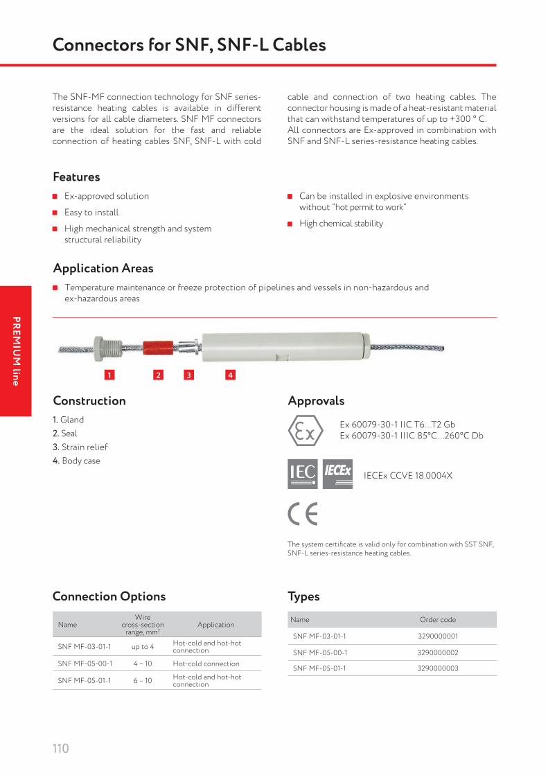
110
PREMIU
M line
Connectors for SNF, SNF-L Cables
Ex-approved solution
Easy to install
High mechanical strength and system structural reliability
Can be installed in explosive environments without “hot permit to work”
High chemical stability
Temperature maintenance or freeze protection of pipelines and vessels in non-hazardous and ex-hazardous areas
The SNF-MF connection technology for SNF series-resistance heating cables is available in different versions for all cable diameters. SNF MF connectors are the ideal solution for the fast and reliable connection of heating cables SNF, SNF-L with cold
cable and connection of two heating cables. The connector housing is made of a heat-resistant material that can withstand temperatures of up to +300 ° C. All connectors are Ex-approved in combination with SNF and SNF-L series-resistance heating cables.
Features
Application Areas
Construction
1 2 3 4
1. Gland2. Seal3. Strain relief4. Body case
Approvals
Ex 60079-30-1 IIC T6. . .T2 GbEx 60079-30-1 IIIC 85°C. . .260°C Db
IECEx CCVE 18.0004X
The system certifi cate is valid only for combination with SST SNF, SNF-L series-resistance heating cables.
Connection Options
NameWire
cross-section range, mm2
Application
SNF MF-03-01-1 up to 4 Hot-cold and hot-hot connection
SNF MF-05-00-1 4 – 10 Hot-cold connection
SNF MF-05-01-1 6 – 10 Hot-cold and hot-hot connection
TypesName Order code
SNF MF-03-01-1 3290000001
SNF MF-05-00-1 3290000002
SNF MF-05-01-1 3290000003

111
PREM
IUM
line
Construction
Cable Entry Unit LEK/U
ApprovalsThis product is exempt from mandatory certifi cation
Delivery SetPart Qty1. Lock nut 12. Metal plate 13. Self-tapping screws 44. Connector body GW50416 15. Connector seal 16. Cable seal (2 types) 17. Washer 18. Connector head 1
1
27
8
3
5
6
4
TypesName Order code
Cable entry unit LEK/U 7090100300

112
PREMIU
M line
PВ
DescriptionSupport brackets are used in cases where it is not possible to reliably mount the junction box onto the surface of a nearby structure (supports, traverses, etc.) of the heated system.When specifying the bracket, the dimensions of the heated system, its operating parameters and the
ApprovalsThis product is exempt from mandatory certifi cation
Bracket PBIntended for mounting onto small-diameter pipelines (up to 54 mm). Compatible with JB2221-223-2XXX, JB2221-333-2XXX box models not supplied with UVK pipe installation support (MOIC cables boxes excluded).
Brackets
Quick and easy installation, does not require special tools
Increased structural strength and reliable fastening to the heated surface
Resistance to vibration and alternating stresses
High accuracy of surface interface
Optimum size and weight
Versatility and compatibility with all standard sizes of JB junction boxes
* To be ordered separately
DimensionsL×W×H, mm
Weight,kg/pc. Mount
331×158×39 0,73 Two straps PFS*
Material – galvanized steel.
types of permissible installation work should be taken into account.On pp. 112-115 product range of support brackets fully compatible with all types of SST junction boxes is shown.If you have questions concerning compatibility with other equipment, please contact the nearest offi ce of SST Group.
Features
TypesName Order code
Bracket PB 7090101000

113
PREM
IUM
line
PL.JB 0606-10
PL.JB 0606-20
Bracket PL.JB 0606-10Intended for mounting onto pipelines with thermal insulation up to 100 mm thick. Compatible with JB2221-223-2XXX, JB2221-333-2XXX box models not supplied with UVK pipe installation support, thermostat exTHERM-AT. The equipment is mounted horizontally.
Bracket PL.JB 0606-20Intended for mounting onto pipelines with thermal insulation up to 150 mm thick. Compatible with JB2221-223-2XXX, JB2221-333-2XXX box models not supplied with UVK pipe installation support, thermostat exTHERM-AT. The equipment is mounted vertically.
Bracket KP1Intended for mounting onto large diameter pipelines and tanks with thermal insulation up to 120 mm thick. Compatible with JB2221-223-2XXX, JB2221-333-2XXX box models not supplied with UVK pipe installation support (JB2221-333-2(X)22 excluded).
* To be ordered separately
DimensionsL×W×H, mm
Weight,kg/pc. Mount
158×158×103 0.54 Two straps PFS*. Fasteners included in the bracket kit.
Material – galvanized steel.
DimensionsL×W×H, mm
Weight,kg/pc. Mount
299×160×40 1.09 Two straps PFS*. Fasteners included in the bracket kit.
Material: plate – galvanized steel, channel – steel.
DimensionsL×W×H, mm
Weight,kg/pc. Mount
304×300×115 1.8 Weld
Material – steel.KP1
Accessories
Types
Types
Types
Name Order code
Bracket PL.JB 0606-10 7090101001
Name Order code
Bracket PL. JB 0606-20 7090101002
Name Order code
Bracket KP1 7090101003

114
PREMIU
M line
Bracket KP3Intended for mounting onto adjacent metal structures, large diameter pipelines and tanks with thermal insu-lation up to 120 mm thick. Compatible with JB2221-223-2XXX, JB2221-333-2XXX box models not supplied with UVK pipe installation support.
Adapter bracket KP 102Intended for mounting the support stand UVK onto small diameter pipelines (less than 32 mm). Mounted onto the lower part of the support. One support requires one bracket kit KP 102 and KP 102-01.
Bracket KP101Intended for fastening the fastening tape to the heated surface. Mounted by welding to the heated surface.
DimensionsL×W×H, mm
Weight,kg/pc. Mount
152×158×128 0.6 Weld
Material – steel.
Designation DimensionsL×W×H, mm
Weight,kg/pc.
KP 102 39×18×15 0.0338
KP 102-01 39×22×15 0.0386
Material – steel.
Material – steel.
KP3
KP 102
KP101
Types
Types
Types
Name Order code
Bracket KP3 7090101004
Name Order code
Bracket KP101 7090101005
Name Order code
Adapter bracket KP 102 7090101006
Adapter bracket KP 102-01 7090101007
Brackets

115
PREM
IUM
line
К.JB10.YYY×ZZZ
Bracket К.JB10.YYY×ZZZIntended for mounting onto pipelines with longline electric heating system. Compatible with JB2221-544-21(60-65) boxes. Boxes are bolted to the plate PL.JB 1007-01.
Dimensions L×W×H, mm
Weight, kg/pc. Mount
299×160×40 1.09Belt clamp, bolt tightening. Fasteners included in the bracket kit.
Material: channel – steel.
Ordering InformationBracket K.JB10.YYY×ZZZ (YYY – pipe diameter in mm, ZZZ – model).
Product Range
Plate PL.JB 1007Intended for mounting onto pipelines with longline electric heating system. Compatible with JB2221-544-21(60-65) boxes. Mod. 01 for securing JB junction boxes to the bracket K.JB10.YYY×ZZZ. Mod. 02 for securing JB boxes is mounted onto the heated pipeline with two PFS straps.
Designation Dimensions L×W×H, mm
Weight, kg/pc.
PL.JB 1007-01 330×255×1.5 1.0
PL.JB 1007-02 300×255×1.5 0.76
Material – galvanized steel.
PL.JB 1007-01 PL.JB 1007-02
YYY ZZZ Order code057 050 7090101100057 064 7090101101057 090 7090101102057 100 7090101103089 070 7090101104089 100 7090101105108 050 7090101106108 060 7090101107108 100 7090101108114 060 7090101109114 070 7090101110134 000 7090101111159 050 7090101112159 100 7090101113168 090 7090101114219 050 7090101115219 100 7090101116219 120 7090101117234 000 7090101118273 000 7090101119273 075 7090101120273 100 7090101121280 000 7090101122280 100 7090101123
YYY ZZZ Order code308 000 7090101124314 000 7090101125315 000 7090101126325 050 7090101127325 100 7090101128331 100 7090101129334 000 7090101130348 000 7090101131355 000 7090101132355 100 7090101133400 000 7090101134419 000 7090101135422 000 7090101136426 080 7090101137450 000 7090101138500 000 7090101139556 000 7090101140556 150 7090101141560 000 7090101142573 000 7090101143630 100 7090101144720 090 70901011451020 110 70901011461220 000 7090101147
Accessories
TypesName Order code
Plate PL.JB 1007-01 7090101200
Plate PL.JB 1007-02 7090101201

116
PREMIU
M line
Self-Adhesive Aluminum Fastening Tape
ApplicationsFastening of heating cable onto flat surfaces, e.g. tanks, or onto a valve / pump body, padding of heating cables laid onto plastic pipes.
Technical DataLength 50 m
Width 50 mm
Permanent exposure temperature 110 °С
Recommended installation temperature Not lower than -5 °С
Adhesive material Acryl
Self-Adhesive Fastening Tape
ApplicationsFastening of heating cable to high temperature pipes.Compatible with all heating cable types.
Technical DataLength 33 m
Width 11 mm
Permanent exposure temperature 200 °С
Recommended installation temperature Not lower than -15 °С
Adhesive material Modified silicone
Tapes & Straps
Types
Types
Name Order code
Fastening tape FT/HTM 7090100000
Name Order code
Self-adhesive aluminum fastening tape 7090100001

117
PREM
IUM
line
Fastening Tape
ApprovalsThis product is exempt from mandatory certification.
ApplicationsFastening of cable to a tank.The fastening tape is fastened onto a tank using KP101 brackets or PFS straps.Coil lengh upon request.
25 mm
19 m
m
Accessories
Straps for Mounting Junction Box Brackets Onto a Pipe
ApprovalsThis product is exempt from mandatory certification.
The strap is intended for mounting junction box brackets directly onto the surface of a heated system (pipe, tank) and also for mounting heating sections based on MOIC cables with mineral insulation. The kit contents make it possible to assemble worm drive
straps of the required diameter in a short time without the use of special tools. With the help of the strap, parts can be mounted onto structures and equipment of any shape and size. Material – stainless steel.
Quick-action lock allows to mount the strap without the use of special tools, simplifying and speeding up the installation process
High strength and corrosion resistance Highly reliable installation Packaging convenient for storage and
transportation
Fasteners for PFS/30 StrapMetal lock with a screw for tightening the strap. Intended for reliably connecting worm drive straps of the required diameter. The fasteners are universal and can be used both for creating small-diameter straps and for mounting large-sized parts. Allow to connect the strap’s two loose ends. A small overlap is recom-mended when mounting the strap. Material – stainless steel.
Part name Length, m
Width, mm Type of band Weight,
kg Type of packaging Delivery kit, pcs.
PFS/3 3 12.7 Hose strap 0.3 Blister pack Strap – 1 pc. Fastening element – 8 pcs.
PFS/30 30 9 Hose strap 1.447 Plastic reel Strap – 1 pc. Fastening element – to be ordered separately / not included in the package.
Features
Types
Types
Name Order codeFastening tape 25, where 25 is the fastening spacing in mm. 7090100051
Name Order code
Fixing strap PFS/3 (3 m incl. 8 fixing elements) 7090100301
Fixing strap PFS/30 (30 m) 7090100302

118
PREMIU
M line
VeLL Heat Tracing System: VLL-A
VeLL heat tracing system is based on VLL-A and VLL-C special series-resistance heating cables. VLL-A is a series-resistant cable for extra long heating systems, approved for use in hazardous and non-hazardous areas when used as a part of SST designed VeLL Heat Tracing System. It has been designed for use in temperature maintenace or freeze protection applications of long and extra-long pipelines. VLL-A cable implements an aluminum heating wire, offering a cost-saving solution for a wide vareity of heat-tracing applications.Cables are installed in a linear way on the pipe surface. In case of pre-insulated pipeline fragments, the cable
is usually laid in conduits, which are on the pipe under thermal insulation.At the end of a heating segment cables are connected together in star (Y). At start of the segment voltage is applied between cables. Its value depends on the pipeline length and necessary power output.This is a specially designed conductor, resistant to high voltage up to 8 kV and thermal loads in operation up to +100 °C, also resistant to mechanical impact during installation or maintenance. The cable is supplied on drums with length, convenient for installation and connection on site.
Features
Construction
The only heat tracing system for heating extra-long pipelines up to 150 km without supply network
High operating temperature up to +100 °C High mechanical reliability
Electrical safety Connection technology and fasteners
come in unifi ed kits Easy and convenient installation
Temperature maintenace or freeze protection of extra-long pipelines in non-hazardous and ex-hazardous areas
Application Areas
Type 1 – up to 10 kV
1
2
34
5
1. Aluminum conductor core2. Conductor screen (semi-conductive layer)3. Insulation XLPE4. Insulation screen (semi-conductive layer)5. Copper wire braid covered with copper foil6. Special abrasion-resistant outer jacket
Type 2 – up to 3 kV
1
23
4
1. Aluminum conductor core2. Insulation XLPE3. Copper wire braid covered with copper foil4. Special abrasion-resistant outer jacket
6

119
PREM
IUM
line
Technical Data
MarkingExample: VLL-A-3.0-35-01
1. Cable type (VLL)2. Type of conductor (A – aluminum)3. Rated Voltage (3.0 kV)4. Conductor cross-section (35 mm2)5. Maximum continuous operating temperature (01 – 100 °C)
Approvals
IECEx CCVE 19.0010X3 4 521
VeLL Heat Tracing System
Product CharacteristicsRated voltage up to 8 000 VACMaximum continuous operating temperature (trace heater energized) up to +100 ˚С
Maximum intermittent temperature (trace heater de-energized) up to +120 ˚С
Ambient temperature range –60 … +55 °СMinimum installation temperature –40 °СConductive wire material Aluminium
Linear power output per one segment, connected in star
up to 30 W/m (average value, depends on application
TypeConduc-tor size, mm2
Dimensions (max OD), mm
Weight, kg/km
Minimum bend radius
Order code
VLL-A 25 25 18.2–22.6 601–814 15 outer diameters 3202000100
VLL-A 35 35 19.5–25 674–900 15 outer diameters 3202000101
VLL-A 50 50 21.3–25.9 703–932 15 outer diameters 3202000102
VLL-A 70 70 22.4–27.3 721–986 15 outer diameters 3202000103
* *
* Certification is underway

120
PREMIU
M line
VeLL Heat Tracing System: VLL-C
VLL-C is a series-resistance heating cable for extra-long oil & gas pipelines, approved for use in hazardous and non-hazardous areas. It has been designed for temperature maintenace or freeze protection of extra-long pipelines. VLL-C cable implements a copper heating wire, thus offers a perfect solution for a wide vareity of heat tracing applications.Cables are installed in a linear way on the pipe sur-face. In case of pre-insulated pipeline fragments, the cable is usually laid in conduits, which are on the pipe under thermal insulation.
At the end of a heating segment cables are connected together in star (Y). At start of the segment voltage is applied between cables. Its value depends on the pipeline length and necessary power output.This is a specially designed conductor, resistant to high voltage up to 8 kV and thermal loads in operation up to +200 °C, also resistant to mechanical impact during installation or maintenance. The cable supplied on drums with length, convenient for installation and connection on site.
Features
Construction
The only heat tracing system for heating extra-long pipelines up to 150 km without supply network
High operating temperature up to +200 °C High mechanical reliability
Electrical safety Connection technology and fasteners
come in unifi ed kits Easy and convenient installation
Temperature maintenace or freeze protection of extra-long pipelines in non-hazardous and ex-hazardous areas
Application Areas
Type 1 – up to 10 kV
12
34
5
1. Copper conductor core2. Conductor screen (semi-conductive layer)3. Insulation XLPE4. Insulation screen (semi-conductive layer)5. Copper wire braid covered with copper foil6. Special abrasion-resistant outer jacket
Type 2 – up to 3 kV
1
23
4
1. Copper conductor core2. Insulation XLPE3. Copper wire braid covered with copper foil4. Special abrasion-resistant outer jacket
6

121
PREM
IUM
line
Technical Data
Approvals
IECEx CCVE 19.0010X
MarkingExample: VLL-C-3.0-20-01
1. Cable type (VLL)2. Type of conductor (C – copper)3. Rated Voltage (3.0 kV)4. Conductor cross-section (20 mm2)5. Maximum continuous operating temperature (01 – 100 °C)
3 4 521
VeLL Heat Tracing System
Product Characteristics
Rated voltage up to 8 000 VACMaximum continuous operating temperature (trace heater energized) up to +200 ˚С
Maximum intermittent temperature (trace heater de-energized) up to +250 ˚С
Ambient temperature range –60 … +55 °СMinimum installation temperature –40 °СConductive wire material Copper
Linear power output per one segment, connected in star
up to 30 W/m (average value, depends on application
TypeConduc-tor size, mm2
Dimensions (max OD), mm
Weight, kg/km
Minimum bend radius
Order code
VLL-C 10 10 16.8–21.1 554–760 15 outer diameters 3202000150
VLL-C 15 15 18.2–22.6 601–814 15 outer diameters 3202000151
VLL-C 20 20 19.5–25 644–900 15 outer diameters 3202000152
VLL-C 30 30 22.4–26.6 739–958 15 outer diameters 3202000153
VLL-C 40 40 25.4–28.3 838–1019 15 outer diameters 3202000154
* *
* Certification is underway

122
PREMIU
M line
Heating of pipelines up to 60 km without supply network
High operating temperatures Electrical safety High mechanical strength of the heating system Approved for explosive areas
1. High-voltage line2. Control power station (CPS)3. IR-heater4. IR-conductor5. Thermal insulation6. Heated pipeline
PurposeHeat tracing system IRHS-15000 based on skin-effect is intended for maintaining pipeline temperature, pre-venting freezing, and start-up heating of long pipe-lines. The system supports underground, overground, underwater installation, including explosive areas.It is the only system capable of heating pipelines up to 60 km long (without an auxiliary network). This heating system can be used to heat pipelines of any length with an auxiliary power supply network.
Operating principleThe heating element of IRHS-15000 is composed of an inductive-resistive heater (IR heater) with an external diameter of 15–60 mm and a wall thickness of at least 3.0 mm and a built-in insulated inductive-resistive copper conductor (IR conductor) with a cross section of 8–40 mm2. At the terminal end of the heating segment, the IR-conductor is electrically connected to the IR-heater, and alternating voltage is supplied at the start end of the segment between the IR-heater and the IR-conductor. The voltage is determined based on the desired heat generation and the length of the heating section.IR-conductor and IR-heater currents fl ow in opposite directions, resulting in a surface effect and proximity effect in the system. As a result, the current in the IR-heater fl ows along the inner layer near the inner surface of the IR-heater and there is no voltage on the IR-heater. The IR-conductor is non-magnetic (copper), there is no noticeable surface effect in it, and the alternating current fl ows through the entire cross section of the IR-conductor.The main heat generating element in the skin-effect system is the IR-heater, accounting for up to 80% of the system’s output.
5
6
3
4
1
2
Structural design
IR-heaterLow-carbon steel pipe with a diameter of 15-60 mm, wall thickness 3-4 mm
IR-conductor
Special conductor is resistant to high voltage (up to (5 kV), thermal loads (up to +260 °C), and mechanical loads during installation
IRPK, IRSK, IRKK, IRS, KTP
Connection, power supply, terminal boxes, glands, control power station
Heat Tracing System Based on Skin-Effect
Technical DataHeated pipeline length up to 30 km without
an auxiliary network
Heating system output up to 170 W/mMaximum operating temperature +240 °СMaximum permissible temperatureа (without load) +260 °С
Ambient temperature range -60…+70 °СVoltage on the heating element up to 5 kVCross-section of the IR conductor up to 40 mm2
Approvals№ ОГН4.RU.1304.В00238IECEx CCVE 18.0002X DEKRA 18ATEX0033 X
Features and Application Areas

123
PREM
IUM
line
Control and Power Supply Diagram
To power the load, transformer-capacitor converters are used, which consist of a load balancer and a special-purpose transformer. It allows to connect a high single-phase load (the skin system heater) to a three-phase supply, and there is no current misalign-ment on the power supply side.
The control system monitors ambient air temperature, IR-heater temperature, heated pipeline temperature, load current and load voltage. The control system allows to remotely control the heating and monitor all the vital parameters.
Heat Tracing System Based on Skin-Effect
Temperature sensor, airCONTROL POWER STATION
Control cabinet
Power cabinet
Temperature sensor, pipeline
IR-heater temperature sensor
Special-purpose transformer
Load balancer
Power supply line
Heat GenerationSpecific heat generation of a single element, W/m
Maximum length of heated section, km
Heater diameter
42×332×325×3
Cross-section of the current-carrying conductor
40 mm2
20 mm2
10 mm2
IR-heater
IR-conductor
Heat-conducting paste SILARM
Heat flux
Safety of the system is provided by the surface effect causing the current to follow the internal surface of the IR-heater. The external surface potential is zero.Heat transfer from the skin system to the pipeline is supported by the tight contact and the use of the heat-conducting paste SILARM.
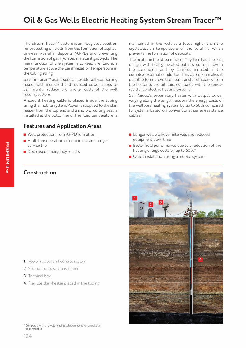
124
PREMIU
M line
132
4
Oil & Gas Wells Electric Heating System Stream Tracer™
Well protection from ARPD formation Fault-free operation of equipment and longer
service life Decreased emergency repairs
The Stream Tracer™ system is an integrated solution for protecting oil wells from the formation of asphal-tine-resin-paraffi n deposits (ARPD) and preventing the formation of gas hydrates in natural gas wells. The main function of the system is to keep the fl uid at a temperature above the paraffi ni zation temperature in the tubing string.Stream Tracer™ uses a special fl exible self-supporting heater with increased and reduced power zones to signifi cantly reduce the energy costs of the well heating system.A special heating cable is placed inside the tubing using the mobile system. Power is supplied to the skin heater from the top end and a short-circuiting seal is installed at the bottom end. The fl uid temperature is
1. Power supply and control system
2. Special-purpose transformer
3. Terminal box
4. Flexible skin-heater placed in the tubing
* Compared with the well heating solution based on a resistive heating cable
maintained in the well at a level higher than the crystallization temperature of the paraffi ns, which prevents the formation of deposits.The heater in the Stream Tracer™ system has a coaxial design, with heat generated both by current fl ow in the conductors and by currents induced in the complex external conductor. This approach makes it possible to improve the heat transfer effi ciency from the heater to the oil fl uid, compared with the series-resistance electric heating systems.SST Group’s proprietary heater with output power varying along the length reduces the energy costs of the wellbore heating system by up to 50% compared to systems based on conventional series-resistance cables.
Features and Application Areas Longer well workover intervals and reduced
equipment downtime Better fi eld performance due to a reduction of the
heating energy costs by up to 50%* Quick installation using a mobile system
Construction

125
PREM
IUM
line
* A heater 3 km long is under development
The heater remains operational at an external pressure of up to 150 atm and a temperature of up to +70 °C.The heater remains operational after 100 bends at a radius of 400 mm (at temperatures above 0 ˚C).
Technical DataPower supply voltage up to 1 kVLinear power 50 W/mHeater length 1.5 km*Minimum temperature of installation -25 °C
Minimum bending radius 400 mm
Crushing force up to 12 kN (at a running speed of 0.25 m/sec)
Tensile force up to 28 kNChemical resistance to petroleum products high
Energy Efficiency
The design and manufacturing technology offered by SST Group allows adjusting the linear power of heat generation in individual sections of the heater (the orange line in the figure), giving an advantage over the series-resistance heaters (the red line in the figure).
Temperature, °C
Dep
th, m
0 10 20 30 40
0
200
400
600
800
1000
1200
1400
1600
Energy costs of the system
Waxing point
Energy savings up to 50%
Liquid without heating
ARPD forming temperature
Liquid, conventional resistive heating
Liquid, Stream Tracer™ heating
Energy efficiency of Stream Tracer™ compared to a series-resistance cable
Oil & Gas Wells Electric Heating System Stream Tracer™

126
PREMIU
M line
IMPORTANT!1. To avoid overheating, the cable should not overlap
or be laid in insuffi ciently spaced stretches.2. Installation instructions must be strictly followed.
Power Supply SystemThe electric heating system is connected to either a source of power (a dedicated step-up transformer with a supply voltage higher than 380 V) or a three-phase grid via a power management system.The power supply output should match to the power intake of the electric heating system. The included cold-start system helps to reduce starting currents.
Longline Heat Tracing SystemSST Energomontazh, part of SST Group, not only offers LLS heating cables forming a part of the electric heating system, but also designs, manufactures and carries out the installation of integrated systems adapted to the specifi c conditions on the customer’s site. Scope of supply includes a source of power (if the voltage is other than 380 V), a power management and temperature control system, circuit integrity monitoring / control equipment, power connection boxes, maintenance boxes, connection fi ttings and other accessories designed for installation as part of your heat tracing system.
ApplicationsLLS is a three-phase series-resistance heating cable used to prevent freezing or maintain the temperature in pipelines of intermediate length (up to 4 km) in safe and explosive areas.A typical application is maintaining the temperature in overground or underground oil and gas pipelines, protecting water lines from freezing.
Longline Heat Tracing System
Heated section length up to 4 km
High heat generation up to 40 W/m
High effi ciency, large heat transfer surface area and fl exibility
Full set of control tools and accessories
Single connection to the power source to minimize the cost of the cable system
Easy installation
1 2 3 4
1. Heating cores of copper wire2. Silicone rubber insulation3. Tinned copper wire armor4. Silicone rubber jacket
SST longline heat tracing system is based on LLS heating cable which is composed of three parallel heating cores of copper wire insulated by silicone rubber, covered by a tinned copper wire armor and a silicone rubber jacket.The heating cores are sized to support the desired heat generation by the required circuit length. Heating cables are connected directly to a three-phase power supply or, if required, to a step-up transformer.The large heat transfer surface of the fl at heating cable reduces operating temperature compared to similar heating cables with a cylindrical conductor design, thereby improving the effi ciency, safety and service life of the
heating cable. Using as an insulator silicone rubber capable of retaining its electrical and mechanical proper ties over a broad temperature range makes it possible to achieve a heat generation level of up to 40 W/m.LLS cables can be arranged in a straight line or spirally on a pipe. On pre-insulated pipelines the cables are usually routed via conduits mounted on the pipe under the thermal insulation.The heating cable is delivered in convenient lengths for serial connection on site or as ready-made heating sections. The system minimizes the number of power source connections and thus reduces the required investment into power supply networks.
Features and Application Areas
Construction

127
PREM
IUM
line
Power supply
CC
DTV
DTK
DTK
DTT
DTT
Transformer T1
Power cable
Power connec-tion box
Maintenance box
Terminal box
Terminal connector
Connector
Heating section
Terminal connector
Heated pipeline
Terminal connector
Terminal connector
Heating limit
Heating limit
Maximum Pipe / System TemperatureSurface temperature of the heating cable must not exceed maximum temperature that its structural materials can withstand or the temperature class of the respective area (if installed in a potentially explosive area). This is achieved by limiting the heat generation of the heating cable depending on the temperature of the pipe or heated system to a safe level as part of the design or by means of a temperature control system. For the most unfavorable heat exchange conditions, the pipleline temperature must be limited to the following threshold values:
Technical Data
Maximum temperature of the heated system, °СNominal heat
generation, heating cable,
W/m
LocationExplosive
SafeТ6 Т5 Т4 Т3 Т2 Т1
5 55 70 100 100 100 100 10010 50 65 95 95 95 95 9520 30 45 75 75 75 75 7525 20 35 70 70 70 70 7030 10 25 55 55 55 55 5535 – 15 45 45 45 45 4540 – – 30 30 30 30 30
Maximum operating temperature +130 °СMaximum permissible temperature without load +180 °С
Ambient temperature range -60…+55 °СMinimum installation temperature -60 °С
Power supply three-phase up to 900 V depending on version for specific application
Heat generation up to 40 W/m depending on version for specific application
Ех marking 1Ех е IIС Т3 Gb XDegree of external protection GOST 14254-96 IP67
Heating core cross section 1.5 mm2, 3.0 mm2, 6.0 mm2
Please note that the manufacturer can change the dimensions of the cores to provide the required heat generation (W/m) at a given circuit length.
DimensionsType Nominal size,
mmMinimum bending radius, mm
LLS 3×1.5 14.9×7.8 40LLS 3×3.0 16.9×8.5 45LLS 3×6.0 19.6×9.4 50
Longline Heat Tracing System
Model Installation Diagram
Accessories (to be ordered separately)Junction boxes, series JB2221-544-2X(60-64) (see pp. 84-85).LLS-SK kit is a connection for splicing LLS heating cables on the site.LLS-TK kit is a connection for the heating cable LLS 3x6.0, including installation wire connected to a power supply, maintenance or terminal box (factory-installed).
TypesName Order codeLLS 3x1.5 3202000000LLS 3x3.0 3202000001LLS 3x6.0 3202000002LLS-SK 3299004000LLS-TK 3299004001

Questionnaires
128
Heating of PipelinesPlease fill out and send us this questionnaire containing the parameters required to design the electric heating system. We will respond with a detailed quote.
2
4
5
678910111213
15
3
14
1
QUESTIONNAIRE
Customer*
Company
Name Surname
Phone
Name
Location*
Available design documentation for heated object Yes No
Installer
Responsible representative
Thermotechnical stage (TTS) (installation drawings and cabinets one-line diagrams)
Freeze protection
Temperature maintenance
Anti-condensate heating
Heating-up Time of heating hours Initial temperature °C
°C, Required pipe temperature*
°C, Minimum ambient temperature
°C, Maximum ambient temperature
°C, Maximum steam temperature in case an object steaming is stipulated
°C, Standard process-oriented temperature* (Product temperature under standard operational conditions)
°C, Maximum process-oriented temperature* (The highest process-oriented temperature the product may occasionally attain)
°C, Maximum allowed product temperature* (The product highest temperature having no adverse effect on the product properties)
°C, Minimum activation temperature* (The lowest temperature, which enables activation of the heating system)
Normal (water, household wastewater)
Open air Undeground Depth m Soil
Indoors
External Internal
Mineral wool Preinsulated pipes
Foamed rubber Other, heat conductivity coefficient
Onsite Preinsulated pipes
Safe Explosion hazardous
Carbon steel Stainless steel
Plastic
PipelinePipeline name
Pipeline diameter
Heat insulation thickness, mm
Pipe length, m
Quantity of valves, pcs
Quantity of flanges, pcs
Quantity of pipe supports, pcs
Pumped product
Product density, kg/m3
Product heat capacity, J/(kg•°C)
Other, heat conductivity coefficient
W/m•°C
W/m•°C
Corrosive (oil, lube oils, industrial wastes)
Electrotechnical stage (ETS) (electric networks laying diagrams, cable record)
Automation (ACS - automated control systems) (a possibility of centralized control and data transfer to the higher level)
Thermal insulation (TI) (equipment thermal insulation drawings, list of equipment to be installed)
Phone
Site object*
Type of design works*
Purpose of the system
Temperature conditions
Steaming*
Environment
Cabling
Heat insulation type*
Heat insulationinstallationZoneclassification
Pipe material*
Parameters of pipeline*
Further information
* Required field (mandatory for completion)
Date*
Pipeline location*
QUESTIONNAIRE

Que
stio
nnai
res
129
Heating of TanksPlease fill out and send us this questionnaire containing the parameters required to design the electric heating system. We will respond with a detailed quote.
1
2
4
5
6
7
8
9
12
13
14
3
1110
QUESTIONNAIRE
Customer*
Company
Name Surname
Phone
Name
Location*
Available design documentation for heated object
Installer
Responsible representative
Thermotechnical stage (TTS) (installation drawings and cabinets one-line diagrams)
Freeze protection
Temperature maintenance
Anti-condensate heating
Heating-up Time of heating hours Initial temperature °C
°C, Required vessel temperature*
°C, Minimum ambient temperature
°C, Maximum ambient temperature
°C, Maximum steam temperature in case an object steaming is provided
°C, Standard process temperature* (Product temperature under standard operational conditions)
°C, Maximum process temperature* (The highest temperature the vessel may occasionally attain)
°C, Maximum allowed product temperature* (The product highest temperature having no adverse effect on the product properties)
°C, Minimum activation temperature* (The lowest temperature, which enables activation of the heating system)
Open air On the soil
Indoors On supports, their design:
External
Internal
m
m
Distance to heating control point
Distance to power supply point
Mineral wool (mats) Thickness mm
Others, heat-conductivity factor
Safe Explosion hazardous (zone classification)
Carbon steel Stainless steel
Plastic
Horizontal Vertical Fullness coefficient
Diameter
Fittings and hatches:
Type of cover: Flat
Spherical
Conic
Cover height m
mm mmHeight mmWalls thickness
Name*
Density kg/m3
Viscosity at a temperature °Ckg/m•s
Heat capacity J/kg•°C
m3/hDischarge Continuous Cyclic
Other, heat conductivity coefficient
W/m•°C
W/m•°C
Electrotechnical stage (ETS) (electric networks laying diagrams, cable record)
Automation (ACS - automated control systems) (a possibility of centralized control and data transfer to the higher level)
Thermal insulation (TI) (equipment thermal insulation drawings, list of equipment to be installed)
Phone
Site object*
Type of design works*
Purpose ofthe system*
Temperature conditions
Steaming
Cabling*
Heat insulation type*
Zoneclassification
Vessel material*
Parameters of the vessel*
Parameters of the product
Further information
* Required field (mandatory for completion)
Date*
Object location*
QUESTIONNAIRE

Questionnaires
130
Heat Tracing System IRHS-15000 Based on Skin-Effect for Pipelines Please fill out and send us this questionnaire containing the parameters required to design the electric heating system. We will respond with a detailed quote.
2
5
6
8
1
3
4
7
1011
12
9
13
QUESTIONNAIRE (INCLUDES ATTACHMENT FOR PACKAGE TRANSFORMER SUBSTATION DESIGN)
Customer*
Company
Name Surname
Phone
Name
Location*
Available design documentation for heated object Yes No
Installer
Responsible representative
Thermotechnical stage (TTS) (installation drawings and package transformer substation (PTS) diagrams)
Freeze protection
Temperature maintenance
Open air
Subsea
Underground
In plant conditions Onsite
Laying depth
With pipeline laying depth of over 0.7m from the soil surface, specify the average temperature of the coldest month °С
m Soil
Anti-condensate heating
Heating-up Time of heating hours Initial temperature °C
°C, Required pipeline temperature*
Minimum ambient temperature minus °C, maximum ambient temperature °C
°C, Standard process temperature* (Product temperature under standard operational conditions)
°C, Maximum process temperature* (The highest temperature the vessel may occasionally attain)
°C, Maximum allowed product temperature* (The product highest temperature having no adverse effect on the product properties)
°C, Minimum activation temperature* (The lowest temperature, which enables activation of the heating system)
Mineral wool Foamed polyurethane
Foamed rubber
From one end of heated area Others
From both ends mDistance from power supply point to the beginning of heated area*
Other, heat conductivity coefficient
Safe Explosion hazardous (area classification)
Carbon steel Stainless steel
Plastic
Pipeline
Pipeline name
Pipe outer diameter, mm
Pipe wall thickness, mm
Heat insulation thickness, mm
Pipe length, m
Number of valves, pcs
Number of flanges, pcs
Number of pipe supports, pcs
More detailed further information can be entered in the Attachment
Other, heat conductivity coefficient
W/m•°C
W/m•°C
Electrotechnical stage (ETS) (electric networks laying diagrams, cable record)
Automation (ACS – automated control systems) (a possibility of centralized control and data transfer to the higher level)
Thermal insulation (TI) (equipment thermal insulation drawings, list of equipment to be installed)
Phone
Site object*
Type of design works*
Purpose of system
Temperature conditions
Pipeline location*
Heat insulation type*
Supply points location*
Heat insulationinstallation*
Zoneclassification
Pipe material*
Parameters of pipelines*
Further information
* Required field (mandatory for completion) Please make sure to fill in the Attachment!
Date*
QUESTIONNAIRE INCLUDES ATTACHMENT FOR PACKAGE TRANSFORMER SUBSTATION DESIGN

Que
stio
nnai
res
131
Heat Tracing System IRHS-15000 Based on Skin-Effect for Pipelines Please fill out and send us this questionnaire containing the parameters required to design the electric heating system. We will respond with a detailed quote.
2
1
3
4
5
6
7
8
9
10
11
12
13
14
15
ATTACHMENT TO THE QUESTIONNAIRE
Customer*
Company
Name Surname
Phone
Name
Location*
Available design documentation for heated pipeline Yes No
Installer
Responsible representative
Kiosk type without heat insulation and heating
Kiosk type with heat insulation and heating
Cable
Aerial
On soil
On supports
Others
Phone
Site object*
PTS design
Supply lead
Installation
Indication
Fire extinguisher
Automatic
Others:
Fire fighting system
Natural draft
Forced draft
Air conditioner
Others:
Ventilation system
Yes
No Others:Remote control
Signaling
Control
Monitoring
Others:Telemetry
Horizontal
VerticalOthers:Earthing
Yes
NoOthers:
Energyaccounting
Oil filled
Dry
Transformer type
Relay module
Electronic module
Diesel generator
Power line
Others
Supply voltage
Frequency
Number of phases
V
Hz
Protection type
System’s power supply parameters*
Further information
* Required field (mandatory for completion) Please make sure to fill in the Questionnaire!
Date*
ATTACHMENT TO THE QUESTIONNAIRE

Questionnaires
132
Preventing Wax Deposits in Oil & Gas Wells: Stream Tracer™
Que
stio
nnai
re
2
3
5
1
4
QUESTIONNAIRE
Generalinformation*
Temperaturesdistributionby the depth
Stratum �uiddetails
Well operationmode
Well site’sdata
6Data forevaluation ofthe heating
Company
Well ID
Explosive area borders during maintenance mode andnormal operation mode
Power supply available for heating system (voltage, power)
Mode of operation
Well depth m The diameter of the production string mm
Diameter of PSP (Pressure-compressor pipe) mm Depth of suspension of PSP m
Oil layer temperature
Water percentage
Static level
Oil debit
Dynamic level
The maximum depth of the heavy oil’s deposits
°С
%
The gas factor m3/ton
m
Well maintenance schedule
PSP cleaning method
times per year
The period between cleaning of SPS from heavy oils times per year
m
m
Fluid temperature at wellhead °С
Fluid debit (with clean PSP) m3 /day
%
Data provided by(name, position)*
Phone, е-mail*
Permafrost depth m
Average temperature of the coldest month °С °С
°С
Maximum temperature of the warmest month
OIL WELL TECHNICAL QUESTIONNAIREHeating system parameters evaluation formfor installation of electrical heating system
SST GmbH | i_Park Tauberfranken 18 | 97922 Lauda-Königshofenphone: +49 9343/98091-00 | fax: +49 9343/98091-01e-mail: [email protected] | web: www.sst-international.com
* Required �eld (mandatory for completion).
Please fill out and send us this questionnaire containing the parameters required to design the electric heating system. We will respond with a detailed quote.
QUESTIONNAIRE
N
mm
pcs pcs pcs
mm mm
FOR JUNCTION BOXES
Enclosure material
Dimensions
Temperature class
Explosion protectionHousing1
Terminalblock2
L N
A
A
B
B
C
C
D
D
PE
Cableglands3
Options andaccessories4
5
6
7
IP
Operating temperature
Connection wire
Nominal current
Wire section
Quantity
Type of terminals
level required
Length mm × Width
plastic
“d” “ia”
stainless steelaluminium
“e” without explosion protection
IP 65
T4 T5 T6
°C°C
IP 67IP 66 IP 68
Т from to
mm × Depth mm
screw spring
Installation side
Cable gland type & size
External Ø of cable, mm
Cable gland material
Mechanical cableprotection
Quantity, pcs
Cable type
Internal Ø of cable, mm
Anticondensation inner coating Protective hood External earthing lug
Drain unit LED-light indicatiorPipe installation support
Terminals installation on 15 mm DIN-rail Terminal bridges per customer specification(i.a. at producer's option)
Design based on model-analogue Model
Quantity of junction boxes pcs
Phone E-mail
Date of completion
Company Contact person
Additional information
Contact information
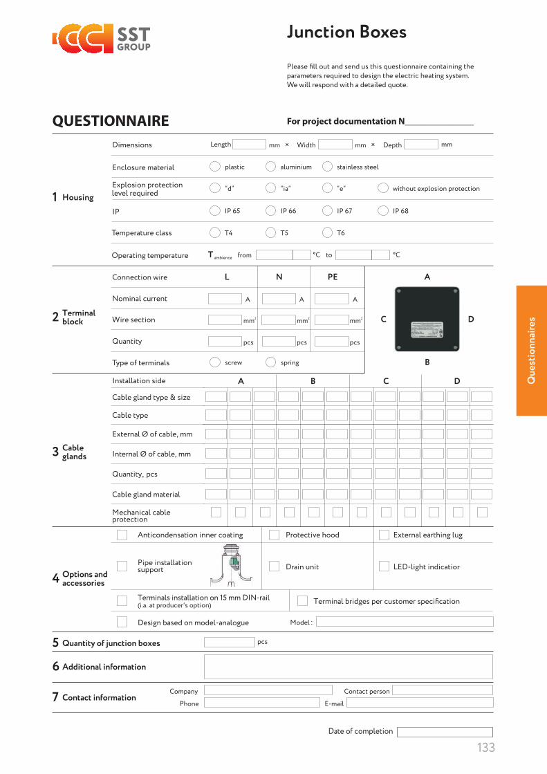
Que
stio
nnai
res
133
Please fi ll out and send us this questionnaire containing the parameters required to design the electric heating system. We will respond with a detailed quote.
N
mm
pcs pcs pcs
mm mm
FOR JUNCTION BOXES
Enclosure material
Dimensions
Temperature class
Explosion protectionHousing1
Terminalblock2
L N
A
A
B
B
C
C
D
D
PE
Cableglands3
Options andaccessories4
5
6
7
IP
Operating temperature
Connection wire
Nominal current
Wire section
Quantity
Type of terminals
level required
Length mm × Width
plastic
“d” “ia”
stainless steelaluminium
“e” without explosion protection
IP 65
T4 T5 T6
°C°C
IP 67IP 66 IP 68
Т from to
mm × Depth mm
screw spring
Installation side
Cable gland type & size
External Ø of cable, mm
Cable gland material
Mechanical cableprotection
Quantity, pcs
Cable type
Internal Ø of cable, mm
Anticondensation inner coating Protective hood External earthing lug
Drain unit LED-light indicatiorPipe installation support
Terminals installation on 15 mm DIN-rail Terminal bridges per customer specification(i.a. at producer's option)
Design based on model-analogue Model
Quantity of junction boxes pcs
Phone E-mail
Date of completion
Company Contact person
Additional information
Contact information
Junction Boxes
QUESTIONNAIRE For project documentation N_______________

Notes

Notes

Notes


Europe
Switzerland+41 245345900infoch@sst-international .com
Germany+49 9343 98091-00 info@sst-international .com
HEAT TRACING COMPONENTS & SOLUTIONS
Heat-Tracing-Components- and-Solutions-SE-011119
© 1991–2019 SST Group
www .gammaswiss .com
part of
Middle East & India
United Arab Emirates+97 1544441205, +97 1569712266sales-me@sst-international .com
India+91 9810379128sales@sstthermal .com
Russia & CIS
Russia+ 7 495 627-72-55info@sst-em .ru
Ukraine+38 044 499-11-22market@teploluxe .ua