se amp cad - glassware ver.1.pdf · now with se amp cad, you can point and click to a new ......
TRANSCRIPT

GlassWare
SE Amp CAD
SE Amp CAD™
Single-Ended Amplifier Computer Aided Design Program for Windows Version 1
SE Amp CAD™ is the new Windows program that helps you design, understand and modify single-ended amplifier output stages. Prior to the arrival of this program, designing a single-ended amplifier required breaking out old tube manuals, textbooks, ruler, calculator, and lots of scratch paper. Now with SE Amp CAD, you can point and click to a new output stage configuration in minutes. SE Amp CAD is a virtual workbench for single-ended output stage design. True Curves™ is the name of the new mathematical model used in SE Amp CAD. True Curves knows how a 300B or an 845 really bends: how the plate current varies with changes in grid to cathode voltage versus changes in plate voltages. With the True Curves tube model in SE Amp CAD you can quickly and easily model, evaluate, and understand a tube single-ended output stage. SE Amp CAD holds 30 tube (triode and triode-connected pentodes) models and over 100 output transformer profiles. The output data results, the output circuit schematic, the tube's plate curves (grid voltage, plate voltage, plate current, rp, mu, Gm), the input signal and the resulting output signal —all are displayed interactively by SE Amp CAD.
File Tools Scenarios Results Schematic Curves Wave Forms Options HelpCircuit SetupTube P.T.
One Electron UBT 2
Vp= 449. v Vg= -38.1 v Ip= 75.0 ma P= 33.7 w gm= 5.17 ma/v mu= 7.83 rp= 1.52k
Calculate Results0 20 100 v 200 v 300 v 400 v 500 v 600 v 700 v 800 v 900 v 1 kv
Transfer Func. Plate Lines Imax Wp Vmax Setup BMP
150 mA
120 mA
90 mA
60 mA
30 mA
5 mA
50
456
734
455
4800
35Vin
mA
B+
Rk
Rt
Rl
807
Transformer
SE Amp CAD Virtual Oscilloscope
Live Curves
Live Schematic Updates
Logical Result Grouping
Large Tube Model Library
100+ Transformer ModelsMinimum Requirements: 32 MB RAM Windows 95/98/NT/Me/2000 CD ROM Drive 6 MB free hard disk space Super VGA (256 colors) 100 MHz Pentium or better CPU
All Rights Reserved. Copyright ©1998-2001 GlassWare.
PO Box 231 Fenton MI 48430
lass areGAUDIO DESIGN SOFTWARE
Ww w w . g l a s s - w a r e . c o m

GlassWare
SE Amp CAD
This program and user guide are intended for amusement and instructional purposes—solely. We at GlassWare assume no responsibility for the use of any of the information provided. Much of what is detailed in the User Guide and program refers to potentially lethal voltages. Always let an electronically trained person review what you are planning on building and what you have built.
© GlassWare 1998-2001
All rights reserved. No part of this publication may be re-produced, transmitted, stored in a retrieval system, or translated into any language by any means without the permission of GlassWare.
True Curves and SE Amp CAD are trademarks of GlassWare. Windows is a registered trademark of Microsoft. Other products mentioned are trademarks or registered trademarks of their respective companies.
GlassWare™ PO Box 231
Fenton MI 48430
USA
www.glass-ware.com
E-mail: [email protected]
DISCLAIMER

GlassWare
SE Amp CAD
INTRODUCTION
Welcome to SE Amp CAD, the Windows program that helps you design, understand and modify single-ended amplifiers. Prior to the arrival of this program, only three ways realistically presented themselves to the designing of a single-ended ampli-fier. The first was to break out old tube manuals (yes, “old” and “tube manual” together is redundant), textbooks, ruler, calcula-tor, and lots of scratch paper. The second to was just break out the soldering iron and build and test and change components and test until your design was vindicated or proven undesirable. The last way was both the most high tech and the least realiz-able for most amateur constructors—namely, learn to use one of the many variations of SPICE and try to model the output tube and transformer as well as you could to get a fair idea of how the proposed amplifier would work in practice.
Admittedly, this last approach still holds the greatest potential for revealing the unique behavior of a specific tube working with a specific transformer in a time domain analysis; unfortu-nately, it also requires the biggest investment of time and intel-lectual energy. Furthermore, as no one yet has come up with a SPICE model of the triode as accurate as the one used in SE Amp CAD, let alone a program specific to SE amplifier design, SE Amp CAD is the quickest, easiest way to model, evaluate, and understand a tube SE output stage.
Why does SE Amp Cad just cover tube single-ended output stages and not transistor or push-pull stages? And why not input stages while you’re at it? Paradoxically, the answer is the same as why a home finance budget program doesn't do Macaulay's duration of a cash flow stream: the more universal a program, the less useful it will be to most people. SE Amp CAD’s only concern is triode based (or triode connected pentodes) single-ended tube output stages and is only useful to those who want to understand and design single-ended amplifiers, but it is very useful to them indeed.
INSTALLATION The SE Amp CAD program cannot be run from the diskette; it must be installed to a hard drive. Furthermore, the installation program and the program itself must be run under Windows 3.1 or better. A 1.44 Mb floppy drive and at least 2 megabytes worth of free space are required to install SE Amp CAD.
Start by placing the floppy disk into its drive, either A or B; then, under the “File” heading of Program Manager in Win-dows 3.1 or at the pressing of the “Start” button in Windows 95, select RUN. From there press the “Browse” button to bring up the drive that contains the SE Amp CAD diskette. Once that drive is highlighted, select “Install.exe” Press the “OK” button and the installation program will come up.
The installation program will need to know where you wish to copy SE Amp CAD on your hard drive, the default being a di-rectory named “Audio.” It will further need to know if you wish to make a program group to hold the SE Amp CAD icon.
TWO POINTS
ONE.
This program took lots of work and sweat and sacrifice to create. It is very doubtful that the time that went into creat-ing this program will ever be compensated by its sales. The market for tube audio software is microscopic compared to vir-tually any other. It was written out of a love for vacuum tube circuits. Consequently, please do not give copies of this pro-gram to your friends. Simply put: there are not that many audiophiles left; you are one of them as are we at GlassWare; in order to make a go of writing audio-related software there must be honesty and consideration amongst ourselves.
TWO.
If you find something missing or wrong or troublesome, take notes. Given enough interest, SE Amp CAD will evolve and develop into something better in the future. We have several ideas about what might be added to version two. You, the user, know what would really excite you and, unlike so many pro-grams that are written only to fill a marketing segment, we at GlassWare believe in and design and build and use tube equip-ment exclusively. We, as much as anyone else, want to see SE Amp CAD evolve into a better program that we can use our-selves. With your help, it will be even better still. So, please, let us know what you think. If you have an improvement in mind for SE Amp CAD, let us know what it is. A letter, post card or e-mail would be great.

GlassWare
SE Amp CAD
HOW A TRIODE WORKS A vacuum tube is a multi-element electronic device that allows for the conduction of current in only one direction: from cath-ode to anode (plate). Diodes, triodes, tetrodes, and pentodes are all examples of vacuum tubes. They differ in the number of in-ternal elements.
First, The Diode The diode contains only a cathode and an anode. The cathode and anode are similar in that they are simple conductive metal structures, but the cathode differs from the anode in that the cathode is coated with a substance that when heated emits elec-trons. The necessary heat can be derived either indirectly, by wrapping the cathode around a heating element that does not differ radically from the heater element in a toaster, or directly, by passing a strong cur-rent through the cathode itself. The anode can only receive electrons, as only the cathode can emit electrons. And the anode can only receive electrons from the cath-ode when it is more positive than the cathode, as electrical current only flows from negative to positive. This one-way function of the diode results in there being only two useful means to control or adjust the amount of current flowing through the diode: 1) reverse the diode's connections to the power supply or 2) vary the voltage potential across the diode.
This inflexibility of adjusting the current flow restricts the di-ode to the power supply portion of a tube audio amplifier. Here the single direction of current flow allows the power supply to convert the alternating current flow of the wall receptacle into pulsating direct current conductions, whose energy is then smoothed and stored as the direct current B+ voltage by the ca-pacitors and chokes of the power supply.
The Grid The triode adds a current control element called the grid. Physi-cally, the grid is both an electrically conductive and an electri-cally porous structure that shrouds the cathode. Like the cath-ode in the diode, the triode's cathode is the only element that emits electrons. Like the diode, the triode can only conduct in one direction: from negative to positive, i.e. when the cathode is negative relative to the anode or, phrased differently, when the anode is more positive than the cathode. A triode is so much like a diode that a diode can be made from a triode whose grid
is allowed to float, i.e. is not con-nected to the rest of the circuit. But when the grid is connected to the rest of the circuit, the triode is born and the business of amplify-ing begins.
The grid not only surrounds the cathode, but is much closer to it than it is to the plate (anode). The
Clicking the outside (usually the right button for right-handed users) mouse button brings up the floating menu displayed to the right. This menu allows the user to quickly bring up the various dialog boxes and load and unload scenarios.
When a menu item is “grayed” it means that selection has al-ready been made, in this example that the circuit schematic is already in view. .
Click the “Schematic” menu item to bring up the output cir-cuit schematic display.
Click the “Wave Forms” menu item to bring up the oscilloscope like display of the output stage's handling of sine, square, and triangle waves.
Click the “Curves” menu item to bring up the output tube's plate and grid curves display.
Click the “Results” menu item to bring up the output circuit's AC and DC data display.
The hint line displayed in the black background changes to re-flect where the mouse is positioned over the SE Amp CAD Pro-gram.
MOVING ABOUT IN SE AMP
The static or idle current through each triode.
anode
cathode
curre
nt fl
ow
curre
nt fl
ow
+ +
__
anode
cathode
Vacuum Tube Diode Solid State Diode
anode
cathode
curr
ent
flo
w+
_
V acu um T u be T riode
grid
2

GlassWare
SE Amp CAD
HOW A TRIODE WORKS grid controls the current flow: when negatively charged relative to the cathode, the grid repels the electron stream that leaves the cathode; and, when positively charged, attracts the electron stream. The closer the grid is to the cathode, the more the grid can control the current flowing through the tube. Remember, electrons can only flow from negative to positive no matter what the device: transistor, MOSFET, zener diode, LED, fuse, resistor. Therefore, the grid's relative voltage charge to the cath-ode makes the grid either attractive or repellent to the flow of electrons from the cathode. Once the grid was born, so was the means to controlling the flow of current, which was the begin-ning of electronics and the beginning of audio amplifiers. So the great irony is that at the end of our audio journey come to the beginning, directly heated triodes, and know it for the first time. The three elements of the triode make it in many ways a com-plete and perfect amplifier. The triode is able to amplify a volt-age signal because a small variation in grid voltage can result in a large variation in plate current, which can yield a large varia-tion in plate voltage. By placing an impedance or resistance in series with the plate and the B+ point of the power supply, we can convert the variation in current into voltage swing. The greater the impedance, the greater the amplification of the tri-ode in the circuit, to a point, that is. It turns out that the amount of amplification a triode can yield flattens out as the plate load impedance approaches some great value, beyond this value no further increase in gain is realizable from the triode.
Amplification Factor The limit to a tube’s ability to amplify is the “amplification fac-tor” or “mu” of the triode; it is the variation in plate voltage di-vided by the variation in grid voltage while the plate current is held constant, for example by being loaded with a constant cur-rent source or a choke.
Mu = ∆Vp / ∆Vg while the plate current is held constant.
For years the triode’s upper limit of 140 (for normal audio use tubes) was seen as one of the great liabilities of the triode. To-day that same limit of potential gain is seen as an asset in qual-ity audio application, i.e. applications that use little or no feed-back. Here the consistent gain realizable from the triode means that a circuit can be constructed that does not require feedback to set the gain. In fact, if anything, the mu of most audio type tubes is probably too high for most line level audio circuits. On the other hand, for single ended amplifiers the mu limit of 140 is probably too low, as it would be great to have a single triode stage that could drive the 400 volts of peak-to-peak swing needed to make an 845 dance with only 1 volt of input voltage. And a phono preamplifier could be made from a single triode that had a mu of 1,000.
Plate Resistance The second positive attribute of a triode is “plate resistance” or “rp,” which ideally should have been called plate impedance. It refers not to the static or DC idle current flowing through a tube
because of some fixed plate voltage, but to the change in plate current as a result of a sudden variation in the plate voltage while the both the grid and the cathode are held at some fixed voltage difference.
rp = ∆Vp / ∆Ip while the grid-to-cathode voltage is held constant.
This means that besides the grid-to-cathode voltage, it is possi-ble to change the amount of current flowing through a triode circuit by altering the plate voltage. Another way of putting it is to say that the plate fights or opposes a change in plate voltage by increasing or decreasing the current flow through the triode in response to a change in plate voltage. Once again, in quality audio applications, the rp of a triode helps make for a relatively low output impedance without the use of global feedback.
The degree to which the plate is effective in altering the flow of current is the reciprocal of the grid’s ability to do effect the same change, i.e. the mu of the triode. Thus if a triode has a mu of 20, then the plate would be 1/20 as effective as the grid in controlling the flow of current. For example, if we increased the plate voltage by 1 volt and then recorded an increase of 0.000125 amps as a result, then the rp of the tube would equal 8 k ohm, as 1v / 0.000125A = 8,000. The more effective the plate is in controlling the flow of current through the tube, the lower the plate resistance.
Transconductance The last attribute of the triode is its ability to convert changes in control voltage into changes in current. This is called “transconductance” or “Gm” if it refers to the grid’s ability to effect a change in current flow, or “Gp” in regard to the plate ability to do the same.
gm = ∆Ip / ∆Vg while the plate voltage is held constant.
gp = ∆Ip / ∆Vp
while the grid-to-cathode voltage is held constant. In the previous example, the 1v increase resulted in 0.000125A more current to flow through the triode, which means that the Gp of that tube was 0.000125A/v or 0.125 mA/v or 125 µmho, as milliamps per volt is more useful in most tube work and the “mho” or “s” is the symbol for transconductance; µ, the symbol for 1/1,0000,000 (µ is also the symbol for “mu” or “amplification factor”).
Like the low mu of the triode, its relatively low transconduc-tance was once seen as a huge limitation. Today, for most audio work, the tube’s low gm works to our advantage. Every elec-tron device that exhibits gm—transistor, FET, MOSFET, triode, pentode—can be overloaded. Too high an input voltage swing and the device can become either current saturated or com-pletely turned off, which might be great behavior for a switch, but not for a device that must continuously trace the contours of complex music. Here is an example, let us say that we are run-ning a first stage of an amplifier at 2 mA idle current and the device used is a MOSFET with a Gm of 1A/v. Now 0.002/1 = 0.002, which means that an input voltage swing greater than
3

GlassWare
SE Amp CAD
The single-ended amplifier predates the push-pull amplifier. It was quite simple and straightforward: input signal cascaded from input to driver tube to output tube, no phase splitter and, originally, no feedback. Class A from start to finish. To under-stand Class A, AB, B, and C amplifiers, imagine one lumber-
jack sawing a tree down. He must extend the saw blade through the tree’s width and retract it afterwards. If he stops, the sawing stops. This is like single-ended, Class A operation: whether the signal swings positive or negative, the sole out-put device handles all of the output waveform.
Now should another lumberjack grab hold of the saw at the other end and work equally hard, both men will both push and pull the blade through the tree. Although the work goes twice as fast, the net number of felled trees would equal the same num-ber of trees the two would fell in the same time period working independently. This is like push-pull, Class A operation: whether the signal swings positive or negative, the two output de-vices equally handle all of t he ou tp u t waveform. Our lumberjacks might decide that it would be less tiring if each were responsible for only his side of tree. Once the first had pulled the blade towards himself and then pushed it back to the center of the tree, the second who had stood idle would pull towards himself and push the blade back to the center, while the first then rested. It turns out that this approach is the least fa-tiguing and allows for the sawing of much thicker trunks. The
problem with this ap-proach is the jerky trading off transitions at the center position of the trunk. This is like push-pull, Class B operation: each out-put device handles exactly half of the output waveform.
Let us say that an agreement is made between our lumberjacks to avoid the jerky transition phase of the saw stroke. They agree they will saw as before but with the exception that they will saw together with equal pushing and pulling for only a few cen-ter inches of the saw’s motion across the tree. This approach
0.002 v will overload our first stage. The assumption made in designing such am amplifier is that feedback will rescue the day, as it will keep the MOSFET from ever seeing the full 2 millivolts. Maybe. If we replaced the MOSFET with a 12AX7 triode, the math would look much better: 0.002/0.0016 = 1.25 volts. The greater the idle current or the lower the Gm, the greater the input overload voltage.
Vth (input overload voltage) = I / Gm.
The three main attributes of a triode—amplification factor, transconductance, plate resistance are, of course, all interre-lated:
Mu = Gm * rp
Gm = mu / rp
Rp = mu / Gm
Arranging two triodes in parallel halves the rp and doubles the gm, but leaves the mu unaffected.
CLASSES A, AB, B, AND C HOW A TRIODE WORKS
mu
Gm
rp
Plate Voltage
Plate Voltage
Plat
e C
urre
nt
Plat
e C
urre
nt
4
GlassWare
SE Amp CAD
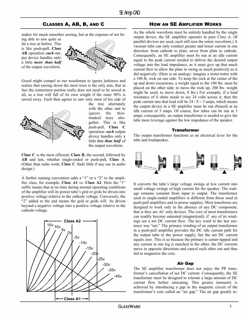
makes for much smoother sawing, but at the expense of not be-ing able to saw quite as fat a tree as before. This is like push-pull, Class AB operation: each out-put device handles only a little more than half of the output waveform. Greed might compel to our woodsmen to ignore jerkiness and realize that sawing down the most trees is the only aim, that in fact the centermost portion really does not need to be sawed at all, as a tree will fall of its own weight if the outer 90% is sawed away. Each then agrees to saw only most of his side of
the tree alternately with the other and to ignore the thin-trunked trees alto-gether. This is like push-pull, Class C operation: each output device handles only a little less than half of the output waveform.
Class C is the most efficient; Class B, the second, followed by AB and last, whether single-ended or push-pull, Class A. (Other than radio work, Class C finds little if any use in audio design.) A further naming convention adds a “1” or a “2” to the ampli-fier class, for example, Class A1 vs. Class A2. Here the “1” suffix means that at no time during normal operating conditions of the amplifier will its power tube’s grid or grids be driven into positive voltage relative to the cathode voltage. Conversely, the “2” added to the end means the grid or grids will be driven beyond a negative voltage into a positive voltage relative to the cathode voltage.
HOW AN SE AMPLIFIER WORKS As the whole waveform must be entirely handled by the single output device, the SE amplifier operates in pure Class A. (If parallel devices are used, each still sees the entire waveform.) A vacuum tube can only conduct greater and lesser current in one direction: from cathode to plate, never from plate to cathode. Consequently, an SE amplifier must be run at an idle current equal to the peak current needed to deliver the desired output voltage into the load impedance, as it must give up that much current flow to allow the plate to swing as much positively as it did negatively. (Here is an analogy: imagine a teeter-totter with a 100 lb. rock on one side. To keep the rock at the center of the up and down excursions, a weight equal to the 100 lbs. must be placed on the other side; to move the rock up, 200 lbs. weight might be used; to move down, 0 lbs.) For example, if a load resistance of 8 ohms needs to see 24 volts across it, then the peak current into that load will be 24 / 8 = 3 amps, which means the output device in a SE amplifier must be run (biased) at an idle current of 3 amps. Of course, few tubes can be run at 3 amps; consequently, an output transformer is needed to give the tube more leverage against the low impedance of the speaker.
Transformer The output transformer functions as an electrical lever for the tube and loudspeaker.
It converts the tube’s large voltage swings at low current into small voltage swings of high current for the speaker. The watt-age remains constant from input to output. The transformer used in single-ended amplifiers is different from those used in push-pull amplifiers and in power supplies. Most transforms are designed to work only in the absence of any DC component, that is they are AC only devices. The core of most transformers can readily become saturated (magnetized), if any of its wind-ings see a net DC current flow. The key word in the last sen-tence was “net.” The primary winding of an output transformer in a push-pull amplifier provides the DC idle current path for the output tube to the power supply, but the net DC current equals zero. This is so because the primary is center-tapped and any current in one leg is matched in the other; the DC currents move in opposite directions and cancel each other out and thus fail to magnetize the core.
Air Gap The SE amplifier transformer does not enjoy the PP trans-former’s cancellation of net DC current. Consequently, the SE transformer must be designed to tolerate a large amount of DC current flow before saturating. This greater immunity is achieved by introducing a gap in the magnetic circuit of the transformer’s core called an “air gap.” The air gap greatly re-
V o l t a g e C u r r e n tP o w e r
5v0v
-5v-10v
-15v-20v
-25v-30v
-35v
10v15v
-40v
Class A1
Class A2
CLASSES A, AB, B, AND C
5

GlassWare
SE Amp CAD
duces the potential inductance of the transformer while greatly extending its linear operating range in the face of a strong DC magnetizing current. Too great an air gap and the transformer falls off too quickly at the lower frequencies, too little an air gap and the transformer will not put out the full potential watt-age of the output tube. Basically, power Vs bandwidth.
B+ and Idle Current The output tube sees the reflected impedance of the speaker multiplied by the step down ratio (winding ratio) of the output transformer squared. For example, a transformer with a winding ratio of 20 will reflect the 8 ohms of the speaker as 3200 ohms to the tube: 20² = 400, 400 * 8 = 3200. Consequently, if we wish to deliver 16 watts into the 8 ohm speaker, we will have to deliver at least 16 watts into the primary impedance of the out-put transformer. Using the following variation on Ohm’s law: E = √(PR) * √2 (P is in RMS watts and E is in peak volts here), we see that if we want to deliver 16 watts into 3200 ohms, we must develop 320 volts across the 3200 ohms and the peak cur-rent into this load would need to be 0.1 amps, as I = E / R, in this case, 0.1 = 320 / 3200. Thus we have our base B+ voltage and idle current for the output tube: 320 volts and 100 ma. Of course these figures are overly optimistic, as the tube will not be able to source the needed 100 mA with 0 volt cathode to plate differential. Here is where art joins science in designing an SE amplifier output stage. There is no one perfect circuit configuration. Picking many operating points for the output tube can yield many correct output wattages and distortion fig-ures and tube life expectancies.
Positive Voltage Swings One conceptual difficulty many have with the transformer cou-pling of the output stage to the load is “Where does the other half of the voltage swing come from?” Let us start with the part that is obvious: as the tube conducts more current, the output tube can pull its connection to the primary towards the cathode voltage. But where does the positive voltage in excess of the B+ voltage on the plate come from? In other words, how is it possi-ble for the plate voltage to exceed the voltage of the power sup-ply? The answer lies in the nature of the inductive component of the output transformer. The primary and secondary are in-ductively coupled, tightly so—a change current flow in one will induce a current flow in the other. Furthermore, the trans-former’s core is immersed in the same strong electromagnetic field induced by the flow of DC current through the primary, which results in partially magnetizing the core material. Once the magnetizing current is removed from the primary winding, the field created by this winding will col-lapse and the core will snap back to its original non-polarized state, all
500v
300v
100v0v
300v
0v
of which will create a countervailing electromotive force in the primary and secondary windings that develops a peak voltage equal to idle current multiplied against the reflected impedance of secondary, which will then be added to the existing B+ volt-age. For example, if we quickly pulled the output tube from its socket while it operated at the idle current of 100 mA with 320 volts on the plate and a secondary impedance of 3200 ohms, the plate-primary connection would swing up to 640 volts. This removing of the tube is functionally equivalent to turning the tube’s conduction completely off by applying a sufficiently negative voltage to its grid. Of course, when playing music, there is a smoothly varying of plate current and not the abrupt cessation of conduction that results from yanking the tube, but the principle remains the same: if the tube quickly moves into conduction beyond the idle current value, the plate will swing negative in relation to the B+ voltage and if the tube moves quickly into a conduction less than the idle current value, the plate will swing positive in relation to the B+ voltage.
Power Supply Perturbations & Noise Since the output tube will experience twice the idle current at one end of the waveform and no current at the other end, does this mean that the power supply will become burdened by the wild swings in current draw? No, is the quick answer. The same inductive attribute that gave the plate the ability to swing more positively than the B+ voltage, gives the SE amplifier effec-tively a constant current draw regardless of wild current swings. The output transformer acts like the choke in a power supply circuit. Just as the amplifier is buffered from the wild voltage spikes of the power by the strongly inductive component of the choke, the power supply is buffered from the amplifier’s vary-ing current demands by the strongly inductive component of the transformer. If the transformer were replaced by a high wattage resistor whose value equaled that of the transformer’s reflected
impedance, the power supply would then see all of the current variations in the output tube operation.
This rosy scenario is tarnished by the poor power supply rejec-tion ratio of the output tube in an SE amplifier. Yes, the power supply is shielded from much of the plate voltage and current swings of the output tube and the output tube itself is greatly shielded from power supply noise, as the plate impedance is usually one third of the reflected impedance of the primary, which results in ¼ of noise making it to the plate: power supply
B+
0v
B+
0v
300v
Pentode SE AmplifierTriode SE Amplifier
HOW AN SE AMPLIFIER WORKS
6

GlassWare
SE Amp CAD
DESIGN PROCEDURE The first step in designing an SE amplifier is to decide on how power must be produced by the output stage. Just 1 watt or 3, 5, 8, 15, 20, 30 50, or 70 watts? Before you answer, consider this: one great attribute of single-ended amplifiers is the effortless dynamic shadings they usually render. From almost inaudible to whisper level to crescendo, the well-designed SE amplifier will startle jaded listeners with its ability to reveal the sub-dynamics of a recording. A good 8 watt SE amplifier may sound ten times more powerful at low volume levels than a 200 watt push-pull solid-state amplifier with lots of feedback. It is this wonderfully dynamic quality that compels many a listener to play the SE amplifier beyond its comfortable range. It is as if you had just found the most exhilarating sports car, nimble and agile, quickly responsive, but disappointingly not able do over 40 mph. Conclusion: you will probably need more watts that you presently think. The amount of power needed narrows the choice of tubes, unless you are willing to parallel many smaller tubes. Thus it is the choice of output tube that must come sec-ond.
The next step is to chose the output transformer. The old rule was to use a transformer with a primary impedance twice that of the tube’s rp. And, in general, this is a good starting point. The third step is to determine the output circuit topology. Indi-rectly heated cathodes or directly? AC or DC on the heaters? Cathode biased or fixed biased? The fourth step is to decide what the cathode-to-plate voltage will be and how much current to run through the stage. Here is where SE Amp CAD really comes in handy. Click the B+, current, and grid voltage controls and watch the load-line and IV points displayed on the tube’s plate curves until the best operation points are found. Once these four steps have been completed, the input stage can be considered. In other words, once the needed grid voltage swings are known, the input stage’s drive requirements are also known.
Design Trick For the advanced builder, the design trick is to alter the design order. Working on the assumption that the best output trans-former is still not as good as the worst tube, select the best pos-sible transformer as the first step. Next, hook the transformer’s secondary up to a dummy 8 ohm load and attach a signal gen-erator to the primary winding through a 10k potentiometer which has its center scraper connected to one of the outside leads. Now observe the waveform fidelity on an oscilloscope while rotating the potentiometer’s shaft. At some “magic” se-ries resistance value from the potentiometer, the waveform will pass most cleanly. Write down the value and limit your choice of output tubes to those whose rp approaches that of the “magic” value. Once the output tube is chosen, proceed with the design of the output circuit topology. Then move on to the B+ and idle current decisions and from there to the input circuit design.
Shunt Feed (AKA Para Feed) The shunt feed SE amplifier is all the rage with tube amplifier aficionados these days. The electrical functioning of the amplifier is almost identically with a conventional SE amplifier. The same load lines and operating points are used, but the output transformer is not in series with the tube’s idle current; instead, the idle current flows through a choke that serves as constant current source for the output tube, as its impedance is huge compared to the rp of the tube. A capacitor connects the output transformer to the plate and couples the AC signal from the plate into the transformer, which in turn couples the signal to the speaker. Because the transformer sees no DC current, it need not be air-gapped. Thus, one advantage of this circuit is
that high quality, nickel core transformers can be used without the usual early saturation that would occur in a conventional setup. The second ad-vantage is a huge reduction in noise at the output, as the choke buffers the plate from the power supply noise.
Se Amp CAD can be used to evaluate a shunt feed circuit. The trick is to define an output transformer that embodies the DC resistance of the plate load choke that will be used and the primary impedance of the output transformer that will be used. The value of the needed coupling capacitor can be found by this simple formula:
C (in µf) = 159155 / Resistance / Frequency
For example,
1.77 µf = 159155 / 6k / 15 Hz.
B+
0vShunt Feed SE Amplifier
noise * Rl / (rp + Rl). Unfortunately, the speaker does not di-rectly attach to the plate. The voltage across output transformer primary stepped down is what the speaker will receive. The transformer sees ¾ of the noise and that noise is coupled through the transformer to the speaker. The low rp, which had proved wonderfully advantageous in lowering the output im-pedance of the amplifier, here proves to be a detriment to low noise operation. High impedance devices like pentodes and MOSFETs yield much smaller amounts of noise to the speaker because the primary impedance is so small compared to their extremely high (nearly infinite) internal impedance. However, in the absence of feedback, these devices make for an unac-ceptably high output impedance and, consequently, a poor damping-factor. Because the triode based single-ended ampli-fier will pass more of the power supply noise to the speaker, a clean, smooth power supply is critical.
HOW AN SE AMPLIFIER WORKS
7

GlassWare
SE Amp CAD
CIRCUIT VARIABLES Circuit variables, such as tube type, B+ voltage, cathode resis-tor values, and grid voltage values are entered in field boxes at the left or changed by clicking the increment controls at the field box's left. The results are then displayed at the program's right in the schematic, the plate curves, the virtual oscillo-scope traces, and the result panel.
The increment buttons serve to increase or decrease the value in the corresponding edit field boxes by 1 or 10 or 100 or 1,000 units, depending on the variable being adjusted. For example, the smallest incre-ment for the grid voltage is 1 volt, but for the primary impedance the smallest incre-ment is 10 ohms.
When entering large values directly, such as, 105,000 the easier entry method is to type “105” and then “k.” Similarly, if en-tering 1,100,000, the quick way is to enter “1.1” followed by “m.”
After a change in value of a circuit variable, those results that are determined at least in part by that variable are displayed in fuchsia, until the “Calculate” button has been pressed, which will restore the font color to aqua. If an error condition exists, such as excessive plate dissipation, the result’s font color turns to red and returns to aqua when the problem has been corrected.
Output Transformer The output transformer can be selected or user defined from the drop-down list or from the transformer dialog box, which is accessible from the “Tools” heading on the menu bar or the right mouse button speed menu.
DATA RESULTS SE Amp CAD divides the results of its calculations into several groups: the output transformer; to the output tube; the maxi-mum ratings output tube; the current-voltage relationships that the output stage will experience because of the specified input voltage swings; the output stage (output tube, cathode resistor and bypass capacitor); and those that pertain to the load being driven by the amplifier.
One point worth remembering is that some of the results are harder than others. This means that the amount of heat created from the idle current flowing through the cathode resistor is very hard, as the actual heat generated would differ only to the degree that the resistor’s tolerance is off and the amount of leakage current the bypass capacitor pulls away from it. On the other hand, the amount of 3rd harmonic distortion is less hard, as an actual triode would differ from not only all other similar triodes, but even itself over time. This means that an actual tri-ode may prove better or worse in an actual circuit. The accept-able range of variation between samples of a tube type might 5% at one factory and 30% at another. Before the tube user turn away from tubes in disgust, remember that 30% tolerance with transistors would be considered fantastically matched, as 300% is sometimes sold as matched.
The practical effect of this variation in tubes is that the bias voltage that SE Amp CAD calculates should be close to what an actual, particular tube would need in reality and, conse-quently, some tweaking will be almost always required. The trap to avoid is the belief that exact values are needed or even beneficial in most audio work. The simple truth is that there is seldom any call for 0.01% parts in most audio construction pro-jects.
The last point to remember is that the output transformer is the truly weak link in this audio chain. Particularly at high frequen-cies, the transformer’s contribution to final distortion is great. This can be established by attaching a probe to the plate Vs the output of the transformer in a zero-feedback amplifier. (Distortion in non-feedback amplifiers increases from the first stage to the second to the last stage, the output transformer in most cases. Distortion in feedback amplifiers decreases from the first stage to the second to the last stage.)
8

GlassWare
SE Amp CAD
The list of tubes that are known to SE Amp CAD can be brought up by clicking “Tools” on the menu bar and then click-ing “Tube List.”
µ refers to a triode’s amplification factor or mu.
gm refers to a triode’s transconductance and is
measured in milliamps/volt.
rp refers to a triode’s plate resistance.
Imax refers to a triode’s maximum plate current and is measured in milliamps.
Vmax refers to the maximum static plate voltage at which a triode should be operated.
Wmax refers to the maximum static plate dissipation (watts) which a triode should undergo in normal operation.
Vh refers to the required heater voltage.
Ih refers to the required heater current in amps.
Cgp refers to a triode’s grid to plate capacitance in pf.
After checking one of the tube type choice eyelets, pressing the up and down arrow keys will move the selected tube up and down the list, which allows the user to compare quickly the characteristics of all the triodes available. (Some tubes differ in name and shape of envelope, but not in essential electrical char-acteristics, 6080 and 6AS7 for example)
The values displayed have been culled from various sources: old tube manuals, current product specification sheets, and tube related web sites. All of which means that all the data should be viewed as slightly suspect. The maximum voltage ratings for the original EL34 or KT88 are no longer valid for the current stock of these types ( much too high for new EL34’s or KT88’s.) but the 6L6’ maximum voltage, as specified a 1950’s tube manual, is too low. Furthermore, tubes do not necessarily conform their original size specifications; EL34’s come in all sizes and shapes and colors. Beyond the changes in maximum ratings and differences in size, the essential characteristics were never constant. By this we mean that the mu, rp, and Gm of a triode are not constant across all voltages and/or currents. The mu varies the least of the three, but it still varies. The values for
these characteristics were derived from one set of plate voltage and current and are valid for only that set. SE Amp CAD uses the mathematically derived value for these variables at any voltage or current.
Because the mathematical modeling of a triode is both complex and involved, user defined tubes cannot be added. If you have a tube you want added to the list, drop us a line (if you can send actual curve traces of the tube, all the better, as tube manual graphs are very suspect. Contrary to public opinion these graphs are not always derived from a curve tracer (20 points of data and a French curve worked just fine for many tube companies.)
Tube Outlines and Base Schematics While in the Tube List dialog box, a tube’s base pin out schematic or its profile can be seen by pressing the “Base” or the “Profile” buttons.
The tube profile outlines are marked in millimeters. The tube base schematics are shown from the bottom of the tube (where the pins are).
TUBE LIST
9

GlassWare
SE Amp CAD
What we like best about the triode vacuum tube is its amazing linearity, the consistent incremental change in plate current relative to incremental changes in the grid-to-cathode voltage. But not even the 300B or 845 is perfectly linear: as voltage in-creases and/or current decreases, nonlinearity increases. To compound problems, this movement into nonlinearity is in itself very nonlinear. Fingerprinting this nonlinearity has proven elu-sive. Here the irony of the situation is made plain: what we need to know about a triode in order to make the best use of its linearity is knowing where it is nonlinear. Tolstoy might have said “All linear devices are linear in the same way; but each nonlinear device is nonlinear in its own way.” Remember it is this unique bending that makes a 300B and a triode-connected KT88 sound different.
Enter True Curves™. GlassWare is proud to introduce a new model we call True Curves™. Based on a formula derived by John Broskie, it al-lows the modeling of triode plate curves to an unprecedented level of accuracy.
Live Curves The tube curves that SE Amp CAD displays are entirely mathe-matically derived, which means that you can specify the both the maximum current and voltage of the graph along with the
number of grid lines and the voltage step increments. Push but-ton switches toggle the display of the load line, and the IV dy-namics of the output stage. SE Amp CAD knows what both the plate voltage and current along with the grid voltage is at any point on the graph.
Transfer Function: I or V Here the deviation from linearity is easily seen. SE Amp CAD can plot the plate voltage or plate current's transfer function into the primary's impedance across the peak to peak voltage swing of the output tube's grid.
Plate Curves Here the constant plate voltage increments are plotted against sliding grid voltages. This is a less common way to display a tube's dynamic characteristics, but in may ways it is the better way to do so, as the curvature of the load is an easier read out of non-linearity than the straight load line against the variable grid curves.
Grid Curves This is the usual tube manual plate voltage/current graph. Here the change in plate current with constant grid voltage incre-ments is plotted against an increasing plate voltage.
V & I & W Limits SE Amp CAD can superimpose the voltage and current and wattage limits of a tube over the plate or grid curves. SE Amp CAD will draw red lines over the graph marking the limits. These lines set the safe use boundaries for a tube’s operation.
Live Tube Data Readouts With a normal tube manual graph of the tube’s plate curves a lot of guessing is required. For example if -30 volt grid voltage increments are used, it will take some eye calculation to deter-mine where exactly the –20 volts grid line would lie. With SE Amp CAD this is not a problem, as the program reads the mouse’s cursor movement across the plate curves and displays the tube’s grid voltage, plate voltage, plate current, rp, mu, Gm, and plate dissipation at the cursor position on the graph. As the cursor is moved, the tube data are updated and displayed.
Bitmap Copy Creation SE Amp CAD performs easy screen captures of the plate curves by creating bitmap files, which can be stored on your hard drive and used in other programs and easily printed. The file created is a Windows bitmap file and ends in BMP; its color depth matches that of your video display, which means that the file can be quite large if you are running your monitor in high or true color modes. To reduce the file size, open the image file in a paint type program and select “convert to palette image” and then select 16 or 256 colors.
PLATE CURVES
Example of how closely the true curves model matches a real tube’s graph from a tube curve tracer.
10

GlassWare
SE Amp CAD
VIRTUAL OSCILLOSCOPE SE Amp CAD not only displays the results numerically, it also displays the resulting wave forms. Its virtual oscilloscope quickly shows if the output stage is functioning close to its design objectives. The deviation from linearity (i.e. distortion) that the output stage undergoes with increasing input signal is displayed on the fly: as the active circuit variables are altered, the scope trace reflects the change in wave form.
Cursor Data Display Where the cursor rests on the trace is translated into the instantaneous plate voltage and phase angle values that are displayed in the hint line portion of the bottom of the program.
AC and DC Viewpoints An AC viewpoint ignores the negative bias voltage and the positive plate voltage and shows only the AC component of the output and input signal reference to the 0 voltage line. A DC viewpoint includes the negative bias voltage and the positive plate voltage with the DC component of the output and input signal reference to the 0 voltage line.
Wave Forms The type of input signal to the grid of the output tube can be selected in the virtual oscilloscope. SE Amp CAD displays the usual three oscilloscope wave forms: sine, square, and triangle. Sine waves are useful in showing the amplifier's ability to handle music-like signals. The square wave is useful for quickly displaying the gain and asymmetrical voltage swing of the amplifier. The triangle wave is useful for revealing the nonlinear transfer function i.e. the distorted output of the amplifier.
Bitmap Copy Creation SE Amp CAD features easy screen captures of the oscilloscope traces by creating bitmap files (*.BMP), which can be stored on your hard drive and used in other programs and easily printed.
Hint Clicking on the oscilloscope trace will invert its screen image, which might make it more easily seen.
SCHEMATIC UPDATES SE Amp CAD allows the user to see the changes in the schematic immediately, as circuit component selection is made. Furthermore, the needed component values and the resulting changes in operational voltages are also updated on the fly. The choices made in the circuit schematic define the circuit that SE Amp CAD evaluates. In addition, this schematic will be printed in the “Circuit” report.
Although SE Amp CAD deals only with the actual output stage of a SE amplifier, the number of different circuits that can be defined is large. For example, triode or triode connected pentode? Indirectly heated cathode or directly heated? If directly heated, center-tapped or not center-tapped? AC or DC through the cathode? If DC, a raw DC power supply or a regulated power supply?
The component values needed for the cathode resistor and power supply are calculated by SE Amp CAD instantly and displayed on the schematic. If you wish, the component values can be hidden, as can the circuit voltages, in order to make the schematic less cluttered when viewed. When the schematic background color turns to pink, the “Calculate” button must be pressed to recalculate the results and update the schematic values.
11

GlassWare
SE Amp CAD
SCENARIOS & SAVING CIRCUITS SE Amp CAD holds 4 temporary output circuit arrangements called scenarios. These allow for quick comparisons of results from changes both in circuit values and/or in circuit topology. Scenarios are loaded and unloaded from the menu bar under “Scenarios” and directly on the right mouse button speed menu. When am empty scenario slot label (e.g. “Scenario 1”, Scenario 2”…) is clicked, the circuit variables are saved to that memory slot and the scenario label receives a check mark. When a recall scenario slot is empty, the scenario label’s font color is grayed. As a scenario slot becomes filled, its load scenario label’s font color changes to black. To see what is being stored in the sce-nario memory slots, click “View” on the menu and then click “Review Scenarios” and the Scenario Display box will be
shown. This box contains a data grid that displays all the sce-narios with their circuit values and circuit results. The grid is fairly malleable, as it allows the user to move the data rows up or down.
SE Amp CAD also can save circuit arrangements permanently on the hard drive, to be recalled and modified at any time. For example, to recall a circuit from storage, click on the menu bar item “File” and then move down to “Recall Circuit,” which will bring up the “Recall Circuit“ dialog box. Alternatively, at any time just right mouse button click to bring up the speed menu, whose fifth and sixth items refer to storing and recalling circuit values.
REPORTS SE Amp CAD can print a report of the circuit that is currently being defined, the output tube’s plate curves, the scenarios, and the ReadMe.txt file for the program. In addition, an order form can be printed to order a copy of SE Amp CAD.
Amplifier Circuit Results This report prints the both the setup variables and results of the circuit currently being evaluated. It also prints a small IV graph with the key IV dynamic points.
Plate Curves This report prints a tube manual page set of information: plate curves, maximum ratings, tube outline and base schematic.
ReadMe Text File This report prints a copy of the ReadMe.TXT file that is located in the same directory as the main program. It covers a broad overview and FAQ for the program.
Order Form Additional GlassWare software programs can be ordered using the form printed by this selection.
Scenario Data The currently loaded scenarios are presented in an easy to compare format and printed to a single sheet of paper. To aid in making comparisons, this report contains the essential circuit variables, results, and circuit schematics to make comparisons easy.
12
GlassWare
SE Amp CAD
OPTIONS
The “Options” page allows the user to change the SE Amp CAD program itself. Size, fonts, color—all are changeable.
Add Rectification In the absence of a input drive voltage, the average and the idle current draw are the same in a SE amplifier. Because of the strong 2nd harmonic distortion inherent in the triode’s opera-tion in a SE amplifier, the average current will increase with a strong drive voltage swing. This difference between average and idle current can be included in SE Amp CAD‘s results by checking this menu option.
Hint Line Font The hint line font, which appears in the black display box at the top of the program, can be changed to another font, size, and color. Just choose an alternative font, size, and color. The new font choices will be remembered next time the program is run.
Don’t Show Hint Balloons Some user just love the hint balloons; others just hate them. De-cide which group you belong to and press the “Don’t show hint balloons” button to stop or start the display of hint balloon mes-sages. This choice will be remembered next time the program is run.
Background Color The normally black hint line background can be changed to an-other color. Just choose an alternative color. This choice will be remembered next time the program is run.
Expand SE Amp CAD Unbelievably, there are people with 14 inch monitors who insist on running them at 1280 x 1024 resolution. How their eyes must ache. By pressing the "Expand SE Amp CAD" button, some aid can be had. Fortunately, this choice will be remem-bered next time the program is run.
On the other hand, if your monitor is plenty big and you are running at a higher resolution, then try resizing the program. If there is enough room, SE Amp CAD will display in a fully ex-panded mode, which can be seen in the illustration in the intro-duction of this manual.
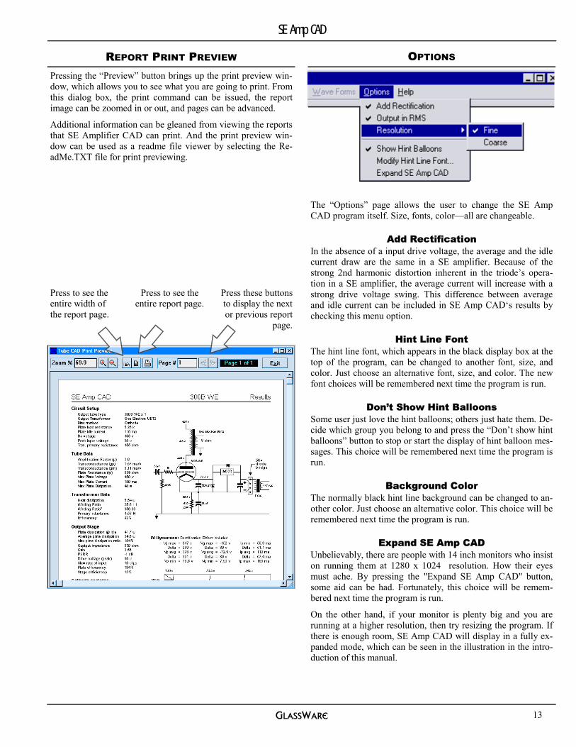
Press these buttons to display the next or previous report
page.
Press to see the entire report page.
Press to see the entire width of the report page.
REPORT PRINT PREVIEW Pressing the “Preview” button brings up the print preview win-dow, which allows you to see what you are going to print. From this dialog box, the print command can be issued, the report image can be zoomed in or out, and pages can be advanced.
Additional information can be gleaned from viewing the reports that SE Amplifier CAD can print. And the print preview win-dow can be used as a readme file viewer by selecting the Re-adMe.TXT file for print previewing.
13

GlassWare
SE Amp CAD
EVALUATION DIALOG BOX After defining all the circuit variables, such as B+ voltage, idle current, and plate load resistance, SE Amp CAD can search for error conditions and provide error descriptions and remedies.
Error List The errors caught are of the gross kind—excessive plate volt-age, excessive plate dissipation, current—that could damage the tube or greatly compromise the circuit’s performance. Each line represents one type of error.
Error Description When a line in the Error List box is selected, a description of that error is displayed below in the Error Description bracket. Each error gets its own explanation.
Error Remedies
Each type of error finds its remedy displayed in the Error Remedies bracket. Not every solution need be tried, as a change in one the variables usually results in a change more than one operating parameter.
Make It So Pressing the "Make it so" button will let SE Amp CAD correct the error conditions for you. It does this by auto-loading the circuit part values and operating points that will return the cir-cuit to normal and eliminate the error conditions.
QUICK HELP The Quick Help window provided by this program is not part of the Windows’ help data base, hypertext program. It is less cum-bersome and quicker, although much less weighty (unlike this manual). To bring it up, just press the “F1” key when a control has emphasis (Computerese for when you move the mouse into a data entry box or have checked an options eyelet) or outside mouse button click to bring up the speed menu, whose first en-try is “Quick Help”; or when the cursor is over a description label, press the button, which appears below the label, and Quick Help comes up instantly. One good idea, if you have the screen area for it, is to leave the Quick Help window up and running while you use the program, as it will track your move-ments.
As for 1-800 help lines, there are none. As for 1-900 you-pay-for help line, ditto. (Please limit your calls to program related problems, as we cannot answer your tube audio design prob-lems. Well actually we could, but we cannot spend the whole jawing audio. Sorry.) Our phone number is 831-438-5778. As for e-mailing us questions, no problem. We are at
[email protected] or write us
POB 231 Fenton MI 48430
USA
a
14

GlassWare
SE Amp CAD
AC Alternating current. A flow of electricity that changes di-rection in a cyclical manor.
Air Gap The break in the magnetic circuit in the core of a choke or single-ended amplifier. This gap allows the core to withstand a much greater polarizing DC current through the primary winding without saturating the core.
Amp Short for Ampere. A unit of electrical current flow. One volt across one ohm of resistance defines 1 amp of cur-rent flow. Often the amp is too large to be used conven-iently in audio circuits and consequently the milliampere (ma, .001 amps) is used instead.
Amplification Factor a.k.a., the “mu” or “µ“ of the triode; it is the variation in plate voltage divided by the variation in grid voltage while the plate current is held constant, for example when the plate is loaded with a constant current source. The mu of a tube sets the upper limit to the gain that is realizable from a triode in a grounded cathode amplifier circuit.
Amplifier A electronic circuit that creates a copy of the input signal with an increase in voltage and/or current.
Anode The positive electrode. In a tube it is element that re-ceives the majority of electrons emitted by the cathode.
Bandwidth In audio work, the range of frequencies that does not drop below -3 dB of the average gain. For most au-dio work this range covers 20 Hz to 20 kHz.
Bypass Capacitor A capacitor that is used to provide an effec-tive AC shunting path across a circuit element—usually, a resistor.
Capacitance The physical property of a circuit component that permits it to store an electric charge, a potential differ-ence, between elements within that circuit. The unit of capacitance is the farad.
Cathode The negative electrode. In a tube it is the element that emits electrons.
DC Direct Current. A flow of electricity proceeds continuously in one direction solely.
Decibel Abbreviated dB. A unit of change in amplitude. In acoustic terms it is the smallest increment that can be heard. In electrical terms it is equal to dB = 10 log P1/P2 and dB = 20 log E1/E2.
Distortion The departure of the reproduced signal from the in-put signal. Of course, one listener's distortion can be an-other listener's bloom, sweetness, warmth, and fluidity.
EMF The Electromotive Force. Unit of measurement is the volt.
Feedback The process of sampling a portion of the output of an amplifier and feeding it back into the circuit in a manner that will tend to correct any deviation the output signal from the input signal other than gain. Feedback usually lowers output impedance and distortion and noise. It also serves to flatten and extend the frequency response of an amplifier.
Filter A frequency selective network of resistors capacitors and/or inductors that is used to tailor the frequency re-
sponse of a circuit. Frequency Response The range of frequencies to which a cir-
cuit or loudspeaker can respond. It is usually banded within -3dB points.
Class A Whether the signal swings positive or negative, the sole output device handles all of the output waveform. Class B Each output device handles exactly half of the output waveform. Class AB Each output device handles only a little more than half of the output waveform.
Class C Each output device handles only a little less than half of the output waveform.
Gm Transconductance. The measure of the change in current flow through an electronic device relative to the change in control voltage, usually the grid-to cathode voltage. Tubes are measured in mA/volt; whereas, solid state de-vices, in A/v.
Gp Plate Transconductance. Transconductance is the measure of the change in current flow through an electronic de-vice relative to the change in control voltage—in this case, plate voltage.
Gain The relative change in voltage, current, or power to the some reference voltage, current, or power.
Grid The electrode structure in a vacuum tube that surrounds the cathode and through which the cathode-emitted elec-trons flow to the plate. It is the usual current control ele-ment of the tube.
Ground A circuit’s voltage reference point. Hertz Abbreviated Hz. One cycle per second. A 100 Hz tone is
one that has 100 cycles per second. Impedance The resistance offered to the flow of alternating
current. Inductance The property of an electrical element that opposes
any change in the existing current flow. The unit of in-ductance is the Henry.
Kilohertz Abbreviated kHz. One thousand cycles per second. A 10 kHz tone is one that has 10,000 cycles per second.
Mu A triode’s amplification factor. It is a measure of the rela-tive effectiveness of the tube’s grid over the plate in con-trolling current flow through the tube.
Ohm’s Law The voltage across a resistor in a DC circuit is equal to the current times the resistance. E = IR, I = E/R, R = E/I.
PSRR Power Supply Rejection Ratio. PSRR refers to the ratio of a circuit’s change at its output relative to the distur-bance at the power supply that caused it.
Phase The measure of the angular relationships between cur-rents and voltage in an AC circuit and the angular rela-tionships between pressures in sound waves.
Power The rate at which work is done. In electrical terms, the watt and the joule. In acoustic terms, the acoustical watt.
Plate a.k.a. anode. The positive electrode in a tube, which at-tracts the majority of electrons emitted by the cathode.
GLOSSARY
15
GlassWare
SE Amp CAD
Power Supply Abbreviated PS. A circuit that supplies power to another circuit. It usually comprises a transformer, di-odes, capacitors, and sometimes a choke or regulator.
Rectification Effect The change in average current flow due to the presence of 2nd harmonic distortion in the output tubes operation. In the absence of a input drive voltage, the average and the idle current draw are the same in a SE amplifier. Because of the strong 2nd harmonic dis-tortion inherent in the triode’s operation in a SE ampli-fier, the average current will increase with a strong drive voltage swing. A quick thought experiment is to imagine an output tube with a bias voltage of –40 volts on its grid. Now if the grid were to see a voltage swing of +100 volts and –100 volts, the output waveform would be monstrously distorted. At one extreme the peak cur-rent draw would be several times that of idle and at the other, the tube would be completely turned off and con-duction would be zero. In this case the average current would be probably twice the idle current. This difference between average and idle current can pose troubleshoot problems for the SE amplifier designer, as the power transformer or filter choke or output transformer that did not saturate at idle might at full output due to the rectifi-cation effect.
RMS Abbreviated form of Root Mean Square. A.k.a. the effec-tive amplitude. The conversion of a wave value of cur-rent or voltage into a value equal to the that would result in the same amount of heat generated as a DC current or voltage would into the same load. For sine waves the conversion factor is .707 the peak value; for square waves, 1; for triangle waves, .577.
rp The plate resistance of a vacuum tube. It is the impedance that a tube offers a change in plate voltage. It is equal to mu/gm and it is not as constant as we might like, vary-ing as it does with voltage and current. A 12AX7 has a rp of 62 k, whereas a 6DJ8, 3k.
Reactor A.k.a. inductor, coil, choke. A device that introduces an inductive element into an circuit.
Regulator A circuit whose purpose is to maintain a constant output voltage in spite of variation in the power supply voltage or variations in the current drawn by the load.
Shunt Feed An alternative single-ended amplifier topology. An amplifier wherein the output transformer is not in series with the tube’s idle current, but capacitor coupled to the plate. The idle current flows through a choke that serves as a constant current source load for the output tube.
Single Ended A.k.a SE. An amplifier or circuit that uses one device ( or devices in parallel) to handle all of the output signal. By necessity this entails Class A operation of the output device.
Slew Rate The ability of an amplifier to swing so much voltage in so much time. The voltage is measured in volts and the time is measured in microseconds (µs), which gives us the final “v/µs” suffix.
Transconductance The measure of the change in current flow through an electronic device relative to the change in control voltage. Tubes are measured in mA/volt;
whereas, solid state devices, usually, in A/v. Transformer A device made up of at least two coils which
usually surround a ferromagnetic core and by induction serve to transform electrical energy from one coil to the other. In an SE amplifier this transformer is always air gapped to help the transformer handle the large magnet-izing effect of the DC current flowing through the pri-mary winding.
Triode A vacuum tube with three primary elements: the cath-ode, which emits electrons; the grid, which surrounds the cathode and offers a large amount of control over the current flow from the cathode; the plate, which encases both the cathode and the grid and receives the flow of electrons from the cathode and, to a much lesser degree than the grid, controls the flow of current from the cath-ode.
Zo The output impedance of a circuit or amplifier.
GLOSSARY
16