se1100 - digi internationalftp1.digi.com/support/documentation/0190050_b.pdf · se1100 relay...
TRANSCRIPT

SE1100Relay Output Boards
User’s Manual019–0050 • 080610–B

SE1100
SE1100 User’s Manual
Part Number 019-0050 • 080610-B • Printed in U.S.A.
© 2001–2008 Digi International Inc. • All rights reserved.Digi International reserves the right to make changes andimprovements to its products without providing notice.
Trademarks• Dynamic C® and Rabbit® are registered trademarks of Digi International
Inc.
Rabbit Semiconductor Inc.www.rabbit.com
No part of the contents of this manual may be reproduced or transmitted in any form or by any means without the express written permission of Digi Interna-tional.
Permission is granted to make one or more copies as long as the copyright page contained therein is included. These copies of the manuals may not be let or sold for any reason without the express written permission of Digi International.
The latest revision of this manual is available on the Rabbit Web site, www.rabbit.com, for free, unregistered download.

Table of Contents iiiUser’s Manual
TABLE OF CONTENTS
Chapter 1: Overview 5Features ................................................................................................. 6
Chapter 2: Getting Started 9Connecting an SE1100 to a Rabbit Controller ...................................... 10SE1100 Configuration ........................................................................... 12
Chapter 3: Software Reference 13
Appendix A: Specifications 15SE1100 Relay Expansion Board ............................................................ 16
Quick-Release Connectors .............................................................. 17
Index 19
Schematics

iv Table of Contents SE1100

User’s Manual Overview 5
CHAPTER 1: OVERVIEW
Chapter 1 gives an overview of the SE1100 relay board and its specificfeatures.

SE11006 Overview
Z-World’s SE1100 expansion boards provide a simple way to add relays toa control system built around a Rabbit controller. These relay outputboards can be connected to the digital outputs of any Rabbit controller.The SE1100 adds expansion capability even to boards without a RabbitPLCBus interface.The SE1100’s four SPDT relays are high-power relays. The relays areoptically isolated, and have fuses and filters to protect them from noise andtransients. Each relay has an LED indicator to help with system mainte-nance.Figure 1-1 illustrates a system of expansion boards mounted on a DIN railand connected to a controller. Chapter 2, “Getting Started,” providesinstructions and illustrations for connecting the SE1100 relay board to acontroller’s digital outputs.
FeaturesThe SE1100 relay board is designed to interface to the digital outputs ofany Rabbit controller. The board’s four relays have a 6.3 A fuse connectedto the common pin for overcurrent protection. In addition to the fuses, asnubber circuit across the common and the normally open/normally closedpins suppresses voltage spikes across the contacts. All of the signals fromthe four SPDT relays are brought out to header J1.The interface voltage has a range of 5 V to 24 V. A 24 V DC supply isneeded to power the relays. When driving the relays with high-voltagedrivers, an SE1100 can be located up to 15 m (50 feet) from the controller.The opto isolation between the controller and the relays provides an extralevel of assurance to guard against noise from high-voltage transients.The LEDs on the relay board indicate the status of the relays. When anLED is on, the relay associated with that LED is energized. When an LEDis off, the relay is in a default state. The default state is for the commonterminal to be connected to the normally closed terminal.The onboard linear regulator provides the regulated +5 V to all the logicelements. The relays and the LEDs are driven with the unregulated DCinput voltage. Altogether, the SE1100 draws approximately 80 mA fromthe DC power supply input when all the relays are turned on.

User’s Manual Overview 7
Relay 3 Relay 2 Relay 1 Relay 0
R20L3
J3
U1
H1
U6
C19
F1C1 C2
U3
R19L2 R18L1 R17L0
D1
C20
C17
R21 R13
R16 R33
R15 R28
R14 R27
R23 R22
R31 R32
R24 R25
R29 R30
F2C3 C4F3C5 C6F4C7 C8
R11 R12 R10R9
C18
R2
R1
R4
R3
R6
R5
R8
R7
H.C.Driver Opto
Figure 1-2. SE1100 Relay Expansion Board Layout

SE11008 Overview

User’s Manual Getting Started 9
CHAPTER 2: GETTING STARTED
10 Getting Started SE1100
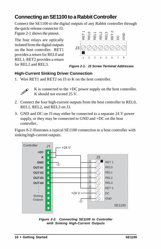
Connecting an SE1100 to a Rabbit ControllerConnect the SE1100 to the digital outputs of any Rabbit controller throughthe quick-release connector J3.Figure 2-1 shows the pinout.The four relays are opticallyisolated from the digital outputson the host controller. RET1provides a return for REL0 andREL1; RET2 provides a returnfor REL2 and REL3.
High-Current Sinking Driver Connection1. Wire RET1 and RET2 on J3 to K on the host controller.
K is connected to the +DC power supply on the host controller.K should not exceed 25 V.
2. Connect the four high-current outputs from the host controller to REL0,REL1, REL2, and REL3 on J3.
3. GND and DC on J3 may either be connected to a separate 24 V powersupply, or they may be connected to GND and +DC on the hostcontroller..
Figure 8-2 illustrates a typical SE1100 connection to a host controller withsinking high-current outputs.
Figure 2-2. Connecting SE1100 to Controllerwith Sinking High-Current Outputs
GND
J3
8
DC
RET 2
RET 12
7
6
5
4
3
REL0
REL1
REL2
REL3
1
SE1100
Controller
SinkingOutputs
GN
D
J3
1 8
DC
RE
T 2
RE
T 1
2 76543
RE
L0
RE
L1
RE
L2
RE
L3
Figure 2-1. J3 Screw Terminal Addresses

User’s Manual Getting Started 11
High-Current Sourcing Drivers or TTL/CMOS Connection1. Wire RET1 and RET2 on J3 to GND on the host controller.
K is connected to the +DC power supply on the host controller.K should not exceed 25 V.
2. Connect the four high-current outputs or the TTL/CMOS outputs fromthe host controller to REL0, REL1, REL2, and REL3 on J3.
3. GND and DC on J3 may either be connected to a separate 24 V powersupply, or they may be connected to GND and +DC on the hostcontroller..
Figure 2-3 illustrates a typical SE1100 connection to a host controller withsourcing high-current outputs.
Figure 2-3. Connecting SE1100 to Controllerwith Sourcing High-Current Outputs
GND
J3
8
DC
RET 2
RET 12
7
6
5
4
3
REL0
REL1
REL2
REL3
1
SE1100
Controller
SourcingOutputs

12 Getting Started SE1100
SE1100 ConfigurationThe SE1100 board holds four high-power relays. Each SE1100 relay hasthe following specifications:• Standard coil voltage 24 V DC.• Contact ratings:
10 A at 24 V DCor 120 V AC,7 A at 250 V AC resistivemaximum.
Pin 1 is the common. Pin 5 goes to a high-voltage/high-current driver onthe relay board. Pin 2 is for the actuation voltage. Turning on the driverallows current to flow through the coil, switching on the relay. Pin 3 is thenormally open contact. Pin 4 is the normally closed contact.Each relay is protected by a 6.3 A fuse on pin 1. To help eliminatetransients, a resistor/capacitor pair is attached between pin 1 and pin 3 oneach relay. An LED is connected in line with the coil on each relay, andlights up when current passes through the coil.
Althought the relays are rated at 10 A, they are protected with6.3 A fuses because the size of the traces on the printed circuitboards limits the current through each relay to 6 A.
Header J1 is used to connect external devices to the relays.Figure 2-5 illustrates the pinouts for the relay connection pins on header J1.
Figure 2-5. Relay Connection Pins
Figure 2-4. Relay Circuit
C O M C O M C O M C O M
C = normally closed
O = normally open
M = common
J1
1 12
Relay 3 Relay 2 Relay 1 Relay 0

Software Reference 13User’s Manual
CHAPTER 3: SOFTWARE REFERENCE

SE110014 Software Reference
There are no software drivers unique to the SE1100 expansion boards.Since the SE1100 is driven by the digital outputs of the host controller it isconnected to, the drivers associated with the host controller’s digitaloutputs will operate the relays on the SE1100.The following sample program shows how to use the SE1100 withZ-World’s BL1700 controller.
17SE1100.C
/* REL0 to U2, 0 REL1 to U2, 1 REL2 to U2, 2 REL3 to U2, 3 RET1 to RET2 to DC to BL1700, DCIN GND to U2, GND*/
#use vdriver.lib#use eziobl17.lib
main()unsigned long t;VDInit(); // hits watchdog periodicallyeioBrdInit(0); // initialize boardwhile(1)
t = MS_TIMER;printf("on\n");while((MS_TIMER – t) < 1000L)
outport(0x4100, 1);outport(0x4100, 3);outport(0x4100, 5);outport(0x4100, 7);
t = MS_TIMER;printf("off\n");while((MS_TIMER – t) < 1000L)
outport(0x4100, 0);outport(0x4100, 2);outport(0x4100, 4);outport(0x4100, 6);

Specifications 15User’s Manual
APPENDIX A: SPECIFICATIONS

SE110016 Specifications
Table A-1. SE1100 Specifications
Feature Specification
Board Size 2.835" × 3.85" × 1.32" (72.0 mm × 97.8 mm × 33.5 mm)
Operating Temperature –40°C to +70°C
Humidity 5% to 95%, noncondensing
Input Voltage and Current 24 V DC, 80 mA
Relays 4 SPDT relays
6.3A at 125 V AC or 6.3A at 24 V DC
0.175 typ(4.4)
0.17
5 ty
p(4
.4)
0.187 dia, 4x(4.7)
3.85(97.8)
~1.1
7(2
9.7)
~1.
32(3
3.5)
2.83
5(7
2.0)
1.975(50.2)
0.825(21.0)
SE1100 Relay Expansion Board
Figure A-1. SE1100 Dimensions

Specifications 17User’s Manual
Quick-Release ConnectorsThe SE1100 comes equipped with quick-release connectors that allow forquick connection/disconnection. Figure A-2 illustrates the connectors andprovides their dimensions. Table A-2 provides the specifications.
Figure A-2. Quick-Release Connectors
26.0
5.8
6.3
2.5
12.6
15.5
5.0
3.85
8.35
3.5
2.5
1.0
3.9
12.0
5.0
(a) Quick-Release Female Connector
(b) Quick-Release Male Connector

SE110018 Specifications
Table A-2. Quick-Release ConnectorsSpecifications
Feature Specification
Maximum Voltage, Current 15 A @ 300 V
Insulation Resistance 100 GΩ
Wire AWG #12–#26 stranded#14–#26 solid
Stripping Length 310 inches
Withdrawal Force Meets UL 486
Torque 7 inches per pound

User’s Manual Index 19
INDEX
Bboard layout ..................................7
Ccoil voltage ................................. 12connecting expansion boards14, 11connection
sinking driver .......................... 10sourcing driver ........................ 11
connectorsquick-release ........................... 17
contact ratingsrelays ...................................... 12
Ddimensions
SE1100 ..................................... 16
Ffeatures .........................................6fuses ........................................... 12
Hheaders
J1 ............................................. 12J3 ............................................. 10
Iinstallation
SE1100 expansion boards ........ 10
LLEDs .............................................6
Nnoise transients .............................6
Ppinout .......................................... 10
Qquick-release connectors ............ 17
Rrelay
control .......................................6
Ssample programs
17SE1100.C .............................. 14SE1100 ..................................... 14
softwareSE1100 ..................................... 14
specificationsquick-release connectors ........ 18relays ...................................... 12SE1100 ..................................... 16

SE110020 Index

User’s Manual Schematics
SCHEMATICS
090-0063 SE1100 Schematicwww.rabbit.com/documentation/schemat/090-0063-00.pdf
You may use the URL information provided above to access the latestschematic directly.