se340-ah-omi-010 - navy tribe · figure 5-6 receiving signal flow diagram (sheet 3 of 5)...
TRANSCRIPT

Figure 5-6 Receiving Signal Flow Diagram (Sheet 3 of 5)
SE340-AH-OMI-010
5-47 / (5-48 Blank)

5-48@@FIpgtype@@BLANK@@!FIpgtype@@

Figure 5-6 Receiving Signal Flow Diagram (Sheet 4 of 5)
SE340-AH-OMI-010
5-49 / (5-50 Blank)

5-50@@FIpgtype@@BLANK@@!FIpgtype@@

Figure 5-6 Receiving Signal Flow Diagram (Sheet 5 of 5)
SE340-AH-OMI-010
5-51 / (5-52 Blank)

5-52@@FIpgtype@@BLANK@@!FIpgtype@@

Figure 5-7 Primary Power and High Voltage Power, Distribution and Control Diagram
SE340-AH-OMI-010
5-53 / (5-54 Blank)

5-54@@FIpgtype@@BLANK@@!FIpgtype@@

Figure 5-8 +28 VDC Regulated Power, Distribution and Control Diagram
SE340-AH-OMI-010
5-55 / (5-56 Blank)

5-56@@FIpgtype@@BLANK@@!FIpgtype@@

Figure 5-9 +28 VDC Control Power, Distribution and Control Diagram (Sheet 1 of 2)
SE340-AH-OMI-010
5-57 / (5-58 Blank)

5-58@@FIpgtype@@BLANK@@!FIpgtype@@

Figure 5-9 +28 VDC Control Power, Distribution and Control Diagram (Sheet 2 of 2)
SE340-AH-OMI-010
5-59 / (5-60 Blank)

5-60@@FIpgtype@@BLANK@@!FIpgtype@@
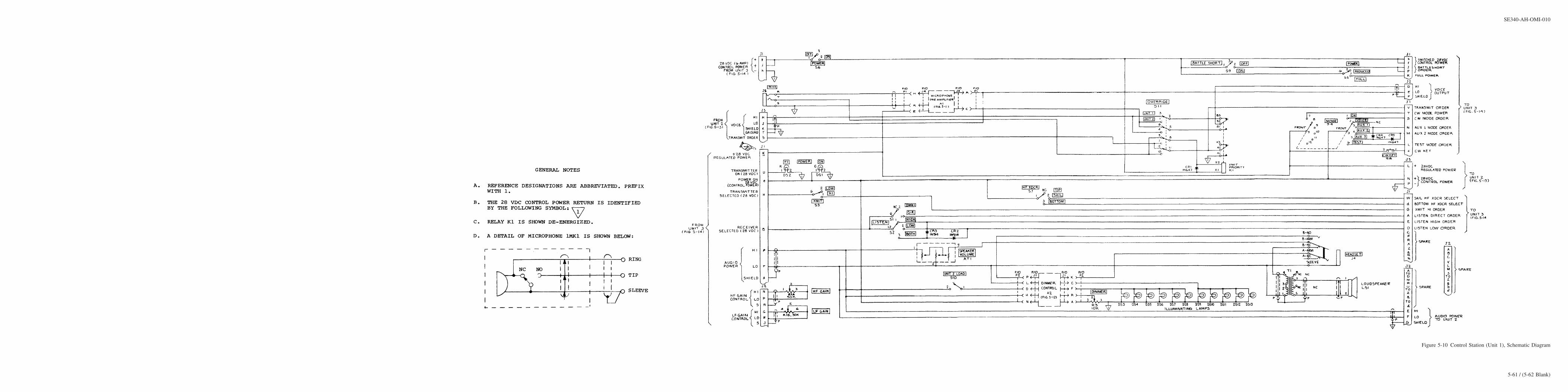
Figure 5-10 Control Station (Unit 1), Schematic Diagram
SE340-AH-OMI-010
5-61 / (5-62 Blank)

5-62@@FIpgtype@@BLANK@@!FIpgtype@@

Figure 5-11 Microphone Preamplifier (1A1 or 2A1), Schematic Diagram
SE340-AH-OMI-010
5-63 / (5-64 Blank)

5-64@@FIpgtype@@BLANK@@!FIpgtype@@

Figure 5-12 Dimmer Control (1A2), Schematic Diagram
SE340-AH-OMI-010
5-65 / (5-66 Blank)

5-66@@FIpgtype@@BLANK@@!FIpgtype@@

Figure 5-13 Remote Control Station (Unit 2), Schematic Diagram
SE340-AH-OMI-010
5-67 / (5-68 Blank)

5-68@@FIpgtype@@BLANK@@!FIpgtype@@

Figure 5-14 Receiver-Transmitter (Unit 3) Schematic Diagram (Sheet 1 of 2)
SE340-AH-OMI-010
5-69 / (5-70 Blank)

5-70@@FIpgtype@@BLANK@@!FIpgtype@@

Figure 5-14 Receiver-Transmitter (Unit 3) Schematic Diagram (Sheet 2 of 2)
SE340-AH-OMI-010
5-71 / (5-72 Blank)

5-72@@FIpgtype@@BLANK@@!FIpgtype@@

Figure 5-15 Power Supply and Test Panel Assembly (3A1), Schematic Diagram (Sheet 1 of 2)
SE340-AH-OMI-010
5-73 / (5-74 Blank)

5-74@@FIpgtype@@BLANK@@!FIpgtype@@

Figure 5-15 Power Supply and Test Panel Assembly (3A1), Schematic Diagram (Sheet 2 of 2)
SE340-AH-OMI-010
5-75 / (5-76 Blank)

5-76@@FIpgtype@@BLANK@@!FIpgtype@@

Figure 5-16 +28 VDC Regulated Power Supply (3A1A1), Schematic Diagram
SE340-AH-OMI-010
5-77 / (5-78 Blank)

5-78@@FIpgtype@@BLANK@@!FIpgtype@@

Figure 5-17 Meter and Muting Circuit (3A1A2), Schematic Diagram
SE340-AH-OMI-010
5-79 / (5-80 Blank)

5-80@@FIpgtype@@BLANK@@!FIpgtype@@

Figure 5-18 Receiver-Transmitter Assembly (3A2), Schematic Diagram
SE340-AH-OMI-010
5-81 / (5-82 Blank)

5-82@@FIpgtype@@BLANK@@!FIpgtype@@

Figure 5-19 Speaker Amplifier (3A2A1), Schematic Diagram
SE340-AH-OMI-010
5-83 / (5-84 Blank)

5-84@@FIpgtype@@BLANK@@!FIpgtype@@

Figure 5-20 Driver Amplifier and LF Equalizer (3A2A2), Schematic Diagram
SE340-AH-OMI-010
5-85 / (5-86 Blank)

5-86@@FIpgtype@@BLANK@@!FIpgtype@@
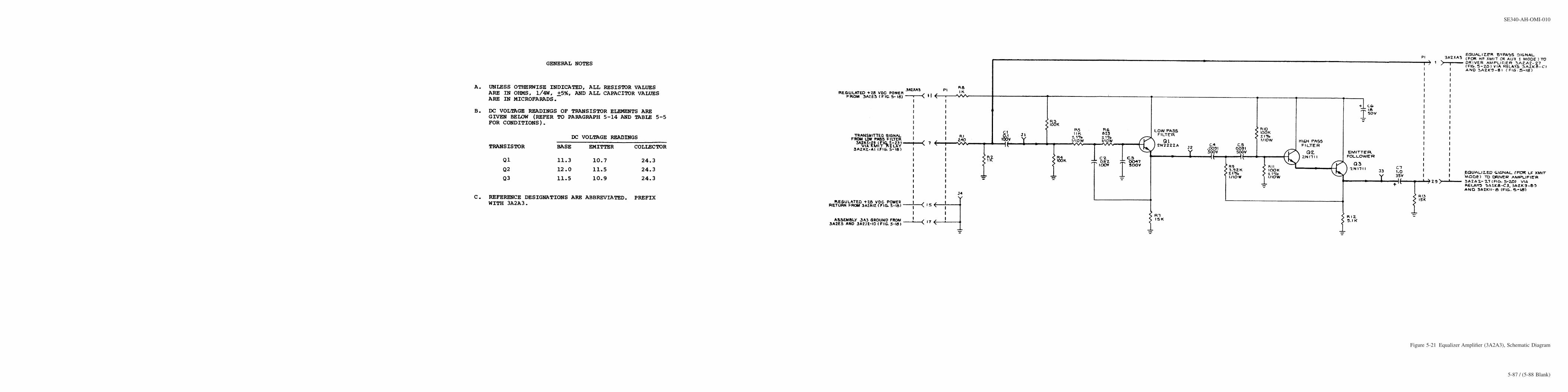
Figure 5-21 Equalizer Amplifier (3A2A3), Schematic Diagram
SE340-AH-OMI-010
5-87 / (5-88 Blank)

5-88@@FIpgtype@@BLANK@@!FIpgtype@@

Figure 5-22 Test Oscillator (3A2A4), Schematic Diagram
SE340-AH-OMI-010
5-89 / (5-90 Blank)

5-90@@FIpgtype@@BLANK@@!FIpgtype@@

Figure 5-23 Low Pass Filter (3A2A5), Schematic Diagram
SE340-AH-OMI-010
5-91 / (5-92 Blank)

5-92@@FIpgtype@@BLANK@@!FIpgtype@@

Figure 5-24 Clipper Amplifier (3A2A6), Schematic Diagram
SE340-AH-OMI-010
5-93 / (5-94 Blank)

5-94@@FIpgtype@@BLANK@@!FIpgtype@@

Figure 5-25 Balanced Demodulator Low (3A2A7), Schematic Diagram
SE340-AH-OMI-010
5-95 / (5-96 Blank)

5-96@@FIpgtype@@BLANK@@!FIpgtype@@

Figure 5-26 Balanced Modulator (3A2A8), Schematic Diagram
SE340-AH-OMI-010
5-97 / (5-98 Blank)

5-98@@FIpgtype@@BLANK@@!FIpgtype@@

Figure 5-27 Microphone Amplifier (3A2A9), Schematic Diagram
SE340-AH-OMI-010
5-99 / (5-100 Blank)

5-100@@FIpgtype@@BLANK@@!FIpgtype@@

Figure 5-28 CW/Test Oscillator (3A2A10), Schematic Diagram
SE340-AH-OMI-010
5-101 / (5-102 Blank)

5-102@@FIpgtype@@BLANK@@!FIpgtype@@
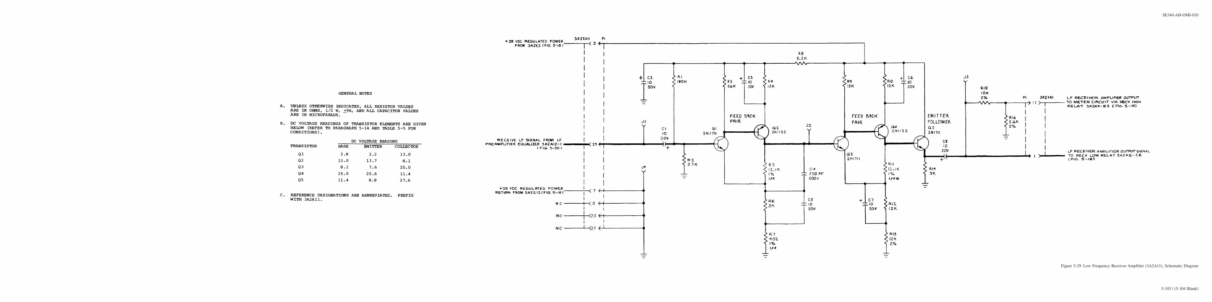
Figure 5-29 Low Frequency Receiver Amplifier (3A2A11), Schematic Diagram
SE340-AH-OMI-010
5-103 / (5-104 Blank)

5-104@@FIpgtype@@BLANK@@!FIpgtype@@

Figure 5-30 Low Frequency Preamplifier Equalizer (3A2A12), Schematic Diagram
SE340-AH-OMI-010
5-105 / (5-106 Blank)

5-106@@FIpgtype@@BLANK@@!FIpgtype@@

Figure 5-31 Balanced Demodulator High (3A2A13), Schematic Diagram
SE340-AH-OMI-010
5-107 / (5-108 Blank)

5-108@@FIpgtype@@BLANK@@!FIpgtype@@

Figure 5-32 High Frequency Receiver Amplifier (3A2A14), Schematic Diagram
SE340-AH-OMI-010
5-109 / (5-110 Blank)

5-110@@FIpgtype@@BLANK@@!FIpgtype@@

Figure 5-33 High Frequency Preamplifier Equalizer (3A2A15), Schematic Diagram
SE340-AH-OMI-010
5-111 / (5-112 Blank)

5-112@@FIpgtype@@BLANK@@!FIpgtype@@
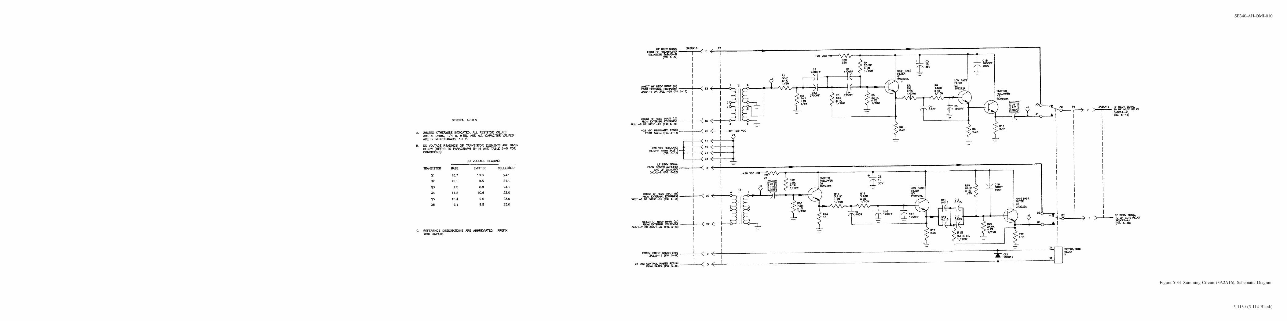
Figure 5-34 Summing Circuit (3A2A16), Schematic Diagram
SE340-AH-OMI-010
5-113 / (5-114 Blank)

5-114@@FIpgtype@@BLANK@@!FIpgtype@@

Figure 5-35 Final Amplifier Assembly (3A3), Schematic Diagram
SE340-AH-OMI-010
5-115 / (5-116 Blank)

5-116@@FIpgtype@@BLANK@@!FIpgtype@@

Figure 5-36 Low Level Final Amplifier (3A3A1), Schematic Diagram
SE340-AH-OMI-010
5-117 / (5-118 Blank)

5-118@@FIpgtype@@BLANK@@!FIpgtype@@

Figure 5-37 Final Amplifier Protection Circuit, 3A3A2 Schematic Diagram
SE340-AH-OMI-010
5-119 / (5-120 Blank)

5-120@@FIpgtype@@BLANK@@!FIpgtype@@

Figure 5-38 L.F. Circuit Card Assembly Extender Board (885-0387) Schematic Diagram
SE340-AH-OMI-010
5-121

Figure 5-39 H.F. Circuit Card Assembly Extender Board (885-0386) Schematic Diagram
SE340-AH-OMI-010
5-122

CHAPTER 6
CORRECTIVE MAINTENANCE
6-1. INTRODUCTION.
6-2.
This chapter contains instructions for the performance of corrective maintenance on Sonar CommunicationSet AN/WQC-2A. Section I of this chapter contains procedures for adjusting variable control circuits in theequipment. Section II of this chapter gives procedures for servicing and repair of the equipment.
6-3.
Before attempting to adjust or repair the equipment, the Technician should have a thorough knowledge of theequipment operating controls (Chapter 2), the functional operation of the equipment (Chapter 3), and the tech-niques used to fault isolate and troubleshoot the equipment (Chapter 5). A complete parts list for the equipmentand all parts location illustrations are given in Chapter 7.
SECTION I
ADJUSTMENTS AND ALIGNMENT
6-4. ADJUSTMENT PROCEDURES.
6-5. GENERAL.
The procedures given in this section, enable the Technician to adjust each of the variable control circuits ofthe equipment. These controls are normally factory set for optimum operation of the system and will not requirereadjustment unless the board has been repaired after damage or part failure. The procedures are given in ascend-ing order of assembly and subassembly number. All of the variable adjustments are located in Unit 3.
6-6. PRELIMINARY CONTROL SETTING.
Before proceeding with any of the adjustments in this section, place the operating controls as given in Table6-1.
WARNING
Dangerous voltages are present inside the Unit 3 cabinet when interlockswitches are set to the override position or when the Unit 1 BATTLESHORTswitch is set to ON. Use all safety precautions when servicing the equipmentunder these conditions.
SE340-AH-OMI-010
6-1

Table 6-1 Preliminary Control Settings for Adjustment Procedures
CONTROL SETTING
UNIT 3MAIN POWER ONPOWER ON/OFF ONHIGH VOLTAGE OFFUNIT 1POWER ON/OFF ONMODE TESTLISTEN DIR/OMNI OMNILISTEN HIGH/LOW/BOTH LOWHF GAIN Max. clockwiseLF GAIN Max. clockwiseXMIT HI/LOW LOWPOWER FULL/REDUCED FULLSPEAKER VOLUME MidrangeMicrophone push-to-talk Released
6-7. +28 VDC REGULATED POWER ADJUSTMENT (3A1A1).
Use the following procedure to adjust the output of the +28 VDC regulated power supply on Power Supplyand Test Panel assembly 3A1, using potentiometer R3 (figure 7-12).
a. Test Equipment Required. A DC VTVM is required for this adjustment.
b. Procedure .
1. Place assembly 3A1 in its servicing position (paragraph 6-16).
2. Remove assembly 3A1A1. Insert an extender card in its socket, and replace 3A1A1 in the extender card.
3. To provide power while servicing, override the assembly 3A1 interlock.
4. Connect the DC VTVM between connector 3A1XA1-17 on the extender card and ground.
5. Position the operating controls as listed in Table 6-1.
6. Adjust potentiometer R3 on 3A1A1 for a reading of 28 ± 1 VDC on the VTVM.
7. On completion of adjustment, remove the test equipment and extender card, and replace 3A1A1 in itssocket.
8. Restore assembly 3A1 to its normal operating condition.
6-8. MUTING TIME DELAY ADJUSTMENT (3A1A2).
Time Delay Adjustment R22 on Meter and Muting Circuit 3A1A2 is used to adjust the length of time inwhich the receiver resumes normal operation after an external muting signal is removed. By adjustment of R22the recovery time is variable from 10 milliseconds to 7. 0 seconds. Use the following procedure when it is nec-essary to check or readjust the setting of R22 (figure 7-12).
a. Test Equipment Required. Oscilloscope AN/USM-281 is required for this adjustment.
b. Procedure .
1. Place Power Supply and Test Panel Assembly 3A1 in its servicing position (paragraph 6-16). To providepower while servicing the assembly, override the chassis interlock.
SE340-AH-OMI-010
6-2

2. Position all operating controls as listed in Table 6-1.
3. Set MUTE switch S2 (located on the right interior side of the 3A1 upper chassis) to the LO position.
4. Connect the oscilloscope probe to J4 on the 3A1A2 subassembly. Connect the ground clip to the 3A1chassis. A reading of less than 1.0 VDC should be observed.
5. Connect the oscilloscope trigger input to J3 on 3A1A2. Connect a jumper between J3 and chassis ground.
6. Rotate R22 on 3A1A2 to the full counterclockwise position.
7. Set the oscilloscope trigger controls for a positive DC trigger.
8. Remove the ground jumper connection from J3. As the ground is removed, the DC level observed on thescope should change from 28V to less than 1.0V in less than 10 milliseconds.
9. Reconnect J3 on 3A1A2 to ground. Rotate R22 to the full clockwise position. The DC level on the oscil-loscope (at J4) should return to 28V.
10. Remove the ground connection from J3. As the ground is removed, the DC level observed on the scopeshould change from 28V to less than 1.0V in 7.0 seconds or more.
11. Reposition R22 for the desired muting recovery time (10 milliseconds to 7.0 seconds).
12. Remove the test equipment and reset MUTE switch S2 to its normal operating position.
13. Restore assembly 3A1 to its normal operating condition.
6-9. MECHANICAL FILTER 3A2FL1 ALIGNMENT.
Two trimmer capacitor adjustments (C1 and C2) are provided on the main chassis of the 3A2 assembly toadjust the output of mechanical sideband filter 3A2FL1. Use the following procedure to make this adjustment.
a. Test Equipment Required . Oscilloscope AN/USM-281 is required for this adjustment.
b. Procedure.
1. Place Receiver-Transmitter assembly 3A2 in its servicing position (paragraph 6-16). To provide powerwhile servicing the assembly, override the assembly interlock.
2. Position all operating controls as listed in Table 6-1.
3. Connect the oscilloscope probe to J1 on Clipper Amplifier 3A2A6. Connect the probe clip to the 3A2chassis.
4. Adjust the oscilloscope controls to view the receiver test signal properly.
5. Remove the probe from J1 and reconnect it to J4 on the 3A2A6 board, with chassis as ground. Readjustscope controls to view output signal at J4.
6. Using a small screwdriver, alternately adjust C1 and C2 on the upper center section of the 3A2 chassis toobtain a maximum peak-to-peak amplitude reading of the signal on the oscilloscope screen.
7. On completion of adjustment, remove the test equipment and restore assembly 3A2 to its normal operat-ing condition.
6-10. SPEAKER AMPLIFIER OUTPUT VOLTAGE ADJUSTMENT (3A2A1).
Output Voltage Limit Adjustment R5 on Speaker Amplifier 3A2A1 is provided to limit the output power levelof the receiver audio signal. Use the following procedure to adjust R5 (figure 7-17).
a. Test Equipment Required. Oscilloscope AN/USM-281 is required for this adjustment.
b. Procedure.
SE340-AH-OMI-010
6-3
1. Place Receiver-Transmitter assembly 3A2 in its servicing position (paragraph 6-16). To provide powerwhile servicing, override the assembly interlock.
2. Position all operating controls as listed in Table 6-1.
3. Connect the oscilloscope probe to J3 of Speaker Amplifier 3A2A1, with ground clip connected to chassis.
4. Adjust the oscilloscope controls to view the receiver test signal output. The signal should have an ampli-tude of approximately 10 volts peak-to-peak when resistor R5 is set to the maximum counterclockwiseposition.
5. Rotate R5 in the clockwise direction. The output waveform should become clipped at both the top and bot-tom.
6. Adjust R5 until clipping just begins.
7. Remove the test equipment and restore assembly 3A2 to its normal operating condition.
6-11. CLIPPER AMPLIFIER ADJUSTMENTS (3A2A6).
Two adjustments are provided on Clipper Amplifier 3A2A6. Potentiometer R13 is used to adjust the peakclipping, and R43 is used to adjust the base clipping (see figure 7-17). Use the following procedure when mak-ing these adjustments.
a. Test Equipment Required .
1. Oscilloscope AN/USM-281.
2. Signal Generator AN/URM-127.
3. Electronic Counter AN/USM-245.
4. AC VTVM AN/USM-143.
b. Peak Clipping Adjustment Procedure .
1. Place Receiver-Transmitter assembly 3A2 in its servicing position (paragraph 6-16). Remove MicrophoneAmplifier 3A2A9 from its socket. To provide power while servicing, override the assembly interlock.
2. Connect the signal generator output to J1 of 3A2A8 and chassis ground. Connect the electronic counteracross the signal generator output and set the generator frequency to 1450 ± 10 Hz.
3. Disconnect the electronic counter and connect the AC VTVM across the signal generator output.
4. Connect the oscilloscope between J3 on 3A2A3 and chassis ground and adjust the scope controls to viewa signal approximately 1V peak-to-peak in amplitude.
5. Position the operating controls as listed in Table 6-1. Make certain that the Unit 1 HIGH VOLTAGE switchis set to OFF. Depress the microphone push-to-talk switch, and hold it in the depressed position. The sys-tem should now be in the transmit mode with the high voltage off, and with the test signal originating atthe signal generator instead of the built-in test oscillator.
6. Increase the signal generator output signal level to -6 dBV or 0.5V rms.
7. While observing the oscilloscope waveform, adjust R13 on Clipper Amplifier 3A2A6 in a counterclock-wise direction until waveform decreases. Slowly readjust R13 in the opposite direction until the point isreached where there is no further increase in waveform amplitude. This is defined as the point of percep-tible clipping. Do not adjust R13 beyond this point. At this point the output signal amplitude should be 700± 70 mV peak-to-peak. The clipping level has now been set.
c. Base Clipping Adjustment Procedure .
1. Make certain that NORM/BYP switch S1 on the main chassis of 3A2 is set to the NORM position.
2. Readjust the signal generator output level to -32 dBV or 25 mV rms.
SE340-AH-OMI-010
6-4

3. If no waveform is present, adjust R43 on 3A2A6 in a clockwise direction until a waveform appears. Slowlyreadjust R43 until the scope display just disappears. Do not adjust R43 beyond this point. This setting ofR43 represents the desired base clipping level of -80 dBV.
4. Turn off the equipment. Remove the test equipment, and replace Microphone Amplifier 3A2A9 in itssocket.
5. Restore assembly 3A2 to its normal operating condition.
6-12. LOW LEVEL FINAL AMPLIFIER GAIN ADJUSTMENT (3A3A1).
Use the following procedure to adjust the gain of Low Level Final Amplifier 3A3A1, using potentiometerR32 (figure 7-36).
a. Test Equipment Required . An AC VTVM AN/USM-143 is required to perform this adjustment.
b. Procedure .
1. Remove the lower access panel of Unit 3, and place both the Final Amplifier Assembly 3A3 and Receiver-Transmitter Assembly 3A2 in their servicing positions (paragraph 6-16). Override the assembly interlocksto provide power.
2. Position the operating controls as listed in Table 6-1.
3. Connect the VTVM to J2 of 3A2A2 and chassis ground. Depress the Unit 1 microphone switch, and setUnit 3 HIGH VOLTAGE switch to ON position. Note and record the meter reading in volts rms. TurnHIGH VOLTAGE switch to OFF, and release microphone switch.
4. Remove the VTVM and reconnect it between 3E16 (figure 7-10) in the lower section of Unit 3 and cabi-net ground. Set HIGH VOLTAGE switch to ON position, and depress microphone switch.
5. Adjust R32 on Low Level Final Amplifier 3A3A1 for a VTVM indication of between 102 and 108 V rms.The TEST VOLTAGE indication should be approximately mid-scale. Release microphone switch. Set theHIGH VOLTAGE switch to OFF.
6. Remove the test equipment and restore Unit 3 to its current readiness condition.
6-13. LOW LEVEL FINAL AMPLIFIER CURRENT LIMIT ADJUSTMENT (3A3A1).
Use the following procedure to adjust Current Limit potentiometer R5 on Low Level Final Amplifier 3A3A1(figure 7-36). Perform the Low Level Final Amplifier Gain Adjustment (paragraph 6-12) before making thisadjustment.
a. Test Equipment Required .
1. Signal Generator AN/URM-127 or equivalent.
2. AC VTVM AN/USM-143 or equivalent.
b. Procedure .
WARNING
Before servicing the High Voltage Power Supply section, remove all inputpower to Unit 3 by disconnecting the AC input cable to connector 3J3.
SE340-AH-OMI-010
6-5

1. Turn off AN/WQC-2A MAIN POWER circuit breaker 3 A1CB1. Disconnect system power input cable toconnector 3J3.
2. Open Final Amplifier assembly 3A3 drawer. Remove the lower Unit 3 access cover to the High VoltagePower Supply section. Override the interlock switches to both cabinet openings by pulling each switchlever to the fully-out position.
3. Remove the nut holding the three wires at 3TB3-20. Remove the shielded wire from the 3TB3-20 termi-nal. (This wire connects to 3P5-W). Replace the nut and make a tight connection between the terminaland the two remaining wires.
4. Connect the signal generator output to the dangling wire from step 3 (+) and chassis (-). Adjust the sig-nal generator for minimum output level and a frequency of between 1.7 and 2.3 kHz.
5. Connect the AC VTVM across the signal generator output. Adjust VTVM to measure a maximum signalof 2.5V rms.
6. Restore AN/WQC-2A power disconnected in step 1. Set the AN/WQC-2A controls as listed in Table 6-1.
6. 5. Set the Unit 3 TEST FUNCTION switch to the FINAL AMP OUT position. Set the Unit 3 HIGHVOLTAGE switch to ON.
7. Depress the Unit 1 microphone push-to-talk switch and hold. The system is now in the Transmit testmode.
8. Slowly increase the signal generator output until the VTVM reads 1.9 ± 0.1 V rms.
9. Rotate R5 on Low Level Final Amplifier 3A3A1 counterclockwise until a maximum Unit 3 TEST VOLT-AGE reading is obtained. Slowly readjust R5 clockwise until the TEST VOLTAGE reading just begins todecrease from its maximum indication. This setting of R5 corresponds to a maximum output current of9.5 amps rms.
10. Release the Unit 1 microphone push-to-talk switch.
11. Turn off AN/WQC-2A MAIN POWER circuit breaker 3A1CB1. Disconnect system power input cable toconnector 3J3.
12. Disconnect the test equipment from the system. Remove the nut on 3TB3-20 and replace the wire discon-nected in step 3 onto the 3TB3-20 terminal. Replace the nut and tighten securely.
13. Replace the lower Unit 3 access cover and close Final Amplifier assembly 3A3 drawer. Tighten captivescrews for both assemblies. This action will automatically reset both interlock switches for normal opera-tion.
14. Restore AN/WQC-2A power disconnected in step 11. Return AN/WQC-2A to its current readiness condi-tion.
6-13A. FINAL AMPLIFIER PROTECTION CIRCUIT (3A3A2) ADJUSTMENT.
Use the following procedure to adjust the positive and negative over-current limit (R6 and R3) trimpots.
a. Test Equipment Required .
1. DC Power Supply. 0-28 VDC. Hewlett-Packard 6296A or equivalent.
2. Digital Multimeter. John Fluke 8000A or equivalent.
3. Extender Board Part No. 885-0169-1.
NOTE
All Extender Boards, including Item 3 above, are stored within assembly 3A1.Consult paragraph 6-13B for further details.
SE340-AH-OMI-010
6-6

b. Procedure .
WARNING
Lethal voltages are present inside Unit 3 when power is turned on. Exerciseall safety precautions when making test measurements on Unit 3 underpowered conditions.
1. Turn AN/WQC-2A MAIN POWER circuit breaker 3A1CB1 to the OFF position.
2. Loosen captive screws on front of 3A3 Final Amplifier drawer. Pull drawer fully forward.
3. Remove module hold down bracket and the Low Level Final Amplifier printed circuit board (3A3A1).
4. Remove the Final Amplifier Protection Circuit printed circuit board (3A3A2). Place the Extender Boardin socket 3A3XA2, then insert 3A3A2 into the socket on the Extender Board.
5. Tilt the front of the Final Amplifier drawer up and locate terminal board 3A3TB1, on bottom right sideof amplifier assembly.
6. Remove the barrel nut from 3A1TB1-13 and remove wire number 11. (This wire connects to 3A3A2-27.)Replace barrel nut hand tight.
7. Connect the multimeter to the output of the DC Power Supply.
8. Adjust the DC power supply to 0 volts and connect the (+) positive lead to 3A3TB1-17 and the (-) nega-tive lead to the wire disconnected in step 6.
9. Return the 3A3 drawer to its normal servicing position.
CAUTION
The Final Amplifier Protection Circuit (3A3A2) adjustment and check pro-cedure is designed to adjust the current trip point for the Final Amplifier.To ensure no Final Amplifier output is produced, make sure the 3A3A1 Lowlevel Final Amplifier printed circuit board is removed from the system.
10. Set the AN/WQC-2A system controls as follows:
Unit 3
a. MAIN POWER circuit breaker 3A1CB1 to ON.
b. POWER ON/OFF switch to ON.
c. HIGH VOLTAGE ON/OFF switch to ON.
Unit 1
a. MODE switch to CW.
b. BATTLESHORT ON/OFF switch to ON.
c. POWER ON/OFF switch to ON.
11. Verify that the system is running and that the HIGH VOLTAGE indicator lamp is on.
NOTE
If the HIGH VOLTAGE lamp is off, verify that the DC power supply is set at 0volts. Reset the High Voltage Protection Circuit Switch 3A3A2-S1.
SE340-AH-OMI-010
6-7

12. While observing the HIGH VOLTAGE indicator lamp, slowly increase the DC power supply voltage untilthe lamp goes off, or the power supply voltage is 5.5 volts.
13. If the HIGH VOLTAGE lamp goes off when the DC power supply voltage is 4.05 ± .02 VDC, trimpot3A3A2-R3 is adjusted correctly.
14. If step 12 does not trip at 4.05 ± .02 VDC, adjust 3A3A2-R3 CCW, 10 turns.
15. Set the DC power supply to 4.05 ± .02 VDC.
16. Reset 3A3A2-S1. The HIGH VOLTAGE lamp should turn on.
17. Slowly adjust 3A3A2-R3 CW, until the HIGH VOLTAGE lamp goes off.
18. Set the DC power supply to 0 volts and reset 3A3A2-S1.
19. Repeat step 12 to verify that the trip point is at 4.05 ± .02 VDC.
NOTE
It may be necessary to repeat steps 17-19 several times to set the trip point to4.05 ± .02 VDC.
20. Turn AN/WQC-2A MAIN POWER circuit breaker 3A1CB1 to the OFF position and repeat step 5.
21. Replace the wire removed in step 6 and secure the barrel nut.
22. Remove the barrel nut from 3A1TB1-9 and remove wire number 8. (This wire connects to 3A3A2-21.)Replace the barrel nut hand tight.
23. Connect the multimeter and DC Power Supply (+) positive leads to the wire disconnected in step 22 andthe (-) negative leads to 3A3TB1-17.
24. Return the 3A3 drawer to its normal servicing position.
25. Set the DC power supply to 0 volts.
26. Repeat steps 10 through 19, this time adjusting 3A3A2R6.
27. Turn AN/WQC-2A MAIN POWER circuit breaker 3A1CB1 to the OFF position and repeat step 5.
28. Disconnect the multimeter and DC Power Supply.
29. Replace the wire removed in step 22 and secure the barrel nut.
30. Return the 3A3 drawer to its normal servicing position.
31. Remove the Extender Board from socket 3A3XA2, then return printed circuit board 3A3A2 into the3A3XA2 socket.
32. Return printed circuit board 3A3A1 into the 3A3XA1 socket.
33. Replace the module hold down bracket.
34. Close Final Amplifier assembly 3A3 drawer and tighten captive screws. This action will automaticallyreset the drawer interlock switches for normal operation.
35. Return AN/WQC-2A to its current readiness condition.
6-13B. SPEAKER AMPLIFIER GAIN ADJUSTMENT (3A2A1).
Use the following procedure to adjust the High and Low Frequency Speaker Amplifier Gains.
a. Test Equipment Required .
1. CCA Extender Boards 885-0387-1 and 885-0386-1.
2. Oscilloscope Tektronix Model 2213A or equivalent.
SE340-AH-OMI-010
6-8

b. Procedure .
WARNING
Power to MAIN POWER circuit breaker 3A1CB1 is not controlled by sys-tem interlocks. 115 VAC power is present at 3A1CB1 line terminals any timeship’s power is applied to system. The MAIN POWER circuit breaker mustbe in the OFF position any time the 3A1 drawer is being opened or closed.Failure to observe this precaution may cause injury to personnel and/ordamage to equipment.
1. Turn off AN/WQC-2A MAIN POWER circuit breaker 3A1CB1. Loosen the 12 captive screws on the 3A1drawer. Pull the drawer fully forward and tilt so that the Extender Board Stowage Rack on 3A1 bottomcover plate is facing forward.
2. Remove the 2 CCA Extender Boards (Part Nos. 885-0386-1 and 885-0387-1) from the Extender BoardStowage Rack. Rotate 3A1 drawer to its normal position and close drawer.
3. Loosen the 10 captive screws on the 3A2 drawer. Pull the drawer fully forward and tilt so that the bot-tom cover plate is facing forward.
4. Remove the nine screws from the 3A2 drawer bottom cover. Remove cover and set aside.
5. Connect oscilloscope to the opposing ends of resistor 3A2R16 (-) and 3A2R17 (+). Note the location ofvariable resistors 3A2R13 and 3A2R14. Rotate 3A2 drawer to its normal position.
6. Disconnect and remove the right hand module hold down bracket.
7. Remove 3A2A12 and 3A2A15 printed circuit boards.
8. Insert Extender Board 885-0387-1 into socket 3A2XA12. Insert Extender Board 885-0386-1 into socket3A2XA15.
9. Insert printed circuit board 3A2A12 into the socket of the extender board occupying 3A2XA12. Insertprinted circuit board 3A2A15 into the socket of the extender board occupying 3A2XA15.
10. Place 3A2A4 switches S1 and S2 in the DL (dummy load) position.
11. Set the AN/WQC-2A system controls as follows:
SWITCH/CONTROLS POSITION
Unit 3 (RT-876A)a. MAIN POWER circuit breaker 3A1CB1 ONb. POWER ON/OFF switch OFFc. HIGH VOLTAGE switch OFFd. TEST FUNCTION switch SPKR AMP
Unit 1 (C-7440A)a. MODE switch TESTb. LISTEN (1S1) OMNIc. LISTEN (1S2) LOWd. HF Gain Fully CWe. LF Gain Fully CWf. Speaker Volume Fully CCWg. BATTLESHORT switch ONh. POWER ON/OFF switch ON
SE340-AH-OMI-010
6-9

12. Adjust 3A2R13 (located in step 5) for 35.3 Vpp (+22 dBV) unclipped indication on oscilloscope. If volt-age reading cannot be obtained or signal remains clipped, adjust 3A2A1R5 counterclockwise severalturns.
13. Set Unit 1 LISTEN (1S2) switch to HIGH. Adjust 3A2R14 (located in step 5) for 35.3 Vpp (+22 dBV)unclipped indication on oscilloscope. If voltage reading cannot be obtained or signal remains clipped,adjust 3A2A1R5 counterclockwise several turns.
14. Transfer oscilloscope leads to 3A2A1J3 (+) and 3A2A1J4(-).
15. Adjust 3A2A1R5 for the onset of clipping of signal viewed on oscilloscope. The observed voltage shouldbe approximately 10 Vpp.
16. Disconnect oscilloscope from the system.
17. If the Speaker Amplifier Gain is adjusted correctly, the following BITE readings can be obtained:
RECEIVE HIGH
Function Reading Meter RangeSPEAK AMP 9.8 to 15.5 V 25 VFSRCVR AMP 0.4 to 2.0 V 5 VFS
RECEIVE LOWFunction Reading Meter RangeSPEAK AMP 9.8 to 15.5 V 25 VFSRCVR AMP 2.5 to 8.5 V 10 VFS
18. Turn MAIN POWER circuit breaker 3A1CB1 OFF.
19. Remove 3A2A12 and 3A2A15 printed circuit boards and both Extender Boards from sockets 3A2XA12and 3A2XA15.
20. Reinstall printed circuit board 3A2A12 into the 3A2XA12 socket. Reinstall printed circuit board 3A2A15into the 3A2XA15 socket.
21. Reinstall the right hand module hold down bracket.
22. Place 3A2A4 switches S1 and S2 in the XDCR (transducer) position.
23. Rotate the 3A2 drawer so that the bottom is facing forward. Reinstall the 3A2 drawer bottom cover.
24. Rotate the 3A2 drawer to its normal position. Close drawer and tighten captive screws.
25. Pull the 3A1 drawer fully forward and tilt so that the bottom cover plate is facing forward. Reinstall thetwo (2) CCAs in the 3A1 Extender Board Stowage Rack.
26. Rotate 3A1 drawer to its normal position. Close drawer and tighten captive screws.
27. Return AN/WQC-2A to its current readiness condition.
SECTION II
REPAIR
6-14. PREPARATION FOR SERVICING.
6-15. SERVICING UNITS 1 AND 2.
Proceed as follows to prepare either Unit 1 or Unit 2 for servicing.
a. Disconnect and remove the microphone and headset assemblies.
b. Release the from panel captive screws and swing open the hinged front panel.
SE340-AH-OMI-010
6-10

6-16. SERVICING UNIT 3.
Proceed as follows to prepare Unit 3 for servicing.
a. Tools Required .
1. 5/16″ allen socket wrench with a 12″ extension.
2. Socket wrench set.
3. 6″ medium screwdriver.
WARNING
Power to MAIN POWER circuit breaker 3A1CB1 is not controlled by sys-tem interlocks. 115 VAC power is present at 3A1CB1 line terminals any timeship’s power is applied to system. The MAIN POWER circuit breaker mustbe in the OFF position any time the 3A1 drawer is being opened or closed.Failure to observe this precaution may cause injury to personnel and/ordamage to equipment.
b. Drawer Assemblies . Each of the three drawer assemblies of Unit 3 is made accessible for servicing by releas-ing the front panel screws and pulling the drawer forward. For access to the top or bottom of each assembly,the drawer may be pivoted up or down as shown in figure 6-1. The three drawer assemblies and lower powersupply section of Unit 3 are each protected by interlock switches that remove power when the drawers areopen or the lower access cover is removed. These interlocks are bypassed during servicing of an assemblywhen the switch lever is pulled out, or when the Unit 1 BATTLESHORT switch is set to the ON position.
c. High Voltage Power Section . Access to the high voltage power supply section in Unit 3 is made by releas-ing the captive screws that fasten the cover plate to lower section of the cabinet. Wheel support assemblies,accessible when the lower cover plate is removed, are provided to support the heavy power supply sectionwhen it is necessary to replace parts in this section of the equipment. Refer to figure 6-2, and proceed as fol-lows.
WARNING
Before servicing the High Voltage Power Supply section, remove all inputpower to Unit 3 by disconnecting the AC input cable to connector 3J3.
1. Remove the right and left-hand angle supports and their associated hardware (two each caphead screws,lock washers, and flat washers) from their storage position (Detail A). Install the angle supports on the frontof the chassis to the left and right-hand sides, as shown in Detail B.
2. Remove the two wheel support assemblies and their associated hardware (two each cap head screws, lockwashers, and flat washers) from their storage position (Detail A). Install on the front of the power supplychassis as shown on Detail B.
3. Disconnect the following wires (and components) from the power supply section:
a. Remove grey and white shielded wires from 3T2-3.
b. Remove red wire from 3T2-4.
c. Remove red wire from 3T2-1.
SE340-AH-OMI-010
6-11

d. Remove violet wire from 3TB2-20.
e. Remove white wire from 3C9 negative side.
Paragraph 6-16.c.3.f deleted
SE340-AH-OMI-010
6-12

Figure 6-1 Receiver-Transmitter Drawer Assemblies, Positioning for Servicing
SE340-AH-OMI-010
6-13

1.
Figure 6-2 Receiver-Transmitter High Voltage Power Section, Preparation for Servicing
SE340-AH-OMI-010
6-14

4. Remove the eight socket head screws (four each side) that secure the power supply chassis to the cabinet,as shown in Detail A.
5. With the weight of the chassis resting on the two wheel support assemblies, carefully pull the chassis for-ward until rear of the chassis frame touches the stop pins on the two angle supports.
CAUTION
This assembly weighs approximately 185 pounds.
6. To secure the chassis in its fully extended position (Detail C), insert one each of the eight socket headscrews removed in step 4 into the hole provided on each angle support bracket (left and right-hand sides).
NOTE
In certain installations, clearance between the wheels and the deck may have tobe compensated with suitable support material.
7. After servicing or repair of the high voltage power supply section, reposition and secure the chassis backinto its normal operating position in Unit 3 and resecure with its attaching hardware. Reconnect all wiresand components disconnected in step 3 above. Make certain that AC power is reconnected to 3J3.
6-17. 3A3 FINAL AMPLIFIER ASSEMBLY REPLACEMENT PROCEDURE.
Use the following procedure for replacement of a defective WQC-2A Final Amplifier Assembly (3A3 drawer)with a spare operational unit from supply. Sub-paragraph c, provides the step-by-step procedures for removal ofa defective 3A3 assembly. Installation and test checkout of a replacement 3A3 assembly is given in subpara-graphs d and e respectively.
a. Tools Required
1. Screwdriver, flat tip.
2. Screwdriver, Phillips.
3. Socket drive and 1/4″ sockets.
b. Test Equipment Required
1. Multimeter, AN/USM-311.
2. Oscilloscope, AN/USM-281.
c. Removal of 3A3 Assembly
1. Turn off and tag main power switch to the AN/WQC-2A System.
2. Release the twelve (12) captive screws securing the 3A3 drawer assembly front panel to the Unit 3 cabi-net.
3. Pull the 3A3 drawer assembly forward until slide locks are engaged.
4. Unplug cable connector 3P5 from 3A3J1 at the top, left rear corner of the 3A3 assembly. Detach cableclamp on cabinet at the top, right rear corner of the 3A3 assembly.
5. Pivot the 3A3 drawer assembly upward for access to bottom of chassis as shown in figure 6-1B.
6. Remove the four (4) barrel nuts from terminals 4, 12, 17, and 20 on the 3A3TB1 terminal board locatedat the bottom right hand side of 3A3 assembly (use socket drive tool with the 1/4″ socket).
7. Disconnect the trifilar wound cable wires (twisted wire groups) from these terminals: purple wire group atterminal 4, white wire group at terminal 12, red wire group at terminal 17 and black wire group at termi-nal 20. Restore the barrel nuts to the four 3A3TB1 terminals after the removal of cable wires.
SE340-AH-OMI-010
6-15

8. Pull the disconnected cable wires away from the 3A3 assembly. Pivot the 3A3 drawer assembly to theupright position as shown in figure 6-1A.
9. Release the slide locks on both track assemblies and pull out the 3A3 drawer assembly until the guides aredisengaged from both track assemblies.
d. Installation of Replacement 3A3 Assembly
1. Align the 3A3 drawer guides on both track assemblies of cabinet and push 3A3 forward until the slidelocks are engaged properly (depress and release the slide lock buttons as required to obtain proper engage-ment).
2. Pull 3A3 drawer assembly out to fully extended locked position and pivot the drawer upward for access tobottom of assembly as shown in figure 6-1B.
3. Remove the barrel nuts from terminals 4, 12, 17 and 20 on terminal board 3A3TB1, using the socket drivetool with a 1/4″ socket.
4. Reconnect the trifilar wound cable wires (twisted wire groups) to the 3A3TB1 terminal board as follows:
purple wires to terminal 4
white wires to terminal 12
red wires to terminal 17
black wires to terminal 20
NOTE
Install and tighten the barrel nuts on the above terminals after completion ofconnections and restore cable clamp to the 3A3 assembly.
5. Pivot the 3A3 drawer assembly to the normal upright position as shown in figure 6-1A and restore cableclamp detached in step c4 above. Reconnect cable plug 3P5 to the 3A3J1 connector.
6. Loosen the eccentric pins on the front panel and close the drawer completely. Proceed as follows to alignthe pins.
(a) Make sure front panel of drawer assembly is flush with front edge of cabinet and that the eccentric pinsockets are fully engaged.
(b) Align drawer and secure captive screw on all four corners of drawer to hold the drawer in place.
(c) Adjust each eccentric pin by placing a 7/16″ box wrench over the nut on the eccentric pin assembly.Insert a 1/8″ Allen key into the screw portion of the pin assembly.
(d) Turn the Allen key in a clockwise and counterclockwise direction until binding is felt in both direc-tions; then center the pin between two binding points.
(e) Hold the Allen key stationary while tightening the nut with the 7/16″ box wrench.
(f) Test the motion of drawer assembly for smooth engagement between eccentric pins and sockets. Repeatalignment if necessary.
(g) Tighten all captive screws on front panel.
e. Test Checkout of Replacement 3A3 Assembly
SE340-AH-OMI-010
6-16

CAUTION
If the filter cover (intake hood) on the replacement 3A3 assembly has beenremoved for any reason and does not contain captive screws (as part of EC-7modifications) make sure that the mounting screws used to secure the coverare not longer than 7/16 inch. Screws longer than 7/16 inch can short theheat sink assembly in this unit and cause extensive damage to the 3A3 FinalAmplifier circuitry.
1. Remove drive transistors 3A3Q13, 3A3Q26, and label each transistor to assure correct reassembly.
2. Remove tag from the main power switch to the AN/WQC-2A System and place this switch in the ONposition.
3. Set the Unit 1 MODE switch to VOICE position, POWER-FULL/REDUCED switch to REDUCED posi-tion, BATTLE SHORT switch and POWER switches to the ON positions. Place Unit 3 MAIN POWERcircuit breaker, POWER and HIGH VOLTAGE switches to the ON positions, consecutively.
WARNING
During checkout after replacement of 3A3 Final Amplifier Assembly, dan-gerous voltages are present inside Unit 3 when Unit 1 BATTLESHORTswitch is activated (turned to ON). Use all safety precautions when makingmeasurements. Extreme care must be taken to prevent accidental groundingof test points listed in step e 4 which would cause extensive damage to theFinal Amplifier circuit components.
4. Place Unit 1 MODE switch in the CW position. Set the AN/USM-311 multimeter for DC voltage func-tion and perform the following voltage measurements:
Meter + Lead Meter - Lead Normal Reading
3A3CR9 anode 3A3CR9 cathode 0.4 to 0.7 VDC3A3CR12 anode 3A3CR12 cathode 0.4 to 0.7 VDC3A3CR9 anode E85 high voltage ground terminal 0.4 to 0.7 VDC3A3CR12 cathode E85 high voltage ground terminal -0.4 to -0.7 VDC
5. Using oscilloscope probe, check for an unclipped sinusoidal voltage signal between E84 terminal andchassis ground.
6. Turn AN/WQC-2A MAIN POWER circuit breaker 3A1CB1 and Unit 3 POWER switch to the OFF posi-tion. Turn Unit 1 POWER switch to the OFF position.
7. Return transistors 3A3Q13 and 3A3Q26 to their respective transistor sockets. Close Final Amplifierassembly 3A3 drawer and tighten captive screws.
8. Remove cover from lower High Voltage Power Supply Compartment. Connect the oscilloscope betweenterminal 3 of 3T2 and chassis ground. Override the interlock switch to the cabinet opening by pulling theswitch lever to the fully-out position.
9. Set the AN/WQC-2A system controls as follows:
Unit 3 (RT-876A)
a. MAIN POWER circuit breaker 3A1CB1 ONb. POWER ON/OFF switch ON
SE340-AH-OMI-010
6-17

c. TEST FUNCTION switch FINAL AMP OUTUnit 1 (C-7440A)
a. POWER ON/OFF switch ONb. MODE switch TESTc. POWER FULL/REDUCED FULLd. XMIT LOW
10. Press and hold MIKE button. Verify the following test indications. Release MIKE button when finished.
a. TEST VOLTAGE 7.5 to 16.0 V (25 VFS)
b. TEST CURRENT 7.5 to 10.0 Ac. Oscilloscope Unclipped Sinusoidal Signal
11. Turn AN/WQC-2A MAIN POWER circuit breaker 3A1CB1 and Unit 3 POWER switch to the OFF posi-tion. Turn Unit 1 POWER switch to the OFF position.
12. Disconnect and remove oscilloscope.
13. Consult AN/WQC-2A Planned Maintenance System (PMS). Perform all applicable PMS requirementsbefore returning equipment to service.
14. Return AN/WQC-2A to its current readiness condition.
6-18. JIGS AND FIXTURES.
6-19. DUMMY LOADS FOR RECEIVER TESTING.
Each receiver preamplifier must be isolated from its transducer and terminated with a 39 ohm resistivedummy load, as specified in paragraphs 6-21 and 6-22, in order to obtain accurate receiver test readings (seeparagraph 5-25). Except for Transducer Impedance Tests specified in paragraph 8-15, no other jigs or fixtures arerequired for testing the AN/WQC-2A system.
6-20.
When testing with dummy loads (paragraphs 6-21 and 6-22), the appropriate XDCR/DL switch(es) on 3A2A4must be set to the DL position (to the right when viewed from the component side of the board). Switch S2 con-trols the test signal for the receive low circuit and switch S1 controls the test signal for the receive high circuit.
SE340-AH-OMI-010
6-18

6-21. DUMMY LOAD JIGS: SYSTEMS WITHOUT ENGINEERING CHANGE 7.
Receiver Preamplifier termination shall be provided by the dummy load jigs shown in figure 6-3. When test-ing the receive low circuits, connector 3J12 must be terminated with the dummy load. For receive high circuittesting, connector 3J13 must be terminated by the dummy load and the HF XDCR switch on Unit 1 must be setto the TOP position.
6-22. CCA EXTENDER BOARDS: SYSTEMS WITH ENGINEERING CHANGE 7.
Receiver Preamplifier termination shall be provided by two Circuit Card Assembly (CCA) Extender Boards(see paragraph 6-13B). When not in use, these extender boards are stored within the 3A1 drawer as shown infigure 6-4. These CCA Extender Boards provide appropriate termination resistance (39 ohms) across the receiverinput lines and isolate the input from the transducer incoming lines (see figures 5-38 and 5-39). Test points areprovided on these input lines to enable dc resistance and impedance measurements of system LF and HF trans-ducer connected at 3J12 and 3J13 respectively (see figures 5-38 and 5-39 for the schematic diagrams of the 885-0387-1 and 885-0386-1 LF and HF CCA Extender boards). Using the impedance measuring fixture (see figure8-6), connect the black wire from the fixture switch terminal 2 to TP2 (red) and the white wire from the fixtureto TP1 (black) of the CCA Extender board. The setup procedures for installing the LF and HF CCA Extenderboards are given below.
a. Low Frequency Receiver Tests
Figure 6-3 Dummy Load Jigs for Receiver Testing
SE340-AH-OMI-010
6-19

To install the LF CCA Extender board for low frequency receiver tests, proceed as follows:
1. Open 3A1 drawer assembly and remove the LF CCA Extender board (P/N 885-0387-1) from the storagebrackets on the 3A1 dust cover plate located at the bottom of the assembly (see figure 6-4).
2. Close the 3A1 drawer assembly and open the 3A2 drawer assembly.
3. Remove the 3A2A12 Low Frequency Preamplifier Equalizer board and insert the LF CCA Extender boardinto the 3A2XA12 connector.
4. Insert the 3A2A12 Low Frequency Preamplifier Equalizer board into the output connector on the LF CCAExtender board.
5. Place 3A2A4 switch S2 in the DL (dummy load) position.
b. High Frequency Receiver Tests .
To install the HF CCA Extender board for high frequency receiver tests, proceed as follows:
1. Open 3A1 drawer assembly and remove the HF CCA Extender board (P/N 885-0386-1) from the storagebrackets on the 3A1 dust cover plate located at the bottom of the assembly (see figure 6-4).
2. Close the 3A1 drawer assembly and open the 3A2 drawer assembly.
3. Remove the 3A2A15 High Frequency Preamplifier Equalizer board and insert the HF CCA Extender boardinto the 3A2XA15 connector.
4. Insert the 3A2A15 High Frequency Preamplifier Equalizer board into the output connector on the HF CCAExtender board.
5. Place 3A2A4 switch S1 in the DL (dummy load) position.
NOTE
Upon completion of receiver troubleshooting tests:
1. Reconnect the 3A2A12 and/or 3A2A15 boards in connectors 3A2XA12/3A2XA15, respectively.
2. Place 3A2A4 switches S1 and S2 in the XDCR position.
3. Return the LF and/or HF CCA Extender boards to their normal storage loca-tions on the 3A1 assembly bottom dust cover plate.
SE340-AH-OMI-010
6-20

Figure 6-4 Extender Boards, Storage and Application
SE340-AH-OMI-010
6-21 / (6-22 Blank)

6-22@@FIpgtype@@BLANK@@!FIpgtype@@

CHAPTER 7
PARTS LIST
7-1. INTRODUCTION.
7-2.
This chapter describes and locates all units, assemblies, subassemblies, and parts of Sonar CommunicationSet AN/WQC-2A. All serial numbers of the equipment are covered. Subsequent paragraphs explain the purposeand use of the following data provided:
a. List of Major Units
b. Parts List
c. List of Attaching Hardware
d. List of Manufacturers
e. Parts Location Illustrations.
7-3. LIST OF MAJOR UNITS.
7-4.
Table 7-1 is a listing of the major units comprising Sonar Communication Set AN/WQC-2A. The units arelisted by unit number in numerical order. The following information is also provided for each unit listed: (1) offi-cial name, (2) designation number, and (3) the number of the first page of its parts listing in Table 7-2.
7-5. PARTS LIST.
7-6.
The Parts List, Table 7-2, is divided and arranged by major units in numerical sequence (e.g., Unit 1 with itsparts precedes Unit 2 with its parts, etc.). All parts attached to the unit are listed first in alpha-numerical order,followed by unit assemblies with parts and subassemblies with parts, also listed in alpha-numerical order. Forexample, for Unit 3, 3B1, 3C1, 3CR1, 3R1, etc., would be listed before 3A1, 3A1C1, 3A1CR1, 3A1R1, etc., fol-lowed by 3A1A1, 3A1A1C1, 3A1A1CR1, 3A1A1R1, etc., and so forth. Table 7-2 provides information in col-umns headed as follows: (1) Reference Designation, (2) Notes, (3) Name and Description, and (4) Figure Num-ber.
7-7. REFERENCE DESIGNATIONS.
The unit numbering method of assigning reference designations has been used to identify units, assemblies,subassemblies and parts. This method has been expanded as much as necessary to adequately cover the variousdegrees of subdivision of the equipment. Examples of this unit numbering method and typical expansions of thesame are illustrated by the following:
Example 1:
SE340-AH-OMI-010
7-1

Read as: First (1) resistor (R) of third unit (3).
Example 2:
Read as: First (1) resistor (R) of first (1) assembly (A) of third (3) unit.
Example 3:
Read as: First (1) resistor (R) of second. (2) subassembly (A) of first (1) assembly (A) of third unit (3).
Table 7-1 list of Major Units of Sonar Communication Set AN/WQC-2A
UNIT NO.
NOMENCLATURE
NAME OF UNIT DESIGNATION1 Control, Sonar Communication Set C-7440A/WQC-22 Control, Sonar Communication Set C-7441A/WQC-23 Receiver-Transmitter, Sonar RT-876A/WQC-24 Transducer, Sonar TR-232/WQC-25 Transducer, Sonar TR-233/WQC-2- * Mating Connectors and Accessories --
*Not a unit; listed only to indicate page location.
SE340-AH-OMI-010
7-2

7-8. NOTES.
The Notes column in Table 7-2 is reserved for equipment reference information, such as serial number, modelnumber, configuration data, etc. A number in this column indicates the following:
Number Application
1 Information applies only to systems interfacing with AN/SSQ-82(V) (EC-8)
7-9. NAME AND DESCRIPTION.
This column in Table 7-2 provides descriptive data, including military type or manufacturer’s code and partnumber, to identify the parts of the equipment. Attaching hardware is identified by an assigned letter code withthe quantity required for the part enclosed in parenthesis. For example, D(2) would be the fourth listed piece ofattaching hardware in Table 7-3 in which two pieces are used.
7-10.
The Figure Number column references the illustration which pictorially locates the part. Where multi-sheetillustrations are used, the sheet on which the part is located is also referenced (e.g., 7-9 (Sht 2)).
7-11. LIST OF ATTACHING HARDWARE.
7-12.
Table 7-3 provides a description of standard attaching hardware referenced in the parts list. Letter codes areassigned in consecutive order for identity purposes when used with the parts list item descriptions.
7-13. LIST OF MANUFACTURERS.
7-14.
Table 7-4 lists the manufacturers of parts used in the communication system. This table includes the manu-facturers’ five-digit code number used in Table 7-2 to identify the manufacturers.
7-15. PARTS LOCATION ILLUSTRATIONS.
7-16.
Figures 7-1 through 7-39 are provided at the end of this chapter showing the location of parts. Partial refer-ence designations are used on the illustrations as well as on the equipment. The partial reference designationsconsist of the class letter(s) and the identifying item number. The complete reference designations may beobtained by placing the proper prefix before the partial reference designations. The appropriate prefix for eachunit, assembly, and subassembly is given in the title of the corresponding illustrations. Illustrations of printedwiring boards are shown with the foil (dip) side up. The foil is indicated by shaded areas.
Table 7-2 SONAR COMMUNICATION SET AN/WQC-2A, PARTS LIST
Reference Des-ignation Notes Name and Description
FigureNumber
UNIT 1
SE340-AH-OMI-010
7-3

Table 7-2 SONAR COMMUNICATION SET AN/WQC-2A, PARTS LIST -
Continued
Reference Des-ignation Notes Name and Description
FigureNumber
1 CONTROL, SONAR COMMUNICATION SET C-7440A/WQC-2: Localcontrol station; mfr 05828, part no. 885-0180-1.
7-1
1AT1 ATTENUATOR, VARIABLE: 600 ohms nom resistance w/600 ohm outputload, 3W; 2-27/32 in. lg incl shaft by 1-15/16 in. OD excl wipers; 3, 8-32 by1/4 in. lg mtg bushing, 0.250 in. OD shaft; mfr 05828, part no. 2997-0001-001.(Attaching Parts) CY(1), boot 1MP14
7-1
1CR1 SEMICONDUCTOR DEVICE, DIODE: MIL type 1N647. 7-21CR2 SEMICONDUCTOR DEVICE, DIODE: MIL type 1N914. 7-21CR3 SEMICONDUCTOR DEVICE, DIODE: MIL type 1N914. 7-21CR4 SEMICONDUCTOR DEVICE, DIODE: MIL type 1N647. 7-21CR5 SEMICONDUCTOR DEVICE, DIODE: MIL type 1N647. 7-21DS1 through1DS13
LAMP, INCANDESCENT: Clear T-1-3/4 bulb, midget flanged base; MILtype MS18209-387.
7-1
1J1 CONNECTOR, RECEPTACLE, ELECTRICAL: 37 no. 16 male contacts;2.000 in. sq by 1.531 in. d incl term.; mfr 77820, part no. 10-214228-21P,05828, dwg 2107-0001-019.(Attaching Parts) M(4), BI(4), CL(4), DQ(4)
7-2
1J2 CONNECTOR, RECEPTACLE, ELECTRICAL: 26 no. 16 male contacts;2.000 in. sq by 1.531 in. d incl term.; mfr 77820, part no. 10-214228-12P,05828, dwg 2107-0001-016.(Attaching Parts) M(4), BI(4), CL(4), DQ(4)
7-2
1J3 CONNECTOR, RECEPTACLE, ELECTRICAL: 26 no. 16 fem contacts;2.000 in. sq by 1.531 in. d incl term.; mfr 77820, part no. 10-214228-12J,05828, dwg 2107-0001-015.(Attaching Parts) M(4), BI(4), CL(4), DQ(4)
7-2
1J4 JACK, TELEPHONE: MIL type JJ104; MIL part no. M641/16-1.(Attaching Parts) U(1), CX(1)
7-1
1J5 JACK, TELEPHONE: MIL type JJ033; MIL part no. M641/5-1.(Attaching Parts) U(1), CX(1)
7-1
1K1 RELAY, ARMATURE: DPDT; 23-37 VDC coil, 768 ohms DCR; max OAdim. 1.330 in. lg incl mtg ears by 0.900 in. h by 0.400 in. w; mfr 05828, partno. 4522-0010-001.(Attaching Parts) L(2), AT(2), CG(2), DO(2)
7-2
1LS1 LOUDSPEAKER, PERMANENT MAGNET: 8 ohms impd, 2W max power;6.62 in. OD w/mtg ears by 2.37 in. d; mfr 05828, part no. 1314-0001-001.(Attaching Parts) BN(4), CN(4)
7-2
1MK1 MICROPHONE, DYNAMIC: Noise cancelling; 150 ohms, 300 to 4000 Hzfreq response W/PJ068 plug; 3.593 in. lg by 2.250 in. w by 1.563 in. d inclmtg clip; mfr 05828, part no. 1325-0001-001.
7-1
1MP1 HINGE, CONTINUOUS: Aluminum; 12.0 in. lg by 1.25 in. w, open; MILtype MS20257P3-1200. (Attaching Parts) L(4), AT(4), CG(4), DO(4)
7-1
1MP2 KNOB, CONTROL: 1/8 in. rnd shaft hole; used w/two no. 4-40 UNC-3Asetscrews; MIL type MS91528-1C1B.
7-1
1MP3 KNOB, CONTROL: Used w/two no. 4-40 UNC-3A setscrews; MIL typeMS91528-1E2B.
7-1
SE340-AH-OMI-010
7-4

Table 7-2 SONAR COMMUNICATION SET AN/WQC-2A, PARTS LIST -
Continued
Reference Des-ignation Notes Name and Description
FigureNumber
1MP4 KNOB, CONTROL: Used w/two no. 4-40 UNC-3A setscrews; MIL typeMS91528-1E2B.
7-1
1MP5 through1MP9
KNOB, CONTROL: Used w/two no. 4-40 UNC-3A setscrews; MIL typeMS91528-1F2B.
7-1
1MP10 KNOB, CONTROL: 1/4 in. rnd shaft hole; used w/two no. 8-32 UNC-3Asetscrews; MIL type MS91528-2N2BC.
7-1
1MP11 through1MP13
BOOT, DUST AND MOISTURE SEAL: Rubber; used W/1S6, 1S7 and 1S9;MIL type M5423/02-01.
7-1
1MP14 BOOT, DUST AND MOISTURE SEAL: Ni-pl brass nut, w/rubber overlay;for 1/4 in. shaft size; 3/8-32 UNEF-2B thd insert; 0.5 in. across flats; usedw/1AT1; MIL type M5423/09-2.
7-1
1MP15 through1MP17
GASKET: Rubber; 2.00 in. sq by 0.031 in. thk; used w/1J1, 1J2 and 1J3; mfr77820, part no. 10-40450-28, 05828, dwg 1000-1396-003.
7-2
1MP18 through1MP23
SCREW, CAPTIVE: No. 8-32 UNC-3A thd by 0.810 in. lg OA; mfr 05828,part no. 1000-1390-001.
7-1
1MP24 COVER, JACK: Steel, w/rubber pad; 1-1/16 in. w by 13/16 in. OD by 5/16in. d; mfr 05828, part no. 1000-1401-001.
7-1
1MP25 COVER, JACK: Steel, w/rubber pad; 1-1/16 in. w by 13/16 in. OD by 5/16in. d; mfr 05828, part no. 1000-1401-001.
7-1
1MP26 GUARD, SWITCH: Red plastic; 0.91 in. sq by 0.90 in. h; mfr 24446, partno. 2296421P3RED, 05828, dwg 1000-1402-002.
7-1
1MP27 GASKET: Rubber; 13.88 in. lg by 0.62 in. w by 0.12 in. thk; mfr 05828, partno. 885-0027.
7-2
1MP28 GASKET: Rubber; 12.00 in. lg by 0.50 in. w by 0.06 in. thk; mfr 05828, partno. 885-0028-1.
7-1
1MP29 GASKET: Rubber; 6.76 in. lg by 0.62 in. w by 0.12 in. thk; mfr 05828, partno. 885-0029.
7-2
1MP30 FILTER, AIR: No. 14 aluminum wire mesh; 5.08 in. sq by 0.020 in. thk; usedw/gasket 1MP33; mfr 05828, part no. 885-0066.(Attaching Parts) BP(4), BX(4), CP(4), DT(4)
7-2
1MP31 GASKET: Rubber; 1.12 in. lg by 0.62 in. w by 0.062 in. thk; used w/1J4;mfr 05828, part no. 885-0067.
7-1
1MP32 GASKET: Rubber; 6.76 in. lg by 0.62 in. w by 0.12 in. thk; mfr 05828, partno. 885-0084.
7-2
1MP33 GASKET: Rubber; 4.96 in. sq by 0.06 in. thk; used w/filter 1MP30; mfr05828, part no. 885-0085.
7-2
1P1 CONNECTOR, RECEPTACLE, ELECTRICAL: 9 fem contacts; 2-15/32 in.lg max by 1-5 16 in. w by 7/16 in. d incl projections; w/ hood and cableclamp, top cable opening; mfr 05828, part no. 2126-0026-001.
7-2
1P2 CONNECTOR, RECEPTACLE, ELECTRICAL: 14 fem contacts; 2-15 32 in.lg max by 1-3/4 in. w by 1/2 in. d incl projections; w/hood and cable clamp,side cable opening; mfr 05828, part no. 2126-0026-002.
7-2
1R1 (A & B) RESISTOR, VARIABLE: Comp, linear taper; 2 sections ea 50K ohms, 1Wmin, 100 VW; 2.562 in. lg incl shaft by 1.156 in. OD max excl term., 0.125in. dia shaft; mfr 05828, part no. 4704-0004-001.(Attaching Parts) V(1), DI(1)
7-1
SE340-AH-OMI-010
7-5

Table 7-2 SONAR COMMUNICATION SET AN/WQC-2A, PARTS LIST -
Continued
Reference Des-ignation Notes Name and Description
FigureNumber
1R2 Not used.1R3 RESISTOR, VARIABLE: 10K ohms ±10%, 2W; MIL type RV4SAYSD103A.
(Attaching Parts) V(1), DI(1)7-1
1S1 SWITCH, ROTARY: 2P2pos: 60 deg angle of throw; plastic insul; 2.061 in. hincl shaft by 1.375 in. d; mfr 05828, part no. 5147-0013-001.(Attaching Parts) W(1), DH(1)
7-1
1S2 SWITCH, ROTARY: 2P3pos; 30 deg angle of throw; plastic insul; 2.061 in. hincl shaft by 1.375 in. d; mfr 05828, part no. 5147-0014-001.(Attaching Parts) W(1), DH(1)
7-1
1S3 SWITCH, ROTARY: 2P2pos; 60 deg angle of throw; plastic insul; 2.061 in. hincl shaft by 1.375 in. d; mfr 05828, part no. 5147-0013-001.(Attaching Parts) W(1), DH(1)
7-1
1S4 SWITCH, ROTARY: 2P6pos; 30 deg angle of throw; plastic insul; 2.061 in. hincl shaft by 1.375 in. d; mfr 05828, part no. 5147-0014-003.(Attaching Parts) W(1), DH(1)
7-1
1S5 SWITCH, ROTARY: 2P2pos; 60 deg angle of throw; plastic insul; 2.061 in. hincl shaft by 1.375 in. d; mfr 05828, part no. 5147-0013-001.(Attaching Parts) W(1), DH(1)
7-1
1S6 SWITCH, TOGGLE: Single pole, off-none-on; w/solder term.; MIL typeMS35058-22.(Attaching Parts) Y(1), DC(1), DJ(1)
7-1
1S7 SWITCH, TOGGLE: Single pole, on-off-on; w/solder term.; MIL typeMS35058-21.(Attaching Parts) Y(1), DC(1), DJ(1)
7-1
1S8 SWITCH, PUSH: SPST; momentary; red button; MIL type MS25089-1CR,IAW MIL-S-8805/3.(Attaching Parts) Z(1), DM(1)
7-1
1S9 SWITCH, TOGGLE: Single pole, off-none-on; w/solder term.; MIL typeMS35058-22.(Attaching Parts) Y(1), DC(1), DJ(1)
7-1
1S10 SWITCH, TOGGLE: Single pole, off-none-on; w/solder term.; MIL typeMS35058-22.(Attaching Parts) Y(2), DC(1), DJ(1)
7-2
1S11 SWITCH, TOGGLE: Four pole, on-off-on; w/screw term.; MIL typeMS24525-23.(Attaching Parts) Y(2), DC(1), DJ(1)
7-2
1T1 TRANSFORMER, AUDIO FREQUENCY: 300 to 10,000 Hz freq range; 2pri wdgs ea 150 ohms; 600 ohms CT; 3 sec wdgs of 4, 8 and 16 ohms DCR;2W max power, 175 VW max; type TF4RX16AJ002 configuration; MIL typeMS90001-A.(Attaching Parts) M(4), CK(4), DQ(4)
7-2
1XDS1 LAMPHOLDER: MIL type LH89/1.(Attaching Parts) Y(1), DJ(1)
7-1
1XDS1-1 LENS, INDICATOR: Green; MIL type LC37GD2. 7-11XDS2 LAMPHOLDER: MIL type LH89/1.
(Attaching Parts) Y(1), DJ(1)7-1
SE340-AH-OMI-010
7-6

Table 7-2 SONAR COMMUNICATION SET AN/WQC-2A, PARTS LIST -
Continued
Reference Des-ignation Notes Name and Description
FigureNumber
1XDS2-1 LENS, INDICATOR: Red; MIL type LC37RD2. 7-11XDS3 through1XDS13
LIGHT, INDICATOR: Brass, ni pl, black; lamp shield incl clear plastic filter;1-11/16 in. lg OA excl lamp by 7/16 in. OD; mfr 05828, part no. 3919-0005-002.(Attaching Parts) X(1 ea), CD(1 ea), DK(1 ea)
7-1
1XMK1 HOLDER, MICROPHONE: Steel; 2-11, 32 in. lg by 1-5/8 in. w by 1-21/64in. d; mfr 05828, part no. 1000-1403-001.(Attaching Parts) M(2), BG(2), CL(2), DQ(2)
7-1
1A1 MICROPHONE PREAMPLIFIER: PWB w/components assembled for opera-tion; mfr 05828, part no. 885-0015-1.(Attaching Parts) BH(4), CK(4), DQ(4)
7-2
1A1C1 CAPACITOR, FIXED, ELECTROLYTIC: Tantalum; 1.5 uF ±10%, 35VDCW; MIL type CS13BF155K.
7-3
1A1C2 CAPACITOR, FIXED, MICA DIELECTRIC: 120 pF ±5%, 500 VDCW; MILtype CM05FD121J03.
7-3
1A1C3 CAPACITOR, FIXED, ELECTROLYTIC: Tantalum; 10 uF ±10%, 20VDCW; MIL type CS13BE106K.
7-3
1A1C4 CAPACITOR, FIXED, ELECTROLYTIC: Tantalum; 10 uF ±10%, 35VDCW; MIL type CS13BF106K.
7-3
1A1C5 CAPACITOR, FIXED, ELECTROLYTIC: Tantalum; 47 uF ±10%, 20VDCW; MIL type CS13BE476K.
7-3
1A1J1 JACK, TIP: Accom 0. 080 in. dia test probe; yellow teflon body; mfr 98291,part no. 026-4003-234, 05828, dwg 2163-0010-005.
7-3
1A1J2 JACK, TIP: Accom 0.080 in. dia test probe; green teflon body; mfr 98291,part no. 026-4003-235, 05828, dwg 2163-0010-006.
7-3
1A1J3 JACK, TIP: Accom 0.080 in. dia test probe; black teflon body; mfr 98291,part no. 026-4003-230, 05828, dwg 2163-0010-001.
7-3
1A1J4 CONNECTOR, RECEPTACLE, ELECTRICAL: 9 male contacts, moldedplastic body w/fixed screwlock; 1.317 in. lg by 0.375 in. w by 0.365 in. dbody dim.; mfr 05828, part no. 2126-0025-001.(Attaching Parts) I(2), DF(2), DX(2)
7-3
1A1MP1 PAD, COMPONENT: Plastic; 0.430 in. OD by 0.125 in. thk; mfr 07047, partno. 10277DAP, 05828, dwg 1000-1013-0008.
7-3
1A1R1 RESISTOR, FIXED, FILM: 634 ohms ±1%, 1/10W; MIL type RN55C6340F. 7-31A1R2 RESISTOR, FIXED, FILM: 5110 ohms ±1%, 1/10W; MIL type
RN55C5111F.7-3
1A1R3 RESISTOR, FIXED, FILM: 51.1K ohms ±1%, 1/10W; MIL typeRN55C5112F.
7-3
1A1R4 RESISTOR, FIXED, COMPOSITION: 51K ohms ±5%, 1/4W; MIL typeRC07GF513J.
7-3
1A1R5 RESISTOR, FIXED, COMPOSITION: 51K ohms ±5%, 1/4W; MIL typeRC07GF513J.
7-3
1A1R6 RESISTOR, FIXED, COMPOSITION: 390 ohms ±5%, 1/4W; MIL typeRC07GF391J.
7-3
SE340-AH-OMI-010
7-7

Table 7-2 SONAR COMMUNICATION SET AN/WQC-2A, PARTS LIST -
Continued
Reference Des-ignation Notes Name and Description
FigureNumber
1A1T1 TRANSFORMER, AUDIO FREQUENCY: 500 ohms impd CT pri, 22 ohmsDCR; 125 ohms impd, 19 ohms DCR, ea sec; type TF5RX17ZZ configura-tion; mfr 05828, part no. 5608-0009-001.
7-3
1A1U1 MICROCIRCUIT, LINEAR: Operational amplifier; mfr 05828, part no. 4827-0049-05.
7-3
1A2 DIMMER CONTROL: PWB w/components assembled for operation; mfr05828, part no. 885-0040-1.(Attaching Parts) AT(4), CG(4), DO(4)
7-2
LA2E1 TERMINAL, STUD: MIL type MS17122-5. 7-41A2E2 TERMINAL, STUD: MIL type MS 17122-5. 7-41A2J1 CONNECTOR, RECEPTACLE, ELECTRICAL: 14 male contacts; molded
plastic body w/fixed screwlock; 1.255 in. lg by 0.438 in. w by 0.365 in. dbody dim.; mfr 05828, part no. 2126-0025-002.(Attaching Parts) I(2), DF(2), DX(2)
7-4
1A2MP1 HEAT SINK, ELECTRICAL-ELECTRONIC COMPONENT: 1.062 in. ODby 0.375 in. thk, w/teflon insert; mfr 05828, part no. 4818-0001-001.(Attaching Parts) AR(2), CG(2), DO(2)
7-4
1A2Q1 TRANSISTOR: MIL type 2N1485. 7-41A2R1 RESISTOR, FIXED, FILM: 1200 ohms ±5%, 2W; MIL type RL42S122J. 7-41A2R2 RESISTOR, FIXED, FILM: 1200 ohms ±5%, 2W; MIL type RL42S122J. 7-41A2R3 RESISTOR, FIXED, FILM: 1500 ohms ±5%, 2W; MIL type RL42S152J. 7-41A2R4 RESISTOR, FIXED, FILM: 1500 ohms ±5%, 2W; MIL type RL42S152J. 7-41A2R5 RESISTOR, FIXED, FILM: 2700 ohms ±5%, 1/2W; MIL type RL20S272J. 7-41A2R6 RESISTOR, FIXED, FILM: 750 ohms ±5%, 1/2W; MIL type RL20S751J. 7-41A2R7 RESISTOR, FIXED, WIRE WOUND: 4.75 ohms ±1%, 2W; MIL type
RWR80S4R75FR.7-4
1A2R8 RESISTOR, FIXED, FILM: 100 ohms ±5%, 1/2W; MIL type RL20S101J. 7-4UNIT 2
2 CONTROL, SONAR COMMUNICATION SET C-7441A/WQC-2: Remotecontrol station; mfr 05828, part no. 885-0010-1.
7-5
2AT1 ATTENUATOR, VARIABLE: 600 ohms nom resistance w/600 ohm outputload, 3W; 2-27/32 in. lg incl shaft by 1-15/16 in. OD excl wipers; 3/8-32 by1/4 in. lg mtg bushing, 0.250 in. OD shaft; mfr 05828, part no. 2997-0001-001.(Attaching Parts) CY(1), boot 2MP3
7-5
2E1 through2E3
TERMINAL, STUD: MIL type SE17XC03. 7-6
2J1 CONNECTOR, RECEPTACLE, ELECTRICAL: 26 no. 16 male contacts;2.000 in sq by 1.531 in. d incl term.; mfr 77820, part no. 10-214228-12G,05828, dwg 2107-0001-014.(Attaching Parts) M(4), BI(4), CL(4), DQ(4)
7-6
2J2 JACK, TELEPHONE: MIL type JJ033; MIL part no. M641/5-1.(Attaching Parts) U(1), CX(1)
7-5
2J3 JACK, TELEPHONE: MIL type JJ104, MIL part no. M641/16-1.(Attaching Parts) U(1), CX(1)
7-5
SE340-AH-OMI-010
7-8

Table 7-2 SONAR COMMUNICATION SET AN/WQC-2A, PARTS LIST -
Continued
Reference Des-ignation Notes Name and Description
FigureNumber
2LS1 LOUDSPEAKER, PERMANENT MAGNET: 8 ohms nom impd, 2W maxpower; 6.62 in. OD w/mtg ears by 2.37 in. d; mfr 05828, part no. 1314-0001-001.(Attaching Parts) BO(1), BQ(3), CO(4), DS(4)
7-6
2MK1 MICROPHONE, DYNAMIC: Noise cancelling; 150 ohms nom, 300 to 4000Hz freq response; w/PJ068 plug; 3.593 in. lg by 2.250 in. w by 1.563 in. dincl mtg clip; mfr 05828, part no. 1325-0001-001.
7-5
2MP1 HINGE, CONTINUOUS: Aluminum; 7.64 in. lg by 1.250 in. w, open; MILtype MS20257P3-764.(Attaching Parts) L(4), AT(4), CG(4), DO(4)
7-5
2MP2 KNOB, CONTROL: Used w/two no. 8-32 UNC-3A setscrews; MIL typeMS91528-2E2B.
7-5
2MP3 BOOT, DUST AND MOISTURE SEAL: Ni-pl brass nut, w/rubber overlay;for 1/4 in. shaft size; 3/8-32 UNEF-2B thd insert; 0.5 in. across flats; usedw/2AT1; MIL type M5423/09-2.
7-5
2MP4 GASKET: Rubber; 2.00 in. sq by 0.031 in. thk; used w/2J1; mfr 77820, partno. 10-40450-28, 05828, dwg 1000-1396-003.
7-6
2MP5 through2MP8
SCREW, CAPTIVE: No. 8-32 UNC-3A thd by 0.810 in. lg OA; mfr 05828,part no. 1000-1390-001.
7-5
2MP9 COVER, JACK: Steel, w/rubber pad; 1-1/16 in. w by 13/16 in. OD by 5/16in. d; mfr 05828, part no. 1000-1401-001.
7-5
2MP10 COVER, JACK: Steel, w/rubber pad; 1-1/16 in. w by 13/16 in. OD by 5/16in. d; mfr 05828, part no. 1000-1401-001.
7-5
2MP11 GASKET: Rubber; 7.64 in. lg by 0.50 in. w by 0.06 in. thk; mfr 05828, partno. 885-0028-2.
7-5
2MP12 GASKET: Rubber; 8.64 in. lg by 0.50 in. w by 0.12 in. thk; mfr 05828, partno. 885-0028-3.
7-6
2MP13 GASKET: Rubber; 7.08 in. lg by 0.50 in. w by 0.12 in. thk; mfr 05828, partno. 885-0028-4.
7-6
2MP14 GASKET: Rubber; 7.08 in. lg by 0.50 in. w by 0.12 in. thk; mfr 05828, partno. 885-0028-4.
7-6
2MP15 FILTER, AIR: No. 14 aluminum wire mesh; 5.08 in. sq by 0.020 in. thk; usedw/gasket 2MP17; mfr 05828, part no. 885-0066.(Attaching Parts) BP(4), BY(4), CP(4), DT(4)
7-6
2MP16 GASKET: Rubber; 1.12 in. lg by 0.62 in. w by 0.062 in. thk; used w/2J3;mfr 05828, part no. 885-0067.
7-5
2MP17 GASKET: Rubber; 4.96 in. sq by 0.06 in. thk; used w/filter 2MP15; mfr05828, part no. 885-0085.
7-6
2P1 CONNECTOR, RECEPTACLE, ELECTRICAL: 9 fem contacts; 2-15/32 in.lg max by 1-5/16 in. w by 7/16 in. d incl projections; w/hood and cableclamp, top cable opening; mfr 05828, part no. 2126-0026-001.
7-6
2R1 RESISTOR, FIXED, FILM: 1500 ohms ±5%, 2W; MIL type RL42S152J. 7-62R2 RESISTOR, FIXED, FILM: 1500 ohms ±5%; 2W; MIL type RL42S152J. 7-62R3 RESISTOR, FIXED, FILM: 2700 ohms ±5%, 1/2W; MIL type RL20S272J. 7-62R4 RESISTOR, FIXED, FILM: 750 ohms ±5%, 1/2W; MIL type RL20S751J. 7-6
SE340-AH-OMI-010
7-9

Table 7-2 SONAR COMMUNICATION SET AN/WQC-2A, PARTS LIST -
Continued
Reference Des-ignation Notes Name and Description
FigureNumber
2T1 TRANSFORMER, AUDIO FREQUENCY: 300 to 10, 000 Hz freq range; 2pri wdgs ea 150 ohms, 600 ohms CT; 3 sec wdgs of 4, 8 and 16 ohms DCR;2W max power, 175 VW max; type TF4RX16AJ002 configuration; MIL typeMS90001-A.(Attaching Parts) M(4), CK(4), DQ(4)
7-6
2XMK1 HOLDER, MICROPHONE: Steel; 2-11/32 in. lg by 1-5/8 in. w by 1-21/64in. d; mfr 05828, part no. 1000-1403-001.(Attaching Parts) M(2), BI(2), CK(2), CL(2), DQ(2)
7-5
2A1 MICROPHONE PREAMPLIFIER: PWB w/components assembled for opera-tion; mfr 05828, part no. 885-0015-1.(Attaching Parts) BH(4), CK(4), DQ(4)
7-6
2A1C1 CAPACITOR, FIXED, ELECTROLYTIC: Tantalum; 1.5 uF ±10%, 35VDCW; MIL type CS13BF155K.
7-3
2A1C2 CAPACITOR, FIXED, MICA DIELECTRIC: 120 pF ±5%, 500 VDCW; MILtype CM05FD121J03.
7-3
2A1C3 CAPACITOR, FIXED, ELECTROLYTIC: Tantalum; 10 uF ±10%, 20VDCW; MIL type CS13BE106K.
7-3
2A1C4 CAPACITOR, FIXED, ELECTROLYTIC: Tantalum; 10 uF ±10%, 35VDCW; MIL type CS13BF106K.
7-3
2A1C5 CAPACITOR, FIXED, ELECTROLYTIC: Tantalum; 47 uF ±10%, 20VDCW; MIL type CS13BE476K.
7-3
2A1J1 JACK, TIP: Accom 0.080 in. dia test probe; yellow teflon body; mfr 98291,part no. 026-4003-234, 05828, dwg 2163-0010-005.
7-3
2A1J2 JACK, TIP: Accom 0.080 in. dia test probe; green teflon body; mfr 98291,part no. 026-4003-235, 05828, dwg 2163-0010-006.
7-3
2A1J3 JACK, TIP: Accom 0.080 in. dia test probe; black teflon body; mfr 98291,part no. 026-4003-230, 05828, dwg 2163-0010-001.
7-3
2A1J4 CONNECTOR, RECEPTACLE, ELECTRICAL: 9 male contacts, moldedplastic body w/fixed screwlock; 1.317 in. lg by 0.375 in. w by 0.365 in. dbody dim.; mfr 05828, part no. 2126-0025-001.(Attaching Parts) I(2), DF(2), DX(2)
7-3
2A1MP1 PAD, COMPONENT: Plastic; 0.430 in. OD by 0.125 in. thk; mfr 07047, partno. 10277DAP, 05828, dwg 1000-1013-0008.
7-3
2A1R1 RESISTOR, FIXED, FILM: 634 ohms ±1%, 1/10W; MIL type RN55C6340F. 7-32A1R2 RESISTOR, FIXED, FILM: 5110 ohms ±1%, 1/10W; MIL type
RN55C5111F.7-3
2A1R3 RESISTOR, FIXED, FILM: 51.1K ohms ±1%, 1/10W; MIL typeRN55C5112F.
7-3
2A1R4 RESISTOR, FIXED, COMPOSITION: 51K ohms ±5%, 1/4W; MIL typeRC07GF513J.
7-3
2A1R5 RESISTOR, FIXED, COMPOSITION: 51K ohms ±5%, 1/4W; MIL typeRC07GF513J.
7-3
2A1R6 RESISTOR, FIXED, COMPOSITION: 390 ohms ±5%, 1/4W; MIL typeRC07GF391J.
7-3
SE340-AH-OMI-010
7-10

Table 7-2 SONAR COMMUNICATION SET AN/WQC-2A, PARTS LIST -
Continued
Reference Des-ignation Notes Name and Description
FigureNumber
2A1T1 TRANSFORMER, AUDIO FREQUENCY: 500 ohms impd CT pri, 22 ohmsDCR; 125 ohms impd, 19 ohms DCR, ea sec; type TF5RX17ZZ configura-tion; mfr 05828, part no. 5608-0009-001.
7-3
2A1U1 MICROCIRCUIT, LINEAR: Operational amplifier; mfr 05828, part no. 4827-0049-05.
7-3
UNIT 33 RECEIVER-TRANSMITTER, SONAR RT-876A/WQC-2: mfr 05828, part
no. 885-0200-1.7-7
3B1 FAN, TUBEAXIAL: 115 volts, 0.12 amps, single phase, 50-60 Hz input;3300 RPM, CCW rotation, 112 CFM; mfr 05828, part no. 2603-0011-001.(Attaching Parts) clamp 3MP47, 3MP48, and 3MP49
7-9
3B2 FAN, TUBEAXIAL: 115 volts, 0.12 amps, single phase, 50-60 Hz input;3300 RPM, CCW rotation, 112 CFM; mfr 05828, part no. 2603-0011-001.(Attaching Parts) clamp 3MP50, 3MP51, and 3MP52
7-9
3C1 CAPACITOR, FIXED, PAPER DIELECTRIC: 1.0 uF ±10%, 400 VDCW;MIL type CP53B1KE105K1.(Attaching Parts) BF(2), CJ(2)
7-9
3C2 CAPACITOR, FIXED, ELECTROLYTIC: 10, 500 uF -10%, +75%, 75VDCW; mfr 05828, part no. 1506-0003-001.(Attaching Parts) retainer 3MP80
7-10
3C3 CAPACITOR, FIXED, ELECTROLYTIC: 10, 500 uF -10%, +75%, 75VDCW; mfr 05828, part no. 1506-0003-001.(Attaching Parts) retainer 3MP81
7-10
3C4 CAPACITOR, FIXED, MICA DIELECTRIC: 0.024 uF ±5%, 600 VDCW;MIL, type CM50BE243JN3.(Attaching parts) L(2), BC(2), CG(2), DO(2)
7-9
3C5 CAPACITOR, FIXED MICA DIELECTRIC: 0:024 uF ±5%, 600 VDCW;MIL type CM50BE243JN3.(Attaching Parts) L(2) BC(2), CG(2), DO(2)
7-9
3C6 CAPACITOR, FIXED, PAPER DIELECTRIC: 2.0 uF ±10%, 600 VDCW;MIL type CP53B1EF205K1.(Attaching Parts) BF(2), CJ(2)
7-9
3C7 CAPACITOR, FIXED, PAPER DIELECTRIC: 1.0 uF ±10%, 400 VDCW;MIL type CP53B1KE105K1.(Attaching Parts) BF(2), CJ(2)
7-9
3C8 CAPACITOR, FIXED, ELECTROLYTIC 10,500 uF -10%, +75%, 75 VDCW;mfr 05828, part no. 1506-0003-001.(Attaching Parts) retainer 3MP82
7-10
3C9 CAPACITOR, FIXED, ELECTROLYTIC: 10,500 uF -10%, +75%, 75VDCW; mfr 05828, part no. 1506-0003-001.(Attaching Parts) retainer 3MP83
7-10
3CR1 SEMICONDUCTOR DEVICE, DIODE: MIL type 1N3611. 7-93CR2 Not used.3CR3 through3CR6
SEMICONDUCTOR DEVICE, DIODE: Silicon rectifier, mfr 05828, part no.4809-4032-001.(Attaching Parts) C(1 ea), R(1 ea), F(2 ea), CC(2ea), DV(1 ea), CU(1 ea)
7-9
SE340-AH-OMI-010
7-11

Table 7-2 SONAR COMMUNICATION SET AN/WQC-2A, PARTS LIST -
Continued
Reference Des-ignation Notes Name and Description
FigureNumber
3CR7 SEMICONDUCTOR DEVICE, DIODE: MIL type 1N3611. 7-103CR8 through3CR13
SEMICONDUCTOR DEVICE, DIODE- MIL type 1N3611 7-9
3CR14 Not Used3CR15 Not Used3CR16 1 SEMICONDUCTOR DEVICE, DIODE: MIL type 1N646. 7-93E1 through3E13
TERMINAL, STUD: MIL type SE17XC03. 7-9
3E14 through3E16
TERMINAL, STUD: Brass, electro-solder plate finish; molded plastic insula-tor body; 0.594 in. lg OA, 0.250 in. across flats; no. 4-40 UNC-2B thd insert;mfr 71279, part no. 4826-1-0516,05828, dwg 1000-1380-001.
7-10
3E17 TERMINAL, STUD, SELF-CLINCHING: CRES; 1/4-20 UNC-2A thd shaft,1-1/4 in. lg, 21/64 in. max dia; mfr 05828, part no. 1000-1025-0039.
7-9
3FL1 FILTER, RADIO FREQUENCY INTERFERENCE: 55 amps, 125 VAC, 400VDC, 0-400 Hz; MIL-type FL53ND3KA1 except no QPL source; mfr 05828,part no. 2712-0022-002.(Attaching Parts) BH(2), CK(2), DQ(2)
7-9
3FL2 FILTER, RADIO FREQUENCY INTERFERENCE: 55 amps, 125 VAC, 400VDC, 0-400 Hz; MIL type FL53ND3KA1 except no QPL source; mfr 05828,part no. 2712-0022-002.(Attaching Parts) BH(2), CK(2), DQ(2)
7-9
3J1 CONNECTOR, RECEPTACLE, ELECTRICAL: 26 no. 16 female contacts;2.000 in. sq by 1.531 in. d incl term.; mfr 77820, part no. 10-214228-12S,05828, dwg 2107-0001-017.(Attaching Parts) M(4), BI(4), CL(4), DQ(4)
7-8
3J2 CONNECTOR, RECEPTACLE, ELECTRICAL: 37 no. 16 female contacts;2.000 in. sq by 1.531 in. d incl term.; mfr 77820, part no. 10-214228-21S,05828, dwg 2107-0001-020.(Attaching Parts) M(4), BI(4), CL(4), DQ(4)
7-8
3J3 CONNECTOR, RECEPTACLE, ELECTRICAL: 2 no. 8 and 2 no. 16 malecontacts; 1.500 in. sq by 1.532 in. d incl term.; mfr 77820, part no.10-214220-24P, 05828, dwg 2107-0001-012.(Attaching Parts) L(4), AY(4), CH(4), DO(4)
7-8
3J4 CONNECTOR, RECEPTACLE, ELECTRICAL: 15 no. 16 female contacts;2.000 in. sq by 1.531 in. d incl term.; mfr 77820, part no. 10-214228-17S,05828, dwg 2107-0001-018.(Attaching Parts) M(4), BI(4), CL(4), DQ(4)
7-8
3J5 CONNECTOR, RECEPTACLE, ELECTRICAL: 5 no. 16 female contacts;1.188 in. sq by 1.141 in. d incl term.; mfr 77820, part no. 10-214214-5S,05828, dwg 2107-0001-001.(Attaching Parts) L(4), AY(4), CH(4), DO(4)
7-8
3J6 CONNECTOR, RECEPTACLE, ELECTRICAL: 6 no. 16 female contacts;1.188 in. sq by 1.141 in. d incl term.; mfr 77820, part no. 10-214214-6S,05828, dwg 2107-0001-002.(Attaching Parts) L(4), AY(4), CH(4), DO(4)
7-8
SE340-AH-OMI-010
7-12

Table 7-2 SONAR COMMUNICATION SET AN/WQC-2A, PARTS LIST -
Continued
Reference Des-ignation Notes Name and Description
FigureNumber
3J7 CONNECTOR, RECEPTACLE, ELECTRICAL: 4 no. 16 female contacts;1.188 in. sq by 1.141 in. d incl term.; mfr 77820, part no. 10-214214-2S,05828, dwg 2107-0001-003.(Attaching Parts) L(4), AY(4), CH(4), DO(4)
7-8
3J8 CONNECTOR, RECEPTACLE, ELECTRICAL: 4 no. 16 female contacts;1.188 in. sq by L141 in. d incl term.; mfr 77820, part no. 10-214214-2L,05828, dwg 2107-0001-004.(Attaching Parts) L(4), AY(4), CH(4), DO(4)
7-8
3J9 CONNECTOR, RECEPTACLE, ELECTRICAL: 4 no. 16 female contacts;1.188 in. sq by 1.141 in. d incl term.; mfr 77820, part no. 10-214214-2J,05828, dwg 2107-0001-005.(Attaching Parts) L(4), AY(4), CH(4), DO(4)
7-8
3J10 CONNECTOR, RECEPTACLE, ELECTRICAL: 26 no. 20 female contacts;MIL type MS3127E16-26S.(Attaching Parts) L(4), EA(4), CH(4), DO(4)
7-8
3J11 CONNECTOR, RECEPTACLE, ELECTRICAL: 3 no. 16 female contacts;1.188 in. sq by 1.141 in. d incl term.; mfr 77820, part no. 10-214214-7S,05828, dwg 2107-0001-006.(Attaching Parts) L(4), AY(4), CH(4), DO(4)
7-8
3J12 CONNECTOR, RECEPTACLE, ELECTRICAL: 3 no. 16 female contacts;1.188 in. sq by 1.141 in. d incl term.: mfr 77820, part no. 10-214214-7L,05828, dwg 2107-0001-007.(Attaching Parts) L(4), AY(4), CH(4), DO(4)
7-8
3J13 CONNECTOR, RECEPTACLE, ELECTRICAL: 3 no. 16 female contacts;1.188 in. sq by 1.141 in. d incl term.; mfr 77820, part no. 10-214214-7H,05828, dwg 2107-0001-008.(Attaching Parts) L(4), AY(4), CH(4), DO(4)
7-8
3J14 CONNECTOR, RECEPTACLE, ELECTRICAL: 3 no. 16 female contacts;1.188 in. sq by 1.141 in. d incl term.; mfr 77820, part no. 10-214214-7J,05828, dwg 2107-0001-009.(Attaching Parts) L(4), AY(4), CH(4), DO(4)
7-8
3J15 Not used.3J16 CONNECTOR, RECEPTACLE, ELECTRICAL: 8 no. 16 female contacts;
1.500 in. sq by 1.532 in. d incl term.; mfr 77820, part no. 10-214220-7S,05828, dwg 2107-0001-011.(Attaching Parts) L(4), AY(4), CH(4), DO(4)
7-8
3J17 CONNECTOR, RECEPTACLE, ELECTRICAL: 8 no. 16 female contacts;1.500 in. sq by 1.532 in. d incl term.; mfr 77820, part no. 10-214220-7H,05828, dwg 2107-0001-010.(Attaching Parts) L(4), AY(4), CH(4), DO(4)
7-8
3J18 CONNECTOR, RECEPTACLE, ELECTRICAL: 14 no. 16 male contacts;1.500 in. sq by 1.532 in. d incl term.; mfr 77820, part no. 10-214220-27P,05828, dwg 2107-0001-013.(Attaching Parts) L(4), BA(4), CH(4), DO(4)
7-8
3J19 1 CONNECTOR, RECEPTACLE, ELECTRICAL: 10 female contacts; MILtype MS3114E12-10S.
7-8
SE340-AH-OMI-010
7-13

Table 7-2 SONAR COMMUNICATION SET AN/WQC-2A, PARTS LIST -
Continued
Reference Des-ignation Notes Name and Description
FigureNumber
3K1 RELAY, ARMATURE: 3PST; MIL type MS27222-1.(Attaching Parts) O(4), CR(4), DU(4)
7-10
3K2 RELAY, ARMATURE: 4PDT; MIL type MS25327-D1.(Attaching Parts) AU(3), DP(3)
7-9
3K3 RELAY, ARMATURE: 4PDT; 26.0 VDC, 75 mA max coil; max OA dim.1.300 in. lg incl mtg ears by 1.00 in. h by 0.400 in. w; mfr 05828, part no.4522-0011-001.(Attaching Parts) AG(2), DD(2)
7-9
3K4 1 RELAY, ARMATURE: 2PDT; 12.0 VDC, mfr 02289, part no. 2BN-1E-112(Attaching Parts) AO(2), H(2).
7-9
3K5 1 RELAY, ARMATURE: 4PDT; 75 mA; mfr 02289, part no. ARB4C24B. 7-93L1 REACTOR: Dual power; ea coil 0.0035 H at 28 amps, 0.035 H at 2 amps,
0.15 ohms DCR; type TF4TX04YY configuration; mfr 05828, part no. 1800-0005-001.(Attaching Parts) AC(4), CZ(4)
7-10
3MP1 COVER, RELAY TERMINAL: Nylon, natural color; MIL type MS27243-6. 7-103MP2 through3MP7
ROD, THREADED: No. 10-32 UNF-2A thd shaft, 9.250 in. lg; one ea usedw/3R4 through 3R9; MIL type MS75009-13.(Attaching Parts) O(2 ea), DU(2 ea)
7-9
3MP8 Not Used3MP9 BRACKET ASSEMBLY, RESISTOR: Used w/3R14; MIL type MS75009-35.
(Attaching Parts) BT(2), CQ(2)7-9
3MP10 through3MP21
WASHER, MICA: Two ea used w/3R4 through 3R9; MIL type MS75009-4.(Attaching Parts) O(1 ea), DU(1 ea)
7-9
3MP22 through3MP33
WASHER, CENTERING: Eared type; two ea used w/3R4 through 3R9; MILtype MS75009-6.(Attaching Parts) O(1 ea), DU(1 ea)
7-9
3MP34 through3MP45
BRACKET, ANGLE: Two ea used w/3R4 through 3R9; MIL typeMS75009-9.(Attaching Parts) N(1 ea), BQ(1 ea), CO(2 ea), CS(1 ea), DS(1 ea)
7-9
3MP46 BRACKET ASSEMBLY, RESISTOR: Used w/3R2; MIL type MS75009-33.(Attaching Parts) O(2), AM(2), CS(2), DU(2)
7-9
3MP47 through3MP52
CLAMP, RIM CLINCHING: Steel w/nylon insert; 0.448 in. lg OA incl screwby 0.390 in. dia max; supplied w/pan hd screw (MS35233-15); three ea usedw/3B1 and 3B2; mfr 05828, part no. 1000-1024-0001.
7-9
3MP53 through3MP58
HEAT SINK, ELECTRICAL-ELECTRONIC COMPONENT: Black cad-plberyllium copper dissipator w/brass slug base; 0.28 in. lg by 0.22 in. dia max;mfr 05828, part no. 1000-1377-001.(Attaching Parts) AO(1 ea), CE(1 ea), DN(1 ea)
7-9
3MP59 through3MP62
GASKET: Rubber; 1.500 in. sq by 0.031 in. thk; used w/3J3, 3J16, 3J17 and3J18; mfr 77820, part no. 10-40450-20, 05828, dwg 1000-1396-001.
7-8
3MP63 through3MP71
GASKET: Rubber; 1.188 in. sq by 0.031 in. thk; used w/3J5 through 3J9 and3J11 through 3J14; mfr 77820, part no. 10-40450-14, 05828, dwg 1000-1396-002.
7-8
3MP72 through3MP74
GASKET: Rubber; 2.000 in. sq by 0.031 in. thk; used w/3J1, 3J2 and 3J4;mfr 77820, part no. 10-40450-28, 05828, dwg 1000-1396-003.
7-8
SE340-AH-OMI-010
7-14
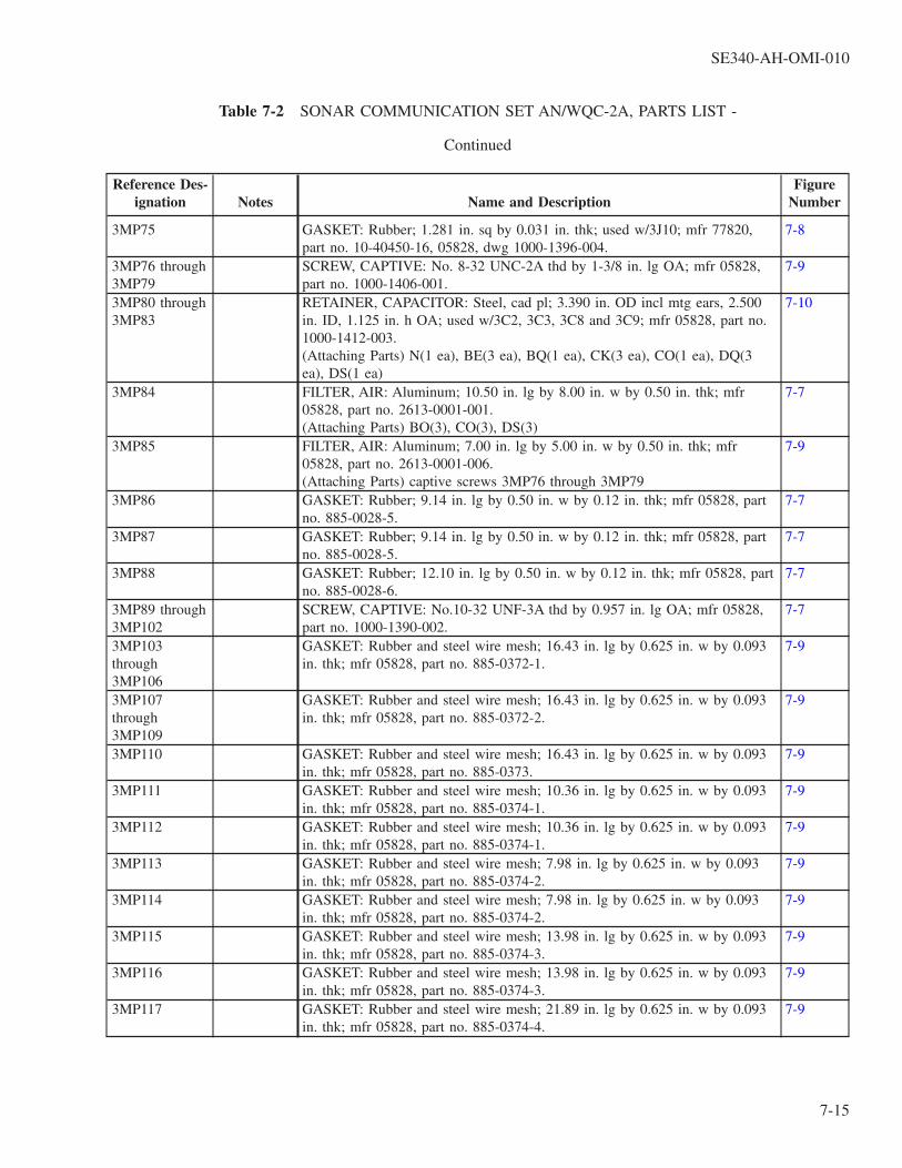
Table 7-2 SONAR COMMUNICATION SET AN/WQC-2A, PARTS LIST -
Continued
Reference Des-ignation Notes Name and Description
FigureNumber
3MP75 GASKET: Rubber; 1.281 in. sq by 0.031 in. thk; used w/3J10; mfr 77820,part no. 10-40450-16, 05828, dwg 1000-1396-004.
7-8
3MP76 through3MP79
SCREW, CAPTIVE: No. 8-32 UNC-2A thd by 1-3/8 in. lg OA; mfr 05828,part no. 1000-1406-001.
7-9
3MP80 through3MP83
RETAINER, CAPACITOR: Steel, cad pl; 3.390 in. OD incl mtg ears, 2.500in. ID, 1.125 in. h OA; used w/3C2, 3C3, 3C8 and 3C9; mfr 05828, part no.1000-1412-003.(Attaching Parts) N(1 ea), BE(3 ea), BQ(1 ea), CK(3 ea), CO(1 ea), DQ(3ea), DS(1 ea)
7-10
3MP84 FILTER, AIR: Aluminum; 10.50 in. lg by 8.00 in. w by 0.50 in. thk; mfr05828, part no. 2613-0001-001.(Attaching Parts) BO(3), CO(3), DS(3)
7-7
3MP85 FILTER, AIR: Aluminum; 7.00 in. lg by 5.00 in. w by 0.50 in. thk; mfr05828, part no. 2613-0001-006.(Attaching Parts) captive screws 3MP76 through 3MP79
7-9
3MP86 GASKET: Rubber; 9.14 in. lg by 0.50 in. w by 0.12 in. thk; mfr 05828, partno. 885-0028-5.
7-7
3MP87 GASKET: Rubber; 9.14 in. lg by 0.50 in. w by 0.12 in. thk; mfr 05828, partno. 885-0028-5.
7-7
3MP88 GASKET: Rubber; 12.10 in. lg by 0.50 in. w by 0.12 in. thk; mfr 05828, partno. 885-0028-6.
7-7
3MP89 through3MP102
SCREW, CAPTIVE: No.10-32 UNF-3A thd by 0.957 in. lg OA; mfr 05828,part no. 1000-1390-002.
7-7
3MP103through3MP106
GASKET: Rubber and steel wire mesh; 16.43 in. lg by 0.625 in. w by 0.093in. thk; mfr 05828, part no. 885-0372-1.
7-9
3MP107through3MP109
GASKET: Rubber and steel wire mesh; 16.43 in. lg by 0.625 in. w by 0.093in. thk; mfr 05828, part no. 885-0372-2.
7-9
3MP110 GASKET: Rubber and steel wire mesh; 16.43 in. lg by 0.625 in. w by 0.093in. thk; mfr 05828, part no. 885-0373.
7-9
3MP111 GASKET: Rubber and steel wire mesh; 10.36 in. lg by 0.625 in. w by 0.093in. thk; mfr 05828, part no. 885-0374-1.
7-9
3MP112 GASKET: Rubber and steel wire mesh; 10.36 in. lg by 0.625 in. w by 0.093in. thk; mfr 05828, part no. 885-0374-1.
7-9
3MP113 GASKET: Rubber and steel wire mesh; 7.98 in. lg by 0.625 in. w by 0.093in. thk; mfr 05828, part no. 885-0374-2.
7-9
3MP114 GASKET: Rubber and steel wire mesh; 7.98 in. lg by 0.625 in. w by 0.093in. thk; mfr 05828, part no. 885-0374-2.
7-9
3MP115 GASKET: Rubber and steel wire mesh; 13.98 in. lg by 0.625 in. w by 0.093in. thk; mfr 05828, part no. 885-0374-3.
7-9
3MP116 GASKET: Rubber and steel wire mesh; 13.98 in. lg by 0.625 in. w by 0.093in. thk; mfr 05828, part no. 885-0374-3.
7-9
3MP117 GASKET: Rubber and steel wire mesh; 21.89 in. lg by 0.625 in. w by 0.093in. thk; mfr 05828, part no. 885-0374-4.
7-9
SE340-AH-OMI-010
7-15

Table 7-2 SONAR COMMUNICATION SET AN/WQC-2A, PARTS LIST -
Continued
Reference Des-ignation Notes Name and Description
FigureNumber
3MP118 GASKET: Rubber and steel wire mesh; 21.89 in. lg by 0. 625 in. w by 0.093in. thk; mfr 05828, part no. 885-0374-4.
7-9
3MP119through3MP122
GASKET: Rubber; 7.06 in. lg by 0.50 in. w by 0.06 in. thk; mfr 05828, partno. 885-0243.
7-9
3MP123through3MP126
GASKET: Rubber; 12.66 in. lg by 0.50 in. w by 0.06 in. thk; mfr 05828, partno. 885-0244.
7-9
3MP127 WHEEL SUPPORT ASSEMBLY: Cad pl steel support channel with 2 in. dianeoprene rubber caster wheel; OA dim. excl wheel 4.70 in. lg by 2.30 in. dby 1.34 in. w; mfr 05828, part no. 885-0206-1.(Attaching Parts) AF(2), CU(2), DV(2)
7-10
3MP128 WHEEL SUPPORT ASSEMBLY: Cad pl steel support channel with 2 in. dianeoprene rubber caster wheel; OA dim. excl wheel 4.70 in. lg by 2.30 in. dby 1.34 in. w; mfr 05828, part no. 885-0206-1.(Attaching Parts) AF(2), CU(2), DV(2)
7-10
3MP129 SUPPORT, ANGLE, RIGHT-HAND: Aluminum alloy angle, 1/4 in. thk; 2.12in. lg by 1.63 in. h incl dowel pin by 1.12 in. w; 1.000 in. spacing betweenmtg holes; mfr 05828, part no. 885-0205-1.(Attaching Parts) AF(2), CU(2), DV(2)
7-10
3MP130 SUPPORT, ANGLE, LEFT-HAND: Aluminum alloy angle, 1/4 in. thk; 2.12in. lg by 1.63 in. h incl dowel pin by 1.12 in. w; 1.250 in. spacing betweenmtg holes; mfr 05828, part no. 885-0208-1.(Attaching Parts) AF(2), CU(2), DV(2)
7-10
3MP131through3MP136
PIN, ECCENTRIC: Steel, cad pl; 1-43/64 in. lg OA, 0.375 in. dia pin shaft;supplied w/bushings to accom 0.177-0.250 in. panel thk; mfr 05828, part no.1000-1407-002.(Attaching Parts) Q(1 ea), CV(1 ea), DV(1 ea)
7-8
3MP137 GASKET: Rubber; 8 in. sq, 7-1/4 in. ID, 1/2 in. thk; mfr 05828, part no. 885-0343.
7-9
3MP138through3MP141
BOLT, EYE: Carbon steel; 3/8-16 UNC-2A thd; MIL type MS51937-3 withcad pl finish; mfr 05828, part no. 885-0296.(Attaching Parts) CZ(1 ea), DW(1 ea)
7-7
3MP142through3MP150
SCREW, CAPTIVE: No. 8-32 UNC-3A thd by 0.810 in. lg OA; mfr 05828,part no. 1000-1423-003.
7-7
3P1 CONNECTOR, RECEPTACLE, ELECTRICAL: 66 female contacts; MILtype M28748/4J60L1A.
7-12 (Sht1)
3P2 Not used.3P3 CONNECTOR, RECEPTACLE, ELECTRICAL: 66 female contacts; MIL
type M28748/4J60L1A.7-17 (Sht1)
3P4 CONNECTOR, RECEPTACLE, ELECTRICAL: 66 female contacts; MILtype M28748/4J60L1A.
7-17 (Sht1)
3P5 CONNECTOR, RECEPTACLE, ELECTRICAL: 34 female contacts; MILtype M28748/4F40L1A.
7-36 (Sht1)
SE340-AH-OMI-010
7-16

Table 7-2 SONAR COMMUNICATION SET AN/WQC-2A, PARTS LIST -
Continued
Reference Des-ignation Notes Name and Description
FigureNumber
3Q1 through3Q6
TRANSISTOR: MIL type 2N2222A. 7-9
3R1 Not Used3R2 RESISTOR, FIXED, WIRE WOUND: 100 ohms ±5%, 26W; MIL type
RW33V101.(Attaching Parts) bracket assy 3MP46
7-9
3R3 SHUNT, INSTRUMENT: 50 mV, 30 A; MIL type MS91586-1.(Attaching Parts) BR(2), CM(2)
7-9
3R4 RESISTOR, FDCED, WIRE WOUND: 150 ohms ±5%, 159W; MIL typeRW38V151.(Attaching Parts) threaded rod 3MP2, mica washer 3MP10, 3MP11, centeringwasher 3MP22, 3MP23, bracket 3MP34, 3MP35
7-9
3R5 through3R9
RESISTOR, FIXED, WIRE WOUND: 8 ohms ±10%, 300W; 8-1/2 in. lg by1-3/8 in. dia; mfr 05828, part no. 4738-0002-001.(Attaching Parts) threaded rod 3MP3-3MP7 (1 ea), mica washer 3MP12-3MP21 (2 ea), centering washer 3MP24-3MP33 (2 ea), bracket 3MP36-3MP45 (2 ea)
7-9
3R10 RESISTOR, FIXED, FILM: 5IK ohms ±5%, 1W; MIL type RL32S513J. 7-103R11 RESISTOR, FIXED, FILM: 1100 ohms ±5%, l/2W; MIL type RL20S112J. 7-103R12 RESISTOR, FIXED, COMPOSITION: 100K ohms ±5%, 2W; MIL type
RC42GF104J.7-9
3R13 RESISTOR, FIXED, COMPOSITION: 100K ohms ±5%, 2W; MIL typeRC42GF104J.
3R14 RESISTOR, FIXED, WIRE WOUND: 0.22 ohms ±10%, 55W; MIL typeRW35VR22. (Attaching Parts) bracket assy 3MP9
7-9
3R15 RESISTOR, FIXED, COMPOSITION: 910 ohms ±5%, 1W; MIL typeRC32GF911J.
7-9
3R16 RESISTOR, FIXED, COMPOSITION: 3000 ohms ±5%, 1/2W; MIL typeRC20GF302J.
7-9
3R17 RESISTOR, FIXED, COMPOSITION: 1500 ohms ±5%, 1W; MIL typeRC32GF152J.
3R18 RESISTOR, FIXED, COMPOSITION: 2000 ohms ±5%, 1/2W; MIL typeRC20GF202J.
7-9
3R19 RESISTOR, FIXED, COMPOSITION: 1500 ohms ±5%, 1W; MIL typeRC32GF152J.
7-9
3R20 RESISTOR, FIXED, COMPOSITION: 750 ohms ±5%, 2W; MIL typeRC42GF751J.
7-9
3R21 Not Used3R22, 3R23,3R24
RESISTOR, FIXED: 175 ohm ±1%, 50W; mfr 91637, part no. RH50-175. 7-9
3RV1 RESISTOR, VOLTAGE SENSITIVE: 150 VDC, 135 VAC continuous operat-ing voltage, 3W max power loss, 5100 watt-sec max discharge capacity; 3 in.dia thyrite disk, 2-1/4 in. lg OA; mfr 05828, part no. 4749-0001-001.(Attaching Parts) DW(1); supplied with one self-locking nut and two hex nutsto fit 3/8-16 thd
7-10
SE340-AH-OMI-010
7-17

Table 7-2 SONAR COMMUNICATION SET AN/WQC-2A, PARTS LIST -
Continued
Reference Des-ignation Notes Name and Description
FigureNumber
3S1 through3S4
SWITCH, SENSITIVE: Interlock, SPDT; MIL type MS16106-1.(Attaching Parts) AK(2 ea), BD(1 ea)
7-9
3T1 TRANSFORMER, POWER, STEP-UP: 115 volts rms, 60 Hz input; 130 voltsrms at 28 amps output, CT; type TF4TX02YY configuration; mfr 05828, partno. 5637-0058-001.(Attaching Parts) AC(4), CZ(4)
7-10
3T2 TRANSFORMER, AUDIO FREQUENCY: pri 1.01 ohms impd, 0.0075 ohmsDCR; sec 40 ohms impd, 0.25 ohms DCR; type TF4TX02YY configuration;mfr 05828, part no. 5608-0020-001.(Attaching Parts) AC(4), CZ(4)
7-10
3TB1 TERMINAL BOARD: 10 stud type terminals; double row; MIL type 8TB10.(Attaching Parts) BR(2), CM(2)
7-9
3TB2 TERMINAL BOARD: 10 stud type terminals; two single rows; MIL type16TB10.(Attaching Parts) BW(2), CQ(2)
7-9
3TB3 TERMINAL BOARD: 10 stud type terminals; two single rows; MIL type16TB10.(Attaching Parts) BW(2), CQ(2)
7-9
3XK1 Not used.3XK2 SOCKET, RELAY: 14 contacts, gold-pl; MIL type MS25328-4 except no
QPL source; mfr 05828, part no. 2155-0004-01.(Attaching Parts) AB(3), AE(3)
7-9
3XK3 SOCKET RELAY: 14 contacts, gold-pl beryllium copper; molded plastic insu-lator body; 1.344 in. lg by 0.390 in. w by 0.281 in. h excl mtg studs; mfr05828, part no. 2155-0003-01.(Attaching Parts) K(2), DE(2)
7-9
3XK5 1 SOCKET, RELAY: 14 contacts, 10 A; MIL type MS24328-2(Attaching Parts) AH(2), J(2), DF(2), CG(2)
7-7
3A1 POWER SUPPLY AND TEST PANEL ASSEMBLY: Drawer chassis w/com-ponents assembled for operation; mfr 05828, part no. 885-0220-2.
7-7
3A1C1 CAPACITOR, FIXED, ELECTROLYTIC: 5600 pF -10%, +75%, 50 VDCW;MIL type CE71C562G.(Attaching Parts) retainer 3A1MP27, 3A1MP28
7-12 (Sht1)
3A1C2 CAPACITOR, FIXED, CERAMIC DIELECTRIC: 0.1 µF ±10%, 100 VDCW;MIL type CK06BX104K.
7-12 (Sht2)
3A1C3 CAPACITOR, FIXED, ELECTROLYTIC: 2700 pF -10%, +75%, 50 VDCW;MIL type CE71C272G.(Attaching Parts) retainer 3A1MP29, 3A1MP30
7-12 (Sht1)
3A1C4 CAPACITOR, FIXED, CERAMIC DIELECTRIC: 0.1 µF ±10%, 100 VDCW;MIL type CK06BX104K.
7-12 (Sht1)
3A1C5 CAPACITOR, FIXED, CERAMIC DIELECTRIC: 1000 pF ±10%, 200VDCW; MIL type CK05BX102K.
7-12 (Sht2)
3A1C6 CAPACITOR, FIXED, CERAMIC DIELECTRIC: 1000 pF ±10%, 200VDCW; MIL type CK05BX102K.
7-13
3A1C7 CAPACITOR, FIXED, CERAMIC DIELECTRIC: 1. 0 µF ±10%, 50 VDCW;MIL type CK06BX105K.
7-12 (Sht2)
SE340-AH-OMI-010
7-18

Table 7-2 SONAR COMMUNICATION SET AN/WQC-2A, PARTS LIST -
Continued
Reference Des-ignation Notes Name and Description
FigureNumber
3A1CB1 CIRCUIT BREAKER: MIL type M55629/3-123.(Attaching Parts) boot 3A1MP8
7-11
3A1CR1through3A1CR8
SEMICONDUCTOR DEVICE, DIODE: Silicon rectifier; mfr 05828, part no.4809-0032-001.(Attaching Parts) D(1 ea), F(2 ea), S(1 ea), CB(1 ea), CU(1 ea)
7-12 (Sht1)
3A1CR9 SEMICONDUCTOR DEVICE, DIODE: MIL type 1N3611. 7-133A1CR10 SEMICONDUCTOR DEVICE, DIODE: Silicon rectifier; mfr 05828, part no.
4809-0032-001.(Attaching Parts) D(1), F(2), S(1), CB(1), CU(1)
7-12 (Sht1)
3A1CR11 SEMICONDUCTOR DEVICE, DIODE: MIL type 1N3611. 7-133A1CR12 SEMICONDUCTOR DEVICE, DIODE: MIL type 1N5533B. 7-12 (Sht
2)3A1CR13 SEMICONDUCTOR DEVICE, DIODE: MIL type 1N5535B. 7-12 (Sht
2)3A1CR14 SEMICONDUCTOR DEVICE, DIODE: MIL type 1N4148. 7-12 (Sht
2)3A1CR15 SEMICONDUCTOR DEVICE, DIODE: MIL type 1N4148. 7-12 (Sht
2)3A1CR16 SEMICONDUCTOR DEVICE, DIODE: MIL type 1N3611. 7-133A1CR17 SEMICONDUCTOR DEVICE, DIODE: Zener, silicon; 500 mW, 6.8V ±5%;
mfr 07263, part no. 1N5235B.7-12 (Sht1)
3A1CR18 SEMICONDUCTOR DEVICE, DIODE: MIL type 1N4148. 7-12 (Sht2)
3A1DS1through3A1DS11
LAMP, INCANDESCENT: Clear T-1-3/4 bulb, midget flanged base; MILtype MS18209-387.
7-11
3A1E1 through3A1E6, 3A1E9
TERMINAL, STUD: mfr 71279, part no. 2034-4-05, 05828, dwg 1000-1404-004.
7-12 (Sht2)
3A1E7 TERMINAL, FEEDTHRU, INSULATED: mfr 98291, part no. 011-2055,05828, dwg 1000-1083-0005.
7-12 (Sht1)
3A1E8 TERMINAL, FEEDTHRU, INSULATED: mfr 98291, part no. 011-2055,05828, dwg 1000-1083-0005.
7-12 (Sht1)
3A1F1 FUSE, CARTRIDGE: 125V, 3A; MIL type F02B125V3A; used w/fuseholder3A1XF1.
7-11
3A1F2 FUSE, CARTRIDGE: 250V, 1A; MIL type F02B250V1A; used w/fuseholder3A1XF1.
7-11
3A1F3 FUSE, CARTRIDGE: 250V, 1A; MIL type F02A250V1A; used w/fuseholder3A1XF3.
7-11
3A1F4 FUSE, CARTRIDGE: 250V, 1A; MIL type F02A250V1A; used w/fuseholder3A1XF3.
7-11
3A1F5 FUSE, CARTRIDGE: 250V, 1A; MIL type F02A250V1A; used w/fuseholder3A1XF5.
7-11
3A1J1 CONNECTOR, RECEPTACLE, ELECTRICAL: 66 male contacts; MIL typeM28748/3J00F1A.(Attaching Parts) J(4), AH(4), CG(4), DO(4)
7-12 (Sht1)
SE340-AH-OMI-010
7-19

Table 7-2 SONAR COMMUNICATION SET AN/WQC-2A, PARTS LIST -
Continued
Reference Des-ignation Notes Name and Description
FigureNumber
3A1J2 CONNECTOR, RECEPTACLE, ELECTRICAL: 66 female contacts; MILtype M28748/4J00F1A.(Attaching Parts) J(4), AH(4), CG(4), DQ(4)
7-12 (Sht1)
3A1J3 JACK, TIP: Red; MIL type M39024/10-02; supplied with internal tooth lockwasher, 13/32 in. OD by 0.20 in. thk, and hex nut, 1/4-32 UNEF-2B thd,11/32 in. across flats by 3/32 in. thk.
7-12 (Sht1)
3A1J4 JACK, TIP: Black; MIL type M39024/10-03; supplied with internal toothlock washer, 13/32 in. OD by 0.20 in. thk, and hex nut, 1/4-32 UNEF-2B thd,11/32 in. across flats by 3/32 in. thk.
7-12 (Sht1)
3A1K1 RELAY, ARMATURE: 4PDT; MIL type M5757/15-001.(Attaching Parts) M(4), CK(4), DQ(4)
7-12 (Sht1)
3A1K2 RELAY, ARMATURE: DPDT; 23-37 VDC coil, 768 ohms DCR nom; maxOA dim. 1.330 in. lg incl mtg ears by 0.900 in. h by 0.400 in. w; mfr 05828,part no. 4522-0010-001.(Attaching Parts) L(2), AX(2), CG(2), DO(2)
7-12 (Sht1)
3A1K3 RELAY, ARMATURE: DPDT; 23-37 VDC coil, 768 ohms DCR nom; maxOA dim. 1330 in. lg incl mtg ears by 0.900 in. h by 0.400 in. w; mfr 05828,part no. 4522-0010-001.(Attaching Parts) L(2), AX(2), CG(2), DO(2)
7-12 (Sht1)
3A1M1 METER, TIME TOTALIZING: Hours and tenths; 115V, 60 Hz; MIL typeMS17325-2.(Attaching Parts) J(2), AW(2), CH(2), DO(2)
7-11
3A1M2 VOLTMETER: Three concentric scales, 0-5 VDC, 0-10 VDC, 0-25 VDC; mfr05828, part no. 2986-0001-001.(Attaching Parts) supplied with 3 ea no. 4-40 UNC-2A RH black screws, hexnuts and lock washers
7-11
3A1M3 AMMETER: 0-30 amps DC; mfr 05828, part no. 2957-0001-001.(Attaching Parts) supplied with 3 ea no. 4-40 UNC-2A RH black screws, hexnuts and lock washers
7-11
3AIMP1 HANDLE, BOW: Brass, black chemical coating; MIL type MS39087-4.(Attaching Parts) B(2), BV(2), CR(2), DU(2)
7-11
3A1MP2 HANDLE, BOW: Brass, black chemical coaling; MIL type MS39087-4.(Attaching Parts) B(2) BV(2), CR(2), DU(2)
7-11
3A1MP3 KNOB, CONTROL: Used w/two no. 8-32 UNC-3A setscrews; MIL typeMS91528-1K2B.
7-12 (Sht1)
3A1MP4 KNOB, CONTROL: Used w/two no. 8-32 UNC-3A setscrews; MIL typeMS91528-2E2B.
7-11
3A1MP5 KNOB, CONTROL: Used w/two no. 8-32 UNC-3A setscrews; MIL typeMS91528-2K2B.
7-11
3A1MP6 BOOT, DUST AND MOISTURE SEAL: Rubber, used W/3A1S1; MIL typeM5423/02-01.
7-11
3A1MP7 BOOT, DUST AND MOISTURE SEAL: Rubber, used W/3A1S4; MIL typeM5423AJ2-01.
7-11
SE340-AH-OMI-010
7-20

Table 7-2 SONAR COMMUNICATION SET AN/WQC-2A, PARTS LIST -
Continued
Reference Des-ignation Notes Name and Description
FigureNumber
3A1MP8 BOOT, DUST AND MOISTURE SEAL: Steel frame w/transparent siliconerubber seal; MIL type M5423/14-06(Attaching Parts) supplied w/four stainless steel pan hd screws, no. 6-32 UNCthd by 038 in. lg, w/silicone O-ring under head
7-11
3A1MP9through3A1MP18
SCREW, CAPTIVE: No. 10-32 UNF-3A thd by 0.957 in. lg OA; mfr 05828,part no. 1000-1390-402.
7-11
3A1MP19 SCREW, CAPTIVE: No. 10-32 UNF-3A thd by 1.207 in. lg OA; mfr 05828,part no. 1000-1390-005.
7-11
3A1MP20 SCREW, CAPTIVE: No. 10-32 UNF-3A thd by 1.207 in. lg OA; mfr 05828,part no. 1000-1390-005.
7-11
3A1MP21 GUARD, SWITCH: Black plastic; 0.91 in. sq by 0.90 in. h; mfr 24446, partno. 2296421P3BLK, 05828, dwg 1000-1402-001.
7-11
3A1MP22 GUARD, SWITCH: Red plastic; 0.91 in. sq by 0.90 in. h; mfr 24446, partno. 2296421P3RED, 05828, dwg 1000-1402-402.
7-11
3A1MP23 PIN, ECCENTRIC: Steel, cad pl; 1.640 in. lg OA, 0375 in. dia pin shaft;supplied w/bushings to accom 0.088-0.125 in. panel thk; mfr 05828, part no.1000-1576-001.(Attaching Parts) Q(1), CT(1), DV(1)
7-11
3A1MP24 PIN, ECCENTRIC: Steel, cad pl; 1.640 in. lg OA, 0375 in. dia pin shaft;supplied w/bushings to accom 0.088-0.125 in. panel thk; mfr 05828, part no.1000-1576-001.(Attaching Parts) Q(1), CT(1), DV(2)
7-11
3A1MP25 BUSHING, MACHINE THREAD; Steel, cad pl; 1/2-20 UNF-3A thd, 0.975in. lg OA by 0.625 in. dia; accom 0.062-0.437 in. panel thk; mfr 05828, partno. 1000-1408-001.(Attaching Parts) AD(1), DA(3)
7-12 (Sht1)
3A1MP26 BUSHING, MACHINE THREAD; Steel, cad pl; 1/2-20 UNF-3A thd, 0.975in. lg OA by 0.625 in. dia; accom 0.062-0.437 is. panel thk; mfr 05828, partno. 1000-1408-001.(Attaching Parts) AD(1), DA(3)
7-12 (Sht1)
3A1MP27 RETAINER, CAPACITOR: Steel, cad pl; 2.875 in. OD incl mtg ears, 2.400in ID, 1.125 in. h OA; used w/3A1C1; mfr 05828, part no. 1000-1412-002.(Attaching Parts) O(1), BE(3), BV(1), CK(3), CR(1), DQ(3), DU(1)
7-12 (Sht1)
3A1MP28 RETAINER, CAPACITOR: Steel, cad pl; 2.875 in. OD incl mtg ears, 2.000in. ID, 1.125 in. h OA; used w/3A1C1; mfr 05828, part no. 1000-1412-002.(Attaching Parts) O(1), BJ(3), BV(1), CK(6), CR(1), DQ(3), DU(1)
7-12 (Sht1)
3A1MP29 RETAINER, CAPACITOR: Steel, cad pl; 2.875 in. OD incl mtg ears, 2.000in. ID, 1.125 in. h OA; used w/3A1C3; mfr 05828, part no. 1000-1412-002.(Attaching Parts) O(1), BE(3), BV(1), CK(3), CR(1), DQ(3), DU(1)
7-12 (Sht1)
3A1MP30 RETAINER, CAPACITOR: Steel, cad pl; 2.875 in. OD incl mtg ears, 2.000in. ID, 1.125 in. h OA; used w/3A1C3; mfr 05828, part no. 1000-1412-002.
7-12 (Sht1)
3A1MP31 HEAT SINK, ELECTRICAL-ELECTRONIC COMPONENT: Two-piece alu-minum; mfr 05828, part no. 1000-1574-001.(Attaching Parts) BWA(2), DBA(2), ADA(2)
7-12 (Sht2)
SE340-AH-OMI-010
7-21

Table 7-2 SONAR COMMUNICATION SET AN/WQC-2A, PARTS LIST -
Continued
Reference Des-ignation Notes Name and Description
FigureNumber
3A1MP32through3A1MP34
HEAT SINK, ELECTRICAL-ELECTRONIC COMPONENT: Aluminum alloyextrusion, black anodized finish; 4.812 in. b max by 3.000 in. w by 1.250 in.d; mfr 05828, part no. 48184005-001.(Attaching Parts) BO(4 ea), CO(4 ea)
7-12 (Sht1)
3A1MP35 GASKET: Rubber, 1.82 in. lg by 0.74 in. w by 0.12 in. thk; mfr 05828, partno. 885-0420-5
7-12 (Sht1)
3A1MP36 GASKET: Rubber, 2.62 in. OD, 2.30 in. ID, 0.06 in. thk; used w/3A1M2; mfr05828, part no. 885-0147.
7-11
3A1MP37 GASKET: Rubber, 2.62 in. OD, 2.20 in. ID, 0.06 in. thk; used w/3A1M3; mfr05828, part no. 885-0147.
7-11
3A1MP38 GASKET: Rubber, 1.46 in. sq, 1.06 in. dia hole size, 0.031 in. thk; usedw/3A1M1, mfr 05828, part no. 885-0148.
7-11
3A1MP39 RETAINER, PCB: Aluminum alloy; 2.58 in. lg by 1.00 in. w by 0.12 in. thk;used w/two steel positive locking studs (part no. 1000-1034-0004); mfr05828, part no. 885-0044-3.
7-12 (Sht1)
3A1MP40 SLIDE, DRAWER, EXTENSION: Steel, cad pl; 13.1 in. lg by 3.25 in. h maxby 0.274 in. w, supplied with 5/16-24 UNF-3A pivot screw; mfr 05828, panno. 1436-0002-001.(Attaching Parts) T(1), BU(6), CR(6), CW(1), DG(1)
7-13
3A1MP41 SLIDE, DRAWER, EXTENSION: Steel, cad pl; 13.1 in. lg by 3.25 in. h maxby 0.274 in. w; supplied with 5/16-24 UNF-3A pivot screw; mfr 05828, partno. 1436-0002-001,(Attaching Parts) T(1), BU(6), CR(6), CW(1), DG(1)
7-13
3A1P1 CONNECTOR, RECEPTACLE, ELECTRICAL: 66 male contacts; MIL typeM28748/3J30L1A.
7-12 (Sht1)
3A1Q1 TRANSISTOR: MIL type JAN2N4405. 7-12 (Sht2)
3A1Q2 TRANSISTOR: MIL type JAN2N3791.(Attaching Parts) BJ(2), DQ(2)
7-12 (Sht1)
3A1Q3 TRANSISTOR: MIL type JAN2N3791.(Attaching Parts) BJ(2), DQ(2)
7-12 (Sht1)
3A1Q4 TRANSISTOR: MIL type JAN2N3902. 7-12 (Sht1)
3A1Q5 TRANSISTOR: MIL type JAN2N3486A. 7-12 (Sht2)
3A1Q6 TRANSISTOR: MIL type JAN2N5114.(Attaching Parts) BK(2), DQ(2)
7-12 (Sht2)
3A1R1 RESISTOR, FIXED, FILM: 1400 OHMS±1%, 1/2 W; MIL typeRLR20C1401FM.
7-12 (Sht2)
3A1R2 RESISTOR, FIXED, WIRE WOUND: 0.22 OHMS ± 1%, 7 W; MIL typeRWR84SR221FM.
7-12 (Sht2)
3A1R3 RESISTOR, FIXED, WIRE WOUND: 0.22 OHMS ± 1%, 7 W; MIL typeRWR84SR221FM.
7-12 (Sht2)
3A1R4 RESISTOR, FIXED, FILM: 95.3K OHMS ± 1%, 1/8 W; MIL typeRN60C9532F.
7-12 (Sht1)
SE340-AH-OMI-010
7-22

Table 7-2 SONAR COMMUNICATION SET AN/WQC-2A, PARTS LIST -
Continued
Reference Des-ignation Notes Name and Description
FigureNumber
3A1R5 RESISTOR, FIXED, WIRE WOUND: 1000 OHMS ±5%, 6.5 W; MIL typeRW67V102.
7-12 (Sht1)
3A1R6 RESISTOR, FIXED, WIRE WOUND: 0.22 OHMS ± 10%, 3 W; MIL typeRW69VR22.
7-12 (Sht1)
3A1R7 RESISTOR, VARIABLE, COMPOSITION: 10K OHMS ± 10%, 2 W; MILtype RV4SAYSD103A.(Attaching Parts) V(1), CY(1), DI(1)
7-11
3A1R8 RESISTOR, FIXED, FILM: 1300 OHMS ± 1%, 1/2 W; MIL typeRLR20C1301FM.
7-12 (Sht2)
3A1R9 RESISTOR, FIXED, FILM: 1620 OHMS ± 1%, 1/8 W; MIL typeRLR05C1621FM.
7-12 (Sht2)
3A1R10 RESISTOR, FIXED, FILM: 1000 OHMS ± 1%, 1/8 W; MIL typeRLR05C1001FM.
7-12 (Sht2)
3A1S1 SWITCH, TOGGLE: Two pole, off-none-on; w/solder term.; MIL typeMS35059-22.(Attaching Parts) Y(1), DC(1), DJ(1)
7-11
3A1S2 SWITCH, ROTARY: 2P4pos; 30 deg angle of throw; plastic insul; 2.061 in. hincl shaft by 1.375 in. d.; mfr 05828, part no. 5147-0014-002.(Attaching Parts) W(1), DH(1)
7-12 (Sht1)
3A1S3 SWITCH, ROTARY: Single pole, 13 positions; 20 deg angle of throw; plasticinsul; 3.810 in. h incl shaft by 1.890 in. d.; mfr 05828, part no. 5147-0015-001.(Attaching Parts) W(1), CY(1), DH(1)
7-11
3A1S4 SWITCH, TOGGLE: Single pole, off-none-on; w/solder term.; MIL typeMS35058-22.(Attaching Parts) Y(1), DC(1), DJ(1)
7-11
3A1T1 TRANSFORMER, POWER, STEP-DOWN: 115 volts rms, 50-60 Hz input,160 VW peak max; 29.9 volts rms (no load) at 6.0 amps DC output, 50 VWpeak max., type TF4RX02NB configuration; mfr 05828, part no. 5637-0056-001.(Attaching Parts) P(4), CT(4), DV(4)
7-12 (Sht1)
3A1T2 TRANSFORMER, POWER, STEP-DOWN: 115 volts rms, 50-60 Hz input,180 VW peak max; 30.4 volts rms (no load) at 2 amps DC output, 100 VWpeak max., type TF4RX02KB configuration; mfr 05828, part no. 5637-0055-001.(Attaching Parts) O(4), CR(4), DU(4)
7-12 (Sht1)
3A1XA1 CONNECTOR, RECEPTACLE, ELECTRICAL: Accom 30 pin contacts max,0.156 in. contact spacing; 3.240 in. lg OA by 0.670 in. h by 0.483 in. w; usedw/two polarizing keys (mfr 53711, part no. 5196055); mfr 05828, part no.2126-0027-001.(Attaching Parts) J(2), AZ(2), CF(4), DO(2)
7-13
3A1XA2 CONNECTOR, RECEPTACLE, ELECTRICAL: Accom 30 pin contacts max,0.156 in. contact spacing; 3.240 in. lg OA by 0.670 in. h by 0.483 in. w; usedw/two polarizing keys (mfr 53711, part no. 5196055); mfr 05828, part no.2126-0027-001.(Attaching Parts) J(2), AZ(2), CF(4), DO(2)
7-13
SE340-AH-OMI-010
7-23

Table 7-2 SONAR COMMUNICATION SET AN/WQC-2A, PARTS LIST -
Continued
Reference Des-ignation Notes Name and Description
FigureNumber
3A1XDS1 LAMPHOLDER: MIL type LH89/1.(Attaching Parts) Y(1), DJ(1)
7-11
3A1XDS1-1 LENS, INDICATOR: Green; MIL type LC37GD2. 7-113A1XDS2 LAMPHOLDER: MIL type LH89/1.
(Attaching Parts) Y(1), DJ(1)7-11
3A1XDS2-1 LENS, INDICATOR: Red; MIL type LC37RD2. 7-113A1XDS3 LAMPHOLDER: MIL type LH89/1.
(Attaching Parts) Y(1), DJ(1)7-11
3A1XDS3-1 LENS, INDICATOR: Clear; MIL type LC37CD2. 7-113A1XDS4 LAMPHOLDER: MIL type LH89/1.
(Attaching Parts) Y(1), DJ(1)7-11
3A1XDS4-1 LENS, INDICATOR: Yellow; MIL type LC37YD2. 7-113A1XDS5 LAMPHOLDER: MIL type LH89/1.
(Attaching Parts) Y(1), DJ(1)7-11
3A1XDS5-1 LENS, INDICATOR: Red; MIL type LC37RD2. 7-113A1XDS6through3A1XDS9
LIGHT, INDICATOR: Brass, Ni pl, black; lamp shield incl clear plastic filter;1 - 11/16 in. lg OA excl lamp by 7/16 in. OD; mfr 05828, part no. 3919-0005-002.(Attaching Parts) X(1 ea), CD(1 ea), DK(1 ea)
7-11
3A1XDS10 LAMPHOLDER: MIL type LH89/1.(Attaching Parts) Y(1), DJ(1)
7-11
3A1XDS10-1 LENS, INDICATOR: Blue; MIL type LC37BD2. 7-113A1XDS11 LAMPHOLDER: MIL type LH89/1.
(Attaching Parts) Y(1), DJ(1)7-11
3A1XDS11-1 LENS, INDICATOR: Yellow; MIL type LC37YD2. 7-113A1XF1 FUSEHOLDER, EXTRACTOR POST: MIL type FL10U; used w/fuses
3A1F1 and 3A1F2.(Attaching Parts) BM(2), CL(2), DR(2)
7-11
3A1XF2 Not used.3A1XF3 FUSEHOLDER, EXTRACTOR POST: MIL type FL10U; used w/fuses
3A1F3 and 3A1F4.(Attaching Parts) BM(2), CL(2), DR(2)
7-11
3A1XF4 Not used.3A1XF5 FUSEHOLDER, EXTRACTOR POST: MIL type FL10U; used w/fuses
3A1F5 and spare fuse.(Attaching Parts) BM(2), CL(2), DR(2)
7-11
3A1XF spare FUSEHOLDER, BLOCK: Accom 4 spare fuses; MIL type FH23HM.(Attaching Parts) M(2), BL(2), CK(2), CL(2), DQ(2)
7-13
3A1XQ1 Not used.3A1XQ2through3A1XQ4
SOCKET, ELECTRONIC COMPONENT: Two contacts, gold-pl berylliumcopper; molded plastic insulator body; 1.570 in. lg by 0.730 in. w max by0.350 in. h excl contacts; mfr 05828, part no. 2157-0006-001.(Attaching Parts) L(1), AJ(1), DO(1)
7-12 (Sht1)
3A1A1 REGULATED POWER SUPPLY, +28 VDC: PWB w/components assembledfor operation; mfr 05828, part no. 885-0100-1.
7-12 (Sht1)
SE340-AH-OMI-010
7-24

Table 7-2 SONAR COMMUNICATION SET AN/WQC-2A, PARTS LIST -
Continued
Reference Des-ignation Notes Name and Description
FigureNumber
3A1A1C1 CAPACITOR, FIXED, CERAMIC DIELECTRIC: 1000 pF ± 10%, 200VDCW; MIL type CK05BX102K.
7-14
3A1A1C2 CAPACITOR, FIXED, ELECTROLYTIC: Tantalum; 22 uF ± 10%, 50VDCW; MIL type CS13BG226K.
7-14
3A1A1C3 CAPACITOR, FIXED, ELECTROLYTIC: Tantalum; 22 uF ±10%, 50VDCW; MIL type CS13BG226K.
7-14
3A1A1CR1 SEMICONDUCTOR DEVICE, DIODE: Zener, silicon, voltage regulator;36V, 5W; MIL type JAN1N4971.
7-14
3A1A1MP1 PAD, COMPONENT: Plastic; 0. 500 in. OD by 0.150 in. thk; mfr 07047, partno. 10050DAP, 05828, dwg 1000-1013-0005.
7-14
3A1A1MP2 PAD, COMPONENT: Plastic; 0. 350 in. OD by 0.021 in. thk; mfr 07047, partno. 10007DAP, 05828, dwg 1000-1013-0007.
7-14
3A1A1Q1 TRANSISTOR: MIL type 2N1711. 7-143A1A1R1 RESISTOR, FIXED, WIRE WOUND: 200 ohm, 1%, 1W, MIL type
RWR81S2000FM.7-14
3A1A1R2 RESISTOR, FDCED, FILM: 30K ohms ±2%, 1/4W; MIL type RL07S303G. 7-143A1A1R3 RESISTOR, VARIABLE, WIRE WOUND: 5000 ohms ±5%, 3/4W; MIL type
RT22C2P502.7-14
3A1A1R4 RESISTOR, FIXED, FILM: 9100 ohms ±2%, 1/4W; MIL type RL07S912G. 7-143A1A1U1 MICROCIRCUIT, LINEAR: Regulator; mfr 05828, part no. 4827-0119-001. 7-143A1A2 METER AND MUTING CIRCUIT: PWB w/components assembled for
operation; mfr 05828, part no. 885-0037-1.7-12 (Sht1)
3A1A2C1 CAPACITOR, FIXED, ELECTROLYTIC: Tantalum; 1.5 uF ±10%, 35VDCW; MIL type CS13BF155K.
7-15
3A1A2C2 CAPACITOR, FIXED, ELECTROLYTIC: Tantalum; 10 uF ±10%, 35VDCW; MIL type CS13BF106K.
7-15
3A1A2C3 CAPACITOR FIXED, ELECTROLYTIC: Tantalum; 4.7 uF ±10%, 50VDCW; MIL type CS13BG475K.
7-15
3A1A2C4 CAPACITOR, FIXED, ELECTROLYTIC: Tantalum; 47 uF ±10%, 6 VDCW;MIL type CS13BB476K.
7-15
3A1A2C5 CAPACITOR, FIXED, ELECTROLYTIC: Tantalum; 10 uF ±10%, 35VDCW; MIL type CS13BF106K.
7-15
3A1A2C6 CAPACITOR, FIXED, METALLIZED PAPER DIELECTRIC: 6.8 uF ±10%,50 VDCW; MIL type CH09A1RA685K.
7-15
3A1A2C7 CAPACITOR, FIXED, CERAMIC DIELECTRIC: 470 pF ±10%, 200VDCW; MIL type CK05BX471K.
7-15
3A1A2C8 CAPACITOR, FIXED, CERAMIC DIELECTRIC: 22 pF ±10%, 200 VDCW;MIL type CK05BX220K.
7-15
3A1A2CR1 SEMICONDUCTOR DEVICE, DIODE: MIL type 1N914. 7-153A1A2CR2 SEMICONDUCTOR DEVICE, DIODE: MIL type 1N914. 7-153A1A2CR3 SEMICONDUCTOR DEVICE, DIODE: MIL type 1N750A. 7-153A1A2CR4 SEMICONDUCTOR DEVICE, DIODE: MIL type 1N750A. 7-153A1A2CR5 SEMICONDUCTOR DEVICE, DIODE: MIL type 1N3611. 7-153A1A2CR6 SEMICONDUCTOR DEVICE, DIODE: MIL type 1N914. 7-153A1A2CR7 SEMICONDUCTOR DEVICE, DIODE: MIL type 1N914. 7-15
SE340-AH-OMI-010
7-25

Table 7-2 SONAR COMMUNICATION SET AN/WQC-2A, PARTS LIST -
Continued
Reference Des-ignation Notes Name and Description
FigureNumber
3A1A2J1 JACK, TIP: Accom 0.080 in. dia test probe; yellow teflon body; mfr 98291,part no. 026-4003-234, 05828, dwg 2163-0010-005.
7-15
3A1A2J2 JACK, TIP: Accom 0.080 in. dia test probe; yellow teflon body; mfr 98291,part no. 026-4003-234, 05828, dwg 2163-0010-005.
7-15
3A1A2J3 JACK, TIP: Accom 0.080 in. dia test probe; green teflon body; mfr 98291,part no. 026-4003-235, 05828, dwg 2163-0010-006.
7-15
3A1A2J4 JACK, TIP: Accom 0.080 in. dia test probe; green teflon body, mfr 98291,part no. 026-4003-235, 05828, dwg 2163-0010-006.
7-15
3A1A2MP1through3A1A2MP4
PAD, COMPONENT: Plastic; 0. 350 in. OD by 0.021 in. thk; mfr 07047, partno. 10007DAP, 05828, dwg 1000-1013-0007.
7-15
3A1A2MP5 PAD, COMPONENT: Plastic; 0. 430 in. OD by 0.125 in. thk; mfr 07047, partno. 10277DAP, 05828, dwg 1000-1013-0008.
7-15
3A1A2MP6 HEAT SINK, ELECTRICAL-ELECTRONIC COMPONENT 1.062 in. OD by0.375 in. thk, w/teflon insert; mfr 05828, part no. 4818-0001-001.(Attaching Parts) AR(2), CG(2), DO(2)
7-15
3A1A2Q1 TRANSISTOR: MIL type 2N1485. 7-153A1A2Q2 TRANSISTOR: MIL type 2N1711. 7-153A1A2Q3 TRANSISTOR: MIL type 2N491A. 7-153A1A2Q4 TRANSISTOR: MIL type 2N1711. 7-153A1A2Q5 TRANSISTOR: MIL type 2N1711. 7-153A1A2R1 RESISTOR, FIXED, FILM: 95.3K ohms ±1%, 1/8W; MIL type
RN60C9532F.7-15
3A1A2R2 RESISTOR, FIXED, COMPOSITION: 1500 ohms ±5%, 1/4W; MIL typeRC07GF152J.
7-15
3A1A2R3 RESISTOR, FIXED, FILM: 45.3K ohms ±1%, 1/10W; MIL typeRN55C4532F.
7-15
3A1A2R4 Not used.3A1A2R5 RESISTOR, FIXED, FILM: 499K ohms ±1%, 1/8W; MIL type RN60C4993F. 7-153A1A2R6 RESISTOR, FIXED, FILM: 49.9K ohms ±1%, 1/10W; MIL type
RN55C4992F.7-15
3A1A2R7 RESISTOR, FIXED, FILM: 1.02M ohms ±1%, 1/2W; MIL typeRN65D1024F.
7-15
3A1A2R8 RESISTOR, FIXED, FILM: 499K ohms ±1%, 1/8W; MIL type RN60C4993F. 7-153A1A2R9 RESISTOR, FIXED, COMPOSITION: 10 ohms ±5%, 1/4W; MIL type
RC07GF100J.7-15
3A1A2R10 RESISTOR, FIXED, FILM: 1.02M ohms ±1%, 1/2W; MIL typeRN65D1024F.
7-15
3A1A2R11 RESISTOR, FIXED, COMPOSITION: 10K ohms ±5%, 1/4W; MIL typeRC07GF103J.
7-15
3A1A2R12 RESISTOR, FIXED, FILM: 1M ohms ±1%, 1/4W; MIL type RN65C1004F. 7-153A1A2R13 RESISTOR, FIXED, COMPOSITION: 10K ohms ±5%, 1/4W; MIL type
RC07GF103J.7-15
3A1A2R14 RESISTOR, FIXED, COMPOSITION: 16 ohms ±5%, 1/4W; MIL typeRC07GF160J.
7-15
SE340-AH-OMI-010
7-26

Table 7-2 SONAR COMMUNICATION SET AN/WQC-2A, PARTS LIST -
Continued
Reference Des-ignation Notes Name and Description
FigureNumber
3A1A2R15 RESISTOR, FIXED, COMPOSITION: 22K ohms ±5%, 1/4W; MIL typeRC07GF223J.
7-15
3A1A2R16 RESISTOR, FIXED, FILM: 1960 ohms ±1%, 1/10W; MIL typeRN55C1961F.
7-15
3A1A2R17 RESISTOR, FIXED, WIRE WOUND: 4.75 ohms ±1%, 2W; MIL typeRWR80S4R75FR.
7-15
3A1A2R18 RESISTOR, FIXED, COMPOSITION: 100 ohms ±5%, 1/4W; MIL typeRC07GF101J.
7-15
3A1A2R19 RESISTOR, FIXED, FILM: 620 ohms ±5%, 2W; MIL type RL42S621J. 7-153A1A2R20 RESISTOR, FIXED, FILM: 2000 ohms ±5%, 1/4W; MIL type RL07S202J. 7-153A1A2R21 RESISTOR, FIXED, FILM: 2000 ohms ±5%, 1/4W; MIL type RL07S202J. 7-153A1A2R22 RESISTOR, VARIABLE, NONWIRE WOUND: 2.5M ohms, 1/2W; mfr
05828, part no. 4707-0030-001.7-15
3A1A2R23 RESISTOR, FIXED, FILM: 1000 OHMS ± 5%, 1/4 W; MIL typeRL07S102J.
7-15
3A1A2R24 RESISTOR, FIXED, FILM: 2000 OHMS ± 5%, 1/4 W; MIL typeRL07S202J.
7-15
3A1A2R25 RESISTOR, FIXED, FILM: 100 OHMS ±5%, 1/4 W; MIL type RL07S101J. 7-153A1A2R26 RESISTOR, FIXED, FILM: 2000 OHMS ± 5%, 1/4 W; MIL type
RL07S202J.7-15
3A1A2R27 RESISTOR, FIXED, FILM: 510 OHMS ±5%, 1/4 W; MIL type RL07S511J. 7-153A1A2R28 RESISTOR, FIXED, COMPOSITION: 68 OHMS ± 5%, 1/4 W; MIL type
RC07GF680J.7-15
3A1A2R29 RESISTOR, FIXED, FILM: 680 OHMS ± 5%, 1/4 W; MIL type RL07S681J. 7-153A1A2R30 RESISTOR, FIXED, FILM: 3000 OHMS ± 5%, 1/4 W; MIL type
RL07S302J.7-15
3A1A2R31 RESISTOR, FIXED, FILM: 3000 OHMS ±5%, 1/4 W; MIL type RL07S302J. 7-153A1A2U1 MICROCIRCUIT, LINEAR: Operational Amplifier; mfr 05828, part no.
4827-0058-05.7-15
3A1A2U2 MICROCIRCUIT, DIGITAL: Quad 2-Input NAND Gate; mfr 05828, part no.4827-0121-001.
7-15
3A2 RECEIVER-TRANSMITTER ASSEMBLY: Drawer chassis w/componentsassembled for operation; mfr 05828, part no. 885-0210-2.
7-7
3A2C1 CAPACITOR, VARIABLE, AIR DIELECTRIC: 9 to 143 pF, 500 VDCW;MIL type CT12E143J.(Attaching Parts) AS(2), CG(2), DO(2)
7-17 (Sht2)
3A2C2 CAPACITOR, VARIABLE, AIR DIELECTRIC: 9 to 143 pF, 500 VDCW;MIL type CT12E143J.(Attaching Parts) AS(2), BZ(1), CG(2), DO(2)
7-17 (Sht2)
3A2C3 CAPACITOR, FIXED, ELECTROLYTIC: 2150 uF -10%, + 100%, 25VDCW; mfr 05828, part no. 1506-0004-001.
7-17 (Sht1)
3A2C4 CAPACITOR, FIXED, ELECTROLYTIC: Tantalum; 100 uF + 50%, - 15%,50 VDCW; MIL type CL21BJ101TPE.
7-17 (Sht1)
3A2C5 CAPACITOR, FIXED, ELECTROLYTIC: Tantalum; 10 uF ± 10%, 35VDCW; MIL type CS13BF106K.
7-18
SE340-AH-OMI-010
7-27

Table 7-2 SONAR COMMUNICATION SET AN/WQC-2A, PARTS LIST -
Continued
Reference Des-ignation Notes Name and Description
FigureNumber
3A2C6 CAPACITOR, FIXED, ELECTROLYTIC: Tantalum; 100 uF + 50%, - 15%,50 VDCW; MIL type CL21BJ101TPE.
7-18
3A2C7 through3A2C9
CAPACITOR, FIXED, ELECTROLYTIC: Tantalum; 22 uF ± 10%, 35VDCW; MIL type CS13BF226K.
7-18
3A2C10 CAPACITOR, FIXED, CERAMIC DIELECTRIC: 1.0 uF ± 10%, 50 VDCW;MIL type CK06BX105K.
7-18
3A2C11 CAPACITOR, FIXED, CERAMIC DIELECTRIC: 0.47 uF ± 10%, 50VDCW; MIL type CK06BX474K.
7-18
3A2C12 CAPACITOR, FIXED, CERAMIC DIELECTRIC: 0.015 uF ± 10%, 50VDCW; MIL type M39014/01-1458 (CKR05BX153K).
7-18
3A2CR1through3A2CR13
SEMICONDUCTOR DEVICE, DIODE: MIL type 1N4148. 7-18
3A2CR14 SEMICONDUCTOR DEVICE, DIODE: MIL type 1N3611. 7-183A2E1 Not used.3A2E2 TERMINAL, STUD: MIL type SE076B02. 7-17 (Sht
2)3A2E3 TERMINAL, STUD: Brass, electro-solder plate finish; molded plastic insula-
tor body; 0.594 in. lg OA, 0.250 in. across flats; no. 4-40 UNC-2B thd insert;mfr 71279, part no. 4826-1-0516, 05828, dwg 1000-1380-001.
7-18
3A2E4 TERMINAL: For reference only (contact 3A2K3-A1). 7-183A2E5 TERMINAL: For reference only (contact 3A2K9-D3). 7-183A2E6 TERMINAL, LUG: Phosphor Bronze, tin finish; no. 8 hole size; MIL type
MS77068-3.7-18
3A2E7 TERMINAL PLATE, GROUND: Copper, hot tin finish; 1 - 9/16 in. lg inclmtg ears by 5/8 in. h by 7/16 in. w; mfr 05828, part no. 885-0266.(Attaching Parts) M(2), CK(2), DQ(2)
7-18
3A2E8 TERMINAL PLATE, GROUND: For reference only; same point as 3A2E7. 7-183A2E9 TERMINAL, LUG: Phosphor Bronze, tin finish; no. 8 hole size; MIL type
MS77068-3.7-18
3A2E10 Not used.3A2E11 TERMINAL PLATE, GROUND: For reference only; same point as 3A2E7. 7-183A2E12 TERMINAL: For reference only; same point as 3A2E9. 7-183A2E13 TERMINAL, LUG: Copper, tin finish; 0.153 in. dia hole size; MIL type
MS35431-4.7-18
3A2E14 TERMINAL, LUG: Copper, tin finish; 0.153 in. dia hole size; MIL typeMS35431-4.
7-18
3A2FL1 FILTER, BAND PASS: 250 kHz center frequency; 3 - 3/4 in. lg by 13/16 in.dia body dim; mfr 05828, part no. 2703-0013-001.
7-17 (Sht2)
3A2FL2 FILTER, BAND PASS: Audio; 8 to 11.1 kHz frequency response; 600 ohmsimpd; type FR4RX22AH configuration; mfr 05828, part no. 2703-0014-001.(Attaching Parts) M(2), CK(2), DQ(2)
7-17 (Sht2)
3A2FL3 FILTER, BAND PASS: Audio; 200 Hz to 3.1 kHz frequency response; 1000ohms impd; type FR4RX22AH configuration; mfr 05828, part no. 2703-0014-002.(Attaching Parts) M(2), CK(2), DQ(2)
7-17 (Sht2)
SE340-AH-OMI-010
7-28

Table 7-2 SONAR COMMUNICATION SET AN/WQC-2A, PARTS LIST -
Continued
Reference Des-ignation Notes Name and Description
FigureNumber
3A2J1 CONNECTOR, RECEPTACLE, ELECTRICAL: 66 male contacts; MIL typeM28748/3J00F1A.(Attaching Parts) J(4), AH(4), CG(4), DO(4)
7-17 (Sht1)
3A2J2 CONNECTOR, RECEPTACLE, ELECTRICAL: 66 male contacts; MIL typeM28748/3J00F1A.(Attaching Parts) J(4), AH(4), CG(4), DO(4)
7-17 (Sht1)
3A2K1 RELAY, ARMATURE: 4PDT; MIL type M5757/18-001.(Attaching Parts) M(4), CK(4), DQ(4)
7-17 (Sht2)
3A2K2 RELAY, ARMATURE: 2PDT; MIL type MS25321-D2.(Attaching Parts) AT(2), DO(2)
7-17 (Sht2)
3A2K3 RELAY, ARMATURE: 4PDT; MIL type M5757/7-001.(Attaching Parts) AT(2), CG(2)
7-18
3A2K4 RELAY, ARMATURE: 6PDT; MIL type M5757/1-103.(Attaching Parts) AT(2), CG(2)
7-18
3A2K5 RELAY, ARMATURE: 6PDT; MIL type M5757/1-103.(Attaching Parts) AT(2), CG(2)
7-18
3A2K6 RELAY, ARMATURE: 6PDT; MIL type M5757/16-001.(Attaching Parts) M(4), CK(4), DQ(4)
7-17 (Sht2)
3A2K7 RELAY, ARMATURE: 4PDT; MIL type M5757/18-001.(Attaching Parts) M(4), CK(4), DQ(4)
7-17 (Sht2)
3A2K8 RELAY, ARMATURE: 4PDT; MIL type M5757/18-001.(Attaching Parts) G(1), M(4), CK(4), DQ(4)
7-17 (Sht2)
3A2K9 RELAY, ARMATURE: 6PDT; MIL type M5757/1-103.(Attaching Parts) AT(2), CG(2)
7-18
3A2K10 RELAY, ARMATURE: 4PDT; 26.0 VDC, 75 mA max coil; max OA dim.1.300 in. lg incl mtg ears by 1.00 in. h by 0.400 in. w; mfr 05828, part no.4522-0011-001.(Attaching Parts) AG(2), DD(2)
7-17 (Sht2)
3A2K11 RELAY, ARMATURE: 4PDT; 26.0 VDC, 75 mA max coil; max OA dim.1.300 in. lg incl mtg ears by 1.00 in. h by 0.400 in. w; mfr 05828, part no.4522-0011-001.(Attaching Parts) AG(2), DD(2)
7-17 (Sht2)
3A2K12 RELAY, ARMATURE: 4PDT; MIL type M5757/18-001.(Attaching Parts) M(4), CK(4), DQ(4)
7-17 (Sht2)
3A2K13through3A2K15
RELAY, ARMATURE: DPDT; 23-37 VDC coil; 768 ohms DCR nom; maxOA dim. 1.330 in. lg incl mtg ears by 0.900 in. h by 0.400 in. w; mfr 05828,part no. 4522-0010-001.(Attaching Parts) L(2 ea), AV(2 ea), CG(2 ea), DO(2 ea)
7-17 (Sht2)
3A2MP1 GROMMET, RUBBER: MIL type MS35489-93. 7-17 (Sht2)
3A2MP2 HANDLE, BOW: Brass, black chemical coating; MIL type MS39087-4.(Attaching Parts) B(2), BU(2), CR(2), DU(2)
7-16
3A2MP3 HANDLE, BOW: Brass, black chemical coating; MIL type MS39087-4.(Attaching Parts) B(2), BU(2), CR(2), DU(2)
7-16
SE340-AH-OMI-010
7-29

Table 7-2 SONAR COMMUNICATION SET AN/WQC-2A, PARTS LIST -
Continued
Reference Des-ignation Notes Name and Description
FigureNumber
3A2MP4through3A2MP11
SCREW, CAPTIVE: No. 10-32 UNF-3A thd by 0.957 in. lg OA; mfr 05828,part no. 1000-1390-002.
7-16
3A2MP12through3A2MP17
SCREW, CAPTIVE: No. 6-32 UNC-3A thd by 0.587 in. lg OA; mfr 05828,part no. 1000-1390-003.
7-17 (Sht1)
3A2MP18 SCREW, CAPTIVE: No. 10-32 UNF-3A thd by 1.207 in. lg OA; mfr 05828,part no. 1000-1390-005.
7-16
3A2MP19 SCREW, CAPTIVE: No. 10-32 UNF-3A thd by 1.207 in. lg OA; mfr 05828,part no. 1000-1390-005.
7-16
3A2MP20 PIN, ECCENTRIC: Steel, cad pl; 1.640 in. lg OA, 0.375 in. dia pin shaft;supplied w/bushings to accom 0.088-0.125 in. panel thk; mfr 05828, part no.1000-1576-001.(Attaching Parts) Q(1), CT(1), DV(1)
7-16
3A2MP21 PIN, ECCENTRIC: Steel, cad pl; 1.640 in. lg OA, 0.375 in. dia pin shaft;supplied w/bushings to accom 0.088-0.125 in. panel thk; mfr 05828, part no.1000-1576-001.(Attaching Parts) Q(1), CT(1), DV(1)
7-16
3A2MP22 RECEPTACLE, MODIFIED: Steel, cad pl; 1/2-20 UNF-3A thd, 0.975 in. lgOA by 0.625 in. dia; accom 0.59 in. panel thk; mfr 05828, part no. 885-0329.(Attaching Parts) AD(1), DB(3)
7-17 (Sht1)
3A2MP23 RECEPTACLE, MODIFIED: Steel, cad pl; 1/2-20 UNF-3A thd, 0.975 in. lgOA by 0.625 in. dia; accom 0.59 in. panel thk; mfr 05828, part no. 885-0329.(Attaching Parts) AD(1), DB(3)
7-17 (Sht1)
3A2MP24 GASKET: Rubber; 7.70 in. lg by 1.00 in. w by 0.25 in. thk; mfr 05828, partno. 885-0420-3,
7-17 (Sht1)
3A2MP25 GASKET: Rubber; 0.50 in. lg by 0.44 in. w by 0.18 in. thk; mfr 05828, partno. 885-0025-6.
7-17 (Sht1)
3A2MP26 GASKET: Rubber; 0.50 in. lg by 0.44 in. w by 0.18 in. thk; mfr 05828, partno. 885-0025-6.
7-17 (Sht1)
3A2MP27 GASKET: Rubber; 3.74 in. lg by 0. 50 in. w by 0.12 in. thk; mfr 05828, partno. 885-0025-7.
7-17 (Sht1)
3A2MP28 GROMMET, RUBBER: MIL type MS35489-93. 7-17 (Sht2)
3A2MP29 SLIDE, DRAWER, EXTENSION: Steel, cad pl; 13.1 in. lg by 3.25 in. h maxby 0.274 in. w; supplied with 5/16-24 UNF-3A pivot screw; mfr 05828, partno. 1436-0002-001.(Attaching Parts) T(1), BT(6), CR(6), CW(1), DG(1)
7-17 (Sht1)
3A2MP30 SLIDE, DRAWER, EXTENSION: Steel, cad pl; 13.1 in. lg by 3.25 in. h maxby 0.274 in. w; supplied with 5/16-24 UNF-3A pivot screw; mfr 05828, partno. 1436-0002-001.(Attaching Parts) T(1), BT(6), CR(6), CW(1), DG(1)
7-17 (Sht1)
3A2MP31 GASKET: Rubber; 7.70 in. lg by 1.00 in. w by 0.25 in. thk; mfr 05828, partno. 885-0420-3.
7-17 (Sht1)
SE340-AH-OMI-010
7-30

Table 7-2 SONAR COMMUNICATION SET AN/WQC-2A, PARTS LIST -
Continued
Reference Des-ignation Notes Name and Description
FigureNumber
3A2MP32 RETAINER, PCB: Steel, cad pl; 9.52 in. lg by 1.50 in. w by 0.074 in. thk;used w/one steel fastener stud (part no. 1000-1392-001); mfr 05828, part no.885-0043-2.
7-17 (Sht1)
3A2MP33 RETAINER, PCB: Steel, cad pl; 9.52 in. lg by 1.50 in. w by 0.074 in. thk;used w/one steel fastener stud (part no. 1000-1392-001); mfr 05828, part no.885-0043-2.
7-17 (Sht1)
3A2MP34 GROMMET, RUBBER: MIL type MS35489-35. 7-17 (Sht1)
3A2Q1 TRANSISTOR: MIL type 2N1490.(Attaching Parts) BJ(2), CK(2), DQ(2)
7-17 (Sht1)
3A2Q2 TRANSISTOR: PNP, silicon, high power; mfr 05828, part no. 4822-0021-001.(Attaching Parts) BJ(2), CK(2), DQ(2)
7-17 (Sht1)
3A2R1 RESISTOR, FIXED, FILM: 36K ohms ±5%, 1/2W; MIL type RL20S363J. 7-17 (Sht2)
3A2R2 RESISTOR, FIXED, COMPOSITION: 10 ohms ±5%, 1W; MIL typeRC32GF100J.
7-17 (Sht1)
3A2R3 RESISTOR, FIXED, COMPOSITION: 51 ohms ±5%, 1/2W; MIL typeRC20GF510J.
7-17 (Sht1)
3A2R4 RESISTOR, FIXED, COMPOSITION: 51 ohms ±5%, 1/2W; MIL typeRC20GF510J.
7-17 (Sht1)
3A2R5 RESISTOR, FIXED, COMPOSITION: 100 ohms ±5%, 1/4W; MIL typeRC07GF101J.
7-18
3A2R6 RESISTOR, FIXED, COMPOSITION: 39 ohms ±5%, 1/4W; MIL typeRC07GF390J.
7-18
3A2R7 through3A2R10
RESISTOR, FIXED, COMPOSITION: 10K ohms ±5%, 1/4W; MIL typeRC07GF103J.
7-18
3A2R11 RESISTOR, FIXED, FILM: 15 OHMS ± 5%, 1/2 W; MIL type RL20S150J. 7-183A2R12 RESISTOR, FIXED, FILM: 102K OHMS ± 1%, 1/8 W; MIL type
RN60C1023F.7-18
3A2R13 RESISTOR, VARIABLE, NONWIRE WOUND: 20K OHMS, 3/4 W; MILtype RJR12CL203R.(Attaching Parts) H(2), AQ(2), CE(4), DN(2)
7-18
3A2R14 RESISTOR, VARIABLE, NONWIRE WOUND: 5000 OHMS, 3/4 W; MILtype RJR12CL502R.(Attaching Parts) H(2), AQ(2), CE(4), DN(2)
7-18
3A2R15 RESISTOR, FIXED, COMPOSITION: 1200 OHMS ± 5%, 1/4 W; MIL typeRC07GF122J.
7-18
3A2R16 RESISTOR, FIXED, FILM: 3010 OHMS ± 1%, 1/4 W; MIL typeRN60D3011F.
7-18
3A2R17 RESISTOR, FIXED, FILM: 12.1K OHMS ± 1%, 1/4 W; MIL typeRN60D1212F.
7-18
3A2S1 SWITCH, TOGGLE: Single pole, off-none-on; w/solder term.; MIL typeMS35058-22.(Attaching Parts) Y(2), DC(1), DJ(1)
7-17 (Sht1)
3A2T1 Not used.
SE340-AH-OMI-010
7-31
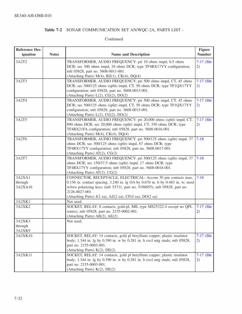
Table 7-2 SONAR COMMUNICATION SET AN/WQC-2A, PARTS LIST -
Continued
Reference Des-ignation Notes Name and Description
FigureNumber
3A2T2 TRANSFORMER, AUDIO FREQUENCY: pri 10 ohms impd, 0.5 ohmsDCR; sec 300 ohms impd, 10 ohms DCR; type TF4RX17YY configuration;mfr 05828, part no. 5608-0011-001.(Attaching Parts) M(4), BZ(1), CK(4), DQ(4)
7-17 (Sht2)
3A2T3 TRANSFORMER, AUDIO FREQUENCY: pri 500 ohms impd, CT, 45 ohmsDCR; sec 500/125 ohms (split) impd, CT, 50 ohms DCR; type TF1QX17YYconfiguration; mfr 05828, part no. 5608-0015-001.(Attaching Parts) L(2), CG(2), DO(2)
7-17 (Sht2)
3A2T4 TRANSFORMER, AUDIO FREQUENCY: pri 500 ohms impd, CT, 45 ohmsDCR; sec 500/125 ohms (split) impd, CT, 50 ohms DCR; type TF1QX17YYconfiguration; mfr 05828, part no. 5608-0015-001.(Attaching Parts) L(2), CG(2), DO(2)
7-17 (Sht2)
3A2T5 TRANSFORMER, AUDIO FREQUENCY: pri 20,000 ohms (split) impd, CT,890 ohms DCR; sec 20,000 ohms (split) impd, CT, 350 ohms DCR; typeTF4RX21FA configuration; mfr 05828, part no. 5608-0016-001.(Attaching Parts) M(4), CK(4), DQ(4)
7-17 (Sht2)
3A2T6 TRANSFORMER, AUDIO FREQUENCY: pri 500/125 ohms (split) impd, 37ohms DCR; sec 500/125 ohms (split) impd, 67 ohms DCR; typeTF4RX17YY configuration; mfr 05828, part no. 5608-0017-001.(Attaching Parts) AT(2), CG(2)
7-18
3A2T7 TRANSFORMER, AUDIO FREQUENCY: pri 500/125 ohms (split) impd, 37ohms DCR; sec 150/37.5 ohms (split) impd, 17 ohms DCR; typeTF4RX17YY configuration; mfr 05828, part no. 5608-0018-001.(Attaching Parts) AT(2), CG(2)
7-18
3A2XA1through3A2XA16
CONNECTOR, RECEPTACLE, ELECTRICAL: Accom 30 pin contacts max,0.156 in. contact spacing; 3.240 in. lg OA by 0.670 in. h by 0.483 in. w; usedw/two polarizing keys (mfr 53711, part no. 5196055); mfr 05828, part no.2126-0027-001.(Attaching Parts) J(2 ea), AZ(2 ea), CF(4 ea), DO(2 ea)
7-18
3A2XK1 Not used.3A2XK2 SOCKET, RELAY: 8 contacts, gold-pl; MIL type MS25322-4 except no QPL
source; mfr 05828, part no. 2155-0002-001.(Attaching Parts) AB(2), AE(2)
7-17 (Sht2)
3A2XK3through3A2XK9
Not used.
3A2XK10 SOCKET, RELAY: 14 contacts, gold pl beryllium copper; plastic insulatorbody; 1.344 in. lg by 0.390 in. w by 0.281 in. h excl mtg studs; mfr 05828,part no. 2155-0003-001.(Attaching Parts) K(2), DE(2)
7-17 (Sht2)
3A2XK11 SOCKET, RELAY: 14 contacts, gold pl beryllium copper; plastic insulatorbody; 1.344 in. lg by 0.390 in. w by 0.281 in. h excl mtg studs; mfr 05828,part no. 2155-0003-001.(Attaching Parts) K(2), DE(2)
7-17 (Sht2)
SE340-AH-OMI-010
7-32

Table 7-2 SONAR COMMUNICATION SET AN/WQC-2A, PARTS LIST -
Continued
Reference Des-ignation Notes Name and Description
FigureNumber
3A2XQ1 SOCKET, ELECTRONIC COMPONENT: Two contacts, gold-pl berylliumcopper; molded plastic insulator body; 1.570 in. lg by 0.730 in. w max by0.350 in. h excl contacts; mfr 05828, part no. 2157-0006-001.(Attaching Parts) L(1), AI(1), CG(1), DO(1)
7-17 (Sht1)
3A2XQ2 SOCKET, ELECTRONIC COMPONENT: Two contacts, gold-pl berylliumcopper; molded plastic insulator body; 1.570 in. lg by 0.730 in. w max by0.350 in. h excl contacts; mfr 05828, part no. 2157-0006-001.(Attaching Parts) L(1), AI(1), CG(1), DO(1)
7-17 (Sht1)
3A2A1 SPEAKER AMPLIFIER: PWB w/components assembled for operation; mfr05828, part no. 885-0350-1.
7-17 (Sht2)
3A2A1C1 CAPACITOR, FIXED, CERAMIC DIELECTRIC: 10 pF ± 10%, 200 VDCW;MIL type CK05BX100K.
7-19
3A2A1C2 CAPACITOR, FIXED, CERAMIC DIELECTRIC: 1000 pF ± 10%, 200VDCW; MIL type CK05BX102K.
7-19
3A2A1C3 CAPACITOR, FIXED, ELECTROLYTIC: Tantalum; 22 uF ± 10%, 35VDCW; MIL type CS13BF226K.
7-19
3A2A1C4 CAPACITOR, FIXED, CERAMIC DIELECTRIC: 27 pF ± 10%, 200 VDCW;MIL type CK05BX270K.
7-19
3A2A1C5 Not Used.3A2A1C6 CAPACITOR, FIXED, ELECTROLYTIC: Tantalum; 22 uF ± 10%, 35
VDCW; MIL type CS13BF226K.7-19
3A2A1C7 CAPACITOR, FIXED, CERAMIC DIELECTRIC: 0.1 uF ± 10%, 100VDCW; MIL type CK06BX104K.
7-19
3A2A1C8 CAPACITOR, FIXED, CERAMIC DIELECTRIC: 120 pF ± 10%, 200VDCW; MIL type CK05BX121K.
7-19
3A2A1C9 CAPACITOR, FIXED, ELECTROLYTIC: Tantalum; 22 uF ± 10%, 35VDCW; MIL type CS13BF226K.
7-19
3A2A1C10 CAPACITOR, FIXED, CERAMIC DIELECTRIC: 270 pF ± 10%, 200VDCW; MIL type CK05BX271K.
7-19
3A2A1C11 CAPACITOR, FIXED, ELECTROLYTIC: Tantalum; 6.8 uF ± 10%, 6VDCW; MIL type CS13BB685K.
7-19
3A2A1C12 CAPACITOR, FIXED, ELECTROLYTIC: Tantalum; 6.8 uF ± 10%, 6VDCW; MIL type CS13BB685K.
7-19
3A2A1C13 CAPACITOR, FIXED, CERAMIC DIELECTRIC: 0.1 uF ± 10%, 100VDCW; MIL type CK06BX104K.
7-19
3A2A1CR1 SEMICONDUCTOR DEVICE, DIODE: MIL type 1N914. 7-193A2A1CR2 SEMICONDUCTOR DEVICE, DIODE: MIL type 1N914. 7-193A2A1CR3 SEMICONDUCTOR DEVICE, DIODE: Zener, silicon, voltage regulator; mfr
05828, part no. 4812-0021-007.7-19
3A2A1CR4 SEMICONDUCTOR DEVICE, DIODE: Zener, silicon, voltage regulator; mfr05828, part no. 4812-0021-007.
7-19
3A2A1CR5 SEMICONDUCTOR DEVICE, DIODE: MIL type 1N3611. 7-193A2A1CR6 SEMICONDUCTOR DEVICE, DIODE: MIL type 1N914. 7-193A2A1CR7 SEMICONDUCTOR DEVICE, DIODE: MIL type 1N914. 7-19
SE340-AH-OMI-010
7-33

Table 7-2 SONAR COMMUNICATION SET AN/WQC-2A, PARTS LIST -
Continued
Reference Des-ignation Notes Name and Description
FigureNumber
3A2A1CR8through3A2A1CR13
SEMICONDUCTOR DEVICE, DIODE: MIL type 1N3611. 7-19
3A2A1J1 JACK, TIP: Accom 0.080 in. dia test probe; yellow teflon body, mfr 98291,part no. 026-4003-234, 05828, dwg 2163-0010-005.
7-19
3A2A1J2 JACK, TIP: Accom 0.080 in. dia test probe; green teflon body, mfr 98291,part no. 026-4003-235, 05828, dwg 2163-0010-006.
7-19
3A2A1J3 JACK, TIP: Accom 0.080 in. dia test probe; green teflon body, mfr 98291,part no. 026-4003-235, 05828, dwg 2163-0010-006.
7-19
3A2A1J4 JACK, TIP: Accom 0.080 in. dia test probe; black teflon body, mfr 98291,part no. 026-4003-230, 05828, dwg 2163-0010-001.
7-19
3A2A1J5 JACK, TIP: Accom 0.080 in. dia test probe; red teflon body, mfr 98291, partno. 026-4003-232, 05828, dwg 2163-0010-003.
7-19
3A2A1K1 RELAY, ARMATURE: DPDT; MIL type M5757/9-004. 7-193A2A1MP1 PAD, COMPONENT: Plastic; 0.305 in. OD by 0.125 in. thk; mfr 07047, part
no. 10033DAP, 05828, dwg 1000-1013-0001.7-19
3A2A1MP2 PAD, COMPONENT: Plastic; 0.305 in. OD by 0.125 in. thk; mfr 07047, partno. 10033DAP, 05828, dwg 1000-1013-0001.
7-19
3A2A1MP3 PAD, COMPONENT: Plastic; 0.430 in. OD by 0.125 in. thk; mfr 07047, partno. 10277DAP, 05828, dwg 1000-1013-0008.
7-19
3A2A1MP4 PAD, COMPONENT: Plastic; 0.430 in. OD by 0.125 in. thk; mfr 07047, partno. 10277DAP, 05828, dwg 1000-1013-0008.
7-19
3A2A1Q1 TRANSISTOR: MIL type 2N1711. 7-193A2A1Q2 TRANSISTOR: MIL type 2N2905. 7-193A2A1R1 RESISTOR, FIXED, COMPOSITION: 1500 OHMS ± 5%, 1/4 W; MIL type
RC07GF152J.7-19
3A2A1R2 RESISTOR, FIXED, FILM: 30.1K OHMS ± 1%, 1/10 W; MIL typeRN55C3012F.
7-19
3A2A1R3 RESISTOR, FIXED, FILM: 15K OHMS ± 1%, 1/10 W; MIL typeRN55C1502F.
7-19
3A2A1R4 RESISTOR, FIXED, FILM: 562K OHMS ± 1%, 1/10 W; MIL typeRNR55C5623FS.
7-19
3A2A1R5 RESISTOR, VARIABLE, NONWIRE WOUND: 25K OHMS, 1/2 W; MILtype RJ22CP253.
7-19
3A2A1R6 RESISTOR, FIXED, FILM: 1500 OHMS ± 1%, 1/10 W; MIL typeRN55C1501F.
7-19
3A2A1R7 RESISTOR, FIXED, FILM: 332K OHMS ± 1%, 1/10 W; MIL typeRNR55C3323FS.
7-19
3A2A1R8 RESISTOR, FIXED, FILM: 4320 OHMS ± 1%, 1/10 W; MIL typeRN55C4321F.
7-19
3A2A1R9 RESISTOR, FIXED, FILM: 4750 OHMS ± 1%, 1/8 W; MIL typeRN55D4751F.
7-19
3A2A1R10 RESISTOR, FIXED, FILM: 4750 OHMS ± 1%, 1/8 W; MIL typeRN55D4751F.
7-19
3A2A1R11 RESISTOR, FIXED, COMPOSITION: 1500 OHMS ± 5%, 1/4 W; MIL typeRC07GF152J.
7-19
SE340-AH-OMI-010
7-34

Table 7-2 SONAR COMMUNICATION SET AN/WQC-2A, PARTS LIST -
Continued
Reference Des-ignation Notes Name and Description
FigureNumber
3A2A1R12 RESISTOR, FIXED, COMPOSITION: 12K OHMS ± 5%, 1/4 W; MIL typeRC07GF123J.
7-19
3A2A1R13 RESISTOR, FIXED, COMPOSITION: 12K OHMS ± 5%, 1/4 W; MIL typeRC07GF123J.
7-19
3A2A1U1 MICROCIRCUIT, LINEAR: Operational Amplifier; mfr 05828, part no.4827-0058-05.
7-19
3A2A1U2 MICROCIRCUIT, LINEAR: Operational Amplifier; mfr 05828, part no.4827-0058-05.
7-19
3A2A2 DRIVER AMPLIFIER AND LF EQUALIZER: PWB w/componentsassembled for operation; mfr 05828, part no. 885-0060-1.
7-17 (Sht2)
3A2A2C1 CAPACITOR, FIXED, ELECTROLYTIC: Tantalum; 0.39 uF ± 10%, 35VDCW; MIL type CS13BF394K.
7-20
3A2A2C2 CAPACITOR, FIXED, ELECTROLYTIC: Tantalum; 10 uF ± 10%, 20VDCW; MIL type CS13BE106K.
7-20
3A2A2C3 CAPACITOR, FIXED, ELECTROLYTIC: Tantalum; 10 uF ± 10%, 50VDCW; MIL type CS13BG106K.
7-20
3A2A2C4 CAPACITOR, FIXED, MICA DIELECTRIC: 680 pF ± 5%, 500 VDCW;MIL type CM06FD681J03.
7-20
3A2A2C5 CAPACITOR, FIXED, ELECTROLYTIC: Tantalum; 1.5 uF ± 10%, 20VDCW; MIL type CS13BE155K.
7-20
3A2A2C6 CAPACITOR, FIXED, ELECTROLYTIC: Tantalum; 10 uF ± 10%, 20VDCW; MIL type CS13BE106K.
7-20
3A2A2C7 CAPACITOR, FIXED, ELECTROLYTIC: Tantalum; 10 uF ± 10%, 50VDCW; MIL type CS13BG106K.
7-20
3A2A2C8 CAPACITOR, FIXED, ELECTROLYTIC: Tantalum; 10 uF ± 10%, 20VDCW; MIL type CS13BE106K.
7-20
3A2A2C9 CAPACITOR, FIXED, ELECTROLYTIC: Tantalum; 10 uF ± 10%, 50VDCW; MIL type CS13BG106K.
7-20
3A2A2C10 CAPACITOR, FIXED, ELECTROLYTIC: Tantalum; 1.0 uF ± 10%, 35VDCW; MIL type CS13BF105K.
7-20
3A2A2C11 CAPACITOR, FIXED, PLASTIC DIELECTRIC: 0.018 uF ± 5%, 50 VDCW;MIL type CFR04RSA183JM.
7-20
3A2A2C12 CAPACITOR, FIXED, PLASTIC DIELECTRIC: 0.015 uF ± 5%, 50 VDCW;MIL type CFR04RSA153JM.
7-20
3A2A2C13 CAPACITOR, FIXED, PLASTIC DIELECTRIC: 0.1 uF ± 5%, 50 VDCW;MIL type CFR04RSA104JM.
7-20
3A2A2C14 CAPACITOR, FIXED, PLASTIC DIELECTRIC: 0.1 uF ± 5%, 50 VDCW;MIL type CFR04RSA104JM.
7-20
3A2A2C15 CAPACITOR, FIXED, PLASTIC DIELECTRIC: 8200 pF ± 5%, 50 VDCW;MIL type CFR04RSA822JM.
7-20
3A2A2C16 CAPACITOR, FIXED, ELECTROLYTIC: Tantalum; 1.0 uF ± 10%, 35VDCW; MIL type CS13BF105K.
7-20
3A2A2C17 CAPACITOR, FIXED, PLASTIC DIELECTRIC: 3900 pF ± 5%, 50 VDCW;MIL type CFR04RSA392JM.
7-20
3A2A2C18 CAPACITOR, FIXED, PLASTIC DIELECTRIC: 4700 pF ± 5%, 50 VDCW;MIL type CFR04RSA472JM.
7-20
SE340-AH-OMI-010
7-35

Table 7-2 SONAR COMMUNICATION SET AN/WQC-2A, PARTS LIST -
Continued
Reference Des-ignation Notes Name and Description
FigureNumber
3A2A2C19 CAPACITOR, FIXED, PLASTIC DIELECTRIC: 0.01 uF ± 5%, 50 VDCW;MIL type CFR04RSA103JM.
7-20
3A2A2C20 CAPACITOR, FIXED, ELECTROLYTIC: Tantalum; 1.0 uF ± 10%, 35VDCW; MIL type CS13BF105K.
7-20
3A2A2C21 CAPACITOR, FIXED, CERAMIC DIELECTRIC: 1000 pF ± 10%, 200VDCW; MIL type CK05BX102K.
7-20
3A2A2J1 JACK, TIP: Accom 0.080 in. dia test probe; yellow teflon body, mfr 98291,part no. 026-4003-234, 05828, dwg 2163-0010-005.
7-20
3A2A2J2 JACK, TIP: Accom 0.080 in. dia test probe; green teflon body; mfr 98291,part no. 026-4003-235, 05828, dwg 2163-0010-006.
7-20
3A2A2J3 JACK, TIP: Accom 0.080 in. dia test probe; black teflon body; mfr 98291,part no. 026-4003-230, 05828, dwg 2163-0010-001.
7-20
3A2A2J4 JACK, TIP: Accom 0.080 in. dia test probe; green teflon body; mfr 98291,part no. 026-4003-235, 05828, dwg 2163-0010-006.
7-20
3A2A2L1 REACTOR: Audio inductor; 0.08 H ±3% at 4 mA, 23 ohms ±10% DCR;type TF5RX20ZZ configuration; mfr 05828, part no. 1800-0002-001.(Attaching Parts) L(1), BB(1), CG(2), DO(1)
7-20
3A2A2L2 REACTOR: Audio inductor; 0.08 H ±3% at 4 mA, 23 ohms ±10% DCR;type TF5RX20ZZ configuration; mfr 05828, part no. 1800-0002-001.(Attaching Parts) L(1), BB(1), CG(2), DO(1)
7-20
3A2A2MP1through3A2A2MP6
PAD, COMPONENT: Plastic; 0.305 in. OD by 0.125 in. thk; mfr 07047, partno. 10033 DAP, 05828, dwg 1000-1013-0001.
7-20
3A2A2MP7through3A2A2MP9
PAD, COMPONENT: Plastic; 0.350 in. OD by 0.021 in. thk; mfr 07047, partno. 10007DAP, 05828, dwg 1000-1013-0007.
7-20
3A2A2Q1through3A2A2Q3
TRANSISTOR: MIL type 2N1711. 7-20
3A2A2Q4through3A2A2Q9
TRANSISTOR: MIL type 2N2222A. 7-20
3A2A2R1 RESISTOR, FIXED, FILM: 68K ohms ±5%, 1/2W; MIL type RL20S683J. 7-203A2A2R2 RESISTOR, FIXED, FILM: 10K ohms ±5%, 1/2W; MIL type RL20S103J. 7-203A2A2R3 RESISTOR, FIXED, FILM: 750 ohms ±5%, 1/2W; MIL type RL20S751J. 7-203A2A2R4 RESISTOR, FIXED, FILM: 5620 ohms ±1%, 1/4W; MIL type RN60D5621F. 7-203A2A2R5 RESISTOR, FIXED, FILM: 20K ohms ±5%, 1/2W; MIL type RL20S203J. 7-203A2A2R6 RESISTOR, FIXED, FILM: 510 ohms ±5%, 1/2W; MIL type RL20S511J. 7-203A2A2R7 RESISTOR, FIXED, FILM: 7500 ohms ±5%, 1/2W; MIL type RL20S752J. 7-203A2A2R8 RESISTOR, FIXED, FILM: 200 ohms ±5%, 1/2W; MIL type RL20S201J. 7-203A2A2R9 RESISTOR, FIXED, FILM: 2000 ohms ±5%, 1/2W; MIL type RL20S202J. 7-203A2A2R10 RESISTOR, FIXED, FILM: 200 ohms ±5%, 1/2W; MIL type RL20S201J. 7-203A2A2R11 RESISTOR, FIXED, FILM: 300 ohms ±5%, 1W; MIL type RL32S301J. 7-203A2A2R12 RESISTOR, FIXED, FILM: 100K ohms ±2%, 1/4W; MIL type RL07S104G. 7-203A2A2R13 RESISTOR, FIXED, FILM: 100K ohms ±2%, 1/4W; MIL type RL07S104G. 7-20
SE340-AH-OMI-010
7-36

Table 7-2 SONAR COMMUNICATION SET AN/WQC-2A, PARTS LIST -
Continued
Reference Des-ignation Notes Name and Description
FigureNumber
3A2A2R14 RESISTOR, FIXED, FILM: 120 ohms ±2%, 1/4W; MIL type RL07S121G. 7-203A2A2R15 RESISTOR, FIXED, FILM: 2000 ohms ±2%, 1/4W; MIL type RL07S202G. 7-203A2A2R16 RESISTOR, FIXED, COMPOSITION: 10K ohms ±5%, 1/4W; MIL type
RC07GF103J.7-20
3A2A2R17 RESISTOR, FIXED, COMPOSITION: 10K ohms ±5%, 1/4W; MIL typeRC07GF103J.
7-20
3A2A2R18 RESISTOR, FIXED, COMPOSITION: 1000 ohms ±5%, 1/4W; MIL typeRC07GF102J.
7-20
3A2A2R19 RESISTOR, FIXED, FILM: 33 ohms ±2%, 1/2W; MIL type RL20S330G. 7-203A2A2R20 RESISTOR, FIXED, COMPOSITION: 10K ohms ±5%, 1/4W; MIL type
RC07GF103J.7-20
3A2A2R21 RESISTOR, FIXED, COMPOSITION: 10K ohms ±5%, 1/4W; MIL typeRC07GF103J.
7-20
3A2A2R22 RESISTOR, FIXED, COMPOSITION: 120 ohms ±5%, 1/4W; MIL typeRC07GF121J.
7-20
3A2A2R23 RESISTOR, FIXED, COMPOSITION: 1500 ohms ±5%, 1/4W; MIL typeRC07GF152J.
7-20
3A2A2R24 RESISTOR, FIXED, FILM: 3600 ohms ±2%, 1/4W; MIL type RL07S362G. 7-203A2A2R25 RESISTOR, FIXED, COMPOSITION: 100K ohms ±5%, 1/4W; MIL type
RC07GF104J.7-20
3A2A2R26 RESISTOR, FIXED, FILM: 3900 ohms ±2%, 1/4W; MIL type RL07S392G. 7-203A2A2R27 RESISTOR, FIXED, FILM: 100K ohms ±2%, 1/4W; MIL type RL07S104G. 7-203A2A2R28 RESISTOR, FIXED, FILM: 100K ohms ±2%, 1/4W; MIL type RL07S104G. 7-203A2A2R29 RESISTOR, FIXED, COMPOSITION: 100 ohms ±5%, 1/4W; MIL type
RC07GF101J.7-20
3A2A2R30 RESISTOR, FIXED, COMPOSITION: 10K ohms ±5%, 1/4W; MIL typeRC07GF103J.
7-20
3A2A2R31 RESISTOR, FIXED, COMPOSITION: 100 ohms ±5%, 1/4W; MIL typeRC07GF101J.
7-20
3A2A2R32 RESISTOR, FIXED, COMPOSITION: 10K ohms ±5%, 1/4W; MIL typeRC07GF103J.
7-20
3A2A3 EQUALIZER AMPLIFIER: PWB w/components assembled for operation;mfr 05828, part no. 885-0330-1.
7-17 (Sht2)
3A2A3C1 CAPACITOR, FIXED, CERAMIC DIELECTRIC: 0.1 uF ±10%, 100 VDCW;MIL type CK06BX104K.
7-21
3A2A3C2 CAPACITOR, FIXED, MICA DIELECTRIC: 0.082 uF ±5%, 100 VDCW;MIL type CM08FA823J03.
7-21
3A2A3C3 CAPACITOR, FIXED, MICA DIELECTRIC: 4700 pF ±5%, 500 VDCW;MIL type CM06FD472J03.
7-21
3A2A3C4 CAPACITOR, FIXED, MICA DIELECTRIC: 9100 pF ±1%, 500 VDCW;MIL type CM07FD912F03.
7-21
3A2A3C5 CAPACITOR, FIXED, MICA DIELECTRIC: 9100 pF ±5%, 500 VDCW;MIL type CM07FD912J03.
7-21
3A2A3C6 CAPACITOR, FIXED, ELECTROLYTIC: Tantalum; 18 uF ±10%, 50VDCW; MIL type CS13BG186K.
7-21
SE340-AH-OMI-010
7-37

Table 7-2 SONAR COMMUNICATION SET AN/WQC-2A, PARTS LIST -
Continued
Reference Des-ignation Notes Name and Description
FigureNumber
3A2A3C7 CAPACITOR, FIXED, ELECTROLYTIC: Tantalum; 1.0 uF ±10%, 35VDCW; MIL type CS13BF105K.
7-21
3A2A3J1 JACK, TIP: Accom 0.080 in. dia test probe; red teflon body; mfr 98291, partno. 026-4003-232, 05828, dwg 2163-0010-003.
7-21
3A2A3J2 JACK, TIP: Accom 0.080 in. dia test probe; green teflon body; mfr 98291,part no. 026-4003-235, 05828, dwg 2163-0010-006.
7-21
3A2A3J3 JACK, TIP: Accom 0.080 in. dia test probe; green teflon body; mfr 98291,part no. 026-4003-235, 05828, dwg 2163-0010-006.
7-21
3A2A3J4 JACK, TIP: Accom 0.080 in. dia test probe; black teflon body; mfr 98291,part no. 026-4003-230, 05828, dwg 2163-0010-001.
7-21
3A2A3MP1 PAD, COMPONENT: Plastic; 0.305 in. OD by 0.125 in. thk; mfr 07047, partno. 10033DAP, 05828, dwg 1000-1013-0001.
7-21
3A2A3MP2 PAD, COMPONENT: Plastic; 0.350 in. OD by 0.021 in. thk; mfr 07047, partno. 10007DAP, 05828, dwg 1000-1013-0007.
7-21
3A2A3MP3 PAD, COMPONENT: Plastic, 0.350 in. OD by 0.021 in. thk; mfr 07047, partno. 10007DAP, 05828, dwg 1000-1013-0007.
7-21
3A2A3Q1 TRANSISTOR: MIL type 2N2222A. 7-213A2A3Q2 TRANSISTOR: MIL type 2N1711. 7-213A2A3Q3 TRANSISTOR: MIL type 2N1711. 7-213A2A3R1 RESISTOR, FIXED, COMPOSITION: 240 ohms ±5%, 1/4W; MIL type
RC07GF241J.7-21
3A2A3R2 RESISTOR, FIXED, COMPOSITION: 1000 ohms ±5%, 1/4W; MIL typeRC07GF102J.
7-21
3A2A3R3 RESISTOR, FIXED, COMPOSITION: 100K ohms ±5%, 1/4W; MIL typeRC07GF104J.
7-21
3A2A3R4 RESISTOR, FIXED, COMPOSITION: 100K ohms ±5%, 1/4W; MIL typeRC07GF104J.
7-21
3A2A3R5 RESISTOR, FIXED, FILM: 11K ohms ±1%, 1/10W; MIL type RN55C1102F. 7-213A2A3R6 RESISTOR, FIXED, FILM: 825 ohms ±1%, 1/10W; MIL type RN55C8250F. 7-213A2A3R7 RESISTOR, FIXED, COMPOSITION: 15K ohms ±5%, 1/4W; MIL type
RC07GF153J.7-21
3A2A3R8 RESISTOR, FIXED, COMPOSITION: 1000 ohms ±5%, 1/4W; MIL typeRC07GF102J.
7-21
3A2A3R9 RESISTOR, FIXED, FILM: 3920 ohms ±1%, 1/10W; MIL typeRN55C3921F.
7-21
3A2A3R10 RESISTOR, FIXED, FILM: 100K ohms ±1%, 1/10W; MIL typeRN55C1003F.
7-21
3A2A3R11 RESISTOR, FIXED, FILM: 100K ohms ±1%, 1/10W; MIL typeRN55C1003F.
7-21
3A2A3R12 RESISTOR, FIXED, COMPOSITION: 5100 ohms ±5%, 1/4W; MIL typeRC07GF512J.
7-21
3A2A3R13 RESISTOR, FIXED, COMPOSITION: 15K ohms ±5%, 1/4W; MIL typeRC07GF153J.
7-21
3A2A4 TEST OSCILLATOR: PWB w/components assembled for operation; mfr05828, part no. 885-0355-1.
7-17 (Sht2)
SE340-AH-OMI-010
7-38

Table 7-2 SONAR COMMUNICATION SET AN/WQC-2A, PARTS LIST -
Continued
Reference Des-ignation Notes Name and Description
FigureNumber
3A2A4C1 CAPACITOR, FIXED, ELECTROLYTIC: Tantalum, 10 uF ±10%, 50 VDCW,MIL type CS13BG106K.
7-22
3A2A4C2 CAPACITOR, FIXED, METALLIZED PAPER DIELECTRIC: 0.82 uF ±5%,50 VDCW; MIL type CH09A1RA824J.
7-22
3A2A4C3 CAPACITOR, FIXED, METALLIZED PAPER DIELECTRIC: 0.082 uF ±5%,50 VDCW; MIL type CH09A1RA823J.
7-22
3A2A4C4 CAPACITOR, FIXED, ELECTROLYTIC: Tantalum; 10 uF ±10%, 20VDCW; MIL type CS13BE106K.
7-22
3A2A4C5 CAPACITOR, FIXED, ELECTROLYTIC: Tantalum; 10 uF ±10%, 50 VDCW,MIL type CS13BG106K.
7-22
3A2A4C6 CAPACITOR, FIXED, METALLIZED PAPER DIELECTRIC: 0.039 uF ±5%,50 VDCW; MIL type CH09A1RA393J.
7-22
3A2A4C7 CAPACITOR, FIXED, PLASTIC DIELECTRIC: 3900 pF ±5%, 200 VDCW;MIL type CQ09A1KC392J3.
7-22
3A2A4C8 CAPACITOR, FIXED, ELECTROLYTIC: Tantalum; 10 uF ±10%, 20VDCW; MIL type CS13BE106K.
7-22
3A2A4J1 JACK, TIP: Accom 0.080 in. dia test probe; red teflon body; infr 98291, partno. 026-4003-232, 05828, dwg 2163-0010-003.
7-22
3A2A4J2 JACK, TIP: Accom 0.080 in. dia test probe; red teflon body; mfr 98291, partno. 026-4003-232, 05828, dwg 2163-0010-003.
7-22
3A2A4J3 JACK, TIP: Accom 0.080 in. dia test probe; black teflon body; mfr 98291,part no. 026-4003-230, 05828, dwg 2163-0010-001.
7-22
3A2A4L1 REACTOR: Audio inductor; 0.08 H ±3% at 4 mA, 23 ohms ±10% DCR;type TF5RX20ZZ configuration; mfr 05828, part no. 1800-0002-001.(Attaching Parts) L(1), BB(1), CG(2), DO(1)
7-22
3A2A4L2 REACTOR: Audio inductor; 0.08 H ±3% at 4 mA, 23 ohms ±10% DCR;type TF5RX20ZZ configuration; mfr 05828, part no. 1800-0002-001.(Attaching Parts) L(1), BB(1), CG(2), DO(1)
7-22
3A2A4MP1 PAD, COMPONENT: Plastic; 0.350 in. OD by 0.021 in. thk; mfr 07047, partno. 10007DAP, 05828, dwg 1000-1013-0007.
7-22
3A2A4MP2 PAD, COMPONENT: Plastic; 0.350 in. OD by 0.021 in. thk; mfr 07047, partno. 10007DAP, 05828, dwg 1000-1013-0007.
7-22
3A2A4Q1 TRANSISTOR: MIL type 2N1711. 7-223A2A4Q2 TRANSISTOR: MIL type 2N1711. 7-223A2A4R1 RESISTOR, FIXED, FILM: 8200 ohms ±5%, 1/2W; MIL type RL20S822J. 7-223A2A4R2 RESISTOR, FIXED, FILM: 110K ohms ±5%, 1/2W; MIL type RL20S114J. 7-223A2A4R3 RESISTOR, FIXED, FILM: 51K ohms ±5%, 1/2W; RL20S513J. 7-223A2A4R4 RESISTOR, FIXED, FILM: 5100 ohms ±5%, 1/2W; MIL type RL20S512J. 7-223A2A4R5 RESISTOR, FIXED, FILM: 10K ohms ±5%, 1/2W; MIL type RL20S103J. 7-223A2A4R6 RESISTOR, FIXED, FILM: 8200 ohms ±5%, 1/2W; MIL type RL20S822J. 7-223A2A4R7 RESISTOR, FIXED, FILM: 56K ohms ±5%, 1/2W; MIL type RL20S563J. 7-223A2A4R8 RESISTOR, FIXED, FILM: 10K ohms ±5%, 1/2W; MIL type RL20S103J. 7-223A2A4R9 RESISTOR, FIXED, FILM: 47K ohms ±5%, 1/2W; MIL type RL20S473J. 7-223A2A4R10 RESISTOR, FIXED, FILM: 12K ohms ±2%, 1/2W; MIL type RL20S123G. 7-22
SE340-AH-OMI-010
7-39

Table 7-2 SONAR COMMUNICATION SET AN/WQC-2A, PARTS LIST -
Continued
Reference Des-ignation Notes Name and Description
FigureNumber
3A2A4R11 RESISTOR, FIXED, COMPOSITION: 10 ohms ±5%, 1/2W; MIL typeRC20GF100J.
7-22
3A2A4R12 RESISTOR, FIXED, FILM: 100 ohms ±5%, 1/2W; MIL type RL20S101J. 7-223A2A4R13 RESISTOR, FIXED, FILM: 169 ohms ±1%, 1/10W; MIL type RN55C1690F. 7-223A2A4R14 RESISTOR, FIXED, FILM: 2150 ohms ±1%, 1/10W; MIL type
RN55C2151F.7-22
3A2A4R15 RESISTOR, FIXED, FILM: 12.4 ohms ±1%, 1/10W; MIL typeRN55C12R4F.
7-22
3A2A4S1 SWITCH, TOGGLE: SPDT, off-none-on; 1.090 in. lg OA by 0.500 in. w by0.370 in. d incl term.; mfr 05828, part no. 5160-0005-001.
7-22
3A2A4S2 SWITCH, TOGGLE: SPDT, off-none-on; 1.090 in. lg OA by 0.500 in. w by0.370 in. d incl term.; mfr 05828, part no. 5160-0005-001.
7-22
3A2A5 LOW PASS FILTER: PWB w/components assembled for operation; mfr05828, part no. 885-0110-1.
7-17 (Sht2)
3A2A5C1 CAPACITOR, FIXED, ELECTROLYTIC: Tantalum; 22 uF ±10%, 50VDCW; MIL type CS13BG226K.
7-23
3A2A5C2 CAPACITOR, FIXED, ELECTROLYTIC: Tantalum; 22 uF ±10%, 35VDCW; MIL type CS13BF226K.
7-23
3A2A5C3 CAPACITOR, FIXED, MICA DIELECTRIC: 0.018 uF ±5%, 500 VDCW;MIL type CM07FD183J03.
7-23
3A2A5C4 CAPACITOR, FIXED, MICA DIELECTRIC: 0.022 uF ±5%, 500 VDCW;MIL type CM08FD223J03.
7-23
3A2A5C5 CAPACITOR, FIXED, ELECTROLYTIC: Tantalum; 22 uF ±10%, 35VDCW; MIL type CS13BF226K.
7-23
3A2A5C6 CAPACITOR, FIXED, ELECTROLYTIC: Tantalum; 10 uF ±10%, 20VDCW; MIL type CS13BE106K.
7-23
3A2A5C7 CAPACITOR, FIXED, ELECTROLYTIC: Tantalum; 150 uF ±10%, 15VDCW; MIL type CS13BD157K.
7-23
3A2A5J1 JACK, TIP: Accom 0.080 in. dia test probe; yellow teflon body; mfr 98291,part no. 026-4003-234, 05828, dwg 2163-0010-005.
7-23
3A2A5J2 JACK, TIP: Accom 0.080 in. dia test probe; green teflon body; mfr 98291,part no. 026-4003-235, 05828, dwg 2163-0010-006.
7-23
3A2A5J3 JACK, TIP: Accom 0.080 in. dia test probe; black teflon body; mfr 98291,part no. 026-4003-230, 05828, dwg 2163-0010-001.
7-23
3A2A5K1 RELAY, ARMATURE: DPDT; MIL type M5757/9-004. 7-233A2A5L1 COIL, RADIO FREQUENCY: 0.015 H, 157 ohms DCR; MIL type
MS90537-63.7-23
3A2A5MP1through3A2A5MP3
PAD, COMPONENT: Plastic; 0.350 in. OD by 0.021 in. thk; mfr 07047, partno. 10007DAP, 05828, dwg 1000-1013-0007.
7-23
3A2A5Q1through3A2A5Q3
TRANSISTOR: MIL type 2N1711. 7-23
3A2A5R1 RESISTOR, FIXED, FILM: 270 ohms ±5%, 1/2W; MIL type RL20S271J. 7-233A2A5R2 RESISTOR, FIXED, FILM: 51K ohms ±5%, 1/2W; MIL type RL20S513J. 7-233A2A5R3 RESISTOR, FIXED, FILM: 36K ohms ±5%, 1/2W; MIL type RL20S363J. 7-23
SE340-AH-OMI-010
7-40

Table 7-2 SONAR COMMUNICATION SET AN/WQC-2A, PARTS LIST -
Continued
Reference Des-ignation Notes Name and Description
FigureNumber
3A2A5R4 RESISTOR, FIXED, FILM: 5100 ohms ±5%, 1/2W; MIL type RL20S512J. 7-233A2A5R5 RESISTOR, FIXED, FILM: 680 ohms ±5%, 1/2W; MIL type RL20S681J. 7-233A2A5R6 RESISTOR, FIXED, FILM: 120K ohms ±5%, 1/2W; MIL type RL20S124J. 7-233A2A5R7 RESISTOR, FIXED, FILM: 110K ohms ±5%, 1/2W; MIL type RL20S114J. 7-233A2A5R8 RESISTOR, FIXED, FILM: 5100 ohms ±5%, 1/2W; MIL type RL20S512J. 7-233A2A5R9 RESISTOR, FIXED, FILM: 5620 ohms ±1%, 1/4W; MIL type RN60D5621F. 7-233A2A5R10 RESISTOR, FIXED, FILM: 8060 ohms ±1%, 1/10W; MIL type
RN55C8061F.7-23
3A2A5R11 RESISTOR, FIXED, FILM: 18K ohms ±5%, 1/2W; MIL type RL20S183J. 7-233A2A5R12 RESISTOR, FIXED, COMPOSITION: 43K ohms ±5%, 1/4W; MIL type
RC07GF433J.7-23
3A2A5R13 RESISTOR, FIXED, COMPOSITION: 10K ohms ±5%, 1/4W; MIL typeRC07GF103J.
7-23
3A2A5R14 RESISTOR, FIXED, COMPOSITION: 390 ohms ±5%, 1/4W; MIL typeRC07GF391J.
7-23
3A2A5R15 RESISTOR, FIXED, COMPOSITION: 1500 ohms ±5%, 1/4W; MIL typeRC07GF152J.
7-23
3A2A6 CLIPPER AMPLIFIER: PWB w/components assembled for operation; mfr05828, part no. 885-0170-1.
7-17 (Sht2)
3A2A6C1through3A2A6C3
CAPACITOR, FIXED, CERAMIC DIELECTRIC: 0.01 uF ±20%, 1000VDCW; MIL type CK63AY103M.
7-24
3A2A6C4 CAPACITOR, FIXED, ELECTROLYTIC: Tantalum; 4.7 uF ±10%, 35VDCW; MIL type CS13BF475K.
7-24
3A2A6C5through3A2A6C10
CAPACITOR, FIXED, ELECTROLYTIC: Tantalum; 1.0 uF ±10%, 35VDCW; MIL type CS13BF105K.
7-24
3A2A6C11 CAPACITOR, FIXED, CERAMIC DIELECTRIC: 0.01 uF ±20%, 1000VDCW; MIL type CK63AY103M.
7-24
3A2A6C12 CAPACITOR, FIXED, CERAMIC DIELECTRIC: 0.01 uF ±20%, 1000VDCW; MIL type CK63AY103M.
7-24
3A2A6C13 CAPACITOR, FIXED, MICA DIELECTRIC: 1000 pF ±5%, 500 VDCW;MIL type CM06FD102J03.
7-24
3A2A6C14 CAPACITOR, FIXED, MICA DIELECTRIC: 820 pF ±5%, 500 VDCW; MILtype CM06FD821J03.
7-24
3A2A6C15 CAPACITOR, FIXED, ELECTROLYTIC: Tantalum; 1.0 uF ±10%, 35VDCW; MIL type CS13BF105K.
7-24
3A2A6C16 CAPACITOR, FIXED, CERAMIC DIELECTRIC: 0.01 uF ±20%, 1000VDCW; MIL type CK63AY103M.
7-24
3A2A6C17 CAPACITOR, FIXED, CERAMIC DIELECTRIC: 0.1 uF ±10%, 100 VDCW;MIL type CK06BX104K.
7-24
3A2A6C18 CAPACITOR, FIXED, ELECTROLYTIC: Tantalum; 10 uF ±10%, 20VDCW; MIL type CS13BE106K.
7-24
3A2A6C19 CAPACITOR, FIXED, CERAMIC DIELECTRIC: 10 pF ±10%, 200 VDCW;MIL type CK05BX100K.
7-24
SE340-AH-OMI-010
7-41

Table 7-2 SONAR COMMUNICATION SET AN/WQC-2A, PARTS LIST -
Continued
Reference Des-ignation Notes Name and Description
FigureNumber
3A2A6CR1through3A2A6CR3
SEMICONDUCTOR DEVICE, DIODE: MIL type 1N914. 7-24
3A2A6CR4 SEMICONDUCTOR DEVICE, DIODE: MIL type 1N750A. 7-243A2A6J1 JACK, TIP: Accom 0.080 in. dia test probe; green teflon body; mfr 98291,
part no. 026-4003-235, 05828, dwg 2163-0010-006.7-24
3A2A6J2 JACK, TIP: Accom 0.080 in. dia test probe; black teflon body; mfr 98291.part no. 026-4003-230, 05828, dwg 2163-0010-001.
7-24
3A2A6J3 JACK, TIP: Accom 0.080 in. dia test probe; yellow teflon body; mfr 98291,part no. 026-4003-234, 05828, dwg 2163-0010-005.
7-24
3A2A6J4 JACK, TIP: Accom 0.080 in. dia test probe; green teflon body; mfr 98291,part no. 026-4003-235, 05828, dwg 2163-0010-006.
7-24
3A2A6L1 COIL, RADIO FREQUENCY: 470 uH, 9.50 ohms DCR; MIL typeMS75089-19.
7-24
3A2A6L2 COIL, RADIO FREQUENCY: 820 uH, 13.0 ohms DCR; MIL typeMS75089-22.
7-24
3A2A6MP1 PAD, COMPONENT: Plastic; 0.305 in. OD by 0.125 in. thk; mfr 07047, partno. 10033DAP, 05828, dwg 1000-1013-0001.
7-24
3A2A6MP2 PAD, COMPONENT: Plastic; 0.305 in. OD by 0.125 in. thk; mfr 07047, partno. 10033DAP, 05828, dwg 1000-1013-0001.
7-24
3A2A6MP3through3A2A6MP12
PAD, COMPONENT: Plastic; 0.350 in. OD by 0.021 in. thk; mfr 07047, partno. 10007DAP, 05828, dwg 1000-1013-0007.
7-24
3A2A6Q1through3A2A6Q7
TRANSISTOR: MIL type 2N1711. 7-24
3A2A6Q8 TRANSISTOR: MIL type 2N2222A. 7-243A2A6Q9through3A2A6Q11
TRANSISTOR: MIL type 2N1711. 7-24
3A2A6Q12 TRANSISTOR: MIL type 2N2222A. 7-243A2A6R1 RESISTOR, FIXED, FILM: 2000 ohms ±5%, 1/4W; MIL type RL07S202J. 7-243A2A6R2 RESISTOR, FIXED, FILM: 15K ohms ±5%, 1/4W; MIL type RL07S153J. 7-243A2A6R3 RESISTOR, FIXED, FILM: 15K ohms ±5%, 1/4W; MIL type RL07S153J. 7-243A2A6R4 RESISTOR, FIXED, FILM: 5100 ohms ±5%, 1/4W; MIL type RL07S512J. 7-243A2A6R5 RESISTOR, FIXED, FILM: 100K ohms ±5%, 1/4W; MIL type RL07S104J. 7-243A2A6R6 RESISTOR, FIXED, FILM: 82K ohms ±5%, 1/4W; MIL type RL07S823J. 7-243A2A6R7 RESISTOR, FIXED, FILM: 1000 ohms ±5%, 1/4W; MIL type RL07S102J. 7-243A2A6R8 RESISTOR, FIXED, FILM: 100K ohms ±5%, 1/4W; MIL type RL07S104J. 7-243A2A6R9 RESISTOR, FIXED, FILM: 82K ohms ±5%, 1/4W; MIL type RL07S823J. 7-243A2A6R10 RESISTOR, FIXED, FILM: 150 ohms ±5%, 1/4W; MIL type RL07S151J. 7-243A2A6R11 RESISTOR, FIXED, FILM: 1100 ohms ±5%, 1/2W; MIL type RL20S112J. 7-243A2A6R12 RESISTOR, FIXED, FILM: 5100 ohms ±5%, 1/4W; MIL type RL07S512J. 7-243A2A6R13 RESISTOR, VARIABLE, WIRE WOUND: 2000 ohms ±5%, 3/4W; MIL type
RT22C2P202.7-24
SE340-AH-OMI-010
7-42

Table 7-2 SONAR COMMUNICATION SET AN/WQC-2A, PARTS LIST -
Continued
Reference Des-ignation Notes Name and Description
FigureNumber
3A2A6R14 RESISTOR, FIXED, FILM: 75 ohms ±5%, 1/4W; MIL type RL07S750J. 7-243A2A6R15 RESISTOR, FIXED, FILM: 47K ohms ±2%, 1/4W; MIL type RL07S473G. 7-243A2A6R16 RESISTOR, FIXED, FILM: 5 IK ohms ±5%, 1/4W; MIL type RL07S513J. 7-243A2A6R17 RESISTOR, FIXED, FILM: 150 ohms ±5%, 1/4W; MIL type RL07S151J. 7-243A2A6R18 RESISTOR, FIXED, FILM: 3300 ohms ±5%, 1/4W; MIL type RL07S332J. 7-243A2A6R19 RESISTOR, FIXED, FILM: 2400 ohms ±5%, 1/4W; MIL type RL07S242J. 7-243A2A6R20 RESISTOR, FIXED, FILM: 91 ohms ±5%, 1/4W; MIL type RL07S910J. 7-243A2A6R21 RESISTOR, FIXED, FILM: 2700 ohms ±5%, 1/4W; MIL type RL07S272J. 7-243A2A6R22 RESISTOR, FIXED, FILM: 100K ohms ±5%, 1/4W; MIL type RL07S104J. 7-243A2A6R23 RESISTOR, FIXED, FILM: 82K ohms ±5%, 1/4W; MIL type RL07S823J. 7-243A2A6R24 RESISTOR, FIXED, FILM: 5100 ohms ±5%, 1/4W; MIL type RL07S512J. 7-243A2A6R25 RESISTOR, FIXED, FILM: 620 ohms ±5%, 1/4W; MIL type RL07S621J. 7-243A2A6R26 RESISTOR, FIXED, FILM: 120K ohms ±5%, 1/4W; MIL type RL07S124J. 7-243A2A6R27 RESISTOR, FIXED, FILM: 110K ohms ±5%, 1/4W; MIL type RL07S114J. 7-243A2A6R28 RESISTOR, FIXED, FILM: 5100 ohms ±5%, 1/4W; MIL type RL07S512J. 7-243A2A6R29 RESISTOR, FIXED, COMPOSITION: 6800 ohms ±5%, 1/4W; MIL type
RC07GF682J.7-24
3A2A6R30 RESISTOR, FIXED, COMPOSITION: 1300 ohms ±5%, 1/4W; MIL typeRC07GF132J.
7-24
3A2A6R31 RESISTOR, FIXED, COMPOSITION: 1600 ohms ±5%, 1/2W; MIL typeRC20GF162J.
7-24
3A2A6R32 RESISTOR, FIXED, COMPOSITION: 390 ohms ±5%, 1/4W; MIL typeRC07GF391J.
7-24
3A2A6R33 RESISTOR, FIXED, FILM: 1000 ohms ±5%, 1/4W; MIL type RL07S102J. 7-243A2A6R34 RESISTOR, FIXED, FILM: 910 ohms ±5%, 1W; MIL type RL32S911J. 7-243A2A6R35 RESISTOR, FIXED, FILM: 470 ohms ±5%, 1/4W; MIL type RL07S471J. 7-243A2A6R36 RESISTOR, FIXED, FILM: 10 ohms ±5%, 1/2W; MIL type RL20S100J. 7-243A2A6R37 RESISTOR, FIXED, FILM: 1500 ohms ±5%, 1/4W; MIL type RL07S152J. 7-243A2A6R38 RESISTOR, FIXED, FILM: 560 ohms ±5%, 1/4W; MIL type RL07S561J. 7-243A2A6R39 RESISTOR, FIXED, FILM: 2000 ohms ±5%, 1/4W; MIL type RL07S202J. 7-243A2A6R40 RESISTOR, FIXED, FILM: 5100 ohms ±5%, 1/4W; MIL type RL07S512J. 7-243A2A6R41 RESISTOR, FIXED, FILM: 1000 ohms ±1%, 1/8W; MIL type RN55D1001F. 7-243A2A6R42 RESISTOR, FIXED, FILM: 390 ohms ±2%, 1/2W; MIL type RL20S391G. 7-243A2A6R43 RESISTOR, VARIABLE, WIRE WOUND: 1000 ohms ±5%, 3/4W; MIL type
RT22C2P102.7-24
3A2A6R44 RESISTOR, FIXED, COMPOSITION: 51 ohms ±5%, 1/4W; MIL typeRC07GF510J.
7-24
3A2A6R45 Not used.3A2A6R46 RESISTOR, FIXED, COMPOSITION: 510 ohms ±5%, 1/4W; MIL type
RC07GF511J.7-24
3A2A7 BALANCED DEMODULATOR LOW: PWB w/components assembled foroperation; mfr 05828, part no. 885-0120-1.
7-17 (Sht2)
3A2A7C1 CAPACITOR, FIXED, PAPER DIELECTRIC: 0.01 uF ±10%, 100 VDCW;MIL type CP09A1KB103K3.
7-25
3A2A7C2 Not used.
SE340-AH-OMI-010
7-43

Table 7-2 SONAR COMMUNICATION SET AN/WQC-2A, PARTS LIST -
Continued
Reference Des-ignation Notes Name and Description
FigureNumber
3A2A7C3 CAPACITOR, FIXED, CERAMIC DIELECTRIC: 0.01 uF ±10%, 200VDCW; MIL type CK06BX103K.
7-25
3A2A7C4 CAPACITOR, FIXED, ELECTROLYTIC: Tantalum; 4.7 uF ±10%, 50VDCW; MIL type CS13BG475K.
7-25
3A2A7C5 CAPACITOR, FIXED, ELECTROLYTIC: Tantalum; 4. 7 uF ±10%, 50VDCW; MIL type CS13BG475K.
7-25
3A2A7C6 CAPACITOR, FIXED, ELECTROLYTIC: Tantalum; 1.0 uF ±10%, 35VDCW; MIL type CS13BF105K.
7-25
3A2A7C7 CAPACITOR, FIXED, ELECTROLYTIC: Tantalum; 4.7 uF ±10%, 50VDCW; MIL type CS13BG475K.
7-25
3A2A7C8 CAPACITOR, FIXED, CERAMIC DIELECTRIC: 0.1 uF ±10%, 100 VDCW;MIL type CK06BX104K.
7-25
3A2A7C9 CAPACITOR, FIXED, CERAMIC DIELECTRIC: 0.1 uF ±10%, 100 VDCW;MIL type CK06BX104K.
7-25
3A2A7CR1 SEMICONDUCTOR DEVICE, DIODE: MIL type 1N4307. 7-253A2A7CR2 SEMICONDUCTOR DEVICE, DIODE: MIL type 1N964B. 7-253A2A7CR3 SEMICONDUCTOR DEVICE, DIODE: MIL type 1N751A. 7-253A2A7CR4 SEMICONDUCTOR DEVICE, DIODE: MIL type 1N914. 7-253A2A7CR5 SEMICONDUCTOR DEVICE, DIODE: MIL type 1N914. 7-253A2A7J1 JACK, TIP: Accom 0.080 in. dia test probe; yellow teflon body; mfr 98291,
part no. 026-4003-234, 05828, dwg 2163-0010-005.7-25
3A2A7J2 JACK, TIP: Accom 0.080 in. dia test probe; yellow teflon body; mfr 98291,part no. 026-4003-234, 05828, dwg 2163-0010-005.
7-25
3A2A7J3 JACK, TIP: Accom 0.080 in. dia test probe; green teflon body; mfr 98291,part no. 026-4003-235, 05828, dwg 2163-0010-006.
7-25
3A2A7J4 JACK, TIP: Accom 0.080 in. dia test probe; green teflon body; mfr 98291,part no. 026-4003-235, 05828, dwg 2163-0010-006.
7-25
3A2A7J5 JACK, TIP: Accom 0.080 in. dia test probe; black teflon body; mfr 98291,part no. 026-4003-230, 05828, dwg 2163-0010-001.
7-25
3A2A7MP1 PAD/ COMPONENT: Plastic; 0.305 in. OD by 0.125 in. thk; mfr 07047, partno. 10033DAP, 05828, dwg 1000-1013-0001.
7-25
3A2A7MP2 PAD, COMPONENT: Plastic; 0.430 in. OD by 0.125 in. thk; mfr 07047, partno. 10277DAP, 05828, dwg 1000-1013-0008.
7-25
3A2A7Q1 TRANSISTOR: MIL type 2N2222A. 7-253A2A7R1 RESISTOR, FIXED, FILM: 2000 ohms ±5%, 1/2W; MIL type RL20S202J. 7-253A2A7R2 RESISTOR, FIXED,FILM: 2000 ohms ±5%, 1/2W; MIL type RL20S202J. 7-253A2A7R3 RESISTOR, VARIABLE, WIRE WOUND: 2000 ohms ±5%, 3/4W; MIL type
RT22C2P202.7-25
3A2A7R4 RESISTOR, FIXED, COMPOSITION: 680 ohms ±5%, 1/4W; MIL typeRC07GF681J.
7-25
3A2A7R5 RESISTOR, FIXED, COMPOSITION: 5100 ohms ±5%, 1/4W; MIL typeRC07GF512J.
7-25
3A2A7R6 RESISTOR, FIXED, COMPOSITION: 6200 ohms ±5%, 1/4W; MIL typeRC07GF622J.
7-25
SE340-AH-OMI-010
7-44

Table 7-2 SONAR COMMUNICATION SET AN/WQC-2A, PARTS LIST -
Continued
Reference Des-ignation Notes Name and Description
FigureNumber
3A2A7R7 RESISTOR, FIXED, COMPOSITION: 51K ohms ±5%, 1/4W; MIL typeRC07GF513J.
7-25
3A2A7R8 RESISTOR, FIXED, COMPOSITION: 1000 ohms ±5%, 1/4W; MIL typeRC07GF102J.
7-25
3A2A7R9 RESISTOR, FIXED, COMPOSITION: 1000 ohms ±5%, 1/4W; MIL typeRC07GF102J.
7-25
3A2A7R10 RESISTOR, FIXED, COMPOSITION: 100 ohms ±5%, 1/4W; MIL typeRC07GF101J.
7-25
3A2A7R11 RESISTOR, FIXED, COMPOSITION: 22K ohms ±5%, 1/4W; MIL typeRC07GF223J.
7-25
3A2A7R12 RESISTOR, FIXED, FILM: 5110 ohms ±1%, 1/10W; MIL typeRN55C5111F.
7-25
3A2A7T1 TRANSFORMER, AUDIO FREQUENCY: pri 2000 ohms impd, 40 ohmsDCR; sec 2000 ohms impd, CT, 80 ohms DCR; type TF5RX12ZZ configura-tion; mfr 05828, part no. 5608-0014-001.
7-25
3A2A7T2 TRANSFORMER, AUDIO FREQUENCY: pri 2500 ohms impd, 250 ohmsDCR; sec 2500 ohms impd, CT, 325 ohms DCR; type TF5RX12ZZ configu-ration; mfr 05828, part no. 5608-0006-001.
7-25
3A2A7U1 MICROCIRCUIT, LINEAR: Voltage comparator; mfr 05828, part no. 4827-0120-001.
7-25
3A2A7Y1 CRYSTAL UNIT, QUARTZ: 248.400 kHz; type CR-25B/U holder; mfr05828, part no. 2309-0018-003.
7-25
3A2A8 BALANCED MODULATOR: PWB w/components assembled for operation;mfr 05828, part no. 885-0080-101.
7-17 (Sht2)
3A2A8C1 CAPACITOR, FIXED, CERAMIC DIELECTRIC: 0.01 uF ±10%, 200VDCW; MIL type CK06BX103K.
7-26
3A2A8C2through3A2A8C4
CAPACITOR, FIXED, ELECTROLYTIC: Tantalum; 4.7 uF ±10%, 50VDCW; MIL type CS13BG475K.
7-26
3A2A8C5 CAPACITOR, FIXED, CERAMIC DIELECTRIC: 0.1 uF ±10%, 100 VDCW;MIL type CK06BX104K.
7-26
3A2A8C6 CAPACITOR, FIXED, CERAMIC DIELECTRIC: 0.1 uF ±10%, 100 VDCW;MIL type CK06BX104K.
7-26
3A2A8C7 CAPACITOR, FIXED, ELECTROLYTIC: Tantalum; 1.0 uF ±10%, 50VDCW; MIL type CS13BG105K.
7-26
3A2A8C8 CAPACITOR, FIXED, MICA DIELECTRIC: 120 pF ±5%, 500 VDCW; MILtype CM05FD121J03.
7-26
3A2A8C9 CAPACITOR, VARIABLE, CERAMIC DIELECTRIC: 1.5 to 8 pF, 350VDCW; mfr 05828, part no. 1532-0006-001.
7-26
3A2A8C10 CAPACITOR, FIXED, GLASS DIELECTRIC: 4. 3 ±0.25 pF, 500 VDCW;MIL type CY10C4R3C.
7-26
3A2A8CR1 SEMICONDUCTOR DEVICE, DIODE: MIL type 1N4307. 7-263A2A8CR2through3A2A8CR4
SEMICONDUCTOR DEVICE, DIODE: MIL type 1N914. 7-26
3A2A8CR5 SEMICONDUCTOR DEVICE, DIODE: MIL type 1N964B. 7-26
SE340-AH-OMI-010
7-45

Table 7-2 SONAR COMMUNICATION SET AN/WQC-2A, PARTS LIST -
Continued
Reference Des-ignation Notes Name and Description
FigureNumber
3A2A8CR6 SEMICONDUCTOR DEVICE, DIODE: MIL type 1N751A. 7-263A2A8CR7 SEMICONDUCTOR DEVICE, DIODE: MIL type 1N914. 7-263A2A8J1 JACK, TIP: Accom 0.080 in. dia test probe; yellow teflon body; mfr 98291,
part no. 026-4003-234, 05828, dwg 2163-0010-005.7-26
3A2A8J2 JACK, TIP: Accom 0.080 in. dia test probe; green teflon body; mfr 98291,part no. 026-4003-235, 05828, dwg 2163-0010-006.
7-26
3A2A8J3 JACK, TIP: Accom 0.080 in. dia test probe; yellow teflon body; mfr 98291,part no. 026-4003-234, 05828, dwg 2163-0010-005.
7-26
3A2A8J4 JACK, TIP: Accom 0.080 in. dia test probe; black teflon body; mfr 98291,part no. 026-4003-230, 05828, dwg 2163-0010-001.
7-26
3A2A8K1 RELAY, ARMATURE: DPDT; MIL type M5757/9-004. 7-263A2A8K2 RELAY, ARMATURE: DPDT; MIL type M5757/9-004. 7-263A2A8MP1 PAD, COMPONENT: Plastic; 0.305 in. OD by 0.125 in. thk; mfr 07047, part
no. 10033DAP, 05828, dwg 1000-1013-0001.7-26
3A2A8MP2 PAD, COMPONENT: Plastic; 0.430 in. OD by 0.125 in. thk; mfr 07047, partno. 10277DAP, 05828, dwg 1000-1013-0008.
7-26
3A2A8Q1 TRANSISTOR: MIL type 2N2222A. 7-263A2A8R1 RESISTOR, FIXED, FILM: 2210 ohms ±1%, 1/8W; MIL type RN60C2211F. 7-263A2A8R2 RESISTOR, FIXED, FILM: 2210 ohms ±1%, 1/8W; MIL type RN60C2211F. 7-263A2A8R3 RESISTOR, FIXED, COMPOSITION: 22K ohms ±5%, 1/4W; MIL type
RC07GF223J.7-26
3A2A8R4 RESISTOR, FIXED, FILM: 5110 ohms ±1%, 1/10W; MIL typeRN55C5111F.
7-26
3A2A8R5 RESISTOR, FIXED, COMPOSITION: 680 ohms ±5%, 1/4W; MIL typeRC07GF681J.
7-26
3A2A8R6 RESISTOR, FIXED, COMPOSITION: 5100 ohms ±5%, 1/4W; MIL typeRC07GF512J.
7-26
3A2A8R7 RESISTOR, FIXED, COMPOSITION: 6200 ohms ±5%, 1/4W; MIL typeRC07GF622J.
7-26
3A2A8R8 RESISTOR, FIXED, COMPOSITION: 51K ohms ±5%, 1/4W; MIL typeRC07GF513J.
7-26
3A2A8R9 RESISTOR, FIXED, COMPOSITION: 68 ohms ±5%, 1/4W; MIL typeRC07GF680J.
7-26
3A2A8R10 RESISTOR, FIXED, COMPOSITION: 1000 ohms ±5%, 1/4W; MIL typeRC07GF102J.
7-26
3A2A8R11 RESISTOR, FIXED, COMPOSITION: 1000 ohms ±5%, 1/4W; MIL typeRC07GF102J.
7-26
3A2A8R12 RESISTOR, FIXED, FILM: 33K ohms ±5%, 1/4W; MIL type RL07S333J. 7-263A2A8R13 RESISTOR, FIXED, FILM: 20K ohms ±5%, 1/4W; MIL type RL07S203J. 7-263A2A8R14 RESISTOR, VARIABLE, NONWIRE WOUND: 50K ohms, 3/4W; MIL type
RJ22FP503.7-26
3A2A8T1 TRANSFORMER, AUDIO FREQUENCY: pri 2500 ohms impd, 250 ohmsDCR; sec 2500 ohms impd, CT, 325 ohms DCR; type TF5RX12ZZ configu-ration; mfr 05828, part no. 5608-0006-001.
7-26
SE340-AH-OMI-010
7-46

Table 7-2 SONAR COMMUNICATION SET AN/WQC-2A, PARTS LIST -
Continued
Reference Des-ignation Notes Name and Description
FigureNumber
3A2A8T2 TRANSFORMER, AUDIO FREQUENCY: pri 2000 ohms impd, 40 ohmsDCR; sec 2000 ohms impd, CT, 80 ohms DCR; type TF5RX12ZZ configura-tion; mfr 05828, part no. 5608-0014-001.
7-26
3A2A8U1 MICROCIRCUIT, LINEAR: Voltage comparator; mfr 05828, part no. 4827-0120-001.
7-26
3A2A8Y1 CRYSTAL UNIT, QUARTZ: 252.000 kHz; type CR-25B/U holder; mfr05828, part no. 2309-0018-001.
7-26
3A2A8Y2 CRYSTAL UNIT, QUARTZ: 240.3125 kHz; type CR-25B/U holder; mfr05828, part no. 2309-0018-002.
7-26
3A2A9 MICROPHONE AMPLIFIER: PWB w/components assembled for operation;mfr 05828, part no. 885-0335-1.
7-17 (Sht2)
3A2A9C1 CAPACITOR, FIXED, ELECTROLYTIC: Tantalum; 47 uF ±10%, 35VDCW; MIL type CS13BF476K.
7-27
3A2A9C2 CAPACITOR, FIXED, PAPER DIELECTRIC: 0.015 uF ±10%, 100 VDCW;MIL type CP09A1KB153K3.
7-27
3A2A9C3 CAPACITOR, FIXED, ELECTROLYTIC: Tantalum; 47 uF ±10%, 20VDCW; MIL type CS13BE476K.
7-27
3A2A9C4 CAPACITOR, FIXED, PAPER DIELECTRIC: 0.1 uF ±10%, 100 VDCW;MIL type CP09A1KB104K3.
7-27
3A2A9C5 CAPACITOR, FIXED, ELECTROLYTIC: Tantalum; 1.0 uF ±10%, 35VDCW; MIL type CS13BF105K.
7-27
3A2A9C6 CAPACITOR, FIXED, ELECTROLYTIC: Tantalum; 0.1 uF ±10%, 75VDCW; MIL type CS13BH104K.
7-27
3A2A9C7 CAPACITOR, FIXED, ELECTROLYTIC: Tantalum; 47 uF ±10%, 35VDCW; MIL type CS13BF476K.
7-27
3A2A9C8 CAPACITOR, FIXED, ELECTROLYTIC: Tantalum; 47 uF ±10%, 20VDCW; MIL type CS13BE476K.
7-27
3A2A9C9 CAPACITOR, FIXED, PAPER DIELECTRIC: 0.068 uF ±10%, 200 VDCW;MIL type CP09A1KC683K3.
7-27
3A2A9C10 CAPACITOR, FIXED, PAPER DIELECTRIC: 0.068 uF ±10%, 200 VDCW;MIL type CP09A1KC683K3.
7-27
3A2A9C11 CAPACITOR, FIXED, ELECTROLYTIC: Tantalum; 10 uF ±10%, 20VDCW; MIL type CS13BE106K.
7-27
3A2A9C12 CAPACITOR, FIXED, ELECTROLYTIC: Tantalum; 0.22 uF ±10%, 75VDCW; MIL type CS13BH224K.
7-27
3A2A9CR1 SEMICONDUCTOR DEVICE, DIODE: MIL type 1N914. 7-273A2A9J1 JACK, TIP: Accom 0.080 in. dia test probe; green teflon body; mfr 98291,
part no. 026-4003-235, 05828, dwg 2163-0010-006.7-27
3A2A9J2 JACK, TIP: Accom 0.080 in. dia test probe; green teflon body; mfr 98291,part no. 026-4003-235, 05828, dwg 2163-0010-006.
7-27
3A2A9J3 JACK, TIP: Accom 0.080 in. dia test probe; yellow teflon body; mfr 98291,part no. 026-4003-234, 05828, dwg 2163-0010-005.
7-27
3A2A9J4 JACK, TIP: Accom 0.080 in. dia test probe; black teflon body; mfr 98291,part no. 026-4003-230, 05828, dwg 2163-0010-001.
7-27
3A2A9L1 COIL, RADIO FREQUENCY: 56 mH, 512 ohms DCR; MIL type MS90537-70.
7-27
SE340-AH-OMI-010
7-47

Table 7-2 SONAR COMMUNICATION SET AN/WQC-2A, PARTS LIST -
Continued
Reference Des-ignation Notes Name and Description
FigureNumber
3A2A9MP1through3A2A9MP4
PAD, COMPONENT: Plastic; 0.350 in. OD by 0.021 in. thk; mfr 07047, partno. 10007DAP, 05828, dwg 1000-1013-0007.
7-27
3A2A9MP5 PAD, COMPONENT: Plastic; 0.305 in. OD by 0.125 in. thk; mfr 07047, partno. 10033DAP, 05828, dwg 1000-1013-0001.
7-27
3A2A9Q1through3A2A9Q3
TRANSISTOR: MIL type 2N1711. 7-27
3A2A9Q4 TRANSISTOR: NPN, silicon, darlington; mfr 05828, part no. 4823-0053-001. 7-273A2A9Q5 TRANSISTOR: MIL type 2N1711. 7-273A2A9R1 RESISTOR, FIXED, FILM: 3000 ohms ±5%, 1/2W; MIL type RL20S302J. 7-273A2A9R2 Not used.3A2A9R3 RESISTOR, FIXED, FILM: 3000 ohms ±5%, 1/2W; MIL type RL20S302J. 7-273A2A9R4 RESISTOR, FIXED, FILM: 5100 ohms ±5%, 1/2W; MIL type RL20S512J. 7-273A2A9R5 RESISTOR, FIXED, FILM: 47K ohms ±5%, 1/2W; MIL type RL20S473J. 7-273A2A9R6 RESISTOR, FIXED, FILM: 30K ohms ±5%, 1/2W; MIL type RL20S303J. 7-273A2A9R7 RESISTOR, FIXED, FILM: 82 ohms ±5%, 1/2W; MIL type RL20S820J. 7-273A2A9R8 RESISTOR, FIXED, FILM: 10K ohms ±5%, 1/2W; MIL type RL20S103J. 7-273A2A9R9 Not used.3A2A9R10 RESISTOR, FIXED, FILM: 5100 ohms ±5%, 1/2W; MIL type RL20S512J. 7-273A2A9R11 RESISTOR, FIXED, FILM: 330 ohms ±5%, 1/2W; MIL type RL20S331J. 7-273A2A9R12 RESISTOR, FIXED, FILM: 5600 ohms ±5%, 1/2W; MIL type RL20S562J. 7-273A2A9R13 RESISTOR, FIXED, FILM: 1000 ohms ±5%, 1/2W; MIL type RL20S102J. 7-273A2A9R14 RESISTOR, FIXED, FILM: 27K ohms ±5%, 1/2W; MIL type RL20S273J. 7-273A2A9R15 RESISTOR, FIXED, COMPOSITION: 47 ohms ±5%, 1/4W; MIL type
RC07GF470J.7-27
3A2A9R16 RESISTOR, FIXED, FILM: 130K ohms ±5%, 1/2W; MIL type RL20S134J. 7-273A2A9R17 RESISTOR, FIXED, FILM: 47K ohms ±5%, 1/2W; MIL type RL20S473J. 7-273A2A9R18 RESISTOR, FIXED, FILM: 300 ohms ±5%, 1/2W; MIL type RL20S301J. 7-273A2A9R19 RESISTOR, FIXED, FILM: 680 ohms ±5%, 1/2W; MIL type RL20S681J. 7-273A2A9R20 RESISTOR, FIXED, FILM: 82K ohms ±5%, 1/2W; MIL type RL20S823J. 7-273A2A9R21 RESISTOR, FIXED, FILM: 100K ohms ±5%, 1/2W; MIL type RL20S104J. 7-273A2A9R22 RESISTOR, FIXED, COMPOSITION: 510 ohms ±5%, 1/2W; MIL type
RC20GF511J.7-27
3A2A9R23 RESISTOR, FIXED, COMPOSITION: 100K ohms ±5%, 1/4W; MIL typeRC07GF104J.
7-27
3A2A9R24 RESISTOR, FIXED, COMPOSITION: 27K ohms, ±5%, 1/4W; MIL typeRC07GF273J.
7-27
3A2A9R25 RESISTOR, FIXED, COMPOSITION: 1000 ohms ±5%, 1/4W; MIL typeRC07GF102J.
7-27
3A2A9R26 RESISTOR, FIXED, COMPOSITION: 5100 ohms ±5%, 1/4W; MIL typeRC07GF512J.
7-27
3A2A10 CW/TEST OSCILLATOR: PWB w/components assembled for operation; mfr05828, part no. 885-0345-1.
7-17 (Sht2)
SE340-AH-OMI-010
7-48

Table 7-2 SONAR COMMUNICATION SET AN/WQC-2A, PARTS LIST -
Continued
Reference Des-ignation Notes Name and Description
FigureNumber
3A2A10C1 CAPACITOR, FIXED, ELECTROLYTIC: Tantalum; 10 uF ±10%, 50VDCW; MIL type CS13BG106K.
7-28
3A2A10C2 CAPACITOR, FIXED, METALLIZED PAPER DIELECTRIC: 1.0 uF ±5%,50 VDCW; MIL type CH09A1RA105J.
7-28
3A2A10C3 CAPACITOR, FIXED, METALLIZED PAPER DIELECTRIC: 0.1 uF ±5%,50 VDCW; MIL type CH09A1RA104J.
7-28
3A2A10C4 Not used.3A2A10C5 Not used.3A2A10C6 CAPACITOR, FIXED, ELECTROLYTIC: Tantalum; 10 uF ±10%, 50
VDCW; MIL type CS13BG106K.7-28
3A2A10C7 CAPACITOR, FIXED, METALLIZED PAPER DIELECTRIC: 0.82 uF ±5%,50 VDCW; MIL type CH09A1RA824J.
7-28
3A2A10C8 CAPACITOR, FIXED, METALLIZED PAPER DIELECTRIC: 0.082 uF ±5%,50 VDCW; MIL type CH09A1RA823J.
7-28
3A2A10C9 CAPACITOR, FIXED, ELECTROLYTIC: Tantalum; 10 uF ±10%, 20VDCW; MIL type CS13BE106K.
7-28
3A2A10C10 CAPACITOR, FIXED, ELECTROLYTIC: Tantalum; 1.0 uF ±10%, 35VDCW; MIL type CS13BF105K.
7-28
3A2A10CR1 SEMICONDUCTOR DEVICE, DIODE: MIL type 1N914. 7-283A2A10CR2 SEMICONDUCTOR DEVICE, DIODE: MIL type 1N914. 7-283A2A10J1 JACK, TIP: Accom 0.080 in. dia test probe; yellow teflon body; mfr 98291,
part no. 026-4003-234, 05828, dwg 2163-0010-005.7-28
3A2A10J2 JACK, TIP: Accom 0.080 in. dia test probe; yellow teflon body; mfr 98291,part no. 026-4003-234, 05828, dwg 2163-0010-005.
7-28
3A2A10J3 JACK, TIP: Accom 0.080 in. dia test probe; red teflon body; mfr 98291, partno. 026-4003-232, 05828, dwg 2163-0010-003.
7-28
3A2A10J4 JACK, TIP: Accom 0.080 in. dia test probe; red teflon body; mfr 98291, partno. 026-4003-232, 05828, dwg 2163-0010-003.
7-28
3A2A10J5 JACK, TIP: Accom 0.080 in. dia test probe; black teflon body; mfr 98291,part no. 026-4003-230, 05828, dwg 2163-0010-001.
7-28
3A2A10L1 REACTOR: Audio inductor: 0.5 H ±3% at 4 mA, 95 ohms ±10% DCR; typeTF5RX20ZZ configuration; mfr 05828, part no. 1800-0003-001.(Attaching Parts) L(1), BB(1), CG(2), DO(1)
7-28
3A2A10L2 REACTOR: Audio inductor: 0.5 H ±3% at 4 mA, 95 ohms ±10% DCR; typeTF5RX20ZZ configuration; mfr 05828, part no. 1800-0003-001.(Attaching Parts) L(1), BB(1), CG(2), DO(1)
7-28
3A2A10MP1 PAD, COMPONENT: Plastic; 0.350 in. OD by 0.021 in. thk; mfr 07047, partno. 10007DAP, 05828, dwg 1000-1013-0007.
7-28
3A2A10MP2 PAD, COMPONENT: Plastic; 0.350 in. OD by 0.021 in. thk; mfr 07047, partno. 10007DAP, 05828, dwg 1000-1013-0007.
7-28
3A2A10Q1 TRANSISTOR: MIL type 2N1711. 7-283A2A10Q2 TRANSISTOR: MIL type 2N1711. 7-283A2A10R1 RESISTOR, FIXED, FILM: 8200 ohms ±5%, 1/2W; MIL type RL20S822J. 7-283A2A10R2 RESISTOR, FIXED, FILM: 110K ohms ±5%, 1/2W; MIL type RL20S114J. 7-283A2A10R3 RESISTOR, FIXED, FILM: 51K ohms ±5%, 1/2W; MIL type RL20S513J. 7-28
SE340-AH-OMI-010
7-49

Table 7-2 SONAR COMMUNICATION SET AN/WQC-2A, PARTS LIST -
Continued
Reference Des-ignation Notes Name and Description
FigureNumber
3A2A10R4 RESISTOR, FIXED, FILM: 1500 ohms ±5%, 1/2W; MIL type RL20S152J. 7-283A2A10R5 RESISTOR, FIXED, FILM: 3000 ohms ±5%, 1/2W; MIL type RL20S302J. 7-283A2A10R6 RESISTOR, FIXED, COMPOSITION: 15K ohms ±5%, 1/4W; MIL type
RC07GF153J.7-28
3A2A10R7 RESISTOR, FIXED, FILM: 8200 ohms ±5%, 1/2W; MIL type RL20S822J. 7-283A2A10R8 RESISTOR, FIXED, FILM: 110K ohms ±5%, 1/2W; MIL type RL20S114J. 7-283A2A10R9 RESISTOR, FIXED, FILM: 51K ohms ±5%, 1/2W; MIL type RL20S513J. 7-283A2A10R10 RESISTOR, FIXED, FILM: 5100 ohms ±5%, 1/2W; MIL type RL20S512J. 7-283A2A10R11 RESISTOR, FIXED, FILM: 8200 ohms ±5%, 1/2W; MIL type RL20S822J. 7-283A2A10R12 RESISTOR, FIXED, FILM: 10 ohms ±5%, 1/2W; MIL type RL20S100J. 7-283A2A10R13 RESISTOR, FIXED, FILM: 2400 ohms ±5%, 1/2W; MIL type RL20S242J. 7-283A2A10R14 RESISTOR, FIXED, FILM: 30K ohms ±5%, 1/2W; MIL type RL20S303J. 7-283A2A10R15 RESISTOR, FIXED, FILM: 5600 ohms ±5%, 1/2W; MIL type RL20S562J. 7-283A2A11 LOW FREQUENCY RECEIVER AMPLIFIER: PWB w/components
assembled for operation; mfr 05828, part no. 885-0360-1.7-17 (Sht2)
3A2A11C1 CAPACITOR, FIXED, ELECTROLYTIC: Tantalum; 10 uF ±10%, 20VDCW; MIL type CS13BE106K.
7-29
3A2A11C2 CAPACITOR, FIXED, ELECTROLYTIC: Tantalum; 10 uF ±10%, 50VDCW; MIL type CS13BG106K.
7-29
3A2A11C3 CAPACITOR, FIXED, ELECTROLYTIC: Tantalum; 10 uF ±10%, 20VDCW; MIL type CS13BE106K.
7-29
3A2A11C4 CAPACITOR, FIXED, MICA DIELECTRIC: 750 pF ±5%, 500 VDCW; MILtype CM20BD751JN3.
7-29
3A2A11C5through3A2A11C8
CAPACITOR, FIXED, ELECTROLYTIC: Tantalum; 10 uF ±10%, 20VDCW; MIL type CS13BE106K.
7-29
3A2A11J1 JACK, TIP: Accom 0.080 in. dia test probe; green teflon body; mfr 98291,part no. 026-4003-235, 05828, dwg 2163-0010-006.
7-29
3A2A11J2 JACK, TIP: Accom 0.080 in. dia test probe; yellow teflon body; mfr 98291,part no. 026-4003-234, 05828, dwg 2163-0010-005.
7-29
3A2A11J3 JACK, TIP: Accom 0.080 in. dia test probe; red teflon body; mfr 98291, partno. 026-4003-232, 05828, dwg 2163-0010-003.
7-29
3A2A11J4 JACK, TIP: Accom 0.080 in. dia test probe; black teflon body; mfr 98291,part no. 026-4003-230, 05828, dwg 2163-0010-001.
7-29
3A2A11MP1through3A2A11MP5
PAD, COMPONENT: Plastic; 0.350 in. OD by 0.021 in. thk; mfr 07047, partno. 10007DAP, 05828, dwg 1000-1013-0007.
7-29
3A2A11Q1 TRANSISTOR: MIL type 2N1711. 7-293A2A11Q2 TRANSISTOR: MIL type 2N1132. 7-293A2A11Q3 TRANSISTOR: MIL type 2N1711. 7-293A2A11Q4 TRANSISTOR: MIL type 2N1132. 7-293A2A11Q5 TRANSISTOR: MIL type 2N1711. 7-293A2A11R1 RESISTOR, FIXED, FILM: 180K ohms ±5%, 1/2W; MIL type RL20S184J. 7-293A2A11R2 RESISTOR, FIXED, FILM: 27K ohms ±5%, 1/2W; MIL type RL20S273J. 7-293A2A11R3 RESISTOR, FIXED, FILM: 56K ohms ±5%, 1/2W; MIL type RL20S563J. 7-29
SE340-AH-OMI-010
7-50
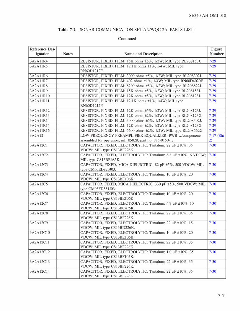
Table 7-2 SONAR COMMUNICATION SET AN/WQC-2A, PARTS LIST -
Continued
Reference Des-ignation Notes Name and Description
FigureNumber
3A2A11R4 RESISTOR, FIXED, FILM: 15K ohms ±5%, 1/2W; MIL type RL20S153J. 7-293A2A11R5 RESISTOR, FIXED, FILM: 12.1K ohms ±1%, 1/4W; MIL type
RN60D1212F.7-29
3A2A11R6 RESISTOR, FIXED, FILM: 3000 ohms ±5%, 1/2W; MIL type RL20S302J. 7-293A2A11R7 RESISTOR, FIXED, FILM: 402 ohms ±1%, 1/4W; MIL type RN60D4020F. 7-293A2A11R8 RESISTOR, FIXED, FILM: 8200 ohms ±5%, 1/2W; MIL type RL20S822J. 7-293A2A11R9 RESISTOR, FIXED, FILM: 15K ohms ±5%, 1/2W; MIL type RL20S153J. 7-293A2A11R10 RESISTOR, FIXED, FILM: 12K ohms ±5%, 1/2W; MIL type RL20S123J. 7-293A2A11R11 RESISTOR, FIXED, FILM: 12.1K ohms ±1%, 1/4W; MIL type
RN60D1212F.7-29
3A2A11R12 RESISTOR, FIXED, FILM: 12K ohms ±5%, 1/2W; MIL type RL20S123J. 7-293A2A11R13 RESISTOR, FIXED, FILM: 12K ohms ±2%, 1/2W; MIL type RL20S123G. 7-293A2A11R14 RESISTOR, FIXED, FILM: 3000 ohms ±5%, 1/2W; MIL type RL20S302J. 7-293A2A11R15 RESISTOR, FIXED, FILM: 12K ohms ±2%, 1/2W; MIL type RL20S123G. 7-293A2A11R16 RESISTOR, FIXED, FILM: 5600 ohms ±2%, 1/2W; MIL type RL20S562G. 7-293A2A12 LOW FREQUENCY PREAMPLIFIER EQUALIZER: PWB w/components
assembled for operation; mfr 05828, part no. 885-0150-1.7-17 (Sht2)
3A2A12C1 CAPACITOR, FIXED, ELECTROLYTIC: Tantalum; 22 uF ±10%, 35VDCW; MIL type CS13BF226K.
7-30
3A2A12C2 CAPACITOR, FIXED, ELECTROLYTIC: Tantalum; 6.8 uF ±10%, 6 VDCW;MIL type CS13BB685K.
7-30
3A2A12C3 CAPACITOR, FIXED, MICA DIELECTRIC: 82 pF ±5%, 500 VDCW; MILtype CM05ED820J03.
7-30
3A2A12C4 CAPACITOR, FIXED, ELECTROLYTIC: Tantalum; 10 uF ±10%, 20VDCW; MIL type CS13BE106K.
7-30
3A2A12C5 CAPACITOR, FIXED, MICA DIELECTRIC: 330 pF ±5%, 500 VDCW; MILtype CM05FD331J03.
7-30
3A2A12C6 CAPACITOR, FIXED, ELECTROLYTIC: Tantalum; 10 uF ±10%, 20VDCW; MIL type CS13BE106K.
7-30
3A2A12C7 CAPACITOR, FIXED, ELECTROLYTIC: Tantalum; 4.7 uF ±10%, 10VDCW; MIL type CS13BC475K.
7-30
3A2A12C8 CAPACITOR, FIXED, ELECTROLYTIC: Tantalum; 22 uF ±10%, 35VDCW; MIL type CS13BF226K.
7-30
3A2A12C9 CAPACITOR, FIXED, ELECTROLYTIC: Tantalum; 22 uF ±10%, 15VDCW; MIL type CS13BD226K.
7 30
3A2A12C10 CAPACITOR, FIXED, ELECTROLYTIC: Tantalum; 10 uF ±10%, 20VDCW; MIL type CS13BE106K.
7-30
3A2A12C11 CAPACITOR, FIXED, ELECTROLYTIC: Tantalum; 22 uF ±10%, 35VDCW; MIL type CS13BF226K.
7-30
3A2A12C12 CAPACITOR, FIXED, ELECTROLYTIC: Tantalum; 1.0 uF ±10%, 35VDCW; MIL type CS13BF105K.
7-30
3A2A12C13 CAPACITOR, FIXED, ELECTROLYTIC: Tantalum; 22 uF ±10%, 35VDCW; MIL type CS13BF226K.
7-30
3A2A12C14 CAPACITOR, FIXED, ELECTROLYTIC: Tantalum; 22 uF ±10%, 35VDCW; MIL type CS13BF226K.
7-30
SE340-AH-OMI-010
7-51

Table 7-2 SONAR COMMUNICATION SET AN/WQC-2A, PARTS LIST -
Continued
Reference Des-ignation Notes Name and Description
FigureNumber
3A2A12C15 CAPACITOR, FIXED, ELECTROLYTIC: Tantalum; 10 uF ±10%, 20VDCW; MIL type CS13BE106K.
7-30
3A2A12C16 CAPACITOR, FIXED, ELECTROLYTIC: Tantalum; 22 uF ±10%, 35VDCW; MIL type CS13BF226K.
7-30
3A2A12C17 CAPACITOR, FIXED, ELECTROLYTIC: Tantalum; 1.0 uF ±10%, 35VDCW; MIL type CS13BF105K.
7-30
3A2A12C18 CAPACITOR, FIXED, ELECTROLYTIC: Tantalum; 22 uF ±10%, 35VDCW; MIL type CS13BF226K.
7-30
3A2A12C19 CAPACITOR, FIXED, ELECTROLYTIC: Tantalum; 4.7 uF ±10%, 35VDCW; MIL type CS13BF475K.
7-30
3A2A12C20 CAPACITOR, FIXED, ELECTROLYTIC: Tantalum; 4.7 uF ±10%, 35VDCW; MIL type CS13BF475K.
7-30
3A2A12CR1 SEMICONDUCTOR DEVICE, DIODE: MIL type 1N3611. 7-303A2A12CR2 SEMICONDUCTOR DEVICE, DIODE: MIL type 1N3611. 7-303A2A12J1 JACK, TIP: Accom 0.080 in. dia test probe; yellow teflon body; mfr 98291,
part no. 026-4003-234, 05828, dwg 2163-0010-005.7-30
3A2A12J2 JACK, TIP: Accom 0.080 in. dia test probe; green teflon body; mfr 98291,part no. 026-4003-235, 05828, dwg 2163-0010-006.
7-30
3A2A12J3 JACK, TIP: Accom 0.080 in. dia test probe; black teflon body; mfr 98291,part no. 026-4003-230, 05828, dwg 2163-0010-001.
7-30
3A2A12J4 JACK TIP: Accom 0.080 in. dia test probe; green teflon body; mfr 98291,part no. 026-4003-235, 05828, dwg 2163-0010-006.
7-30
3A2A12MP1through3A2A12MP5
PAD, COMPONENT: Plastic; 0.305 in. OD by 0.125 in. thk; mfr 07047, partno. 10033DAP, 05828, dwg 1000-1013-0001.
7-30
3A2A12MP6through3A2A12MP12
PAD, COMPONENT: Plastic; 0.350 in. OD by 0.021 in. thk; mfr 07047, partno. 10007DAP, 05828, dwg 1000-1013-0007.
7-30
3A2A12Q1 TRANSISTOR: MIL type 2N1711. 7-303A2A12Q2 TRANSISTOR: MIL type 2N1132. 7-303A2A12Q3through3A2A12Q8
TRANSISTOR: MIL type 2N1711. 7-30
3A2A12Q9through3A2A12Q12
TRANSISTOR: MIL type 2N2222A. 7-30
3A2A12R1 RESISTOR, FIXED, FILM: 15K ohms ±5%, 1/4W; MIL type RL07S153J. 7-303A2A12R2 RESISTOR, FIXED, COMPOSITION: 39 ohms ±5%, 1/4W; MIL type
RC07GF390J.7-30
3A2A12R3 RESISTOR, FIXED, FILM: 180K ohms ±5%, 1/4W; MIL type RL07S184J. 7-303A2A12R4 RESISTOR, FIXED, FILM: 27K ohms ±5%, 1/4W; MIL type RL07S273J. 7-303A2A12R5 RESISTOR, FIXED, FILM: 56K ohms ±5%, 1/4W; MIL type RL07S563J. 7-303A2A12R6 RESISTOR, FIXED, FILM: 22K ohms ±5%, 1/4W; MIL type RL07S223J. 7-303A2A12R7 RESISTOR, FIXED, FILM: 4300 ohms ±5%, 1/4W; MIL type RL07S432J. 7-303A2A12R8 RESISTOR, FIXED, FILM: 2700 ohms ±5%, 1/4W; MIL type RL07S272J. 7-30
SE340-AH-OMI-010
7-52

Table 7-2 SONAR COMMUNICATION SET AN/WQC-2A, PARTS LIST -
Continued
Reference Des-ignation Notes Name and Description
FigureNumber
3A2A12R9 RESISTOR, FIXED, COMPOSITION: 24 ohms ±5%, 1/4W; MIL typeRC07GF240J.
7-30
3A2A12R10 RESISTOR, FIXED, FILM: 150K ohms ±5%, 1/4W; MIL type RL07S154J. 7-303A2A12R11 RESISTOR, FIXED, COMPOSITION: 62K ohms ±5%, 1/4W; MIL type
RC07GF623J.7-30
3A2A12R12 RESISTOR, FIXED, FILM: 82K ohms ±5%, 1/4W; MIL type RL07S823J. 7-303A2A12R13 RESISTOR, FIXED, FILM: 82K ohms ±5%, 1/4W; MIL type RL07S823J. 7-303A2A12R14 RESISTOR, FIXED, FILM: 2200 ohms ±5%, 1/4W; MIL type RL07S222J. 7-303A2A12R15 RESISTOR, FIXED, FILM: 4700 ohms ±5%, 1/4W; MIL type RL07S472J. 7-303A2A12R16 RESISTOR, FIXED, FILM: 5100 ohms ±5%, 1/4W; MIL type RL07S512J. 7-303A2A12R17 RESISTOR, FIXED, FILM: 270 ohms ±5%, 1/2W; MIL type RL20S271J. 7-303A2A12R18 RESISTOR, FIXED, FILM: 47.5 K ohms ±1%, 1/10W; MIL type
RN55C4752F.7-30
3A2A12R19 RESISTOR, FIXED, FILM: 46.4K ohms ±1%, 1/10W; MIL typeRN55C4642F.
7-30
3A2A12R20 RESISTOR, FIXED, FILM: 43.2K ohms ±1%, 1/10W; MIL typeRN55C4322F.
7-30
3A2A12R21 RESISTOR, FIXED, FILM: 15K ohms ±1%, 1/10W; MIL type RN55C1502F. 7-303A2A12R22 RESISTOR, FIXED, FILM: 82K ohms ±5%, 1/4W; MIL type RL07S823J. 7-303A2A12R23 RESISTOR, FIXED, FILM: 82K ohms ±5%, 1/4W; MIL type RL07S823J. 7-303A2A12R24 RESISTOR, FIXED, FILM: 2200 ohms ±5%, 1/4W; MIL type RL07S222J. 7-303A2A12R25 RESISTOR, FIXED, FILM: 4700 ohms ±5%, 1/4W; MIL type RL07S472J. 7-303A2A12R26 RESISTOR, FIXED, FILM: 270 ohms ±5%, 1/2W; MIL type RL20S271J. 7-303A2A12R27 RESISTOR, FIXED, FILM: 5100 ohms ±5%, 1/4W; MIL type RL07S512J. 7-303A2A12R28 RESISTOR, FIXED, FILM: 47.5K ohms ±1%, 1/10W; MIL type
RN55C4752F.7-30
3A2A12R29 RESISTOR, FIXED, FILM: 46.4K ohms ±1%, 1/10W; MIL typeRN55C4642F.
7-30
3A2A12R30 RESISTOR, FIXED, FILM: 2000 ohms ±5%, 1/2W; MIL type RL20S202J. 7-303A2A12R31 RESISTOR, FIXED, FILM: 8060 ohms ±1%, 1/10W; MIL type
RN55C8061F.7-30
3A2A12R32 RESISTOR, FIXED, COMPOSITION: 1000 ohms ±5%, 1/4W; MIL typeRC07GF102J.
7-30
3A2A12R33 RESISTOR, FIXED, COMPOSITION: 1000 ohms ±5%, 1/4W; MIL typeRC07GF102J.
7-30
3A2A12R34 RESISTOR, FIXED, COMPOSITION: 620 ohms ±5%, 1/4W; MIL typeRC07GF621J.
7-30
3A2A12R35 RESISTOR, FIXED, COMPOSITION: 620 ohms ±5%, 1/4W; MIL typeRC07GF621J.
7-30
3A2A12R36 RESISTOR, FIXED, COMPOSITION: 270 ohms ±5%, 1/4W; MIL typeRC07GF271J.
7-30
3A2A12R37 RESISTOR, FIXED, COMPOSITION: 270 ohms ±5%, 1/4W; MIL typeRC07GF271J.
7-30
3A2A12R38 RESISTOR, FIXED, FILM: 3900 ohms ±5%, 1/4W; MIL type RL07S392J. 7-303A2A12R39 RESISTOR, FIXED, FILM: 3900 ohms ±5%, 1/4W; MIL type RL07S392J. 7-30
SE340-AH-OMI-010
7-53

Table 7-2 SONAR COMMUNICATION SET AN/WQC-2A, PARTS LIST -
Continued
Reference Des-ignation Notes Name and Description
FigureNumber
3A2A12T1 TRANSFORMER, AUDIO FREQUENCY: pri 600 ohms impd, CT, 72 ohmsDCR; sec 600 ohms impd, CT, 92 ohms DCR; type TF5SX17ZZ configura-tion; mfr 05828, part no. 5608-0005-001.
7-30
3A2A13 BALANCED DEMODULATOR HIGH: PWB w/components assembled foroperation; mfr 05828, part no. 885-0050-1.
7-17 (Sht2)
3A2A13C1 CAPACITOR, FIXED, ELECTROLYTIC: Tantalum; 1.0 uF ±10%, 35VDCW; MIL type CS13BF105K.
7-31
3A2A13C2 CAPACITOR, FIXED, ELECTROLYTIC: Tantalum; 1.0 uF ±10%, 35VDCW; MIL type CS13BF105K.
7-31
3A2A13C3 CAPACITOR, FIXED, ELECTROLYTIC: Tantalum; 22 uF ±10%, 35VDCW; MIL type CS13BF226K.
7-31
3A2A13C4 CAPACITOR, FIXED, ELECTROLYTIC: Tantalum; 22 uF ±10%, 35VDCW; MIL type CS13BF226K.
7-31
3A2A13C5 CAPACITOR, FIXED, ELECTROLYTIC: Tantalum; 1.0 uF ±10%, 50VDCW; MIL type CS13BG105K.
7-31
3A2A13C6 CAPACITOR, FIXED, CERAMIC DIELECTRIC: 0.1 uF ±10%, 100 VDCW;MIL type CK06BX104K.
7-31
3A2A13C7 CAPACITOR, FIXED, ELECTROLYTIC: Tantalum; 4.7 uF ±10%, 50VDCW; MIL type CS13BG475K.
7-31
3A2A13C8 CAPACITOR, FIXED, CERAMIC DIELECTRIC: 0.1 uF ±10%, 100 VDCW;MIL type CK06BX104K.
7-31
3A2A13C9 CAPACITOR, FIXED, CERAMIC DIELECTRIC: 0.1 uF ±10%, 100 VDCW;MIL type CK06BX104K.
7-31
3A2A13C10 CAPACITOR, FIXED, CERAMIC DIELECTRIC: 0.47 uF ±10%, 50 VDCW;MIL type CK06BX474K.
7-31
3A2A13C11 CAPACITOR, FIXED, ELECTROLYTIC: Tantalum; 15 uF ±10%, 20VDCW; MIL type CS13BE156K.
7-31
3A2A13C12 CAPACITOR, FIXED, ELECTROLYTIC: Tantalum; 33 uF ±10%, 10VDCW; MIL type CS13BC336K.
7-31
3A2A13C13 CAPACITOR, FIXED, ELECTROLYTIC: Tantalum; 1.0 uF ±10%, 35VDCW; MIL type CS13BF105K.
7-31
3A2A13CR1 SEMICONDUCTOR DEVICE, DIODE: MIL type 1N4307. 7-313A2A13CR2 SEMICONDUCTOR DEVICE, DIODE: MIL type 1N964B. 7-313A2A13CR3 SEMICONDUCTOR DEVICE, DIODE: MIL type 1N751A. 7-313A2A13CR4 SEMICONDUCTOR DEVICE, DIODE: MIL type 1N914. 7-313A2A13CR5 SEMICONDUCTOR DEVICE, DIODE: MIL type 1N914. 7-313A2A13J1 JACK, TIP: Accom 0.080 in. dia test probe; yellow teflon body; mfr 98291,
part no. 026-4003-234, 05828, dwg 2163-0010-005.7-31
3A2A13J2 JACK, TIP: Accom 0.080 in. dia test probe; yellow teflon body; mfr 98291,part no. 026-4003-234, 05828, dwg 2163-0010-005.
7-31
3A2A13J3 JACK, TIP: Accom 0.080 in. dia test probe; green teflon body; mfr 98291,part no. 026-4003-235, 05828, dwg 2163-0010-006.
7-31
3A2A13J4 JACK, TIP: Accom 0.080 in. dia test probe; green teflon body; mfr 98291,part no. 026-4003-235, 05828, dwg 2163-0010-006.
7-31
3A2A13J5 JACK, TIP: Accom 0.080 in. dia test probe; black teflon body; mfr 98291,part no. 026-4003-230, 05828, dwg 2163-0010-001.
7-31
SE340-AH-OMI-010
7-54
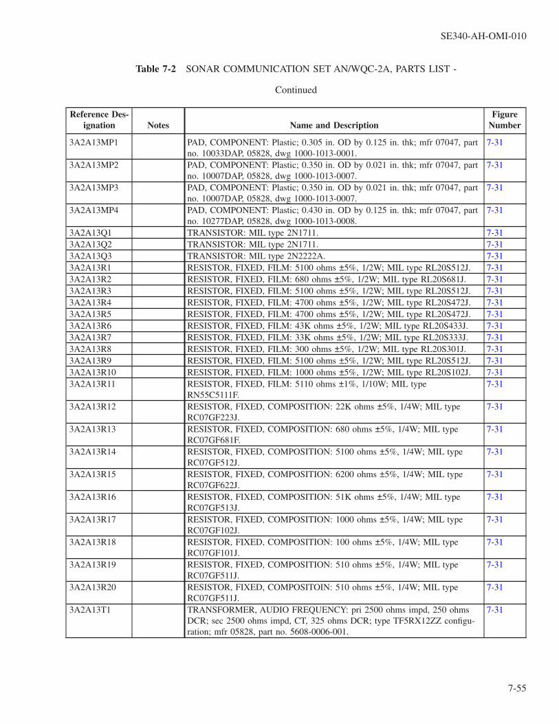
Table 7-2 SONAR COMMUNICATION SET AN/WQC-2A, PARTS LIST -
Continued
Reference Des-ignation Notes Name and Description
FigureNumber
3A2A13MP1 PAD, COMPONENT: Plastic; 0.305 in. OD by 0.125 in. thk; mfr 07047, partno. 10033DAP, 05828, dwg 1000-1013-0001.
7-31
3A2A13MP2 PAD, COMPONENT: Plastic; 0.350 in. OD by 0.021 in. thk; mfr 07047, partno. 10007DAP, 05828, dwg 1000-1013-0007.
7-31
3A2A13MP3 PAD, COMPONENT: Plastic; 0.350 in. OD by 0.021 in. thk; mfr 07047, partno. 10007DAP, 05828, dwg 1000-1013-0007.
7-31
3A2A13MP4 PAD, COMPONENT: Plastic; 0.430 in. OD by 0.125 in. thk; mfr 07047, partno. 10277DAP, 05828, dwg 1000-1013-0008.
7-31
3A2A13Q1 TRANSISTOR: MIL type 2N1711. 7-313A2A13Q2 TRANSISTOR: MIL type 2N1711. 7-313A2A13Q3 TRANSISTOR: MIL type 2N2222A. 7-313A2A13R1 RESISTOR, FIXED, FILM: 5100 ohms ±5%, 1/2W; MIL type RL20S512J. 7-313A2A13R2 RESISTOR, FIXED, FILM: 680 ohms ±5%, 1/2W; MIL type RL20S681J. 7-313A2A13R3 RESISTOR, FIXED, FILM: 5100 ohms ±5%, 1/2W; MIL type RL20S512J. 7-313A2A13R4 RESISTOR, FIXED, FILM: 4700 ohms ±5%, 1/2W; MIL type RL20S472J. 7-313A2A13R5 RESISTOR, FIXED, FILM: 4700 ohms ±5%, 1/2W; MIL type RL20S472J. 7-313A2A13R6 RESISTOR, FIXED, FILM: 43K ohms ±5%, 1/2W; MIL type RL20S433J. 7-313A2A13R7 RESISTOR, FIXED, FILM: 33K ohms ±5%, 1/2W; MIL type RL20S333J. 7-313A2A13R8 RESISTOR, FIXED, FILM: 300 ohms ±5%, 1/2W; MIL type RL20S301J. 7-313A2A13R9 RESISTOR, FIXED, FILM: 5100 ohms ±5%, 1/2W; MIL type RL20S512J. 7-313A2A13R10 RESISTOR, FIXED, FILM: 1000 ohms ±5%, 1/2W; MIL type RL20S102J. 7-313A2A13R11 RESISTOR, FIXED, FILM: 5110 ohms ±1%, 1/10W; MIL type
RN55C5111F.7-31
3A2A13R12 RESISTOR, FIXED, COMPOSITION: 22K ohms ±5%, 1/4W; MIL typeRC07GF223J.
7-31
3A2A13R13 RESISTOR, FIXED, COMPOSITION: 680 ohms ±5%, 1/4W; MIL typeRC07GF681F.
7-31
3A2A13R14 RESISTOR, FIXED, COMPOSITION: 5100 ohms ±5%, 1/4W; MIL typeRC07GF512J.
7-31
3A2A13R15 RESISTOR, FIXED, COMPOSITION: 6200 ohms ±5%, 1/4W; MIL typeRC07GF622J.
7-31
3A2A13R16 RESISTOR, FIXED, COMPOSITION: 51K ohms ±5%, 1/4W; MIL typeRC07GF513J.
7-31
3A2A13R17 RESISTOR, FIXED, COMPOSITION: 1000 ohms ±5%, 1/4W; MIL typeRC07GF102J.
7-31
3A2A13R18 RESISTOR, FIXED, COMPOSITION: 100 ohms ±5%, 1/4W; MIL typeRC07GF101J.
7-31
3A2A13R19 RESISTOR, FIXED, COMPOSITION: 510 ohms ±5%, 1/4W; MIL typeRC07GF511J.
7-31
3A2A13R20 RESISTOR, FIXED, COMPOSITOIN: 510 ohms ±5%, 1/4W; MIL typeRC07GF511J.
7-31
3A2A13T1 TRANSFORMER, AUDIO FREQUENCY: pri 2500 ohms impd, 250 ohmsDCR; sec 2500 ohms impd, CT, 325 ohms DCR; type TF5RX12ZZ configu-ration; mfr 05828, part no. 5608-0006-001.
7-31
SE340-AH-OMI-010
7-55

Table 7-2 SONAR COMMUNICATION SET AN/WQC-2A, PARTS LIST -
Continued
Reference Des-ignation Notes Name and Description
FigureNumber
3A2A13T2 TRANSFORMER, AUDIO FREQUENCY: pri 2500 ohms impd, 250 ohmsDCR; sec 2500 ohms impd, CT, 325 ohms DCR; type TF5RX12ZZ configu-ration; mfr 05828, part no. 5608-0006-001.
7-31
3A2A13U1 MICROCIRCUIT, LINEAR: Voltage comparator; mfr 05828, part no. 4827-0120-001.
7-31
3A2A13Y1 CRYSTAL UNIT, QUARTZ: 8.0875 kHz; type CR-88A/U holder; mfr 05828,part no. 2309-0017-002.(Attaching Parts) H(1), AP(1), CE(2), DN(1)
7-31
3A2A14 HIGH FREQUENCY RECEIVER AMPLIFIER: PWB w/componentsassembled for operation; mfr 05828, part no. 885-0365-1.
7-17 (Sht2)
3A2A14C1 CAPACITOR, FIXED, ELECTROLYTIC: Tantalum; 10 uF ±10%, 20VDCW; MIL type CS13BE106K.
7-32
3A2A14C2 CAPACITOR, FIXED, ELECTROLYTIC: Tantalum; 10 uF ±10%, 50VDCW; MIL type CS13BG106K.
7-32
3A2A14C3 CAPACITOR, FIXED, ELECTROLYTIC: Tantalum; 10 uF ±10%, 20VDCW; MIL type CS13BE106K.
7-32
3A2A14C4 CAPACITOR, FIXED, MICA DIELECTRIC: 620 pF ±5%, 500 VDCW; MILtype CM20BD621JN3.
7-32
3A2A14C5through3A2A14C8
CAPACITOR, FIXED, ELECTROLYTIC: Tantalum; 10 uF ±10%, 20VDCW; MIL type CS13BE106K.
7-32
3A2A14J1 JACK, TIP: Accom 0.080 in. dia test probe; green teflon body; mfr 98291,part no. 026-4003-235, 05828, dwg 2163-0010-006.
7-32
3A2A14J2 JACK, TIP: Accom 0.080 in. dia test probe; yellow teflon body; mfr 98291,part no. 026-4003-234, 05828, dwg 2163-0010-005.
7-32
3A2A14J3 JACK, TIP: Accom 0.080 in. dia test probe; red teflon body; mfr 98291, partno. 026-4003-232, 05828, dwg 2163-0010-003.
7-32
3A2A14J4 JACK, TIP: Accom 0.080 in. dia test probe; black teflon body; mfr 98291,part no. 026-4003-230, 05828, dwg 2163-0010-001.
7-32
3A2A14MP1through3A2A14MP5
PAD, COMPONENT: Plastic; 0.350 in. OD by 0.021 in. thk; mfr 07047, partno. 10007DAP, 05828, dwg 1000-1013-0007.
7-32
3A2A14Q1 TRANSISTOR: MIL type 2N1711. 7-323A2A14Q2 TRANSISTOR: MIL type 2N1132. 7-323A2A14Q3 TRANSISTOR: MIL type 2N1711. 7-323A2A14Q4 TRANSISTOR: MIL type 2N1132. 7-323A2A14Q5 TRANSISTOR: MIL type 2N1711. 7-323A2A14R1 RESISTOR, FIXED, FILM: 180K ohms ±5%, 1/2W; MIL type RL20S184J. 7-323A2A14R2 RESISTOR, FIXED, FILM: 27K ohms ±5%, 1/2W; MIL type RL20S273J. 7-323A2A14R3 RESISTOR, FIXED, FILM: 56K ohms ±5%, 1/2W; MIL type RL20S563J. 7-323A2A14R4 RESISTOR, FIXED, FILM: 15K ohms ±5%, 1/2W; MIL type RL20S153J. 7-323A2A14R5 RESISTOR, FIXED, FILM: 12.1K ohms ±1%, 1/4W; MIL type
RN60D1212F.7-32
3A2A14R6 RESISTOR, FIXED, FILM: 3000 ohms ±5%, 1/2W; MIL type RL20S302J. 7-323A2A14R7 RESISTOR, FIXED, FILM: 121 ohms ±1%, 1/4W; MIL type RN60D1210F. 7-32
SE340-AH-OMI-010
7-56

Table 7-2 SONAR COMMUNICATION SET AN/WQC-2A, PARTS LIST -
Continued
Reference Des-ignation Notes Name and Description
FigureNumber
3A2A14R8 RESISTOR, FIXED, FILM: 8200 ohms ±5%, 1/2W; MIL type RL20S822J. 7-323A2A14R9 RESISTOR, FIXED, FILM: 15K ohms ±5%, 1/2W; MIL type RL20S153J. 7-323A2A14R10 RESISTOR, FIXED, FILM: 12K ohms ±5%, 1/2W; MIL type RL20S123J. 7-323A2A14R11 RESISTOR, FIXED, FILM: 12.1K ohms ±1%, 1/4W; MIL type
RN60D1212F.7-32
3A2A14R12 RESISTOR, FIXED, FILM: 12K ohms ±5%, 1/2W; MIL type RL20S123J. 7-323A2A14R13 RESISTOR, FIXED, FILM: 2200 ohms ±2%, 1/2W; MIL type RL20S222G. 7-323A2A14R14 RESISTOR, FIXED, FILM: 3000 ohms ±5%, 1/2W; MIL type RL20S302J. 7-323A2A14R15 RESISTOR, FIXED, FLIM: 590 ohms ±1%, 1/8W; MIL type RN60C5900F. 7-323A2A15 HIGH FREQUENCY PREAMPLIFIER EQUALIZER: PWB w/components
assembled for operation; mfr 05828, part no. 885-0340-1.7-17 (Sht2)
3A2A15C1 CAPACITOR, FIXED, ELECTROLYTIC: Tantalum; 0.39 uF ±10%, 35VDCW; MIL type CS13BF394K.
7-33
3A2A15C2 CAPACITOR, FIXED, ELECTROLYTIC: Tantalum; 4.7 uF ±10%, 10VDCW; MIL type CS13BC475K.
7-33
3A2A15C3 CAPACITOR, FIXED, MICA DIELECTRIC: 820 pF ±5%, 500 VDCW; MILtype CM06FD821J03.
7-33
3A2A15C4 CAPACITOR, FIXED, ELECTROLYTIC: Tantalum; 1.5 uF ±10%, 20VDCW; MIL type CS13BE155K.
7-33
3A2A15C5 CAPACITOR, FIXED, ELECTROLYTIC: Tantalum; 4.7 uF ±10%, 10VDCW; MIL type CS13BC475K.
7-33
3A2A15C6 CAPACITOR, FIXED, ELECTROLYTIC: Tantalum; 10 uF ±10%, 50VDCW; MIL type CS13BG106K.
7-33
3A2A15C7 CAPACITOR, FIXED, ELECTROLYTIC: Tantalum; 10 uF ±10%, 50VDCW; MIL type CS13BG106K.
7-33
3A2A15C8 CAPACITOR, FIXED, MICA DIELECTRIC: 2400 pF ±5%, 500 VDCW;MIL type CM06FD242J03.
7-33
3A2A15C9 CAPACITOR, FIXED, ELECTROLYTIC: Tantalum; 1.0 uF ±10%, 50VDCW; MIL type CS13BG105K.
7-33
3A2A15C10 CAPACITOR, FIXED, ELECTROLYTIC: Tantalum; 1.0 uF ±10%, 50VDCW; MIL type CS13BG105K.
7-33
3A2A15C11 CAPACITOR, FIXED, MICA DIELECTRIC: 4700 pF ±5%, 500 VDCW;MIL type CM06FD472J03.
7-33
3A2A15C12 CAPACITOR, FIXED, ELECTROLYTIC: Tantalum; 1.0 uF ±10%, 50VDCW; MIL type CS13BG105K.
7-33
3A2A15C13 CAPACITOR, FIXED, ELECTROLYTIC: Tantalum; 1.0 uF ±10%, 50VDCW; MIL type CS13BG105K.
7-33
3A2A15C14 CAPACITOR, FIXED, ELECTROLYTIC: Tantalum; 4.7 uF ±10%, 50VDCW; MIL type CS13BG475K.
7-33
3A2A15C15 CAPACITOR, FIXED, ELECTROLYTIC: Tantalum; 1.0 uF ±10%, 50VDCW; MIL type CS13BG105K.
7-33
3A2A15CR1 SEMICONDUCTOR DEVICE, DIODE: MIL type 1N3611. 7-333A2A15CR2 SEMICONDUCTOR DEVICE, DIODE: MIL type 1N3611. 7-333A2A15J1 JACK, TIP: Accom 0.080 in. dia test probe; red teflon body; mfr 98291, part
no. 026-4003-232, 05828, dwg 2163-0010-003.7-33
SE340-AH-OMI-010
7-57

Table 7-2 SONAR COMMUNICATION SET AN/WQC-2A, PARTS LIST -
Continued
Reference Des-ignation Notes Name and Description
FigureNumber
3A2A15J2 JACK, TIP: Accom 0.080 in. dia test probe; yellow teflon body; mfr 98291,part no. 026-4003-234, 05828, dwg 2163-0010-005.
7-33
3A2A15J3 JACK, TIP: Accom 0.080 in. dia test probe; green teflon body; mfr 98291,part no. 026-4003-235, 05828, dwg 2163-0010-006.
7-33
3A2A15J4 JACK, TIP: Accom 0.080 in. dia test probe; black teflon body; mfr 98291,part no. 026-4003-230, 05828, dwg 2163-0010-001.
7-33
3A2A15L1 REACTOR: Audio inductor; 0.08 H ±3% at 4 mA, 23 ohms ±10% DCR;type TF5RX20ZZ configuration; mfr 05828, part no. 1800-0002-001.(Attaching Parts) L(1), BB(1), CG(2), DO(1)
7-33
3A2A15L2 REACTOR: Audio inductor; 0.08 H ±3% at 4 mA, 23 ohms ±10% DCR;type TF5RX20ZZ configuration; mfr 05828, part no. 1800-0002-001.(Attaching Parts) L(1), BB(1), CG(2), DO(1)
7-33
3A2A15MP1 PAD, COMPONENT: Plastic; 0.305 in. OD by 0.125 in. thk; mfr 07047, partno. 10033DAP, 05828, dwg 1000-1013-0001.
7-33
3A2A15MP2 PAD, COMPONENT: Plastic; 0.305 in. OD by 0.125 in. thk; mfr 07047, partno. 10033DAP, 05828, dwg 1000-1013-0001.
7-33
3A2A15MP3through3A2A15MP5
PAD, COMPONENT: Plastic; 0.350 in. OD by 0.021 in. thk; mfr 07047, partno. 10007DAP, 05828, dwg 1000-1013-0007.
7-33
3A2A15Q1through3A2A15Q3
TRANSISTOR: MIL type 2N1711. 7-33
3A2A15Q4 TRANSISTOR: MIL type 2N2222A. 7-333A2A15Q5 TRANSISTOR: MIL type 2N2222A. 7-333A2A15R1 RESISTOR, FIXED, FILM: 15K ohms ±5%, 1/2W; MIL type RL20S153J. 7-333A2A15R2 RESISTOR, FIXED, FILM: 1600 ohms ±5%, 1/2W; MIL type RL20S162J. 7-333A2A15R3 RESISTOR, FIXED, FILM: 68K ohms ±5%, 1/2W; MIL type RL20S683J. 7-333A2A15R4 RESISTOR, FIXED, FILM: 10K ohms ±5%, 1/2W; MIL type RL20S103J. 7-333A2A15R5 RESISTOR, FIXED, FILM: 249 ohms ±1%, 1/10W; MIL type RN55C2490F. 7-333A2A15R6 RESISTOR, FIXED, FILM: 1150 ohms ±1%, 1/4W; MIL type RN60D1151F. 7-333A2A15R7 RESISTOR, FIXED, FILM: 20K ohms ±5%, 1/2W; MIL type RL20S203J. 7-333A2A15R8 RESISTOR, FIXED, FILM: 510 ohms ±5%, 1/2W; MIL type RL20S511J. 7-333A2A15R9 RESISTOR, FIXED, FILM: 7500 ohms ±5%, 1/2W; MIL type RL20S752J. 7-333A2A15R10 RESISTOR, FIXED, FILM: 200 ohms ±5%, 1/2W; MIL type RL20S201J. 7-333A2A15R11 RESISTOR, FIXED, FILM: 2000 ohms ±5%, 1/2W; MIL type RL20S202J. 7-333A2A15R12 RESISTOR, FIXED, FILM: 360 ohms ±5%, 1W; MIL type RL32S361J. 7-333A2A15R13 RESISTOR, FIXED, FILM: 300 ohms ±5%, 1W; MIL type RL32S301J. 7-333A2A15R14 RESISTOR, FIXED, FILM: 100K ohms ±5%, 1/2W; MIL type RL20S104J. 7-333A2A15R15 RESISTOR, FIXED, FILM: 100K ohms ±5%, 1/2W; MIL type RL20S104J. 7-333A2A15R16 RESISTOR, FIXED, FILM: 620 ohms ±5%, 1/2W; MIL type RL20S621J. 7-333A2A15R17 RESISTOR, FIXED, FILM: 8200 ohms ±5%, 1/2W; MIL type RL20S822J. 7-333A2A15R18 RESISTOR, FIXED, COMPOSITION: 680 ohms ±5%, 1/4W; MIL type
RC07GF681J.7-33
3A2A15R19 RESISTOR, FIXED, FILM: 510 ohms ±5%, 1/2W; MIL type RL20S511J. 7-333A2A15R20 RESISTOR, FIXED, FILM: 100K ohms ±5%, 1/2W; MIL type RL20S104J. 7-33
SE340-AH-OMI-010
7-58

Table 7-2 SONAR COMMUNICATION SET AN/WQC-2A, PARTS LIST -
Continued
Reference Des-ignation Notes Name and Description
FigureNumber
3A2A15R21 RESISTOR, FIXED, FILM: 100K ohms ±5%, 1/2W; MIL type RL20S104J. 7-333A2A15R22 RESISTOR, FIXED, FILM: 2400 ohms ±5%, 1/2W; MIL type RL20S242J. 7-333A2A15R23 Not used.3A2A15R24 RESISTOR, FIXED, FILM: 620 ohms ±5%, 1/2W; MIL type RL20S621J. 7-333A2A15R25 RESISTOR, FIXED, COMPOSITION: 270 ohms ±5%, 1/4W; MIL type
RC07GF271J.7-33
3A2A15T1 TRANSFORMER, AUDIO FREQUENCY: pri 50 ohms impd, CT, 3.6 ohmsDCR; sec 2000 ohms impd, 155 ohms DCR; type TF4RX21YY configuration;mfr 05828, part no. 5608-0003-001
7-33
3A2A16 SUMMING CIRCUIT: PWB w/components assembled for operation; mfr05828, part no. 885-0130-1.
7-17 (Sht2)
3A2A16C1 CAPACITOR, FIXED, PLASTIC DIELECTRIC: 4700 pF ±5%, 50 VDCW;MIL type CFR04RSA472JM.
7-34
3A2A16C2 CAPACITOR, FIXED, PLASTIC DIELECTRIC: 4700 pF ±5%, 50 VDCW;MIL type CFR04RSA472JM.
7-34
3A2A16C3 CAPACITOR, FIXED, ELECTROLYTIC: Tantalum; 10 uF ±10%, 35VDCW; MIL type CS13BF106K.
7-34
3A2A16C4 CAPACITOR, FIXED, PLASTIC DIELECTRIC: 0.027 uF ±5%, 50 VDCW;MIL type CFR04RSA273JM.
7-34
3A2A16C5 CAPACITOR, FIXED, PLASTIC DIELECTRIC: 1800 pF ±5%, 50 VDCW;MIL type CFR04RSA182JM.
7-34
3A2A16C6 CAPACITOR, FIXED, ELECTROLYTIC: Tantalum; 4.7 uF ±10%, 35VDCW; MIL type CS13BF475K.
7-34
3A2A16C7 CAPACITOR, FIXED, ELECTROLYTIC: Tantalum; 1.5 uF ±10%, 35VDCW; MIL type CS13BF155K.
7-34
3A2A16C8 CAPACITOR, FIXED, ELECTROLYTIC: Tantalum; 10 uF ±10%, 35VDCW; MIL type CS13BF106K.
7-34
3A2A16C9 CAPACITOR, FIXED, PLASTIC DIELECTRIC: 0.039 uF ±5%, 50 VDCW;MIL type CFR04RSA393JM.
7-34
3A2A16C10 CAPACITOR, FIXED, PLASTIC DIELECTRIC: 1200 pF ±5%, 50 VDCW;MIL type CFR04RSA122JM.
7-34
3A2A16C11 CAPACITOR, FIXED, PLASTIC DIELECTRIC: 0.015 uF ±5%, 50 VDCW;MIL type CFR04RSA153JM.
7-34
3A2A16C12 CAPACITOR, FIXED, PLASTIC DIELECTRIC: 0.015 uF ±5%, 50 VDCW;MIL type CFR04RSA153JM.
7-34
3A2A16C13 CAPACITOR, FIXED, PLASTIC DIELECTRIC: 2700 pF ±5%, 50 VDCW;MIL type CFR04RSA272JM.
7-34
3A2A16C14 CAPACITOR, FIXED, PLASTIC DIELECTRIC: 2700 pF ±5%, 50 VDCW;MIL type CFR04RSA272JM.
7-34
3A2A16C15 CAPACITOR, FIXED, PLASTIC DIELECTRIC: 1200 pF ±5%, 50 VDCW;MIL type CFR04RSA122JM.
7-34
3A2A16C16 CAPACITOR, FIXED, PLASTIC DIELECTRIC: 0.015 uF ±5%, 50 VDCW;MIL type CFR04RSA153JM.
7-34
3A2A16C17 CAPACITOR, FIXED, PLASTIC DIELECTRIC: 0.015 uF ±5%, 50 VDCW;MIL type CFR04RSA153JM.
7-34
SE340-AH-OMI-010
7-59

Table 7-2 SONAR COMMUNICATION SET AN/WQC-2A, PARTS LIST -
Continued
Reference Des-ignation Notes Name and Description
FigureNumber
3A2A16C18 CAPACITOR, FIXED, CERAMIC DIELECTRIC: 1000 pF ±10%, 200VDCW; MIL type CK05BX102K.
7-34
3A2A16C19 CAPACITOR, FIXED, MICA DIELECTRIC: 680 pF ±5%, 500 VDCW; MILtype CM06FD681J03.
7-34
3A2A16CR1 SEMICONDUCTOR DEVICE, DIODE: MIL type 1N3611. 7-343A2A16J1 JACK, TIP: Accom 0.080 in. dia test probe; green teflon body; mfr 98291,
part no. 026-4003-235, 05828, dwg 2163-0010-006.7-34
3A2A16J2 JACK, TIP: Accom 0.080 in. dia test probe; green teflon body; mfr 98291,part no. 026-4003-235, 05828, dwg 2163-0010-006.
7-34
3A2A16J3 JACK, TIP: Accom 0.080 in. dia test probe; yellow teflon body; mfr 98291,part no. 026-4003-234, 05828, dwg 2163-0010-005.
7-34
3A2A16J4 JACK, TIP: Accom 0.080 in. dia test probe; black teflon body; mfr 98291,part no. 026-4003-230, 05828, dwg 2163-0010-001.
7-34
3A2A16J5 JACK, TIP: Accom 0.080 in. dia test probe; yellow teflon body; mfr 98291,part no. 026-4003-234, 05828, dwg 2163-0010-005.
7-34
3A2A16K1 RELAY, ARMATURE: DPDT; MIL type M5757/9-004. 7-343A2A16MP1through3A2A16MP6
PAD, COMPONENT: Plastic; 0.305 in. OD by 0.125 in. thk; mfr 07047, partno. 10033DAP, 05828, dwg 1000-1013-0001.
7-34
3A2A16Q1through3A2A16Q6
TRANSISTOR: MIL type 2N2222A. 7-34
3A2A16R1 RESISTOR, FIXED, FILM: 35.7 ohms ±1%, 1/8W; MIL type RN55D35R7F. 7-343A2A16R2 RESISTOR, FIXED, FILM: 14.7 ohms ±1%, 1/8W; MIL type RN55D14R7F. 7-343A2A16R3 RESISTOR, FIXED, FILM: 634 ohms ±1%, 1/10W; MIL type RN55C6340F. 7-343A2A16R4 RESISTOR, FIXED, FILM: 25.5K ohms ±1%, 1/10W; MIL type
RN55C2552F.7-34
3A2A16R5 RESISTOR, FIXED, FILM: 22.1K ohms ±1%, 1/10W; MIL typeRN55C2212F.
7-34
3A2A16R6 RESISTOR, FIXED, COMPOSITION: 2200 ohms ±5%, 1/4W; MIL typeRC07GF222J.
7-34
3A2A16R7 RESISTOR, FIXED, FILM: 2000 ohms ±1%, 1/10W; MIL typeRN55C2001F.
7-34
3A2A16R8 RESISTOR, FIXED, FILM: 1870 ohms ±1%, 1/10W; MIL typeRN55C1871F.
7-34
3A2A16R9 RESISTOR, FIXED, COMPOSITION: 2200 ohms ±5%, 1/4W; MIL typeRC07GF222J.
7-34
3A2A16R10 RESISTOR, FIXED, COMPOSITION: 330 ohms ±5%, 1/4W; MIL typeRC07GF331J.
7-34
3A2A16R11 RESISTOR, FIXED, COMPOSITION: 5100 ohms ±5%, 1/4W; MIL typeRC07GF512J.
7-34
3A2A16R12 RESISTOR, FIXED, FILM: 7500 ohms ±1%, 1/10W; MIL typeRN55C7501F.
7-34
3A2A16R13 RESISTOR, FIXED, FILM: 7500 ohms ±1%, 1/10W; MIL typeRN55C7501F.
7-34
SE340-AH-OMI-010
7-60

Table 7-2 SONAR COMMUNICATION SET AN/WQC-2A, PARTS LIST -
Continued
Reference Des-ignation Notes Name and Description
FigureNumber
3A2A16R14 RESISTOR, FIXED, COMPOSITION: 1000 ohms ±5%, 1/4W; MIL typeRC07GF102J.
7-34
3A2A16R15 RESISTOR, FIXED, FILM: 5110 ohms ±1%, 1/10W; MIL typeRN55C5111F.
7-34
3A2A16R16 RESISTOR, FIXED, FILM: 5230 ohms ±1%, 1/10W; MIL typeRN55C5231F.
7-34
3A2A16R17 RESISTOR, FIXED, COMPOSITION: 2200 ohms ±5%, 1/4W; MIL typeRC07GF222J.
7-34
3A2A16R18 RESISTOR, FIXED, FILM: 931 ohms ±1%, 1/10W; MIL type RN55C9310F. 7-343A2A16R19 RESISTOR, FIXED, FILM: 37.4K ohms ±1%, 1/8W; MIL type
RN55D3742F.7-34
3A2A16R20 RESISTOR, FIXED, FILM: 24.9K ohms ±1%, 1/10W; MIL typeRN55C2492F.
7-34
3A2A16R21 RESISTOR, FIXED, COMPOSITION: 22 ohms ±5%, 1/4W; MIL typeRC07GF220J.
7-34
3A2A16R22 RESISTOR, FIXED, COMPOSITION: 5100 ohms ±5%, 1/4W; MIL typeRC07GF512J.
7-34
3A2A16T1 TRANSFORMER, AUDIO FREQUENCY: pri 10K/2.5K ohms (split) impd;sec 200/50 ohms (split) impd; type TF4RX13YY configuration; mfr 05828,part no. 5608-0012-001.(Attaching Parts) L(2), CG(2), DO(2)
7-34
3A2A16T2 TRANSFORMER, AUDIO FREQUENCY: pri 4000 ohms impd, CT, 180ohms DCR; sec 10,000 ohms impd, CT, 440 ohms DCR; type TF5SX13ZZconfiguration; mfr 05828, part no. 5608-0019-001.
7-34
3A3 FINAL AMPLIFIER ASSEMBLY: Drawer chassis w/components assembledfor operation; mfr 05828, part no. 885-0240-2.
7-7
3A3B1 FAN, TUBEAXIAL: 115 volts, 0.21 amps, single phase, 50-60 Hz input;3300 RPM, CW rotation, 275 CFM; mfr 05828, part no. 2603-0014-003.(Attaching Parts) A(4), BE(8), CK(8), DQ(8), clamp 3A3MP30 through3A3MP37
7-36 (Sht1)
3A3C1 CAPACITOR, FIXED, ELECTROLYTIC: Tantalum; 56 µF ±10%, 6 VDCW;MIL type CS13BB566K.
7-36 (Sht2)
3A3C2 CAPACITOR, FIXED, ELECTROLYTIC: Tantalum; 56 µF ±10%, 6 VDCW;MIL type CS13BB566K.
7-36 (Sht2)
3A3C3 CAPACITOR, FIXED, ELECTROLYTIC: Tantalum; 270 µF ±10%, 6VDCW; MIL type CS13BB277K.
7-36 (Sht2)
3A3C4 CAPACITOR, FIXED, ELECTROLYTIC: Tantalum; 270 µF ±10%, 6VDCW; MIL type CS13BB277K.
7-36 (Sht2)
3A3C5 CAPACITOR, FIXED, ELECTROLYTIC: Tantalum; 22 µF ±10%, 35VDCW; MIL type CS13BF226K.
7-36 (Sht2)
3A3C6 CAPACITOR, FIXED, ELECTROLYTIC: Tantalum; 22 µF ±10%, 35VDCW; MIL type CS13BF226K.
7-36 (Sht2)
3A3C7 CAPACITOR, FIXED: 0.47 µF, 400 VDCW; MIL type CH53B1NE474K. 7-36 (Sht1)
3A3CR1 Not used.
SE340-AH-OMI-010
7-61

Table 7-2 SONAR COMMUNICATION SET AN/WQC-2A, PARTS LIST -
Continued
Reference Des-ignation Notes Name and Description
FigureNumber
3A3CR2 SEMICONDUCTOR DEVICE, DIODE: MIL type 1N3611. 7-36 (Sht1)
3A3CR3 SEMICONDUCTOR DEVICE, DIODE: MIL type 1N3611. 7-36 (Sht1)
3A3CR4through3A3CR8
Not used.
3A3CR9 SEMICONDUCTOR DEVICE, DIODE: MIL type, JAN 1N3891. 7-36 (Sht1)
3A3CR10,3A3CR11
Not used.
3A3CR12 SEMICONDUCTOR DEVICE, DIODE: MIL type, JAN 1N3891. 7-36 (Sht1)
3A3E1 through3A3E24
TERMINAL, STUD: MIL type SE17XC03. 7-36 (Sht2)
3A3E25 TERMINAL, LUG: MIL type MS77068-1.(Attaching Parts) Z(1), AS(1), CG(1)
7-36 (Sht2)
3A3E26 TERMINAL, LUG: MIL type MS77068-1.(Attaching Parts) Z(1), AS(1), CG(1)
7-36 (Sht2)
3A3E27through3A3E50
TERMINAL, STUD: MIL type SE17XC03. 7-36 (Sht2)
3A3E51 TERMINAL, LUG: MIL type MS77068-1.(Attaching Parts) Z(1), AS(1), CG(1)
7-36 (Sht2)
3A3E52 TERMINAL, LUG: MIL type MS77068-1.(Attaching Parts) Z(1), AS(1), CG(1)
7-36 (Sht2)
3A3E53through3A3E60
TERMINAL, STUD: MIL type SE17XC03. 7-36 (Sht2)
3A3E61 Not used.3A3E62 Not used.3A3E63through3A3E70
TERMINAL, STUD: MIL type SE17XC03. 7-36 (Sht2)
3A3E71through3A3E75
TERMINAL, STUD: mfr 58712, part no. 1390-C. 7-36 (Sht2)
3A3E76 Not used.3A3E77 TERMINAL, STUD: mfr 58712, part no. 1390-C. 7-36 (Sht
3)3A3E78through3A3E84
TERMINAL, STUD: MIL type SE17XC03.
3A3E85 TERMINAL, LUG: MIL type MS77068-1.(Attaching Parts) L(1), AT(1), CG(1), DO(1)
7-36 (Sht1)
SE340-AH-OMI-010
7-62

Table 7-2 SONAR COMMUNICATION SET AN/WQC-2A, PARTS LIST -
Continued
Reference Des-ignation Notes Name and Description
FigureNumber
3A3E86 TERMINAL, LUG: MIL type MS77068-2.(Attaching Parts) BF(1), CK(1)
7-36 (Sht1)
3A3E87through3A3E89
Not used.
3A3E90through3A3E92
TERMINAL, STUD: MIL type SE17XC03. 7-36 (Sht2)
3A3E93through3A3E98
TERMINAL, STUD: mfr 58712, part no. 1390C. 7-36 (Sht3)
3A3E99,3A3E100
TERMINAL, STUD: MIL type SE206D01(Attaching Parts) AR(4), J(4), DA(4)
7-36 (Sht1)
3A3E101through3A3E148
TERMINAL, STUD: mfr 58712, part no. 1390-B. 7-36 (Sht4)
3A3F1 through3A3F12
FUSE, CARTRIDGE: 130 volts, 5 amps; mfr 05828, part no. 5103-0004-002. 7-35
3A3F13 Not used.3A3F14through3A3F25
FUSE, CARTRIDGE: 130 volts, 5 amps; mfr 05828, part no. 5103-0004-002. 7-35
3A3F spare FUSE, CARTRIDGE: 130 volts, 5 amps; mfr 05828, part no. 5103-0004-002. 7-353A3F spare FUSE, CARTRIDGE: 130 volts, 5 amps; mfr 05828, part no. 5103-0004-002. 7-353A3J1 CONNECTOR, RECEPTACLE, ELECTRICAL: 34 male contacts; MIL type
M28748/3F00F1A.(Attaching Parts) L(4), AH(4), CG(4), DO(4)
7-36 (Sht1)
3A3J2 CONNECTOR, RECEPTACLE, ELECTRICAL: 66 female contacts; MILtype M28748/4J00F1A.(Attaching Parts) L(4), AH(4), CG(4), DO(4)
7-36 (Sht1)
3A3J3 CONNECTOR, RECEPTACLE, ELECTRICAL: 20 female contacts; MILtype M28748/8-D00F1A.(Attaching Parts) L(4), AH(4), CG(4), DO(4)
7-36 (Sht1)
3A3L1 REACTOR: Audio inductor; 0.1 H ±2% at 4 mA, 11 ohms ±20% DCR; typeTF5RX20ZZ configuration; mfr 05828, part no. 1800-0006-001.(Attaching Parts) BS(1), CM(1), DS(1)
7-36 (Sht2)
3A3MP1,3A3MP2
HANDLE, BOW: Brass, black chemical coating; MIL type MS39087-4.(Attaching Parts) B(2), BT(2), CR(2), DU(2)
7-35
3A3MP3 BRACKET ASSEMBLY, RESISTOR: MIL type MS75009-33.(Attaching Parts) BT(2), CR(2)
7-36 (Sht1)
3A3MP4through3A3MP13
SCREW, CAPTIVE: No. 10-32 UNF-3A thd by 0.975 in. lg OA; mfr 05828,part no. 1000-1390-002.
7-35
3A3MP14,3A3MP15
SCREW, CAPTIVE: No. 10-32 UNF-3A thd by 1.207 in. lg OA; mfr 05828,part no. 1000-1390-005.
7-35
SE340-AH-OMI-010
7-63

Table 7-2 SONAR COMMUNICATION SET AN/WQC-2A, PARTS LIST -
Continued
Reference Des-ignation Notes Name and Description
FigureNumber
3A3MP16,3A3MP17
PIN, ECCENTRIC: Steel, cad pl; 1.640 in. lg OA, 0.375 in. dia pin shaft;supplied w/bushings to accom 0.088-0.125 in. panel thk; mfr 05828, part no.1000-1576-001.(Attaching Parts) Q(1), CT(1), DV(1)
7-35
3A3MP18,3A3MP19
BUSHING, MACHINE THREAD: Steel, cad pl; 1/2-20 UNF-3A thd, 0.975in. lg OA by 0.625 in. dia; accom 0.062-0.437 in. panel thk; mfr 05828, partno. 1000-1408-001.(Attaching Parts) AD(1), DA(3)
7-36 (Sht1)
3A3MP20,3A3MP21
SLIDE, DRAWER, EXTENSION: Steel, cad pl; 13.1 in. lg by 3.25 in. h maxby 0. 274 in. w; supplied with 5/16-24 UNF-3A pivot screw; mfr 05828, partno. 1436-0002-001.(Attaching Parts) T(1), BT(6), CR(6), CW(1), DG(1)
7-36 (Sht1)
3A3MP22 FILTER, AIR: Aluminum; 10.50 in. lg by 8.00 in. w by 0.50 in. thk; mfr05828, part no. 2613-0001-001.(Attaching Parts) BO(3), CO(3), DS(3)
7-36 (Sht1)
3A3MP23 HEAT SINK, SPECIAL: Aluminum, steel, and plastic materials; 11.782 in. lgOA by 9.375 in. dia incl fins; mfr 05828, part no. 4818-0002-001.
7-36 (Sht1)
3A3MP24 GASKET: Rubber; 1.82 in. lg by 0.74 in. w by 0.12 in. thk; mfr 05828, partno. 885-0025-5.
7-36
3A3MP25 GASKET: Rubber; 9.14 in. lg by 0.50 in. w by 0.12 in. thk; mfr 05828, partno. 885-0028-5.
7-35
3A3MP26 GASKET: Rubber; 9.14 in. lg by 0.50 in. w by 0.12 in. thk; mfr 05828, partno. 885-0028-5.
7-35
3A3MP27 GASKET: Rubber; 12.10 in. lg by 0.50 in. w by 0.12 in. thk; mfr 05828, partno. 885-0028-6.
7-35
3A3MP28 Not used.3A3MP29 RETAINER, PCB: Aluminum alloy; 2.58 in. lg by 1.00 in. w by 0.12 in. thk;
used w/two steel positive locking studs (part no. 1000-1034-004); mfr 05828,part no. 885-0044-3.
7-36 (Sht1)
3A3MP30through3A3MP37
CLAMP, RIM CLINCHING: Steel w/nylon insert; 0.693 in. lg OA incl screwby 0.390 in. dia max; supplied w/pan hd screw (MS35233-15); mfr 05828,part no. 1000-1024-0002.
7-36 (Sht1)
3A3MP38 COVER, FUSE: Clear plastic; 15-1/4 in. lg by 2 in. w by 3/16 in. thk; mfr05828, part no. 885-0253.(Attaching Parts) BO(5), CO(5), DS(5)
7-35
3A3MP39through3A3MP43
POST, ELECTRICAL-MECHANICAL EQUIPMENT: CRES, painted gray;no. 8-32 UNC-2B thd size, 1-15/16 in. lg by 5/16 in. dia; mfr 05828, part no.885-0252.(Attaching Parts) AL(1 ea)
7-35
3A3MP443A3MP45
BRACKET ASSEMBLY, DIODE: mfr 12255, part no. FLSD-70450906.(Attaching Parts) AZ(4), DO(4), CF(4)
7-36 (Sht1)
3A3MP46through3A3MP54
SCREW, CAPTIVE: No. 8-32 UNC-3A thd by 0.810 in. lg OA; mfr 05828,part no. 1000-1423-003.
7-35
3A3MP55 PLATE, LEXAN INSULATOR: mfr 05828, part no. 885-0437. 7-36 (Sht1)
SE340-AH-OMI-010
7-64

Table 7-2 SONAR COMMUNICATION SET AN/WQC-2A, PARTS LIST -
Continued
Reference Des-ignation Notes Name and Description
FigureNumber
3A3P1 CONNECTOR, RECEPTACLE, ELECTRICAL: 66 male contacts; MIL typeM28748/3J40L1A.
7-36 (Sht1)
3A3P2 CONNECTOR, RECEPTACLE, ELECTRICAL: 20 male contacts; MIL typeM28748/7-D10L1A.
7-36 (Sht1)
3A3Q1 through3A3Q6
TRANSISTOR: NPN, silicon, high power; mfr 05828, part no. 4822-0022-001.
7-36 (Sht1)
3A3Q7 through3A3Q12
TRANSISTOR: NPN, silicon, high power; mfr 05828, part no. 4822-0022-001.
7-37
3A3Q13 TRANSISTOR: NPN, silicon, high power; mfr 05828, part no. 4822-0020-001.(Attaching Parts) BK(2), DQ(2)
7-36 (Sht1)
3A3Q14through3A3Q19
TRANSISTOR: PNP, silicon, high power; mfr 05828, part no. 4822-0023-002.
7-37
3A3Q20through3A3Q25
TRANSISTOR: PNP, silicon, high power; mfr 05828, part no. 4822-0023-002.
7-36 (Sht1)
3A3Q26 TRANSISTOR: PNP, silicon, high power; mfr 05828, part no. 4822-0021-001.(Attaching Parts) BK(2), DQ(2)
7-36 (Sht1)
3A3Q27 TRANSISTOR: NPN, silicon, high power; mfr 05828, part no. 4822-0020-001.(Attaching Parts) BK(2), DQ(2)
7-36 (Sht1)
3A3Q28through3A3Q29
TRANSISTOR: PNP, silicon, high power; mfr 05828, part no. 4822-0021-001.(Attaching Parts) BK(4), DQ(4)
7-36 (Sht1)
3A3R1 through3A3R48
RESISTOR, FIXED, WIRE WOUND: 0.47 ohms ±10%, 3W; MIL typeRW69VR47.
7-36 (Sht2)
3A3R49through3A3R50
RESISTOR, FIXED, FILM: 5600 ohms ±5%, 2W; MIL type RL42S562J. 7-36 (Sht2)
3A3R51through3A3R52
RESISTOR, FIXED, FILM: 180 ohms ±5%, 1/2 W; MIL type RL20S181J. 7-36 (Sht3)
3A3R53through3A3R54
RESISTOR, FIXED, WIRE WOUND: 4.75 ohms ±1%, 5W; mfr 91637, partno. G5C-4.75.
7-36 (Sht3)
3A3R55 RESISTOR, FIXED, WIRE WOUND: 100 ohms ±5%, 26W; MIL typeRW33V101.(Attaching Parts) Bracket assy 3A3MP3
7-36 (Sht1)
3A3R56through3A3R57
RESISTOR, FIXED, WIRE WOUND: 1100 ohms ±1%, 5W; MIL typeRW74U1101F.
7-36 (Sht2)
3A3R58through3A3R59
RESISTOR, FIXED, FILM: 30 ohms ±5%, 1W; MIL type RL32S300J. 7-36 (Sht3)
SE340-AH-OMI-010
7-65

Table 7-2 SONAR COMMUNICATION SET AN/WQC-2A, PARTS LIST -
Continued
Reference Des-ignation Notes Name and Description
FigureNumber
3A3R60 RESISTOR, FIXED, COMPOSITION: 82 ohms ±5%, 2W; MIL typeRC42GF820J.
7-36 (Sht2)
3A3R61through3A3R64
RESISTOR, FIXED, WIRE WOUND: Power; 0.06 ohms, 50W; MIL typeRE75GR060.
7-37
3A3R65 RESISTOR, FIXED, COMPOSITION: 390 ohms ±5%, 1/2W; MIL typeRCR20G391JS.
7-36 (Sht1)
3A3R66,3A3R67
RESISTOR, FIXCED, WIRE WOUND: 1.5 ohms ±5%, 3W; MIL typeRW69V1R5.
7-36 (Sht3)
3A3R68,3A3R69
RESISTOR, FIXED, WIRE WOUND: 7 ohms ±1%, 5W; mfr 91637, part no.G5C-7.
7-36 (Sht3)
3A3R70 RESISTOR, FIXED, WIRE WOUND: 7 ohms ±1%, 5W; mfr 91637, part no.G5C-7.
7-36 (Sht1)
3A3R71through3A3R94
RESISTOR, FIXED, COMPOSITION: 10 ohms ±5%, 1/2W; MIL type JANRCR20G100JS.
7-36 (Sht4)
3A3S1 SWITCH, THERMOSTATIC: Hermetically sealed; SPST, 5 amps; opens at197°F ±5%, closes at 177 °F ±5%; MIL type M24236/1-0820.
7-36 (Sht1)
3A3S2 SWITCH, THERMOSTATIC: Hermetically sealed; SPST, 5 amps; opens at170°F ±5%, closes at 150°F ±5%; MIL type M24236/1-0810.
7-36 (Sht1)
3A3T1 TRANSFORMER, AUDIO FREQUENCY: pri 65 ohms impd, 3 ohms DCR;sec 1630 ohms impd, 75 ohms DCR; Type TF5RX17ZZ configuration; mfr05828, part no. 5608-0021-001.(Attaching Parts) AT(4), CG(4)
7-37
3A3T2 TRANSFORMER, AUDIO FREQUENCY: pri 200 ohms impd, 10 ohmsDCR; sec 288 ohms impd, 15 ohms DCR; Type TF5RX12ZZ configuration;mfr 05828, part no. 5608-0022-001.(Attaching Parts) AT(4), CG(4)
7-37
3A3TB1 TERMINAL BOARD: 10 stud-type terminals; two single rows; MIL type16TB10.(Attaching Parts) O(2), AN(2), CR(2), DU(2)
7-36 (Sht1)
3A3XA1 CONNECTOR, RECEPTACLE, ELECTRICAL: Accom 30 pin contacts max,0.156 in. contact spacing; 3.240 in. lg OA by 0.670 in. h by 0.483 in. w; usedw/two polarizing keys (mfr 53711, part no. 5196055); mfr 05828, part no.2126-0027-001.(Attaching Parts) J(2), AZ(2), CF(4), DO(2)
7-37
3A3XA2 CONNECTOR, RECEPTACLE, ELECTRICAL: Accom 30 pin contacts max,0.156 in. contact spacing; 3.240 in. lg OA by 0.670 in. h by 0.483 in. w; usedw/two polarizing keys (mfr 53711, part no. 5196055); mfr 05828, part no.2126-0027-001.(Attaching Parts) J(2), AZ(2), CF(4), DO(2)
7-37
3A3XF1through3A3XF12
FUSEHOLDER, EXTRACTOR POST: MIL type FHL18G1-4.(Attaching Parts) AA(1 ea), DL(1 ea)
7-35
3A3XF13 Not used.
SE340-AH-OMI-010
7-66

Table 7-2 SONAR COMMUNICATION SET AN/WQC-2A, PARTS LIST -
Continued
Reference Des-ignation Notes Name and Description
FigureNumber
3A3XF14through3A3XF25
FUSEHOLDER, EXTRACTOR POST: MIL type FHL18G1-4.(Attaching Parts) AA(1 ea), DL(1 ea)
7-35
3A3XF spare FUSEHOLDER, EXTRACTOR POST: MIL type FHL18G1-4.(Attaching Parts) AA(1), DL(1)
7-35
3A3XF spare FUSEHOLDER, EXTRACTOR POST: MIL type FHL18G1-4.(Attaching Parts) AA(1), DL(1)
7-35
3A3XQ1through3A3XQ12
Not used.
3A3XQ13 SOCKET, ELECTRONIC COMPONENT: Two contacts, gold-pl berylliumcopper; molded plastic insulator body; 1.570 in. lg by 0.730 in. w max by0.350 in. h excl contacts; mfr 05828, part no. 2157-0006-001.(Attaching Parts) L(1), AJ(1), CG(1), DO(1)
7-36 (Sht1)
3A3XQ14through3A3XQ25
Not used.
3A3XQ26through3A3XQ27
SOCKET, ELECTRONIC COMPONENT: Two contacts, gold-pl berylliumcopper; molded plastic insulator body; 1.570 in. lg by 0.730 in. w max by0.350 in. h excl contacts; mfr 05828, part no. 2157-0006-001.(Attaching Parts) L(1), AJ(1), CG(1), DO(1)
7-36 (Sht1)
3A3XQ28through3A3XQ29
SOCKET, ELECTRONIC COMPONENT: Two contacts, gold-pl berylliumcopper; molded plastic insulator body; 1.570 in. lg by 0.730 in. w max by0.350 in. h excl contacts; mfr 05828, part no. 2157-0006-001.(Attaching Parts) L(1), AJ(1), CG(1), DO(1)
7-36 (Sht1)
3A3A1 LOW LEVEL FINAL AMPLIFIER: PWB w/components assembled foroperation; mfr 05828, part no. 885-0160-1.
7-36 (Sht1)
3A3A1C1,3A3A1C2
CAPACITOR, FIXED, ELECTROLYTIC: Tantalum; 22 µF ±10%, 35VDCW; MIL type CS13BF226K.
7-38
3A3A1C3 CAPACITOR, FIXED, ELECTROLYTIC: Tantalum; 22 µF ±10%, 50VDCW; MIL type CS13BG226K.
7-38
3A3A1C4 CAPACITOR, FIXED, ELECTROLYTIC: Tantalum; 10 µF ±10%, 35VDCW; MIL type CS13BF106K.
7-38
3A3A1C5 Not used.3A3A1C6through3A3A1C9
CAPACITOR, FIXED, ELECTROLYTIC: Tantalum; 10 µF ±10%, 35VDCW; MIL type CS13BF106K.
7-38
3A3A1C10 CAPACITOR, FIXED, CERAMIC DIELECTRIC: 22 pF ±10%, 200 VDCW;MIL type CK05BX220K.
7-38
3A3A1C11 CAPACITOR, FIXED, CERAMIC DIELECTRIC: 470 pf ±10%, 200 VDCW;MIL type CK05BX471K.
7-38
3A3A1C12 CAPACITOR, FIXED, ELECTROLYTIC: Tantalum; 10µF ±10%, 35 VDCW;MIL type CS13BF106K.
7-38
3A3A1C13 CAPACITOR, FIXED, CERAMIC DIELECTRIC: 22 pf ±10%, 200 VDCW;MIL type CK05BX220K.
7-38
SE340-AH-OMI-010
7-67

Table 7-2 SONAR COMMUNICATION SET AN/WQC-2A, PARTS LIST -
Continued
Reference Des-ignation Notes Name and Description
FigureNumber
3A3A1C14 CAPACITOR, FIXED, CERAMIC DIELECTRIC: 470 pF ±10%, 200VDCW; MIL type CK05BX471K.
7-38
3A3A1C15through3A3A1C16
CAPACITOR, FIXED, ELECTROLYTIC: Tantalum; 56 µF ±10%, 6 VDCW;MIL type CS13BB566K.
7-38
3A3A1CR1 SEMICONDUCTOR DEVICE, DIODE: MIL type 1N4148. 7-383A3A1CR2through3A3A1CR8
SEMICONDUCTOR DEVICE, DIODE: MIL type 1N3611. 7-38
3A3A1J1 JACK, TIP: Accom 0.080 in. dia test probe; yellow teflon body; mfr 98291,part no. 026-4003-234, 05828, dwg 2163-0010-005.
7-38
3A3A1J2 JACK, TIP: Accom 0.080 in. dia test probe; green teflon body; mfr 98291,part no. 026-4003-235, 05828, dwg 2163-0010-006.
7-38
3A3A1K1through3A3A1K3
RELAY, ARMATURE: DPDT; MIL type M5757/9-004. 7-38
3A3A1MP1 PAD, COMPONENT: Plastic, 0.305 in. OD by 0.125 in. thk; mfr 07047, partno. 10033DAP, 05828, dwg 1000-1013-0001.
7-38
3A3A1MP2 PAD, COMPONENT: Plastic, 0.305 in. OD by 0.125 in. thk; mfr 07047, partno. 10033DAP, 05828, dwg 1000-1013-0001.
7-38
3A3A1MP3through3A3A1MP5
PAD, COMPONENT: Plastic, 0.430 in. OD by 0.125 in. thk; mfr 07047, partno. 10277DAP, 05828, dwg 1000-1013-0008.
7-38
3A3A1MP6through3A3A1MP8
PAD, COMPONENT: Plastic, 0.800 in. lg by 0.400 in. w by 0.050 in. thk;mfr 07047, part no. 10105DAP, 05828, dwg 1000-1013-0017.
7-38
3A3A1Q1 TRANSISTOR: MIL type 2N1711. 7-383A3A1Q2 TRANSISTOR: MIL type 2N2905. 7-383A3A1R1 RESISTOR, FIXED, COMPOSITION: 5100 ohms ±5%, 1/4W; MIL type
RC07GF512J.7-38
3A3A1R2 RESISTOR, FIXED, COMPOSITION: 10K ohms ±5%, 1/4W; MIL typeRC07GF103J.
7-38
3A3A1R3 RESISTOR, FIXED, COMPOSITION: 10K ohms ±5%, 1/4W; MIL typeRC07GF103J.
7-38
3A3A1R4 RESISTOR, FIXED, COMPOSITION: 680 ohms ±5%, 1/4W; MIL typeRC07GF681J.
7-38
3A3A1R5 RESISTOR, VARIABLE, WIRE WOUND: 1000 ohms ±5%, 3/4W; MIL typeRT22C2P102.
7-38
3A3A1R6 RESISTOR, FIXED, COMPOSITION: 5100 ohms ±5%, 1/4W; MIL typeRC07GF512J.
7-38
3A3A1R7 RESISTOR, FIXED, COMPOSITION: 3600 ohms ±5%, 1/4W; MIL typeRC07GF362J.
7-38
3A3A1R8 RESETOR, FIXED, FILM: 3010 ohms ±1%, 1/4W; MIL type RN60D3011F. 7-383A3A1R9 RESBTOR, FIXED, FILM: 187 ohms ±1%, 1/4W; MIL type RN60D1870F. 7-383A3A1R10 RESISTOR, FIXED, FILM: 750 ohms ±1%, 1/4W; MIL type RN60D7500F. 7-38
SE340-AH-OMI-010
7-68
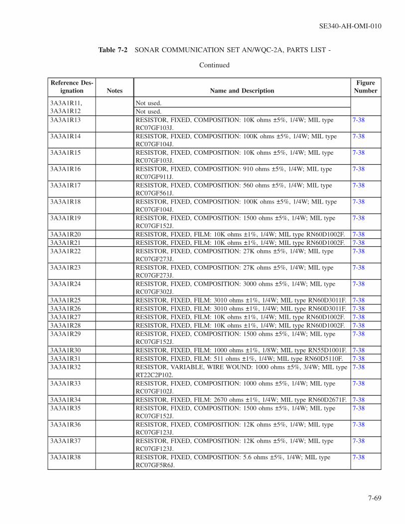
Table 7-2 SONAR COMMUNICATION SET AN/WQC-2A, PARTS LIST -
Continued
Reference Des-ignation Notes Name and Description
FigureNumber
3A3A1R11,3A3A1R12
Not used.Not used.
3A3A1R13 RESISTOR, FIXED, COMPOSITION: 10K ohms ±5%, 1/4W; MIL typeRC07GF103J.
7-38
3A3A1R14 RESISTOR, FIXED, COMPOSITION: 100K ohms ±5%, 1/4W; MIL typeRC07GF104J.
7-38
3A3A1R15 RESISTOR, FIXED, COMPOSITION: 10K ohms ±5%, 1/4W; MIL typeRC07GF103J.
7-38
3A3A1R16 RESISTOR, FIXED, COMPOSITION: 910 ohms ±5%, 1/4W; MIL typeRC07GF911J.
7-38
3A3A1R17 RESISTOR, FIXED, COMPOSITION: 560 ohms ±5%, 1/4W; MIL typeRC07GF561J.
7-38
3A3A1R18 RESISTOR, FIXED, COMPOSITION: 100K ohms ±5%, 1/4W; MIL typeRC07GF104J.
7-38
3A3A1R19 RESISTOR, FIXED, COMPOSITION: 1500 ohms ±5%, 1/4W; MIL typeRC07GF152J.
7-38
3A3A1R20 RESISTOR, FIXED, FILM: 10K ohms ±1%, 1/4W; MIL type RN60D1002F. 7-383A3A1R21 RESISTOR, FIXED, FILM: 10K ohms ±1%, 1/4W; MIL type RN60D1002F. 7-383A3A1R22 RESISTOR, FIXED, COMPOSITION: 27K ohms ±5%, 1/4W; MIL type
RC07GF273J.7-38
3A3A1R23 RESISTOR, FIXED, COMPOSITION: 27K ohms ±5%, 1/4W; MIL typeRC07GF273J.
7-38
3A3A1R24 RESISTOR, FIXED, COMPOSITION: 3000 ohms ±5%, 1/4W; MIL typeRC07GF302J.
7-38
3A3A1R25 RESISTOR, FIXED, FILM: 3010 ohms ±1%, 1/4W; MIL type RN60D3011F. 7-383A3A1R26 RESISTOR, FIXED, FILM: 3010 ohms ±1%, 1/4W; MIL type RN60D3011F. 7-383A3A1R27 RESISTOR, FIXED, FILM: 10K ohms ±1%, 1/4W; MIL type RN60D1002F. 7-383A3A1R28 RESISTOR, FIXED, FILM: 10K ohms ±1%, 1/4W; MIL type RN60D1002F. 7-383A3A1R29 RESISTOR, FIXED, COMPOSITION: 1500 ohms ±5%, 1/4W; MIL type
RC07GF152J.7-38
3A3A1R30 RESISTOR, FIXED, FILM: 1000 ohms ±1%, 1/8W; MIL type RN55D1001F. 7-383A3A1R31 RESISTOR, FIXED, FILM: 511 ohms ±1%, 1/4W; MIL type RN60D5110F. 7-383A3A1R32 RESISTOR, VARIABLE, WIRE WOUND: 1000 ohms ±5%, 3/4W; MIL type
RT22C2P102.7-38
3A3A1R33 RESISTOR, FIXED, COMPOSITION: 1000 ohms ±5%, 1/4W; MIL typeRC07GF102J.
7-38
3A3A1R34 RESISTOR, FIXED, FILM: 2670 ohms ±1%, 1/4W; MIL type RN60D2671F. 7-383A3A1R35 RESISTOR, FIXED, COMPOSITION: 1500 ohms ±5%, 1/4W; MIL type
RC07GF152J.7-38
3A3A1R36 RESISTOR, FIXED, COMPOSITION: 12K ohms ±5%, 1/4W; MIL typeRC07GF123J.
7-38
3A3A1R37 RESISTOR, FIXED, COMPOSITION: 12K ohms ±5%, 1/4W; MIL typeRC07GF123J.
7-38
3A3A1R38 RESISTOR, FIXED, COMPOSITION: 5.6 ohms ±5%, 1/4W; MIL typeRC07GF5R6J.
7-38
SE340-AH-OMI-010
7-69

Table 7-2 SONAR COMMUNICATION SET AN/WQC-2A, PARTS LIST -
Continued
Reference Des-ignation Notes Name and Description
FigureNumber
3A3A1R39 RESISTOR, FIXED, COMPOSITION: 5.6 ohms ±5%, 1/4W; MIL typeRC07GF5R6J.
7-38
3A3A1U1 MICROCIRCUIT, LINEAR: Operational amplifier; mfr 05828, part no. 4827-0140-001.
7-38
3A3A1U2 MICROCIRCUIT, LINEAR: Voltage multiplier; mfr 05828, part no. 4827-0123-001.
7-38
3A3A1U3 MICROCIRCUIT, LINEAR: Operational amplifier; mfr 05828, part no. 4827-0058-05.
7-38
3A3A1U4 MICROCIRCUIT, LINEAR: Operational amplifier; mfr 05828, part no. 4827-0058-05.
7-38
3A3A2 FINAL AMPLIFIER PROTECTION CIRCUIT: PWB w/componentsassembled for operation; mfr 53711, part no. 5403164.
7-36
3A3A2C1 CAPACITOR, FIXED, CERAMIC DIELECTRIC: 1.0 µF ±20%, 50 VDCW;mfr 72982, part no. 8131-050-651-105M.
7-39
3A3A2C2 CAPACITOR, FIXED, CERAMIC DIELECTRIC: 1.0 µF ±20%, 50 VDCW;mfr 72982, part no. 8131-050-651-105M.
7-39
3A3A2C3 CAPACITOR, FIXED, CERAMIC DIELECTRIC: 0.1 µF ±10%, 100 VDCW;MIL type CK05BX104K.
7-39
3A3A2C4 CAPACITOR, FIXED, CERAMIC DIELECTRIC: 0.01 µF ±10%, 200VDCW; MIL type CK06BX103K.
7-39
3A3A2CR1 SEMICONDUCTOR DEVICE, DIODE: Silicon, voltage-regulator; 15V;MIL-S-19500/115, MIL type 1N3024B.
7-39
3A3A2CR2 SEMICONDUCTOR DEVICE, DIODE: Silicon, rectifier; MIL-S-19500/228,MIL type 1N3611.
7-39
3A3A2CR3 SEMICONDUCTOR DEVICE, DIODE: Silicon, rectifier; MIL-S-19500/228,MIL type 1N3611.
7-39
3A3A2CR4 SEMICONDUCTOR DEVICE, DIODE: Silicon, rectifier; MIL-S-19500/228,MIL type 1N3611.
7-39
3A3A2J1 JACK TIP: accom 0.080 in. dia test probe; red teflon body; mfr 98291, partno. 026-4003-232.
7-39
3A3A2J2 JACK TIP: accom 0.080 in. dia test probe; black teflon body; mfr 98291, partno. 026-4003-230.
7-39
3A3A2J3 JACK TIP: accom 0.080 in. dia test probe; yellow teflon body; mfr 98291,part no. 026-4003-234.
7-39
3A3A2J4 JACK TIP: accom 0.080 in. dia test probe; yellow teflon body; mfr 98291,part no. 026-4003-234.
7-39
3A3A2MP1,3A3A2MP2
PAD, COMPONENT: Nylon; 0.375 in. OD by 0.115 in. thk; MIL typeM38527-06N.
7-39
3A3A2MP3through3A3[2]MP7
PAD, COMPONENT: Nylon; 0.355 in. OD by 0.042 in. thk; MIL typeM38527-05N.
7-39
3A3A2Q1 SEMICONDUCTOR DEVICE, OPTICALLY COUPLED ISOLATOR, SOLIDSTATE: MIL-S-19500/486, MIL type 4N22.
7-39
3A3A2Q2 SEMICONDUCTOR DEVICE, OPTICALLY COUPLED ISOLATOR, SOLIDSTATE: MIL-S-19500/486, MIL type 4N22.
7-39
SE340-AH-OMI-010
7-70

Table 7-2 SONAR COMMUNICATION SET AN/WQC-2A, PARTS LIST -
Continued
Reference Des-ignation Notes Name and Description
FigureNumber
3A3A2Q3 SEMICONDUCTOR DEVICE, TRANSISTOR: NPN, silicon; MIL-S-19500/225, MIL type 2N1711.
7-39
3A3A2Q4 SEMICONDUCTOR DEVICE, TRANSISTOR: PNP, silicon; MIL type2N4407.
7-39
3A3A2Q5 SEMICONDUCTOR DEVICE, TRANSISTOR: PNP, silicon; low power;NHL-S-19500/485, MIL type 2N5415.
7-39
3A3A2Q6 SEMICONDUCTOR DEVICE, TRANSISTOR: PNP, silicon; low power;MIL-S-19500/485, MIL type 2N5415.
7-39
3A3A2Q7 SEMICONDUCTOR DEVICE, TRANSISTOR: NPN, silicon; MIL-S-19500/225, MIL type 2N1711.
7-39
3A3A2R1 RESISTOR, FIXED, COMPOSITION: 1K ohms ±5%, 1/2W; MIL typeRCR20G102JS.
7-39
3A3A2R2 RESISTOR, FIXED, COMPOSITION: 100 ohms ±5%, 1/4W; MIL typeRCR07G101JS.
7-39
3A3A2R3 RESISTOR, VARIABLE, WIRE WOUND: 500 ohms ±5%; MIL typeRT24C2W501.
7-39
3A3A2R4 RESISTOR, FIXED, COMPOSITION: 390 ohms ±5%, 1/4W; MIL typeRCR07G391JS.
7-39
3A3A2R5 RESISTOR, FIXED, COMPOSITION: 390 ohms ±5%, 1/4W; MIL typeRCR07G391JS.
7-39
3A3A2R6 RESISTOR, VARIABLE, WIRE WOUND: 500 ohms ±5%; MIL typeRT24C2W501.
7-39
3A3A2R7 RESISTOR, FIXED, COMPOSITION: 100K ohms ±5%, 1/4W; MIL typeRCR07G104JS.
7-39
3A3A2R8 RESISTOR, FIXED, COMPOSITION: 100K ohms ±5%, 1/4W; MIL typeRCR07G104JS.
7-39
3A3A2R9 RESISTOR, FIXED, COMPOSITION: 24K ohms ±5%, 1/4W; MIL typeRCR07G243JS.
7-39
3A3A2R10 RESISTOR, FIXED, COMPOSITION: 2.7K ohms ±5%, 1/2W; MIL typeRCR20G272JS.
7-39
3A3A2R11 RESISTOR, FIXED, COMPOSITION: 560 ohms ±5%, 1/2W; MIL typeRCR20G561JS.
7-39
3A3A2R12 RESISTOR, FIXED, COMPOSITION: 18K ohms ±5%, 1/4W; MIL typeRCR07G183JS.
7-39
3A3A2R13 RESISTOR, FIXED, COMPOSITION: 4.7K ohms ±5%, 1/2W; MIL typeRCR20G472JS.
7-39
3A3A2R14 RESISTOR, FIXED, COMPOSITION: 560 ohms ±5%, 1/2W; MIL typeRCR20G561JS.
7-39
3A3A2R15 RESISTOR, FIXED, COMPOSITION: 100 ohms ±5%, 1/4W; MIL typeRCR07G101JS.
7-39
3A3A2R16 RESISTOR, FIXED, COMPOSITION: 20K ohms ±5%, 1/4W; MIL typeRCR07G203JS.
7-39
3A3A2R17 RESISTOR, FIXED, COMPOSITION: 2K ohms ±5%, 1/2W; MIL typeRCR20G202JS.
7-39
3A3A2R18 RESISTOR, FIXED, COMPOSITION: 100 ohms ±5%, 1/4W; MIL typeRCR07G101JS.
7-39
SE340-AH-OMI-010
7-71

Table 7-2 SONAR COMMUNICATION SET AN/WQC-2A, PARTS LIST -
Continued
Reference Des-ignation Notes Name and Description
FigureNumber
3A3A2R19 RESISTOR, FIXED, COMPOSITION: 2K ohms ±5%, 1/2W; MIL typeRCR20G202JS.
7-39
3A3A2S1 SWITCH, TOGGLE: SPDT NONE-ON-ON right angle mounting, horizontal;28 VDC, 5 amp; mfr 09353, part no. 7109A.
7-39
3A3A2U1 J-K FLIP-FLOP MICROCIRCUIT: digital, MIL type M38510/05102 (part no.MC14027B).
7-39
MATING CONNECTORS AND ACCESSORIESR-SB1P1 CONNECTOR, PLUG, ELECTRICAL: 26 no. 16 female contacts; 1.968 in.
dia, 1.531 in. lg; mfr 77820, part no. 10-214528-12H, 05828, dwg 2107-0004-014.
R-SB1P2 CONNECTOR, PLUG, ELECTRICAL: 26 no. 16 male contacts; 1.968 in.dia, 1.531 in. lg; mfr 77820, part no. 10-214528-121, 05828, dwg 2107-0004-015.
R-SB2P1 CONNECTOR, PLUG, ELECTRICAL: 26 no. 16 male contacts; 1.968 in.dia, 1.531 in. lg; mfr 77820, part no. 10-214528-12P, 05828, dwg 2107-0004-016.
R-SB2P2 CONNECTOR, PLUG, ELECTRICAL: 26 no. 16 female contacts; 1.968 in.dia, 1.531 in. lg; mfr 77820, part no. 10-214528-12S, 05828, dwg 2107-0004-017.
R-SB3P1 CONNECTOR, PLUG, ELECTRICAL: 37 no. 16 female contacts; 1.968 in.dia, 1.531 in. lg; mfr 77820, part no. 10-214528-21S, 05828, dwg 2107-0004-020.
R-SB3P2 CONNECTOR, PLUG, ELECTRICAL: 37 no. 16 male contacts; 1.968 in.dia, 1.531 in. lg; mfr 77820, part no. 10-214528-21P, 05828, dwg 2107-0004-019.
R-SB4P1 CONNECTOR, PLUG, ELECTRICAL: 2 no. 8 and 2 no. 16 female contacts;1.461 in. dia, 1.531 in. lg; mfr 77820, part no. 10-214520-24S, 05828, dwg2107-0004-012.
R-SB5P1 CONNECTOR, PLUG, ELECTRICAL: 15 no. 16 male contacts; 1.968 in.dia, 1.531 in. lg; mfr 77820, part no. 10-214528-17P, 05828, dwg no. 2107-0004-018.
R-SB6P1 CONNECTOR, PLUG, ELECTRICAL: 5 no. 16 male contacts; 1.123 in. dia,1.140 in. lg; mfr 77820, part no. 10-214514-5P, 05828, dwg 2107-0004-004.
R-SB7P1 CONNECTOR, PLUG, ELECTRICAL: 6 no. 16 male contacts; 1.123 in. dia,1.140 in. lg; mfr 77820, part no. 10-214514-6P, 05828, dwg 2107-0004-005.
R-SB8P1 CONNECTOR, PLUG, ELECTRICAL: 4 no. 16 male contacts; 1.123 in. dia,1.140 in. lg; mfr 77820, part no. 10-214514-2P, 05828, dwg 2107-0004-003.
R-SB9P1 CONNECTOR, PLUG, ELECTRICAL: 4 no. 16 male contacts; 1.123 in. dia,1.140 in. lg; mfr 77820, part no. 10-214514-2K, 05828, dwg 2107-0004-002.
R-SB10P1 CONNECTOR, PLUG, ELECTRICAL: 4 no. 16 male contacts; 1.123 in. dia,1.140 in. lg; mfr 77820, part no. 10-214514-21, 05828, dwg 2107-0004-001.
R-SB11P1 CONNECTOR, PLUG, ELECTRICAL: 26 no. 20 male contacts; MIL typeMS3116E16-26P.
R-SB12P1 CONNECTOR, PLUG, ELECTRICAL: 3 no. 16 male contacts; 1.123 in. dia,1.140 in. lg; mfr 77820, part no. 10-214514-7P, 05828, dwg 2107-0004-009.
SE340-AH-OMI-010
7-72

Table 7-2 SONAR COMMUNICATION SET AN/WQC-2A, PARTS LIST -
Continued
Reference Des-ignation Notes Name and Description
FigureNumber
R-SB13P1 CONNECTOR, PLUG, ELECTRICAL: 3 no. 16 male contacts; 1.123 in. dia,1.140 in. lg; mfr 77820, part no. 10-214514-7K, 05828, dwg 2107-0004-008.
R-SB14P1 CONNECTOR, PLUG, ELECTRICAL: 3 no. 16 male contacts; 1.123 in. dia,1.140 in. lg; mfr 77820, part no. 10-214514-7G, 05828, dwg 2107-0004-006.
R-SB15P1 CONNECTOR, PLUG, ELECTRICAL: 3 no. 16 male contacts; 1.123 in. dia,1.140 in. lg; mfr 77820, part no. 10-214514-71, 05828, dwg 2107-0004-007.
R-SB16P1 CONNECTOR, PLUG, ELECTRICAL: 8 no. 16 male contacts; 1.461 in. dia,1.531 in. lg; mfr 77820, part no. 10-214520-7P, 05828, dwg 2107-0004-011.
R-SB17P1 CONNECTOR, PLUG, ELECTRICAL: 8 no. 16 male contacts; 1.461 in. dia,1.531 in. lg; mfr 77820, part no. 10-214520-7G, 05828, dwg 2107-0004-010.
R-SB18P1 CONNECTOR, PLUG, ELECTRICAL: 14 no. 16 male contacts; 1.461 in.dia, 1.531 in. lg; mfr 77820, part no. 10-214520-27S, 05828, dwg 2107-0004-013.ADAPTER, CONNECTOR: Aluminum alloy, dull olive drab painted finish;0.7500-20 UNEF-2B thd, 1.375 in. lg, 0.938 in. max dia; mfr 05828, part no.2107-0005-001. (Five supplied.)ADAPTER, CONNECTOR: Aluminum alloy, dull olive drab painted finish;1.1875-18 UNEF-2B thd, 1.828 in. lg, 1.328 in. max dia; mfr 05828, part no.2107-0005-002. (Three supplied.)ADAPTER, CONNECTOR: Aluminum alloy, dull olive drab painted finish;1.4375-18 UNEF-2B thd, 2.750 in. lg, 1.828 in. max dia; mfr 05828, part no.2107-0005-003. (Two supplied.)CLAMP, CABLE, ELECTRICAL CONNECTOR: Aluminum alloy, dull olivedrab painted finish; 0.937F-20 UNEF-2B thd, 1.194 in. lg, 1.150 in. h max;mfr 05828, part no. 2107-0006-001.EXTENDER CARD, ELECTRONIC TEST: Accom 30 pin contacts max;4.50 in. lg incl fingers by 4.10 in. w: mfr 05828, part no. 885-0169-1. (Twosupplied.)EXTRACTOR, CIRCUIT CARD ASSEMBLY: U-shaped steel rod w/alumi-num tubing handle; 3.875 in. lg by 1.00 in. ea leg; mfr 05828, part no. 885-0049-1.
Table 7-3 LIST OF ATTACHING HARDWARE
LetterCode Name and Description
A CLAMP, FAN: CRES; 1.00 in. lg by 0.50 in. h by 0.415 in. d; mfr 05828, part no. 885-0221.B FERRULE, HANDLE: Brass, black oxide finish; 0.320 in. ID, 0.562 in. OD, 0.250 in. h; mfr 05828, part no.
1000-1414-001.C INSULATOR, BUSHING: Polytetrafluoroethylene; 0.265 in. ID, 0.359 in. OD, 0.110 in. thk; mfr 05828, part
no. 885-0146-2.D INSULATOR, BUSHING: Polytetrafluoroethylene; 0.265 in. ID, 0.359 in. OD, 0.171 in. thk; mfr 05828, part
no. 885-0146-1.E INSULATOR, WASHER: Mica; 0.204 in. ID, 0.625 in. OD, 0.003 in. thk; mfr 05828, part no. 1000-1410-
002.
SE340-AH-OMI-010
7-73
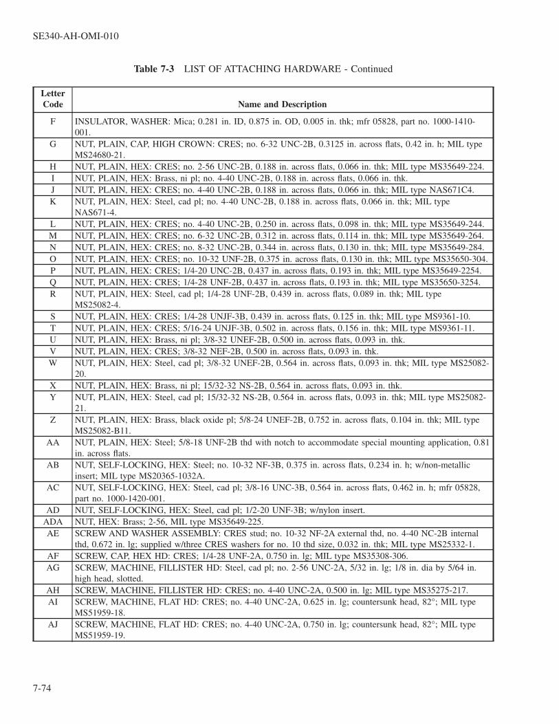
Table 7-3 LIST OF ATTACHING HARDWARE - Continued
LetterCode Name and Description
F INSULATOR, WASHER: Mica; 0.281 in. ID, 0.875 in. OD, 0.005 in. thk; mfr 05828, part no. 1000-1410-001.
G NUT, PLAIN, CAP, HIGH CROWN: CRES; no. 6-32 UNC-2B, 0.3125 in. across flats, 0.42 in. h; MIL typeMS24680-21.
H NUT, PLAIN, HEX: CRES; no. 2-56 UNC-2B, 0.188 in. across flats, 0.066 in. thk; MIL type MS35649-224.I NUT, PLAIN, HEX: Brass, ni pl; no. 4-40 UNC-2B, 0.188 in. across flats, 0.066 in. thk.J NUT, PLAIN, HEX: CRES; no. 4-40 UNC-2B, 0.188 in. across flats, 0.066 in. thk; MIL type NAS671C4.K NUT, PLAIN, HEX: Steel, cad pl; no. 4-40 UNC-2B, 0.188 in. across flats, 0.066 in. thk; MIL type
NAS671-4.L NUT, PLAIN, HEX: CRES; no. 4-40 UNC-2B, 0.250 in. across flats, 0.098 in. thk; MIL type MS35649-244.M NUT, PLAIN, HEX: CRES; no. 6-32 UNC-2B, 0.312 in. across flats, 0.114 in. thk; MIL type MS35649-264.N NUT, PLAIN, HEX: CRES; no. 8-32 UNC-2B, 0.344 in. across flats, 0.130 in. thk; MIL type MS35649-284.O NUT, PLAIN, HEX: CRES; no. 10-32 UNF-2B, 0.375 in. across flats, 0.130 in. thk; MIL type MS35650-304.P NUT, PLAIN, HEX: CRES; 1/4-20 UNC-2B, 0.437 in. across flats, 0.193 in. thk; MIL type MS35649-2254.Q NUT, PLAIN, HEX: CRES; 1/4-28 UNF-2B, 0.437 in. across flats, 0.193 in. thk; MIL type MS35650-3254.R NUT, PLAIN, HEX: Steel, cad pl; 1/4-28 UNF-2B, 0.439 in. across flats, 0.089 in. thk; MIL type
MS25082-4.S NUT, PLAIN, HEX: CRES; 1/4-28 UNJF-3B, 0.439 in. across flats, 0.125 in. thk; MIL type MS9361-10.T NUT, PLAIN, HEX: CRES; 5/16-24 UNJF-3B, 0.502 in. across flats, 0.156 in. thk; MIL type MS9361-11.U NUT, PLAIN, HEX: Brass, ni pl; 3/8-32 UNEF-2B, 0.500 in. across flats, 0.093 in. thk.V NUT, PLAIN, HEX: CRES; 3/8-32 NEF-2B, 0.500 in. across flats, 0.093 in. thk.W NUT, PLAIN, HEX: Steel, cad pl; 3/8-32 UNEF-2B, 0.564 in. across flats, 0.093 in. thk; MIL type MS25082-
20.X NUT, PLAIN, HEX: Brass, ni pl; 15/32-32 NS-2B, 0.564 in. across flats, 0.093 in. thk.Y NUT, PLAIN, HEX: Steel, cad pl; 15/32-32 NS-2B, 0.564 in. across flats, 0.093 in. thk; MIL type MS25082-
21.Z NUT, PLAIN, HEX: Brass, black oxide pl; 5/8-24 UNEF-2B, 0.752 in. across flats, 0.104 in. thk; MIL type
MS25082-B11.AA NUT, PLAIN, HEX: Steel; 5/8-18 UNF-2B thd with notch to accommodate special mounting application, 0.81
in. across flats.AB NUT, SELF-LOCKING, HEX: Steel; no. 10-32 NF-3B, 0.375 in. across flats, 0.234 in. h; w/non-metallic
insert; MIL type MS20365-1032A.AC NUT, SELF-LOCKING, HEX: Steel, cad pl; 3/8-16 UNC-3B, 0.564 in. across flats, 0.462 in. h; mfr 05828,
part no. 1000-1420-001.AD NUT, SELF-LOCKING, HEX: Steel, cad pl; 1/2-20 UNF-3B; w/nylon insert.
ADA NUT, HEX: Brass; 2-56, MIL type MS35649-225.AE SCREW AND WASHER ASSEMBLY: CRES stud; no. 10-32 NF-2A external thd, no. 4-40 NC-2B internal
thd, 0.672 in. lg; supplied w/three CRES washers for no. 10 thd size, 0.032 in. thk; MIL type MS25332-1.AF SCREW, CAP, HEX HD: CRES; 1/4-28 UNF-2A, 0.750 in. lg; MIL type MS35308-306.AG SCREW, MACHINE, FILLISTER HD: Steel, cad pl; no. 2-56 UNC-2A, 5/32 in. lg; 1/8 in. dia by 5/64 in.
high head, slotted.AH SCREW, MACHINE, FILLISTER HD: CRES; no. 4-40 UNC-2A, 0.500 in. lg; MIL type MS35275-217.AI SCREW, MACHINE, FLAT HD: CRES; no. 4-40 UNC-2A, 0.625 in. lg; countersunk head, 82°; MIL type
MS51959-18.AJ SCREW, MACHINE, FLAT HD: CRES; no. 4-40 UNC-2A, 0.750 in. lg; countersunk head, 82°; MIL type
MS51959-19.
SE340-AH-OMI-010
7-74

Table 7-3 LIST OF ATTACHING HARDWARE - Continued
LetterCode Name and Description
AK SCREW, MACHINE, FLAT HD: CRES; no. 6-32 UNC-2A, 0.375 in. lg; countersunk head, 82°; MIL typeMS51959-28.
AL SCREW, MACHINE, FLAT HD: CRES; no. 8-32 UNC-2A, 0.375 in. lg; countersunk head, 82°; MIL typeMS51959-43.
AM SCREW, MACHINE, FLAT HD: CRES; no. 10-32 UNF-2A, 0.500 in. lg; countersunk head, 100°; MIL typeMS24693-C272.
AN SCREW, MACHINE, FLAT HD: CRES; no. 10-32 UNF-2A, 0.875 in. lg; countersunk head; 82°; MIL typeMS51960-68.
AO SCREW, MACHINE, PAN HD: CRES; no. 2-56 UNC-2A, 0.250 in. lg; MIL type MS51957-3.AP SCREW, MACHINE, PAN HD: CRES; no. 2-56 UNC-2A, 0.312 in. lg; MIL type MS51957-4.AQ SCREW, MACHINE, PAN HD: CRES; no. 2-56 UNC-2A, 0.438 in. lg; MIL type MS51957-6.AR SCREW, MACHINE, PAN HD: CRES; no. 4-40 UNC-2A, 0.250 in. lg; MIL type MS51957-13.AS SCREW, MACHINE, PAN HD: CRES; no. 4-40 UNC-2A, 0.312 in. lg; MIL type MS51957-14.AT SCREW, MACHINE, PAN HD: CRES; no. 4-40 UNC-2A, 0.375 in. lg; MIL type MS51957-15.AU SCREW, MACHINE, PAN HD: Steel, cad pl; no. 4-40 UNC-2A, 0.375 in. lg; MIL type MS35206-215.AV SCREW, MACHINE, PAN HD: CRES; no. 4-40 UNC-2A, 0.438 in. lg; MIL type MS51957-16.AW SCREW, MACHINE, PAN HD: CRES; no. 4-40 UNC-2A, 0.438 in. lg; MIL type MS51957-16 with painted
gray head; mfr 05828, part no. 885-0119-16.AX SCREW, MACHINE, PAN HD: CRES; no. 4-40 UNC-2A, 0.500 in. lg; MIL type MS51957-17.AY SCREW, MACHINE, PAN HD: CRES; no. 4-40 UNC-2A, 0.500 in. lg; MIL type MS51957-17 with painted
gray head; mfr 05828, part no. 885-0119-17.AZ SCREW, MACHINE, PAN HD: CRES; no. 4-40 UNC-2A, 0.625 in. lg; MIL type MS51957-18.BA SCREW, MACHINE, PAN HD: CRES; no. 4-40 UNC-2A, 0.750 in. lg; MIL type MS51957-19 with painted
gray head; mfr 05828, part no. 885-0119-19.BB SCREW, MACHINE, PAN HD: CRES; no. 4-40 UNC-2A, 0.875 in. lg; MIL type MS51957-20.BC SCREW, MACHINE, PAN HD: CRES; no. 4-40 UNC-2A, 1.500 in. lg; MIL type MS51957-23.BD SCREW, MACHINE, PAN HD: CRES; no. 6-32 UNC-2A, 0.188 in. lg; MIL type MS51957-25.BE SCREW, MACHINE, PAN HD: CRES; no. 6-32 UNC-2A, 0.312 in. lg; MIL type MS51957-27.BF SCREW, MACHINE, PAN HD: CRES; no. 6-32 UNC-2A, 0.438 in. lg; MIL type MS51957-29.BG SCREW, MACHINE, PAN HD: CRES; no. 6-32 UNC-2A, 0.438 in. lg; MIL type MS51957-29 with painted
gray head; mfr 05828, part no. 885-0119-29.BH SCREW, MACHINE, PAN HD: CRES; no. 6-32 UNC-2A, 0.500 in. lg; MIL type MS51957-30.BI SCREW, MACHINE, PAN HD: CRES; no. 6-32 UNC-2A, 0.500 in. lg; MIL type MS51957-30 with painted
gray head; mfr 05828, part no. 885-0119-30.BJ SCREW, MACHINE, PAN HD: CRES; no. 6-32 UNC-2A, 0.625 in. lg; MIL type MS51957-31.BK SCREW, MACHINE, PAN HD: CRES; no. 6-32 UNC-2A, 0.750 in. lg; MIL type MS51957-32.BL SCREW, MACHINE, PAN HD: CRES; no. 6-32 UNC-2A, 0.750 in. lg; MIL type MS51957-32 with painted
gray head; mfr 05828, part no. 885-0119-32.BM SCREW, MACHINE, PAN HD: CRES; no. 6-32 UNC-2A, 1.0 in. lg; MIL type MS51957-34 with painted
gray head; mfr 05828, part no. 885-0119-34.BN SCREW, MACHINE, PAN HD: CRES; no. 8-32 UNC-2A, 0.438 in. lg; MIL type MS51957-44.BO SCREW, MACHINE, PAN HD: CRES; no. 8-32 UNC-2A, 0.500 in. lg; MIL type MS51957-45.BP SCREW, MACHINE, PAN HD: CRES; no. 8-32 UNC-2A, 0.500 in. lg; MIL type MS51957-45 with painted
gray head; mfr 05828, part no. 885-0119-45.BQ SCREW, MACHINE, PAN HD: CRES; no. 8-32 UNC-2A, 0.625 in. lg; MIL type MS51957-46.BR SCREW, MACHINE, PAN HD: CRES; no. 8-32 UNC-2A, 0.750 in. lg; MIL type MS51957-47.BS SCREW, MACHINE, PAN HD: CRES; no. 8-32 UNC-2A, 1.125 in. lg; MIL type MS51957-127.
SE340-AH-OMI-010
7-75

Table 7-3 LIST OF ATTACHING HARDWARE - Continued
LetterCode Name and Description
BT SCREW, MACHINE, PAN HD: CRES; no. 10-32 UNF-2A, 0.500 in. lg; MIL type MS51958-63.BU SCREW, MACHINE, PAN HD: CRES; no. 10-32 UNF-2A, 0.625 in. lg; MIL type MS51958-64.BV SCREW, MACHINE, PAN HD: CRES; no. 10-32 UNF-2A, 0.750 in. lg; MIL type MS51958-65.BW SCREW, MACHINE, PAN HD: CRES; no. 10-32 UNF-2A, 0.875 in. lg; MIL type MS51958-66.
BWA SCREW, MACHINE, SLOTTED: Brass; 2-56 x 0.375, MIL type MS35214-5.BX STANDOFF, HEX: CRES; no. 8-32 UNC-2B thd; 0.50 in. lg by 0.50 in. across flats; mfr 05828, part no.
1000-1397-002.BY STANDOFF, HEX: CRES; no. 8-32 UNC-2B thd; 0.62 in. lg by 0.50 in. across flats; mfr 05828, part no.
1000-1397-001.BZ TERMINAL, LUG: Copper, tin finish; 0.153 in. dia hole size, 0.312 in. OD, 0.875 in. lg, 0.018 in. thk; term,
arm bent 45 deg at assy; MIL type MS35431-4.CA TERMINAL, LUG: Cartridge brass, hot-tinned finish; 0.196 in. dia hole size, 0.500 in. OD, 0.875 in. lg,
0.011 in. thk; term. arm bent 45 deg at assy; mfr 05828, part no. 1000-1409-004.CB TERMINAL, LUG: Cold rolled steel, hot-tinned finish; 0.275 in. dia hole size, 0.500 in. OD, 1.250 in. lg,
0.020 in. thk; term. arm bent 45 deg at assy; mfr 05828, part no. 1000-1409-002.CC TERMINAL, LUG: Cold rolled steel, hot-tinned finish; 0.257 in. dia hole size, 0.500 in. OD, 1.312 in. lg,
0.020 in. thk; term. arm bent 45 deg at assy; mfr 05828, part no. 1000-1409-005.CD TERMINAL, LUG: Electrolytic copper, hot-tinned finish; 0.500 in. dia hole size, 0.875 in. OD, 1.687 in. lg,
0.025 in. thk; term, arm bent 45 deg at assy; mfr 05828, part no. 1000-1409-003.CE WASHER, FLAT, ROUND: CRES; 0.094 in. ID, 0.250 in. OD, 0.020 in. thk; MIL type MS15795-802.CF WASHER, FLAT, ROUND: CRES; 0.115 in. ID, 0.209 in. OD, 0.032 in. thk; MIL type NAS620C4.CG WASHER, FLAT, ROUND: CRES; 0.125 in. ID, 0.250 in. OD, 0.022 in. thk; MIL type MS15795-803.CH WASHER, FLAT, ROUND: CRES; 0.125 in. ID, 0.250 in. OD, 0.022 in. thk; MIL type MS15795-803 with
painted gray outer surface; mfr 05828, part no. 885-0118-3.CI WASHER, FLAT, ROUND: CRES; 0.125 in. ID, 0.312 in. OD, 0.032 in. thk; MIL type MS15795-804.CJ WASHER, FLAT, ROUND: CRES; 0.143 in. ID, 0.267 in. OD, 0.032 in. thk; MIL type NAS620C6.CK WASHER, FLAT, ROUND: CRES; 0.156 in. ID, 0.312 in. OD, 0.035 in. thk; MIL type MS15795-805.CL WASHER, FLAT, ROUND: CRES; 0.156 in. ID, 0.312 in. OD, 0.035 in. thk; MIL type MS15795-805 with
painted gray outer surface; mfr 05828, part no. 885-0118-4.CM WASHER, FLAT, ROUND: CRES; 0.169 in. ID, 0.304 in. OD, 0.032 in. thk; MIL type NAS620C8.CN WASHER, FLAT, ROUND: CRES; 0.174 in. ID, 0.375 in. OD, 0.016 in. thk; MIL type AN960C8L.CO WASHER, FLAT, ROUND: CRES; 0.188 in. ID, 0.375 in. OD, 0.049 in. thk; MIL type MS15795-807.CP WASHER, FLAT, ROUND: CRES; 0.188 in. ID, 0.375 in. OD, 0.049 in. thk; MIL type MS15795-807 with
painted gray outer surface; mfr 05828, part no. 885-0118-5.CQ WASHER, FLAT, ROUND: CRES; 0.195 in. ID, 0.354 in. OD, 0.063 in. thk; MIL type NAS620C10.CR WASHER, FLAT, ROUND: CRES; 0.219 in. ID, 0.438 in. OD, 0.049 in. thk; MIL type MS15795-808.CS WASHER, FLAT, ROUND: CRES; 0.219 in. ID, 0.500 in. OD, 0.049 in. thk; MIL type MS15795-842.CT WASHER, FLAT, ROUND: CRES; 0.250 in. ID, 0.562 in. OD, 0.065 in. thk; MIL type MS15795-809.CU WASHER, FLAT, ROUND: CRES; 0.281 in. ID, 0.625 in. OD, 0.065 in. thk; MIL type MS15795-810.CV WASHER, FLAT, ROUND: CRES; 0.281 in. ID, 0.625 in. OD, 0.065 in. thk; MIL type MS15795-810 with
painted gray outer surface; mfr 05828, part no. 885-0118-7.CW WASHER, FLAT, ROUND: Steel, cad pl; fits on 5/16-24 UNF-3A thd shaft.CX WASHER, FLAT, ROUND: Brass, ni pl; 0.375 in. ID, 0.625 in. OD, 0.020 in. thk.CY WASHER, FLAT, ROUND: CRES; 0.390 in. ID, 0.625 in. OD, 0.032 in. thk; MIL type AN960C616L.CZ WASHER, FLAT, ROUND: CRES; 0.406 in. ID, 0.812 in. OD, 0.065 in. thk; MIL type MS 15795-814.DA WASHER, FLAT, ROUND: CRES; 0.531 in. ID, 1.062 in. OD, 0.095 in. thk; MIL type MS15795-818.
SE340-AH-OMI-010
7-76

Table 7-3 LIST OF ATTACHING HARDWARE - Continued
LetterCode Name and Description
DB WASHER, FLAT, ROUND: CRES; 0.538 in. ID, 0.982 in. OD, 0.010 in. thk; mfr 05828, part no. 1000-1431-001.
DBA WASHER, FLAT, ROUND: Brass; no. 2, MIL type MS15795-602.DC WASHER, KEY: Steel, cad pl; 0.475 in. ID, 0.719 in. OD, 0.040 in. thk; MIL type MS25081-4.DD WASHER, LOCK, FLAT, INT TOOTH: Steel, cad pl; 0.086 in. dia hole size, 0.200 in. OD, 0.015 in. thk;
MIL type MS35333-35.DE WASHER, LOCK, FLAT, INT TOOTH: Steel, cad pl; 0.112 in. dia hole size, 0.270 in. OD, 0.019 in. thk;
MIL type MS35333-36.DF WASHER, LOCK, FLAT, INT TOOTH: Bronze, ni pl; fits on no. 4-40 UNC-2A thd shaft, 0.219 in. OD,
0.015 in. thk.DG WASHER, LOCK, FLAT, INT TOOTH: Steel, cad pl; 0.312 in. dia hole size, 0.610 in. OD, 0.034 in. thk;
MIL type MS35333-41.DH WASHER, LOCK, FLAT, INT TOOTH: Steel, cad pl; 0.375 in. dia hole size, 0.692 in. OD, 0.040 in. thk;
MIL type MS35333-42.DI WASHER, LOCK, FLAT, INT TOOTH: CRES; fits on 3/8-32 NEF-2A thd shaft.DJ WASHER, LOCK, FLAT, INT TOOTH: Steel, cad pl; 0.438 in. dia hole size; 0.607 in. OD, 0.020 in. thk;
MIL type MS35333-121.DK WASHER, LOCK, FLAT, INT TOOTH: Phosphor bronze, ni pl; fits on 15/32-32 NS thd shaft, 0.593 ± 0.020
in. OD, 0.018 ± 0.005 in. thk.DL WASHER, LOCK, FLAT, INT TOOTH: Fits on 5/8-18 UNF-2A thd shaft.DM WASHER, LOCK, FLAT, INT TOOTH: Brass, black oxide pl; 0.640 + .019, -.000 in. ID, 0.875 in. OD,
0.022 in. thk.DN WASHER, LOCK, SPLIT: CRES; 0.086 in. dia hole size, 0.172 in. OD, 0.020 in. thk; MIL type MS35338-
134.DO WASHER, LOCK, SPLIT: CRES; 0.112 in. dia hole size, 0.209 in. OD, 0.025 in. thk; MIL type MS35338-
135.DP WASHER, LOCK, SPLIT: Steel, cad pl; 0.125 in. dia hole size, 0.225 in. OD, 0.025 in. thk; MIL type
AN935-5L.DQ WASHER, LOCK, SPLIT: CRES; 0.138 in. dia hole size, 0.250 in. OD, 0.031 in. thk; MIL type MS35338-
136.DR WASHER, LOCK, SPLIT: CRES; 0.138 in. dia hole size, 0.250 in. OD, 0.031 in. thk; MIL type MS35338-
136 with painted gray outer surface; mfr 05828, part no. 885-0117-3.DS WASHER, LOCK, SPLIT: CRES; 0.164 in. dia hole size, 0.293 in. OD, 0.040 in. thk; MIL type MS35338-
137.DT WASHER, LOCK, SPLIT: CRES; 0.164 in. dia hole size, 0.293 in. OD. 0.040 in. thk; MIL type MS35338-
137 with painted gray outer surface; mfr 05828, part no. 885-0117-4.DU WASHER, LOCK, SPLIT: CRES; 0.190 in. dia hole size. 0334 in. OD, 0.047 in. thk; MIL type MS35338-
138.DV WASHER, LOCK, SPLIT: CRES; 0.250 in. dia hole size, 0.489 in. OD, 0.062 in. thk; MIL type MS35338-
139.DW WASHER, LOCK, SPLIT: CRES; 0375 in. dia hole size, 0.683 in. OD 0.094 in. thk; MIL type MS35338-
141.DX WASHER, NON-METALLIC Nylon; 0.122 in. ID, 0.228 in. OD. 0.032 in. thk.DY WASHER, NON-METALLIC: Nylon; 0.194 in. ID, 0.313 in. OD, 0.125 in. thk; mfr 06540, part no. 9284-
N194, 05828, dwg 1000-1383-004.DZ SCREW, MACHINE, FLAT HD: CRES. no. 4-40 UNC-2A, 0.250 in. lg; countersunk bead. 82° ; MIL type
MS51959-13.
SE340-AH-OMI-010
7-77

Table 7-3 LIST OF ATTACHING HARDWARE - Continued
LetterCode Name and Description
EA SCREW, MACHINE, FLAT HD: CRES; no. 4-40 UNC-2A, 0.455 in lg countersunk head, 82° ; MIL typeMS51959-17.
Table 7-4 LIST OF MANUFACTURERS
Mfr Code Name Address
05828 General Instrument CorporationElectronic Systems Division
600 West John St.,Hicksville, NY 11802
06540 Amatom Electronic HardwareDivision of Mite Corporation
446 Blake St.,New Haven, CT 06515
07047 Ross Milton Co. 511 Second Street Pike,Southampton, PA 18966
07263 Fairchild Semiconductor 464 Ellis St.,Mountainview, CA 94042
09353 C and K Components Inc. 103 Morse St.,Watertown, MA 02172
12255 Naval Surface Warfare Center, Crane Division Crane, IN 4752224446 General Electric Co. 1 River Road
Schenectady, NY 1230553711 Naval Sea Systems Command Washington, DC 2036258712 USECO Inc. 115 Park Ave.,
Murfreesboro, TN 3713071279 Cambridge Thermionic Corporation 445 Concord Ave.,
Cambridge, MA 0213871744 Chicago Miniature Lamp Works 4433 Ravenswood Ave.,
Chicago, IL 6064072982 Erie Technological Products Inc. 644 W. 12th St.,
Erie, PA 1651277820 Bendix Corporation
Electrical Components DivisionSherman Ave.,Sidney, NY 13838
91637 Dale Electronics Inc. 1376 28th Ave,,Columbus, NB 68601
98291 Sealectro Corporation 225Hoyt,Mamaroneck, NY 10544
SE340-AH-OMI-010
7-78

Figure 7-1 Control Station (Unit 1), Front View, Parts Location Diagram
SE340-AH-OMI-010
7-79

Figure 7-2 Control Station (Unit 1), Interior View, Parts Location Diagram
SE340-AH-OMI-010
7-80

Figure 7-3 Microphone Preamplifier (1A1 or 2A1), Parts Location Diagram
SE340-AH-OMI-010
7-81

Figure 7-4 Dimmer Control (1A2), Parts Location Diagram
SE340-AH-OMI-010
7-82

Figure 7-5 Remote Control Station (Unit 2), Front View, Parts Location Diagram
SE340-AH-OMI-010
7-83

Figure 7-6 Remote Control Station (Unit 2), Interior View, Parts Location Diagram
SE340-AH-OMI-010
7-84

Figure 7-7 Receiver-Transmitter (Unit 3), Front View, Parts Location Diagram
SE340-AH-OMI-010
7-85

Figure 7-8 Receiver-Transmitter (Unit 3), Rear View, Parts Location Diagram
SE340-AH-OMI-010
7-86

1.
Figure 7-9 Receiver-Transmitter (Unit 3), Interior View, Parts Location Diagram
SE340-AH-OMI-010
7-87 / (7-88 Blank)

7-88@@FIpgtype@@BLANK@@!FIpgtype@@

Figure 7-10 Receiver-Transmitter (Unit 3), Lower High Voltage Power Supply Compartment, Parts LocationDiagram
SE340-AH-OMI-010
7-89

Figure 7-11 Power Supply and Test Panel Assembly (3A1), Front View, Parts Location Diagram
SE340-AH-OMI-010
7-90

Figure 7-12 Power Supply and Test Panel Assembly (3A1), Top Interior View, Parts Location Diagram (Sheet1 of 2)
SE340-AH-OMI-010
7-91

Figure 7-12 Power Supply and Test Panel Assembly (3A1), Top Interior View, Parts Location Diagram (Sheet2 of 2)
SE340-AH-OMI-010
7-92

Figure 7-13 Power Supply and Test Panel Assembly (3A1), Bottom Interior View, Parts Location Diagram
SE340-AH-OMI-010
7-93

Figure 7-14 Regulated Power Supply, +28 VDC (3A1A1), Parts Location Diagram
SE340-AH-OMI-010
7-94

Figure 7-15 Meter and Muting Circuit (3A1A2), Parts Location Diagram
SE340-AH-OMI-010
7-95

Figure 7-16 Receiver-Transmitter Assembly (3A2), Front View, Parts Location Diagram
SE340-AH-OMI-010
7-96

Figure 7-17 Receiver-Transmitter Assembly (3A2), Top Interior View, Parts Location Diagram (Sheet 1 of 2)
SE340-AH-OMI-010
7-97

Figure 7-17 Receiver-Transmitter Assembly (3A2), Top Interior View, Parts Location Diagram (Sheet 2 of 2)
SE340-AH-OMI-010
7-98

Figure 7-18 Receiver-Transmitter Assembly (3A2), Bottom Interior View, Parts Location Diagram
SE340-AH-OMI-010
7-99

Figure 7-19 Speaker Amplifier (3A2A1), Parts Location Diagram
SE340-AH-OMI-010
7-100

Figure 7-20 Driver Amplifier and LF Equalizer (3A2A2), Parts Location Diagram
SE340-AH-OMI-010
7-101
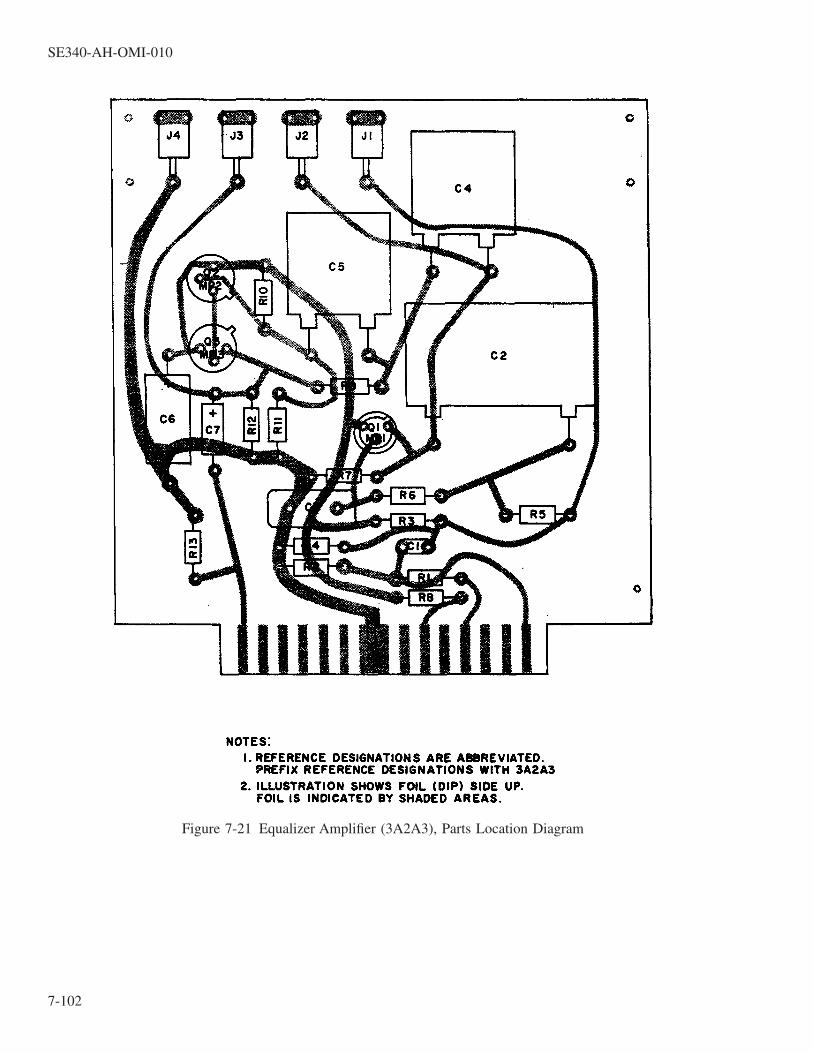
Figure 7-21 Equalizer Amplifier (3A2A3), Parts Location Diagram
SE340-AH-OMI-010
7-102

Figure 7-22 Test Oscillator (3A2A4), Parts Location Diagram
SE340-AH-OMI-010
7-103

Figure 7-23 Low Pass Filter (3A2A5), Parts Location Diagram
SE340-AH-OMI-010
7-104

Figure 7-24 Clipper Amplifier (3A2A6), Parts Location Diagram
SE340-AH-OMI-010
7-105

Figure 7-25 Balanced Demodulator Low (3A2A7), Parts Location Diagram
SE340-AH-OMI-010
7-106

Figure 7-26 Balanced Modulator (3A2A8), Parts Location Diagram
SE340-AH-OMI-010
7-107

Figure 7-27 Microphone Amplifier (3A2A9), Parts Location Diagram
SE340-AH-OMI-010
7-108
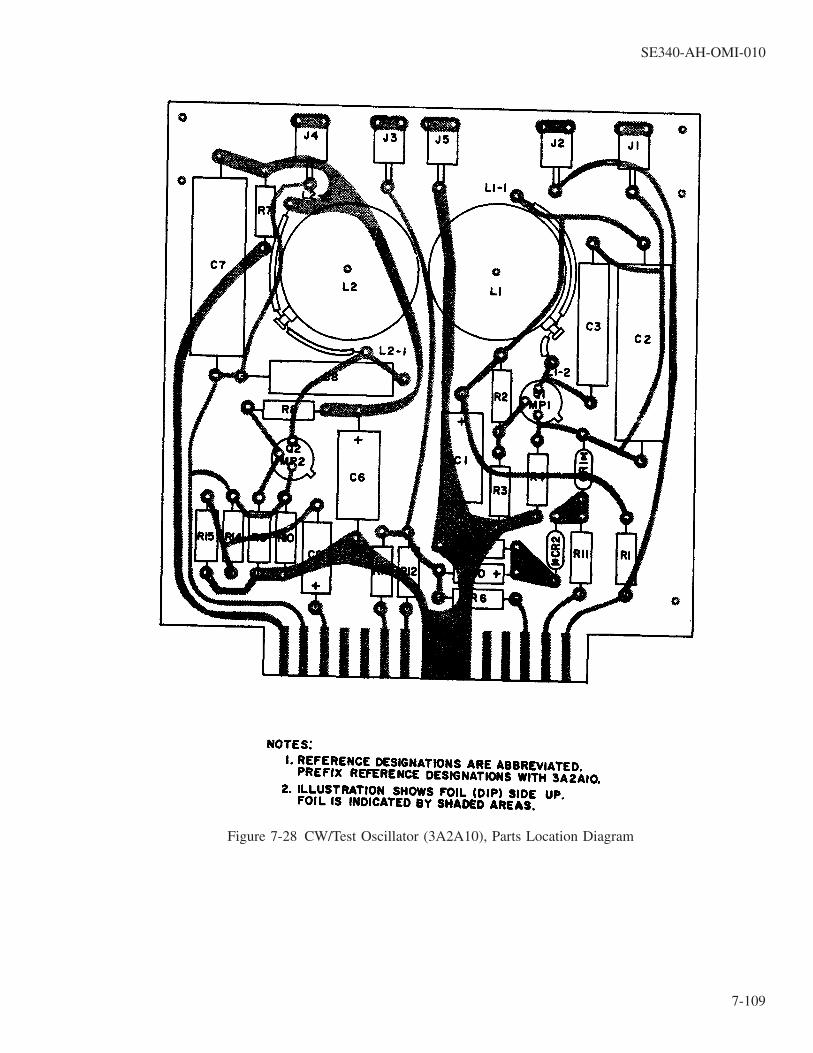
Figure 7-28 CW/Test Oscillator (3A2A10), Parts Location Diagram
SE340-AH-OMI-010
7-109

Figure 7-29 Low Frequency Receiver Amplifier (3A2A11), Parts Location Diagram
SE340-AH-OMI-010
7-110

Figure 7-30 Low Frequency Preamplifier Equalizer (3A2A12), Parts Location Diagram
SE340-AH-OMI-010
7-111

Figure 7-31 Balanced Demodulator High (3A2A13), Parts Location Diagram
SE340-AH-OMI-010
7-112

Figure 7-32 High Frequency Receiver Amplifier (3A2A14), Parts Location Diagram
SE340-AH-OMI-010
7-113

Figure 7-33 High Frequency Preamplifier Equalizer (3A2A15), Parts Location Diagram
SE340-AH-OMI-010
7-114

Figure 7-34 Summing Circuit (3A2A16), Parts Location Diagram
SE340-AH-OMI-010
7-115

Figure 7-35 Final Amplifier Assembly (3A3), Front View, Parts Location Diagram
SE340-AH-OMI-010
7-116

Figure 7-36 Final Amplifier Assembly (3A3), Top Interior View, Parts Location Diagram (Sheet 1 of 4)
SE340-AH-OMI-010
7-117

Figure 7-36 Final Amplifier Assembly (3A3), Top Interior View, Parts Location Diagram (Sheet 2 of 4)
SE340-AH-OMI-010
7-118

Figure 7-36 Final Amplifier Assembly (3A3), Top Interior View, Parts Location Diagram (Sheet 3 of 4)
SE340-AH-OMI-010
7-119

Figure 7-36 Final Amplifier Assembly (3A3), Top Interior View, Parts Location Diagram (Sheet 4 of 4)
SE340-AH-OMI-010
7-120

Figure 7-37 Final Amplifier Assembly (3A3), Bottom Interior View, Parts Location Diagram
SE340-AH-OMI-010
7-121

Figure 7-38 Low Level Final Amplifier (3A3A1), Parts Location Diagram
SE340-AH-OMI-010
7-122

Figure 7-39 Final Amplifier Protection Circuit (3A3A2), Parts Location Diagram
SE340-AH-OMI-010
7-123 / (7-124 Blank)

7-124@@FIpgtype@@BLANK@@!FIpgtype@@

CHAPTER 8
INSTALLATION
8-1. INTRODUCTION.
8-2. SCOPE.
This chapter contains instructions and data required for unpacking, installation, and initial checkout of SonarCommunication Set AN/WQC-2A (figure 1-1). These instructions are intended as a general guide to installationand pre-operational testing of the equipment, and are supplemental to the official Naval Sea Systems Commanddrawings, directives, and procedures which provide specific installation details for each ship or submarine.Troubleshooting data and procedures for equipment that may have been damaged in transit or during installationis not contained in this chapter. If equipment does not meet standards indicated in the pre-operational checkoutprocedure, refer to the troubleshooting information given in Chapter 5.
8-3. DIFFERENCES IN INSTALLATIONS.
The number and type of units installed in a typical system will vary, depending on the type of ship or sub-marine involved. For example, all installations will require a Receiver-Transmitter (Unit 3) and a Control Station(Unit 1). However, due to space limitations, certain installations will not require a Remote Control Station (Unit2). Similarly, surface vessels will require one each LF and HF transducers, while most submarines will be allot-ted one LF and three HF transducers (for the TOP, SAIL and BOTTOM hull locations).
8-4. OUTLINE AND DIMENSION DRAWINGS.
Outline and dimension drawings are given for each unit of the system, as follows:
a. Control Station, Unit 1 (figure 8-1).
b. Remote Control Station, Unit 2 (figure 8-2).
c. Receiver-Transmitter, Unit 3 (figure 8-3).
d. LF Transducer, Unit 4 (figure 8-4).
e. HF Transducer, Unit 4 (figure 8-5).
8-5. SITE CONSIDERATIONS.
8-6. GENERAL.
The exact locations in which units of the Sonar Communication Set are to be installed aboard ship will varyin terms of space available on different types of vessels. The actual location of each unit will be determined bythe installing activity. General factors that should be considered in the selection of sites include the following:
a. The operating units should be situated in positions where the microphones, controls and indicators are readilyaccessible to the operator.
b. The equipment layout should facilitate maintenance. Refer to the outline and dimension drawings supplied foreach unit of equipment. Note the allowances given for opening drawers and panels to their servicing position.
SE340-AH-OMI-010
8-1

c. Adequate ventilation space for heat dissipation must be provided for the Receiver-Transmitter (Unit 3).
8-7. CONTROL, SONAR COMMUNICATION SET C-7440A/WQC-2 (UNIT 1).
The Control Station contains a microphone, loudspeaker, headset outlet, and all controls used to operate thesystem after initial turn-on and checkout. Unit 1 is normally installed in, or adjacent to, the Combat InformationCenter (CIC) of the ship. Cable connections are made to the rear of the unit. All operating controls are mountedon the front panel. Access for servicing is made by release of the captive screws that secure the hinged frontpanel. Mounting holes are provided in the bottom of the unit for shelf or bracket mounting to a bulkhead. Referto the outline and dimension drawing of Unit 1 given in figure 8-1 for the exact dimensions.
8-8. CONTROL, SONAR COMMUNICATION SET C-7441A/WQC-2 (UNIT 2).
The Remote Control Station is not utilized in certain installations, such as submarines and some small sur-face ships. When installed, this unit provides a second station for transmission and reception at a separate loca-tion from Unit 1. A single cable connection is made to the rear of the unit. A loudspeaker volume control andheadset and microphone outlets are mounted on the front panel. Access for servicing is made by release of thecaptive screws that secure the hinged front panel. Mounting holes are provided in the bottom of the unit for shelfor bracket mounting to a bulkhead. Refer to the outline and dimension drawing of Unit 2 given in figure 8-2 forthe exact dimensions.
8-9. RECEIVER-TRANSMITTER RT-876A/WQC-2 (UNIT 3).
The Receiver-Transmitter is designed to be deck-mounted in a remote section of the ship, up to a maximumcable run of 350 feet from the Control Station (Unit 1). Refer to the outline and dimension drawing of Unit 3(figure 8-3) for the exact size and weight of the unit, location of lifting rings, and mounting hole dimensions. Allcable connections are made to the rear panel of unit 3. All operating and monitoring controls are located on thefront panel of the 3A1 Drawer Assembly. The drawer assemblies are designed to be pulled forward for mainte-nance, and may be pivoted up or down for access to the top or bottom of each drawer. Two air intake vents arelocated on the front of Unit 3. One air intake vent and three air exhaust vents are located on the rear panel. Thetwo access panels at the top left and right-hand sides of the unit are used only during manufacturing installation(or replacement during overhaul of Assembly 3A1 drawer slides. Access to these panels is not required duringnormal operation, maintenance or servicing of the equipment.
8-10. TRANSDUCER, SONAR TR-232/WQC-2 (UNIT 4) AND TR-233/WQC-2 (UNIT 5).
The two sonar transducers are designed to be mounted on the hull of the ship. The exact quantity and loca-tion of transducers required for each ship will be determined by the installing activity. Each vessel will have aminimum of one LF transducer (Unit 4) and one HF transducer (Unit 5). However, up to three HF transducersmay be installed on submarines, in different hull locations (top, sail and bottom). Refer to the outline and dimen-sion drawings for Unit 4 (figure 8-4) and Unit 5 (figure 8-5) for detailed mounting data.
8-10A. TRANSDUCER SUB-MODELS.
Both the TR-232 and TR-233 Transducer types have three (3) sub-models, any of which are compatible withthe AN/WQC-2A system. The TR-232, TR-233, TR-232A, and TR-233A come with attached cables. TheTR-232B and TR-233B are connectorized, utilizing separately supplied cable assemblies. The same cable assem-bly is used for both the TR-232B and TR-233B, and comes with the transducer mating plug already installed.Interconnection of the cable assemblies to the transducers is discussed in paragraph 8-10C. Figures 8-4 and 8-5illustrate the interconnection of both arrangements.
SE340-AH-OMI-010
8-2

8-10B. TRANSDUCER HANDLING PRECAUTIONS.
The following precautions are intended to protect both personnel and transducers from injury / damage dur-ing handling and installation. The transducers may be easily damaged from improper handling.
WARNING
Both transducers are very heavy; The larger TR-232/232A/232B weighsapproximately 440 lbs. Use extreme care when handling or moving thetransducers.
CAUTION
The ceramic elements within the transducers are very fragile and may beeasily damaged by improper handling. All handling precautions listed inparagraph 8-10B shall be followed.
a. Transducers must never be set or rolled on their rubber boot/transducer face(s).
b. Transducers must never be dropped, bounced, or bumped.
c. When lifting the TR-232/232A/232B transducer from the top, attach two eye-bolts to the existing 1-8UNC-2Athreaded mounting holes (6 locations available). Some installations may require lifting the transducer from thebottom; for these cases, attach the eye-bolts to the existing 3/4 -10UNC-2A threaded mounting holes (12 loca-tions available).
d. Some transducers come packaged with a sheet metal protective cover installed over the rubber boot. Whenprovided, this cover should be in place during all handling and installation operations. Remove cover for pre-installation testing and after completion of installation. All handling precautions shall be observed regardlessof whether a protective cover is provided or installed.
8-10C. TRANSDUCER/TRANSDUCER CABLE ASSEMBLY INTERCONNECTION. (FOR TR-232BAND TR-233B TRANSDUCERS ONLY)
CAUTION
Proper interconnection of the transducer and the transducer cable assemblyis critical to assuring the transducer’s water tight integrity. Failure to followthe interconnection instructions contained in paragraph 8-10C may result ina flooded, inoperable transducer.
a. Lightly coat Transducer Connecter O-Ring (MS28775-114) with silicone lubricant (MIL-S-8660). Always usea new O-Ring when attaching or reattaching a Transducer Cable Assembly to a Transducer.
b. Install new O-Rings into transducer and cable assembly connectors. See Figures 8-4 and 8-5 for location.
SE340-AH-OMI-010
8-3

c. While maintaining proper alignment between the pins on the two connectors, insert the cable assembly con-nector into the transducer connector.
d. Using a standard size (1½ to 2 inch) Spanner Wrench with a 0.130 diameter pin, tighten connector gland nutto between 12 and 16 ft.lbs. torque.
8-11. PRIMARY POWER REQUIREMENTS.
8-12.
A source of 115 VAC ± 10%, 60 Hz ± 6 Hz, single-phase power, 35-amperes maximum, is required foroperation of the equipment. This is connected by cable to connector 3J3 on the rear panel of the Receiver-Transmitter (Unit 3).
8-13. PRE-INSTALLATION ADJUSTMENTS.
8-14.
The equipment is designed to operate either with or without a Remote Control Station (Unit 2). To pre-adjustthe system for either configuration, two toggle switches are provided on a bracket located on the right interiorside of Control Station (Unit 1). Access to the switches is gained by releasing the front panel captive screws andswinging the panel downward.
a. If Unit 2 is not utilized for a given installation, set the UNIT 2 LOAD switch 1S10 to the ON position. Thisadds an additional load to the Unit 1 audio circuit which simulates the load of a Unit 2 speaker or headset.For installations where Unit 2 is utilized and connected to Unit 1, set this switch to the OFF position.
b. Installations utilizing Unit 2 will have two stations from which sonar voice transmissions may be originated.To avoid transmitting conflicts, OVERRIDE switch 1S11 is provided to establish voice transmitting priority.This switch may be set to either the UNIT 1 or UNIT 2 position, as determined by the particular requirementsfor a given ship. The position of this switch has no impact on system operation unless transmission is simul-taneously attempted from Units 1 and 2. Under these conditions, the transmission from the selected stationwill take priority.
8-15. PRE-INSTALLATION TRANSDUCER CHECKOUT.
A. The impedance should be checked for each transducer before it is installed to ensure that it has not beendamaged during shipment. The transducer must be immersed in water during, and for 24 hours prior to, thesetests in order for the results to be valid.
CAUTION
When checking transducers, do not apply DC voltages in excess of one voltin making resistance measurements across signal leads. Do not exceed ACvoltages of three volts rms across signal leads in making air measurements.
B. Connect the test equipment as shown in figure 8-6. This configuration is used for all transducer impedancechecks.
C. Test Low Frequency Transducer TR-232/232A/232B:
SE340-AH-OMI-010
8-4

1. Set switch to Position 1.
2. Set oscillator to a frequency of 1.5 ± 0.1 kHz and an output level of 1.0 ± 0.1 Vrms.
3. Set switch to Position 2. The AC voltmeter should read at least 15.0 mVrms.
4. Set switch to Position 1.
5. Set oscillator to a frequency of 2.1 ± 0.1 kHz and an output level of 1.0 ± 0.1 Vrms.
6. Set switch to Position 2. The AC voltmeter should read between 25.0 and 80.0 mVrms.
7. Set switch to Position 1.
8. Set oscillator to a frequency of 3.1 ± 0.1 kHz and an output level of 1.0 ± 0.1 Vrms.
9. Set switch to Position 2. The AC voltmeter should read at least 8.5 mVrms.
D. Test High Frequency Transducer TR-233/233A/233B:
1. Set switch to Position 1.
2. Set oscillator to a frequency of 9.3 ± 0.1 kHz and an output level of 1.0 ± 0.1 Vrms.
6. Set switch to Position 2. Adjust oscillator frequency, as required, between 9.0 and 9.6 kHz in order toobtain the maximum output level on the AC voltmeter.
7. The AC voltmeter should read between 25.0 and 80.0 mVrms.
8-16. INSTALLATION DRAWINGS.
8-17.
In addition to the five outline and dimension drawings, refer to the following installation drawings for addi-tional information on installation of the sonar communication set.
a. System cabling interconnection diagram (figure 8-7).
b. Cable running sheets (figure 8-8).
c. System drawing list (figure 8-9).
d. Summary list of installation material (figure 8-10).
8-18. INSTALLATION CHECK OUT.
8-19.
Refer to Table 5-6, Maintenance Turn-on Procedure, for the initial check out procedure, and to the availablegrooming and operation procedures for surface and submarine installations, as applicable.
SE340-AH-OMI-010
8-5 / (8-6 Blank)

8-6@@FIpgtype@@BLANK@@!FIpgtype@@

Figure 8-1 Control Station (Unit 1), Outline and Dimension Drawing
SE340-AH-OMI-010
8-7 / (8-8 Blank)

8-8@@FIpgtype@@BLANK@@!FIpgtype@@

Figure 8-2 Remote Control Station (Unit 2), Outline and Dimension Drawing
SE340-AH-OMI-010
8-9 / (8-10 Blank)

8-10@@FIpgtype@@BLANK@@!FIpgtype@@

1.
Figure 8-3 Receiver-Transmitter (Unit 3), Outline and Dimension Drawing
SE340-AH-OMI-010
8-11 / (8-12 Blank)

8-12@@FIpgtype@@BLANK@@!FIpgtype@@

Figure 8-4 LF Transducer (Unit 4), Outline and Dimension Drawing (Sheet 1 of 2)
SE340-AH-OMI-010
8-13

Figure 8-4 LF Transducer (Unit 4), Outline and Dimension Drawing (Sheet 2 of 2)
SE340-AH-OMI-010
8-14

Figure 8-5 HF Transducer (Unit 5), Outline and Dimension Drawing
SE340-AH-OMI-010
8-15

1.
Figure 8-6 Transducer Pre-Installation Test Setup
SE340-AH-OMI-010
8-16

Figure 8-7 System Cabling Interconnection Diagram
SE340-A
H-O
MI-010
8-17

Figure 8-8 Cable Running Sheets (Sheet 1 of 19)
SE340-AH-OMI-010
8-18

Figure 8-8 Cable Running Sheets (Sheet 2 of 19)
SE340-AH-OMI-010
8-19

Figure 8-8 Cable Running Sheets (Sheet 3 of 19)
SE340-AH-OMI-010
8-20

Figure 8-8 Cable Running Sheets (Sheet 4 of 19)
SE340-AH-OMI-010
8-21
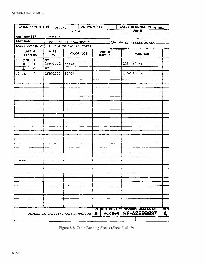
Figure 8-8 Cable Running Sheets (Sheet 5 of 19)
SE340-AH-OMI-010
8-22

Figure 8-8 Cable Running Sheets (Sheet 6 of 19)
SE340-AH-OMI-010
8-23

Figure 8-8 Cable Running Sheets (Sheet 7 of 19)
SE340-AH-OMI-010
8-24

Figure 8-8 Cable Running Sheets (Sheet 8 of 19)
SE340-AH-OMI-010
8-25

Figure 8-8 Cable Running Sheets (Sheet 9 of 19)
SE340-AH-OMI-010
8-26

Figure 8-8 Cable Running Sheets (Sheet 10 of 19)
SE340-AH-OMI-010
8-27

Figure 8-8 Cable Running Sheets (Sheet 11 of 19)
SE340-AH-OMI-010
8-28
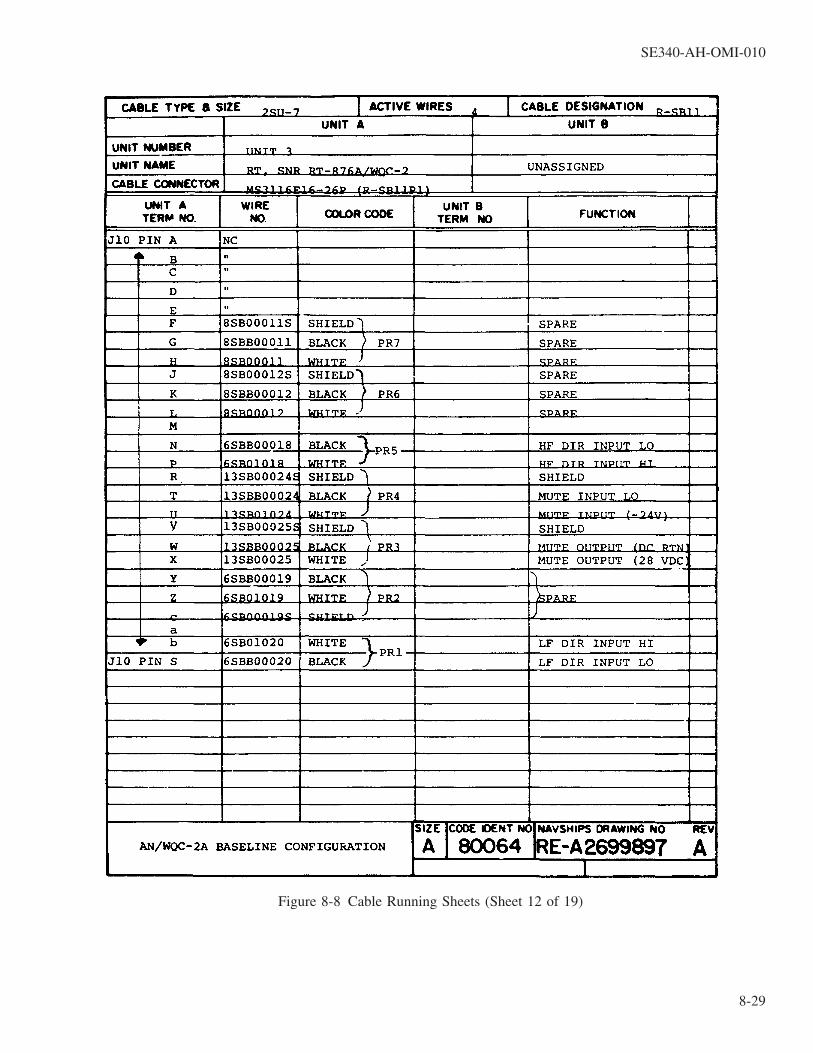
Figure 8-8 Cable Running Sheets (Sheet 12 of 19)
SE340-AH-OMI-010
8-29
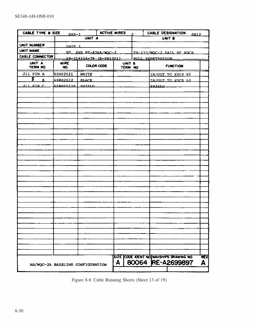
Figure 8-8 Cable Running Sheets (Sheet 13 of 19)
SE340-AH-OMI-010
8-30

Figure 8-8 Cable Running Sheets (Sheet 14 of 19)
SE340-AH-OMI-010
8-31

Figure 8-8 Cable Running Sheets (Sheet 15 of 19)
SE340-AH-OMI-010
8-32

Figure 8-8 Cable Running Sheets (Sheet 16 of 19)
SE340-AH-OMI-010
8-33

Figure 8-8 Cable Running Sheets (Sheet 17 of 19)
SE340-AH-OMI-010
8-34

Figure 8-8 Cable Running Sheets (Sheet 18 of 19)
SE340-AH-OMI-010
8-35

Figure 8-8 Cable Running Sheets (Sheet 19 of 19)
SE340-AH-OMI-010
8-36
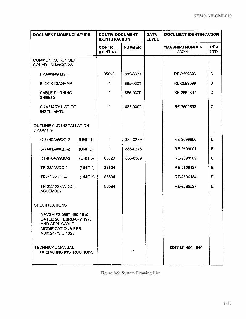
Figure 8-9 System Drawing List
SE340-AH-OMI-010
8-37

Figure 8-10 Summary List of Installation Material (Sheet 1 of 6)
SE340-AH-OMI-010
8-38
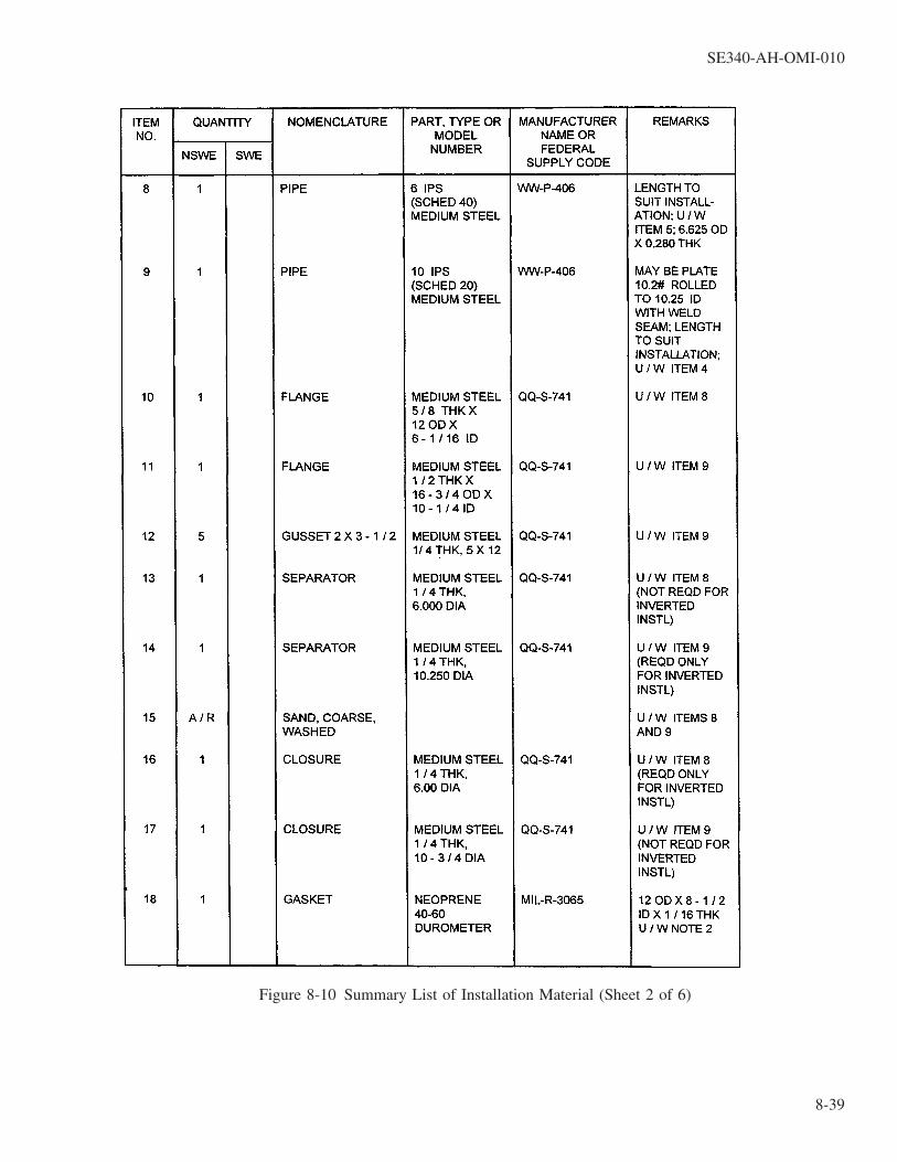
Figure 8-10 Summary List of Installation Material (Sheet 2 of 6)
SE340-AH-OMI-010
8-39
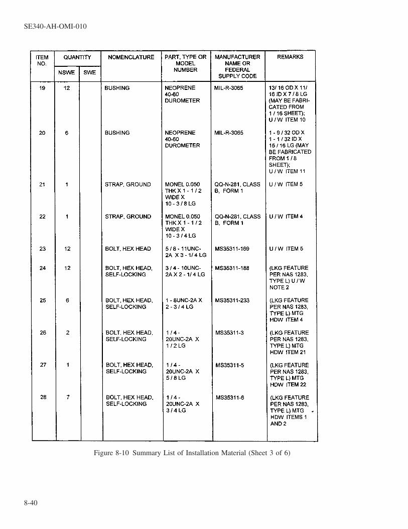
Figure 8-10 Summary List of Installation Material (Sheet 3 of 6)
SE340-AH-OMI-010
8-40

Figure 8-10 Summary List of Installation Material (Sheet 4 of 6)
SE340-AH-OMI-010
8-41

Figure 8-10 Summary List of Installation Material (Sheet 5 of 6)
SE340-AH-OMI-010
8-42

Figure 8-10 Summary List of Installation Material (Sheet 6 of 6)
SE340-AH-OMI-010
8-43 / (8-44 Blank)

8-44@@FIpgtype@@BLANK@@!FIpgtype@@

REAR SECTION
TECHNICAL MANUAL DEFICIENCY/EVALUATION REPORT (TMDER)
NOTE
Ships, training activities, supply points, depots, Naval Shipyards, and Supervi-sors of Shipbuilding are requested to arrange for the maximum practical use andevaluation of NAVSEA technical manuals. All errors, omissions, discrepancies,and suggestions for improvement to NAVSEA technical manuals shall be for-warded to:Commander,CODE 310 TMDER, BLDG 1388NAVSURFWARCENDIV NSDSA4363 MISSLE WAYPORT HUENEME CA 93043-4307on NAVSEA/SPAWAR Technical Manual Deficiency/Evaluation Report(TMDER), NAVSEA Form 4160/1. To facilitate such reporting, print, complete,and mail NAVSEA form 4160/1 below or submit TMDERS at web site:http://nsdsa.phdnswc.navy.mil/tmder/tmder.asp?lv1=1All feedback comments shall be thoroughly investigated and originators will beadvised of action resulting therefrom. Copies of NAVSEA Form 4160/1 may berequisitioned from the Naval Systems Data Support Activity Code 310 at theabove address.
TMDER / MAILER
SE340-AH-OMI-010
Rear-1 / (Rear-2 Blank)

Rear-2@@FIpgtype@@BLANK@@!FIpgtype@@