se7 cover layout 1 - wy & esther
TRANSCRIPT
Precast concrete panels • Becoming a sole practitioner consulting structural engineer •
Shard’s steel composite design • Structural design of The Icon Hotel in Dubai 89 (7) 5 April 2011
SE7 cover_Layout 1 31/03/2011 16:20 Page 1
The Structural Engineer 89 (7) 5 April 2011 3
The Institution of Structural EngineersRegistered CharityFounded 1908Incorporated by Royal Charter 1934
International HQ11 Upper Belgrave StreetLondon SW1X 8BHUnited Kingdomtel: + 44 ( 0 ) 20 7235 4535fax:+ 44 ( 0 ) 20 7235 [email protected]
PresidentRoger PlankBSc, PhD, CEng, FIStructE, MICE
Chief ExecutiveMartin Powell
Commercial and Communications DirectorPhil Williams
Managing EditorLee Baldwinemail: [email protected]: + 44 ( 0 ) 20 7201 9120fax:+ 44 ( 0 ) 20 7201 9109
Deputy EditorIan FarmerBSc ( Hons )email: [email protected]: + 44 ( 0 ) 20 7201 9121fax:+ 44 ( 0 ) 20 7201 9109
Art Editor & Design Co-ordinatorAdrian JacksonBA ( Hons )email: [email protected]: + 44 ( 0 ) 20 7201 9112fax:+ 44 ( 0 ) 20 7201 9109
Journal Editorial BoardCharles Banks - AECOM (UK)Peter Gardner - Southampton Solent University (UK)Geoff Harding - formerly with DCLGPeter Harris - formerly with Maunsell (now AECOM) (UK)Bill Harvey - Bill Harvey Associates Ltd (UK)Chris Jofeh - Ove Arup & Partners, Cardiff (UK)Allan Mann - Jacobs, Manchester (UK)Don McQuillan (Chairman) - RPS Group, Belfast (UK)Toby Mottram - University of Warwick (UK)Angus Palmer - Buro Happold, London (UK)Graham Pocock - WSP Cantor Seinuk (UK)Alastair Soane - Alastair Soane Consulting Ltd (UK)Bill Thompson
All editorial inquiries to:[email protected] ‘Notes for Authors’ available on journal website at: www.thestructuralengineer.org
All advertisement inquiries to:Advertisement ManagerSteve JacksonDipMStructural Promotions Ltd12 Lawrance Way, Thurlby,Bourne, Lincolnshire, PE10 0HUUnited Kingdomemail: [email protected]: + 44 ( 0 ) 1778 420 857fax:+ 44 ( 0 ) 1778 424 771
Published twice monthly by The Institution of Structural Engineers2011 subscription price (non-members):£280.00 (UK & international) including 100 years of free archiveSingle copy price: £18ISSN 1466-5123
News5 Editorial6 Introduction of deadlines for Technician
member applications...HSE reports ‘one in fourconstruction sites unsafe inNewcastle’...Preventing hazard risk - anindustry challenge
8 The Big Bang Fair 2011...Japan earthquakeand tsunami
10 Site manager sentenced after worker exposedto asbestos...Concrete dome home receivesacclaim in inaugural invention awards
Features12 Precast concrete panels: Imperial Wharf and
The Bodleian’s Book Storage Facility
13 40, 50 and 60 years of Institution membership
16 Viewpoint: Becoming a sole practitioner consulting structural engineer Lawrence Gottlieb
19 Shard’s steel composite design breaks records in speed and height
5 April 2011www.thestructuralengineer.org
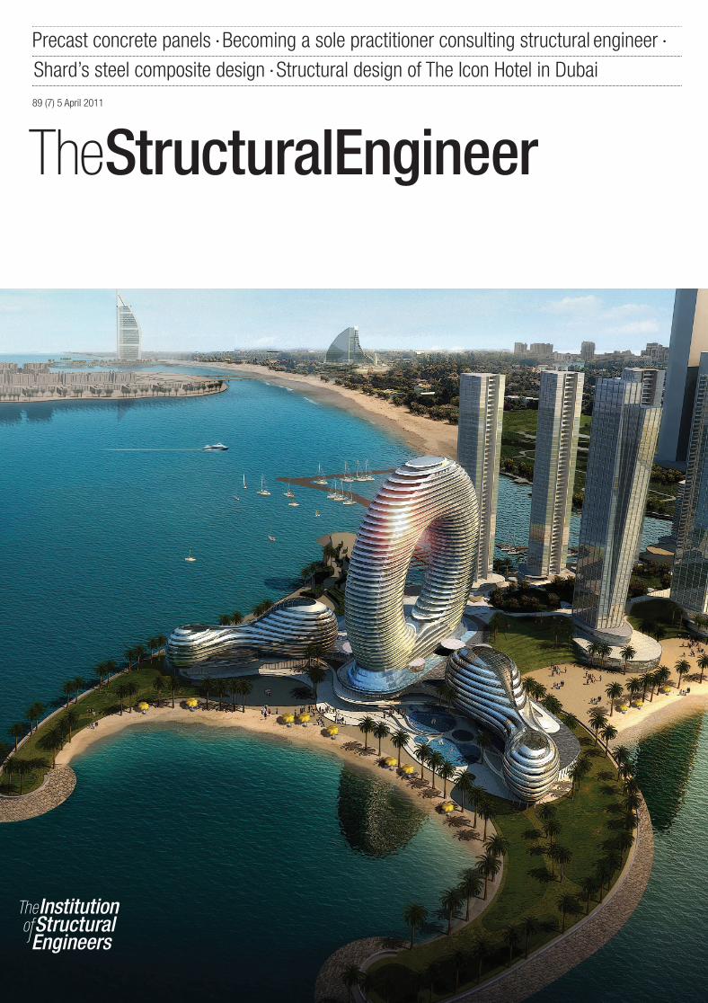
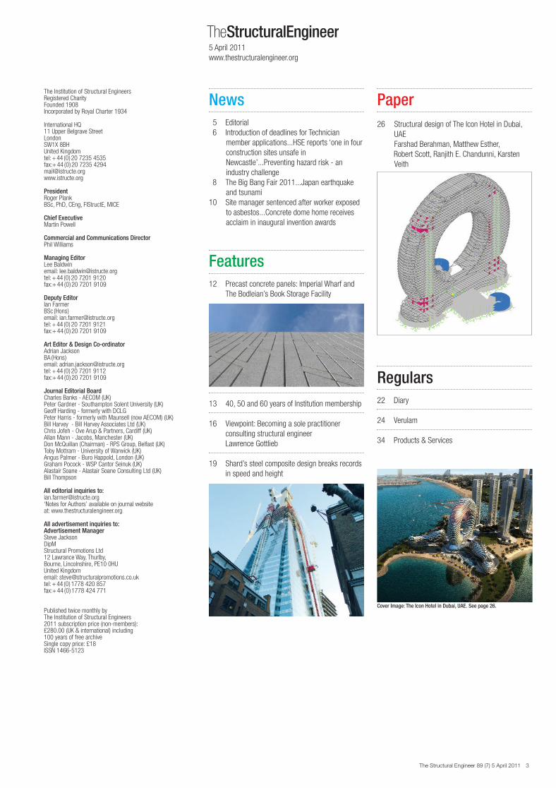
Cover Image: The Icon Hotel in Dubai, UAE. See page 26.
Paper26 Structural design of The Icon Hotel in Dubai,
UAEFarshad Berahman, Matthew Esther,Robert Scott, Ranjith E. Chandunni, KarstenVeith
Regulars22 Diary
24 Verulam
34 Products & Services
SE7 contents_Layout 3 31/03/2011 16:26 Page 3
26 The Structural Engineer 89 (7) 5 April 2011
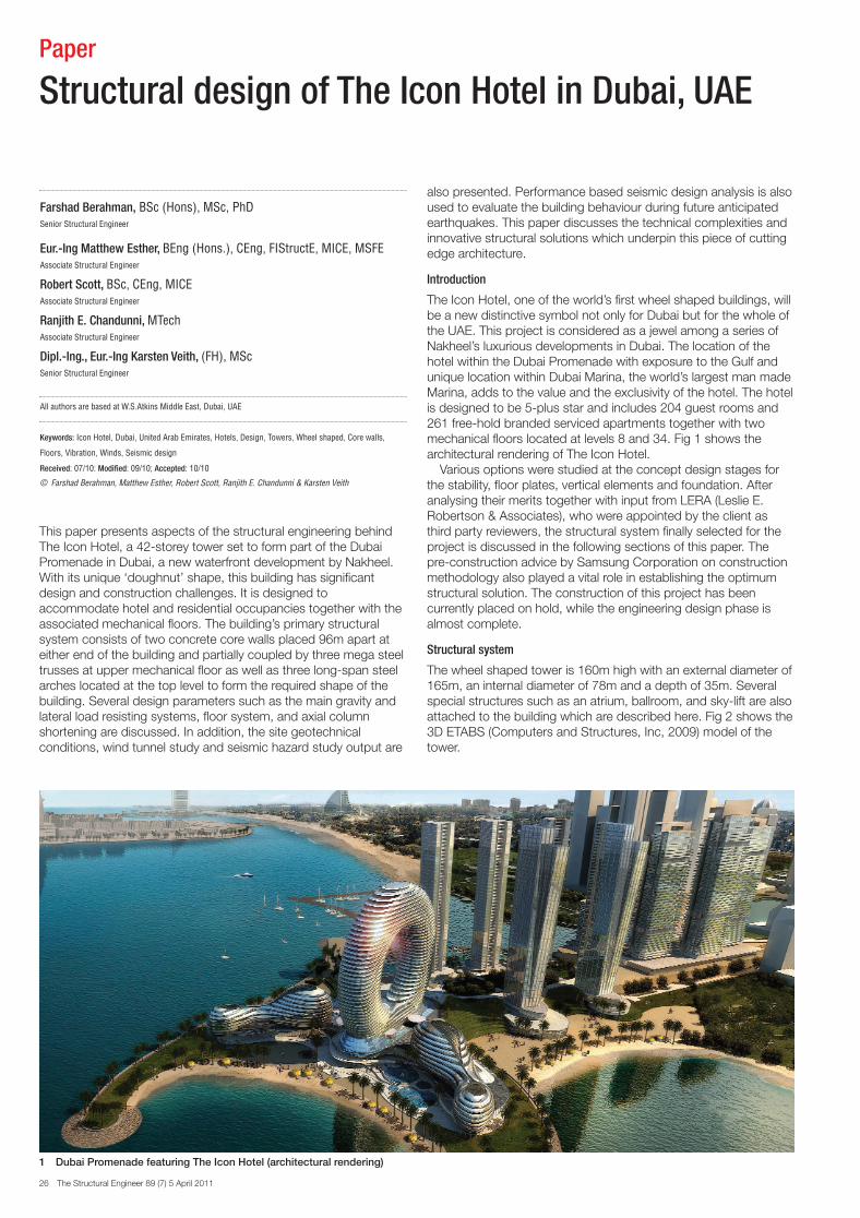
This paper presents aspects of the structural engineering behindThe Icon Hotel, a 42-storey tower set to form part of the DubaiPromenade in Dubai, a new waterfront development by Nakheel.With its unique ‘doughnut’ shape, this building has significantdesign and construction challenges. It is designed toaccommodate hotel and residential occupancies together with theassociated mechanical floors. The building’s primary structuralsystem consists of two concrete core walls placed 96m apart ateither end of the building and partially coupled by three mega steeltrusses at upper mechanical floor as well as three long-span steelarches located at the top level to form the required shape of thebuilding. Several design parameters such as the main gravity andlateral load resisting systems, floor system, and axial columnshortening are discussed. In addition, the site geotechnicalconditions, wind tunnel study and seismic hazard study output are
also presented. Performance based seismic design analysis is alsoused to evaluate the building behaviour during future anticipatedearthquakes. This paper discusses the technical complexities andinnovative structural solutions which underpin this piece of cuttingedge architecture.
Introduction
The Icon Hotel, one of the world’s first wheel shaped buildings, willbe a new distinctive symbol not only for Dubai but for the whole ofthe UAE. This project is considered as a jewel among a series ofNakheel’s luxurious developments in Dubai. The location of thehotel within the Dubai Promenade with exposure to the Gulf andunique location within Dubai Marina, the world’s largest man madeMarina, adds to the value and the exclusivity of the hotel. The hotelis designed to be 5-plus star and includes 204 guest rooms and261 free-hold branded serviced apartments together with twomechanical floors located at levels 8 and 34. Fig 1 shows thearchitectural rendering of The Icon Hotel.
Various options were studied at the concept design stages forthe stability, floor plates, vertical elements and foundation. Afteranalysing their merits together with input from LERA (Leslie E.Robertson & Associates), who were appointed by the client asthird party reviewers, the structural system finally selected for theproject is discussed in the following sections of this paper. Thepre-construction advice by Samsung Corporation on constructionmethodology also played a vital role in establishing the optimumstructural solution. The construction of this project has beencurrently placed on hold, while the engineering design phase isalmost complete.
Structural system
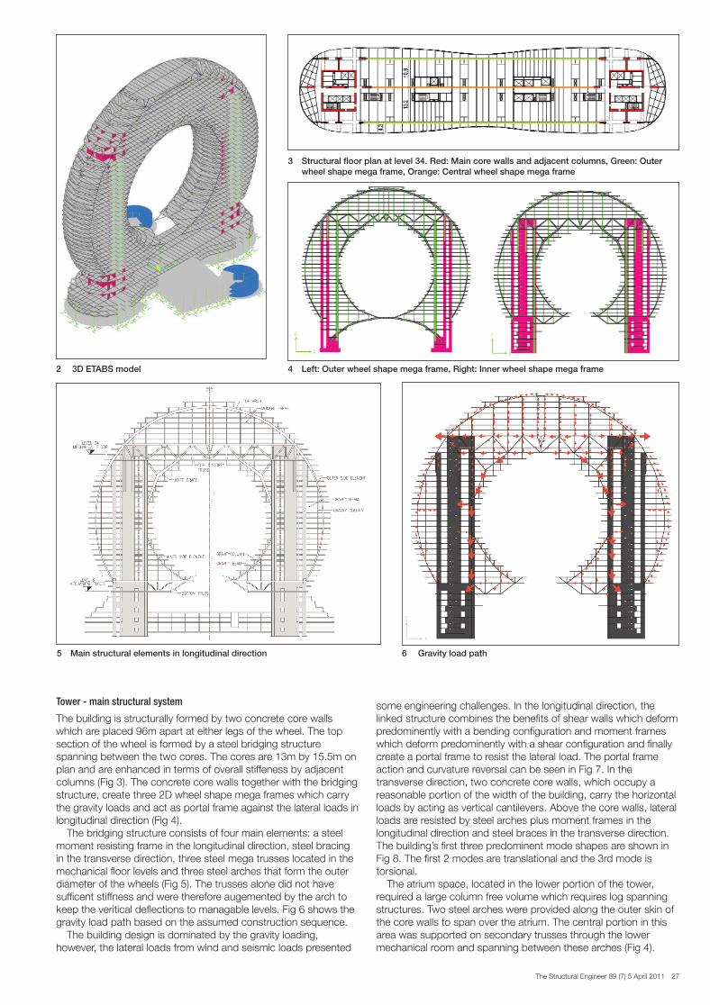
The wheel shaped tower is 160m high with an external diameter of165m, an internal diameter of 78m and a depth of 35m. Severalspecial structures such as an atrium, ballroom, and sky-lift are alsoattached to the building which are described here. Fig 2 shows the3D ETABS (Computers and Structures, Inc, 2009) model of thetower.
Paper
Structural design of The Icon Hotel in Dubai, UAE
Farshad Berahman, BSc (Hons), MSc, PhDSenior Structural Engineer
Eur.-Ing Matthew Esther, BEng (Hons.), CEng, FIStructE, MICE, MSFEAssociate Structural Engineer
Robert Scott, BSc, CEng, MICEAssociate Structural Engineer
Ranjith E. Chandunni, MTechAssociate Structural Engineer
Dipl.-Ing., Eur.-Ing Karsten Veith, (FH), MSc Senior Structural Engineer
All authors are based at W.S.Atkins Middle East, Dubai, UAE
Keywords: Icon Hotel, Dubai, United Arab Emirates, Hotels, Design, Towers, Wheel shaped, Core walls,
Floors, Vibration, Winds, Seismic design
Received: 07/10: Modified: 09/10; Accepted: 10/10
© Farshad Berahman, Matthew Esther, Robert Scott, Ranjith E. Chandunni & Karsten Veith
1 Dubai Promenade featuring The Icon Hotel (architectural rendering)
SE7 Paper - Icon Hotel Dubai_Layout 3 01/04/2011 10:25 Page 26
The Structural Engineer 89 (7) 5 April 2011 27
Tower - main structural system
The building is structurally formed by two concrete core wallswhich are placed 96m apart at either legs of the wheel. The topsection of the wheel is formed by a steel bridging structurespanning between the two cores. The cores are 13m by 15.5m onplan and are enhanced in terms of overall stiffeness by adjacentcolumns (Fig 3). The concrete core walls together with the bridgingstructure, create three 2D wheel shape mega frames which carrythe gravity loads and act as portal frame against the lateral loads inlongitudinal direction (Fig 4).
The bridging structure consists of four main elements: a steelmoment resisting frame in the longitudinal direction, steel bracingin the transverse direction, three steel mega trusses located in themechanical floor levels and three steel arches that form the outerdiameter of the wheels (Fig 5). The trusses alone did not havesufficent stiffness and were therefore augemented by the arch tokeep the veritical deflections to managable levels. Fig 6 shows thegravity load path based on the assumed construction sequence.
The building design is dominated by the gravity loading,however, the lateral loads from wind and seismic loads presented
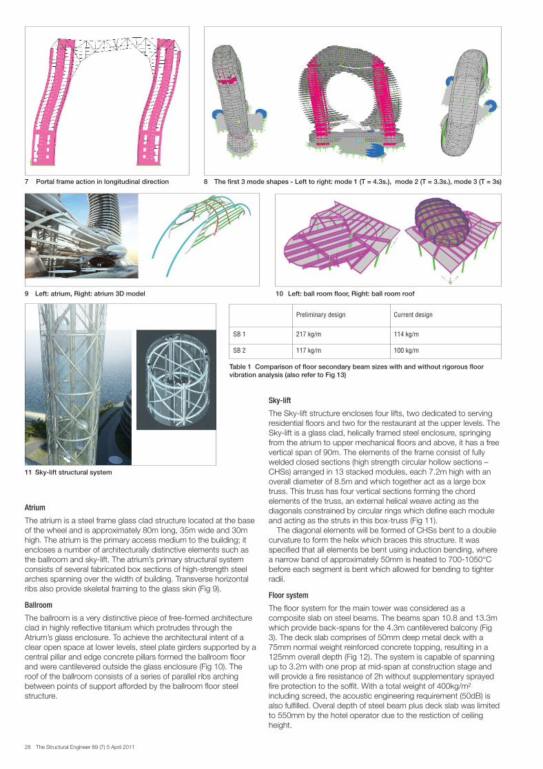
some engineering challenges. In the longitudinal direction, thelinked structure combines the benefits of shear walls which deformpredominently with a bending configuration and moment frameswhich deform predominently with a shear configuration and finallycreate a portal frame to resist the lateral load. The portal frameaction and curvature reversal can be seen in Fig 7. In thetransverse direction, two concrete core walls, which occupy areasonable portion of the width of the building, carry the horizontalloads by acting as vertical cantilevers. Above the core walls, lateralloads are resisted by steel arches plus moment frames in thelongitudinal direction and steel braces in the transverse direction.The building’s first three predominent mode shapes are shown inFig 8. The first 2 modes are translational and the 3rd mode istorsional.
The atrium space, located in the lower portion of the tower,required a large column free volume which requires log spanningstructures. Two steel arches were provided along the outer skin ofthe core walls to span over the atrium. The central portion in thisarea was supported on secondary trusses through the lowermechanical room and spanning between these arches (Fig 4).
4 Left: Outer wheel shape mega frame, Right: Inner wheel shape mega frame2 3D ETABS model
3 Structural floor plan at level 34. Red: Main core walls and adjacent columns, Green: Outer wheel shape mega frame, Orange: Central wheel shape mega frame
6 Gravity load path 5 Main structural elements in longitudinal direction
SE7 Paper - Icon Hotel Dubai_Layout 3 01/04/2011 10:26 Page 27
28 The Structural Engineer 89 (7) 5 April 2011
Atrium
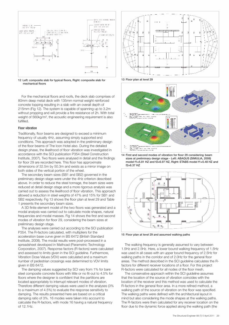
The atrium is a steel frame glass clad structure located at the baseof the wheel and is approximately 80m long, 35m wide and 30mhigh. The atrium is the primary access medium to the building; itencloses a number of architecturally distinctive elements such asthe ballroom and sky-lift. The atrium’s primary structural systemconsists of several fabricated box sections of high-strength steelarches spanning over the width of building. Transverse horizontalribs also provide skeletal framing to the glass skin (Fig 9).
Ballroom
The ballroom is a very distinctive piece of free-formed architectureclad in highly reflective titanium which protrudes through theAtrium’s glass enclosure. To achieve the architectural intent of aclear open space at lower levels, steel plate girders supported by acentral pillar and edge concrete pillars formed the ballroom floorand were cantilevered outside the glass enclosure (Fig 10). Theroof of the ballroom consists of a series of parallel ribs archingbetween points of support afforded by the ballroom floor steelstructure.
Sky-lift
The Sky-lift structure encloses four lifts, two dedicated to servingresidential floors and two for the restaurant at the upper levels. TheSky-lift is a glass clad, helically framed steel enclosure, springingfrom the atrium to upper mechanical floors and above, it has a freevertical span of 90m. The elements of the frame consist of fullywelded closed sections (high strength circular hollow sections –CHSs) arranged in 13 stacked modules, each 7.2m high with anoverall diameter of 8.5m and which together act as a large boxtruss. This truss has four vertical sections forming the chordelements of the truss, an external helical weave acting as thediagonals constrained by circular rings which define each moduleand acting as the struts in this box-truss (Fig 11).
The diagonal elements will be formed of CHSs bent to a doublecurvature to form the helix which braces this structure. It wasspecified that all elements be bent using induction bending, wherea narrow band of approximately 50mm is heated to 700-1050°Cbefore each segment is bent which allowed for bending to tighterradii.
Floor system
The floor system for the main tower was considered as acomposite slab on steel beams. The beams span 10.8 and 13.3mwhich provide back-spans for the 4.3m cantilevered balcony (Fig3). The deck slab comprises of 50mm deep metal deck with a75mm normal weight reinforced concrete topping, resulting in a125mm overall depth (Fig 12). The system is capable of spanningup to 3.2m with one prop at mid-span at construction stage andwill provide a fire resistance of 2h without supplementary sprayedfire protection to the soffit. With a total weight of 400kg/m²including screed, the acoustic engineering requirement (50dB) isalso fulfilled. Overal depth of steel beam plus deck slab was limitedto 550mm by the hotel operator due to the restiction of ceilingheight.
7 Portal frame action in longitudinal direction
Table 1 Comparison of floor secondary beam sizes with and without rigorous floor vibration analysis (also refer to Fig 13)
Preliminary design Current design
SB 1 217 kg/m 114 kg/m
SB 2 117 kg/m 100 kg/m
8 The first 3 mode shapes - Left to right: mode 1 (T = 4.3s.), mode 2 (T = 3.3s.), mode 3 (T = 3s)
9 Left: atrium, Right: atrium 3D model 10 Left: ball room floor, R ight: ball room roof
11 Sky-lift structural system
SE7 Paper - Icon Hotel Dubai_Layout 3 01/04/2011 10:26 Page 28
The Structural Engineer 89 (7) 5 April 2011 29
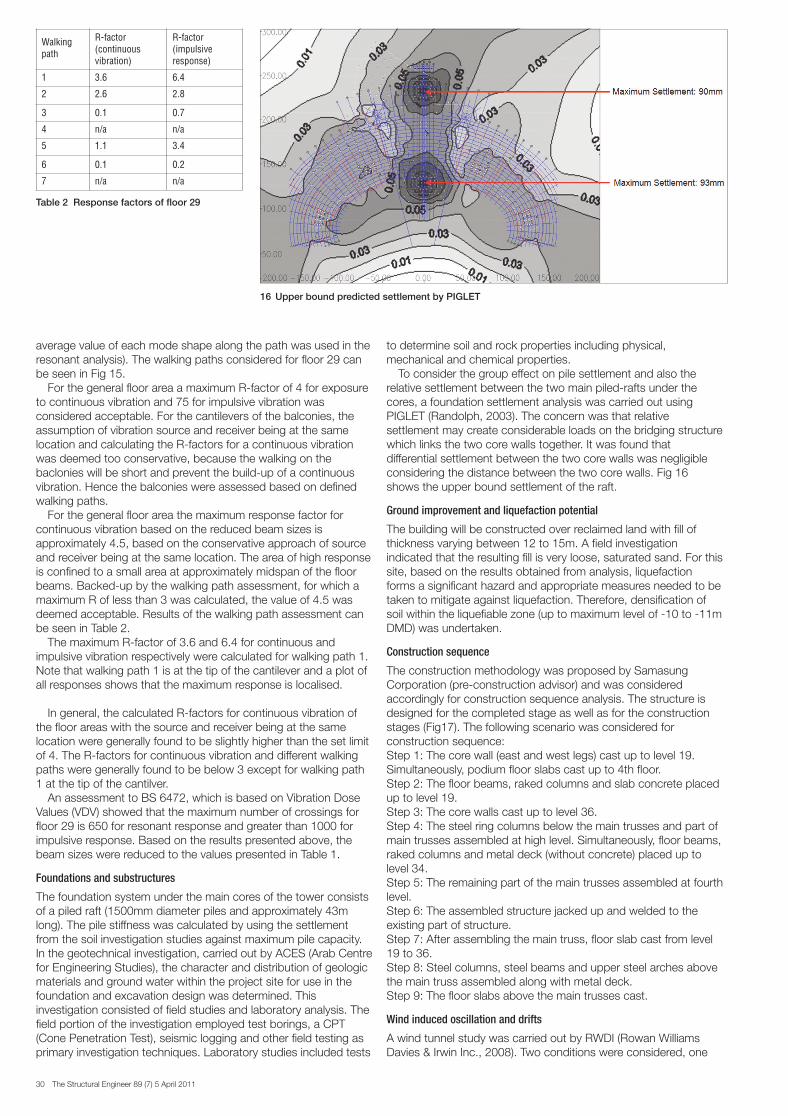
For the mechanical floors and roofs, the deck slab comprises of80mm deep metal deck with 135mm normal weight reinforcedconcrete topping resulting in a slab with an overall depth of215mm (Fig 12). The system is capable of spanning up to 3.2mwithout propping and will provide a fire resistance of 2h. With totalweight of 560kg/m², the acoustic engineering requirement is alsofulfilled.
Floor vibration
Traditionally, floor beams are designed to exceed a minimumfrequency of usually 4Hz, assuming simply supported endconditions. This approach was adopted in the preliminary designof the floor beams of The Icon Hotel also. During the detaileddesign phase, the likelihood of floor vibration was investigated inaccordance with the SCI publication P354 (Steel ConstructionInstitute, 2007). Two floors were analysed in detail and the findingsfor floor 29 are recorded here. This floor has approximatedimensions of 32.5m by 50.3m and exists as a mirror image onboth sides of the vertical portion of the wheel.
The secondary beam sizes (SB1 and SB2) governed in thepreliminary design stage were under the 4Hz criterion describedabove. In order to reduce the steel tonnage, the beam sizes werereduced at detail design stage and a more rigorous analysis wascarried out to assess the likelihood of floor vibration. This approachallowed a reduction in steel weights of 47% and 15% for SB1 andSB2 respectively. Fig 13 shows the floor plan at level 29 and Table1 presents the secondary beam sizes.
A 3D finite element model of the two floors was generated and amodal analysis was carried out to calculate mode shapes, naturalfrequencies and modal masses. Fig 14 shows the first and secondmodes of vibration for floor 29, considering the beam sizes atpreliminary design stage.
The analyses were carried out according to the SCI publicationP354. The R-factors calculated, with multipliers for theacceleration base curve given in BS 6472 (British StandardInstitute, 2008). The modal results were post-processed in aspreadsheet developed in Mathcad (Parametric TechnologyCorporation, 2007). Response factors (R-factors) were calculatedand assessed to limits given in the SCI guideline. Furthermore,Vibration Dose Values (VDV) were calculated and a maximumnumber of pedestrian crossings was determined to VDV limitsgiven in BS 6472.
The damping values suggested by SCI vary from 1% for baresteel composite concrete floors with little or no fit-out to 4.5% forfloors where the designer is confident that the partitions arelocated appropriately to interrupt relevant modes of vibration.Therefore different damping values were used in the analyses (3%to a maximum of 4.5%) to evaluate the response sensitivity todamping. The results presented here are based on a criticaldamping ratio of 3%. 16 modes were taken into account tocalculate the R-factors, with mode 16 having a natural frequencyof 12.1Hz.
The walking frequency is generally assumed to vary between1.5Hz and 2.5Hz. Here, a lower bound walking frequency of 1.5Hzwas used in all cases with an upper bound frequency of 2.5Hz forwalking paths in the corridor and of 2.0Hz for the general floorareas. The method described in the SCI guideline calculates the R-factors for different receiver locations of a floor. For this projectR-factors were calculated for all nodes of the floor mesh.
The conservative approach within the SCI guideline assumesthat the location of the source of vibration coincides with thelocation of the receiver and this method was used to calculate theR-factors in the general floor area. In a more refined method, awalking path of the source of vibration on the floor was specified.The walking paths were defined with the architectural layout inmind but also considering the mode shapes at the walking paths.The R-factors were then calculated for any receiver location on thefloor due to the dynamic force applied along the walking path (the
12 Left: composite slab for typical floors, Right: composite slab formechanical floors
15 Floor plan at level 29 and assumed walking paths
13 Floor plan at level 29
14 First and second modes of vibration for floor 29 considering beam sizes at preliminary design stage - Left: ABAQUS (SIMULIA, 2008) model f1=5.81 HZ and f2=6.97 HZ, Right: ETABS model f1=5.48 HZ and f2=6.37 HZ
SE7 Paper - Icon Hotel Dubai_Layout 3 01/04/2011 10:26 Page 29
30 The Structural Engineer 89 (7) 5 April 2011
average value of each mode shape along the path was used in theresonant analysis). The walking paths considered for floor 29 canbe seen in Fig 15.
For the general floor area a maximum R-factor of 4 for exposureto continuous vibration and 75 for impulsive vibration wasconsidered acceptable. For the cantilevers of the balconies, theassumption of vibration source and receiver being at the samelocation and calculating the R-factors for a continuous vibrationwas deemed too conservative, because the walking on thebaclonies will be short and prevent the build-up of a continuousvibration. Hence the balconies were assessed based on definedwalking paths.
For the general floor area the maximum response factor forcontinuous vibration based on the reduced beam sizes isapproximately 4.5, based on the conservative approach of sourceand receiver being at the same location. The area of high responseis confined to a small area at approximately midspan of the floorbeams. Backed-up by the walking path assessment, for which amaximum R of less than 3 was calculated, the value of 4.5 wasdeemed acceptable. Results of the walking path assessment canbe seen in Table 2.
The maximum R-factor of 3.6 and 6.4 for continuous andimpulsive vibration respectively were calculated for walking path 1.Note that walking path 1 is at the tip of the cantilever and a plot ofall responses shows that the maximum response is localised.
In general, the calculated R-factors for continuous vibration ofthe floor areas with the source and receiver being at the samelocation were generally found to be slightly higher than the set limitof 4. The R-factors for continuous vibration and different walkingpaths were generally found to be below 3 except for walking path1 at the tip of the cantilver.
An assessment to BS 6472, which is based on Vibration DoseValues (VDV) showed that the maximum number of crossings forfloor 29 is 650 for resonant response and greater than 1000 forimpulsive response. Based on the results presented above, thebeam sizes were reduced to the values presented in Table 1.
Foundations and substructures
The foundation system under the main cores of the tower consistsof a piled raft (1500mm diameter piles and approximately 43mlong). The pile stiffness was calculated by using the settlementfrom the soil investigation studies against maximum pile capacity.In the geotechnical investigation, carried out by ACES (Arab Centrefor Engineering Studies), the character and distribution of geologicmaterials and ground water within the project site for use in thefoundation and excavation design was determined. Thisinvestigation consisted of field studies and laboratory analysis. Thefield portion of the investigation employed test borings, a CPT(Cone Penetration Test), seismic logging and other field testing asprimary investigation techniques. Laboratory studies included tests
to determine soil and rock properties including physical,mechanical and chemical properties.
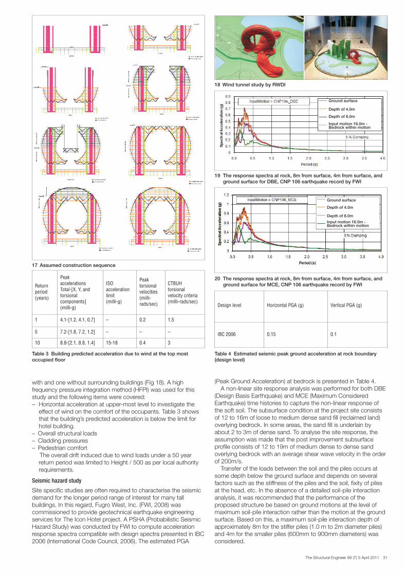
To consider the group effect on pile settlement and also therelative settlement between the two main piled-rafts under thecores, a foundation settlement analysis was carried out usingPIGLET (Randolph, 2003). The concern was that relativesettlement may create considerable loads on the bridging structurewhich links the two core walls together. It was found thatdifferential settlement between the two core walls was negligibleconsidering the distance between the two core walls. Fig 16shows the upper bound settlement of the raft.
Ground improvement and liquefaction potential
The building will be constructed over reclaimed land with fill ofthickness varying between 12 to 15m. A field investigationindicated that the resulting fill is very loose, saturated sand. For thissite, based on the results obtained from analysis, liquefactionforms a significant hazard and appropriate measures needed to betaken to mitigate against liquefaction. Therefore, densification ofsoil within the liquefiable zone (up to maximum level of -10 to -11mDMD) was undertaken.
Construction sequence
The construction methodology was proposed by SamasungCorporation (pre-construction advisor) and was consideredaccordingly for construction sequence analysis. The structure isdesigned for the completed stage as well as for the constructionstages (Fig17). The following scenario was considered forconstruction sequence:Step 1: The core wall (east and west legs) cast up to level 19.Simultaneously, podium floor slabs cast up to 4th floor. Step 2: The floor beams, raked columns and slab concrete placedup to level 19.Step 3: The core walls cast up to level 36.Step 4: The steel ring columns below the main trusses and part ofmain trusses assembled at high level. Simultaneously, floor beams,raked columns and metal deck (without concrete) placed up tolevel 34.Step 5: The remaining part of the main trusses assembled at fourthlevel. Step 6: The assembled structure jacked up and welded to theexisting part of structure.Step 7: After assembling the main truss, floor slab cast from level19 to 36.Step 8: Steel columns, steel beams and upper steel arches abovethe main truss assembled along with metal deck.Step 9: The floor slabs above the main trusses cast.
Wind induced oscillation and drifts
A wind tunnel study was carried out by RWDI (Rowan WilliamsDavies & Irwin Inc., 2008). Two conditions were considered, one
16 Upper bound predicted settlement by PIGLET
Table 2 Response factors of floor 29
Walkingpath
R-factor(continuousvibration)
R-factor(impulsiveresponse)
1 3.6 6.4
2 2.6 2.8
3 0.1 0.7
4 n/a n/a
5 1.1 3.4
6 0.1 0.2
7 n/a n/a
SE7 Paper - Icon Hotel Dubai_Layout 3 01/04/2011 10:26 Page 30
The Structural Engineer 89 (7) 5 April 2011 31
with and one without surrounding buildings (Fig 18). A highfrequency pressure integration method (HFPI) was used for thisstudy and the following items were covered:– Horizontal acceleration at upper-most level to investigate the
effect of wind on the comfort of the occupants. Table 3 shows that the building’s predicted acceleration is below the limit for hotel building.
– Overall structural loads– Cladding pressures– Pedestrian comfort
The overall drift induced due to wind loads under a 50 year return period was limited to Height / 500 as per local authority requirements.
Seismic hazard study
Site specific studies are often required to characterise the seismicdemand for the longer period range of interest for many tallbuildings. In this regard, Fugro West, Inc. (FWI, 2008) wascommissioned to provide geotechnical earthquake engineeringservices for The Icon Hotel project. A PSHA (Probabilistic SeismicHazard Study) was conducted by FWI to compute accelerationresponse spectra compatible with design spectra presented in IBC2006 (International Code Council, 2006). The estimated PGA
(Peak Ground Acceleration) at bedrock is presented in Table 4.A non-linear site response analysis was performed for both DBE
(Design Basis Earthquake) and MCE (Maximum ConsideredEarthquake) time histories to capture the non-linear response ofthe soft soil. The subsurface condition at the project site consistsof 12 to 16m of loose to medium dense sand fill (reclaimed land)overlying bedrock. In some areas, the sand fill is underlain byabout 2 to 3m of dense sand. To analyse the site response, theassumption was made that the post improvement subsurfaceprofile consists of 12 to 19m of medium dense to dense sandoverlying bedrock with an average shear wave velocity in the orderof 200m/s.
Transfer of the loads between the soil and the piles occurs atsome depth below the ground surface and depends on severalfactors such as the stiffness of the piles and the soil, fixity of pilesat the head, etc. In the absence of a detailed soil-pile interactionanalysis, it was recommended that the performance of theproposed structure be based on ground motions at the level ofmaximum soil-pile interaction rather than the motion at the groundsurface. Based on this, a maximum soil-pile interaction depth ofapproximately 8m for the stiffer piles (1.0 m to 2m diameter piles)and 4m for the smaller piles (600mm to 900mm diameters) wasconsidered.
19 The response spectra at rock, 8m from surface, 4m from surface, andground surface for DBE, CNP 106 earthquake record by FWI
20 The response spectra at rock, 8m from surface, 4m from surface, andground surface for MCE, CNP 106 earthquake record by FWI
Table 3 Building predicted acceleration due to wind at the top most occupied floor
Returnperiod(years)
PeakaccelerationsTotal-[X, Y, andtorsionalcomponents](milli-g)
ISOaccelerationlimit(milli-g)
Peaktorsionalvelocities(milli-rads/sec)
CTBUHtorsionalvelocity criteria(milli-rads/sec)
1 4.1-[1.2, 4.1, 0.7] – 0.2 1.5
5 7.2-[1.8, 7.2, 1.2] – – –
10 8.8-[2.1, 8.8, 1.4] 15-18 0.4 3
Table 4 Estimated seismic peak ground acceleration at rock boundary (design level)
Design level Horizontal PGA (g) Vertical PGA (g)
IBC 2006 0.15 0.1
17 Assumed construction sequence
18 Wind tunnel study by RWDI
Ground surface
Depth of 4.0m
Depth of 8.0m
Input motion 16.0m - Bedrock within motion
Ground surface
Depth of 4.0m
Depth of 8.0m
Input motion 16.0m - Bedrock within motion
SE7 Paper - Icon Hotel Dubai_Layout 3 01/04/2011 10:26 Page 31
32 The Structural Engineer 89 (7) 5 April 2011
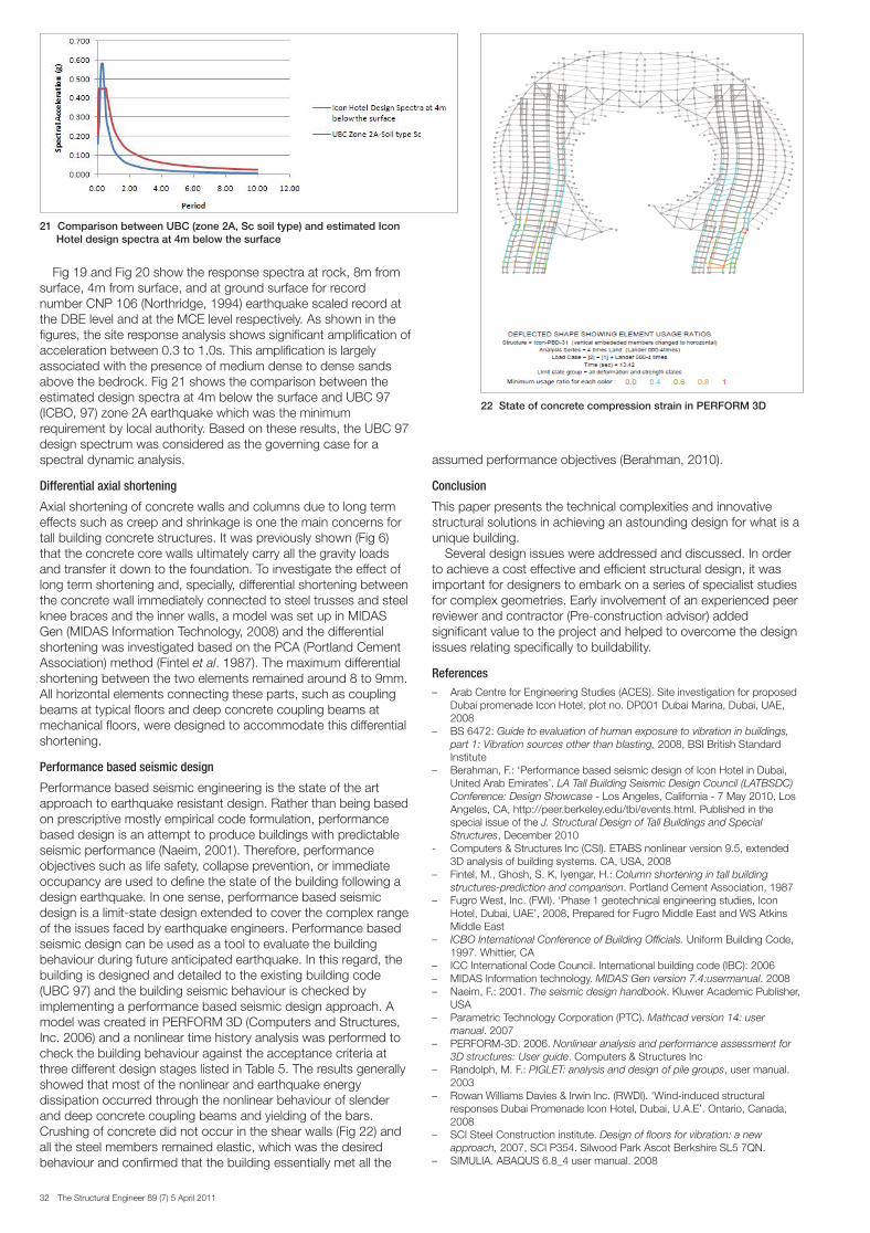
Fig 19 and Fig 20 show the response spectra at rock, 8m fromsurface, 4m from surface, and at ground surface for recordnumber CNP 106 (Northridge, 1994) earthquake scaled record atthe DBE level and at the MCE level respectively. As shown in thefigures, the site response analysis shows significant amplification ofacceleration between 0.3 to 1.0s. This amplification is largelyassociated with the presence of medium dense to dense sandsabove the bedrock. Fig 21 shows the comparison between theestimated design spectra at 4m below the surface and UBC 97(ICBO, 97) zone 2A earthquake which was the minimumrequirement by local authority. Based on these results, the UBC 97design spectrum was considered as the governing case for aspectral dynamic analysis.
Differential axial shortening
Axial shortening of concrete walls and columns due to long termeffects such as creep and shrinkage is one the main concerns fortall building concrete structures. It was previously shown (Fig 6)that the concrete core walls ultimately carry all the gravity loadsand transfer it down to the foundation. To investigate the effect oflong term shortening and, specially, differential shortening betweenthe concrete wall immediately connected to steel trusses and steelknee braces and the inner walls, a model was set up in MIDASGen (MIDAS Information Technology, 2008) and the differentialshortening was investigated based on the PCA (Portland CementAssociation) method (Fintel et al. 1987). The maximum differentialshortening between the two elements remained around 8 to 9mm.All horizontal elements connecting these parts, such as couplingbeams at typical floors and deep concrete coupling beams atmechanical floors, were designed to accommodate this differentialshortening.
Performance based seismic design
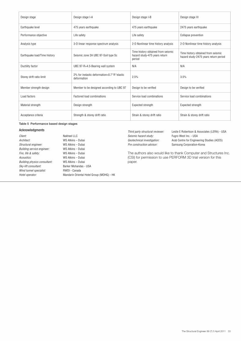
Performance based seismic engineering is the state of the artapproach to earthquake resistant design. Rather than being basedon prescriptive mostly empirical code formulation, performancebased design is an attempt to produce buildings with predictableseismic performance (Naeim, 2001). Therefore, performanceobjectives such as life safety, collapse prevention, or immediateoccupancy are used to define the state of the building following adesign earthquake. In one sense, performance based seismicdesign is a limit-state design extended to cover the complex rangeof the issues faced by earthquake engineers. Performance basedseismic design can be used as a tool to evaluate the buildingbehaviour during future anticipated earthquake. In this regard, thebuilding is designed and detailed to the existing building code(UBC 97) and the building seismic behaviour is checked byimplementing a performance based seismic design approach. Amodel was created in PERFORM 3D (Computers and Structures,Inc. 2006) and a nonlinear time history analysis was performed tocheck the building behaviour against the acceptance criteria atthree different design stages listed in Table 5. The results generallyshowed that most of the nonlinear and earthquake energydissipation occurred through the nonlinear behaviour of slenderand deep concrete coupling beams and yielding of the bars.Crushing of concrete did not occur in the shear walls (Fig 22) andall the steel members remained elastic, which was the desiredbehaviour and confirmed that the building essentially met all the
assumed performance objectives (Berahman, 2010).
Conclusion
This paper presents the technical complexities and innovativestructural solutions in achieving an astounding design for what is aunique building.
Several design issues were addressed and discussed. In orderto achieve a cost effective and efficient structural design, it wasimportant for designers to embark on a series of specialist studiesfor complex geometries. Early involvement of an experienced peerreviewer and contractor (Pre-construction advisor) addedsignificant value to the project and helped to overcome the designissues relating specifically to buildability.
References– Arab Centre for Engineering Studies (ACES). Site investigation for proposed
Dubai promenade Icon Hotel, plot no. DP001 Dubai Marina, Dubai, UAE,2008
– BS 6472: Guide to evaluation of human exposure to vibration in buildings,part 1: Vibration sources other than blasting, 2008, BSI British StandardInstitute
– Berahman, F.: ‘Performance based seismic design of Icon Hotel in Dubai,United Arab Emirates’. LA Tall Building Seismic Design Council (LATBSDC)Conference: Design Showcase - Los Angeles, California - 7 May 2010, LosAngeles, CA, http://peer.berkeley.edu/tbi/events.html. Published in thespecial issue of the J. Structural Design of Tall Buildings and SpecialStructures, December 2010
- Computers & Structures Inc (CSI). ETABS nonlinear version 9.5, extended3D analysis of building systems. CA, USA, 2008
– Fintel, M., Ghosh, S. K, Iyengar, H.: Column shortening in tall buildingstructures-prediction and comparison. Portland Cement Association, 1987
– Fugro West, Inc. (FWI). ‘Phase 1 geotechnical engineering studies, IconHotel, Dubai, UAE’, 2008, Prepared for Fugro Middle East and WS AtkinsMiddle East
– ICBO International Conference of Building Officials. Uniform Building Code,1997. Whittier, CA
– ICC International Code Council. International building code (IBC): 2006 – MIDAS Information technology. MIDAS Gen version 7.4:usermanual. 2008– Naeim, F.: 2001. The seismic design handbook. Kluwer Academic Publisher,
USA– Parametric Technology Corporation (PTC). Mathcad version 14: user
manual. 2007– PERFORM-3D. 2006. Nonlinear analysis and performance assessment for
3D structures: User guide. Computers & Structures Inc– Randolph, M. F.: PIGLET: analysis and design of pile groups, user manual.
2003– Rowan Williams Davies & Irwin Inc. (RWDI). ‘Wind-induced structural
responses Dubai Promenade Icon Hotel, Dubai, U.A.E’. Ontario, Canada,2008
– SCI Steel Construction institute. Design of floors for vibration: a newapproach, 2007, SCI P354. Silwood Park Ascot Berkshire SL5 7QN.
– SIMULIA. ABAQUS 6.8_4 user manual. 2008
22 State of concrete compression strain in PERFORM 3D
21 Comparison between UBC (zone 2A, Sc soil type) and estimated Icon Hotel design spectra at 4m below the surface
SE7 Paper - Icon Hotel Dubai_Layout 3 01/04/2011 10:26 Page 32
The Structural Engineer 89 (7) 5 April 2011 33
Acknowledgments
Client: Nakheel LLC Architect: WS Atkins – DubaiStructural engineer: WS Atkins – DubaiBuilding service engineer: WS Atkins – DubaiFire, life & safety: WS Atkins – DubaiAcoustics: WS Atkins – DubaiBuilding physics consultant: WS Atkins – DubaiSky-lift consultant: Barker Mohandas - USAWind tunnel specialist: RWDI - CanadaHotel operator: Mandarin Oriental Hotel Group (MOHG) - HK
Third party structural reviewer: Leslie E Robertson & Associates (LERA) - USASeismic hazard study: Fugro West Inc. - USAGeotechnical investigation: Arab Centre for Engineering Studies (ACES)Pre construction advisor: Samsung Corporation-Korea
The authors also would like to thank Computer and Structures Inc.(CSI) for permission to use PERFORM 3D trial version for thispaper.
Table 5 Performance based design stages
Design stage Design stage I-A Design stage I-B Design stage III
Earthquake level 475 years earthquake 475 years earthquake 2475 years earthquake
Performance objective Life safety Life safety Collapse prevention
Analysis type 3-D linear response spectrum analysis 2-D Nonlinear time history analysis 2-D Nonlinear time history analysis
Earthquake load/Time history Seismic zone 2A UBC 97-Soil type ScTime history obtained from seismichazard study-475 years returnperiod
Time history obtained from seismichazard study-2475 years return period
Ductility factor UBC 97-R=4.5-Bearing wall system N/A N/A
Storey drift ratio limit2% for inelastic deformation=0.7*R*elasticdeformation 2.5% 3.5%
Member strength design Member to be designed according to UBC 97 Design to be verified Design to be verified
Load factors Factored load combinations Service load combinations Service load combinations
Material strength Design strength Expected strength Expected strength
Acceptance criteria Strength & storey drift ratio Strain & storey drift ratio Strain & storey drift ratio
SE7 Paper - Icon Hotel Dubai_Layout 3 05/04/2011 13:37 Page 33