sea wave energy converter wave dragon …bambus.iel.waw.pl/pliki/ogolne/prace iel/231/01.pdf ·...
TRANSCRIPT

Marian KAŹMIERKOWSKI, Marek JASIŃSKI Mariusz MALINOWSKI, Tadeusz PŁATEK Sebastian STYŃSKI, Patrycjusz ANTONIEWICZ Wojciech KOŁOMYJSKI, Dariusz ŚWIERCZYŃSKI Hans Ch. SOERENSEN, Erik FRIIS-MADSEN Lars CHRISTIANSEN, Wilfried KNAPP Zhongfu ZHOU, Petar IGIC
SEA WAVE ENERGY CONVERTER − WAVE DRAGON MW FOR FEW MEGAWATTS
POWER RANGE
ABSTRACT The paper has as an objective to combine and disseminate a brief knowledge on generators and power electronics for Wave Dragon MW (WDMW) Power Take Off system. Wave Dragon MW captures power from sea waves by means of low-head turbines and converts it into rotating mechanical power.
Prof. Marian KAŹMIERKOWSKI,
Marek JASIŃSKI, Ph.D., Mariusz MALINOWSKI, Ph.D., Tadeusz PŁATEK, Ph.D., Sebastian STYŃSKI, M.Sc., Patrycjusz ANTONIEWICZ, M.Sc.,
Wojciech KOŁOMYJSKI, M.Sc. Wydział Elektryczny, ISEP Politechnika Warszawska
Dariusz ŚWIERCZYŃSKI, Ph.D. Wydział Inżynierii Produkcji
Szkoła Główna Gospodarstwa Wiejskiego
Hans Ch. SOERENSEN, Ph.D., Erik FRIIS-MADSEN, Ph.D., Lars CHRISTIANSEN, M.Sc. Wave Dragon APS and LTD
Wilfried KNAPP, Ph.D. Lehrstuhl fuer Fluidmechanik,
Technische Universitaet Muenchen
Zhongfu ZHOU, Ph.D., Petar IGIC, Ph.D. Swansea University
PROCEEDINGS OF ELECTROTECHNICAL INSTITUTE, Issue 231, 2007

M. Kaźmierkowski, M. Jasiński, M. Malinowski, T. Płatek, S. Styński, ...
6
In recent years because of energy saving problem on almost whole world power electronics and electric machines as well as renewable energy market has been intensively developed.
Problems which can appear in conversion mechanical power to electrical power in WDMW can be expected to be similar as in wind turbine. Therefore, state of the art briefly can base on state of the art for wind turbines. However, subject of the mechanical energy conversion from sea waves to electrical energy is not well identified and further research should be curried out.
Keywords: Renewable energy, energy form sea waves, power electronics converters, generators
1. INTRODUCTION L. H. Hansen at al. proposed philosophy which should be considered in wind turbine design process. Line connection demands can be defined objectively; therefore it should be base in choosing a solution for power conversion system. Sketch of this philosophy is shown in Fig. 1.
Market demandsManufacture philosophy
Consistent system solution
Function requirement
Demands to technology
Demands to control strategy
Fig. 1. Philosophy which should be considered [2]

Sea wave energy converter – Wave Dragon MW for few megawatts power range
7
Technological road map for renewable energy conversion can be presented as in Fig. 2. Some solutions from that overview could be interesting and applicable for sea wave energy conversion. Therefore, in the paper brief considerations are presented.
Fig. 2. Technological road map for renewable energy conversion [3]. Some solution could be interesting and applicable for sea wave energy conversion 2. RENEWABLE SEA WAVES ENERGY SYSTEM WAVE DRAGON – MW Needs for the development of renewable energy, including offshore wave energy, arises from the requirement to strengthen the security of supply, reduce emissions of greenhouse and acid rain gases. As an example the UK
M. Kaźmierkowski, M. Jasiński, M. Malinowski, T. Płatek, S. Styński, ...
8
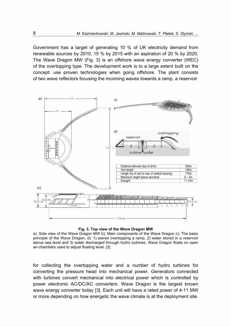
Government has a target of generating 10 % of UK electricity demand from renewable sources by 2010, 15 % by 2015 with an aspiration of 20 % by 2020. The Wave Dragon MW (Fig. 3) is an offshore wave energy converter (WEC) of the overtopping type. The development work is to a large extent built on the concept: use proven technologies when going offshore. The plant consists of two wave reflectors focusing the incoming waves towards a ramp, a reservoir
Fig. 3. Top view of the Wave Dragon MW a); Side view of the Wave Dragon MW b); Main components of the Wave Dragon c); The basic principle of the Wave Dragon, d): 1) waves overtopping a ramp, 2) water stored in a reservoir above sea level and 3) water discharged through hydro turbines. Wave Dragon floats on open air-chambers used to adjust floating level. [3] for collecting the overtopping water and a number of hydro turbines for converting the pressure head into mechanical power. Generators connected with turbines convert mechanical into electrical power which is controlled by power electronic AC/DC/AC converters. Wave Dragon is the largest known wave energy converter today [3]. Each unit will have a rated power of 4-11 MW or more depending on how energetic the wave climate is at the deployment site.
Sea wave energy converter – Wave Dragon MW for few megawatts power range
9
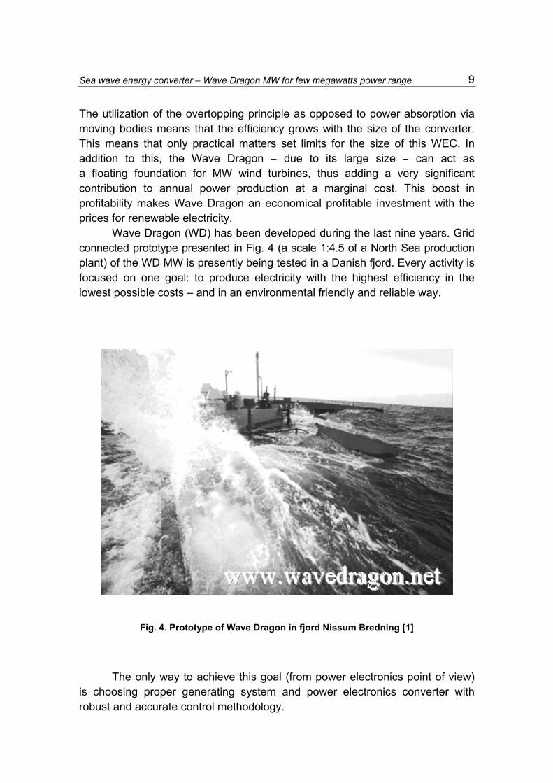
The utilization of the overtopping principle as opposed to power absorption via moving bodies means that the efficiency grows with the size of the converter. This means that only practical matters set limits for the size of this WEC. In addition to this, the Wave Dragon − due to its large size − can act as a floating foundation for MW wind turbines, thus adding a very significant contribution to annual power production at a marginal cost. This boost in profitability makes Wave Dragon an economical profitable investment with the prices for renewable electricity. Wave Dragon (WD) has been developed during the last nine years. Grid connected prototype presented in Fig. 4 (a scale 1:4.5 of a North Sea production plant) of the WD MW is presently being tested in a Danish fjord. Every activity is focused on one goal: to produce electricity with the highest efficiency in the lowest possible costs – and in an environmental friendly and reliable way.
Fig. 4. Prototype of Wave Dragon in fjord Nissum Bredning [1]
The only way to achieve this goal (from power electronics point of view) is choosing proper generating system and power electronics converter with robust and accurate control methodology.
M. Kaźmierkowski, M. Jasiński, M. Malinowski, T. Płatek, S. Styński, ...
10
The Wave Dragon is an overtopping wave energy converter in which the waves are running up a slope and are filling a reservoir above the mean sea level. In the full scale device, the potential energy of the water in the reservoir will be exploited using 16 low head hydro turbines. Depending on the sea state (defined by the significant wave height averaged over an interval of 15 mins), the initial crest height (defined as the crest height of the device with the reservoir filled to the minimum level) will be set to the respective optimum value between 0.80 m and 3.50 m. The generator is defined by its design power Pn = 290 kW at n = 250 rpm.
The generator may be a permanent magnet synchronous generator (PMSG) or an asynchronous induction generator (IG). Two criteria will be controllability and efficiency at part load, as the turbines will operate between 50 and 150 kW power for most of the time.
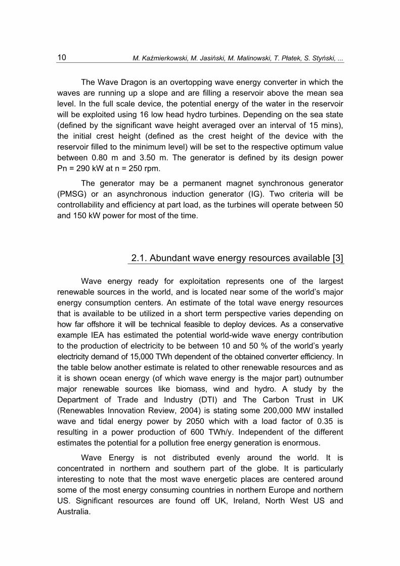
2.1. Abundant wave energy resources available [3] Wave energy ready for exploitation represents one of the largest renewable sources in the world, and is located near some of the world’s major energy consumption centers. An estimate of the total wave energy resources that is available to be utilized in a short term perspective varies depending on how far offshore it will be technical feasible to deploy devices. As a conservative example IEA has estimated the potential world-wide wave energy contribution to the production of electricity to be between 10 and 50 % of the world’s yearly electricity demand of 15,000 TWh dependent of the obtained converter efficiency. In the table below another estimate is related to other renewable resources and as it is shown ocean energy (of which wave energy is the major part) outnumber major renewable sources like biomass, wind and hydro. A study by the Department of Trade and Industry (DTI) and The Carbon Trust in UK (Renewables Innovation Review, 2004) is stating some 200,000 MW installed wave and tidal energy power by 2050 which with a load factor of 0.35 is resulting in a power production of 600 TWh/y. Independent of the different estimates the potential for a pollution free energy generation is enormous.
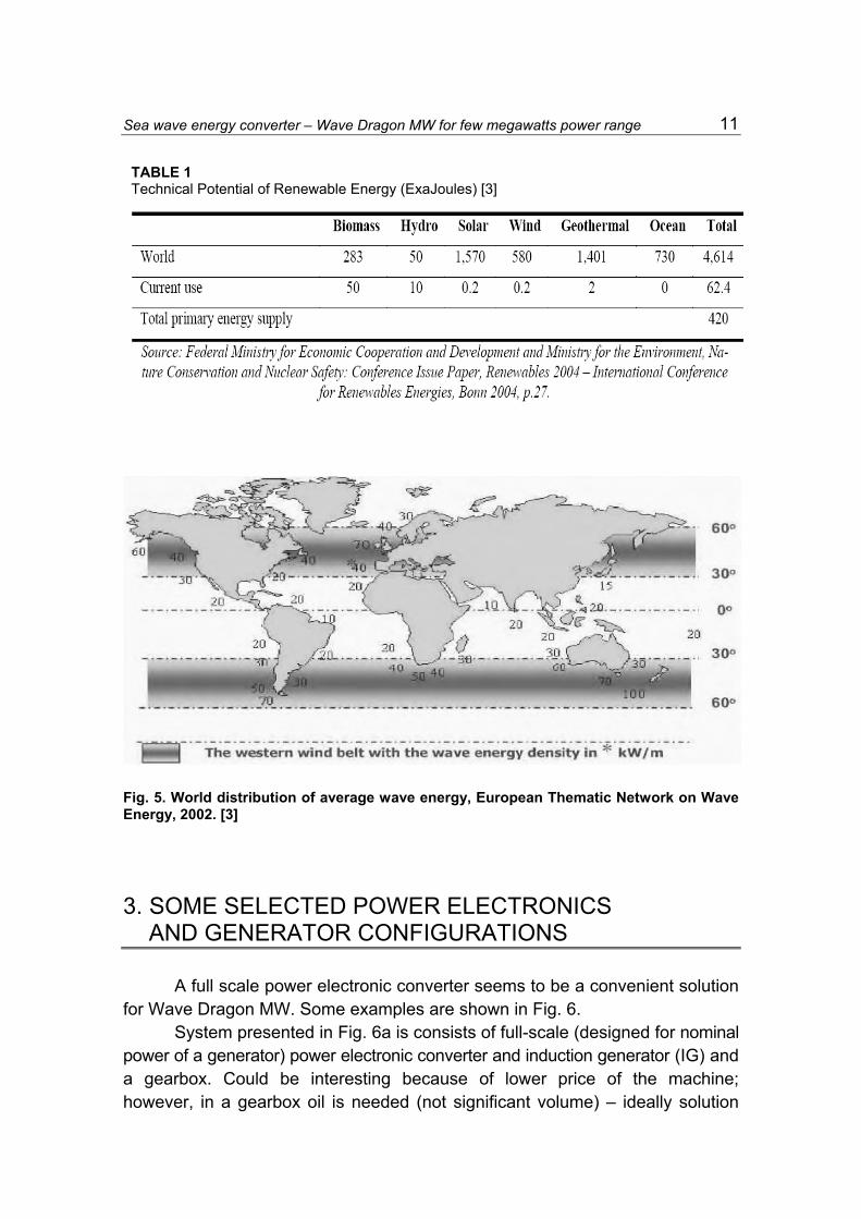
Wave Energy is not distributed evenly around the world. It is concentrated in northern and southern part of the globe. It is particularly interesting to note that the most wave energetic places are centered around some of the most energy consuming countries in northern Europe and northern US. Significant resources are found off UK, Ireland, North West US and Australia.
Sea wave energy converter – Wave Dragon MW for few megawatts power range
11
TABLE 1 Technical Potential of Renewable Energy (ExaJoules) [3]
Fig. 5. World distribution of average wave energy, European Thematic Network on Wave Energy, 2002. [3] 3. SOME SELECTED POWER ELECTRONICS AND GENERATOR CONFIGURATIONS A full scale power electronic converter seems to be a convenient solution for Wave Dragon MW. Some examples are shown in Fig. 6.
System presented in Fig. 6a is consists of full-scale (designed for nominal power of a generator) power electronic converter and induction generator (IG) and a gearbox. Could be interesting because of lower price of the machine; however, in a gearbox oil is needed (not significant volume) – ideally solution

M. Kaźmierkowski, M. Jasiński, M. Malinowski, T. Płatek, S. Styński, ...
12
should be oil less. Moreover, a gearbox in drive train gives additional moment of inertia. This solution is less robust then case without gearbox. IG is a high-speed generator; therefore its weight and cost are reduced.
Fig. 6. Turbine system with full-scale power electronic converter with: a) Induction Generator (IG) and gearbox; b) Permanent Magnet Synchronous Generator (PMSG) and gearbox; c) Multi-pole Permanent Magnet Synchronous Generator (PMSG). This solution is preferred for Wave Dragon MW d) overall symbol of MODULE A
Solutions given in Fig. 6b, c could operate with transistors based Line Side Converter (LSG) and transistor based Generator Side Converter (GSC). However, it should be pointed that GSC can be constructed based on diode rectifier and step-up chopper in DC-link or based on half-bridge converter. In Fig. 6b PMSG is a high-speed generator; therefore its weight and cost are reduced as well. In this case efficiency would be increased (compared to system presented in Fig. 6a) because permanent magnets for excitation – these generators do not need additional excitation current. This case needs a gearbox as well; therefore all drawback of a gearbox is valid.
Figure 6c presents PMSG which is a low-speed generator (multi-pole); therefore its weight and cost are increased. However, efficiency could be increased because permanent magnets for excitation and gearbox less operation. This solution is not a cheapest one, but seems to be most convenient for Wave Dragon MW.
3.1. Some solution for groups of the renewable
energy sources on Wave Dragon MW
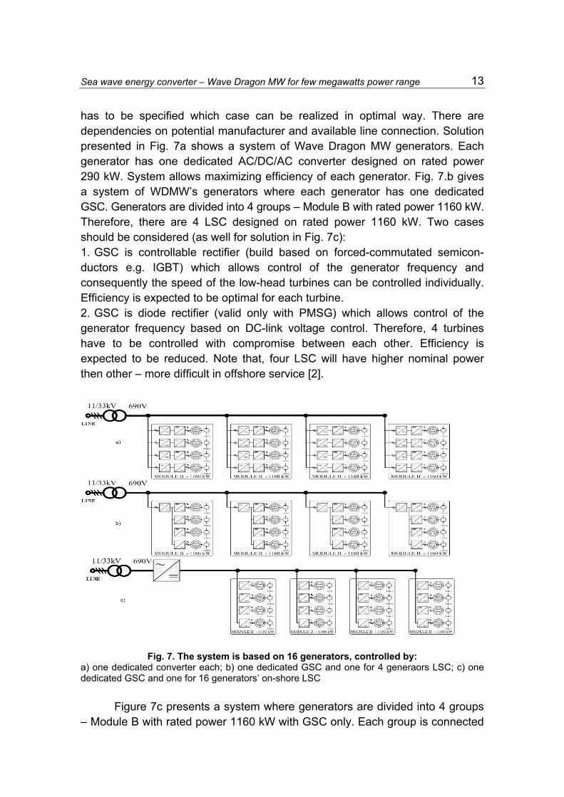
The target system in Wave Dragon MW is going to be build based on 16 generators. There are three cases for realization shown in Fig. 7.a, b, and c. It
Sea wave energy converter – Wave Dragon MW for few megawatts power range
13
has to be specified which case can be realized in optimal way. There are dependencies on potential manufacturer and available line connection. Solution presented in Fig. 7a shows a system of Wave Dragon MW generators. Each generator has one dedicated AC/DC/AC converter designed on rated power 290 kW. System allows maximizing efficiency of each generator. Fig. 7.b gives a system of WDMW’s generators where each generator has one dedicated GSC. Generators are divided into 4 groups – Module B with rated power 1160 kW. Therefore, there are 4 LSC designed on rated power 1160 kW. Two cases should be considered (as well for solution in Fig. 7c): 1. GSC is controllable rectifier (build based on forced-commutated semicon-ductors e.g. IGBT) which allows control of the generator frequency and consequently the speed of the low-head turbines can be controlled individually. Efficiency is expected to be optimal for each turbine. 2. GSC is diode rectifier (valid only with PMSG) which allows control of the generator frequency based on DC-link voltage control. Therefore, 4 turbines have to be controlled with compromise between each other. Efficiency is expected to be reduced. Note that, four LSC will have higher nominal power then other – more difficult in offshore service [2].
Fig. 7. The system is based on 16 generators, controlled by: a) one dedicated converter each; b) one dedicated GSC and one for 4 generaors LSC; c) one dedicated GSC and one for 16 generators’ on-shore LSC
Figure 7c presents a system where generators are divided into 4 groups – Module B with rated power 1160 kW with GSC only. Each group is connected

M. Kaźmierkowski, M. Jasiński, M. Malinowski, T. Płatek, S. Styński, ...
14
by common DC-link. Therefore, there are one LSC designed on rated power 4640kW. In this case LSC is expected to be located onshore. Therefore, there is possibility to use a DC cable to connect WDMW with a shore. System would operates like HVDC, therefore there is necessity taking into account three level LSC and GSC for optimal operation. 4. POWER ELECTRONICS SOLUTIONS - SIMULTIONS RESULTS Apart from other solution (depends on manufacturer) there are two main possibilities (Fig. 7): 1. AC/DC/AC converter – buck-to-buck converter (transistors based LSC and
GSC), 2. AC/DC/AC converter – transistor based LSC with step-up chopper (SUC) and
diode rectifier (DR) as a GSC. 5. CONCLUSIONS A prototype of the Wave Dragon has, as part of the preparations towards the full size multi MW Welsh production plant, been undergoing real sea testing in Nissum Bredning, Denmark. Planning for deployment of the 7 MW demonstration power plant in Wales is now well underway.
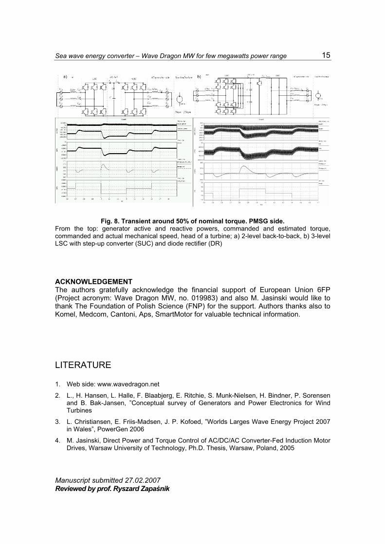
A full scale AC/DC/AC converter assures stable and robust condition in steady state as well as in transients [4]. In contrast to asynchronous Induction Generator (IG) which needs a gearbox, the Permanent Magnet Synchronous Generator (PMSG) doesn’t need a gearbox. Therefore, the system is expected to be more robust. Further, it should be pointed that synchronous machine can operate with power electronic converter consisted of transistor based LSC and DC step-up chopper with diode rectifier as GSC – in this case system would be simpler and cheaper, but torque pulsation in a machine will be significantly higher (Fig. 8b). However, all aspect should be considered and further investigations are required. Extended simulated and experimental results will be presented at the conference.
Sea wave energy converter – Wave Dragon MW for few megawatts power range
15
Fig. 8. Transient around 50% of nominal torque. PMSG side. From the top: generator active and reactive powers, commanded and estimated torque, commanded and actual mechanical speed, head of a turbine; a) 2-level back-to-back, b) 3-level LSC with step-up converter (SUC) and diode rectifier (DR) ACKNOWLEDGEMENT The authors gratefully acknowledge the financial support of European Union 6FP (Project acronym: Wave Dragon MW, no. 019983) and also M. Jasinski would like to thank The Foundation of Polish Science (FNP) for the support. Authors thanks also to Komel, Medcom, Cantoni, Aps, SmartMotor for valuable technical information. LITERATURE 1. Web side: www.wavedragon.net
2. L., H. Hansen, L. Halle, F. Blaabjerg, E. Ritchie, S. Munk-Nielsen, H. Bindner, P. Sorensen and B. Bak-Jansen, ”Conceptual survey of Generators and Power Electronics for Wind Turbines
3. L. Christiansen, E. Friis-Madsen, J. P. Kofoed, ”Worlds Larges Wave Energy Project 2007 in Wales”, PowerGen 2006
4. M. Jasinski, Direct Power and Torque Control of AC/DC/AC Converter-Fed Induction Motor Drives, Warsaw University of Technology, Ph.D. Thesis, Warsaw, Poland, 2005
Manuscript submitted 27.02.2007 Reviewed by prof. Ryszard Zapaśnik

M. Kaźmierkowski, M. Jasiński, M. Malinowski, T. Płatek, S. Styński, ...
16
PRZEKSZTAŁTNIK ENERGII FAL MORSKICH MW WAVE DRAGON NA POZIOMIE MOCY
W ZAKRESIE KILKU MEGA WATÓW
M. KAŹMIERKOWSKI, M. JASIŃSKI, M. MALINOWSKI, T. PŁATEK, S. STYŃSKI, P. ANTONIEWICZ,
W. KOŁOMYJSKI, D. ŚWIERCZYŃSKI, H. Ch. SOERENSEN, E. FRIIS-MADSEN,
L. CHRISTIANSEN, W. KNAPP, Z. ZHOU, P. IGIC
STRESZCZENIE: Artykuł ma na celu zebranie i przedsta-wienie podstawowych informacji na temat przekształtnika energii fal morskich Wave Dragon MW (WDMW). Ponadto również wstępne wyniki symulacyjne zespołu generator-przekształtnik energoelektro-niczny − sieć.