sealing solutions for nuclear feed water pumps - fsrugfsrug.org/presentations 2014/flowserve - mech...
TRANSCRIPT
High Performance Sealing Solutions for
Nuclear Feed Water Pumps
Presented by:Doug Reising
Flowserve Corporation Property and Confidential
Mechanical seals that require an extremely thin fluid film,
(seal face gap width < 15 µ-inch or 0.38 µm), to control seal
leakage combined with high reliability on operating conditions,
which are significantly tougher and demanding than the average
bulk of sealing applications
A normal seal operates on a feed water application of 1.5 MPa at 3600 RPM, on an average seal loop temperature of 140 F (60 C)
A high performance mechanical seal operates on a feed water application of 3.5 MPa at 6000 RPM, on an average seal loop temperature of 140 F (60 C)
Definition High Performance Mechanical Seal:
2
Flowserve Corporation Property and Confidential
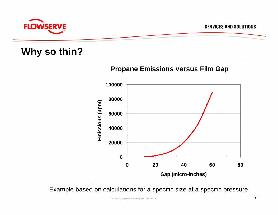
Why so thin?Propane Emissions versus Film Gap
0
20000
40000
60000
80000
100000
0 20 40 60 80
Gap (micro-inches)
Emis
sion
s (p
pm)
Example based on calculations for a specific size at a specific pressure3
Flowserve Corporation Property and Confidential
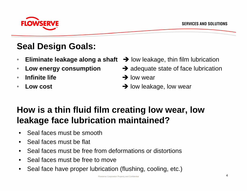
How is a thin fluid film creating low wear, low leakage face lubrication maintained?• Seal faces must be smooth• Seal faces must be flat• Seal faces must be free from deformations or distortions• Seal faces must be free to move• Seal face have proper lubrication (flushing, cooling, etc.)
Seal Design Goals:• Eliminate leakage along a shaft low leakage, thin film lubrication• Low energy consumption adequate state of face lubrication• Infinite life low wear• Low cost low leakage, low wear
4
Flowserve Corporation Property and Confidential
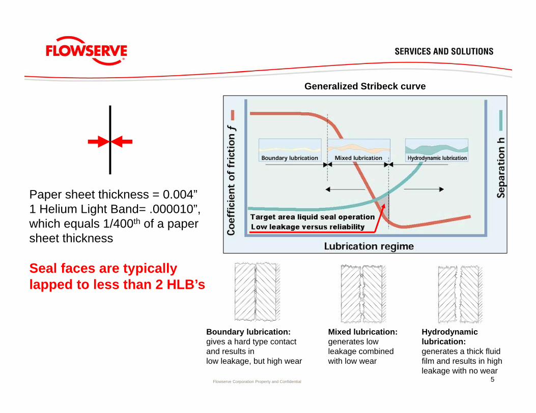
Generalized Stribeck curve
Mixed lubrication:generates low leakage combined with low wear
Hydrodynamic lubrication:generates a thick fluid film and results in high leakage with no wear
Boundary lubrication:gives a hard type contact and results inlow leakage, but high wear
Paper sheet thickness = 0.004”1 Helium Light Band= .000010”,which equals 1/400th of a paper sheet thickness
Seal faces are typically lapped to less than 2 HLB’s
5

Flowserve Corporation Property and Confidential
Low seal leakage:
• High seal balance ratio • Thin film: light contact• Minimal radial face taper
(flat running seal faces)• Minimal waviness
(distortions by drive pins, face geometry, etc.)
• Leakage approximately proportional to the cube of the gap
Low seal face wear:
• Low seal balance ratio (light loading)
• Flat or convergent face taper• Moderate roughness
(lubricity)• Lubrication enhancements
(grooves, waves)• Good quality materials• Good sealing environment
(flush, cooling, cleanliness)
6
Flowserve Corporation Property and Confidential
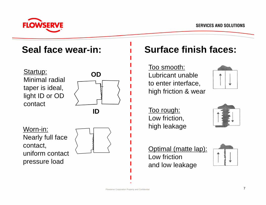
Too smooth:Lubricant unableto enter interface,high friction & wear
Too rough:Low friction,high leakage
Optimal (matte lap):Low frictionand low leakage
Surface finish faces:Seal face wear-in:
OD
ID
Startup:Minimal radial taper is ideal, light ID or OD contact
Worn-in:Nearly full face contact,uniform contact pressure load
7
Flowserve Corporation Property and Confidential
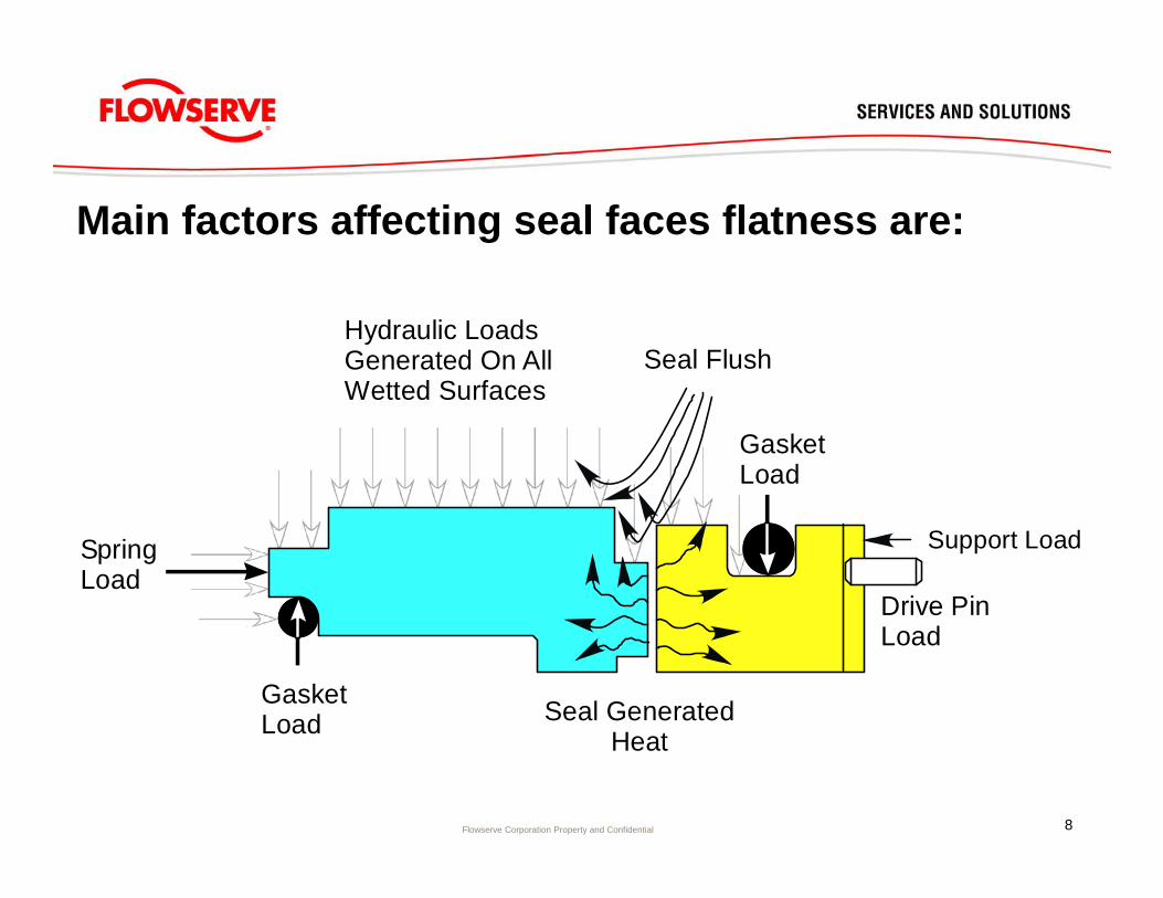
Main factors affecting seal faces flatness are:
SpringLoad
GasketLoad
GasketLoad
Drive PinLoad
Seal GeneratedHeat
Seal FlushHydraulic LoadsGenerated On AllWetted Surfaces
Support Load
8
Flowserve Corporation Property and Confidential
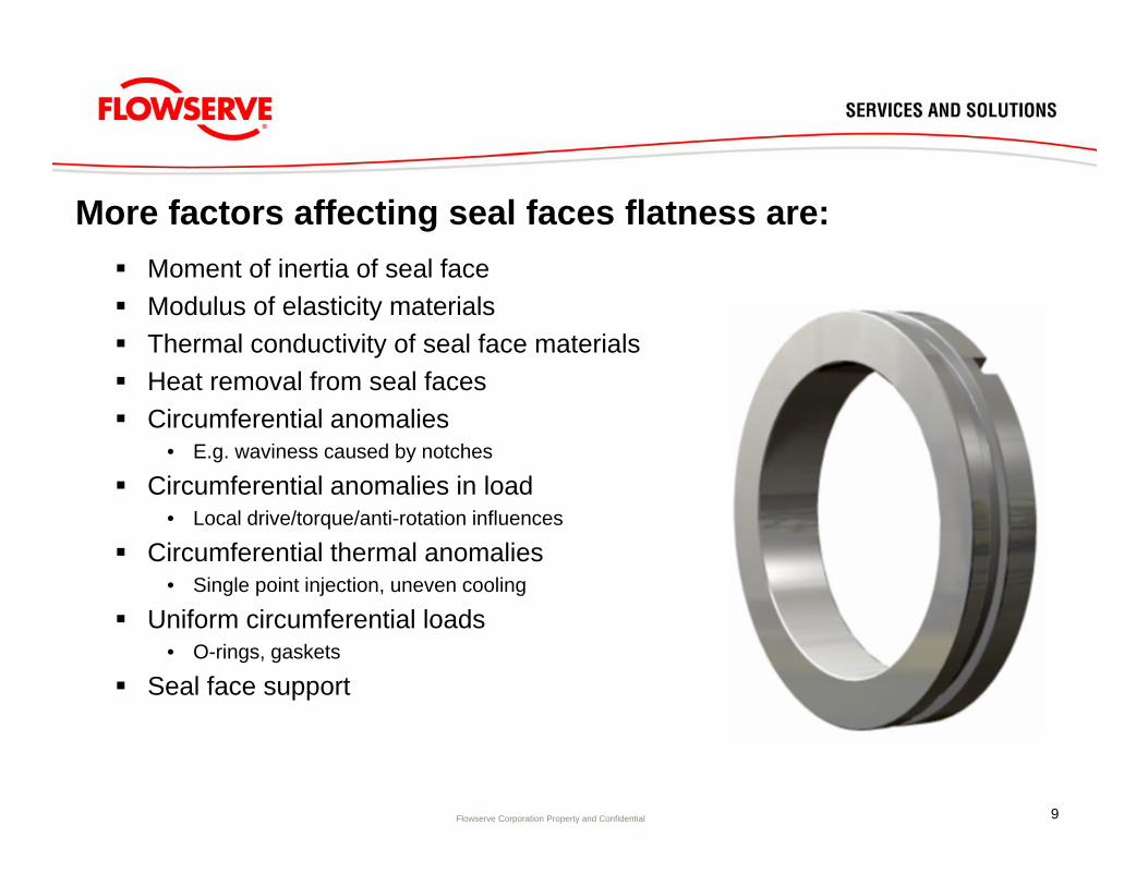
Moment of inertia of seal face Modulus of elasticity materials Thermal conductivity of seal face materials Heat removal from seal faces Circumferential anomalies
• E.g. waviness caused by notches
Circumferential anomalies in load• Local drive/torque/anti-rotation influences
Circumferential thermal anomalies• Single point injection, uneven cooling
Uniform circumferential loads• O-rings, gaskets
Seal face support
More factors affecting seal faces flatness are:
9

Flowserve Corporation Property and Confidential
Factors that affect pressure distortion of a seal face: Modulus of elasticity of material Moment of inertia around centroid Differential pressure Relationship of resultant load to centroid and support surfaces/constraints Shape of face (especially for local deformations)
Simple ring Seal face geometry
10
Flowserve Corporation Property and Confidential
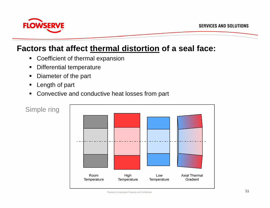
Factors that affect thermal distortion of a seal face: Coefficient of thermal expansion Differential temperature Diameter of the part Length of part Convective and conductive heat losses from part
Simple ring
11
Flowserve Corporation Property and Confidential
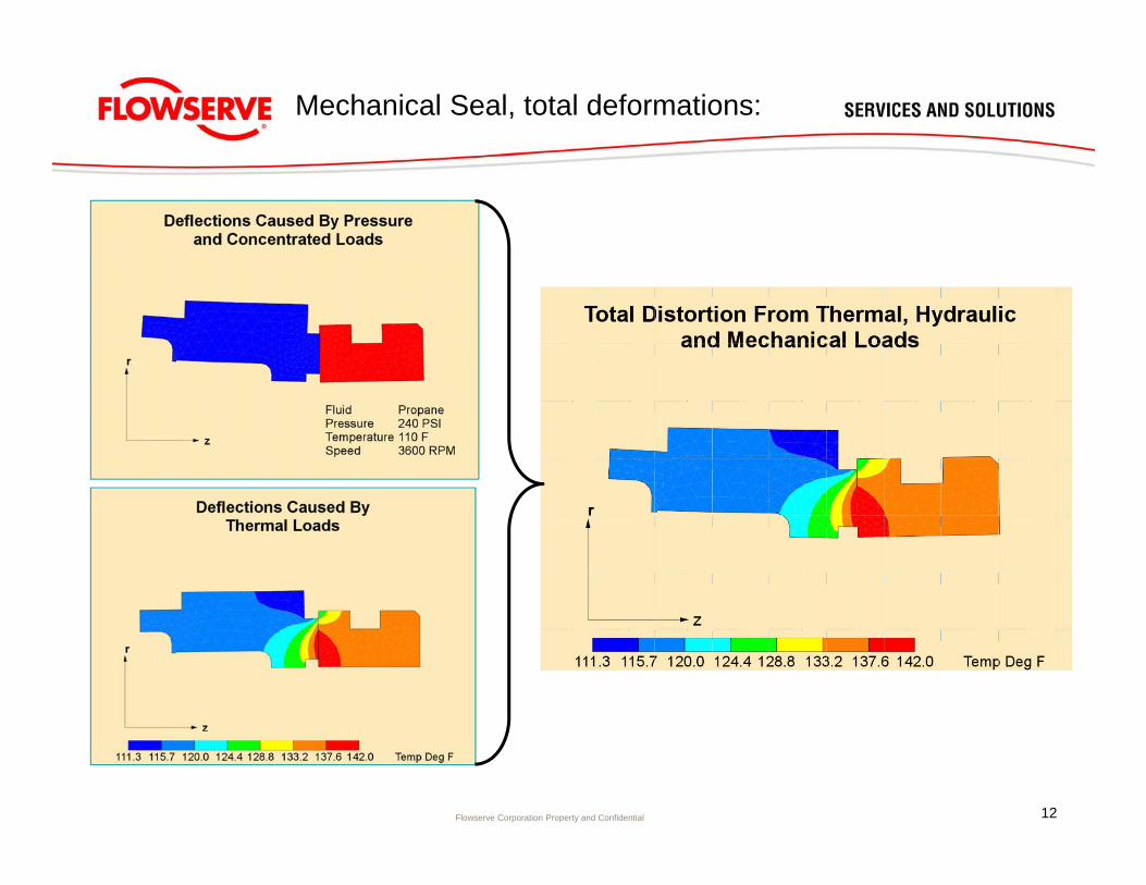
Mechanical Seal, total deformations:
12
Flowserve Corporation Property and Confidential
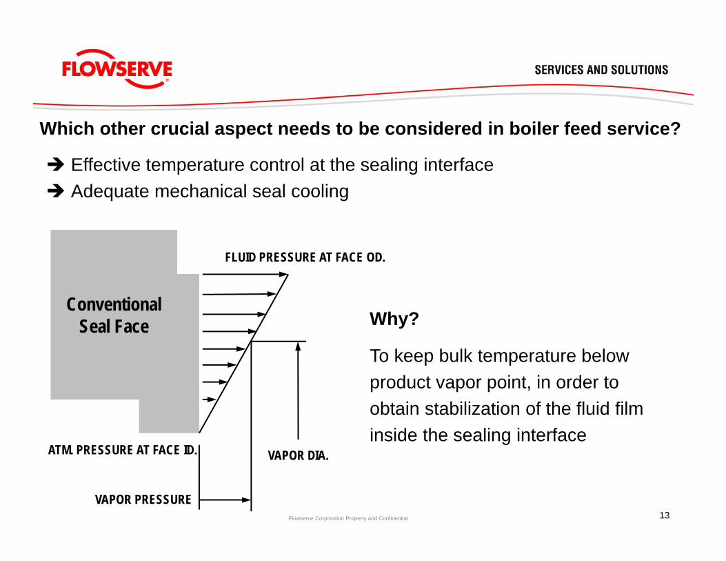
Why?
To keep bulk temperature below product vapor point, in order to obtain stabilization of the fluid film inside the sealing interface
ConventionalSeal Face
VAPOR PRESSURE
VAPOR DIA.
FLUID PRESSURE AT FACE OD.
ATM. PRESSURE AT FACE ID.
Which other crucial aspect needs to be considered in boiler feed service?
Effective temperature control at the sealing interface Adequate mechanical seal cooling
13
Flowserve Corporation Property and Confidential
How?Insulate the mechanical seal area from the hot pump influences by:1. Apply additional seal chamber cooling, either through using the existing cover jacket or by
using a seal flange integrated cooling jacket design2. Make the exchange of hot pump liquid with relatively cold seal plan 23 seal liquid, as
difficult as possible. Apply physical barriers, if needed!3. Only use seal plan 23 as piping arrangement for such boiler feed pump seals4. Use a multi point injection to ensure an evenly divided temperature distribution around the
circumference of the sealing interface5. Inject the cooled seal plan 23 fluid directly at the sealing interface (if possible)6. Use a thermal breaks (air gaps) between pump cover and seal gland7. Make sure that the external seal plan 23 seal coolers selected, are up to the job and
installed correctly. Full product and coolant side venting is mandatory. Positioning of coolers is crucial in relation to thermo-siphoning needed during hot stand-by
8. Always use magnetic separators in the loop, to filter out hematite, magnetite or any other magnetic particles present in the pump fluid
9. Make sure interconnecting piping is executed correctly and can be vented completely. (Preference is for sloped upwards piping from seal to seal cooler and sloped downward piping from seal cooler back to seal)
14
Flowserve Corporation Property and Confidential
Why seal plan 23?
• The simplest and most efficient way of maintaining the seal operating temperature below 140 F, is to use a seal plan 23 cooling loop.
• If correctly sized, installed and commissioned, seal loop operating temperatures can be as low as 104 F on a main feed pump operating at 7000 RPM with product temperatures > 480 F !
CRUCIAL ASPECT TO CONSIDER WHEN APPLYING SEAL PLAN 23:The heat exchanger requires mounting ± 16 – 24 inch above the pump centerline!
This location is critical to the promote thermo-siphon when the pump is placed on “hot-standby” – thereby effectively preventing the seal from “overheating” (i.e. elastomer damage and thermal deformation of seal faces)
Thermal shock of the ceramic seal faces may occur at pump start-up, if proper thermo-siphoning is not taking place
15

Flowserve Corporation Property and Confidential
DHTW - 6000 feed pump seal for Electrabel Tihange 2 - 3 (PWR), Belgium
DHTW - 6500 feed pump seal for Forsmark III (BWR), Sweden
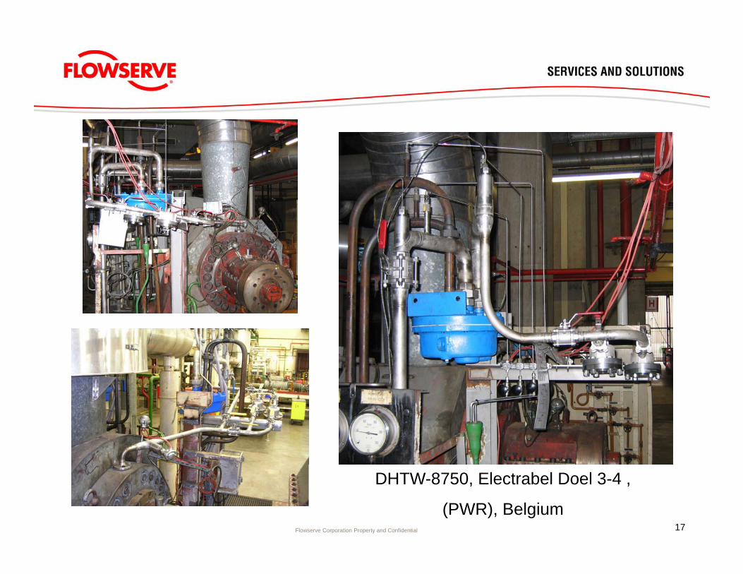
DHTW - 8750 feed pump seals for Electrabel Doel 3 - 4 (PWR), Belgium
DHTW - 7750 feed pump seal for CN Almaraz I - II (PWR), Spain
Recent seal upgrade projects:
16
Flowserve Corporation Property and Confidential 17
DHTW-8750, Electrabel Doel 3-4 ,
(PWR), Belgium
Flowserve Corporation Property and Confidential
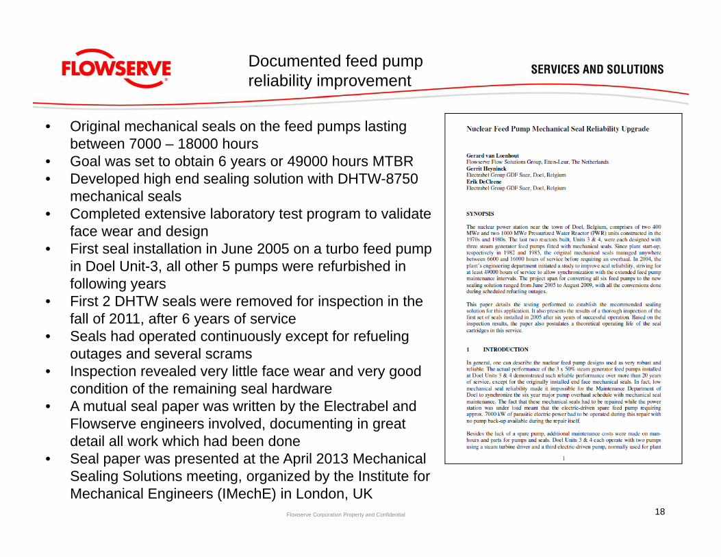
• Original mechanical seals on the feed pumps lasting between 7000 – 18000 hours
• Goal was set to obtain 6 years or 49000 hours MTBR• Developed high end sealing solution with DHTW-8750
mechanical seals• Completed extensive laboratory test program to validate
face wear and design• First seal installation in June 2005 on a turbo feed pump
in Doel Unit-3, all other 5 pumps were refurbished in following years
• First 2 DHTW seals were removed for inspection in the fall of 2011, after 6 years of service
• Seals had operated continuously except for refueling outages and several scrams
• Inspection revealed very little face wear and very good condition of the remaining seal hardware
• A mutual seal paper was written by the Electrabel and Flowserve engineers involved, documenting in great detail all work which had been done
• Seal paper was presented at the April 2013 Mechanical Sealing Solutions meeting, organized by the Institute for Mechanical Engineers (IMechE) in London, UK
18
Documented feed pump reliability improvement
Flowserve Corporation Property and Confidential
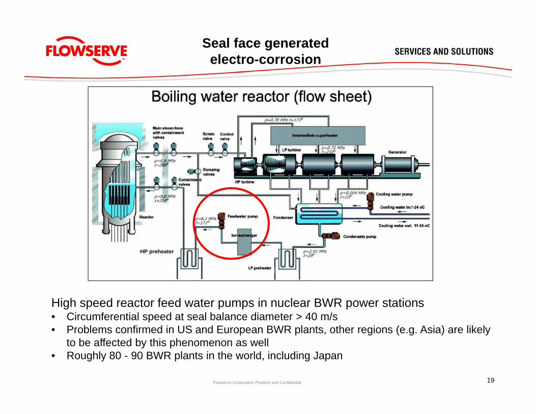
Seal face generated electro-corrosion
HP preheater
High speed reactor feed water pumps in nuclear BWR power stations• Circumferential speed at seal balance diameter > 40 m/s• Problems confirmed in US and European BWR plants, other regions (e.g. Asia) are likely
to be affected by this phenomenon as well• Roughly 80 - 90 BWR plants in the world, including Japan
19
Flowserve Corporation Property and Confidential
Conclusions Flowserve R&D and engineering project (2003 – 2013):
1. Seal face generated electro corrosion development is closely related to:• Electrical conductivity of the water sealed• Circumferential speed of the mechanical seal • Applied seal face materials and their combinations
2. Limited variation in the seal water temperature or sealing pressure do not seem to be major factors in development of this phenomenon
3. Seal face generated electro corrosion seems to be created very locally inside the sealing interface, whereby external solutions, such as a grounding wire are not very effective in solving or minimizing the problem
4. Use of seal face friction reduction features involving precision face topography and preferential surface treatment present a partial solution to this problem
5. The most crucial part of the solution development is to apply a rotating seal face material, which possesses an equally high electrical conductivity (or low resistivity) than its opposing carbon graphite stationary seal face
Seal face generated electro-corrosion
20
Flowserve Corporation Property and Confidential
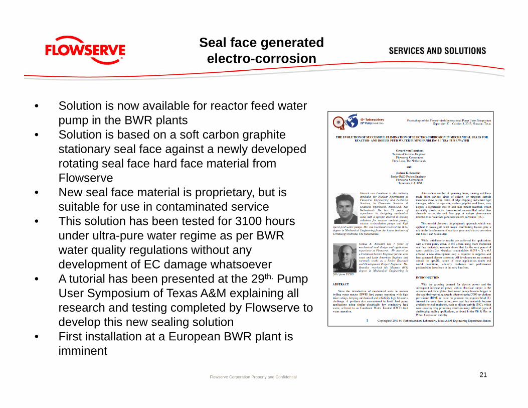
• Solution is now available for reactor feed water pump in the BWR plants
• Solution is based on a soft carbon graphite stationary seal face against a newly developed rotating seal face hard face material from Flowserve
• New seal face material is proprietary, but is suitable for use in contaminated service
• This solution has been tested for 3100 hours under ultra-pure water regime as per BWR water quality regulations without any development of EC damage whatsoever
• A tutorial has been presented at the 29th. Pump User Symposium of Texas A&M explaining all research and testing completed by Flowserve to develop this new sealing solution
• First installation at a European BWR plant is imminent
Seal face generated electro-corrosion
21
22