sealing technologies for the oil&gas industry
TRANSCRIPT
SEALING TECHNOLOGIES
FOR THE OIL&GAS INDUSTRY

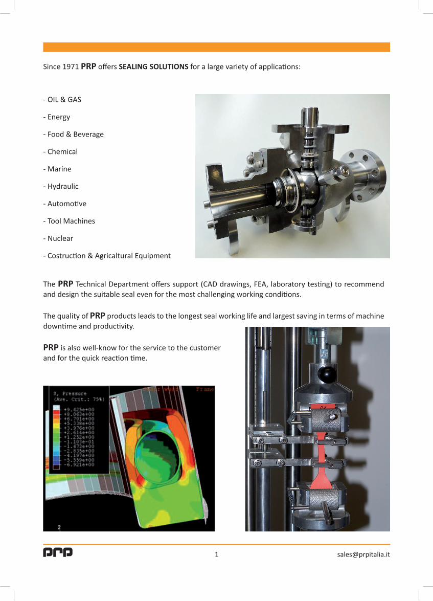
Since 1971 PRP offers SEALING SOLUTIONS for a large variety of applications:
- OIL & GAS
- Energy
- Food & Beverage
- Chemical
- Marine
- Hydraulic
- Automotive
- Tool Machines
- Nuclear
- Costruction & Agricaltural Equipment
The PRP Technical Department offers support (CAD drawings, FEA, laboratory testing) to recommend and design the suitable seal even for the most challenging working conditions.
The quality of PRP products leads to the longest seal working life and largest saving in terms of machine downtime and productivity.
PRP is also well-know for the service to the customer and for the quick reaction time.

2
Several years ago PRP started developing the αSEAL product range to satisfy the demanding requirements of customers active in the OIL & GAS business, in particular producers of Trunnion Mounted Ball Valves.
The harsh working conditions, the increasing pressure levels and the request of certified material made PRP the leading provider of sealing solutions for Sub Sea and Top Side valves as per ANSI, API 6A, and API 6D standards.
The αSEAL LIPRING is available with a variety of profiles and components to withstand high sour gas (H2S) concentrations.
BALL VALVES - GATE VALVES - VALVE ACTUATORS
- αSEAL LIPRING for Valve SPE and DPE Seats.
- αSEAL LIPRING and V-PACK for Stem seals (Low Fugitive Emissions).
- αSEAL LIPRING for Body and Cover seals.
- αSEAL C-Rings.
- αSEAL O-Ring in different elastomeric compounds.
- αSEAL Graphite Packing for Valve Seat and Stem.
- αSEAL Thermosetting Guide Rings for Actuators.
ANY SEAL SIZE
FROM CRYOGENIC (-196°C) TO VERY HIGH TEMPERATURE
PRESSURE UP TO 15000 psi
NORSOK M710 AND M630 APPROVED MATERIALS
NACE MR-01-75 SPRINGS
ANTI-EXPLOSIVE DECOMPRESSION O-RINGS
LOW TEMPERATURE O-RINGS
ALPHASEAL for OIL&GAS
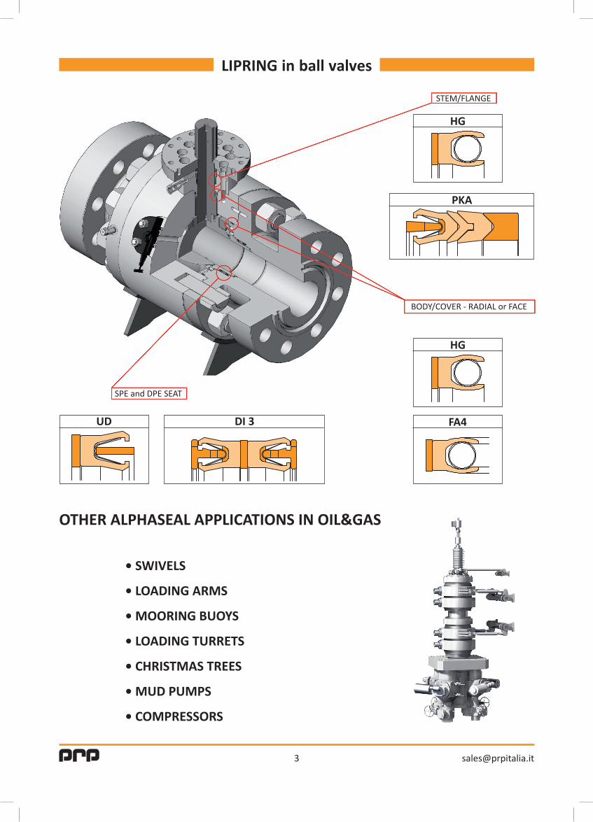
BODY/COVER - RADIAL or FACE
SPE and DPE SEAT
STEM/FLANGE
3
LIPRING in ball valves
OTHER ALPHASEAL APPLICATIONS IN OIL&GAS
•SWIVELS
•LOADINGARMS
•MOORINGBUOYS
•LOADINGTURRETS
•CHRISTMASTREES
•MUDPUMPS
•COMPRESSORS
HG
HG
FA4DI 3UD
PKA

The LIPRING consists of a polymeric jacket which is energized by a metallic spring when installed into a groove. It offers many of the well-known advantages of the common elastomeric O-rings while avoiding many of its limitations. The resilient spring element responds with constant force, pushing out the sealing lips, creating a tight seal against the groove mating surfaces. The open end of the jacket is orientated towards the highest pressure side and allows the hydrostatic pressure to energize the seal and supplement the spring force which increases contact pressure and eliminates potential leakage.The use of a resilient spring element ensures positive sealing even at low-pressure and compensates for jacket wall reduction from cold flow, wear and thermal contraction. In conditions that see thermal cycling, the spring system continues to energize the seal lips without taking a compression set or becoming too soft or hard. Many different spring designs are available in corrosion resistant metal alloys including stainless steel, cobalt chromium - nickel alloy, Inconel® and Hastelloy®. Jacket profiles are typically made from PTFE based and other high-performance polymer plastics, often with special additives to enhance, for example, wear resistance or high-temperature strenght. PTFE offers excellent inherent low friction characteristics and an outstanding high degree of chemical inertness. Additionally, polymers are less prone to some of the problems associated with elastomeric seals including explosive decompression and stick-slip. LIPRINGS are precision lathe-turned parts. Although PRP offers selected sizes to fit many popular international O-ring cavities, the fact is that the LIPRING system can be tailored to any existing customer groove geometry.
SelectingtheLIPRINGsizeforyourapplicationStandard LIPRINGS are available in any diameter from 2.5 mm up to 3000 mm and a variety of cross-sections to fit the various groove sizes you may have.Please refer to the page of the LIPRING type selected for your application to determine the appropriate diameter, cross-section and housing dimensions.
Jacket materialPRP draws on hundreds of PTFE compounds and other polymeric materials to manufacture the LIPRING jacket profile. Our material range includes unfilled PTFE, standard and speciality filled PTFE compounds, TFM blends, UHMW polyethylene, thermoplastics, PEEK, polymide, ecc.PRP can meet your material requirements for polymer sealing in most environmental and operating conditions.You can find the most common compounds in the following list. For other compounds please contact our Technical Department.
4
What is a LIPRING and how does it work
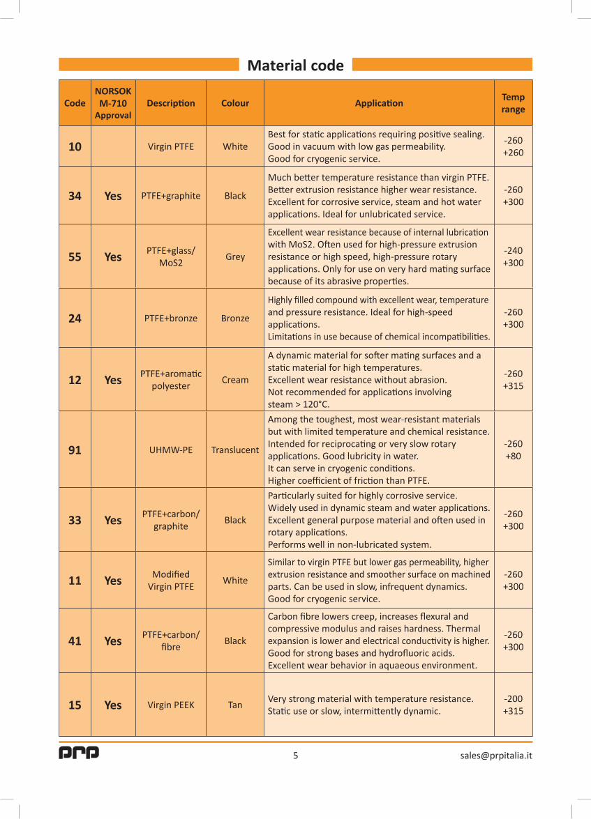
CodeNORSOKM-710
ApprovalDescription Colour Application
Temprange
10 Virgin PTFE WhiteBest for static applications requiring positive sealing.Good in vacuum with low gas permeability.Good for cryogenic service.
-260+260
34 Yes PTFE+graphite Black
Much better temperature resistance than virgin PTFE.Better extrusion resistance higher wear resistance.Excellent for corrosive service, steam and hot waterapplications. Ideal for unlubricated service.
-260+300
55 Yes PTFE+glass/MoS2
Grey
Excellent wear resistance because of internal lubricationwith MoS2. Often used for high-pressure extrusionresistance or high speed, high-pressure rotaryapplications. Only for use on very hard mating surfacebecause of its abrasive properties.
-240+300
24 PTFE+bronze Bronze
Highly filled compound with excellent wear, temperatureand pressure resistance. Ideal for high-speedapplications.Limitations in use because of chemical incompatibilities.
-260+300
12 Yes PTFE+aromaticpolyester
Cream
A dynamic material for softer mating surfaces and astatic material for high temperatures.Excellent wear resistance without abrasion.Not recommended for applications involvingsteam > 120°C.
-260+315
91 UHMW-PE Translucent
Among the toughest, most wear-resistant materialsbut with limited temperature and chemical resistance.Intended for reciprocating or very slow rotaryapplications. Good lubricity in water. It can serve in cryogenic conditions.Higher coefficient of friction than PTFE.
-260+80
33 Yes PTFE+carbon/graphite
Black
Particularly suited for highly corrosive service.Widely used in dynamic steam and water applications.Excellent general purpose material and often used inrotary applications.Performs well in non-lubricated system.
-260+300
11 Yes ModifiedVirgin PTFE
White
Similar to virgin PTFE but lower gas permeability, higherextrusion resistance and smoother surface on machinedparts. Can be used in slow, infrequent dynamics.Good for cryogenic service.
-260+300
41 Yes PTFE+carbon/fibre
Black
Carbon fibre lowers creep, increases flexural andcompressive modulus and raises hardness. Thermalexpansion is lower and electrical conductivity is higher.Good for strong bases and hydrofluoric acids.Excellent wear behavior in aquaeous environment.
-260+300
15 Yes Virgin PEEK TanVery strong material with temperature resistance.Static use or slow, intermittently dynamic.
-200+315
5
Material code
6
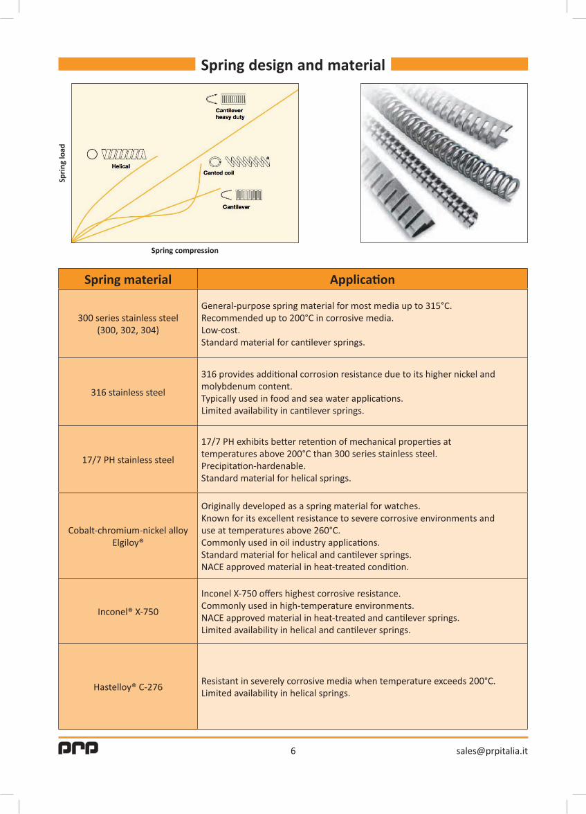
Spring design and materialSp
ring
load
Spring compression
Spring material Application
300 series stainless steel(300, 302, 304)
General-purpose spring material for most media up to 315°C.Recommended up to 200°C in corrosive media.Low-cost.Standard material for cantilever springs.
316 stainless steel
316 provides additional corrosion resistance due to its higher nickel andmolybdenum content.Typically used in food and sea water applications.Limited availability in cantilever springs.
17/7 PH stainless steel
17/7 PH exhibits better retention of mechanical properties attemperatures above 200°C than 300 series stainless steel.Precipitation-hardenable.Standard material for helical springs.
Cobalt-chromium-nickel alloyElgiloy®
Originally developed as a spring material for watches.Known for its excellent resistance to severe corrosive environments anduse at temperatures above 260°C.Commonly used in oil industry applications.Standard material for helical and cantilever springs.NACE approved material in heat-treated condition.
Inconel® X-750
Inconel X-750 offers highest corrosive resistance.Commonly used in high-temperature environments.NACE approved material in heat-treated and cantilever springs.Limited availability in helical and cantilever springs.
Hastelloy® C-276Resistant in severely corrosive media when temperature exceeds 200°C.Limited availability in helical springs.
7
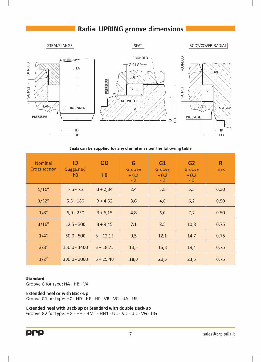
Radial LIPRING groove dimensions
NominalCross section
IDSuggested
h8
OD
H8
GGroove
+ 0,2- 0
G1Groove
+ 0,2- 0
G2Groove
+ 0,2- 0
Rmax
1/16” 7,5 - 75 B + 2,84 2,4 3,8 5,3 0,30
3/32” 5,5 - 180 B + 4,52 3,6 4,6 6,2 0,50
1/8” 6,0 - 250 B + 6,15 4,8 6,0 7,7 0,50
3/16” 12,5 - 300 B + 9,45 7,1 8,5 10,8 0,75
1/4” 50,0 - 500 B + 12,12 9,5 12,1 14,7 0,75
3/8” 150,0 - 1400 B + 18,75 13,3 15,8 19,4 0,75
1/2” 300,0 - 3000 B + 25,40 18,0 20,5 23,5 0,75
Sealscanbesuppliedforanydiameterasperthefollowingtable
StandardGroove G for type: HA - HB - VA
Extended heel or with Back-upGroove G1 for type: HC - HD - HE - HF - VB - VC - UA - UB
Extended heel with Back-up or Standard with double Back-upGroove G2 for type: HG - HH - HM1 - HN1 - UC - VD - UD - VG - UG
STEM/FLANGE SEAT BODY/COVER-RADIAL

8
Face LIPRING groove dimensions - internal pressure
NominalCross section
ODSuggested
H11
DGroove
depth range
GGroove
width min.
G1Groove
width min.
G2Groove
width min.
Rmax
1/16” 10 - 65 1,42 - 1,47 2,4 3,3 5,3 0,30
3/32” 14 - 100 2,26 - 2,31 3,6 4,5 6,2 0,50
1/8” 25 - 200 3,07 - 3,12 4,8 6,5 7,7 0,50
3/16” 48 - 350 4,62 - 4,68 7,1 8,0 10,8 0,75
1/4” 115 - 400 6,05 - 6,12 9,5 11,3 14,7 0,75
3/8” 200 - 1000 9,47 - 9,58 13,3 15,8 19,4 0,75
1/2” 325 - 3000 12,70 - 12,80 18,0 20,5 23,5 0,75
Sealscanbesuppliedforanydiameterasperthefollowingtable
StandardGroove G for type: FA1 - FE1
Extended heel or with Back-upGroove G1 for type: FA2 - FA3 - FE2 - FE3
Extended heel with Back-up or Standard with double Back-upGroove G2 for type: FA4 - FA6 - FE4 - FE6

9
Face LIPRING groove dimensions - external pressure
NominalCross section
ODSuggested
H11
DGroove
depth range
GGroove
width min.
G1Groove
width min.
G2Groove
width min.
Rmax
1/16” 5 - 65 1,42 - 1,47 2,4 3,3 5,3 0,30
3/32” 10 - 100 2,26 - 2,31 3,6 4,5 6,2 0,50
1/8” 20 - 200 3,07 - 3,12 4,8 6,5 7,7 0,50
3/16” 40 - 350 4,62 - 4,68 7,1 8,0 10,8 0,75
1/4” 90 - 400 6,05 - 6,12 9,5 11,3 14,7 0,75
3/8” 200 - 1000 9,47 - 9,58 13,3 15,8 19,4 0,75
1/2” 300 - 3000 12,70 - 12,80 18,0 20,5 23,5 0,75
Sealscanbesuppliedforanydiameterasperthefollowingtable
StandardGroove G for type: FC1 - FG1
Extended heel or with Back-upGroove G1 for type: FC2 - FC3 - FG2 - FG3
Extended heel with Back-up or Standard with double Back-upGroove G2 for type: FC4 - FC6 - FG4 - FG6
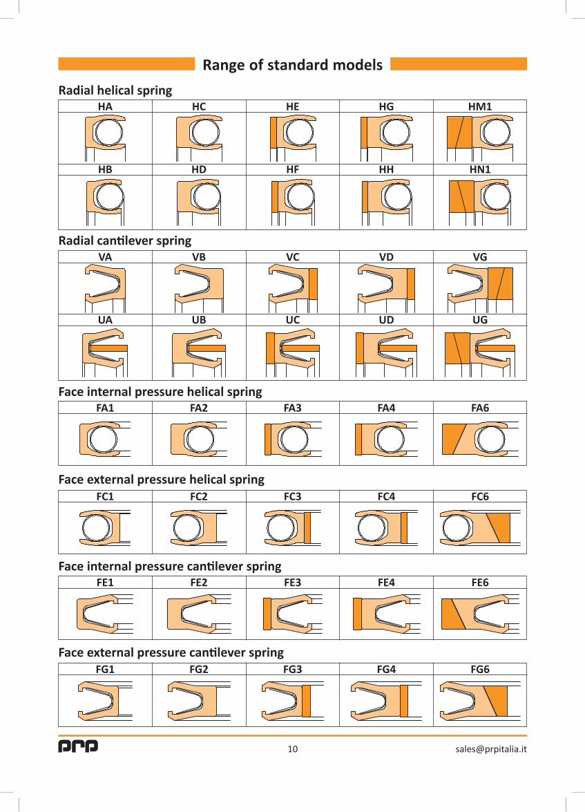
Range of standard models
Radial helical spring
Radialcantileverspring
Face internal pressure helical spring
Face external pressure helical spring
Faceinternalpressurecantileverspring
Faceexternalpressurecantileverspring
HA
VA
FA1
FC1
FE1
FG1
HC
VB
FA2
FC2
FE2
FG2
HE
VC
FA3
FC3
FE3
FG3
HG
VD
FA4
FC4
FE4
FG4
HM1
VG
FA6
FC6
FE6
FG6
HB
UA
HD
UB
HF
UC
HH
UD
HN1
UG
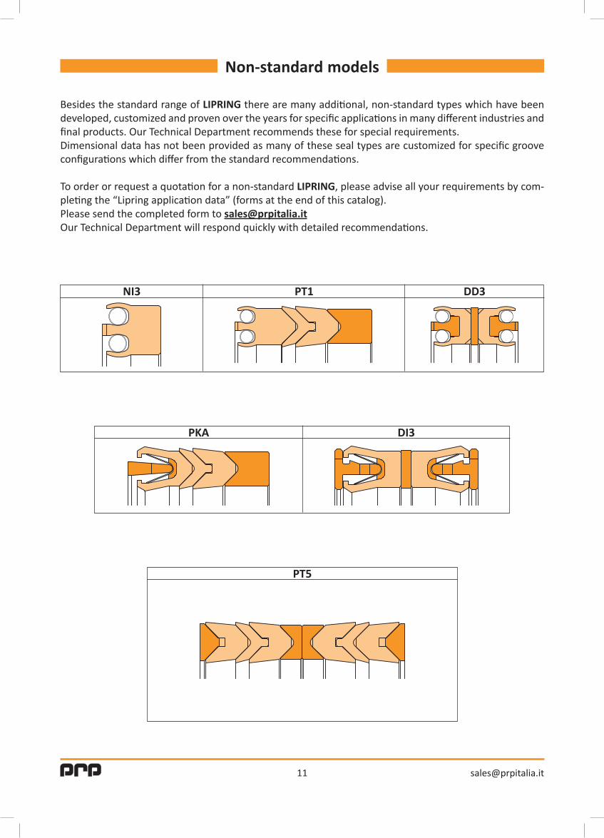
Non-standard models
PT5
NI3 PT1 DD3
PKA DI3
Besides the standard range of LIPRING there are many additional, non-standard types which have been developed, customized and proven over the years for specific applications in many different industries and final products. Our Technical Department recommends these for special requirements.Dimensional data has not been provided as many of these seal types are customized for specific groove configurations which differ from the standard recommendations.
To order or request a quotation for a non-standard LIPRING, please advise all your requirements by com-pleting the “Lipring application data” (forms at the end of this catalog).Please send the completed form to [email protected] Technical Department will respond quickly with detailed recommendations.
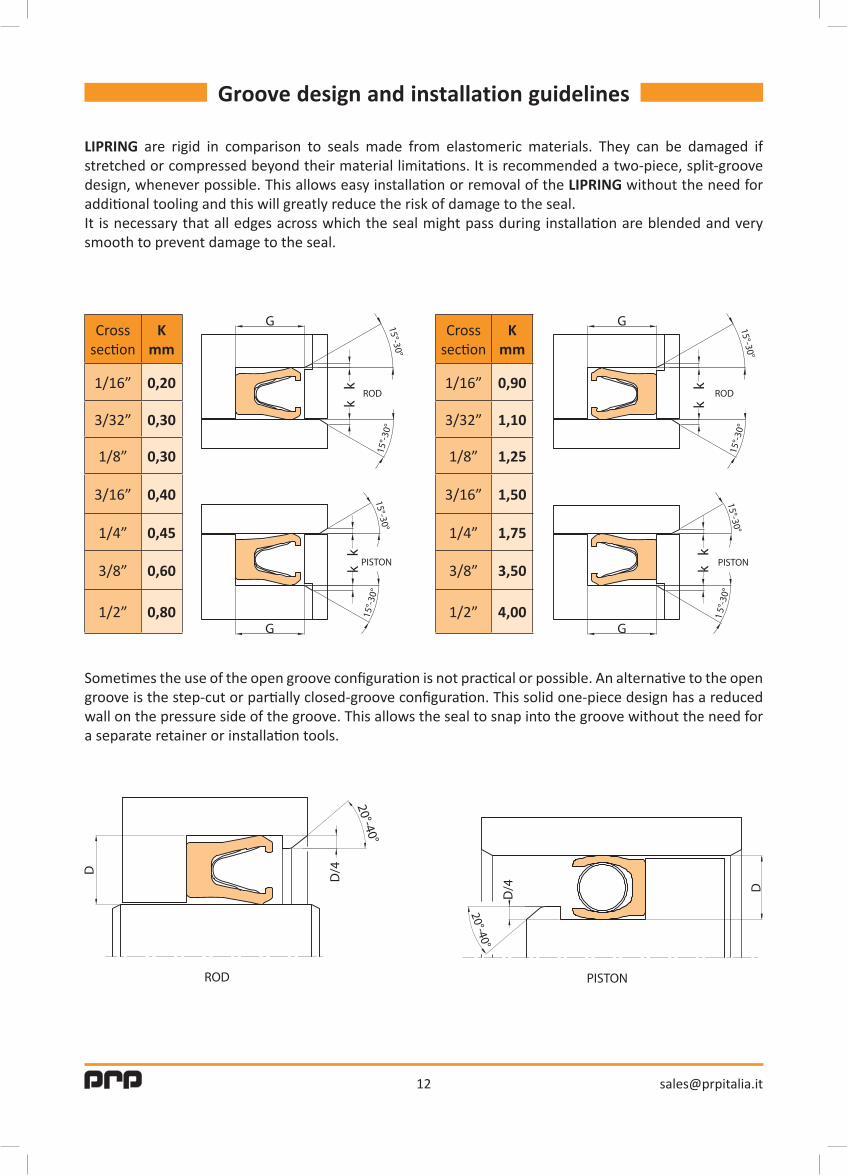
Groove design and installation guidelines
LIPRING are rigid in comparison to seals made from elastomeric materials. They can be damaged if stretched or compressed beyond their material limitations. It is recommended a two-piece, split-groove design, whenever possible. This allows easy installation or removal of the LIPRING without the need for additional tooling and this will greatly reduce the risk of damage to the seal.It is necessary that all edges across which the seal might pass during installation are blended and very smooth to prevent damage to the seal.
Sometimes the use of the open groove configuration is not practical or possible. An alternative to the open groove is the step-cut or partially closed-groove configuration. This solid one-piece design has a reduced wall on the pressure side of the groove. This allows the seal to snap into the groove without the need for a separate retainer or installation tools.
Crosssection
Kmm
1/16” 0,20
3/32” 0,30
1/8” 0,30
3/16” 0,40
1/4” 0,45
3/8” 0,60
1/2” 0,80
Crosssection
Kmm
1/16” 0,90
3/32” 1,10
1/8” 1,25
3/16” 1,50
1/4” 1,75
3/8” 3,50
1/2” 4,00

SealType Materials Class A Class B Class C Class DVirgin PTFE (10), TFM (11)
PTFE graphite (34) PTFE aromatic polyester (12)
0.10 0.08 0.05 ----
PTFE GlassMoS2 (55)PTFE Bronze (24)
UHMWPE (91) PTFE Carbon Graphite (33)
PTFE Carbon fiber (41)
0.15 0.1 0.08 0.05
Virgin PTFE (10), TFM (11) PTFE graphite (34)
PTFE aromatic polyester (12)0.20 0.10 0.08 ----
PTFE GlassMoS2 (55) PTFE Bronze (24) UHMWPE (91)
PTFE Carbon Graphite (33) PTFE Carbon fiber (41)
0.25 0.20 0.10 0.08
PTFE GlassMoS2 (55) PTFE Bronze (24) UHMWPE (91)
PTFE Carbon Graphite (33) PTFE Carbon fiber (41)
0.25 0.20 0.10 0.08
PEEK (15) 0.30 0.25 0.20 0.10
Temperature, pressure and extrusion gap
Maximum extrusion gap (mm)
The pressure capability of a LIPRING is a function of temperature, pressure, seal material, seal design, and extrusion gap. An excessive extrusion gap in the given application conditions will cause the polymer material to migrate towards the clearance until rupture in the jacket material and failure of the seal are inevitable. Eccentricity also affects the extrusion gap and should be considered in the seal design.
In case of a combination of pressure and temperature above Class D or in case of an operating temperature above 260 °C, pls. consult our Technical Department. Hardware designs without centering devices must consider the diametral clearance as the maximum extrusion gap.

Surface finish and hardness
Proper surface finish of the seal groove is critical to ensure positive sealing and achieve the longest possible seal life in dynamic applications.Mating surfaces that are too rough can create leak paths and be very abrasive to the seal.To maximize seal performance, the recommendations for surface roughness in table below.
As a general rule, the higher the sealing surface hardness the better the seal performance.Higher hardness reduces wear and increases seal life.
Fluid Static Dynamic Rotation
Gas/ Low temperatureHydrogen
HeliumFreon
OxygenLiquid nitrogen
Ra=0,3µm Ra=0,2µm Ra=0,1µm
Low viscosity gases/liquidsAir
AlcoholGaseous Nitrogen
Natural gas
Ra=0,6µm Ra=0,3µm Ra=0,2µm
Medium and high viscosity fluids Water
Oil Grease
Liquid adhesives
Ra=0,8µm Ra=0,4µm Ra=0,2µm

LIPRING APPLICATION DATA 1
Company
Internal diameter with tolerance (ID)
External diameter with tolerance (OD)
Groove length (G)
Extrusion gap (E) / (E1)
Media / Service
Operating temperature
Operating pressure
Test Pressure
Stem chamfer (L1)x(α°1)
Flange chamfer (L2)x(α°2)
Radius (R)
Roughness (Ra)
Special request
Others
Phone
Reference person E-mail
Liquid Gas
STEM/FLANGE

LIPRING APPLICATION DATA 2
Company
Internal diameter with tolerance (ID)
External diameter with tolerance (OD)
Groove length (G)
Extrusion gap (E)
Media / Service
Operating temperature
Operating pressure
Test Pressure
Cover chamfer (L1)x(α°1)
Body chamfer (L2)x(α°2)
Radius (R)
Roughness (Ra)
Special request
Others
Phone
Reference person E-mail
Liquid Gas
BODY/COVER-RADIAL
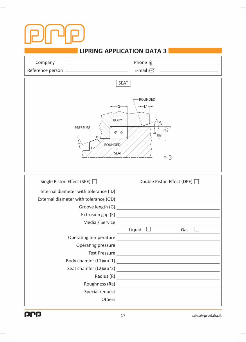
LIPRING APPLICATION DATA 3
Company
Internal diameter with tolerance (ID)
External diameter with tolerance (OD)
Groove length (G)
Extrusion gap (E)
Media / Service
Single Piston Effect (SPE) Double Piston Effect (DPE)
Operating temperature
Operating pressure
Test Pressure
Body chamfer (L1)x(α°1)
Seat chamfer (L2)x(α°2)
Radius (R)
Roughness (Ra)
Special request
Others
Phone
Reference person E-mail
SEAT
Liquid Gas
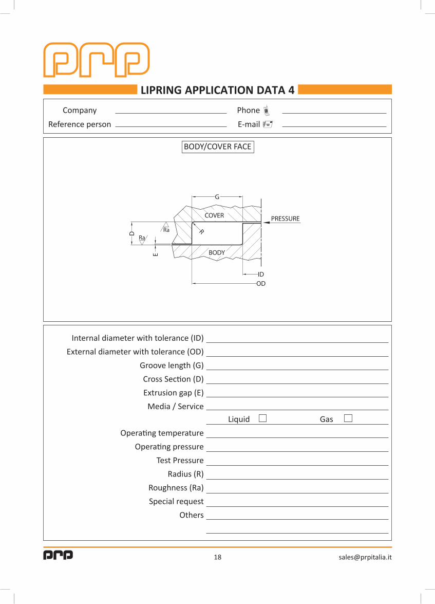
LIPRING APPLICATION DATA 4
Company
Internal diameter with tolerance (ID)
External diameter with tolerance (OD)
Groove length (G)
Cross Section (D)
Extrusion gap (E)
Media / Service
Operating temperature
Operating pressure
Test Pressure
Radius (R)
Roughness (Ra)
Special request
Others
Phone
Reference person E-mail
BODY/COVER FACE
Liquid Gas
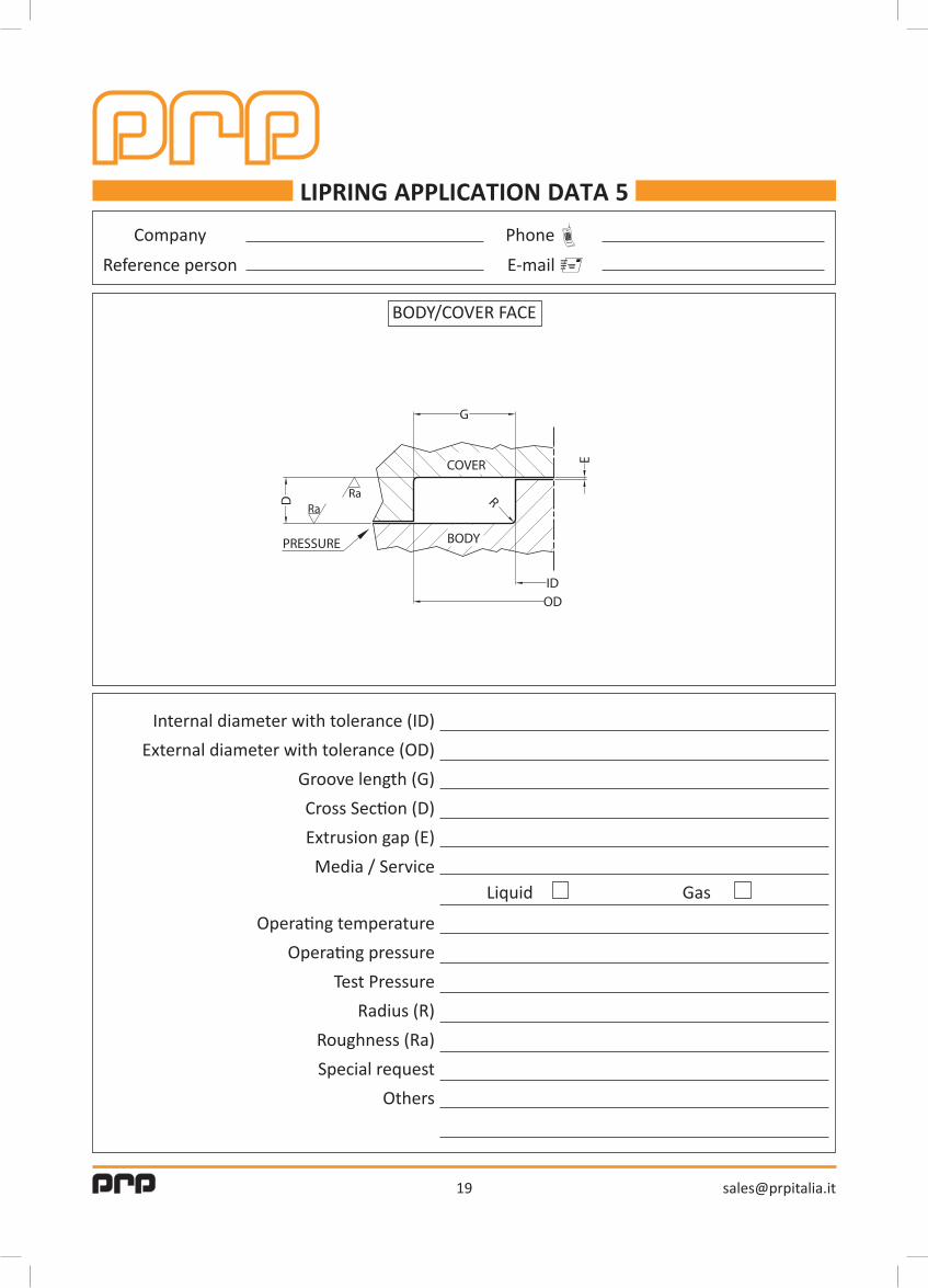
LIPRING APPLICATION DATA 5
Company
Internal diameter with tolerance (ID)
External diameter with tolerance (OD)
Groove length (G)
Cross Section (D)
Extrusion gap (E)
Media / Service
Operating temperature
Operating pressure
Test Pressure
Radius (R)
Roughness (Ra)
Special request
Others
Phone
Reference person E-mail
BODY/COVER FACE
Liquid Gas

The data and tables shown in this catalog are based upon information from material suppliers and careful examination of available publications and are believed to be accurate and reliable; however, it is the user’s responsibility to determine suitability for use.You should thoroughly test any proposed use of our seals and indipendently conclude satisfactory performance in your application.


www.carco.it
Certified quality system UNI EN ISO 9001
R
Carco HeadquartersBasiano (Italy)[email protected].: +39 02 95760331
PrpBasiano (Italy)[email protected].: +39 02 48702970
Carco GmbHHamburg (Germany)[email protected].: +49 40 21985855
Carco America LLCSharon Center (OH)[email protected].: +1 330 419 1003
Carco Asia Ltd.Shenzhen (China)[email protected].: +86 755-84594011
ICT21Les Pennes Mirabeau (France)[email protected].: +33 442772857