seanet pro - software manual - tritech | outstanding ... · pdf fileseanet pro software...
TRANSCRIPT

Seanet Pro
0706-SOM-00001-01 Tritech International Ltd. Page 1 of 42
Seanet Pro
Software Manual

Seanet Pro
0706-SOM-00001-01 Tritech International Ltd. Page 1 of 42
Table of Contents
Help & Support ....................................................................................................... 3Warning Symbols .................................................................................................... 41. Introduction ......................................................................................................... 5
1.1. Features .................................................................................................... 51.2. Capabilities ............................................................................................... 5
2. Installing & Configuring Seanet Pro .................................................................. 72.1. Configuration Details ............................................................................... 72.2. System Requirements ............................................................................... 72.3. Software Installation ................................................................................ 7
2.3.1. Seanet SCU Installation ................................................................ 72.3.2. PC or Laptop Installation .............................................................. 82.3.3. Uninstalling the software ............................................................ 10
3. Operating Seanet Pro ........................................................................................ 113.1. General Information and Operating Details ........................................... 113.2. Seanet System Display .......................................................................... 11
3.2.1. Main Screen ................................................................................ 113.2.2. Toolbar Shortcut Buttons ............................................................ 123.2.3. Main Menu .................................................................................. 143.2.4. Print Function .............................................................................. 173.2.5. Environment Setup ...................................................................... 183.2.6. Log Function ............................................................................... 183.2.7. Colour Setup ............................................................................... 193.2.8. GPS Display ................................................................................ 203.2.9. Compass Display ......................................................................... 223.2.10. Aux Device Display .................................................................. 223.2.11. Status Bar .................................................................................. 233.2.12. Sidebar ....................................................................................... 243.2.13. Load/Save Settings .................................................................... 26
3.3. Configuring the Optional Video Input ................................................... 263.3.1. Video Application Tools ............................................................. 273.3.2. Recording the Video ................................................................... 283.3.3. Video Capture Settings ............................................................... 293.3.4. Video Compression ..................................................................... 293.3.5. Log Frame Rate .......................................................................... 303.3.6. Video Frame Resolution ............................................................. 303.3.7. AVI File Sizes ............................................................................ 31
4. Seanet Setup ...................................................................................................... 324.1. Configuration Using Seanet Setup ......................................................... 324.2. Re-Programming Nodes ......................................................................... 33
4.2.1. To Re-Program a Node ............................................................... 334.2.2. To Change a Node Number ........................................................ 34
4.3. Changing System Settings ..................................................................... 364.3.1. General Setting Information ........................................................ 364.3.2. Configuring a COM Port for 3rd Party Devices ......................... 37
5. Troubleshooting ................................................................................................ 39Glossary of Terminology ...................................................................................... 40

Seanet Pro
0706-SOM-00001-01 Tritech International Ltd. Page 2 of 42
Warranty Statement ............................................................................................... 41Copyright Statement .............................................................................................. 42

Seanet Pro
0706-SOM-00001-01 Tritech International Ltd. Page 3 of 42
Help & SupportFirst please read this manual thoroughly (particularly the Troubleshooting section).For Warranty information please see the Warranty Statement at the end of the manual.
If your question or problem is still not answered then Tritech International Ltd canbe contacted as follows:
Mail Tritech International LtdPeregrine RoadWesthill Business ParkWesthill, AberdeenAB32 6JL, UK
Telephone ++44(0)1224 744 111
Fax ++44(0)1224 741 771
Email [email protected]
Website www.tritech.co.uk
Prior to contacting Tritech International Ltd Technical Support service, please ensurethat you have the following details to hand:
1. Serial Numbers of the Unit and any Tritech International Ltd equipment connecteddirectly or indirectly to it.
2. Software/Firmware Revision Numbers.
3. Fault Description.
4. Any remedial action implemented.
Please also note the following:
• The name of the organisation which purchased this system is held on record atTritech International Ltd and details of new software or hardware packages willbe announced at regular intervals, however, due to the expansion of equipmentcapabilities and the fact that new sub-modules are continually being introduced,this manual may not detail every aspect of operation.
• Depending on the module, free upgrades may be offered in keeping with our policyof maintaining the highest levels of customer support.
• Tritech International Ltd can only undertake to provide software support ofsystems loaded with the Microsoft Windows™ Operating System and SeanetPro software in accordance with the instructions given in this manual. It is thecustomer's responsibility to ensure the compatibility of any other package that theymay choose to load.

Seanet Pro
0706-SOM-00001-01 Tritech International Ltd. Page 4 of 42
Warning SymbolsThroughout this manual the following symbols may be used where applicable todenote any particular hazards or areas which should be given special attention:
Note
This symbol highlights anything which would be of particular interest tothe reader or provides extra information outside of the current topic.
Important
When this is shown there is potential to cause harm to the devicedue to static discharge. The components should not be handled withoutappropriate protection to prevent such a discharge occurring.
Caution
This highlights areas where extra care is needed to ensure that certaindelicate components are not damaged.
Warning
DANGER OF INJURY TO SELF OR OTHERS
Where this symbol is present there is a serious risk of injury or loss of life.Care should be taken to follow the instructions correctly and also conducta separate Risk Assessment prior to commencing work.

Seanet Pro
0706-SOM-00001-01 Tritech International Ltd. Page 5 of 42
1. IntroductionSeanet Pro is the latest in a line of similar survey packages from Tritech InternationalLtd and follows on from previous WINSON and SONV3 surface display applications.Much of the functionality of these earlier packages has been built into Seanet Pro,along with increased functionality and an enhanced user interface.
It is possible to transfer sensors such as SeaKing and SeaPrince heads between theearlier SONV3 system and Seanet Pro. Transferring heads will usually first require adevice re-program which is handled in the Setup application of each system. Ensurethat when transferring heads they appear in the Setup node table with Status of OK(Seanet) or Upto date (SONV3).
NoteNewer devices such as the Sub Bottom Profiler, MicronNav, Gemini,SeaHub or Hammerhead will only operate under Seanet Pro. If in doubt,contact Tritech International Ltd for more details.
1.1. Features
• Fully integrated into the Windows Operating Systems (2000/XP/7).
• Intuitive look and feel.
• Fast and powerful program interface.
• Window resizing and multi-display capability.
• LAN interface options for network remote access.
• On-screen toolbars with quick access buttons for Logging, Printing, etc.
• On-screen "elastic-band" target measurements and markers.
• Video interfacing.
• Sonar scan enhancement tools and true acoustic zoom function.
• Improved serial device input and display.
• Integration and conversion of position data input.
• User configurable multi-device applications
1.2. Capabilities
Seanet Pro can simultaneously run and display several combinations of ImagingSonar, Profiling Sonar, USBL Positioning, Bathymetric and Sidescan sensors.
By default the interface uses an ARCNET protocol to connect to the subsea devicesallowing a standard data rate of 156kBaud (max cable length 1200m) and is

Introduction Seanet Pro
0706-SOM-00001-01 Tritech International Ltd. Page 6 of 42
compatible with fibre-optic interfaces, other baud rates available for longer cablelengths, RS232 or RS485 serial communication.
Auxilliary devices can be connected via an RS232 serial port and the data-streamsconverted into visual output on the Seanet Pro display, examples include compasses,GPS devices and attitude sensors.
Seanet Pro has data logging and playback facilities which can be used to recordand replay all data from subsea sensors such as SeaKing DFS Sonar, DFP Profiler,Sidescan and Bathy and also auxiliary device inputs, such as NMEA 1083.
Seanet Setup is used to display status of all connected nodes and to download newsoftware and firmware upgrades into the subsea sensor heads onboard Flash RAMor FPGA module.

Seanet Pro
0706-SOM-00001-01 Tritech International Ltd. Page 7 of 42
2. Installing & Configuring Seanet Pro
2.1. Configuration Details
The Seanet Pro software will be supplied on an Installation CD (PC systems) or ZIPRestore Disk (SCU systems). Also provided on these disks will be electronic copiesof manuals and required drivers for AIF cards, SeaHub etc.
At regular intervals, updated versions of the Seanet Pro software will be announcedby Tritech. Free upgrades will be offered to existing users; this is in keeping with ourpolicy of maintaining the highest levels of customer support. Such updates will bemade available for download from the Tritech web-site; www.tritech.co.uk
2.2. System Requirements
The Seanet Pro software should be installed on a system with the following minimumspecification:
• Pentium III 800MHz or above (dual core CPU recommended for Gemini).
• Windows 2000, XP or 7.
• 256MB RAM for Windows 2000/XP, 1GB RAM for Windows 7.
• 1024 x 768 Resolution or above, High or True Colour.
• 50MB free hard disk space (plus additional for logging).
• CD Drive for PC installation.
• 1 spare PCI slot for AIF V4 Card, or spare USB 2.0 Port for SeaHub interface, or9-pin RS-232 ‘D’ port for SKIM-100 interface.
• Available Serial Port(s) for optional 3rd party device interfaces.
NoteDue to the discontinuation of Windows 98 and related support issues,current versions of Seanet Pro will no longer install on this platform.
2.3. Software Installation
The Seanet Pro software can either be installed on Tritech International Ltd SeanetSCUs installed with Windows XP Embedded or Windows 7 Embedded (dependingon SCU version), or alternatively be installed to a PC based surface unit or laptopcomputer.
2.3.1. Seanet SCU Installation
The Seanet SCU will be pre-installed with the Windows Embedded operating systemand Seanet Pro software. Seanet Pro can be re-installed from the disk partition, or

Installing & Configuring Seanet Pro Seanet Pro
0706-SOM-00001-01 Tritech International Ltd. Page 8 of 42
a complete system reset can be used to restore the device back to factory defaults.Refer to the SCU manual for more information on how to re-install the software (forSCUv4 devices this will involve using a Zip disk, SCUv5 uses an in-built flash drive).
NoteConsult the Seanet SCU product manual for more details and guidelineson installing, re-installing or repairing the software build includingWindows operating system and Seanet Pro software.
2.3.2. PC or Laptop Installation
The PC or Laptop computer should be loaded with a standard version of Windows2000, XP or 7. If for any reason it is necessary to reload the Seanet Pro software, thisshould be done using the installation CD supplied. Follow the setup dialog duringinstallation.
The Seanet Pro software can be installed or reloaded as follows:
1. Insert the Seanet Pro Installation CDinto the CD-ROM drive. If the CDauto-runs then a menu page will appearprompting to select the installationtype. If Autorun is disabled onthe computer, then manually runthe Setup.exe file to begin theinstallation.
2. There are 2 Seanet Pro installationtypes:
• For SeaHub, Hammerhead, or directCOM Port connections, Select theSerial RS232 Installationtype.
• For AIF Card interfaces orSCU, select the AIF CardInstallation type.
NoteTo install the Seanet Pro software, the computer must be logged on withAdministrator rights.

Installing & Configuring Seanet Pro Seanet Pro
0706-SOM-00001-01 Tritech International Ltd. Page 9 of 42
3. When the installation program starts,click Next to continue.
4. Read the license agreement and ifyou agree to the terms select theYES option, to allow you to clickNext. Click Next to continue. Choosethe installation destination directory.By default this will be C:\ProgramFiles\SeanetV2. Click the browsebutton if you wish to change thislocation. Click Next to continue.
5. Choose the installation destinationdirectory and click Next to continue.
6. Installation will proceed to copyprogram files and drivers onto yourcomputer. Entries will be made in theWindows Registry. This process maytake several minutes. Two desktop iconswill be created during the installation
• Seanet Pro is the main dataacquisition and logging application.
• Seanet Setup is used to verify deviceconnection, re-configure devices andre-program them with updatedsoftware.

Installing & Configuring Seanet Pro Seanet Pro
0706-SOM-00001-01 Tritech International Ltd. Page 10 of 42
7. Once files are copied, you will beprompted to restart the computer.Click Finish to reboot immediately.Rebooting may be deferred by selectingNo, then clicking Finish.
8. The Screen resolution should be set to a recommended 1280x1024 at either 16-bit or 32-bit colours.
2.3.3. Uninstalling the software
To Remove the Seanet Pro software:
1. Open the Windows Control Panel, and select Uninstall a program fromthe Programs tab. (Note: use Add or Remove Programs in Windows XP).
2. To remove the Seanet software, select Seanet Pro from the list, and click theUninstall button.
3. When prompted click the Yes button to confirm un-installation. Un-installationwill commence.
4. Click Close when complete to finish the task.

Seanet Pro
0706-SOM-00001-01 Tritech International Ltd. Page 11 of 42
3. Operating Seanet Pro
3.1. General Information and Operating Details
Once a system has been installed in conjunction with the relevant sections of thismanual, the subsea sensors and optional surface interfaces can be connected andpowered. The sensors can be tested in air by powering up and observing thatcommunications is established with the surface Seanet Pro software application.
When running the Seanet Pro application and with all subsea heads switched on, itmay take a few seconds for the heads and other devices such as AIF card, SeaHub,RAT etc to become established and start communicating correctly. Until this time,the Status Bar will display a Timeout (‘Timeout Node xx’) message for each Nodethat it is trying to communicate with. These messages will disappear as each subseaelement checks out OK.
If the RAT or subsea elements are not powered up, not present, or have a faultsomewhere, then error messages (i.e. ‘xxx N/A’, ‘xxx Bad’) will be shown in thestatus bar boxes on the bottom of the display. If error messages appear, check thatall the system parts are connected and that all leads/cables are correctly installed.When error messages continue to appear then there is a fault and the Troubleshootingsection should be referred to.
The following sections of this manual will describe the general software controls inaddition to installation and connection instructions. Further, separate manual sectionswill describe operation of each of the subsea Sensors and their connection details.
3.2. Seanet System Display
A general description of the screen layout and its controls will now be given. Thescreen menus and controls can all be accessed with Mouse pointer and keyboard. Ifthe system Remote Access Terminal (RAT) is installed, then subsea device controlssuch as Gain and Range Scale can be adjusted using the RAT dials and Functionbuttons. The RAT Togglestick will provide additional control by providing the Mousepointer interface.
There are a number of subsea devices that can be connected to the Seanet SCUincluding Imaging Sonar, Profiler, Bathy and Sidescan. Refer to the Operator’smanual section that was supplied with each of these devices for specific details ontheir screen controls and functions. For the example below, an Imaging Sonar displaywill be used.
3.2.1. Main Screen
The Seanet Pro application can be run from the Programs group in the WindowsStart menu or from the desktop by double clicking on the shortcut icon.
The Seanet Pro screen display shown below is a Gemini, SeaKing & Bathymetricapplication, although the view will vary depending on the applications chosen, eachapplication will have a similar layout.

Operating Seanet Pro Seanet Pro
0706-SOM-00001-01 Tritech International Ltd. Page 12 of 42
The main areas of the display are:
1. Display Header This part of the screen is used for system/softwareidentification.
2. Menu Bar This is where system set-up functions can be accessed. Printing,Application selection, Colour Scheme setup and Logging are some of the featuresthat can be accessed in this screen area.
3. Settings Bar This is where the Sensor can be controlled and configured. TheSettings bar is on top of every display window for each device that is connected tothe system. It includes a Tools Setup button, Led indicator (Pause/Go) and RATdials and buttons
4. Status Bar This part of the screen is used to display system status information,typically the AIF card interface status, Logging status/progress and Job specificinformation.
5. Sensor Display Area This part of the screen is where the main Sensordata is displayed. Other pertinent data such as Range Scale, Cursor and statusmessages pertaining to the Sensor may also be displayed within this area - Refer tothe manual section provided with each Sensor for further details of its display area.
6. Sidebar This is where Serial input data and user text can be displayed. This barcan be placed on the Left or Right hand side with RHS the default setting. Theoperator can choose to have this bar visible or not and it can also be folded away.
3.2.2. Toolbar Shortcut Buttons
On the left hand edge of the main Seanet Pro display is a toolbar containing iconsas detailed below:
Operating Seanet Pro Seanet Pro
0706-SOM-00001-01 Tritech International Ltd. Page 13 of 42
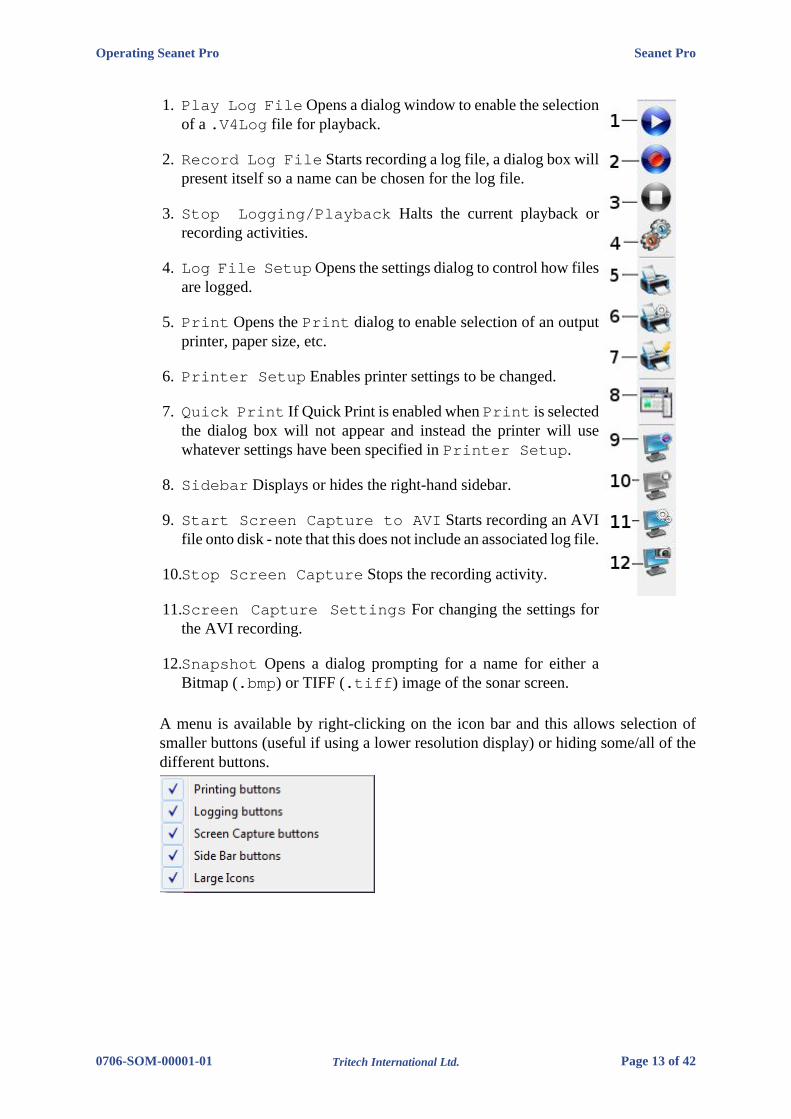
1. Play Log File Opens a dialog window to enable the selectionof a .V4Log file for playback.
2. Record Log File Starts recording a log file, a dialog box willpresent itself so a name can be chosen for the log file.
3. Stop Logging/Playback Halts the current playback orrecording activities.
4. Log File Setup Opens the settings dialog to control how filesare logged.
5. Print Opens the Print dialog to enable selection of an outputprinter, paper size, etc.
6. Printer Setup Enables printer settings to be changed.
7. Quick Print If Quick Print is enabled when Print is selectedthe dialog box will not appear and instead the printer will usewhatever settings have been specified in Printer Setup.
8. Sidebar Displays or hides the right-hand sidebar.
9. Start Screen Capture to AVI Starts recording an AVIfile onto disk - note that this does not include an associated log file.
10.Stop Screen Capture Stops the recording activity.
11.Screen Capture Settings For changing the settings forthe AVI recording.
12.Snapshot Opens a dialog prompting for a name for either aBitmap (.bmp) or TIFF (.tiff) image of the sonar screen.
A menu is available by right-clicking on the icon bar and this allows selection ofsmaller buttons (useful if using a lower resolution display) or hiding some/all of thedifferent buttons.

Operating Seanet Pro Seanet Pro
0706-SOM-00001-01 Tritech International Ltd. Page 14 of 42
3.2.3. Main Menu
1. Print Output screenshot to printer.
2. Screen Capture Screen to AVI or save screen to Bitmap/Tiff.
3. Exit Used to exit program.
1. Load/Save Settings Save and Load the current display and device settings(up to 8 can be saved).
2. Environment Used to enter environmental parameters such as system VelocityOf Sound.
3. Always On Top Main Screen is Always on Top of Windows desktop.
This Menu Item will only be present in Seanet Pro and not from running Seanet Setupfrom the desktop icon. Application examples include Single Sonar, SonarProfiler and Sonar Bathy Profiler. There is also an ApplicationWizard available at the top of the list which can be used to create user applicationsfor required device combinations.

Operating Seanet Pro Seanet Pro
0706-SOM-00001-01 Tritech International Ltd. Page 15 of 42
1. GPS Popup Form to display GPS data received through a COM port.
2. Compass Popup Form to display Compass data received through a COM port.
3. Auxiliary Device Popup Form to display Aux Device data (i.e. DigiquartzPressure Sensor or PA/NMEA Altimeter data) received through a COM port.
4. Com Setup Configure and Enable COM ports for various serial inputs/devicesincluding GPS, Pipetracker, Barometer and Compass.
5. GPS Diagnostic Terminal window for viewing received serial data.
6. Compass Diagnostic Terminal window for viewing received serial data.
7. Auxiliary Device Diagnostic Terminal window for viewing receivedserial data.
8. Barometer Diagnostic Terminal window for viewing received serial data.
1. Sidebar Enable/Disable the Sidebar. Note: In certain applications, i.e. ‘SonarVideo’, the Sidebar will be opened and docked to the blank ¼ window panel filler.
2. Toolbars There are several toolbars containing shortcut buttons which can bedisplayed in the Menu Bar area or docked to the sides of the Display Area. Fordetails see the "Toolbar Shortcut Buttons" section above.

Operating Seanet Pro Seanet Pro
0706-SOM-00001-01 Tritech International Ltd. Page 16 of 42
1. Play Use to play back recorded log data (follow the on screen display).
2. Record Use to record Sonar data (follow the on screen display).
3. Stop Stop recording and/or Auto Logging.
4. Setup Select file options for recording log files (Follow the on screen display).
Sonar (this will be renamed for other devices, e.g. Sidescan, Profiler, Bathy)
1. Colours Use to select a saved colour scheme.
2. Colour Setup Use to configure the existing colour scheme or create a newcolour scheme.
Windows (only functional in multi-Sensor Applications)
1. Sonar Switch focus to Sonar Display window.
2. Other Will be replaced with name of another Sensor in a Multi-SensorApplication.

Operating Seanet Pro Seanet Pro
0706-SOM-00001-01 Tritech International Ltd. Page 17 of 42
The Sound menu enables an acoustic representation of the visuals presented on theMain Screen of the Seanet Pro application. Clicking on Setup allows configurationof how this sound is represented.
1. About Seanet Gives details of program and version number.
2. Seanet Guide Seanet Help file.
3. System Information Gives information of computer resources in use.
3.2.4. Print Function
This is accessed by navigating to the File menu and selecting Print
1. Quick Print On When printing the Print Setup dialog box will not appearand default printer and its settings are chosen.
2. Setup Printer – Select and setup the Windows Printer.
3. To Printer – Print to Windows Printer. When Quick Print On is set toOff, a setup dialog will appear allowing the user to select printer and set optionsbefore printing.
CautionPrinting may take a few moments during which sonar updates aresuspended. It is therefore not advisable to make printouts during actualunderwater operations unless it is safe to do so.

Operating Seanet Pro Seanet Pro
0706-SOM-00001-01 Tritech International Ltd. Page 18 of 42
3.2.5. Environment Setup
This is accessed by navigating to Environment in the Settings menu. Thisis where all the environmental values should be applied for use in various deviceapplications. Only the Velocity of Sound (V.O.S) will apply for a Sonar application– the remaining entries are for Bathymetric calculations.
1. V.O.S. System value applied to all acoustic devices to correct plotter ranges.Applies to Sonar and Profiler and can also be applied in MicronNav calculations.
2. Density Applied to SK701 Bathymetric (no CT probe) depth calculations.
3. Latitude Applied in the Loc Gravity calculation which is then applied inBathymetric depth calculations.
4. Barometer Applied to Bathymetric depth calculations when a Barometerinterface is not used. If Barometer interface is installed then Offset and Heightvalues should be entered.
3.2.6. Log Function
This is accessed via the Log menu on the Menu bar:
With Logging de-activated, click on Play to replay a Log file or click Record tostart recording a new Log file. When a new Log file is opened for recording, the filename will default to a Date and Time format.
During recording, the Play feature will be locked out and Record option willbe ticked, highlighting a recording is active. During recording the status bar (onthe bottom of the display) indicates the current log file size. Clicking on Stop ordeselecting Record will halt recording.
During log file playback, the file details will be displayed in the replay dialog. ThePause button temporarily halts the log file and Continuous Loop plays itcontinuously. There is also a (clock) button to select play back at real time speed.The slider bar controls the replay speed.

Operating Seanet Pro Seanet Pro
0706-SOM-00001-01 Tritech International Ltd. Page 19 of 42
NoteThe name of the log file is displayed in the replay dialog caption bar.
Setup allows the directory where log files are to be stored to be changed and seta maximum file size selected. The time-stamping of saved records can be in eitherLocal or UTC time.
There is an Auto LogOn option to allow auto logging as soon as the system starts.There is a check-box to activate this (On/Off) via the Rat 'F7' button.
The user can specify a Base Name or choose a Date/Time format to prefix theautomatically generated file names.
3.2.7. Colour Setup
This is accessed via Colour Setup which is found in the Sonar menu.
NoteFor other device applications such as Profiler, Bathymetric orSidescan, the Sonar menu item will be replaced with Profiler,Bathymetric, Sidescan as appropriate.
Click on the New button to start a new colour scheme or change the colours of thecurrent scheme (indicated in the drop-down list, Colour6 in this case). There are7 factory preset colour schemes which cannot be altered. If you try to alter theseschemes then a dialog will prompt you to save to a new scheme if and when you tryto save or apply changes.

Operating Seanet Pro Seanet Pro
0706-SOM-00001-01 Tritech International Ltd. Page 20 of 42
The various colour boxes can be clicked on to configure a new colour for that item.The 3 slider bars are used to set the new RGB colour levels for each item and theApply button is used to confirm the changes. Clicking on OK accepts all changesand exits the dialog.
3.2.8. GPS Display
This is accessed via the GPS in the Utilities menu.
When enabled, the GPS dialog will be displayed.
1. Latitude or Eastings
2. Longitude or Northings
3. Zone
4. Course Over Ground
5. Speed Over Ground
6. Heading
7. GPS Input is used to select and configure the GPS input messages.
8. Diagnostics flashes green when there is an incoming GPS packet.
The GPS input COM port is configured from Com Setup.

Operating Seanet Pro Seanet Pro
0706-SOM-00001-01 Tritech International Ltd. Page 21 of 42
The GPS Setup panel is accessed by clicking on the GPS Input button and is wherethe NMEA 0183 message type can be selected.
All position data updates displayed in the GPS panel will be recorded when thelogging function is used to record device data and GPS data.
The GPS Setup panel contains 4 drop-down menus for selecting NMEA 0183message types for Latitude/Longitude, COG/SOG, Heading and SystemTime.
It is possible to set the system time via any of the listed NMEA messages and this willupdate the clock within the sensor device. This is used to time synchronise output datastrings to a survey computer or if log data containing both device and GPS positiondata is to be post-processed.
The GPS Setup panel includes the option to convert and display the incoming Lat/Lon positions in Eastings/Northings format using a UTM or OSGB conversion.
There is also facility to select the particular Ellipsoid to apply in the UTMconversion equation with option to apply a geodetic datum shift. By ticking the UserDefined Datum Shift check-box, an Edit button will appear:
Clicking on this button will display the User Defined Geodetic Shift panelwhere parameters can be entered for the required datum shift.

Operating Seanet Pro Seanet Pro
0706-SOM-00001-01 Tritech International Ltd. Page 22 of 42
Once parameters have been entered, press Return to go back to the previous setuppanel.
A terminal window can also be opened to display the incoming GPS data strings.This is opened by clicking on GPS Diagnostic in the Utilities menu. Theterminal window will appear as follows:
3.2.9. Compass Display
This is accessed via the Utilities menu by clicking on Compass.
When enabled, a popup compass form will be displayed. This will display thecompass data, received through a surface COM port, including Heading, Pitch andRoll (all in degrees).
All data updates displayed in the compass panel will be recorded when the loggingfunction is used to record device data.
Also, on the popup compass form there is a diagnostic button which flashes greenwhen there is an incoming GPS packet.
A Terminal window can also be opened to display the incoming Compass data strings.This is opened from Compass Diagnostic in the Utilities menu.
3.2.10. Aux Device Display
This is accessed via the Utilities menu by clicking on Auxiliary Device.
When enabled, a popup Text Box form will be displayed. This can be used to displayASCII character data from a serial device up to a maximum of 100 characters in lengthand terminated with a <Carriage Return><Line Feed> (ASCII code 13 followed bycode 10).

Operating Seanet Pro Seanet Pro
0706-SOM-00001-01 Tritech International Ltd. Page 23 of 42
The Aux Device form can process and display altitude data (in metres), receivedthrough a surface COM port, from a PA or NMEA Altimeter; Digiquartz pressuredata will also be converted to display a depth in metres. The values entered intothe Environment dialog (accessed through the Settings menu) for density,barometer and local gravity will also be applied to the calculation of depth.
• Use As Remote Event to send the Aux device data to the Sidescan Sonar orSub-Bottom Profiler plotter as a ‘Remote Event’ for annotation.
• View Raw Data to view the raw data string from known devices such as a PAAltimeter or Digiquartz instead of the Seanet processed string.
All data updates displayed in the Aux Device text panel will be recorded when thelogging function is used to record device data.
The Diagnostic Led flashes green when there is an incoming Aux packet. A Terminalwindow can also be opened to display the incoming data strings. This is opened fromthe Utilities menu by selecting Auxiliary Device Diagnostic.
3.2.11. Status Bar
1. Date and time.
2. Status of interface card (AIF card).
3. ARCNET LAN Timeout counter
4. Status of Serial COM port inputs.
5. Status of Remote Access Terminal (RAT).
6. Sensor Status.
Various error codes are reported in the status bar at the bottom of the screen. Thesehelp the user determine any faults with equipment or cabling, as a guide to makingany corrections or replacements
Status and error codes:
No Aif The AIF card is not installed or not configured/enabledcorrectly. This status will also appear when using theSeaHub serial port interface instead of the AIF cardinterface.
Rat Ok Remote Access Terminal (RAT) is connected andcommunicating okay.
Rat N/A RAT is not connected or there is a connection problem.

Operating Seanet Pro Seanet Pro
0706-SOM-00001-01 Tritech International Ltd. Page 24 of 42
No COM Will display if only an AIF Card interface is in use orno COM Port has yet been opened (e.g. No “Aif” deviceyet enabled from Com Setup accessed through theUtilities menu).
Com OK For SeaHub or COM Port interface; A COM port hasbeen opened and is functioning correctly.
Com Bad For SeaHub or COM Port interface; The COM portcannot be opened – it may already be in use by anotherapplication or may have a problem.
Com AIF Error TMO For SeaHub or COM Port device interface; the device isnot responding (check it is connected and powered).
Timeout x There is no communication with head node x
3.2.12. Sidebar
This can be enabled or disabled from the View menu and toggling the Sidebaroption. Alternatively, the pin button on the top right of the sidebar can be toggled topermanently pin or fold it away. The sidebar can also be picked up by its caption barand docked to either the left or right hand side of the display area.
Clicking on the pin button will fold away and hide the Sidebar.Moving the mouse over the Sidebar label will cause it to rollout. Click the pin again to permanently pin it back in place.
The sidebar is the viewing area for Client Icons and User Text Boxes.These can be set via an SK REMV4 command (‘:SB’ Set Button Bar) receivedthrough the serial COM port.

Operating Seanet Pro Seanet Pro
0706-SOM-00001-01 Tritech International Ltd. Page 25 of 42
Up to 8 types of pre-determined serial input string may be displayed and these includeGPS and Compass data inputs.
Client Icons. In addition to the fixed Seanet Pro logo, there are 3 icons thatcan be configured by the client. Each icon is 32x32 pixels and can be loaded by adouble-click which will bring up a Set Icon dialog. Select Icon Number in aloaded .EXE or .ICL file as shown or select a 32x32 .ICO file to display.
User Text Boxes. Eight editable text boxes are available to display job orreminder information. Double-click on any text box to bring up an editor where textcan be entered.
Text can also be passed to these boxes using the ‘:SB’ SK REMV4 serial command.
Serial Input Data A maximum of 8 serial input display boxes can be selected(+ / -). The drop-down menu in each box will select the particular type of input todisplay. Cog/Sog from a GPS message and Pitch/Roll from an attitude sensorare shown, other inputs include Heading from a NMEA HDT/HDM string, Depthcalculated from Digiquartz Pressure Sensor readings and Altitude from a PA orNMEA Altimeter.
GPS Data Input. Click on this icon to open the GPS Setup dialog.

Operating Seanet Pro Seanet Pro
0706-SOM-00001-01 Tritech International Ltd. Page 26 of 42
To configure a COM Port for serial input data, navigate to Com Setup in theUtilities menu.
3.2.13. Load/Save Settings
This is where the screen configuration can be saved and previously savedconfigurations can be loaded. This is accessed via the Settings menu on the Menu bar.
Place the mouse pointer over the Load Settings menu item, to bring up a sub-menu listing all the previously stored configuration settings.
There is a default setting that will always appear in the list and cannot be deleted.This is the setting to be used for reverting the system back to factory defaults.
In addition to the factory default up to 8 different configurations can be saved. Tosave the current application and form layout, click on the Save Config button.A prompt will be displayed to enter the configuration name, with a default name of"User x" initially given, where "x" is the configuration number.
Click on OK to store the current settings to file, where they can later be loaded usingthe Load Settings. Disused configurations can also be deleted from the SaveConfiguration form by highlighting the configuration to be deleted and thenselecting Delete Config.
3.3. Configuring the Optional Video Input
The Seanet SCU or customer supplied PC can be installed with an optional videoinput capture card. This card will receive PAL/NTSC video from a composite sourceand display the video in a window adjacent to other devices such as Sonar. The

Operating Seanet Pro Seanet Pro
0706-SOM-00001-01 Tritech International Ltd. Page 27 of 42
Application menu allows selection of layouts which contain a video displayscreen.
3.3.1. Video Application Tools
To configure the video and capture settings, click on the tools icon on the left of thevideo settings bar to open the menu:
Video Input lists the video inputs (or capture devices) that are installed intoWindows. These may include internal capture cards, external USB devices and built-in webcams (if using a laptop computer).
If there is a capture device that has more than one driver installed then it may benecessary to try out the different drivers to find one that is correctly working. If thereis a choice of drivers then it is recommended to opt for the driver labelled 'WDM' or'Video' and not 'VFW'. A VFW driver (Video For Windows) is a driver that is usedwith older operating systems. Although it may work, the same performance will notbe obtained compared with using more recent operating system drivers.
Video Display is called out from thedevice driver and will change accordingto capture device. This dialog will notalways be available and will depend onthe source capture device that is currentlyselected from the Video Input sub-menu.
NoteThe Output Size can affect the display quality of the video preview.If the video display appears distorted try changing Color Space/Compression and Output Size to rectify (RGB24 and 640x480 arethe recommended settings).

Operating Seanet Pro Seanet Pro
0706-SOM-00001-01 Tritech International Ltd. Page 28 of 42
Video Configure is also called outfrom the device driver and will changeaccording to capture device.
Log Options The video footage islogged into an .AVI file format withsame filename as the main Seanet Pro.V4Log log file. A frame index recordis now logged into the log file which isused during playback to synchronise thevideo to any other sensor data that is beingextracted from the log. if no other sensordata is present then video will be replayedon it’s own.
• Tick the Enable Video Logging box to enable the video recording whenevera new log session is opened (by going to the Log menu and selecting Record).
• The Log Frame Rate, Resolution and Compression should then beconfigured, which will affect the video recording. A default video codec is installedwhich has been configured to capture good quality video at a relatively low datacapacity. It is recommended that this codec be used although other codecs can beselected by selecting Other and clicking on Set Codec.
• Tick the Enable Audio Logging box to record audio from a connectedMicrophone or sound recording device. Such a device will first need to beconfigured and selected in Windows (e.g. Control Panel – Sounds and AudioDevices – ‘Audio’ tab page – ‘Sound Recording’/’Sound Playback’). Audio willbe sampled default at 8-bit, 11kHz, PCM format.
Video Source. A number of capture devices have multiple input sources. Thesesources can be for inputs from composite or S-VHS feeds and also from terrestrialTV stations (e.g. TV Tuner cards). It is important that the feed from the video camera(normally composite) is selected.
3.3.2. Recording the Video
The input video can be recorded alongside other device data such as Sonar andMicronNav. All device data is stored in the .V4Log log file. The video is recordedinto a separate “.AVI file which is saved in the same root folder as the log file. TheAVI file will be given the same filename as that of the log file.

Operating Seanet Pro Seanet Pro
0706-SOM-00001-01 Tritech International Ltd. Page 29 of 42
For example, to start recording, click on Log menu and select Record then setthe filename and path for the .V4Log file, and the video file will automatically becreated, so if there is a file named:
D:\Logs\Thu_14_Apr_16_07.V4LOG
Then video will automatically be recorded to:
D:\Logs\Thu_14_Apr_16_07.AVI
When replaying the data (click Log menu and select Play), the .V4LOG log file isselected and opened. If there is an associated .AVI file (with same filename) foundin the same folder as the .V4Log file then it will also be opened and replayed. Theplayback of both files will be simultaneous and in time synchronisation with eachother.
3.3.3. Video Capture Settings
When capturing video to a log file, there are several settings available in the ‘LogOptions’ to consider. These settings will affect the quality and size of the capturedvideo data.
It is strongly suggested that video capture using Seanet Pro is tested, and capture filessizes and rates checked and verified, before going live. The PC specification shouldalso be adequate and a suitable capture device used to give desired performance andvideo quality. Any modern computer should be capable of video capture althoughoutput performance can not always be associated with a the computer specificationand a clean re-installation of Windows can often release resources and improve theoverall performance. If purchasing a new computer for use with Seanet Pro ensurethat the storage disk to be used is capable of fast transfer speeds. For internal hard-drives SATA or SCSI should be used and externally a minimum of USB2.0 isrequired.
There is also a limiting factor in some video capture devices, in particular withsome USB models. The capture filter for the device can often share resources forboth capture and preview functions. This means that the device hardware must sharebandwidth between rendering video on the display and capturing video to file usingthe file writer. As a consequence of this sharing if the available bandwidth becomesover utilised then the preview function will begin to drop frames so that the captureelement can maintain itself (the capture function is always given priority over thepreview function). If during video capture it is seen that the video display is droppingframes (or perhaps not updating at all), but the AVI file is being written to, then itmay be the capture device that is causing the fault.
3.3.4. Video Compression
NoteSelection of the correct codec will greatly reduce AVI file sizes.

Operating Seanet Pro Seanet Pro
0706-SOM-00001-01 Tritech International Ltd. Page 30 of 42
Microsoft Windows is bundled with several video codecs. Some of these havelimited functionality and limiting performance. In tests with Seanet Pro by TritechInternational Ltd the best performance was obtained with the Cinepak® codec(developed for Microsoft by Radius).
For instance, using the Cinepak® codec can reduce video file sizes by up to 90% andmore in some cases, which is very important when long video runs are to be recordedonto limited disk storage space. Using the correct codec can bring high quality videocapture sizes down from 1GB min-1 to under 10MB min-1.
As an alternative Open Source codecs such as XVid are available. Similar toCinepak®, XVid gives high quality and relatively loss-less video capture andremarkably small file sizes and can be downloaded from www.xvid.org. This codeccould be useful if a portable solution is required, where an AVI file is to be distributedamong AppleMac, Unix or Linux machines but it does require that the codec isinstalled on the computer prior to open and playback of the file.
NoteIt is also possible to de-compress or even re-compress an AVI file post-job. A Microsoft utility named "GraphEdt.exe" is a tool than can be usedto perform this task and is available from www.microsoft.com.
To enable video compression, tick the Compression On tick box in the LogOptions page and then click on the Set Codec button to select from the list ofcodecs that are currently installed.
3.3.5. Log Frame Rate
This is the number of frames per second that is recorded to the AVI file. For capturinghigh speed moving object a frame rate of 25 frames per second is usually required.However, this can often be reduced to 15 or even 10 frames per second to giveadequate motion coverage of moving targets underwater. The benefits of reducingthe frame rate is to reduce the size of the AVI file. Also the more often the AVI isbeing written to then the more often the log file is written to which means that bothfiles are being written to simultaneously. Disk transfer speeds and bus types in thecomputer therefore need to be capable of fast transfer speeds. SATA or SCSI solidstate disks (SSD) are recommended above IDE hard drives. If using an external driveit needs to be at least USB 2.0 compliant and connected to a USB 2.0 port, and USB3.0 or eSATA is recommended.
3.3.6. Video Frame Resolution
The list of available resolutions (horizontal x vertical of the video frame) will befixed to each device type. Some capture devices will only handle a resolution up to640x480 or 720x576 using an RGB 24 colour space. It is often best to use the highestresolution available to the device and then opt to apply compression and/or a reducedframe rate to keep AVI file sizes down. If the video is only going to be displayed andor screen printed in a ¼ window within Seanet Pro, then 320x240 may be sufficient.

Operating Seanet Pro Seanet Pro
0706-SOM-00001-01 Tritech International Ltd. Page 31 of 42
3.3.7. AVI File Sizes
The video component uses DirectShow and will write AVI V2.0 files. These can beover 2.0GB in size. However, files over this size will not open in Seanet Pro andso it is strongly recommended that video capture rates are first tested before goinglive, and maximum recording time is then calculated to keep AVI file sizes withinthis limit. Seanet Pro will display a warning in the status bar when the AVI file sizereaches 1.9GB and will then auto-close the file when it reaches the 2GB limit.

Seanet Pro
0706-SOM-00001-01 Tritech International Ltd. Page 32 of 42
4. Seanet Setup
4.1. Configuration Using Seanet Setup
The Seanet Setup application can be run to check the status of devices (e.g. AIF cardand subsea sensors) currently connected and to perform other changes if directed.COM Port settings are also configured here for input of GPS and other such serialdevices where available.
The application program can be run from shortcuts found in the same locations asthe main Seanet Pro application.
When opening the Seanet Setup application, a panel will appear as below:
Each head has a node address that allows it to be recognised on the ARCNETcommunications link. The system is expecting to find a node number of 255 for theAIF card (or 252 for a SeaHub module or 254 for the SKIM-100 module) and thensensor node number(s) (node 2 is the imaging sonar head, nodes 20 & 21 are masterand slave profilers, node 40 is bathy and node 10 is sidescan).
The menu bar is the same as for the main Seanet Pro program other than a Setupmenu item is added that can be used to view the AIF Card, Gemini LAN and BinFile Settings.
Clicking on Aif Card will open the Aif Setup panel which should have thefollowing default settings

Seanet Setup Seanet Pro
0706-SOM-00001-01 Tritech International Ltd. Page 33 of 42
If using the AIF card with a SCUv4 or PC the default settings of Io Base = 330,Irq = 10 should always be shown and the Enabled tick-box should always beticked.
If a SCUv5, SeaHub or other interface box is in use then the Enabled tick-box maybe disabled.
4.2. Re-Programming Nodes
In some cases it may be necessary to update the software program installed within aSensor or to change its node number. This may be the case particularly when subseasensors are introduced from another system, hired in or taken from a spares pool.
After the node table is rebuilt in Seanet Setup, the Status column of each nodeshould appear as status OK. This will confirm that whatever is programmed into thatnode is at the same software version as that contained in the Seanet Pro program thatis loaded onto the computer. If the Status box appears with status Update, then itmeans that the node will need to be re-programmed to match the software version ofthe current version of Seanet Pro.
CautionOnly re-program nodes over short lengths of test cable (1m lenghts areavailable from Tritech International Ltd if not already supplied with thesonar head at time of purchase). Longer cables increase the risk of the databecoming corrupted in transit and could result in the sonar head becomingunusable after the update.
4.2.1. To Re-Program a Node
1. Open the Seanet Setup program and wait for a few seconds for the nodesto build.
2. Click on the Action column for the node that has Status of Update and thenselect Program.
3. Then click on OK to confirm the re-program operation

Seanet Setup Seanet Pro
0706-SOM-00001-01 Tritech International Ltd. Page 34 of 42
4. The current software program will be downloaded into the node and this will bedisplayed on the download status bar indicator.
5. Wait until the download has completed and until the table has been rebuilt. Thenode status should change from Update to OK to indicate that the download hasbeen completed.
4.2.2. To Change a Node Number
NoteThe different types of device are programmed with different ranges ofnode numbers and these devices will not operate if a node value is selectedwhich is out of this range.
Node ranges:
2 - 5 SeaKing DF Sonar, SeaPrince, Micron, Hammerhead
10 - 11 SeaKing Sidescan (Towfish)
15 - 16 SeaKing Sub Bottom Profiler
20 - 29 SeaKing DF Profiler
40 - 43 SeaKing Bathy
60 Attitude Sensor
75 MicronNav Attitude Sensor
90 MicronNav Interface Box / Dunking Transducer

Seanet Setup Seanet Pro
0706-SOM-00001-01 Tritech International Ltd. Page 35 of 42
100 - 103 Gemini Sonar
104 - 109 Gemini Profiler
252 SCUv5 or SeaHub
254 SKIM-100 Interface Box
255 ARCNET Interface Card (ISA or PCI AIFV4 card in a PC)
Changing node numbers is useful for running a multiple Sonar application when 2Sonars are connected that have the same node number. For example a dual sonarapplication using SeaKing Sonars requires that the nodes be 2 & 3, or using twoSeaKing Profilers as master and slave pair requires nodes of 20 & 21.
In both of these cases, connect one of the Sonar or Profiler heads that is to havethe node number re-programmed and then follow the procedures below to change itsnode number.
CautionOnly re-program nodes over short lengths of test cable (1m lenghts areavailable from Tritech International Ltd if not already supplied with thesonar head at time of purchase). Longer cables increase the risk of the databecoming corrupted in transit and could result in the sonar head becomingunusable after the update.
1. Open Seanet Setup and wait for a few seconds for the nodes to build.
2. Click on the Action column for the node that requires its node numberto be changed (node 2 in this case) and then select Change Node.
3. Enter the new node number to be programmed into the device.

Seanet Setup Seanet Pro
0706-SOM-00001-01 Tritech International Ltd. Page 36 of 42
4. Then click on OK to confirm the re-program operation.
5. The current software program will be downloaded into the node and this will bedisplayed on the download status bar indicator.
6. Wait until the download has completed and the table automatically rebuilds. Pressthe Rebuild button to rebuild the list and confirm that the node is showingcorrectly.
4.3. Changing System Settings
4.3.1. General Setting Information
Serial COM port settings or baud rates can be changed from several locations in theSeanet Setup program.
The AIF Interface settings can be viewed or changed by navigating to the node andselecting the Action column and then clicking on Setup.
The dialog opened will depend on which device is connected, below are examplesfor the settings accessed for a SeaHub and also an AIF card.
This is a SeaHub although SCUv5settings are very similar. Note that BaudRates is greyed out and cannot beaccessed - this is changed from the COMSetup dialog as described later.
This is the dialog box for a PCI AIF cardequipped SCUv4 or for an PCI AIF cardinstalled into a PC.
The Setup menu has 3 items as previously described and can be used to changesettings on the AIF card, a Gemini sonar, if one is connected, or the Bin Files settings.
The Utilities menu includes COM Setup for configuring serial I/O devices,such as GPS or pipetracker string inputs. This is also where the baud rates for SeaHuband other interface devices can be accessed and changed.

Seanet Setup Seanet Pro
0706-SOM-00001-01 Tritech International Ltd. Page 37 of 42
4.3.2. Configuring a COM Port for 3rd Party Devices
To display (and log) available serial device data, such as GPS data, along with thesensor data, a serial COM port must be enabled and configured for this purpose. Inthe following example, an NMEA 0183 type GPS message is to be received throughCOM1.
1. Open the Seanet Setup program by clicking on the Seanet Setup desktop shortcut.
2. Click on the Utilities menu and then select Com Setup.
3. The Channel Setup panel will be displayed with options to enable and configureCOM Ports for available devices. For instance, to setup COM 1 for GPS input, firstensure that the Enabled check-box is ticked (as shown below). Set the Baud Rateand ensure that the Status displays ‘Available’ (else select another COM Port).
• USB is the USB to serial converter
• SeaHubxxx SeaHub port (‘A’..’D’, ’Main’, ’Aux’)
• Generic Legacy COM Port and other
4. Then, click on the Settings ellipsis button (…) to open the CommunicationSettings panel to configure the port. The COM Port number and Baud rate canalso be viewed or changed.

Seanet Setup Seanet Pro
0706-SOM-00001-01 Tritech International Ltd. Page 38 of 42
Only Comm Port and Baud Rate should need to be changed.

Seanet Pro
0706-SOM-00001-01 Tritech International Ltd. Page 39 of 42
5. Troubleshooting
Symptom Likely cause Solution
Failure to boot-up Connectors are disconnected Check that all connectorsare secured. If an internalfault is suspected check theappropriate product manualfor the device in use forfurther instructions.
Continuous Status "timeout" This indicates that there isno communication with thedevice flagged
Check the power andcommunications links to theSubsea Sensor for continuityand for correct polarity,voltage and ensure that thepower supply can providesufficient current to powerall devices. If necessaryrefer to the service section tocheck that the head internalfuses have not blown. If thisoccurs on first installation payparticular attention to cableterminations and check thatyou are not exceeding therecommended cable length(1200m using the standardBaud rate).
CautionIf a cable flood is suspected, then the conductors will need to be insulationtested; the subsea units must be disconnected from the surface interface.
Seanet Pro
0706-SOM-00001-01 Tritech International Ltd. Page 40 of 42
Glossary of TerminologyAIF Card ARCNET Interface Card - an ISA or PCI card which is installed
into a PC or as part of the SCUv4. Note that SCUv5 and later usea custom ARCNET board which does not use a PCI card slot butprovides exactlyt the same functionality.
ARCNET Acronym for "Attached Resource Computer NETwork" - it is anetwork protocol similar to ethernet but with the advantage ofworking over much longer ranges.
MicronNav An Ultra Short Baseline (USBL) system for location andtracking of ROV's, divers, etc. Consists of the MicronNav 100surface control unit (similar to the SeaHub but with differentfunctionality) a "dunking transducer" which is mounted on thevessel/dockside under the waterline and a responder which ismounted on the ROV, diver, etc.
RS232, RS422 or RS485 Standard serial communication protocols.
RAT Remote Access Terminal, a device which is detachable from thefront of the Seanet SCU and can provide basic control over theSeanet Pro display.
Seanet SCU or Seanet Surface Control Unit - a specially manufactured computer whichis rack mountable and capable of processing the data from thesonar equipment running either embedded XP or Windows 7 andSeanet Pro software.
Seanet Pro The software supplied by Tritech International Ltd which iscapable of running all the sonar devices.
SeaHub An alternative to using a Seanet SCU, this device connects to alaptop or PC via USB interface, essentially this takes the signalfrom the sonar (in RS232, RS485 or ARCNET) and converts itinto a signal suitable for the USB port of the computer.
SeaKing A specific sonar produced by Tritech International Ltd but alsorefers to the family of sonar equipment manufactured by TritechInternational Ltd comprising of the SeaKing, SeaKing DSTscanning and profiling sonars and the Hammerhead survey sonar.
SeaPrince A more compact sonar than the SeaKing which operates at asingle fixed frequency.
Micron Sonar The smallest sonar that Tritech International Ltd produce.

Seanet Pro
0706-SOM-00001-01 Tritech International Ltd. Page 41 of 42
Warranty StatementTritech International Ltd are herein after referred to as TIL
TIL warrants that at the time of shipment all products shall be free from defects in material and workmanship andsuitable for the purpose specified in the product literature. The unit/system warranty commences immediatelyfrom the date of customer acceptance and runs for a period of 365 days. Customer acceptance will always bedeemed to have occurred within 72 hours of delivery.
Conditions include, but are not limited to, the following:
1. The warranty is only deemed to be valid if the equipment was sold through TIL or one of its approveddistributors.
2. The equipment must have been installed and commissioned in strict accordance with approved technicalstandards and specifications and for the purpose that the system was designed.
3. The warranty is not transferable, except or as applies to Purchaser first then to client.
4. TIL must be notified immediately (in writing) of any suspected defect and if advised by TIL, the equipmentsubject to the defect shall be returned by the customer to TIL, via a suitable mode of transportation and shallbe freight paid.
5. The warranty does not apply to defects that have been caused by failure to follow the recommended installationor maintenance procedures. Or defects resulting from normal wear and tear, incorrect operation, fire, wateringress, lightning damage or fluctuations in vehicles supply voltages, or from any other circumstances thatmay arise after delivery that is out with the control of TIL.
6. The warranty does not cover the transportation of personnel and per diem allowances relating to any repairor replacement.
7. The warranty does not cover any direct, indirect, punitive, special consequential damages or any damageswhatsoever arising out of or connected with misuse of this product.
8. Any equipment or parts returned under warranty provisions will be returned to the customer freight prepaidby TIL.
9. The warranty shall become invalid if the customer attempts to repair or modify the equipment withoutappropriate written authority being first received from TIL.
10.TIL retains the sole right to accept or reject any warranty claim.
11.Each product is carefully examined and checked before it is shipped. It should therefore be visually andoperationally checked as soon as it is received. If it is damaged in any way, a claim should be filed with thecourier and TIL notified of the damage.
Notes
1. The warranty does not apply in the event where a defect has been caused by isolation incompatibilities.
2. Any customer acceptance testing (if applicable) must be performed at either TIL premises or at one of theirapproved distributors unless mutually agreed in writing prior to dispatch.
3. TIL reserve the right to change specifications at any time without notice and without any obligation toincorporate new features in instruments previously sold.
4. If the instrument is not covered by warranty, or if it is determined that the fault is caused by misuse, repairwill be billed to the customer, and an estimate submitted for customer approval before the commencementof repairs.

Seanet Pro
0706-SOM-00001-01 Tritech International Ltd. Page 42 of 42
Copyright Statement© Tritech International Ltd
The copyright in this document is the property of Tritech International Ltd. The document is supplied by TritechInternational Ltd on the understanding that it may not be copied, used, or disclosed to others except as authorisedin writing by Tritech International Ltd.
Tritech International Ltd reserves the right to change, modify and update designs and specifications as part oftheir ongoing product development programme.
Note: Product names are trademarks of their respective companies
2011-10-20 09:30:56