sears owners manual model no 944.529181 craftsman 1150 series bs engine 27in two stage snow...
DESCRIPTION
Snowblower manual for Canadian model of (Sears) Crafsman 1150 series 27" 250cc snowblower/snowthrowerTRANSCRIPT
SRMS OWNER'S MANUAL
C-ILDEL NO. 944.5291 81
Caution: Read and follow all Safety Rules and Instructions Before Operating This Equipment
1150 SERIES B&S ENGINE 27" TI-.-0-STAGE POWER-PROPELLED SNOW TkB70WER
Assembly Operation Maintenance Service and Adjustments Repair Parts
Sears Canada, Inc., Toronto, Ontario M5B 288

IMPORTANT Safe Operation Practices for Walk-Behind Snow Throwers
This snow thrower is capable of amputating hands and feet and throwing objects. Failure to observe the following safety instructions could result in serious injury.
WARNING: Snow throwers have ex- posed rotating parts, which can cause severe injury from contact, or from ma- terial thrown from the discharge chute. Keep the area of operation clear of all persons, small children and pets at all times including startup.
CAUTION: Muffler and other engine parts become extremely hot during operation and remain hot after engine has stopped. To avoid severe burns on
WARNING: This snow thrower is for contact, stay away from these areas. use on sidewalks, driveways and other ground level surfaces. Caution should beexercised while using on sloping sur- faces. Do not use snow thrower on surfaces above ground level such as cals known to the State of California roofs of residences, garages, porches to cause cancer and birth defects or or other such structures or buildings.
Training 1. Read, understand and follow all instructions on the (f) Keep the nozzle in contact with the rim of the fuel
machine and in the manual(s) before operating this tankor container opening at all times, until refueling unit. Be thoroughly familiar with the controls and the is complete. Do not use a nozzle lock-open device. proper use of the equipment. Know how to stop the unit and disengage the controls quickly. (g) Replace gasoline cap securely and wipe up spilled
fuel. 2. Never allow children to operate the equipment. Never
allow adults to operate the equipment without proper (h) If fuel is spilled on clothing, change clothing im-
instruction. mediately.
3. Keep the area of operation clear of all persons, par- 5. Use extension cords and receptacles as specified by
titularly small children. the manufacturer for all units with electric drive motors or electric starting motors.
4- Exercise caution to avoid slipping or falling, especially 6. Adjust the collector housing height to clear gravel or when operating the snow thrower in reverse. crushed rock surface.
Preparation 7. Never attempt to make any adjustments while the engine (motor) is running (except when specifically
1. Thoroughly inspect the area where the equipment is recommended by manufacturer). to be used and remove all doormats, sleds, boards, wires, and other foreign objects. 8. Always wear safety glasses or eye shields during op-
eration or while performing an adjustment or repair to 2. Disengage all clutches and shift into neutral before protect eyes from foreign objects that may be thrown
starting the engine (motor). from the machine. Do not operate the equipment without wearing adequate winter garments. Avoid loose fitting clothing that can get caught in moving parts. Wear footwear that will improve footing on slippery surfaces. Handle fuel with care; it is highly flammable (a) Use an approved fuel container. (b) Never add fuel to a running engine or hot engine. (c) Fill fuel tank outdoors with extreme care. Never fill
fuel tank indoors. (d) Never fill containers inside a vehicle or on a truck
or trailer bed with a plastic liner. Always place containers on the ground, away from your vehicle, before filling.
(e) When praclical. remove gas-powered equipment from lhe truck or trailer and refuel it on the ground. If this is not possible, then refuel such equipment on a trailer with a portable container, rather than from a gasoline dispenser nozzle.
Operation 1. Do not put hands or feet near or under rotating parts.
Keep clear of the discharge opening at all times. 2. Exercise extreme caution when operating on or cross-
ing gravel drives, walks, or roads. Stay alert for hidden hazards or traffic.
3. After striking a foreign object, stop the engine (motor), remove the wire from the spark plug, disconnect the cord on electric motors, thoroughly inspect the snow thrower for any damage, and repair the damage before restarting and operating the snow thrower.
4. If the unil should start to vibrate abnormally, stop the engine (motor) and check immediately for the cause. Vibration is generally a warning of trouble.
5. Stop the engine (motor) whenever you leave the oper- ating position, before unclogging the collector/impeller hous~ng or discharge chute, and when making any repairs, adjustments or inspections.

6. When cleaning, repairing or inspecting the snow thrower, Clearing a Clogged Discharge Chute stop the engine and make certain the collector/impel- ler and all moving parts have stopped. Disconnect Hand contact with the rotating impeller inside the discharge the spark plug wire and keep the wire away from the chute-is the most COh7mOn cause of injury associated with plug to prevent someone from accidentally starting the S~-IOW thr~wers. Never use your hand to clean out the dis- engine. charge chute. To clear the chute: -
7. Do not run the engine indoors, except when starting SHUT THE ENGINE OFF! the engine and for transporting the snow thrower in or 2. Wait 10 seconds to be sure the impeller blades have out of the building. Open the outside doors; exhaust stopped rotating. fumes are dangerous. 3. Always use a clean-out tool, not your hands.
8. Exercise extreme caution when operating on slopes. 9. Never operate the snow thrower without proper guards,
and other safety protective devices in place and work- ing.
10. Never direct the discharge toward people or areas where property damage can occur. Keep children and others away.
11. Do not overload the machine capacity by attempting to clear snow at too fast a rate.
12. Never operate the machine at high transport speeds on slippery surfaces. Look behind and use care when operating in reverse.
13. Disengage power to the collector/impeller when snow thrower is transported or not in use.
14. Use only attachments and accessories approved by the manufacturer of the snow thrower (such as wheel weights, counterweights, or cabs).
15. Never operate the snow thrower without good visibility or light. Always be sure of yourfooting, and keep afirm hold on the handles. Walk; never run.
16. Never touch a hot engine or muffler.
CONGRATULATIONS on your purchase of a new snow thrower. It has been designed, engineered and manufac- tured to give best possible dependability and performance. Should you experience any problem you cannot easily remedy, please contact your nearest authorized service center. We have competent, well-trained technicians and the proper tools to service or repair this unit. Please read and retain this manual. The instructions will enable you to assemble and maintain your snow thrower properly. Always observe the "SAFETY RULES".
PUMBER: I THE MODEL AND SERIAL NUMBERS WILL BE FOUND^ ON A DECALATACHEDTOTHE REAR OFTHE SNOW1 THROWER HOUSING.
YOU SHOULD RECORD BOTH SERIAL NUMBER AND DATE OF PURCHASE AND KEEP IN A SAFE PLACE FOR FUTURE REFERENCE.
Maintenance and Storage 1. Check shear bolts and other bolts at frequent intervals
for proper tightness to be sure the equipment is in safe working condition.
2. Never store the machine with fuel in the fuel tank inside a building where ignition sources are present such as hot water heaters, space heaters, or clothes dryers. Allow the engine to cool before storing in any enclosure.
3. Always refer to operator's manual for important details if the snow thrower is to be stored for an extended period.
4. Maintain or replace safety and instruction labels, as necessary.
5. Run the machine a few minutes after throwing snow to prevent freeze-up of the collector/impeller.
PRODUCT - SPECIFICATIONS -
Gasoline Capacity 3.0 Quarts (2,83 Liters) I and Type: Unleaded Regular only
Oil Type SAE 5W-30 or 10W-30 (API SG-SL): Synthetic SAE 5W-30
[oil Capacity: 18 Ounces (0,5 Liters)
I Spark Plug: Champion RJ19LM Gap: 0.030" (0,762 mm)
-
CUSTOMER RESPONSIBILITIES Read and observe the safety rules. Follow a regular schedule in maintaining, caring for and using your snow thrower. Follow the instructions under "Maintenance" and "Stor- age" sections of this owner's manual.
TABLE OF CONTENTS ........................................................ SAFETY RULES 2-3
PRODUCT SPECIFICATIONS ...................................... 3 ................................ CUSTOMER RESPONSIBILITIES 3
WARRANTY .................................................................. 4 ASSEMBLY / PRE-OPERATION ............................... 5-7 OPERATION ............................................................ 8-1 3
MAINTENANCE SCHEDULE ..................................... 14 MAINTENANCE ..................................................... 14-1 5
........................... SERVICE AND ADJUSTMENTS 16-18 ................................................................... STORAGE 19
................................................ TROUBLESHOOTING 20 REPAIR PARTS ..................................................... 22-42
3.l. - ~ V L L! + v !W .- ) - h i ' r c .
-ar&mQm L qm! a ' A I T - - d - ~ . . - l k h m *'- I C J I ' B S ~ ~ ! ! T
- -, ps-F-
-. ! %wd,q m I %?T
'
coverage under this warranty.
REPAIRS: Repairs have a 90 day warranty. If the defective product is still within the Warranty Period, then the new warranty is 90 days from the date of repair or to the end of the original Warranty Period, whichever period is longer.
DISCLAIMERS: THE WARRANTIES AND REMEDIES CONTAINED HEREIN ARE EXCLUSIVE AND IN LIEU OF ALL OTHER WARRANTIES, WHETHER ORAL OR WRllTEN (OTHER THAN AS STATED HEREIN), AND WHETHER EXPRESS, IMPLIED OR STATUTORY, INCLUDING BUT NOT LIMITED TO ANY. THlS WARRANTY GIVES YOU SPECIFIC LEGAL RIGHTS, WHICH MAY VARY FROM PROVINCE TO PROVINCE.
IN NO EVENT SHALL SEARS BE LIABLE FOR ANY INCIDENTAL, SPECIAL, INDIRECT OR CONSEQUENTIAL DAMAGES, WHETHER RESULTING FROM THE USE, MISUSE OR INABILITY TO USE THE PRODUCT OR FROM DEFECTS IN THE PRODUCT. THE EXCLUSIONS IN THlS PARAGRAPH SHALL NOT APPLY IN JURlSDlCATlONS WHERE APPLICABLE LAW DOES NOT ALLOW FOR THE EXCLUSION OF INCIDENTAL OR CONSEQUENTIAL DAMAGES. IN SUCH JURISDICTIONS, THlS PARAGRAPH SHALL NOT APPLY, BUT THE REMAINING PROVISIONS OF THlS DOCUMENT SHALL REMAIN VALID.
SEARS retains the exclusive ri ht to repair or replace the product or offer a full refund of the purchase price at its sole discretion. SUCH REMEDY SHALL BE Y ~ U R SOLE AND EXCLUSIVE REMEDY FOR ANY BREACH OF WARRANTY.
T In additional to complying with all suggested maintenance guidelines and instructions, customers' obligations shall include but shall not be limited to: operating the product in accordance with the owner's manual or any additional instructions or information provided at the time of purchase or in subsequent communications to the purchaser from time to time, exhibit reasonable care in the use, operation, maintenance, general upkeep and storage of the product. Failure to comply with these requirements will void any applicable warranty.
I T I-: The following list contains the applicable Warranty Period for your Craftsman product and is based on a combination of the type of product or component and the intended and actual use of the product or component:
1. 90 DAYS: Craftsman products intended for use or actually used for commercial, institutional, professional or income- , producing purposes
2. 2 YEARS: Craftsman riding lawn mowers, yard and garden tractors, walk behind mowers, tillers, brush cutters, snow blowers, handheld blowers, backpack blowers, hedge trimmers and electrical products for noncommercial, nonprofessronal, non-institutronal, or non-income-producing use, except for those components which are part of engine systems manufactured by third party engine manufacturers for which the purchase has received an separate warranty with product information supplied at the time of purchase.
3. 1 YEAR: Craftsman power cutters, stump grinders, pole pruners, gas chain saws, electric chain saws, trimmer attachments, baggers and pole saws for noncommercial, nonprofessional, non-institutional, or non-income-producing use.
4. 90 DAYS: All defective batteries, which will be replaced during this 90-day Warranty Period. 5. 60 DAYS: Additional Warranty Period of 60 days will apply to adjustments and worn products or components BUT DOES
NOT INCLUDE WEAR OR ADJUSTMENTS for products used for commercial, institutional, professional or income- producing purposes. Wear items include but are not limited to: belts, blades, tires, spark plugs, air filters, chains, shear bolts, skid plates, scraper bars, drift cutters, ropes, tlnes, collection bags and pulleys.
As the Warranty Period runs from the date of purchase and NOT from the date that a product IS delivered, opened, assembled or first used, please ensure during this time period that your roduct or component has been assembled and tested for correction 8 ally use it. laims made after the Warranty Period has expired will not be honored.
Warranty coverage is conditioned upon the original purchaser furnishing SEARS rovider if applicable, with the original sales receipt or other adequate written proof n of the product. In the event that the original purchaser is unable to provide a
company of the original sales receipt, SEARS CANADA Inc. reserves the right to determine in its sole discretion what other written proof of the original purchase date and identification of the product is acceptable.
1

a PARTS PACKED SEPARATELY IN CARTON
(198563) I (1) DISCHARGE CHUTE
- - - - - - - . - - - - I ---
SAFTEY IGNITION KEY (S) I (1 93071)
(1) LOCKNUT 318 1 (73800600)
,,,,,,----_I - - - - - - - - - - - - - - 1
1' DCTRA SHEAR BOLTS AND NVrs I
I (2) SHEAR BOLTS 1/4-20 x 1-314 (2) LOCKNUTS I I (1 92090) 1/4-20
(73800400) 1 L - - - - - - - - - - - - - -
, (2) FLAT WASHERS
1 (2) CARRIAGE BOLTS 3/8-16 x 2.25
I I L
(2) HANDLE KNOBS
ASSEMBLY / PRE-OPERATION Read these instructions and this manual in its entirety before you attempt to assemble or operate your new snow thrower. Reading the entire manual will familiar- ize you with the unit, which will assist you in assembly, operation and maintenance of the product. Your new snow thrower has been assembled at the factory with the exception of those parts left unassembled for ship- ping purposes. All parts such as nuts, washers, bolts, etc., necessary to complete the assembly have been placed in the parts bag. To ensure safe and proper operation of your snow thrower, all parts and hardware you assemble must be tightened securely. Use the correct tools as necessary to ensure proper tightness.
REMOVE SNOW THROWER FROM CARTON 1. Remove all accessible loose parts and parts boxes
from carton.
2. Cut down all four corners of carton and lay panels flat. 3. Remove the two (2) screws securing the auger housing
to the pallet. 4. Remove all packing materials except plastic tie holding^
speed control rod to lower handle. 5. Remove the two (2) plastic ties securing the upper
handle to the pallet. 6. Remove snow thrower from carton and check carton
thoroughly for additional loose parts.
HOW TO SET UP YOUR SNOW THROWER TOOL BOX (See Fig. 10) A toolbox is provided on your snow thrower. The toolbox is located on top of the belt cover. Store the extra shear bolts, nuts and multi-wrench provided in parts bag in the toolbox.
5
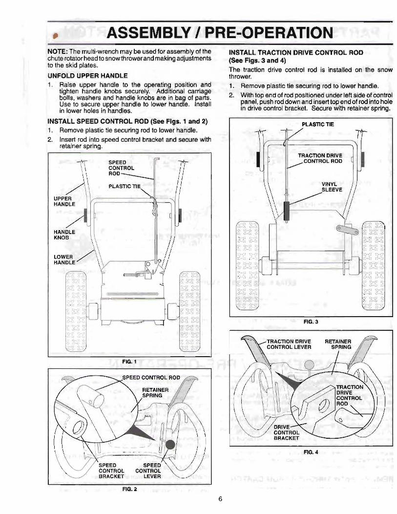
ASSEMBLY 1 PRE-OPERATION NOTE: The multi-wrench may be used for assembly of the chute rotator head to snow thrower and making adjustments to the skid plates.
UNFOLD UPPER HANDLE . Raise upper handle to the operating position and
tighten handle knobs securely. Additional carriage bolts, washers and handle knobs are in bag of parts. Use to secure upper handle to lower handle. Install in lower holes in handles.
INSTALL SPEED CONTROL ROD (See Figs. 1 and 2) 1. Remove plastic tie securing rod to lower handle. 2. Insert rod into speed control bracket and secure witk,
retainer spring.
INSTALL TRACTION DRIVE CONTROL ROD (See Figs. 3 and 4) The traction drive control rod is installed on the snow thrower. 1. Remove plastic tie securing rod to lower handle. 2. With top end of rod positioned under left side of control
panel, push rod down and insert top end of rod into hole in drive control bracket. Secure with retainer spring.
PLASTIC TIE
FIG. 3
FIG. 1
FIG. 4 r
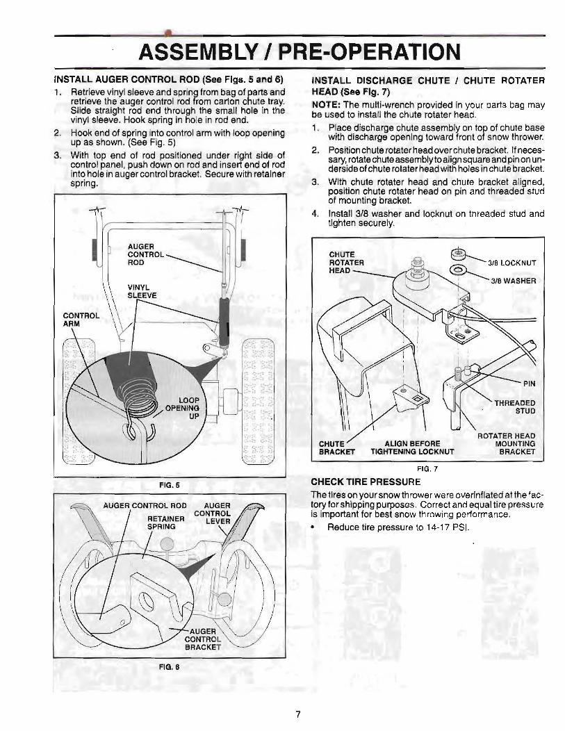
ASSEMBLY / PRE-OPERATION INSTALL AUGER CONTROL ROD (See Figs. 5 and 6) 1. Retrieve vinyl sleeve and spring from bag of parts and
retrieve the auger control rod from carton chute tray. Slide straight rod end through the small hole in the vinyl sleeve. Hook spring in hole in rod end.
2. Hook end of spring into control arm with loop opening up as shown. (See Fig. 5)
3. With top end of rod positioned under right side of control panel, push down on rod and insert end of rod into hole in auger control bracket. Secure with retainer spring.
FIG. 5
INSTALL DISCHARGE CHUTE / CHUTE ROTATER HEAD (See Fig. 7) NOTE: The multi-wrench provided in your parts bag may be used to install the chute rotater head. 1. Place discharge chute assembly on top of chute base
with discharge opening toward front of snow thrower. 2. Position chute rotater head over chute bracket. If neces-
sary, rotatechute assembly to align square and pin on un- dersideof chute rotater head with holes in chute bracket.
3. With chute rotater head and chute bracket aligned, position chute rotater head on pin and threaded stud of mounting bracket.
4. Install 318 washer and locknut on threaded stud and tighten securely.
ROTATER HEAD CHUTE / ALIGN BEFORE MOUNTING BRACKET TIGHTENING LOCKNUT B R A C m
FIG. 7
CHECK TIRE PRESSURE The tires on your snow thrower were overinflated at the fac- tory for shipping purposes. Correct and equal tire pressure is important for best snow throwing performance.
Reduce tire pressure to 14-17 PSI.
FIG. 6
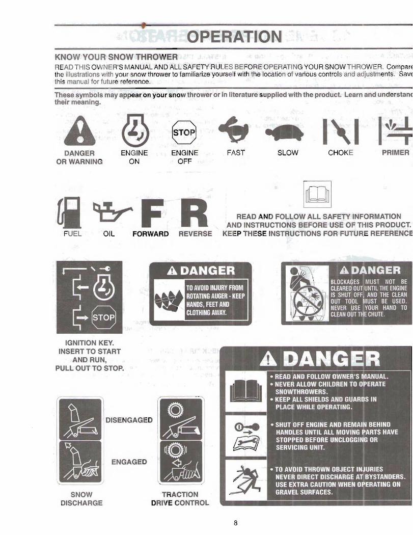
DANGER ENGINE : t a A + j , FA& OR WARNING ON 1!1
-~ .d --... .
SLOW CHOKE PRIMER
: READ AND FOLLOW ALL-SAFETY INFORMATION AND INSTRUCTIONS BEFORE USE OF THIS PRODUCT.
- . OIL FOR WAR^ REVERSE KEEP THESE INSTRUCTIQNS FW FUTURE REFERENCE
I y -
ILOCKAGES !MUST NOT BE :LEARER OUT~NTIL THE ENGINE
IS SHUT OFF^ AND THE CLEAN OUT TOOL MUST BE USED.
IGNITION KEY. INSERT TO START . r :., , 2 51-x.12
* ANDRUN, 3 l ~ t * * , . . , -, .!,-,,I,-
NEVER ALLOW CHILDREN TO OPERATE SNOWTHROWERS. KEEP 411 SHIELDS AND GUAR S IN PLACE WHILE OPERATING. i SHUT OFF ENGINE AND REMAI~ BEHIND HANDLES UNTIL ALL MOVlG ARTS HAVE STOPPED BEFORE UNCLOGGI OR SERVICING UNIT.
It; i L ENGAGED
SNOW DISCHARGE
TRACTION DRIVE CONTROL
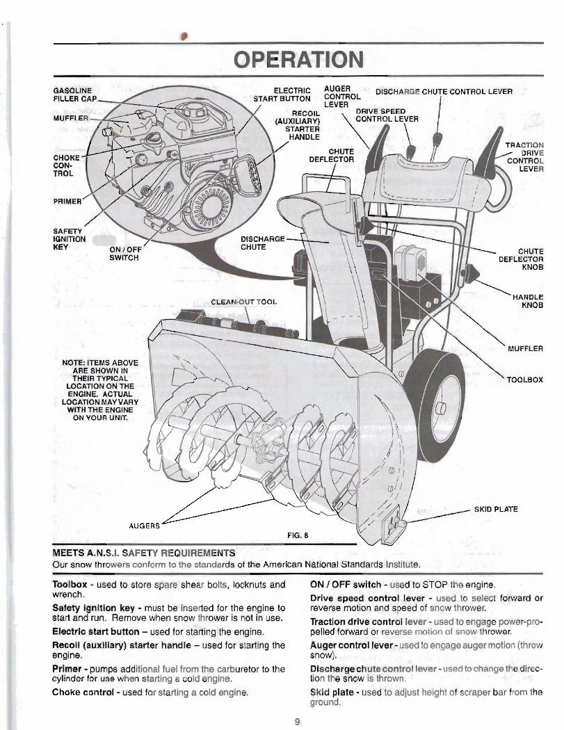
. .I. -A * . Our snow throwers conform to the standards of the American National Standards lnstitrllo
Toolbox - used to store spgle shear bolts, locknuts and ON I OFF swltch - used to STOP the engine. wrench. Drive speed control lever - used to select f d i a td or Safety ignltlon key - must be inserted for the engine to reverse motion and speed of snow thrower.
and when is mactlon drive contmi lever. used to engage power~m- Electric start button - used for stattingsthe engim r n @ ~ t ~ ~ d . w w thrower. Oe~oll (auxiliary) starter handle - used for sta&ng the engine. Primer - pumps additional fuel from the carburetw to the Dlscha cylinder for use when starting a cold engine,
0. * * . Choke control - used for starting a cold engine. Skld plate - used% &just height af sbabrer.bar from tk
ground.

T&xtp&rdon Of my arrtruvthrow~r can -~t~rrsult The DIRECTION In wMch snow is k be thrown is cantrolled in fareign obi- thrown into theeym, which bry tha dischwge ah& control lever. can result in severe eyedamage* Always wear . safety glasses or aye ahiekk while operatin$ your snow tivower or pe*rming any adjust- :ala,
ments or repairs. We recommend standard safely glasses . ;
or a wide viaion safety mask worn over spwtacles.
HOW TO mE YOUR SNOW THROWER Know how to operate all controls before adding fuel W-I attempting to start the engine. I-
STOPPlNOl - < ,= *_
TRACTION DRIVE - 4
. ,{ -&a>-: Release traction drive control I w ~ r to stap the fowal'$ - or reverse movernant of the snow thrower+
AUGER - .
Release the auger c o n t r a l ' M 8 w t w b M g snow&. F; ENQINE - . 4 $ , n
@,',I,
I r Move ON / OFF switch to 'OFP-~WPI, I
a::: Remove (do not turn) Wty ignw h y to p m ~ t unauthorized us$. + , ? Ti,
FIG. 10 .
.t+ . The DT$TANCE that snow is throWn b cantmlfsd by the - NOTE: Never use choke to stop eng!mg ~ $ 1 . 4' position of the chute deflector. Set the deflector low to
4:. &.& throw snow a short distance; set the deflector higher to TO USE CHOKE CONTROL (8- Fig, 9r- '- throw snow farther. The choke control is located m the errgine, Use the ohoh aontrol whenever you am starthg a cold errgsne. Do not u&e to start a warm engine.
r - 2 . - E +* To engage choke, turn knob countcsrcl6bbiee. Slowly
turn knah clook~~La to d l d q w ,
FIG, 9 '!
TO CONTROL SNOW DISCHARGE (&XI Figs. 10 81 11)
WARNING: Snow t h r ~ m have ex-
flm lncludlng startup,
WARNlNG: If tha c f f m h q @h&e or auger beuomecl ge$, 8hWetsglrre fi ~ d ~ U ~ . H m ~ ~ a r t s tostop. UY the clmn-out toal, N T YQUR HANDS, to unclog the chute and#= auger.
, * Tochangethedefl - flector to desired
. . . . . ' _1 . .. . .: - . . . .'.- . +' ., . . ...i; i ' :. '. , 2 < ;$~j,!?.$
. .- , 3 - . "' 'I. _? . - : '
.!!,?*$ - . Y - - ' .,. - . ,. ! /yr :
s .. . ' . 2 :,.&.- ' . ,'. .j. . ;.>:- .$, &-. +'::>&?) ~2
- +,': . -,= , . ' . . , ? . > . ..li . . - 1
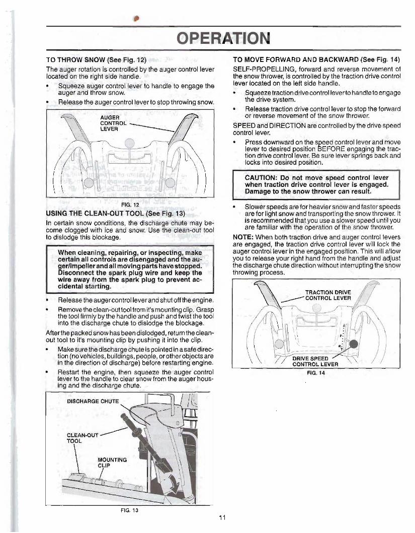
OPERATION TO THROW SNOW (See mg. I*=-)- 31;. i 3
The auger rotation is controlled by the auger eonfrol lever located on the right side handle.
eeze auger control lever to handle to engage the er and throw snow,
eleas ease the auger control leverto stop throwing snow.
WINO TIlE CLEANOUT TOOL (See Flg. 1 3 g : In mWBiM snow mndIrion~, the discharge chute may be- fame GEpggeEcl with &! and snow. Use the clean-out tool to dislodge this blmkage.
Removetheclean-buttool from it'smnting clip. Grasp the tool firmly by the handle and push and twist the tool into the cfkclxGg8 chute to,dlslddge the bbckqp.
~ 8 ~ ~ ~ ~ 6 t f ~ 1 " 1 ~ bexn dl Jadg;ed, Wumthed~n- Out WoI b k'L mounting clip by pushing it Enta the clip.
~ w l r ~ ~ W t W q ~ - c h u t a ' i s in* in asafe die@ tion (nevehwes, buibgBI pmpCkothwabliects are
?ptha dirtsc-th~af dlmharga] beSam m&artlngsngine. IbsWrt &@ einginei then squwe tba auger' wntrol lever U tlwhgndh& clew mew %!;am augpr haws- b g and the dihatgs chute. -
FIG. 13
TO MOVE FORWARD AND BACKWARD (See Flg. 14) SELF-PROPELLING, forward and reverse movement of the snow thrower, is controlled by the traction drive control bver located on the left side handle.
. &queeze traction drive control leverto handle to engage . the drive system.
, 'Release traction drive control lever to stop the forward ar reverse movement of the snow thrower; .. '
ED and DIRECTION are controlled by the drive speed
Press downward on the speed control lever and m ' W lever to desired position BEFORE engaging the trac- tion drive control lever. Be sure lever springs back and locks into desired position.
I
CAUTION: Do not move speed control lever when tractlon drive coritrrrl lever is engaged. Damage to the snow thrower can result.
Slowbr speeds are for heavier snow and faster speeds are for light snow and transporting the snow thrower. It .Is recommended that you use a slower speed until you are familiar with the operation of the snow thrower.
NOTE: When both traction drive and auger control levers are engaged, the traction drive control lever will lock the auger control lever in the engaged position. This will allow you to release your right hand from the handle and adjust the discharge chute dlrwtian without iflsaxrupang the WQW throwing process.
FIG. -
. .. \ , ' ~ . $ *.', . . - t . ' , ; ! . ' ' - T: . i Y ' . . . . , . : \
,. , .
3. : < . / . . , .I : . . . ., '. . +,
. < , , :,. - 1
. . . 1 , ..,<
~.
I ; ' . ..i; , r

T6 AWWT lMPl PLATE@ FEg. 18) 3'-"'. 5 - NOT& Tha wmflch prov4#ad in your p@rt$: bag rn@y be &&aJ ta &]ust the skid phtaw 1-
. . , < d
l ldd plat@ are located an ea66'sid6;o?he ad 'er howlng the c f m m m b@Wmn soraper %, r m d the
Adjust skid plates f4~nly to proper height gturrcant surfam ~~~fldition8, Far removal of onaw in
nsrmttll conditbna, e u ~ h arr a pavd d r l w a y Br sidewalk, plaoe skid plates in the hi hest poeition (bwest scraper P cler%ranoe) to give a 118" ceararrce beweem thr acmpar bar and the ground. Use a middle position if the surface io be cleared is uneven. NOTE: It fs not mcommenderd b oprrate the snow thrower over gravel or rocky surfaces, Qbjectssuch tar gravt~l, rock8
other debris, can easily be pioked up and thrown by the gpeller, which can cause serious pcmonpl.iflljyry, ,. propell)! ~ m w @ or damage to the snow thmwst' m i , _ , ~, - ;
: If @now thrawer must be opmrad ~~cmrgravel ourtaw, .are@ extra oautisn md be surer rrksd ptsatw ara adjuls-tsld
, , @ lowest (hiqhe~t scraper . . elerwanoe) pasition. t, @hut off engine a d *Wail mavinq parts ta $top. P. ; hdjust skid platm by loownln the hex nu$, lhen mov-
Ing skid pl& to deslrad pmlt 9 on. 8e sure both plates me adiusttad ewnty* Tiitgn setcursrly, - . ..
). ') ' b :- . i . ,?
[ LOW POSITION (HUH GROUND CLEARANCE) I P.
PIC% tQ
SCRAPER BAR (See tsrg, In The scraper bar is not adjustable, But is reversible. ARer considerable use it may b~c~mgt worn. When it has warn almost to the edge of the housing, it can be reversed, providing additional service before requiring replammmt. Replace a damaged or warn scraper bar.
BEFORE 8TARTlNG THE EElalJVE CHECK ENE;IiUE QIL LEVEL ($tm Fig. 18) The engine on your snow thrower hu, b&shipp.& horn the Octary, already filled with oil. 1. Check engine oil with snow thwww on level ground. 2. Remove oil fill cap/dipertick Blnd wipe dm, &met
the dipstick and screw tight, wait for a few smmd$, m o v e and read oil lavel. It rgr, add oil until "FUU mark on dipsdek Is m*d. Ds nat ov@flll. Ta change engine oil, sea T O C.HANG€ ENGINE 011" Sn the Maintenance ~srsetton of this manual.
ADD GASOLINE (8- Fig. 16) . . , ;:< : Q:: :
Fill fuel tank to bottom of tank filler neckh- Do not over fill. Use fresh, clean, regular unleaded gasoline wi a minimum of 87 octane. Do not mix oil with gasalln Purchase fuel in quantities that can be used within f days to assure fuel freshness. ,,,. , ,
.% % . &Lbd-- .J'%! ~ ! f * U ; ~ i % 3 ~ - * a WARNINO: Wipe off any spilled oil OK
fuel. Do not store, spill or use gamline near an open flame.
CAUTION: Alcohol blended fuels (celled aso- hol or using ethanol or methanol) can a ?t raot moisture which leads to separation and forma- tion of aclds during stora e. Acidic gas can damage the fuel s stem o an engine whlle in J P storage. To avos engine problems, the fuel system should be emptied before storage of 30 days or Ion er. Empty the gas tank, start .- the englne an ! let it run until the fuel lines and carburetor are empty. Use fresh fuel next. season. Seestorage lnstructlons for additional68 information. Never use engine or carbu~tor, ,~ claraner products in the fuel tank or permanen&@ damage may occur.
M Q J E h ALL ITEMS ARE SHOWN IN THEIR TYPICAL LOCATION ACTUAL LOCATION MAY VARY WITH ENGINE ON YOUR UNIT.
I - - - --- - - - - - - . + ! - ~*
.>, a, . ~ra5a TO STAR7 ENGlM
- .. ..- , ! JC 4
Be sure fuel shut-off valw is in the OPEN position. Your snow thrower engine is equipped with both a 120 Vc A.C. electric starter and a recoil starter, Theelectric start( Is equipped with a three-wire power cord and plug and designed to operate on 120 Volt A.C. household currenj
Be sure your house is a 120 Volt A.C. threewi~ rounded spteim, Lf yau are uncertain, consult
k n s e d - electrician.

WARM @CART r R E W L t 3 T M f 3
kww mhQke tn the 'GFP the primesr.
OEWRR 8-TQPPINQ Run the csn@ne"for a f w minutes to help dry off any mois-
@WIT - ELECTRIC STARTER ture on the engine. " .I <
$.. ItataeH Wt?lty ignition key @kid ta recoil start cord into IF RE~~XJIL STAR^ WA;S ~ Q = N
R ii 'OPY 'lot * me key. 11 the recoil ahulsr RBs Rmen and will not turn the engine, '
t e e&ra sr%f@ty ignition k@y in a mfe place, pmceed es bIlows: ' &
L Pieroe ON / OFF swftch in "ONn posiiian. 1. Grasp the recoil starker handle qnsl gd~wly pull as muoh
S Rota& choke control to "FULL" position. rope out of the starter as wwiblei. 4 G ? n m the pawer cord ta the engine. 5. ~lq,lh.'&hwend dlh, power cord into a thnbhole , g t % m t ZO &# A.C, #QTEt Po net me primer h e n staQg gngine with thrs erlecttb @tartar.
8. D i w n m t the pow^ card Qrdm th@ r WR from t b Emglina.
~u&the o he to wMn u for a few minutes. & HI opt tbwd~p "B uII pwer untl It ha& remherd norr& oprat~ Rg t o m p ~ ~ .
P WARM START - ELECTRIC STARER FollDW $he st@pe abauja, ka~ping the choke cop1tml in the "OFF" gosition, COW &ART FEGQl L STARTER I. Inaart s-%If&& igir1Itaon key to r w i l start Dord into
I nitinn slot unlit Midcs. O NOT turn th@M@. AEtp R b t e e~trafsclfity ignirlan b y in a FF w b h In 'ON" pi t ion. m t m l to "FUU patinn.
4. Pursh .tkQ liRn@r four 4) timm l thr ttmpembre is 6 blow I p f o r two 12) m u ntanprwstumta between 1 5' and !if0 F. If t b ~ r a t u r a F8 a b m 60aE primha is riot rrmmry.
NOTE Q&$;ptfmin-g'may mum flmdhg, pre\renBn@ the enghe from aath'lg If you do fbod t b engin&, wait r ft?w miinurn hbre.&mmg &I &at and DCI NOT push the Drirner. b F%iI wl starhw handls quicMy. Do not allow $tartw
roper ta snap tmk. 6$ % When theenginestwts, W~~the reco i3 ~st@er h~ndls : ansl'slawly-me the choke control to the "(CZFF pmb
-tian, AllwT176m * crl trx warm up for a few minutehp. Enghet will not d !$I pawer until it has n&hed normal opera- ing tcamgwatun.
2. ~ i l easa the rerwrv starter.handie and let it snap beck klgainst the .%tartar.
If the(swi~(~i~ Mill hib ta start, repeat me a b w st.eps or wr th8:elmtri~ $tarter.
SNOW mmwi~lcz nps AJwaw. operate the sngWthmw@f With the engine at full thrc%lo. Full throttle offers bad perrfomanlc9.
h3Wsnow. ummo th ro , to adjust speed.
It is w i e s and m r e efficient to remove snow imme- &ally a h r iZ 1"alls. th61 bwt time t~ re~av~~sntrw k the eiarly morning. At this tlme t& anow IS usudiljly dry and ha& nat been ex- p w d to ffier dimct sun and warnu'ng bmprsmtures. SiigS1tIy overlap each succwsh path ta cs;nBufe dl snow will be removwl,
Ailjust the skid plates to m &r h&i ht for mrr&ntsnow w~dttiono. TO &SST d~ PLATE@ in this d o n of this manual.
- par extremely heavy srlaw, revduQe the, width of snow lwt'mxd by cm~Mappimg ~ ~ ( I I V ~ Q ~ B P . path and moving sJuwly.
* engtfio rlm and clear of snow during use. This wiU Rip air fib* and exteM engine life. Afbr~nawthmMng 15 cbmpWd,Jl~w angina to run for a few minuted to melt snow md, off. Me engine. &m the entire snow thrcrwr th@roughly after each use and wipe4 dry so it is ready far neq use.
WARNSPIIQ: Do n d aperate snow
a thraww kfwmth&rmndiBarm Impair vls- Iblllty. Throwlng snow during ;a-htmvy, winds e~ow8trom a n Wind yau and be hazardmus t~ the mj& opemtl~n of the enow thlawtar.
- -
FILL IN DATES
GENERAL REEOMIVIZW DATIONS "'"" . ti ', ,
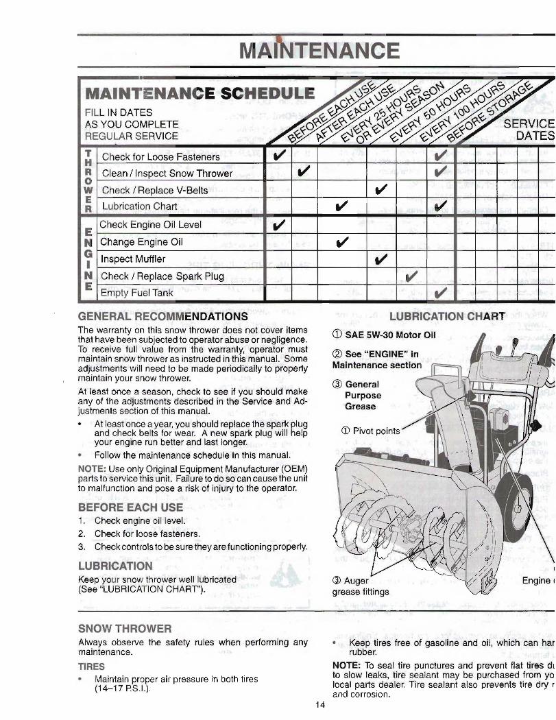
The warranty on this snow thrower does not cover items that have been subjected to o erator abuse or negligence. To receive full value from 8 e warranty, operator must maintain snow thrower as instructed in this manual. Some adjustments will need to be made periodically to properly maintain your snow thrower. 1 . I
At least once a season, check to s& i( you'dh.$u~d make any of the adjuetments descriied in the Senrice and Ad- justment@ ~ s x l of this manwal.. ,.: ! ,?; .
At least once a year, you do&! replace the +rk lug
your engine run better and last longer. I: and check belts for wear. A new spark plug wilt elp
Follow the maintenance schedule 'in this manual. NOTE: Use only Original Equipment Manufacturer (OEM) parts to sewice this unit. Failure to do St5 can muse the unit todfuncticm and pmgt a rkk Qf injury to the opeatar.
'BJ t, 1 " . ,%: L. 1 +$,*
USE. .- if- A * 1. Check engine OH I m B 2. Check for loose fastek&rs. .
.I YI , * . .i J r . ', . -
,I i
. , 1.. ;I
SNOW THROWER . . ,.I'
Always observe the &&y rule@ JprformiB$j any *i .Keep tires frw af maintenance. .,I :a rubber. "I{ ,:T, df I
> .
TIRES ; 8 NOTE: To seal fire punctures and prevent flat tires dr * Maintain pro er air prmisure in both tlrm to slow leaks, tire sealant may be purchased from yo
(1 4-1 7 RS.I!~'. local parts deafer. Tire sealant also prevents tire dry r and corrosion.

. , .+ = - - .. ?
BELTS 1 ._ & - 3. - :, .%Ik,<.. * - . - $0 CHANGE ENGINE OIL Checkbelts for deterioration and wear after every 50 hours Determine temperature range an'licipated before ned oil of operation and replace if necessary. The belts are not change, All oil must meet API service classification SG-SL. adjustable. Replace belts if they begin to slip from wear. Be sure snow thrower is on suhce. (See Y O REMOVE BELT COVER".in the Service and Adjustments section of this manual)r Oil will drain more freely when warm
* - The belts on your snow thrower are of special construction ' Catch oil in a suitable ~Qt~tainer. 2
and should be replaced by original equipment manufacturer NOTE: The left side wheel may be removed f&$ !$now (OEM) belts available from your nearest dealer. Using other thrower for ~asier accew to the oil drain plug and placeiz than OEM belts can cause persona or damage to ment of a suitable container, The unit tllted, resting on the the snow thfmar. . - < . frame with the left wheel removed, will help drain any oil
, I + r trapped inside the engine. (See "TO REMOVE WHEELS* in the Service and Adjustments section of this manual). 1. Remove safety ignition key and discmned spark plug
wire from spark plug and place wire where it cannot come in contact with plug.
2. Clean area around drain p l a n El3 #"lQrease. 3. Remove drain plug and drain oil in a suitable container.
.. 4. Install drain plug and tighten securely.
snow 5. Wipe off any spillad oil from snow thrower and engine. on $. Install left wheel (if removed for draining oil). Be sure to
install klick in into roper hole in wheel axle (See "TO -REMOVE HEEL ! " in thqfienrlce and Adjustments sectidn of this manual).
7. Remove oil fill cap/dipstick. ~6 to enter the enginer --
8. Reff ll engine withWIl9+1mugh" st1 wkk 'cW; ,Four slawly. Do not overfill. For ap roximate capacity see "PRODUCT sPEGIFIcATIoN~~ section of thls manual.
ENGINE on oil fill cap/elipstick for chwking level. See engine manual. stick cap Cs ti htened securely for accurate
oil at "FU C' line on dipstick. LUBRICATION ' '
I t@,'Wiie off any spilled oil. a
Use only high quality de"tbr~eW dl rated W ~ ~ A P I se9%& , , . , . i '
_,I- .. classification SG-SL. Select the oil's SAE viscosity grade . >
according to your expected operating temperature. Insped dd replace corroded' .& d fire hazard andor damaga
, . SPARK PLUGi: Replace spark plu~dthe bagh-ming of each seas~n or aRer every 100 hours of operation, whichey~r ac~urs first. Spark plug type and gap setting are show [n the "PRODUCT SPECIFICATIONS" section of this mnuai.
CLEANING ' , . *
IMPORTANT For best perf~rm&tcrl;- !keep snow thrower housing free of any dirt or trash. Clean She outside of your snow thrower after each use.
NOTE Alfhowgh multi-viscosity oils (5W30, 1 OW30 etc.) improve shfftrrg in cold weather, these multi-viscosity oils will result in irrereased oil consumption when used above 32°F. Che* yausmgine oil level more frequently to avoid possWe lengiw damage from running law on oil. Change the ujt ef€er every 25 hours of operation or at least Keep finished surfaces/wheelafree of gasoline, oil, etc.
once a year if the smw thrower is not used for 25 hours We do not tw~mhend Udhg a gar- to dean in one year. your snow thrower unless the electrical system, muffler
and carburetor are covered to keep water out. Water Check thecmkcaseoil level beforestarthgthe engine and h engine can result in shortened engin%-li%e, after each ffve (5) hours of continuous use. Tighten oil fill $,
Cap I dipstick securely each time you check ttre oii tevd. - -
-, . _ a t- : . A .
. WARNING: Disconnect spark plug wke from sparkplug and placewire H e r e it cannot came In contact with plug.

SERVICE AND AWUSTMENTS To replace the capscrewlshear bolts: . % WARNlNGi: To avoid serious Injury, before :-:I !
performing any mrvtce or adjustmsnts: p 3- .t 1. Disengage all controls and move throffle cbnirol . , . STOP position. Wait for all moving parts to stop.
1. Be sure the OM swltch Is tn thew OFF position. AIP Remove safety ignition key and disconnect spark p
. wire from spark plug. Place wire where it cannot co A 2. Remove safety Ignitl~R%&y:~. o'r 'V in contact with spark plug. - - . ;a.t,ir,. yc.
1 1 3. Make sure the augers and all msvin$ . , parts have completely stopped. !
I 4. Disconnect spark plug wire from'; ;' - I spark plug and place wire where #,
" 1 . cannot come In contact with plug. , $'-
SNOWTHROWER -- . >,+~*.--~,a i TO ADJUST SNOW THRO &&m : 4 .
fr See T O ADJUST SKID PLATES" and "SCRAPE?$.BAR" in the Operation section of this manual. ..
. , , , r C a CHUTE DEFLECTOR The chute deflector, attached to the top of the discharge chute, is provided to direct discharging snow away from the operator. If the deflector becomes damaged, it should
. , be replaced.
WARNING: To avold serlous tnju
the deflector removed or damaged. 3 never operate your snow thrower wit
.. To change direction and/ordistancssnow b discharge& - -see T O CONTROL SNOW DISCHARGE" in the Op-
eration section of this manual.
SHEAR BOLTS (See Fig. 17) ,
AUGER SHEAR BOLTS 4 ' . , .
Both right and left-hand augers are secured to the auger shaft with aspacer, shear bolt and hex nut. Should aforeign object or ice become lodged in the augers, the shear bolts are designed to break, preventing damage to any other components. If one or both augers do not turn when auger control lever is engaged, check to see if one or both of the bolts have sheared. To replace the shear bolts: 1. Disengage all controls and move throttle control ta
STOP position. Wait for all moving parts to stop.. *
2. Remove safety i nition key and disconnect spark plu i wire from spark p 9 ug. Place wire where it cannot coma in contact with spark plug.
3. Align hole in auger hub with hole in auger shaft andl ' install a new 1/4-20 x 2" shear bolt. Install 1/4-20 .
- lock nut and tighten securely.
CAUTION: Do not substitute. Use only original equipment shear bolts as supplied with your snaw thrower. -
4. Insert safety ignition key and reconnectspark plug wtm to spark plug.
l M P m S H E A R B O L m dig '+'*; ' % - . i
The impeller is secured to the impdkr ahan with two (2) capscrewiehear Wts 4 hex nub. S h W a foreign object or ice become lodged In the impeller, the capscrews are designed to bxeak, preventing damage to any other com- ponents. If impeller does not turn when auger control lever is engaged, check to see if the capscrews have sheared. 1'6
,.-$i-: Align holes in im eller hub ~ + K J & S f i ~ - and install two (2y new 1/4-20 x 1
bolts. Install 1/4-20 locknuts am?
CAUTION: Do not substitute. Use only ortginal equipment capscfewlshear bolts as supplied wRh your snow thrower.
4. In%erY~a1&yignNbn key and reaxmeet spark plug v to spark plug. ,.-.
f .I . .; : -- c:f
@.@crews securing belt cowl - - -< .
2. Remove belt - A = , ' .+ *
3. Replace belt cover by installing cover and screws t tighten securely. -w$
- '*
RO. 18

SERVKE AND-N$JUSTMENTS
, WARNING: Belt replacement r ulres , separation of the snow throwe%hile
:'I 1 separating theauger houslng from the frame assembly, It Is important that
1 an assistant stand in the operating e asMan m d hold the snow thrower
. andlea. Serious personal Injury andl 4 I. *,- , or damage to the unit muld occur if
.) I the snow thrower should fall during the belt changing process.
F R A M ~ Aum HOUStffi
- , + ? '
4
TO REPLACE BELTS (See Fig. 19) :fie' T . , d : i i ~ t 8. RELIEVE TENSION ON TRACTION DRIVE BELT The ayger and traction drive belts are not adjustable. If th$ IDLER and remove traction drive belt from around beltsate damaged or begin to slip from wear, they shoukl pulleys. Ire replaoed. I1 is recommended that the belt(s) be replmdd HINT Insert a 318" drive ratchet (in the "ON p o ~ i t i o n ) ~ ~ bh a $ears service dentreldepartment. ' "!I the quare hole in idler arm and rotate ratchet clocWi NOTE: It is recommended that both the auger and traction raltevs . 1
drive belt be replaced at the same time. 8. With tension relieved bn Mer, ih€lgll ne~Wac~kytWbe The V-belts on yoursnow throwerareof spet3Bl~truction belt around pulleys and inside belt keepers. and should be replaced by original equipment manufacturer 10, Install clutch rod in wing plate; secure with hairpin. (OEM) belts available from Your nearest Seat'S service 1 1. Place au erbelt around and inside the groove of auger centreldepartment. Using other than OEM beltscan cause pulley on y. gersonal injury or damage to the snow thrower.
7 12. While your asl5-iant tslowly raises handles to rejoin
the au er housing and fmmts assbmbly, pull up on the au er elt and squeeza rides to @her above pulley so % e12 is fully set~bd in groove o r pulley.
13. Move idler arm so itgoes not hit irflprller pmey as you! bring snow thrwer completely together and check carefully for praper routing of belts. If auger belt has becomedislo ed from the pulleyfb catching the idler, $, \ arm bracket w Ele b'Pinping snBw t rower together),; separate the s n w thrower and repeat step 12. Beit must be fully seated in pullw groove %hen bringiags
. the snow thrower together.
1. REMOVE GASOLINE FROM FUEL TANK - Drain gasoline from fuel tank into a suitable container, out- doors, away from fire or flame. Wipe up any spilled gasoline.
8. , REMOVE DISCHARGE CHUTE - Loosen locknd~ securing chute rotator head to mounting bracket only enough to allow chute rotator head to be raised and discharge chute to be removed from snow thrower.
3. REMOVE BELT COVER - See "TO REMOVE BELT COVER" in this section of this manual.
4. REMOVE ENGINE PULLEY - Remove bolt, flat washer securing pulley to engine crankshaft. Remove outside
; (auger) pulley only from crankshaft. 5. SEPARATE SNOW THROWER - With your assistant
standing in the operating position holding the handles, remove the two (2) bolts holding the auger housing and frame together.
WARNING: As the last bolt is removed, our assistant carefully lower the
down to the ground. . '6. REMOVE HAIRPIN FROM CLUTCH ROD and re-
move clutch rod from swing plate. Tip swing plate forward.
7. REMOVE AUGER BELT from mud
m FIG 19
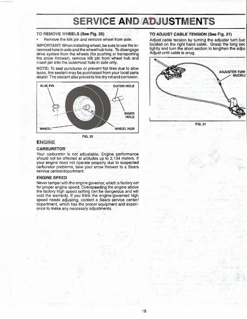
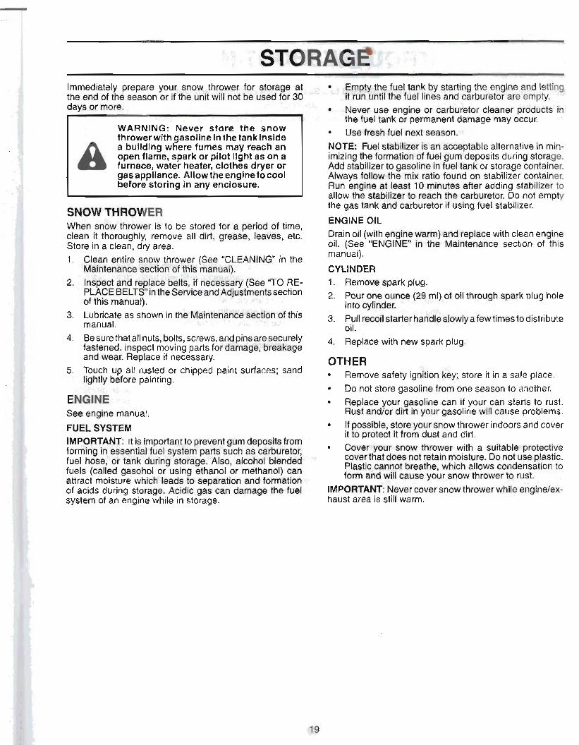
SERVICE AND AbJUSTllTINTS . , . . -4q .& TO REMOVE WHEELS (Sm Fig. 29&& L',,. ic 3fi TO ADJUST CABLE TENSION Cfbe Fig. 21) I * J S ~
Remove the klik pin and remove wheel from axle. . A q d caMs tension by turning the adjuster turn hue IMPORT&NT When installing wheel, be sure to use the Fa- baa^ on the dmt hand cahl@. QrW Ihe long nermost hole in axleand the wheel hub hole. To disengage *gh* and turn the short -On to lengthen drive system from the wheels (for pushing artramporting Adiustunt[l cable is snug. the snow thrower), remove klik pin from wheel hub and insert pin into the outermost hole in axle only. NOTE: To seal punctures or prevent flat tiree due to stow leaks, tire sealant may be purchased from your local parts dealer. Tire sealant also prevents tire dry rot and corrosion.
KLlk PEN - W'FeR HOLE
I
i HOLE . - (; 3-
3
wHeeL r -.i;' "" '"' ' '
, WHEELHUB
- . AG.20 . - ' 1 - 1 1 , :q : .
ENGINE t r, ., ,, ;. . + br- w-. I
CARBURETOR . '" ' . + , , . . , -
Your carburetor is not adjustabie. Engine performance should not be affected at altitudes up to 2,134 meters. If your engine does not operate properly due to suspected carburetor problems, take your snow throwm to a Sears servlce center/department.
.. el ' ENGlNE SPEED. I . .
I . . ~ -. 2 %
Never tamper with the engine governor, which is factory set for proper engine speed. Overspeedlng the engine above the factory high speed setting can be dangerous and will void the warranty. If you think the engine-governed high speed needs adjudng, contad a Sears service center1 department, which has the proper equipment and experi- ence to make any necessaty adiustments.
Immedlatety prepare your snow thrower for storage at Empty the fuel tdnk by starting the engine and le$C: the end of the season or if the unit will not be used for 30 it run Clntil the fuel lines and carburetor are empb ' days or more.
,.. . . 2 + q v - j ,
- , Never uee engimior barbuntor cleaner produ&hl ' - ltm fuel tank or permanent damage may occur. .. 1-7 WARNING: Never store the snow thrower with gasoline In the tank inside Use fresh fuel next seasorr:e
a a building where fumee may reach an &T€: Fuel stabtlizer is an acceptable alternative in m b open flame, spark or pllot light as on a imiting the formation of fuel gum deposits during storage. furnace, water heater, clothes dryer or Add stabilizer to gasoline in fusl tank or storage container. gas appliance. Allowtheengine to cool Always follaw the mix ratio found on stabilizer container. before storing in any enclosure. Run engine at least 10 minutes after adding stabilizer to
I allow the stabilizer to reach the carburetor. Do not empty the gas tank and carburetor if using fuel stabilizer.
ENGINE OIL . - Drain oil (with engine warm) and replace with clean Bngine
oil. (See "ENGINE. in4hel ,Maintenance section of this manual). .(I . -
4 - CYLINDER X . . _
4.
I 1. Remove spark plug. I t
, 2. Pour one ounce (29 ml)< of bil through spark plug hob into cylinder. "' , ,
uc i?. - 3: Pull recoil stad& handieslowly 8few times todistribute ,.* L!- ' ! ' , t C L --**I :jd
,.:I UII.
: 4. Replap y j ~ , ~ v y s p a r k plug. t"
OT'HER ' 6 # 7 , . .;is
Remove s a r i ignltlon'f&y'; stdie it in a $& $a+ >: st.. > I ' , , , ' , - , , DO not store gasoline from one ssason to another.
ENGINE ; - - - - I . I . 1- - - . I Replace our gasoline can if your cbn starts to rust.
See engine manudl;~ : . ... . ,..&, ... ... I . j:.f. Rust an dY or dirt in your gasoline will cause problems.
FUEL SYSTEM If possible, storeyour snow thrower indoors and cover it to protect it from dust and dirt.
IMPORTANT: It is important to prevent gum deposits from . ,. Cover your snow thrower with a suitable pmtectiw forming in essential fuel system parts such as carburetor fuel hose, or tank during storage, AISO, alcohol blende&l- '1 1
cover that does not retain moisture. DO not use plastia fuels (called gasohol or using ethanol or methanol) can , Plastic cannot breathe, which allows condensation to attract moisture which leads to separation and formatior7 form and will cause your snow thrower to rust: of acids during storage. Acidic gas can damage the fuel. . ., IMPORTANT: Never cover snow thrower whilesagikexC system of an engine while in storage, haust area is still warm.
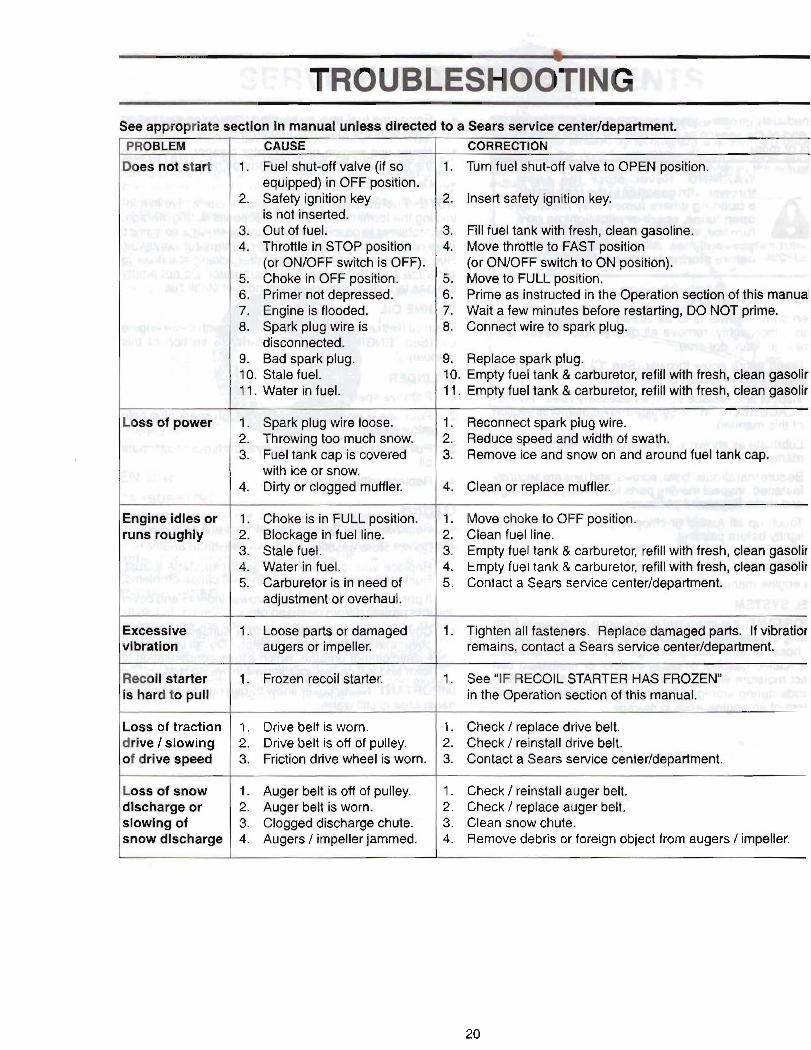
See aaPrQ)~tWe section In manual unless directed to a SmiYrr &milea m f l m a n t . - CAUSE C0RRE;CPION
1. Fuel shut-off valve (if so 1. Turn fuel shut-off valve to OPEN position. equipped) in OFF p i t ion.
2. Safety ignition key 2. Insert safety mition key. is not inserted.
3. Out of fuel. 3, Fill fuel tank with fv;mh, dam gmdine. 4. Throttle in STOP position 4. Move thrmle to PAST p68Mon
(or ONDFF switch is OFF). (or ONIOFF switch ta ON pmltion). 5. Choke in OFF positi~n. 5. Move to FULL position. 6. Primer not depressed. 6. Prime as instructed in the Operation s@Im d this maud 7. Engine is flooded. 7. Wait a few minutes before restar%'ng, DO NOT prime, 8. Spark plug wire is 8. Connect wire to spark plug.
disconneded, 9. Bad spark plug. 9. Replace spark plug. 10. Stale fuel. 10. Empty fuel tank & carburetor, refill with fresh, clem @boEis 11. Water in fuel. 11. Empty fuel tank & carburetor, refill with fresh, clean gawlir
Loss of power 1. Spark plug wire loose. 2. Throwing too much snow. 3. Fuel tank cap is covered
with ice or snow. 4. Dirty or dogged muffler.
1. Reconnect spark plug wire. 2. Reduce speed and width of swath. 3. Remove ice and snow on and around fuel tank cap.
1 4. Clean or replace muffler.
Engine idles or runs roughly
1. Choke is in FULL position. 2. Blockage in fuel Itne. 3. Stale fuel. 4. Water in fuel. 5. Carburetor is in need of
adjustment ~7 omrhaul.
1. Move choke to OFF position. 2. Clean fuel line. 3. Empty fuel tank & carburetor, refill wlth fresh, clean gasdr 4. Empty fuel tank & carburetor, refill with freeh, clean g$$oIi~ 5. Contact a Sears service centerldepartment.
ExtxmsIve 1. Lome parkor damaged 1. Tighten all fasteners. Replace damagd parts. If vibratiof vlbtation augers crr impeller. remains, contact a Sears service center/department.
Recoil starter
Loss of traction drlve / slowing of drive speed
1. Frozen recoil starter. 1. See "IF RECOIL STARTER HAS FROZENn in the Opefation section of Ws manual.
1. Drive belt is worn. 1. Check / replace drive belt. 2. Drive belt is off of pulley. 2. Check / reinstall drive belt. 3. Friction drive wheel is worn. 3. Contact a Sears service center/department.
Auger belt is off of pulley. 1. Check / reinstall auger belt. Auger belt is worn. 2. Check / replace auger belt.
3. Clogged discharge chute. 3. Clean snow chute. Augers / impeller jammed. 4. Remove debris or foreign object from augers / impeller.
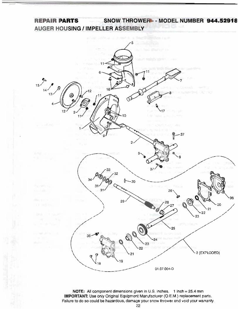
NOTE All component dimensions given in U.S. inches. 1 inch = 25.4 mm . IMPORTANT! Use only Original Equipment Manufacturer (O.E.M.) replacement parts.
Fallurn to do so could be hazardous, damage your snow thrower and void your warranty. 22
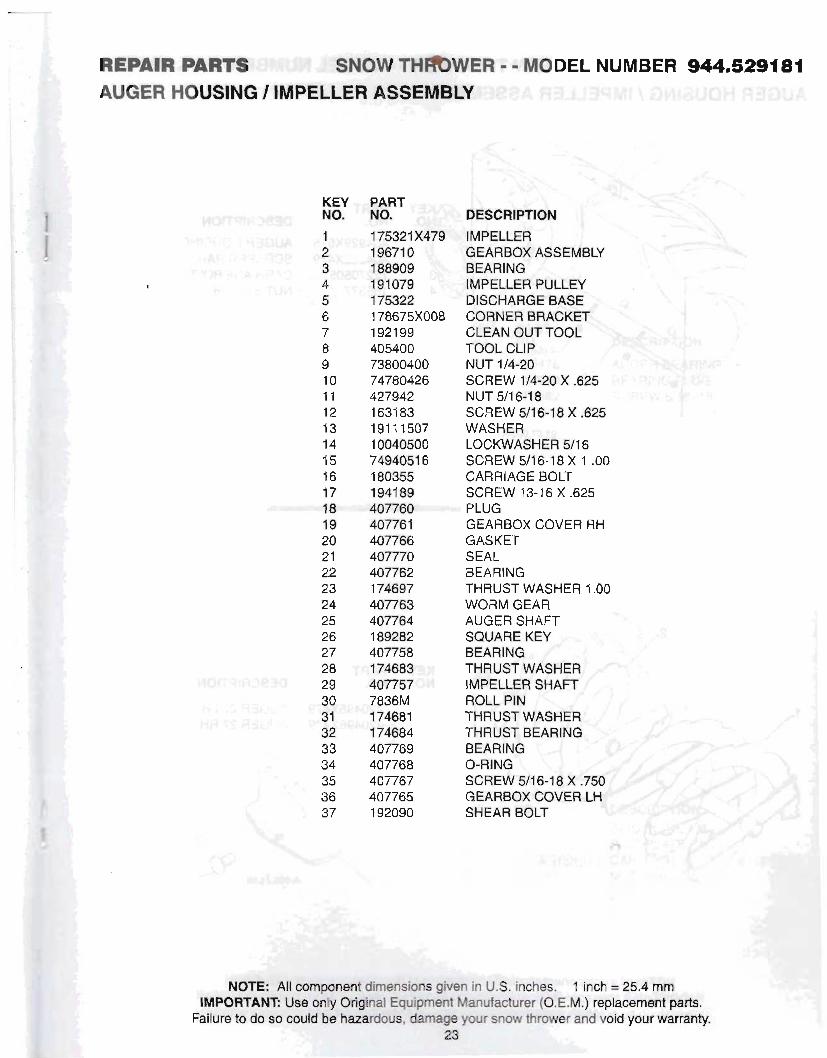
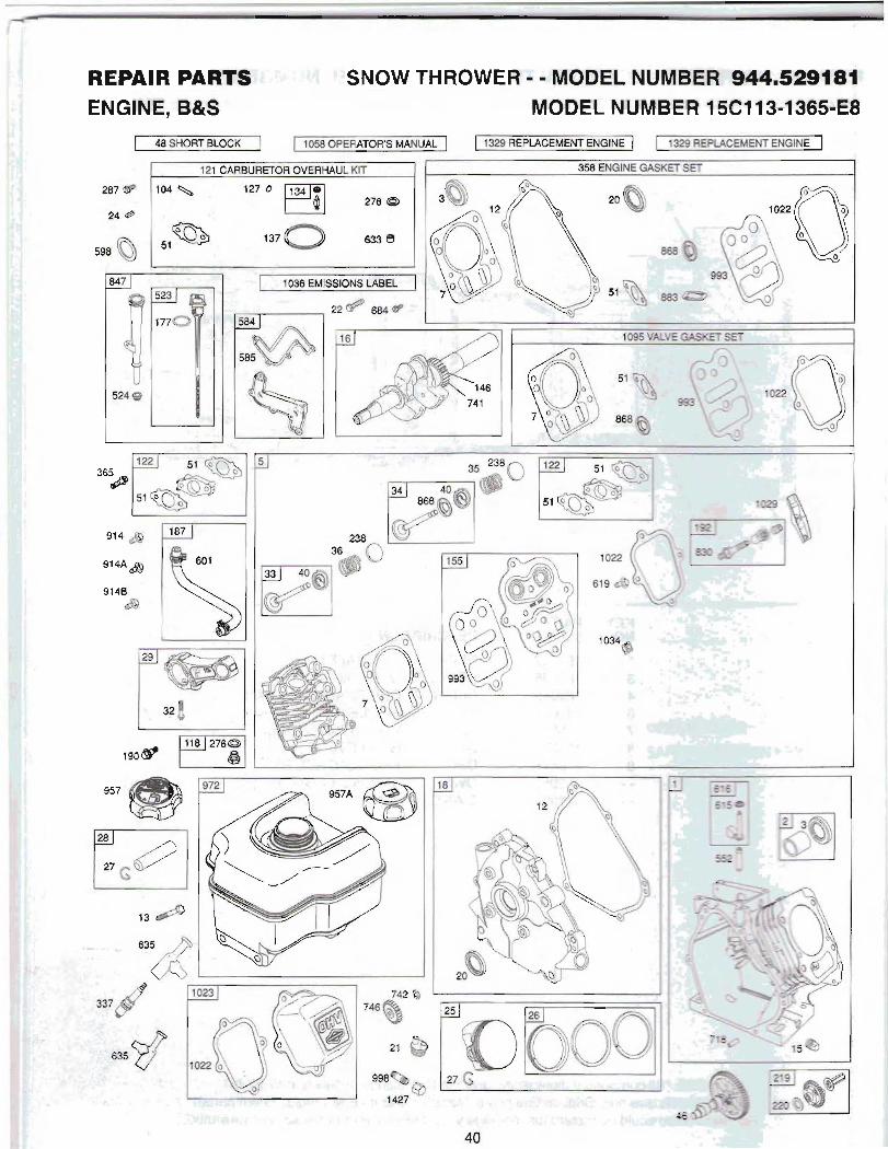
REPAIR PAR 4 TWWER - - MODEL NUMBER 944.J2918i AUGER HOUSING I IMPELLER ASSEMBLY WA R L U ~ M \ WWOH (IIDUA
KEY NO.
PART ,_
NO. ,fi. 1 75321 X479 IMPELLER 196710 GEARBOX ASSEMBLY 188909 BEARING 191 079 IMPELLER PULLEY 175322 DISCHARGE BASE +, A
178675x008 CORNER BRACKET,. 1921 99 CLEAN OUT TOOL 405400 TOOL CLIP i 73800400 NUT 1/4-20 74780426 SCREW 1/4-20 X .625 I .
427942 NUT 5/16-18 XJIf:':" / 1 631 83 SCREW 511 6-1 8 X 325 19111507 WASHER 10040500 LOCKWASHER 511 6 d 7494051 6 SCREW 5/16-18 X 1 -00 180355 CARRIAGE BOLT 1941 89 SCREW 13-16 X .623 407760 PLUG 40776 1 GEARBOX COVER RH
-1 3
407766 GASKET -4- ' J i ,I
407770 SEAL 407762 BEARING 174697 THRUST WASHER 1 .OO 407763 WORM GEAR 407764 AUGER SHAFT 189282 SQUARE KEY 40775P BEARING 174681 ( THRUST WASHER H?? 40775; 1 IMPELLER SHAFT 7836M ROLL PIN 174681 THRUST WASHE 1 74684 THRUST BEARIN 407769 BEARING L 407768 407767 407765 GEARBOX COVER LH 192090 SHEAR BOLT
i- MODEL NUMBER 944.5291 . ..V ..
; '-.:'F:'F.-#' . :- y4,;: ,;; <: , &.!: cy..3, , .~,,.a.l:i,.:+.
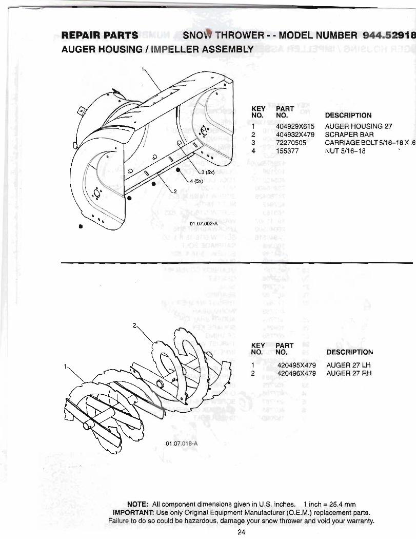
DESCRIPTION
404929x61 5 AUGER HOUSING 27 404932x479 SCRAPER BAR
DESCRIPTION .
AUQER HOUSING 1 IMPELLER ASSEMBLY
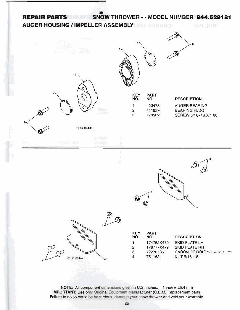
KEY PART NO. NO.
1 420478 AUGER BEARING 2 41 1939 BEARING PLUG 3 179582 SCREW 511 6-1 8 X 1 .OO
KEY PART NO. NO. DESCRIPTION
1 74762x479 SKlD PLATE LH 178777x479 SKlD PLATE RH 72270506 CARRIAGE BOLT 511 6-1 8 X .75 751 153 NUT 511 6-1 8
PART Lx . . NO. - DESCRIPTION i. :
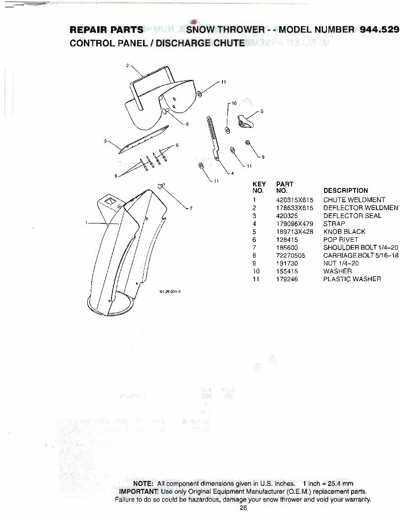
CHUTE WELDMENT DEFLECTOR WELDMEN' DEFLECTOR SEAL* . STRAP KNOB BLACK POP RIVET W W D E R BOLT 1 /4-20 CARRIAGE BOLT 511 6-1 8 NUT 1/4-20 WASHER PLASTIC WASHER

RERMR PaPIlS THW"6W'ER - - MCMEL NUMBER CONTROL PANEL 1 DISCHAROE CHUTE
f 2
KEY PART NQ,. NO. . - DEmwPn?!4., . - - . ,- 1 LEVEWCABLE R O T A M AS$EM8LY 2 1 '75U1010 SCREW 1 0-24 X ,625 *3 420678 ROTATOR HEAD *4 420677 ROTATOR PIVOT BRACKET *5 420675 PULLEY PIVOT *6 428273 CABLE ASSEMBLY ADJUSrABCE *7 42831 0 CABLE ASSEMBLY HEAT SHIELD
NOTES: 4
1 I
1. ITEMS INDICATED WITH AW * ARE Ll!3FBD A$ FSFEFlEMCE F6'&3 @I#'WICE PARTS ONLY. wTr4lxx3a
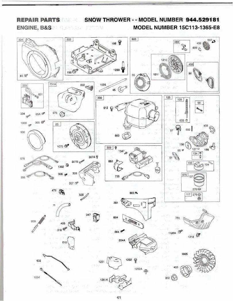
RLRAIR R L M 9%4i!:' - SNOW THROWER - - MODEL NUMBER 0 4 4 6 8 9 4 . . . *. HANDLES 3 = , ? ,7 1 .3;*5- 8 , ' :. f ,. r r ? 6 . 8% .-. - ,: , : .Ll
p*RT -,--
NOi NO* 1 41 97W4T 9
.-
, . , . . , .
:, ;- 25- - . . - - -' ,:< ?!" . -- , __-+ , ..-- . ' I
. . .--. . :i _. -- _ . ' * ' . %.,
, , . . ,. . . . - I' . .
.. . :;. . . .
- . . - . ':,
. -.I r.-sc.xmdicSA: a IU.
.. ., ZI ,,I . ? : . . , - - , 6 , SF.. . . -1
',a. . .I. "' ' . .+=-..? . i r
,'v 9; .,* ,, .; ,:. . . $.;;!- . . . . * " ; -. ,
.. -.-*. 7, ' ' C . r .,.? i h 7% c ' . .. .
,. . -
T.,,.,. ' . .;<: i .;,
. -2 7 ,,; - . 3 . , . . . ': . b . ! < , - , , , .. .
. _ , ..
,.,:.;.- , - :$ - -KEY PAR% . . - ,
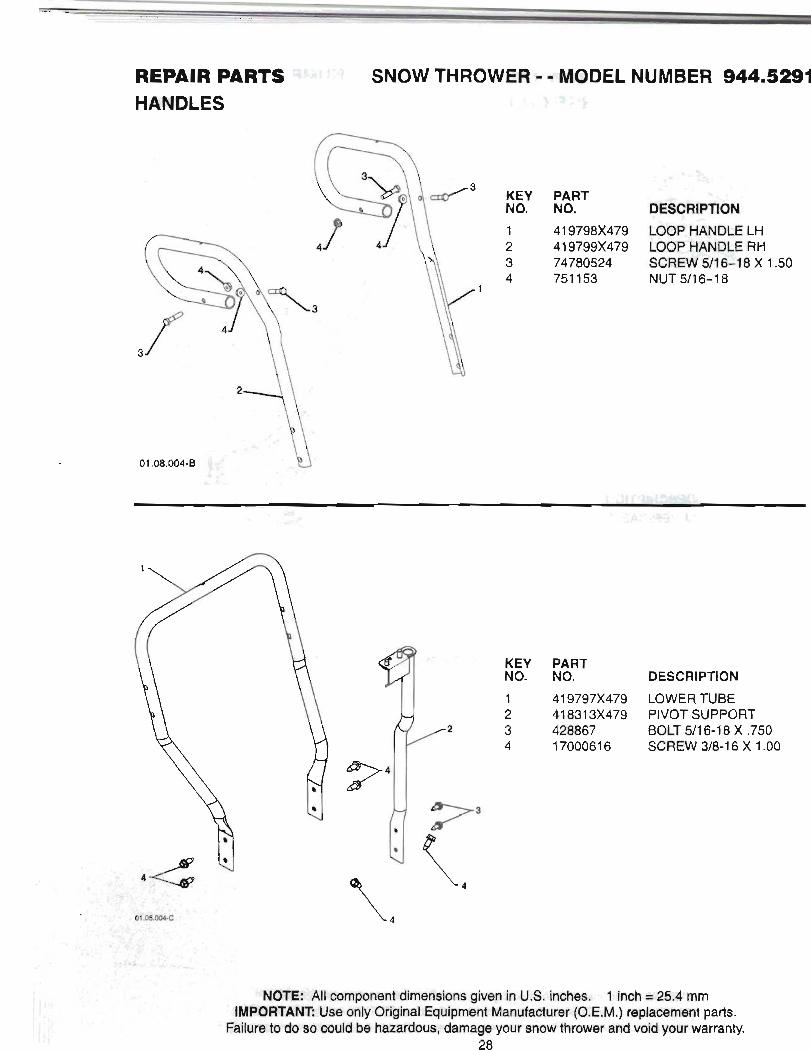
NO. NO. DESCRIPTION 41 9797x479 LOWER TUBE 41 831 3x479 PIVOT SUPPORT
BOLT 511 6-1 8 X ,750 1700061 6 SCREW 318-1 6 X 1.00
. .
, .
REPAIR PART Jl SNOW THROWER ; "MODEL NUMB-.S~~~'P
HANDLES 231QDiiBt.k
\-I4
I
12
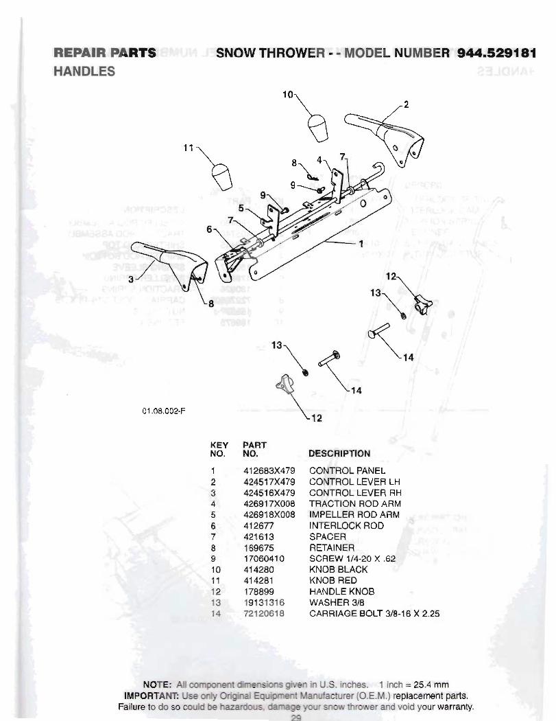
KEY PART NO. NO. DESCRIPTION
CONTROL PANEL' CONTROL LEVER LH CONTROL LEVER Rt TRACTION ROD ARM IMPELLER ROD ARM INTERLOCK ROD SPACER RETAINER SCREW 1/4-20 X .a KNOB BLACK KNOB RED HANDLE KNOB WASHER 318 CARRIAGE BOLT 3/8-16 X 2.25

d
MWAlR CMTS ! C w : ! i,'. SNOW THROWER - - MOML NUMBER W4.5PBlI HANDLES
: 3 , ID.
REPMW PARTS HANDLES
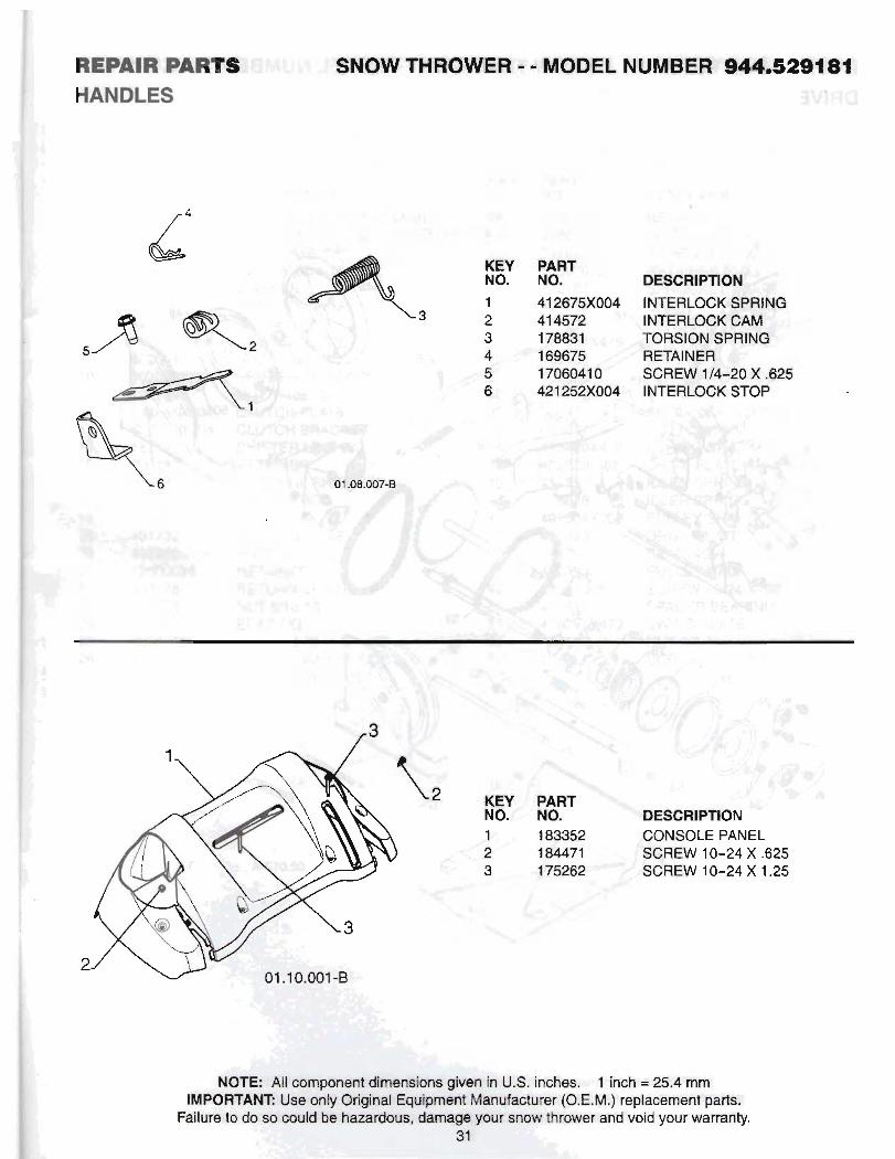
KEY PART NO* NO. 1 41 2675x004 2 41 457 2
iyt :fLr t i t , f j
2 ' 3; : J. 7
INTERLOCK WRING INTERLOCK 6 M TORSION SPRING RETAINER SCREW 1 /4-20 X ,625 INTERLOCK STOP
KEY NO. 1 2 3
PART NO. DESCRIPTION 1 83352 CONSOLE PANEL 1 84471 SC-REW 10-24 X .625
. . , . 9 - .,' - . .: . ~ . -4. - > - -; q A:;,
.. , .. "<..-= .'. ,% ; ;. : ' . - I 1 ,,., . >'C.
8 :.. 2 - :2: , '
3 , , ; ! ;$ ' :: :;!.;' 2% .'>< $:, .* .,
- . : .;, , . , I ,
.- ! I ..,
.& 4 ! ' W 8 4 I!::., I !:;.I
I .. I , . . li i.. !:T8!
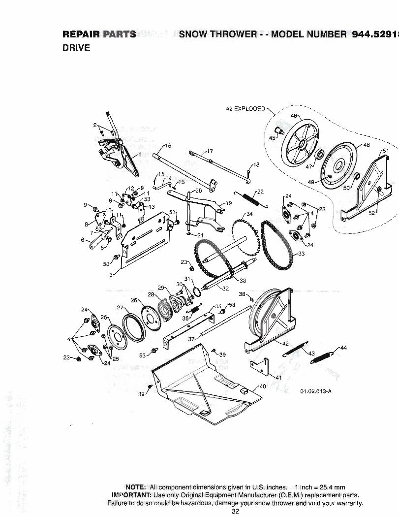
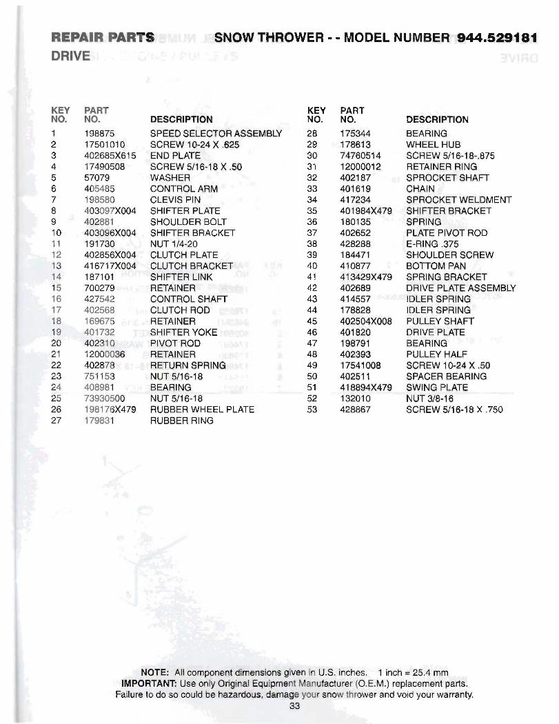
RwJLIm $!%'.I. ' SNOW THFKWER - - MODEL NUMBER @44.5.2@1( DRIVE - & -
; j " : . - ,
DRlVE
KEY NO. 1 < 2
B', 3 4 5 6 7 8 9 10 11 12 13 14 15 16 17 18 19 20 21 22 23 24 25 26 27
PART NO. 198875 17501 01 0 402685x61 5 1 7490508 57079 405485 198580 403097X004 402881 403093SX004 191 730 402856X004 41 671 7x004 1 871 01 700279 427542 402568 169675 401 732 40231 0 120000$$ 402878 751 159 408981 73930500 1 981 76x479 179831
WOW THROiWlR a MOOEL NUMBER .
DESCRIPTION SPEED SELECTOR ASSEMBLY SCREW 10-24 X .@28 END PLATE SCREW Ul6-18 X .$O WASHER CONTROL ARM CLEVIS PIN SHIFTER PLATE SHOULDER BOLT SHIFTER BRACKET NUT 1/4-20 CLUTCH PLATE CLUTCH BRACKET SHIFTER LINK RI%A{NER CONTROL SHAFT CLUTCH ROD RETAlNER SHIITER YOKE PIVOT ROD RrnAtNER WETURN SPRlNQ NUT Wl Q.18 BEARING4 NUT 511 6-1 8 RUBBER WHEEL PLATE RUBBER RING
KBY NO.
PART NO. DESCRIPTION
BEARING WHEEL HUB SCREW $1 8-1 %*.876 RETAINER RlNQ 8PROCKn $HAFT CHAIN dPR6CKm WELDMENT SMIfTER BRACKET OPRl NQ PLATE PIVOT ROD E-RING ,375 SHOULDER SCREW BOTTOM PAN SPRINQ BF?ACKET DRIVE PLBTE ASSEMBLY IDLER SPRINQ IDLER SPRINQ PULLEY SHAFT DRIVE PLATE BEARlNa PULLEY HALF SCREW 104i4 X .BQ SPACER BEARlNQ 8VVINQ PLATE NUT W8-I 8 SCREW 5Il8.18 X ,750

RWAIR ~ m " i 3 U r ' . THRWVfER - - MODEL NUMBER 944.5291 a b ,
+. 7
DRIVE
. , . . . ,
i 1 : - .-
I.. -.;-
:" ' 1 a 1b
,; a - 2
.: 3 - .. , .,
4 6,
,, , ,
5
! "
6 . I . . 7
PART Y : :;r. 1 &,L ' -
NO. I. ,,BESCRIPTIOFC ,,, A
1 ~ L E ASSEMBLY- ' , 44 . + . @ssyofla,lb)
179S2 l r ' WLE SHAFT Q#sMt -.a PIN 311 6 42t3Ql- '"' J' ' SPROCKET 1 7 4 W %MUST WASHER 173- ' =tBEARtNG 17- ' .'MOLT 5/16-18. X SS'. 1554rW :CLIKPIN
-'SQUARE KEY - 8 .
. . I . , ". . I
, - - ; $&> - . G I . ... 5". --'t4?1
%- - .I
--: %.A- q;.. . . . I - * .- : . ~ . , . ..
- .,; I T S ' ..< . .
j ,
. 1,
, .
\ . . . , .
< .
mponent dimensions given in U.S. inche$ $..., &@ch = 25.4 mm PORTANT Use only Original Equipment Manufacturer (O.E.M.) replacement parts.
id be hazardous, damage your snow thrower and void your warranty.
$4

F)Ep&lR PARTS :rb, r" + SNOW THROWER - - MODEL NUMBER ~U.SP9482 CHASSIS I ENGINE I PULLEYS
-3 t d l . , ,- , - 1 . . , . , :,,.yg'd i "4 t -. *,- r ' <
KEY'' M NQ., m. D.E.g-CRIP'IION -. s r r B&S ENGINE MODEL
1 L
15C113-1366-E8 1 41 8694x61 5 FRAME e 150406 BOLT 3/84 6 3 ,428867 BCREW !5/le-18 X .%Q
KEY NO. 1
a,
PART NO2 4 2 4 85x61 5 ENGINE MOUFfT1FK;kPLAf&
AU es. 1 in& = 2 g $ m (O.E.M.) replacement pBft8.
F~UURB to do SO agubBW :Wid yQtJF b?+wtay+

R B ~ ~ R R & R T ~ :~.'i:!~- SNOW THROWER - - MOBEL NUMBER 944.52@41
CHASSIS / ENGINE / PULLEYS cJ ., c .= . . . . . . -
* ' , ;
KEY NO.
PART NO. B - m o h l 408007 IMEUR ~r 41 9744 irlwm3M- 423723x479 t M AFM BMEKET
,. , - - . *.,. - .- -, I.,.
-. . -. , --. : .

REPAIR M T 8 SNQW THROWER - * M m t NUMBBPt 16-"34 WHEELS
KEY NO. I 2
PART NO. DESCRIPTION 18'7831 X417 WHEEL A6Se;MBW U.1 187886X417 WHEEL ASSEMBLY RH
- - -_ * . r i . .
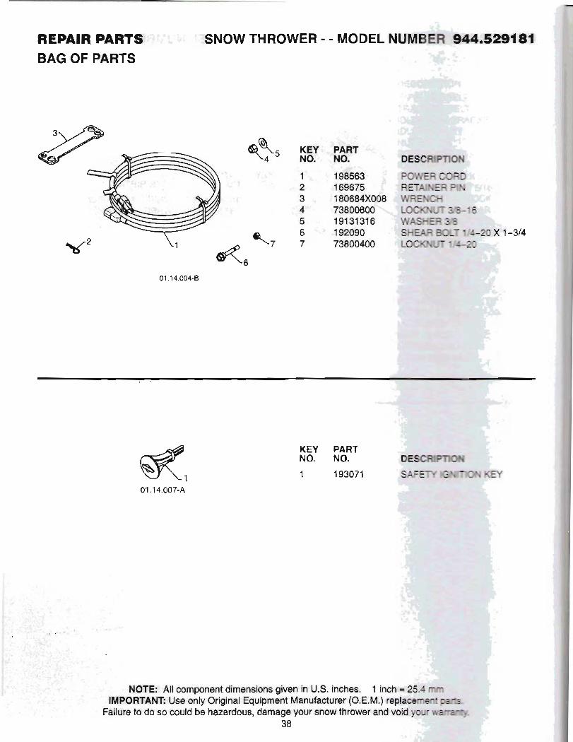
REPAIR PARTS a?;: $. $*SNOW THROWER CUMOREL NUMBER -84461 BAG OF PARTS
KEY PART NO. NO. 1 1 93071
NOTIEBsA11 component dimensions given in U.S. inches' NTi Uee only Original Equipment Manufacturer (O.E. so could be hamdous, damageyour snow thrower
38
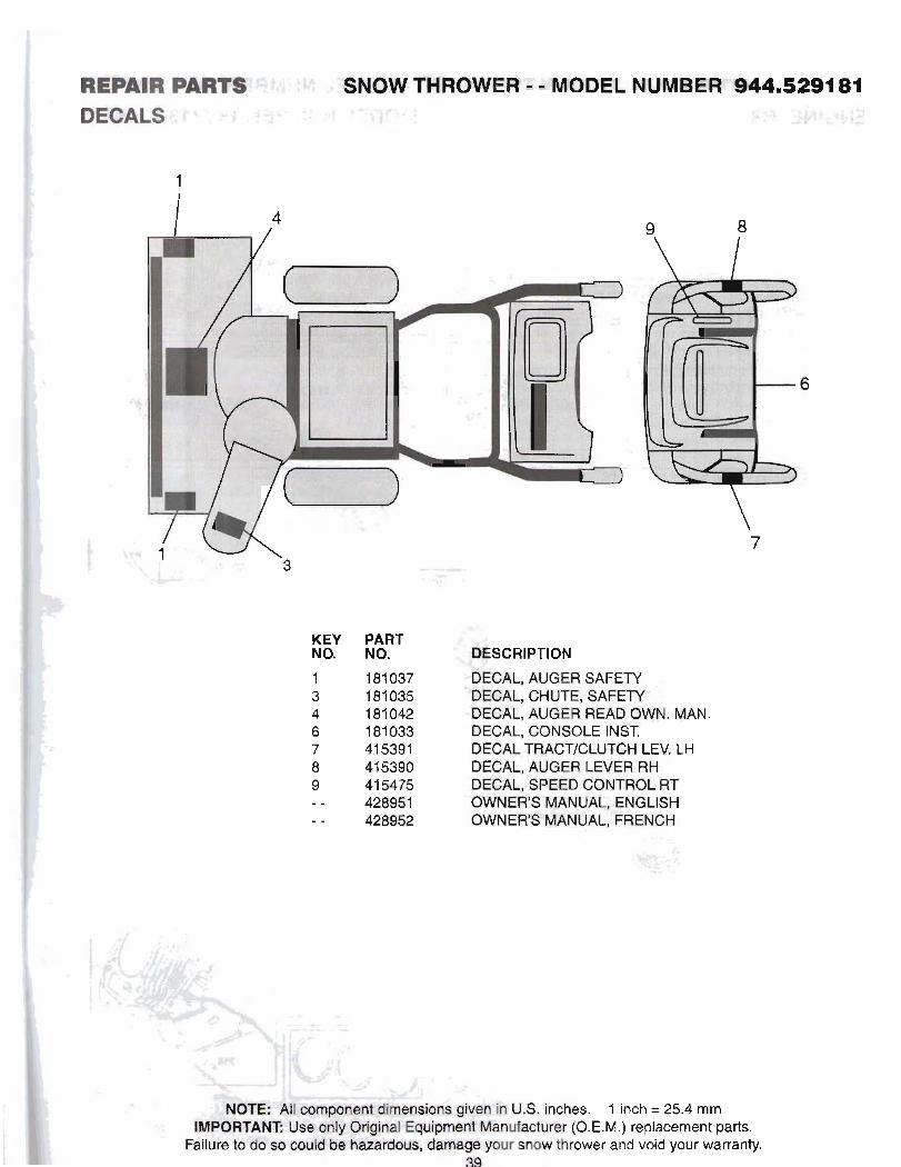
RWAER PAWfS!Sf?i\ \M -iiTSNOW THROWERZJ MODEL NUMBER S44 dBfi . t = , j t '" " DECALS - . - J $ 2 i h - . v z r, ~+, j ,+~g;f -h rr 2 . d
KEY PART NO. NO.
- . ' i ..
i '
' C .5 -
. . . ,
- .
. ._ ... .
. # . : y.,; ' , , ~ ,+:,
, . ' I .
j; :,
y- ,~ ~,i ,,: .-,k:*:.=.k
"" :. -' - . ,
d l '
RBWW PARTSkG:dYI:+3j . SNOW THROWER - - MODEL NUMBER 944.529181 ~ M Q ~ ~ V E , ~ & S p ~ j . + i . . , i j ~ ~ ;-y:::.9f: MODEL NUMBER 15C113-1365-E8

Printed in the U.S.A.
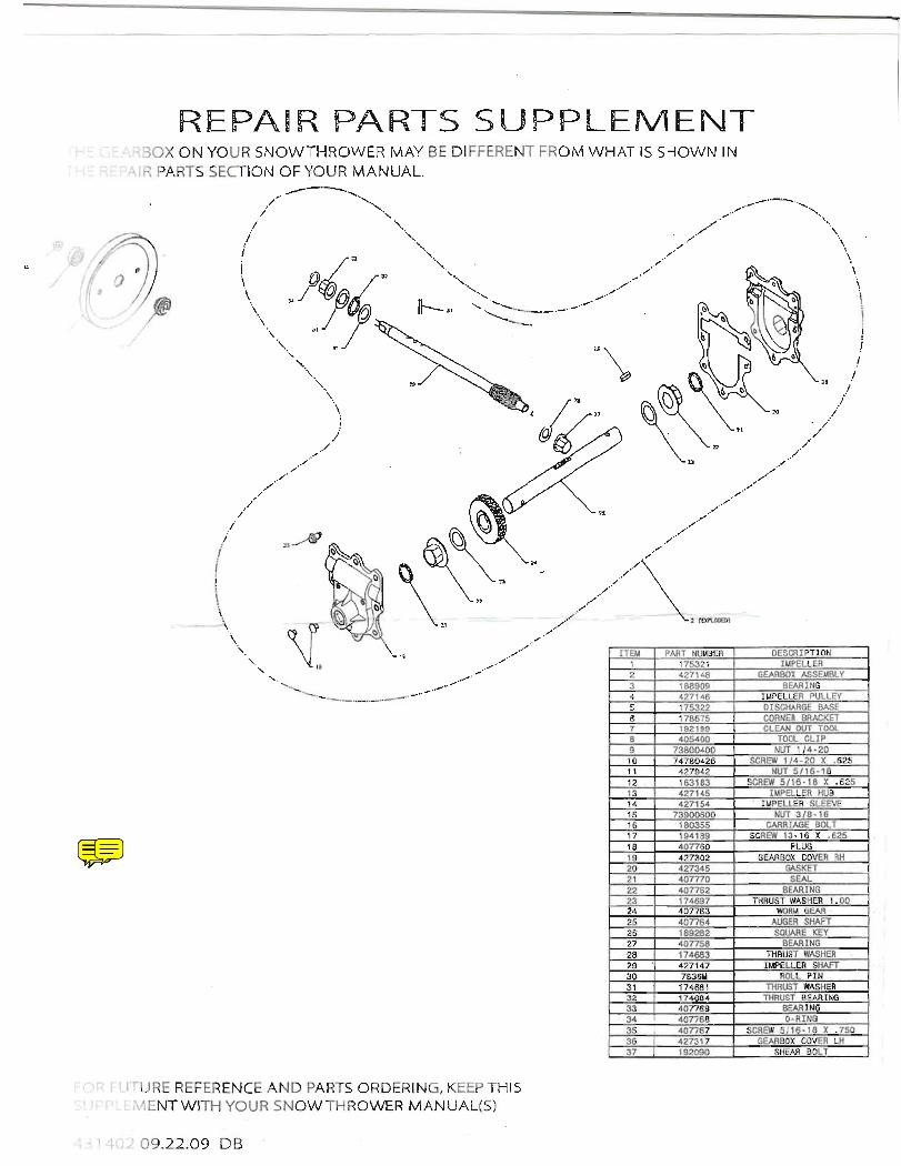
REPAIR PARTS SUPPLEMENT i t-+i GEARBOX O N YOUR SNOWTHROWER MAY BE DIFFERENT FROM WHAT IS SHOWN IN ! i-1: REPAiR PARTS SECTION OF YOUR MANUAL
FOR FUTURE CE AND PART5 QmmNa S U P P L E M M W WCTR W a W m W M A N W R