sección 4 section 4 sistemas de soportería cable …conector de charola a caja. • frame type box...
TRANSCRIPT

CH
AR
OLA
S P
rodu
ctos
Cro
ss L
ine
54
1. Charola tipo Escalera • Ladder Type Cable Tray
2. Charola tipo Fondo Sólido Perforado • Ventilated Solid Flat Trough Cable Tray
3. Charola Tipo Fondo Sólido Liso. • Solid Flat Trough Cable Tray
4. Conector. • Splice Plate
5. Curva Horizontal. • Horizontal Bend
6. “T” Horizontal • Horizontal Tee
7. Equis Horizontal. • Horizontal Cross.
8. Curva Vertical Interior y Exterior • Outside and Insi-de Vertical Bend.
9. “T” Vertical. • Vertical Tee
10. Reducción. • Reducer.
11. Conector de Charola a Caja. • Frame Type Box Connector
12. Barrera Separadora. • Straight Section Barrier Strip
13. Tapas (Cubiertas) • Covers
Sección 4 Sistemas de soportería
para cables
Section 4 Cable tray systems

55
CA
BLE
TR
AYS
Cro
ss L
ine
Pro
duct
sCertificaciones
CERTIFICADO
DE CONFORMIDAD
DE PRODUCTO
Certificado No.:201001C08148
Este Certificado sustituye al Certificado número: 200901C09542
Página 1 de 2
La Asociación de Normalización y Certificación, A.C., en su cáracter de organismo de Certificación de Producto acreditado y
aprobado en los términos de la Ley Federal sobre Metrología y Normalización (LFMN), de conformidad con los artículos 1, 2, 3
fracciones III, IV-A, XII, XV-A, 38 fracción VI, 52, 53, 68, 70, 70-C, 73, 74, 79, 80, y demás relativos y aplicables de la misma
Ley, así como de su respectivo reglamento, con número de Acreditación 01/10 vigente a partir del 09/03/2010, en atención a la
solicitud con número de Referencia 2007ART00294A/3 de acuerdo al procedimiento de Certificación PROPARCER-10 de
ANCE, otorga el presente Certificado de Conformidad de Producto a:
Titular: CORPORACIÓN MANDRINKA, S.A. DE C.V.
Nombre genérico : SOPORTE PARA CABLES TIPO CHAROLA
MALLA
NINGUNO
Tipo(s):
Subtipo(s):
Marca(s): CROSS LINE
Categoría: NUEVO
Modalidad: PROCEDIMIENTO ANCE
Fabricado y/o importado por: CORPORACIÓN MANDRINKA, S.A. DE C.V.
Bodega : ALESSANDRO VOLTA No. 1 Y 2 INT. S/N COL. PARQUE IND. CUAMATLA DEL. CUAUTITLÁN
IZCALLI C.P. 54730 EDO. DE MÉXICO
Fábrica: ALESSANDRO VOLTA No. 1 Y 2 INT. S/N COL. PARQUE IND. CUAMATLA DEL. CUAUTITLÁN
IZCALLI C.P. 54730 EDO. DE MÉXICO
País(es) de origen: MEXICO
Modelo(s): CL-CL CL (SEGUIDO O NO: -CL)
Especificaciones: Clasificación: 6 BB Ancho: 600 mm Largo: 3 m Malla: 100 mm x 50 mm
Material: Acero Inoxidable
FORCER-P03.07.10
CERTIFICADO
DE CONFORMIDAD
DE PRODUCTO
Certificado No.:201001C08168
Este Certificado sustituye al Certificado número: 200901C09521
Página 1 de 2
La Asociación de Normalización y Certificación, A.C., en su cáracter de organismo de Certificación de Producto acreditado y
aprobado en los términos de la Ley Federal sobre Metrología y Normalización (LFMN), de conformidad con los artículos 1, 2, 3
fracciones III, IV-A, XII, XV-A, 38 fracción VI, 52, 53, 68, 70, 70-C, 73, 74, 79, 80, y demás relativos y aplicables de la misma
Ley, así como de su respectivo reglamento, con número de Acreditación 01/10 vigente a partir del 09/03/2010, en atención a la
solicitud con número de Referencia 2007ART00287A/3 de acuerdo al procedimiento de Certificación PROPARCER-10 de
ANCE, otorga el presente Certificado de Conformidad de Producto a:
Titular: CORPORACIÓN MANDRINKA, S.A. DE C.V.
Nombre genérico : SOPORTE METÁLICO PARA CABLES
MALLA
CHAROLA
Tipo(s):
Subtipo(s):
Marca(s): CROSS LINE
Categoría: NUEVO
Modalidad: PROCEDIMIENTO ANCE
Fabricado y/o importado por: CORPORACIÓN MANDRINKA, S.A. DE C.V.
Bodega : ALESSANDRO VOLTA No. 1 Y 2 INT. S/N COL. PARQUE IND. CUAMATLA DEL. CUAUTITLÁN
IZCALLI C.P. 54730 EDO. DE MÉXICO
Fábrica: ALESSANDRO VOLTA No. 1 Y 2 INT. S/N COL. PARQUE IND. CUAMATLA DEL. CUAUTITLÁN
IZCALLI C.P. 54730 EDO. DE MÉXICO
País(es) de origen: MEXICO
Modelo(s): CL (Seguido o no: -CL)
Especificaciones: MATERIAL: ACERO GALVANIZADO ELECTROLÍTICO
ESPACIAMIENTO ENTRE APOYOS: 1,80 m
DIMENSIONES: LARGO: 3 000 mm ANCHO: 300 mm
CLASIFICACIÓN: 6BB
FORCER-P03.07.10

CH
AR
OLA
S P
rodu
ctos
Cro
ss L
ine
56
Se considera un sistema de soportería tipo charola para cable a una estructura rígida y continua especialmente construida para soportar cables, tubos u otras canalizaciones, las cuales pueden ser de metal u otros materiales no combustibles.
Las charolas para cables CROSS LINE pueden usarse para soportar cables de fuerza, alumbrado, control y señalización que cuenten con aislamiento y cubierta apropiados para este tipo de instalación.
Las charolas CROSS LINE se encuentran disponibles en materiales y acabados adecuados para su instalación a la intemperie o en condiciones ambientales desfavorables.
No se permite su instalación en cubos de ascensores o en aquellos lugares donde estén expuestos a daños mecánicos severos o en áreas clasificadas de acuerdo a los artículos del 500 al 505 de la norma NOM-001 SEDE 2012, a menos que los cables estén aprobados para tal uso.
Las charolas para cables de CROSS LINE cuentan con la suficiente rigidez y resistencia mecánica para proporcionar un soporte adecuado a todo el cableado tendido dentro de ellas.
CROSS LINE cuenta con una amplia gama de charolas metálicas protegidas contra la corrosión, así como no metálicas e incluyen todos los accesorios necesarios para realizar cambios de dirección o de nivel requeridos durante la instalación.
Todas las labores de diseño y fabricación de las charolas CROSS LINE se realizan apegados a las normas tanto nacionales (NMX-J511-ANCE-2011, NOM-001 SEDE 2012) como internacionales (NEMA VE 1-2002, Nacional Electrical Code NEC).
De esta manera el cálculo de las características de un sistema de soportería , tal como ancho, alturas, radios, distancia entre travesaños, etc. Deberá apegarse al artículo 318 de la norma NOM-001 SEDE 2012 o su similar en el código NEC.
El propósito de este catálogo de soportería para cables es el de ayudar a Ingenieros, Proyectistas y Compradores en la selección del material idóneo que cumpla con las características obtenidas en los cálculos indicados en las normas.
Debido a nuestra política de mejora continua de nuestros productos, las especificaciones, dimensiones, así como toda información contenida en este catálogo podrá ser modificada sin previo aviso.
Estamos seguros de que las ventajas que usted encontrará en nuestro sistema de soportería para cables, le convencerán de que:
¡¡¡EN CHAROLAS SEGUIMOS SIENDO LA MEJOR OPCIÓN!!!
A cable tray system is considered as a rigid and continuous metallic structure or other type of non-flammable materials which are built specially to support cable, pipes or others types of electrical channels.
CROSS LINE cable trays can be used as support of different cable type such as power, lighting systems, control or data signals. The cable must have the proper insulation according to the installation type.
CROSS LINE cable trays are available in materials and finishes for outdoors or hostile environment conditions.
Cable tray systems can´t be installed in elevators shafts or areas exposed to mechanical damage.
Cable tray systems can´t be installed in hazardous locations as indicated in articles 500 to 505 of the NEC code unless use a cable approved for this areas.
CROSS LINE cable tray systems are rigid and high mechanical resistance for a proper support of all cables contained inside.
CROSS LINE offers a wide range of cable trays like corrosion resistance metallic systems and non-metallic system, both have the necessary fitting for direction and level changes to offer a complete installation service.
The entire CROSS LINE cable tray’s manufacturing processes, from design to finish are under Mexican (NMX-J511-ANCE-2011, NOM-001 SEDE 2012) as International (NEMA VE 1-2002, National Electrical Code NEC) standards.
So the calculation of cable tray parameters such as width, height, radius, distance between rungs and others, should be according to 318 article of NEC code or NOM-001 SEDE 2012 in Mexico.
This cable tray systems catalog is designed to help general engineers, project engineers and customers for a right cable tray selection, to fulfill the requirements obtained of the standard calculations.
CROSS LINE have a “continuous best product” policy, so the dimensions, specifications and all technical information showed in this catalog can change without notice.
While every effort has been made to assure the accuracy of information contained in this catalog at the time of publication, we cannot accept responsibility for inaccuracies resulting from undetected errors or omissions.
We are sure that the advantages of our cable tray system will convince you that:
IN CABLE TRAY SYSTEMS CROSS LINE IS YOUR BEST CHOICE!!!
57
CA
BLE
TR
AYS
Cro
ss L
ine
Pro
duct
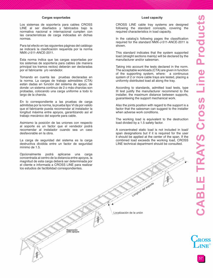
sCargas soportadas
Los sistemas de soportería para cables CROSS LINE al ser diseñados y fabricados bajo la normativa nacional e internacional cumplen con las características de carga indicadas en dichas normas.
Para tal efecto en las siguientes páginas del catálogo se indicará la clasificación requerida por la norma NMX-J-511-ANCE-2011.
Esta norma indica que las cargas soportadas por los sistemas de soportería para cables (de manera principal los tramos rectos) deberán ser declaradas por el fabricante y/o vendedor.
Tomando en cuenta las pruebas declaradas en la norma. La cargas de trabajo admisibles (CTA) están dadas en función del sistema de apoyo, de donde: un sistema continuo de 2 o más charolas son probadas, colocando una carga uniforme a todo lo largo de la charola.
En lo correspondiente a las pruebas de carga admitidas por la norma, la prueba tipo VI da por valido que el fabricante pueda recomendar al instalador la longitud máxima entre apoyos, garantizando así el trabajo mecánico del soporte para cable.
Asimismo la posición de las uniones con respecto al soporte es un factor que el vendedor podrá recomendar al instalador cuando sea un caso desfavorable en la obra.
La carga de seguridad del sistema es la carga destructiva dividida entre un factor de seguridad mínimo de 1.5.
Opcionalmente podrá aplicarse una carga concentrada al centro de la distancia entre apoyos, la magnitud de esta carga deberá ser determinada por el cliente e informada a CROSS LINE para realizar los estudios de factibilidad correspondientes.
Load capacity
CROSS LINE cable tray systems are designed following the standard concepts, covering the required characteristics in load capacity.
In the catalog’s following pages the classification required for the standard NMX-J-511-ANCE-2011 is shown.
This standard indicates that the system supported load (straight sections mainly) will be declared by the manufacturer and/or salesman.
Taking into account the tests declared in the norm. The acceptable workloads (CTA) are given in function of the supporting system, where: a continuous system of 2 or more cable trays are tested, placing a uniformly distributed load all along the tray.
According to standards, admitted load tests, type III test justify the manufacturer recommend to the installer, the maximum distance between supports, guaranteeing the support mechanical work.
Also the joints position with regard to the support is a factor that the salesman can suggest to the installer when adverse work conditions.
The working load is equivalent to the destruction load divided by a 1.5 safety factor.
A concentrated static load is not included in load/span designations but if it is required for the user it should be applied at the center of the span. If the combined load exceeds the working load, CROSS LINE technical department should be consulted.
Separaciónentre apoyos

CH
AR
OLA
S P
rodu
ctos
Cro
ss L
ine
58
Sección 4.1Soportería para cables
tipo escalera
Section 4.1Ladder type cable tray
systemsSecciones tipo “Z” • “Z” form sections
Secciones tipo “C” con ceja hacia adentro • Flange in “C” form sections
Secciónes tipo “I” • “I” Form sections
Peralte NominalSide rail height
Peralte ÚtilLoading Depth
Sufijo p/peralteRail height Suffix
Clase NEMANEMA Class
AluminioAluminum
AceroSteel
82.5 (3.25) 58.1 (2.29) 1 8A12C/16B
82.5 (3.25) 56.5 (2.22) 1 8C101.6 (4) 75.6 (2.98) 2 12A
12C/16A101.6 (4) 75.6 (2.98) 2 12B
114.3 (4.5) 88.3 (3.48) 3 12B 12C/16A127.0 (5) 101.4 (3.98) 5 12C 20A152.4 (6) 126.4 (4.98) 6 16C 20C177.8 (7) 151.9 (5.98) 7 12A 20A
Peralte NominalSide rail height
Peralte ÚtilLoading Depth
Sufijo p/peralteRail height Suffix
Clase NEMANEMA Class
AluminioAluminum
AceroSteel
82.5 (3.25) 58.1 (2.29) 1 12A 12B101.6 (4) 75.6 (2.98) 2 12B 12C/16A
114.3 (4.5) 88.3 (3.48) 3 12A 12C/16A127.0 (5) 101.4 (3.98) 5 12A 16B152.4 (6) 126.4 (4.98) 6 16C
20B152.4 (6) 126.4 (4.98) 6 20C
Peralte NominalSide rail height
Peralte ÚtilLoading Depth
Sufijo p/peralteRail height Suffix
Clase NEMANEMA Class
AluminioAluminum
101.6 (4) 75.6 (2.98) 2 8A104.6 (4.120) 78.6 (3.10) 2 12B106.7 (4.200) 80.7 (3.17) 2 12C/16A
127 (5) 101.4 (3.98 5 12C/16A152.4 (6) 126.4 (4.98) 6 12C/16A152.4 (6) 126.4 (4.98) 6 20B/20C
Las charolas con perfil “C” con el patín hacia afuera son solicitadas por escrito.Flanged out “C” rail cable trays are requested in the purchase order.
Perfil “I” solo en Aluminio • I form Aluminum only
Materiales y acabados:A: Aluminio acabado natural GI: Acero al carbón galvanizado por inmersión/ Lámina galvanizadaGE: Acero al carbón galvanizado electrolíticoT: Acero al carbón galvanizado tropicalizadoPVC: Acero al carbón recubierto con PVCPVA: Aluminio recubierto con PVCAI: Acero inoxidablePara materiales y acabados no indicados consulte nuestro departamento de ingeniería.Todas las Dimensiones en mm (pulg)
Materials&finishes:A: AA-6063 Natural finished aluminumGI: Hot dip galvanized steel / Galvanized sheetGE: Electro galvanized steelT: Chromium-zinc coated steelPVC: PVC coated steelPVA: PVC coated aluminumAI: Stainless steelFor materials and finishes not shown please consult our technical department.Dimensions are in mm (in)
PERALTENOMINALSIDE RAIL
HEIGHT
PERALTENOMINALSIDE RAIL
HEIGHT
PERALTENOMINALSIDE RAIL
HEIGHT
PERALTENOMINALSIDE RAIL
HEIGHT
PERALTEÚTIL
LOADINGDEPTH
PERALTEÚTIL
LOADINGDEPTH
PERALTEÚTIL
LOADINGDEPTH
PERALTE ÚTILLOADING DEPTH

59
CA
BLE
TR
AYS
Cro
ss L
ine
Pro
duct
sTramo recto • Straight section
Perfil tipoRail type
Material y acabadoMaterial and finish
A GI GE T PVC PVA AIZ 3.05 (10’) 3.66 (12’) 3.05 (10’) 3.05 (10’) 3.05 (10’) 3.05 (10’) 3.05 (10’)C 3.66 (12’) 3.66 (12’) 3.05(10’) 3.05(10’) 3.05(10’) 3.05(10’) 3.05(10’)I 6.10 (20’) 3.05(10’)
Ancho WWidth W
PasoRung spacing
PasoRung spacing
PasoRung spacing
152.4 (6) 228.6 (9) 304.8 (12) 152.4 (6) 228.6 (9) 304.8 (12) 152.4 (6) 228.6 (9) 304.8 (12)101.6 (4) CH-0406 CH-0409 CH-0412 CHC-0406 CHC-0409 CHC-0412 CHI-0406 CHI-0409 CHI-0412152.4 (6) CH-0606 CH-0609 CH-0612 CHC-0606 CHC-0609 CHC-0612 CHI-0606 CHI-0609 CHI-0612228.9 (9) CH-0906 CH-0909 CH-0912 CHC-0906 CHC-0909 CHC-0912 CHI-0906 CHI-0909 CHI-0912
304.8 (12) CH-1206 CH-1209 CH-1212 CHC-1206 CHC-1209 CHC-1212 CHI-1206 CHI-1209 CHI-1212406.4 (16) CH-1606 CH-1609 CH-1612 CHC-1606 CHC-1609 CHC-1612 CHI-1606 CHI-1609 CHI-1612457.2 (18) CH-1806 CH-1809 CH-1812 CHC-1806 CHC-1809 CHC-1812 CHI-1806 CHI-1809 CHI-1812508.0 (20) CH-2006 CH-2009 CH-2012 CHC-2006 CHC-2009 CHC-2012 CHI-2006 CHI-2009 CHI-2012609.6 (24) CH-2406 CH-2409 CH-2412 CHC-2406 CHC-2409 CHC-2412 CHI-2406 CHI-2409 CHI-2412762.0 (30) CH-3006 CH-3009 CH-3012 CHC-3006 CHC-3009 CHC-3012 CHI-3006 CHI-3009 CHI-3012914.4 (36 CH-3606 CH-3609 CH-3612 CHC-3606 CHC-3609 CHC-3612 CHI-3606 CHI-3609 CHI-3612
CH Z - 1209-1GIMaterial y acabado (ver pag 58) • Material & finishes (see page 58)Sufijo p/peralte • Rail height suffix Paso • Rung spacingAncho • WidthPerfil tipo (ver pag 58) • Rail type (see page 58)Tramo recto • Straight section
Longitudes estándar en metros (pies) • Standard length in meters (feet)Para longitudes diferentes consulte nuestro departamento de ingeniería • For other lengths please refer to our technical department
Todas las dimensiones en mm (pulg) • All dimensions are in mm (in)Pasos disponibles • Available rung spacings:152.4 (6), 228.6 (9), 304.8(12) y 457.2 (18)
Incluye 2 conectores y tornillería • Two connectors and hardware included
Selección de charola.
Para seleccionar adecuadamente una charola, deberá considerar los siguientes factores:
1) CLASE DE CHAROLAa) Capacidad de carga b) Espaciamiento entre soportec) Deflexión
2) ALTURA DE CHAROLAa) Diámetro de cablesb) Capacidad de relleno de cables
3) MATERIAL / ACABADOa) Medio ambienteb) Aparienciac) Costo de la instalación
4) ANCHO DE CHAROLAa) Diámetro de cablesb) Capacidad de relleno de cablesc) Requerimientos para futuras expansiones
Altura de charolas • Cable tray height
Cable trays selection
To choose adequately a cable tray you must consider the following factors:
1) CABLE TRAY TYPEa) Load capacity b) Support’s spaciousnessc) Deflection
2) CABLE TRAY’S HEIGHTa) Cable’s diameterb) Cables packing capacity
3) MATERIAL / FINISHa) Environmentb) Appearancec) Installation Cost
4) CABLE TRAY’S WIDEa) Cable’s diametersb) Cables packing capacityc) Future expansion requirements
Sufijo para peralte
Peralte Nominalmm (pulg.)
Peralte Útilmm (pulg.)
1 82.5 (3 ¼”) 56.5 (2.224”)2 101.6 (4”) 75.6 (2.976”)3 114.3 (4 ½”) 88.3 (3.476”)5 127.0 (5”) 101.0 (3.976”)6 152.4 (6”) 126.4 (4.976”)
W
½ Paso½ Rung spacing
PasoRung spacing

CH
AR
OLA
S P
rodu
ctos
Cro
ss L
ine
60
Curva horizontal a 45° y 90° • 45° & 90° Horizontal bend
Ancho WWidth W
RadioRadius
203.2 (8) 304.8 (12) 609.6 (24) 914.4 (36)101.6 (4) VH**-04R890 VH**-04R1290 VH**-04R2490 VH**-04R3690152.4 (6) VH**-06R890 VH**-06R1290 VH**-06R2490 VH**-06R3690228.9 (9) VH**-09R890 VH**-09R1290 VH**-09R2490 VH**-09R3690
304.8 (12) VH**-12R890 VH**-12R1290 VH**-12R2490 VH**-12R3690406.4 (16) VH**-16R890 VH**-16R1290 VH**-16R2490 VH**-16R3690457.2 (18) VH**-18R890 VH**-18R1290 VH**-18R2490 VH**-18R3690508.0 (20) VH**-20R890 VH**-20R1290 VH**-20R2490 VH**-20R3690609.6 (24) VH**-24R890 VH**-24R1290 VH**-24R2490 VH**-24R3690762.0 (30) VH**-30R890 VH**-30R1290 VH**-30R2490 VH**-30R3690914.4 (36 VH**-36R890 VH**-36R1290 VH**-36R2490 VH**-36R3690
Ancho WWidth W
RadioRadius
203.2 (8) 304.8 (12) 609.6 (24) 914.4 (36)101.6 (4) VH**-04R845 VH**-04R1245 VH**-04R2445 VH**-04R3645152.4 (6) VH**-06R845 VH**-06R1245 VH**-06R2445 VH**-06R3645228.9 (9) VH**-09R845 VH**-09R1245 VH**-09R2445 VH**-09R3645
304.8 (12) VH**-12R845 VH**-12R1245 VH**-12R2445 VH**-12R3645406.4 (16) VH**-16R845 VH**-16R1245 VH**-16R2445 VH**-16R3645457.2 (18) VH**-18R845 VH**-18R1245 VH**-18R2445 VH**-18R3645508.0 (20) VH**-20R845 VH**-20R1245 VH**-20R2445 VH**-20R3645609.6 (24) VH**-24R845 VH**-24R1245 VH**-24R2445 VH**-24R3645762.0 (30) VH**-30R845 VH**-30R1245 VH**-30R2445 VH**-30R3645914.4 (36) VH**-36R845 VH**-36R1245 VH**-36R2445 VH**-36R3645
VHZ-12R890-1 AMaterial y acabado (ver pag 58) • Material & finishes (see page 58)Sufijo p/peralte (ver pag 58) • Rail height suffix (see page 58)Ángulo de la curva • Angle bendRadio • RadiusAncho • WidthPerfil tipo (ver pag 58)• Rail type (see page 58)Curva horizontal • Horizontal bend
Para curvas estructurales agregar la letra “E” después del código.
Números de catálogo para curva a 90° • 90° Bend’s Catalog number
Números de catálogo para curva a 45° • 45° Bend’s Catalog number
Diseño radial para perfil “Z” y “C”Radial design for “Z” & “C” rail type
Diseño estructural para perfil “Z”, “C” e “I”Segmented design for “Z”, “C” & “I” rail type
Todas las dimensiones en mm (pulg) • All dimensions are in mm (in)
Solo radial • Radial Only
Solo radial • Radial Only
Incluye 2 conectores y tornillería • Two connectors and hardware included
W
WW
WR
RR
R
90° 90°
45°
45°

61
CA
BLE
TR
AYS
Cro
ss L
ine
Pro
duct
sCurva vertical exterior a 45° Y 90° • 45° & 90° Outside vertical bendVEZ-12R890-1 A
Material y acabado (ver pag 58) • Material & finishes (see page 58)Sufijo p/peralte (ver pag 58) • Rail height suffix (see page 58)Ángulo de la curva • Angle bendRadio • RadiusAncho • WidthPerfil tipo (ver pag 58)• Rail type (see page 58)Curva vertical exterior • Outside vertical bend
Diseño radial para perfil “Z” y “C”Radial design for “Z” & “C” rail type
Diseño estructural para perfil “Z”, “C” e “I”Segmented design for “Z”, “C” & “I” rail type
Para curvas estructurales agregar la letra “E” después del código.
Ancho WWidth W
RadioRadius
203.2 (8) 304.8 (12) 609.6 (24) 914.4 (36)101.6 (4) VE**-04R890 VE**-04R1290 VE**-04R2490 VE**-04R3690152.4 (6) VE**-06R890 VE**-06R1290 VE**-06R2490 VE**-06R3690228.9 (9) VE**-09R890 VE**-09R1290 VE**-09R2490 VE**-09R3690
304.8 (12) VE**-12R890 VE**-12R1290 VE**-12R2490 VE**-12R3690406.4 (16) VE**-16R890 VE**-16R1290 VE**-16R2490 VE**-16R3690457.2 (18) VE**-18R890 VE**-18R1290 VE**-18R2490 VE**-18R3690508.0 (20) VE**-20R890 VE**-20R1290 VE**-20R2490 VE**-20R3690609.6 (24) VE**-24R890 VE**-24R1290 VE**-24R2490 VE**-24R3690762.0 (30) VE**-30R890 VE**-30R1290 VE**-30R2490 VE**-30R3690914.4 (36) VE**-36R890 VE**-36R1290 VE**-36R2490 VE**-36R3690
Ancho WWidth W
RadioRadius
203.2 (8) 304.8 (12) 609.6 (24) 914.4 (36)101.6 (4) VE**-04R845 VE**-04R1245 VE**-04R2445 VE**-04R3645152.4 (6) VE**-06R845 VE**-06R1245 VE**-06R2445 VE**-06R3645228.9 (9) VE**-09R845 VE**-09R1245 VE**-09R2445 VE**-09R3645
304.8 (12) VE**-12R845 VE**-12R1245 VE**-12R2445 VE**-12R3645406.4 (16) VE**-16R845 VE**-16R1245 VE**-16R2445 VE**-16R3645457.2 (18) VE**-18R845 VE**-18R1245 VE**-18R2445 VE**-18R3645508.0 (20) VE**-20R845 VE**-20R1245 VE**-20R2445 VE**-20R3645609.6 (24) VE**-24R845 VE**-24R1245 VE**-24R2445 VE**-24R3645762.0 (30) VE**-30R845 VE**-30R1245 VE**-30R2445 VE**-30R3645914.4 (36) VE**-36R845 VE**-36R1245 VE**-36R2445 VE**-36R3645
Números de catálogo para curva a 90° • 90° Bend’s Catalog number
Números de catálogo para curva a 45° • 45° Bend’s Catalog number
Todas las dimensiones en mm (pulg) • All dimensions are in mm (in)
Solo radial • Radial Only
Solo radial • Radial Only
Incluye 2 conectores y tornillería • Two connectors and hardware included
W
W
WW
R
R
R R
90°
90°
45°
45°

CH
AR
OLA
S P
rodu
ctos
Cro
ss L
ine
62
Curva vertical interior a 45° Y 90° • 45° & 90° Inside vertical bend
VIZ-12R890-1 A Material y acabado (ver pag 58) • Material & finishes (see page 58)Sufijo p/peralte (ver pag 58) • Rail height suffix (see page 58)Ángulo de la curva • Angle bendRadio • RadiusAncho • WidthPerfil tipo (ver pag 58)• Rail type (see page 58)Curva vertical interior • Inside vertical bend
Diseño radial para perfil “Z” y “C”Radial design for “Z” & “C” rail type
Diseño estructural para perfil “Z”, “C” e “I”Segmented design for “Z”, “C” & “I” rail type
Para curvas estructurales agregar la letra “E” después del código.
Ancho WWidth W
RadioRadius
203.2 (8) 304.8 (12) 609.6 (24) 914.4 (36)101.6 (4) VI**-04R890 VI**-04R1290 VI**-04R2490 VI**-04R3690152.4 (6) VI**-06R890 VI**-06R1290 VI**-06R2490 VI**-06R3690228.9 (9) VI**-09R890 VI**-09R1290 VI**-09R2490 VI**-09R3690
304.8 (12) VI**-12R890 VI**-12R1290 VI**-12R2490 VI**-12R3690406.4 (16) VI**-16R890 VI**-16R1290 VI**-16R2490 VI**-16R3690457.2 (18) VI**-18R890 VI**-18R1290 VI**-18R2490 VI**-18R3690508.0 (20) VI**-20R890 VI**-20R1290 VI**-20R2490 VI**-20R3690609.6 (24) VI**-24R890 VI**-24R1290 VI**-24R2490 VI**-24R3690762.0 (30) VI**-30R890 VI**-30R1290 VI**-30R2490 VI**-30R3690914.4 (36) VI**-36R890 VI**-36R1290 VI**-36R2490 VI**-36R3690
Ancho WWidth W
RadioRadius
203.2 (8) 304.8 (12) 609.6 (24) 914.4 (36)101.6 (4) VI**-04R845 VI**-04R1245 VI**-04R2445 VI**-04R3645152.4 (6) VI**-06R845 VI**-06R1245 VI**-06R2445 VI**-06R3645228.9 (9) VI**-09R845 VI**-09R1245 VI**-09R2445 VI**-09R3645
304.8 (12) VI**-12R845 VI**-12R1245 VI**-12R2445 VI**-12R3645406.4 (16) VI**-16R845 VI**-16R1245 VI**-16R2445 VI**-16R3645457.2 (18) VI**-18R845 VI**-18R1245 VI**-18R2445 VI**-18R3645508.0 (20) VI**-20R845 VI**-20R1245 VI**-20R2445 VI**-20R3645609.6 (24) VI**-24R845 VI**-24R1245 VI**-24R2445 VI**-24R3645762.0 (30) VI**-30R845 VI**-30R1245 VI**-30R2445 VI**-30R3645914.4 (36) VI**-36R845 VI**-36R1245 VI**-36R2445 VI**-36R3645
Números de catálogo para curva a 90° • 90° Bend’s Catalog number
Números de catálogo para curva a 45° • 45° Bend’s Catalog number
Todas las dimensiones en mm (pulg) • All dimensions are in mm (in)
Solo radial • Radial Only
Solo radial • Radial Only
Incluye 2 conectores y tornillería • Two connectors and hardware included
W W
W
W
R R
R
R
90° 90°45°
45°

63
CA
BLE
TR
AYS
Cro
ss L
ine
Pro
duct
s“T” Horizontal • Horizontal tee
THZ-12R8-1 AMaterial y acabado (ver pag 58) • Material & finishes (see page 58)Sufijo p/peralte (ver pag 58) • Rail height suffix (see page 58)Radio • RadiusAncho • WidthPerfil tipo (ver pag 58)• Rail type (see page 58)“T” Horizontal • Horizontal “T”
Diseño radial para perfil “Z” y “C”Radial design for “Z” & “C” rail type
Diseño estructural para perfil “Z”, “C” e “I”Segmented design for “Z”, “C” & “I” rail type
Para curvas estructurales agregar la letra “E” después del código.
Ancho WWidth W
Radio 203.2 solo radialRadius (8) radial only
Radio 304.8Radius (12)
No. de catálogoCatalog number A B No. de catálogo
Catalog number A B
101.6 (4) TH**-04R8 731 (28.78) 416 (16.39) TH**-04R12 864 (34) 518 (20.39)152.4 (6) TH**-06R8 782 (30.78) 467 (18.39) TH**-06R12 914 (36) 569 (22.39)228.9 (9) TH**-09R8 585 (23.03) 543 (21.39) TH**-09R12 991 (39) 645 (25.39)
304.8 (12) TH**-12R8 934 (36.78) 619 (24.39) TH**-12R12 1137 (44.78) 721 (28.39)406.4 (16) TH**-16R8 1036 (40.78) 721 (28.39) TH**-16R12 1239 (48.78) 823 (32.39)457.2 (18) TH**-18R8 1086 (42.78) 772 (30.39) TH**-18R12 1290 (50.78) 873 (34.39)508.0 (20) TH**-20R8 1137 (44.78) 823 (32.39) TH**-20R12 1341 (52.78) 924 (36.39)609.6 (24) TH**-24R8 1239 (48.78) 924 (36.39) TH**-24R12 1442 (56.78) 1026 (40.39)762.0 (30) TH**-30R8 1391 (54.78) 1077 (42.39) TH**-30R12 1595 (62.78) 1178 (46.39)914.4 (36) TH**-36R8 1543 (60.78) 1229 (48.39) TH**-36R12 1747 (68.78) 1331 (52.39)
Ancho WWidth W
Radio 609.6Radius (24)
Radio 914.4Radius (36)
No. de catálogoCatalog number A B No. de catálogo
Catalog number A B
101.6 (4) TH**-04R24 1544 (60.78) 823 (32.39) TH**-04R36 2153 (84.78) 1127 (44.39)152.4 (6) TH**-06R24 1595 (62.78) 873 (34.39) TH**-06R36 2204 (86.78) 1178 (46.39)228.9 (9) TH**-09R24 1671 (65.78) 950 (37.39) TH**-09R36 2280 (89.78) 1254 (49.39)
304.8 (12) TH**-12R24 1747 (68.78) 1030 (40.39) TH**-12R36 2357 (92.78) 1331 (52.39)406.4 (16) TH**-16R24 1849 (72.78) 1127 (44.39) TH**-16R36 2458 (96.78) 1432 (56.39)457.2 (18) TH**-18R24 1899 (74.78) 1178 (46.39) TH**-18R36 2509 (98.78) 1483 (58.39)508.0 (20) TH**-20R24 1950 (76.78) 1229 (48.39) TH**-20R36 2560 (100.78) 1534 (60.39)609.6 (24) TH**-24R24 2052 (80.78) 1331 (52.39) TH**-24R36 2661 (104.78) 1635 (64.39)762.0 (30) TH**-30R24 2204 (86.78) 1483 (58.39) TH**-30R36 2814 (110.78) 1788 (70.39)914.4 (36) TH**-36R24 2357 (92.78) 1635 (64.39) TH**-36R36 2966 (116.78) 1940 (76.39)
Todas las dimensiones en mm (pulg) • All dimensions are in mm (in)Incluye 2 conectores y tornillería • Two connectors and hardware included
A A
R R
B B
W WW W

CH
AR
OLA
S P
rodu
ctos
Cro
ss L
ine
64
Ancho WWidth W
Radio 203.2 solo radialRadius (8) radial only
Radio 304.8Radius (12)
No. de catálogoCatalog number A No. de catálogo
Catalog number A
101.6 (4) XH**-04R8 731 (28.78) XH**-04R12 864 (34)152.4 (6) XH**-06R8 782 (30.78) XH**-06R12 914 (36)228.9 (9) XH**-09R8 585 (23.03) XH**-09R12 991 (39)
304.8 (12) XH**-12R8 934 (36.78) XH**-12R12 1137 (44.78)406.4 (16) XH**-16R8 1036 (40.78) XH**-16R12 1239 (48.78)457.2 (18) XH**-18R8 1086 (42.78) XH**-18R12 1290 (50.78)508.0 (20) XH**-20R8 1137 (44.78) XH**-20R12 1341 (52.78)609.6 (24) XH**-24R8 1239 (48.78) XH**-24R12 1442 (56.78)762.0 (30) XH**-30R8 1391 (54.78) XH**-30R12 1595 (62.78)914.4 (36) XH**-36R8 1543 (60.78) XH**-36R12 1747 (68.78)
Ancho WWidth W
Radio 609.6Radius (24)
Radio 914.4Radius (36)
No. de catálogoCatalog number A No. de catálogo
Catalog number A
101.6 (4) XH**-04R24 1544 (60.78) XH**-04R36 2153 (84.78)152.4 (6) XH**-06R24 1595 (62.78) XH**-06R36 2204 (86.78)228.9 (9) XH**-09R24 1671 (65.78) XH**-09R36 2280 (89.78)
304.8 (12) XH**-12R24 1747 (68.78) XH**-12R36 2357 (92.78)406.4 (16) XH**-16R24 1849 (72.78) XH**-16R36 2458 (96.78)457.2 (18) XH**-18R24 1899 (74.78) XH**-18R36 2509 (98.78)508.0 (20) XH**-20R24 1950 (76.78) XH**-20R36 2560 (100.78)609.6 (24) XH**-24R24 2052 (80.78) XH**-24R36 2661 (104.78)762.0 (30) XH**-30R24 2204 (86.78) XH**-30R36 2814 (110.78)914.4 (36) XH**-36R24 2357 (92.78) XH**-36R36 2966 (116.78)
“X” Horizontal • Horizontal cross
XHZ-12R8-1 A EE = estructural, radial omitir • E = segmented, avoid if radialMaterial y acabado (ver pag 58) • Material & finishes (see page 58)Sufijo p/peralte (ver pag 58) • Rail height suffix (see page 58)Radio • RadiusAncho • WidthPerfil tipo (ver pag 58)• Rail type (see page 58)“X” horizontal • Horizontal cross
Diseño radial para perfil “Z” y “C”Radial design for “Z” & “C” rail type
Diseño estructural para perfil “Z”, “C” e “I”Segmented design for “Z”, “C” & “I” rail type
Todas las dimensiones en mm (pulg) • All dimensions are in mm (in)Incluye 2 conectores y tornillería • Two connectors and hardware included
WA R
A
WA
R
A
65
CA
BLE
TR
AYS
Cro
ss L
ine
Pro
duct
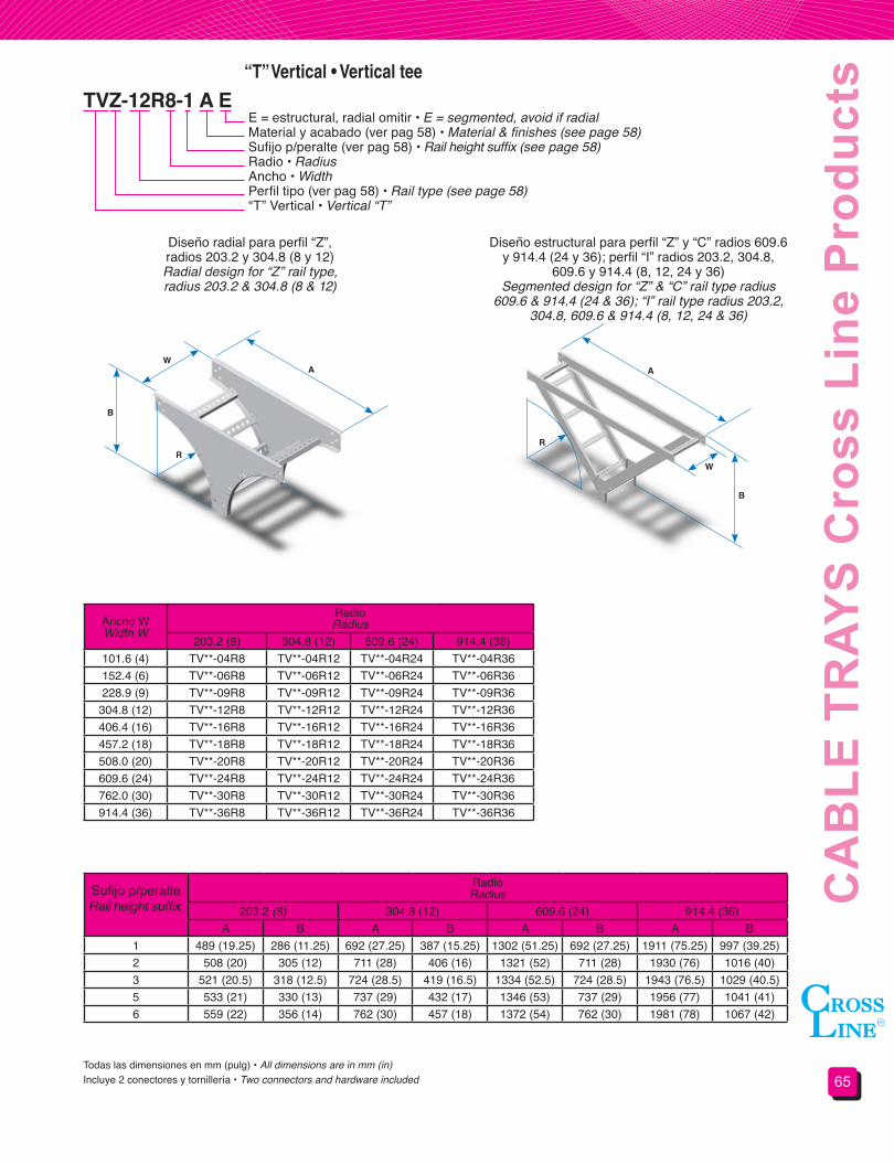
s“T” Vertical • Vertical tee
TVZ-12R8-1 A EE = estructural, radial omitir • E = segmented, avoid if radialMaterial y acabado (ver pag 58) • Material & finishes (see page 58)Sufijo p/peralte (ver pag 58) • Rail height suffix (see page 58)Radio • RadiusAncho • WidthPerfil tipo (ver pag 58) • Rail type (see page 58)“T” Vertical • Vertical “T”
Diseño radial para perfil “Z”,radios 203.2 y 304.8 (8 y 12)Radial design for “Z” rail type,radius 203.2 & 304.8 (8 & 12)
Diseño estructural para perfil “Z” y “C” radios 609.6 y 914.4 (24 y 36); perfil “I” radios 203.2, 304.8,
609.6 y 914.4 (8, 12, 24 y 36)Segmented design for “Z” & “C” rail type radius
609.6 & 914.4 (24 & 36); “I” rail type radius 203.2, 304.8, 609.6 & 914.4 (8, 12, 24 & 36)
Ancho WWidth W
RadioRadius
203.2 (8) 304.8 (12) 609.6 (24) 914.4 (36)101.6 (4) TV**-04R8 TV**-04R12 TV**-04R24 TV**-04R36152.4 (6) TV**-06R8 TV**-06R12 TV**-06R24 TV**-06R36228.9 (9) TV**-09R8 TV**-09R12 TV**-09R24 TV**-09R36
304.8 (12) TV**-12R8 TV**-12R12 TV**-12R24 TV**-12R36406.4 (16) TV**-16R8 TV**-16R12 TV**-16R24 TV**-16R36457.2 (18) TV**-18R8 TV**-18R12 TV**-18R24 TV**-18R36508.0 (20) TV**-20R8 TV**-20R12 TV**-20R24 TV**-20R36609.6 (24) TV**-24R8 TV**-24R12 TV**-24R24 TV**-24R36762.0 (30) TV**-30R8 TV**-30R12 TV**-30R24 TV**-30R36914.4 (36) TV**-36R8 TV**-36R12 TV**-36R24 TV**-36R36
Sufijo p/peralteRail height suffix
RadioRadius
203.2 (8) 304.8 (12) 609.6 (24) 914.4 (36)A B A B A B A B
1 489 (19.25) 286 (11.25) 692 (27.25) 387 (15.25) 1302 (51.25) 692 (27.25) 1911 (75.25) 997 (39.25)2 508 (20) 305 (12) 711 (28) 406 (16) 1321 (52) 711 (28) 1930 (76) 1016 (40)3 521 (20.5) 318 (12.5) 724 (28.5) 419 (16.5) 1334 (52.5) 724 (28.5) 1943 (76.5) 1029 (40.5)5 533 (21) 330 (13) 737 (29) 432 (17) 1346 (53) 737 (29) 1956 (77) 1041 (41)6 559 (22) 356 (14) 762 (30) 457 (18) 1372 (54) 762 (30) 1981 (78) 1067 (42)
Todas las dimensiones en mm (pulg) • All dimensions are in mm (in)Incluye 2 conectores y tornillería • Two connectors and hardware included
AW
B
R
A
W
B
R
CH
AR
OLA
S P
rodu
ctos
Cro
ss L
ine
66
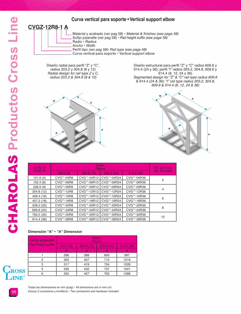
Diseño radial para perfil “Z” y “C”,radios 203.2 y 304.8 (8 y 12)
Radial design for rail type Z y C,radius 203.2 & 304.8 (8 & 12)
Diseño estructural para perfil “Z” y “C” radios 609.6 y 914.4 (24 y 36); perfil “I” radios 203.2, 304.8, 609.6 y
914.4 (8, 12, 24 y 36)Segmented design for “Z” & “C” rail type radius 609.6
& 914.4 (24 & 36); “I” rail type radius 203.2, 304.8, 609.6 & 914.4 (8, 12, 24 & 36)
Ancho WWidth W
RadioRadius No. ganchos
No. of hooks203.2 (8) 304.8 (12) 609.6 (24) 914.4 (36)
101.6 (4) CVG**-04R8 CVG**-04R12 CVG**-04R24 CVG**-04R362
152.4 (6) CVG**-06R8 CVG**-06R12 CVG**-06R24 CVG**-06R36228.9 (9) CVG**-09R8 CVG**-09R12 CVG**-09R24 CVG**-09R36
4304.8 (12) CVG**-12R8 CVG**-12R12 CVG**-12R24 CVG**-12R36406.4 (16) CVG**-16R8 CVG**-16R12 CVG**-16R24 CVG**-16R36
6457.2 (18) CVG**-18R8 CVG**-18R12 CVG**-18R24 CVG**-18R36508.0 (20) CVG**-20R8 CVG**-20R12 CVG**-20R24 CVG**-20R36
8609.6 (24) CVG**-24R8 CVG**-24R12 CVG**-24R24 CVG**-24R36762.0 (30) CVG**-30R8 CVG**-30R12 CVG**-30R24 CVG**-30R36
12914.4 (36) CVG**-36R8 CVG**-36R12 CVG**-36R24 CVG**-36R36
Sufijo p/peralteRail height suffix
RadioRadius
203.2 (8) 304.8 (12) 609.6 (24) 914.4 (36)A A A A
1 286 388 693 9972 305 407 712 10163 317 419 724 10285 330 432 737 10416 355 457 762 1066
Curva vertical para soporte • Vertical support elbow
CVGZ-12R8-1 AMaterial y acabado (ver pag 58) • Material & finishes (see page 58)Sufijo p/peralte (ver pag 58) • Rail height suffix (see page 58)Radio • RadiusAncho • WidthPerfil tipo (ver pag 58)• Rail type (see page 58)Curva vertical para soporte • Vertical support elbow
Todas las dimensiones en mm (pulg) • All dimensions are in mm (in)Incluye 2 conectores y tornillería • Two connectors and hardware included
AW
AR
AW
A
R
Dimensión “A” • “A” Dimension

67
CA
BLE
TR
AYS
Cro
ss L
ine
Pro
duct
s
CAZ-12-1 A
DY * Z-12-1 A
Curva horizontal ajustable • Horizontal adjustable bend
Derivación horizontal a 45° • 45° Horizontal wye branch
Material y acabado (ver pag 58) • Material & finishes (see page 58)Sufijo p/peralte (ver pag 58) • Rail height suffix (see page 58)Ancho • WidthPerfil tipo (ver pag 58) • Rail type (see page 58)Curva horizontal ajustable • Horizontal adjustable bend
Material y acabado (ver pag 58) • Material & finishes (see page 58)Sufijo p/peralte (ver pag 58) • Rail height suffix (see page 58)Ancho • WidthPerfil tipo (ver pag 58)• Rail type (see page 58)Colocar “D” para derecha o “I” izquierda • Add “D” for right or “I” for leftDerivación horizontal a 45° • 45° horizontal wye branch
Ancho WWidth W
No. de catálogoCatalog number
101.6 (4) CA*-04152.4 (6) CA*-06228.9 (9) CA*-09
304.8 (12) CA*-12406.4 (16) CA*-16457.2 (18) CA*-18508.0 (20) CA*-20609.6 (24) CA*-24762.0 (30) CA*-30914.4 (36) CA*-36
Ancho WWidth W
No. de catálogoCatalog number A
101.6 (4) DY*-04 463 (18.2)152.4 (6) DY*-06 534 (21)228.9 (9) DY*-09 642 (25.3)
304.8 (12) DY*-12 750 (29.5)406.4 (16) DY*-16 894 (35.2)457.2 (18) DY*-18 966 (38)508.0 (20) DY*-20 1037 (40.8)609.6 (24) DY*-24 1181 (46.5)762.0 (30) DY*-30 1396 (55)914.4 (36) DY*-36 1612 (63.5)
No incluye cintas conductoras • Bonding jumpers not includedTodas las dimensiones en mm (pulg) • All dimensions are in mm (in)
Todas las dimensiones en mm (pulg) • All dimensions are in mm (in)
Incluye 2 conectores y tornillería • Two connectors and hardware included
Incluye 2 conectores y tornillería • Two connectors and hardware included
152 (6)
W
W
A
0° A 90°
45°

CH
AR
OLA
S P
rodu
ctos
Cro
ss L
ine
68
RectaStraight
DerechaRight
IzquierdaLeft
RL Z-1209-1 AReducciones • Reducers
Material y acabado (ver pag 58) • Material & finishes (see page 58)Sufijo p/peralte (ver pag 58) • Rail height suffix (see page 58)Ancho menor • Smaller widthAncho mayor • Larger widthPerfil tipo (ver pag 58) • Rail type (see page 58)Reducción • ReducerRL = Recta • StraightRLD = Derecha • RightRLI = Izquierda • Left
Todas las dimensiones en mm (pulg) • All dimensions are in mm (in)Incluye 2 conectores y tornillería • Two connectors and hardware included
N° de catálogo reducciones rectas • Straight reducer catalog number
N° de catálogo reducciones derechas • Right reducer catalog number
N° de catálogo reducciones izquierdas • Left reducer catalog number
Ancho W1Width W1
Ancho menor W2Smaller width W2
101.6 (4) 152.4 (6) 228.9 (9) 304.8 (12) 406.4 (16) 457.2 (18) 508.0 (20) 609.6 (24) 762.0 (30)152.4 (6) RL*-0604228.9 (9) RL*-0904 RL*-0906
304.8 (12) RL*-1204 RL*-1206 RL*-1209406.4 (16) RL*-1604 RL*-1606 RL*-1609 RL*-1612457.2 (18) RL*-1804 RL*-1806 RL*-1809 RL*-1812 RL*-1816508.0 (20) RL*-2004 RL*-2006 RL*-2009 RL*-2012 RL*-2016 RL*-2018609.6 (24) RL*-2404 RL*-2406 RL*-2409 RL*-2412 RL*-2416 RL*-2418 RL*-2420762.0 (30) RL*-3004 RL*-3006 RL*-3009 RL*-3012 RL*-3016 RL*-3018 RL*-3020 RL*-3024914.4 (36) RL*-3604 RL*-3606 RL*-3609 RL*-3612 RL*-3616 RL*-3618 RL*-3620 RL*-3624 RL*-3630
Ancho W1Width W1
Ancho menor W2Smaller width W2
101.6 (4) 152.4 (6) 228.9 (9) 304.8 (12) 406.4 (16) 457.2 (18) 508.0 (20) 609.6 (24) 762.0 (30)152.4 (6) RLD*-0604228.9 (9) RLD*-0904 RLD*-0906
304.8 (12) RLD*-1204 RLD*-1206 RLD*-1209406.4 (16) RLD*-1604 RLD*-1606 RLD*-1609 RLD*-1612457.2 (18) RLD*-1804 RLD*-1806 RLD*-1809 RLD*-1812 RLD*-1816508.0 (20) RLD*-2004 RLD*-2006 RLD*-2009 RLD*-2012 RLD*-2016 RLD*-2018609.6 (24) RLD*-2404 RLD*-2406 RLD*-2409 RLD*-2412 RLD*-2416 RLD*-2418 RLD*-2420762.0 (30) RLD*-3004 RLD*-3006 RLD*-3009 RLD*-3012 RLD*-3016 RLD*-3018 RLD*-3020 RLD*-3024914.4 (36) RLD*-3604 RLD*-3606 RLD*-3609 RLD*-3612 RLD*-3616 RLD*-3618 RLD*-3620 RLD*-3624 RLD*-3630
Ancho W1Width W1
Ancho menor W2Smaller width W2
101.6 (4) 152.4 (6) 228.9 (9) 304.8 (12) 406.4 (16) 457.2 (18) 508.0 (20) 609.6 (24) 762.0 (30)152.4 (6) RLI*-0604228.9 (9) RLI*-0904 RLI*-0906
304.8 (12) RLI*-1204 RLI*-1206 RLI*-1209406.4 (16) RLI*-1604 RLI*-1606 RLI*-1609 RLI*-1612457.2 (18) RLI*-1804 RLI*-1806 RLI*-1809 RLI*-1812 RLI*-1816508.0 (20) RLI*-2004 RLI*-2006 RLI*-2009 RLI*-2012 RLI*-2016 RLI*-2018609.6 (24) RLI*-2404 RLI*-2406 RLI*-2409 RLI*-2412 RLI*-2416 RLI*-2418 RLI*-2420762.0 (30) RLI*-3004 RLI*-3006 RLI*-3009 RLI*-3012 RLI*-3016 RLI*-3018 RLI*-3020 RLI*-3024914.4 (36) RLI*-3604 RLI*-3606 RLI*-3609 RLI*-3612 RLI*-3616 RLI*-3618 RLI*-3620 RLI*-3624 RLI*-3630
457(18) 457
(18)
457(18)W2
W2 W2
W1 W1 W1

69
CA
BLE
TR
AYS
Cro
ss L
ine
Pro
duct
sSección 4.2Soportería para cables
tipo fondo sólido y fondo ventilado
Section 4.2Solid and ventilated trough
type cable tray system
Secciónes tipo “Z” • Form “Z” sections
Secciónes tipo “C” • Form “C” sections
Tramo recto • Straight section
Sección típica para tramo rectoStraight typical section
Sección típica para tramo rectoStraight typical section
Sección típica para accesoriosFitting typical section
Sección típica para accesoriosFitting typical section
PERALTE NOMINALSIDE RAIL HEIGHT
PERALTE NOMINALSIDE RAIL HEIGHT
PERALTE NOMINALSIDE RAIL HEIGHT
PERALTE NOMINALSIDE RAIL HEIGHT
CHZP-12-1 AMaterial y acabado • Material & finishesSufijo p/peralte • Rail height suffixAncho • WidthTipo de fondo • Trough typeTramo recto • Straight section
Ancho WWidth W
Perfil tipo Z Form Z
Perfil tipo C C Form
LisoSolid
VentiladoVentilated
LisoSolid
VentiladoVentilated
101.6 (4) CHZL-04 CHZP-04 CHCL-04 CHCP-04152.4 (6) CHZL-06 CHZP-06 CHCL-06 CHCP-06228.9 (9) CHZL-09 CHZP-09 CHCL-09 CHCP-09
304.8 (12) CHZL-12 CHZP-12 CHCL-12 CHCP-12406.4 (16) CHZL-16 CHZP-16 CHCL-16 CHCP-16457.2 (18) CHZL-18 CHZP-18 CHCL-18 CHCP-18508.0 (20) CHZL-20 CHZP-20 CHCL-20 CHCP-20609.6 (24) CHZL-24 CHZP-24 CHCL-24 CHCP-24762.0 (30) CHZL-30 CHZP-30 CHCL-30 CHCP-30914.4 (36) CHZL-36 CHZP-36 CHCL-36 CHCP-36
Materiales y acabados:A: Aluminio aleación AA 3003 acabado naturalGI: Acero al carbón galvanizado por inmersión/ Lámina galvanizadaGE: Acero al carbón Galvanizado electrolíticoT: Acero al carbón TropicalizadoAI: Acero inoxidablePara materiales y acabados no indicados consulte nuestro departamento de ingeniería.Todas las dimensiones en mm (pulg)
Materials&finishes:A: AA-3003 natural finished aluminumGI: Hot dip galvanized steel/ Galvanized sheetGE: Electro galvanized steel T: Chromium-zinc coated steelAI: Stainless steelFor materials and finishes not shown please consult our technical department.All dimensions are in mm (in)
Longitud estándar 3.05 m (10 ft).Para longitudes diferentes consulte nuestro departamento de ingeniería.
Standard lenght 3.05 m (10 ft).For other lenghts refer to our technical departament.Incluye 2 conectores y tornillería • Two connectors and hardware included
W
Sufijo para peralte Peralte Nominal mm (pulg.) Peralte Útil mm (pulg.)0 50.8 (2’’) 50.8 (2’’)1 82.5 (3 ¼”) 82.5 (3 ¼”)2 101.6 (4”) 101.6 (4”)3 114.3 (4 ½”) 114.3 (4 ½”)5 127.0 (5”) 127.0 (5”)6 152.4 (6”) 152.4 (6”)

CH
AR
OLA
S P
rodu
ctos
Cro
ss L
ine
70
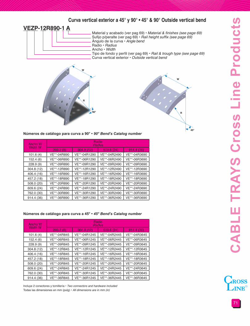
Curva horizontal a 45° y 90° • 45° & 90° Horizontal bend
VHZP-12R890-1 AMaterial y acabado (ver pag 69) • Material & finishes (see page 69)Sufijo p/peralte (ver pag 69) • Rail height suffix (see page 69)Ángulo de la curva • Angle bendRadio • RadiusAncho • WidthTipo de fondo y perfil (ver pag 69) • Rail & trough type (see page 69)Curva horizontal • Horizontal bend
Números de catálogo para curva a 90° • 90° Bend’s Catalog number
Números de catálogo para curva a 45° • 45° Bend’s Catalog number
Ancho WWidth W
RadioRadius
203.2 (8) 304.8 (12) 609.6 (24) 914.4 (36)101.6 (4) VH**-04R890 VH**-04R1290 VH**-04R2490 VH**-04R3690152.4 (6) VH**-06R890 VH**-06R1290 VH**-06R2490 VH**-06R3690228.9 (9) VH**-09R890 VH**-09R1290 VH**-09R2490 VH**-09R3690
304.8 (12) VH**-12R890 VH**-12R1290 VH**-12R2490 VH**-12R3690406.4 (16) VH**-16R890 VH**-16R1290 VH**-16R2490 VH**-16R3690457.2 (18) VH**-18R890 VH**-18R1290 VH**-18R2490 VH**-18R3690508.0 (20) VH**-20R890 VH**-20R1290 VH**-20R2490 VH**-20R3690609.6 (24) VH**-24R890 VH**-24R1290 VH**-24R2490 VH**-24R3690762.0 (30) VH**-30R890 VH**-30R1290 VH**-30R2490 VH**-30R3690914.4 (36) VH**-36R890 VH**-36R1290 VH**-36R2490 VH**-36R3690
Ancho WWidth W
RadioRadius
203.2 (8) 304.8 (12) 609.6 (24) 914.4 (36)101.6 (4) VH**-04R845 VH**-04R1245 VH**-04R2445 VH**-04R3645152.4 (6) VH**-06R845 VH**-06R1245 VH**-06R2445 VH**-06R3645228.9 (9) VH**-09R845 VH**-09R1245 VH**-09R2445 VH**-09R3645
304.8 (12) VH**-12R845 VH**-12R1245 VH**-12R2445 VH**-12R3645406.4 (16) VH**-16R845 VH**-16R1245 VH**-16R2445 VH**-16R3645457.2 (18) VH**-18R845 VH**-18R1245 VH**-18R2445 VH**-18R3645508.0 (20) VH**-20R845 VH**-20R1245 VH**-20R2445 VH**-20R3645609.6 (24) VH**-24R845 VH**-24R1245 VH**-24R2445 VH**-24R3645762.0 (30) VH**-30R845 VH**-30R1245 VH**-30R2445 VH**-30R3645914.4 (36) VH**-36R845 VH**-36R1245 VH**-36R2445 VH**-36R3645
Todas las dimensiones en mm (pulg) • All dimensions are in mm (in)Incluye 2 conectores y tornillería • Two connectors and hardware included
WWR
R
90°
45°
71
CA
BLE
TR
AYS
Cro
ss L
ine
Pro
duct
sCurva vertical exterior a 45° y 90° • 45° & 90° Outside vertical bend
VEZP-12R890-1 A Material y acabado (ver pag 69) • Material & finishes (see page 69)Sufijo p/peralte (ver pag 69) • Rail height suffix (see page 69)Ángulo de la curva • Angle bendRadio • RadiusAncho • WidthTipo de fondo y perfil (ver pag 69) • Rail & trough type (see page 69)Curva vertical exterior • Outside vertical bend
Números de catálogo para curva a 90° • 90° Bend’s Catalog number
Números de catálogo para curva a 45° • 45° Bend’s Catalog number
Ancho WWidth W
RadioRadius
203.2 (8) 304.8 (12) 609.6 (24) 914.4 (36)101.6 (4) VE**-04R890 VE**-04R1290 VE**-04R2490 VE**-04R3690152.4 (6) VE**-06R890 VE**-06R1290 VE**-06R2490 VE**-06R3690228.9 (9) VE**-09R890 VE**-09R1290 VE**-09R2490 VE**-09R3690
304.8 (12) VE**-12R890 VE**-12R1290 VE**-12R2490 VE**-12R3690406.4 (16) VE**-16R890 VE**-16R1290 VE**-16R2490 VE**-16R3690457.2 (18) VE**-18R890 VE**-18R1290 VE**-18R2490 VE**-18R3690508.0 (20) VE**-20R890 VE**-20R1290 VE**-20R2490 VE**-20R3690609.6 (24) VE**-24R890 VE**-24R1290 VE**-24R2490 VE**-24R3690762.0 (30) VE**-30R890 VE**-30R1290 VE**-30R2490 VE**-30R3690914.4 (36) VE**-36R890 VE**-36R1290 VE**-36R2490 VE**-36R3690
Ancho WWidth W
RadioRadius
203.2 (8) 304.8 (12) 609.6 (24) 914.4 (36)101.6 (4) VE**-04R845 VE**-04R1245 VE**-04R2445 VE**-04R3645152.4 (6) VE**-06R845 VE**-06R1245 VE**-06R2445 VE**-06R3645228.9 (9) VE**-09R845 VE**-09R1245 VE**-09R2445 VE**-09R3645
304.8 (12) VE**-12R845 VE**-12R1245 VE**-12R2445 VE**-12R3645406.4 (16) VE**-16R845 VE**-16R1245 VE**-16R2445 VE**-16R3645457.2 (18) VE**-18R845 VE**-18R1245 VE**-18R2445 VE**-18R3645508.0 (20) VE**-20R845 VE**-20R1245 VE**-20R2445 VE**-20R3645609.6 (24) VE**-24R845 VE**-24R1245 VE**-24R2445 VE**-24R3645762.0 (30) VE**-30R845 VE**-30R1245 VE**-30R2445 VE**-30R3645914.4 (36) VE**-36R845 VE**-36R1245 VE**-36R2445 VE**-36R3645
Todas las dimensiones en mm (pulg) • All dimensions are in mm (in)Incluye 2 conectores y tornillería • Two connectors and hardware included
W
W
R
R90°
45°

CH
AR
OLA
S P
rodu
ctos
Cro
ss L
ine
72
Curva vertical interior a 45° y 90° • 45° & 90° Inside vertical bend
VIZP-12R890-1 A Material y acabado (ver pag 69) • Material & finishes (see page 69)Sufijo p/peralte (ver pag 69) • Rail height suffix (see page 69)Ángulo de la curva • Angle bendRadio • RadiusAncho • WidthTipo de fondo y perfil (ver pag 69) • Rail & trough type (see page 69)Curva vertical interior • Inside vertical bend
Números de catálogo para curva a 90° • 90° Bend’s Catalog number
Números de catálogo para curva a 45° • 45° Bend’s Catalog number
Ancho WWidth W
RadioRadius
203.2 (8) 304.8 (12) 609.6 (24) 914.4 (36)101.6 (4) VI**-04R890 VI**-04R1290 VI**-04R2490 VI**-04R3690152.4 (6) VI**-06R890 VI**-06R1290 VI**-06R2490 VI**-06R3690228.9 (9) VI**-09R890 VI**-09R1290 VI**-09R2490 VI**-09R3690
304.8 (12) VI**-12R890 VI**-12R1290 VI**-12R2490 VI**-12R3690406.4 (16) VI**-16R890 VI**-16R1290 VI**-16R2490 VI**-16R3690457.2 (18) VI**-18R890 VI**-18R1290 VI**-18R2490 VI**-18R3690508.0 (20) VI**-20R890 VI**-20R1290 VI**-20R2490 VI**-20R3690609.6 (24) VI**-24R890 VI**-24R1290 VI**-24R2490 VI**-24R3690762.0 (30) VI**-30R890 VI**-30R1290 VI**-30R2490 VI**-30R3690914.4 (36) VI**-36R890 VI**-36R1290 VI**-36R2490 VI**-36R3690
Ancho WWidth W
RadioRadius
203.2 (8) 304.8 (12) 609.6 (24) 914.4 (36)101.6 (4) VI**-04R845 VI**-04R1245 VI**-04R2445 VI**-04R3645152.4 (6) VI**-06R845 VI**-06R1245 VI**-06R2445 VI**-06R3645228.9 (9) VI**-09R845 VI**-09R1245 VI**-09R2445 VI**-09R3645
304.8 (12) VI**-12R845 VI**-12R1245 VI**-12R2445 VI**-12R3645406.4 (16) VI**-16R845 VI**-16R1245 VI**-16R2445 VI**-16R3645457.2 (18) VI**-18R845 VI**-18R1245 VI**-18R2445 VI**-18R3645508.0 (20) VI**-20R845 VI**-20R1245 VI**-20R2445 VI**-20R3645609.6 (24) VI**-24R845 VI**-24R1245 VI**-24R2445 VI**-24R3645762.0 (30) VI**-30R845 VI**-30R1245 VI**-30R2445 VI**-30R3645914.4 (36) VI**-36R845 VI**-36R1245 VI**-36R2445 VI**-36R3645
Todas las dimensiones en mm (pulg) • All dimensions are in mm (in)Incluye 2 conectores y tornillería • Two connectors and hardware included
W
W
R
R90°
45°

73
CA
BLE
TR
AYS
Cro
ss L
ine
Pro
duct
s“T” Horizontal • Horizontal tee
THZL-12R8-1 AMaterial y acabado (ver pag 69) • Material & finishes (see page 69)Sufijo p/peralte (ver pag 69) • Rail height suffix (see page 69)Radio • RadiusAncho • WidthTipo de fondo y perfil (ver pag 69) • Rail & trough type (see page 69)“T” horizontal • Horizontal “T”
Ancho WWidth W
Radio 203.2 Solo radialRadius (8) Radial only
Radio 304.8Radius (12)
No. de catálogoCatalog number A B No. de catálogo
Catalog number A B
101.6 (4) TH**-04R8 731 (28.78) 416 (16.39) TH**-04R12 864 (34) 518 (20.39)152.4 (6) TH**-06R8 782 (30.78) 467 (18.39) TH**-06R12 914 (36) 569 (22.39)228.9 (9) TH**-09R8 585 (23.03) 543 (21.39) TH**-09R12 991 (39) 645 (25.39)
304.8 (12) TH**-12R8 934 (36.78) 619 (24.39) TH**-12R12 1137 (44.78) 721 (28.39)406.4 (16) TH**-16R8 1036 (40.78) 721 (28.39) TH**-16R12 1239 (48.78) 823 (32.39)457.2 (18) TH**-18R8 1086 (42.78) 772 (30.39) TH**-18R12 1290 (50.78) 873 (34.39)508.0 (20) TH**-20R8 1137 (44.78) 823 (32.39) TH**-20R12 1341 (52.78) 924 (36.39)609.6 (24) TH**-24R8 1239 (48.78) 924 (36.39) TH**-24R12 1442 (56.78) 1026 (40.39)762.0 (30) TH**-30R8 1391 (54.78) 1077 (42.39) TH**-30R12 1595 (62.78) 1178 (46.39)914.4 (36) TH**-36R8 1543 (60.78) 1229 (48.39) TH**-36R12 1747 (68.78) 1331 (52.39)
Ancho WWidth W
Radio 609.6Radius (24)
Radio 914.4Radius (36)
No. de catálogoCatalog number A B No. de catálogo
Catalog number A B
101.6 (4) TH**-04R24 1544 (60.78) 823 (32.39) TH**-04R36 2153 (84.78) 1127 (44.39)152.4 (6) TH**-06R24 1595 (62.78) 873 (34.39) TH**-06R36 2204 (86.78) 1178 (46.39)228.9 (9) TH**-09R24 1671 (65.78) 950 (37.39) TH**-09R36 2280 (89.78) 1254 (49.39)
304.8 (12) TH**-12R24 1747 (68.78) 1030 (40.39) TH**-12R36 2357 (92.78) 1331 (52.39)406.4 (16) TH**-16R24 1849 (72.78) 1127 (44.39) TH**-16R36 2458 (96.78) 1432 (56.39)457.2 (18) TH**-18R24 1899 (74.78) 1178 (46.39) TH**-18R36 2509 (98.78) 1483 (58.39)508.0 (20) TH**-20R24 1950 (76.78) 1229 (48.39) TH**-20R36 2560 (100.78) 1534 (60.39)609.6 (24) TH**-24R24 2052 (80.78) 1331 (52.39) TH**-24R36 2661 (104.78) 1635 (64.39)762.0 (30) TH**-30R24 2204 (86.78) 1483 (58.39) TH**-30R36 2814 (110.78) 1788 (70.39)914.4 (36) TH**-36R24 2357 (92.78) 1635 (64.39) TH**-36R36 2966 (116.78) 1940 (76.39)
Todas las dimensiones en mm (pulg) • All dimensions are in mm (in)Incluye 2 conectores y tornillería • Two connectors and hardware included
WW
B
A
R

CH
AR
OLA
S P
rodu
ctos
Cro
ss L
ine
74
“X” Horizontal • Horizontal cross
XHZP-12R8-1 AMaterial y acabado (ver pag 69) • Material & finishes (see page 69)Sufijo p/peralte (ver pag 69) • Rail height suffix (see page 69)Radio • RadiusAncho • WidthTipo de fondo y perfil (ver pag 69) • Rail & trough type (see page 69)“X” Horizontal • Horizontal cross
Ancho WWidth W
Radio 203.2 Solo radialRadius (8) Radial only
Radio 304.8Radius (12)
No. de catálogoCatalog number A No. de catálogo
Catalog number A
101.6 (4) XH**-04R8 731 (28.78) XH**-04R12 864 (34)152.4 (6) XH**-06R8 782 (30.78) XH**-06R12 914 (36)228.9 (9) XH**-09R8 585 (23.03) XH**-09R12 991 (39)
304.8 (12) XH**-12R8 934 (36.78) XH**-12R12 1137 (44.78)406.4 (16) XH**-16R8 1036 (40.78) XH**-16R12 1239 (48.78)457.2 (18) XH**-18R8 1086 (42.78) XH**-18R12 1290 (50.78)508.0 (20) XH**-20R8 1137 (44.78) XH**-20R12 1341 (52.78)609.6 (24) XH**-24R8 1239 (48.78) XH**-24R12 1442 (56.78)762.0 (30) XH**-30R8 1391 (54.78) XH**-30R12 1595 (62.78)914.4 (36) XH**-36R8 1543 (60.78) XH**-36R12 1747 (68.78)
Ancho WWidth W
Radio 609.6Radius (24)
Radio 914.4Radius (36)
No. de catálogoCatalog number A No. de catálogo
Catalog number A
101.6 (4) XH**-04R24 1544 (60.78) XH**-04R36 2153 (84.78)152.4 (6) XH**-06R24 1595 (62.78) XH**-06R36 2204 (86.78)228.9 (9) XH**-09R24 1671 (65.78) XH**-09R36 2280 (89.78)
304.8 (12) XH**-12R24 1747 (68.78) XH**-12R36 2357 (92.78)406.4 (16) XH**-16R24 1849 (72.78) XH**-16R36 2458 (96.78)457.2 (18) XH**-18R24 1899 (74.78) XH**-18R36 2509 (98.78)508.0 (20) XH**-20R24 1950 (76.78) XH**-20R36 2560 (100.78)609.6 (24) XH**-24R24 2052 (80.78) XH**-24R36 2661 (104.78)762.0 (30) XH**-30R24 2204 (86.78) XH**-30R36 2814 (110.78)914.4 (36) XH**-36R24 2357 (92.78) XH**-36R36 2966 (116.78)
Todas las dimensiones en mm (pulg) • All dimensions are in mm (in)Incluye 2 conectores y tornillería • Two connectors and hardware included
W W
A
AR

75
CA
BLE
TR
AYS
Cro
ss L
ine
Pro
duct
s“T” Vertical • Vertical tee
TVZP-12R8-1 AMaterial y acabado (ver pag 69) • Material & finishes (see page 69)Sufijo p/peralte (ver pag 69) • Rail height suffix (see page 69)Radio • RadiusAncho • WidthTipo de fondo y perfil (ver pag 69) • Rail & trough type (see page 69)“T” vertical • Vertical “T”
Ancho WWidth W
RadioRadius
203.2 (8) 304.8 (12) 609.6 (24) 914.4 (36)101.6 (4) TV**-04R8 TV**-04R12 TV**-04R24 TV**-04R36152.4 (6) TV**-06R8 TV**-06R12 TV**-06R24 TV**-06R36228.9 (9) TV**-09R8 TV**-09R12 TV**-09R24 TV**-09R36
304.8 (12) TV**-12R8 TV**-12R12 TV**-12R24 TV**-12R36406.4 (16) TV**-16R8 TV**-16R12 TV**-16R24 TV**-16R36457.2 (18) TV**-18R8 TV**-18R12 TV**-18R24 TV**-18R36508.0 (20) TV**-20R8 TV**-20R12 TV**-20R24 TV**-20R36609.6 (24) TV**-24R8 TV**-24R12 TV**-24R24 TV**-24R36762.0 (30) TV**-30R8 TV**-30R12 TV**-30R24 TV**-30R36914.4 (36) TV**-36R8 TV**-36R12 TV**-36R24 TV**-36R36
Sufijo p/peralteHeight rail suffix
Radio • Radius203.2 (8) 304.8 (12) 609.6 (24) 914.4 (36)
A B A B A B A B1 489 (19.25) 286 (11.25) 692 (27.25) 387 (15.25) 1302 (51.25) 692 (27.25) 1911 (75.25) 997 (39.25)2 508 (20) 305 (12) 711 (28) 406 (16) 1321 (52) 711 (28) 1930 (76) 1016 (40)3 521 (20.5) 318 (12.5) 724 (28.5) 419 (16.5) 1334 (52.5) 724 (28.5) 1943 (76.5) 1029 (40.5)5 533 (21) 330 (13) 737 (29) 432 (17) 1346 (53) 737 (29) 1956 (77) 1041 (41)6 559 (22) 356 (14) 762 (30) 457 (18) 1372 (54) 762 (30) 1981 (78) 1067 (42)
Todas las dimensiones en mm (pulg) • All dimensions are in mm (in)Incluye 2 conectores y tornillería • Two connectors and hardware included
W
B
A
R

CH
AR
OLA
S P
rodu
ctos
Cro
ss L
ine
76
Curva horizontal ajustable • Horizontal adjustable bend
Derivación horizontal a 45° • 45° Horizontal wye branch
CAZP-12-1 A
DY * ZP-12-1 A
Material y acabado (ver pag 69) • Material & finishes (see page 69)Sufijo p/peralte (ver pag 69) • Rail height suffix (see page 69)Ancho • WidthTipo de fondo y perfil (ver pag 69) • Rail & trough type (see page 69)Curva horizontal ajustable • Horizontal adjustable bend
Material y acabado (ver pag 69) • Material & finishes (see page 69)Sufijo p/peralte (ver pag 69) • Rail height suffix (see page 69)Ancho • WidthTipo de fondo y perfil (ver pag 69) • Rail & trough type (see page 69)Colocar “D” para derecha o “I” izquierda • Add “D” for right or “I” for leftDerivación horizontal a 45° • 45° Horizontal wye branch
Ancho WWidth W
No. de catálogoCatalog number
101.6 (4) CA**-04152.4 (6) CA**-06228.9 (9) CA**-09
304.8 (12) CA**-12406.4 (16) CA**-16457.2 (18) CA**-18508.0 (20) CA**-20609.6 (24) CA**-24762.0 (30) CA**-30914.4 (36) CA**-36
Ancho WWidth W
No. de catálogoCatalog number A
101.6 (4) DY**-04 463 (18.2)152.4 (6) DY**-06 534 (21)228.9 (9) DY**-09 642 (25.3)
304.8 (12) DY**-12 750 (29.5)406.4 (16) DY**-16 894 (35.2)457.2 (18) DY**-18 966 (38)508.0 (20) DY**-20 1037 (40.8)609.6 (24) DY**-24 1181 (46.5)762.0 (30) DY**-30 1396 (55)914.4 (36) DY**-36 1612 (63.5)
Todas las dimensiones en mm (pulg) • All dimensions are in mm (in)
No incluye cintas conductoras • Bonding jumpers not includedTodas las dimensiones en mm (pulg) • All dimensions are in mm (in)
Incluye 2 conectores y tornillería • Two connectors and hardware included
Incluye 2 conectores y tornillería • Two connectors and hardware included
0° A 90°
W
152 (6)
W
A
45°

77
CA
BLE
TR
AYS
Cro
ss L
ine
Pro
duct
s
RectaStraight
DerechaRight
IzquierdaLeft
W2W2
W2
W1 W1W1
457 (18) 457 (18) 457 (18)
RL ZP-1209-1 AReducciones • Reducers
Material y acabado • Material & finishesSufijo p/peralte (ver pag 69) • Rail height suffix (see page 69)Ancho menor • Smaller widthAncho mayor • Larger widthPerfil tipo (ver pag 69) • Rail type (see page 69)Reducción • ReducerRL = Recta • StraightRLD = Derecha • RightRLI = Izquierda • Left
Todas las dimensiones en mm (pulg) • All dimensions are in mm (in)Incluye 2 conectores y tornillería • Two connectors and hardware included
N° de catálogo reducciones rectas • Straight reducer catalog number
N° de catálogo reducciones derechas • Right reducer catalog number
N° de catálogo reducciones izquierdas • Left reducer catalog number
Ancho W1Width W1
Ancho menor W2Smaller width W2
101.6 (4) 152.4 (6) 228.9 (9) 304.8 (12) 406.4 (16) 457.2 (18) 508.0 (20) 609.6 (24) 762.0 (30)152.4 (6) RL**-0604228.9 (9) RL**-0904 RL**-0906
304.8 (12) RL**-1204 RL**-1206 RL**-1209406.4 (16) RL**-1604 RL**-1606 RL**-1609 RL**-1612457.2 (18) RL**-1804 RL**-1806 RL**-1809 RL**-1812 RL**-1816508.0 (20) RL**-2004 RL**-2006 RL**-2009 RL**-2012 RL**-2016 RL**-2018609.6 (24) RL**-2404 RL**-2406 RL**-2409 RL**-2412 RL**-2416 RL**-2418 RL**-2420762.0 (30) RL**-3004 RL**-3006 RL**-3009 RL**-3012 RL**-3016 RL**-3018 RL**-3020 RL**-3024914.4 (36) RL**-3604 RL**-3606 RL**-3609 RL**-3612 RL**-3616 RL**-3618 RL**-3620 RL**-3624 RL**-3630
Ancho W1Width W1
Ancho menor W2Smaller width W2
101.6 (4) 152.4 (6) 228.9 (9) 304.8 (12) 406.4 (16) 457.2 (18) 508.0 (20) 609.6 (24) 762.0 (30)152.4 (6) RLD**-0604228.9 (9) RLD**-0904 RLD**-0906
304.8 (12) RLD**-1204 RLD**-1206 RLD**-1209406.4 (16) RLD**-1604 RLD**-1606 RLD**-1609 RLD**-1612457.2 (18) RLD**-1804 RLD**-1806 RLD**-1809 RLD**-1812 RLD**-1816508.0 (20) RLD**-2004 RLD**-2006 RLD**-2009 RLD**-2012 RLD**-2016 RLD**-2018609.6 (24) RLD**-2404 RLD**-2406 RLD**-2409 RLD**-2412 RLD**-2416 RLD**-2418 RLD**-2420762.0 (30) RLD**-3004 RLD**-3006 RLD**-3009 RLD**-3012 RLD**-3016 RLD**-3018 RLD**-3020 RLD**-3024914.4 (36) RLD**-3604 RLD**-3606 RLD**-3609 RLD**-3612 RLD**-3616 RLD**-3618 RLD**-3620 RLD**-3624 RLD**-3630
Ancho W1Width W1
Ancho menor W2Smaller width W2
101.6 (4) 152.4 (6) 228.9 (9) 304.8 (12) 406.4 (16) 457.2 (18) 508.0 (20) 609.6 (24) 762.0 (30)152.4 (6) RLI**-0604228.9 (9) RLI**-0904 RLI**-0906
304.8 (12) RLI**-1204 RLI**-1206 RLI**-1209406.4 (16) RLI**-1604 RLI**-1606 RLI**-1609 RLI**-1612457.2 (18) RLI**-1804 RLI**-1806 RLI**-1809 RLI**-1812 RLI**-1816508.0 (20) RLI**-2004 RLI**-2006 RLI**-2009 RLI**-2012 RLI**-2016 RLI**-2018609.6 (24) RLI**-2404 RLI**-2406 RLI**-2409 RLI**-2412 RLI**-2416 RLI**-2418 RLI**-2420762.0 (30) RLI**-3004 RLI**-3006 RLI**-3009 RLI**-3012 RLI**-3016 RLI**-3018 RLI**-3020 RLI**-3024914.4 (36) RLI**-3604 RLI**-3606 RLI**-3609 RLI**-3612 RLI**-3616 RLI**-3618 RLI**-3620 RLI**-3624 RLI**-3630

CH
AR
OLA
S P
rodu
ctos
Cro
ss L
ine
78
Todas las dimensiones en mm (pulg) • All dimensions are in mm (in)
Todas las dimensiones en mm (pulg) • All dimensions are in mm (in)
Todas las dimensiones en mm (pulg) • All dimensions are in mm (in)
Todas las dimensiones en mm (pulg) • All dimensions are in mm (in)Tornillería incluida • Hardware included
Tornillería incluida • Hardware included
Tornillería incluida • Hardware included
Tornillería incluida • Hardware included
Aplicable solo para productos perfil tipo Z • Use only with products Z rail side form
Conector tipo “Z” • “Z” Form splice plate
Conector recto • Straight splice plate
Conector tipo “L” • “L” Form splice plate
Conector de expansión • Expansion connector
AZ-4.5 1 A
AR-4.5 1 A
AL-4.5 1 A
AE-1 A
Material y acabado (ver pag 58) • Material & finishes (see page 58)Sufijo p/peralte (ver pag 59) • Rail height suffix (see page 59)Largo en pulg. • Length in inchesConector tipo z • Z form connector
Material y acabado (ver pag 58) • Material & finishes (see page 58)Sufijo p/peralte (ver pag 59) • Rail height suffix (see page 59)Largo en pulg. • Length in inchesConector recto • Straight connector
Material y acabado (ver pag 58) • Material & finishes (see page 58)Sufijo p/peralte (ver pag 59) • Rail height suffix (see page 59)Largo en pulg. • Length in inchesConector tipo L • L form connector
Material y acabado (ver pag 58) • Material & finishes (see page 58)Sufijo p/peralte (ver pag 59) • Rail height suffix (see page 59)Conector de expansión • Expansion connector
PeralteRailheight
114 (4.5)
114 (4.5)
157 (6.18)
114 (4.5)
Sección 4.3Accesorios de ensamble
para charolas tipoescalera y fondo sólido
Section 4.3Assembly fittings for
ladder and solid trough type cable tray systems.

79
CA
BLE
TR
AYS
Cro
ss L
ine
Pro
duct
sElevador ajustable • Vertical adjustable connector
Conector horizontal ajustable • Horizontal adjustable connector
Conector reductor • Reducer connector
EA-1 A
AH-1 A
ARR - 3 - 1 A
Material y acabado (ver pag 58) • Material & finishes (see page 58)Sufijo p/peralte (ver pag 59) • Rail height suffix (see page 59)Elevador ajustable • Vertical adjustable connector
Material y acabado (ver pag 58) • Material & finishes (see page 58)Sufijo p/peralte (ver pag 59) • Rail height suffix (see page 59)Conector horizontal ajustable • Horizontal adjustable connector
Material y acabado (ver pag 58) • Material & finishes (see page 58)Sufijo p/peralte (ver pag 59) • Rail height suffix (see page 59)Diferencia de anchos ver tabla • Width difference see tableConector reductor • Reducer connector
208 (8.19)
208 (8.19)
104 (4.09)
104 (4.09)
104 (4.09)
L
No incluye cintas conductoras • Bonding jumpers not included
No incluye cintas conductoras • Bonding jumpers not included
Tornillería incluida • Hardware included
Medidas de reducción de línea.La reducción se puede fabricar en cualquier medida solicitadaTornillería incluida • Hardware included
Todas las dimensiones en mm (pulg) • All dimensions are in mm (in)
No. de catálogoCatalog number
Lmm (pulg)
ARR-1 76.2 (3")ARR-2 152.4(6")ARR-3 228.6(9")ARR-4 304.8(12")ARR-5 381.0(15")ARR-6 457.2(18")ARR-7 609.6(24")ARR-8 762.0(30")
CH
AR
OLA
S P
rodu
ctos
Cro
ss L
ine
80
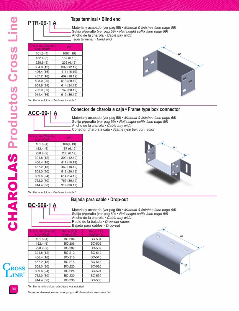
Tapa terminal • Blind end
Conector de charola a caja • Frame type box connector
Bajada para cable • Drop-out
PTR-09-1 A
ACC-09-1 A
BC-509-1 A
Material y acabado (ver pag 58) • Material & finishes (see page 58)Sufijo p/peralte (ver pag 59) • Rail height suffix (see page 59)Ancho de la charola • Cable tray widthTapa terminal • Blind end
Material y acabado (ver pag 58) • Material & finishes (see page 58)Sufijo p/peralte (ver pag 59) • Rail height suffix (see page 59)Ancho de la charola • Cable tray widthConector charola a caja • Frame type box connector
Material y acabado (ver pag 58) • Material & finishes (see page 58)Sufijo p/peralte (ver pag 59) • Rail height suffix (see page 59)Ancho de la charola • Cable tray widthRadio de la bajada • Drop-out radiusBajada para cables • Drop-out
W1
W1
W1
R
Tornillería incluida • Hardware included
Tornillería incluida • Hardware included
Tornillería no incluida • Hardware not included
Todas las dimensiones en mm (pulg) • All dimensions are in mm (in)
Ancho de CharolaTray Width W1
101.6 (4) 106(4.19)152.4 (6) 157 (6.19)228.9 (9) 233 (6.19)
304.8 (12) 309 (12.19)406.4 (16) 411 (16.19)457.2 (18) 462 (18.19)508.0 (20) 513 (20.19)609.6 (24) 614 (24.19)762.0 (30) 767 (30.19)914.4 (36) 919 (36.19)
Ancho de CharolaTray Width W1
101.6 (4) 106(4.19)152.4 (6) 157 (6.19)228.9 (9) 233 (6.19)
304.8 (12) 309 (12.19)406.4 (16) 411 (16.19)457.2 (18) 462 (18.19)508.0 (20) 513 (20.19)609.6 (24) 614 (24.19)762.0 (30) 767 (30.19)914.4 (36) 919 (36.19)
Ancho de CharolaTray Width
Radio 50.8Radius (2)
Radio 127Radius (5)
101.6 (4) BC-204 BC-504152.4 (6) BC-206 BC-506228.9 (9) BC-209 BC-509
304.8 (12) BC-212 BC-512406.4 (16) BC-216 BC-516457.2 (18) BC-218 BC-518508.0 (20) BC-220 BC-520609.6 (24) BC-224 BC-524762.0 (30) BC-230 BC-530914.4 (36) BC-236 BC-536

81
CA
BLE
TR
AYS
Cro
ss L
ine
Pro
duct
sBarreras separadoras tramo recto • Straight divider strip
Barreras separadoras accesorios horizontales • Horizontal fittings divider strip
Barreras separadoras accesorios verticales • Vertical fittings divider strip
Cintas conductoras • Bonding jumpers
BSCH-1 A 3.05m
BSH-72-1 A
BSVEC-04R08901 A
Longitud de la charola en metros (3.05m y 3.66m) • Cable tray length in meters (3.05m and 3.66m)Material y acabado (ver pag 58) • Material & finishes (see page 58)Sufijo p/peralte (ver pag 58) • Rail height suffix (see page 58)Barrera separadora para tramo recto • Straight divider strip
Material y acabado (ver pag 58) • Material & finishes (see page 58)Sufijo p/peralte (ver pag 58) • Rail height suffix (see page 58)Longitud de la barrera en pulgadas (48” y 72”) • Divider strip length in inches (48” and 72”)Barrera separadora para curva horizontal • Horizontal fitting divider strip
No de catálogo de la curva a la que se colocara la barrera.Catalog number of the vertical fittingBarrera separadora para curva vertical • Vertical fitting divider strip
Incluye 5 clemas Clamp-112 con tornillería • Five hold down Clamp-112 and hardware included
Incluye 3 clemas Clamp-112 con tornillería • Three hold down Clamp-112 and hardware included
Para su selección y aplicación consulte NOM-001-SEDE-2012 artículos 318-6A y 318-7, además de NEMA VE-2For application and selection, see NEC CODE 318-6A & 318-7, also NEMA VE-2
Incluye clemas Clamp-112 con tornillería • Hold down Clamp-112 and hardware included
Todas las dimensiones en mm (pulg) • All dimensions are in mm (in)
No de catálogoCatalog number
CapacidadCapacity
CC-99NI 600 AMP. MAX.CC-9940 1600 AMP. MAX

CH
AR
OLA
S P
rodu
ctos
Cro
ss L
ine
82
Tapas para tramo recto • Straight covers
Clips de sujeción para tapas • Cover clamps
TRCV-CHCP-12-1A
CST-14-GI
CSTSC-14-1GI
No de catálogo de la pieza a cubrir • Covered product catalog numberTipo de tapa • Cover type
Material y acabado (ver pag 58) • Material & finishes (see page 58)Clip normal • Standard clamp
Material y acabado (ver pag 58) • Material & finishes (see page 58)Sufijo p/peralte (ver pag 58) • Rail height suffix (see page 58)Clip largo • Large clamp
Tapa recta tipo “TR”Flat cover “TR” type
Tapa sombrero tipo “TSS”Domed cover “TSS” type
Tapa con ceja tipo “TRC”Flanged cover “TRC” type
Tapa recta con ventilación tipo “TRV”Flat vented cover “TRV” type
Tapa a dos aguas tipo “TA”Peaked cover “TA” type
Tapa con ceja con ventilación tipo “TRCVFlanged and vented cover “TRCV” type
Todas las dimensiones en mm (pulg) • All dimensions are in mm (in)
Las tapas se surten en juegos de 3 tapas de 1219 mm (4 ft) e incluyen 12 clips de sujeción
Para otras longitudes consulte nuestro departamento de ingeniería
Las tapas para accesorios solo se fabrican en tipo recto e incluyen clips necesarios.
Covers are supplied in sets of 3 covers of 1219 mm (4 ft) 12 cover clamps are included
For other lengths or designs please consult our technical department
Only flat type is supplied for fitting covers and cover clamps needed are included
Para charolas perfiles tipo “Z”, “C” afuera, e “I”For products with rail type “Z”, “C” flanged out, & “I”
Para charolas perfiles tipo “C” For products with rail type “C”
Las tapas para charola tipo fondo sólido se surten en juegos de 2 tapas de 1525 mm (5 ft) e incluyen 8 clipsSolid trough type cable tray covers are supplied in sets of 2 covers of 1525 mm (5 ft) 8 cover clamps are included.

83
CA
BLE
TR
AYS
Cro
ss L
ine
Pro
duct
sSección 4.4Accesorios de montaje
Section 4.4Supports and brackets
Ménsula para montaje en pared • Wall cantilever bracket
MPPI-09-GIMaterial y acabado • Material & finishes Ancho de la charola • Cable tray widthColocar esta letra para charolas con perfil tipo “C” hacia fuera, e “I”Use this letter for “C” flange out & “I” rail traysMénsula para pared • Wall supported bracket
Ancho de charolaTray width A No de catálogo
Catalog number L No de catálogoCatalog number L Carga soportada
Load capacity101.6 (4)
120 (4.75)
MPP-04 127 (5) MPPI-04 152 (6) 705 kg (1550 lb)152.4 (6) MPP-06 178 (7) MPPI-06 203 (8) 665 kg (1460 lb)228.9 (9) MPP-09 254 (10) MPPI-09 279 (11) 645 kg (1420 lb)
304.8 (12) MPP-12 330 (13) MPPI-12 356 (14) 550 kg (1215 lb)406.4 (16)
158 (6.22)
MPP-16 432 (17) MPPI-16 457 (18) 505 kg (1115 lb)457.2 (18) MPP-18 483 (19) MPPI-18 508 (20) 450 kg (990 lb)508.0 (20) MPP-20 533 (21) MPPI-20 559 (22) 385 kg (850 lb)609.6 (24) MPP-24 635 (25) MPPI-24 660 (26) 325 kg (717 lb)762.0 (30) MPP-30 787 (31) MPPI-30 813 (32) 275 kg (607 lb)914.4 (36) MPP-36 940 (37) MPPI-36 965 (38) 225 kg (496 lb)
Para perfil tipo Z, C, I (ligero)(ver pag 58)
For Z, C, I rail type(see page 58)
Para perfil tipo “C” hacia afuera, e “I” (pesado)
(ver pag 58)For “C” flanged out & “I” rail
type (see page 58)
No incluye tornillería ni sistemas de fijación. • Hardware, clamps or anchoring system are not included
Materiales y acabados:GI: Acero al carbón galvanizado por inmersión en caliente GE: Acero al carbón galvanizado electrolítico T: Acero al carbón tropicalizadoPVC: Acero al carbón recubierto con PVCAI: Acero inoxidable Para materiales y acabados no indicados consulte nuestro departamento de ingeniería Todas las dimensiones en mm (pulg)
La carga soportada muestra la capacidad de la ménsula, CROSS LINE no se hace responsable de fallas atribuibles a los sistemas de anclaje o el sustrato de apoyo.
Las cargas soportadas están basadas en un factor de seguridad de 2.5.
The load shown indicates bracket’s load capacity. CROSS LINE is not responsible for failures caused by the anchoring system or wall materials.
Load capacities are based in a 2.5 safety factor.
Materials&finishes:GI: Hot dip galvanized steel GE: Electro galvanized steel T: Chromium-zinc coated steelPVC: PVC coated steelAI: Stainless steelFor materials and finishes not shown please consult our technical departmentAll dimensions are in mm (in)
14.3 (9/16)
L
A

CH
AR
OLA
S P
rodu
ctos
Cro
ss L
ine
84
Ménsula para montaje en canal • Channel cantilever bracket
Canal vertical • Vertical “C” channel
MCI-09-GI
CVPP-120-GI
Material y acabado (ver pag 83) • Material & finishes (see page 83)Ancho de la charola • Cable tray widthColocar esta letra para charolas con perfil tipo “C” hacia fuera, e “I”Use this letter for “C” flange out & “I” rail traysMénsula para canal • Channel cantilever bracket
Material y acabado (ver pag 83) • Material & finishes (see page 83)Longitud del canal en pulgadas • Channel length in inchesColocar esta letra en canales con altura de 19 mm (3/4)Use this letter for channels with 19 (3/4) heightCanal vertical • Vertical “C” channel
Ancho de charolaTray width A No de catálogo
Catalog number L No de catálogoCatalog number L Carga soportada
Load capacity101.6 (4)
79 (3.1)
MC-04 127 (5) MCI-04 152 (6) 345 kg (762 lb)152.4 (6) MC-06 178 (7) MCI-06 203 (8) 325 kg (717 lb)228.9 (9) MC-09 254 (10) MCI-09 279 (11) 315 kg (695 lb)
304.8 (12) MC-12 330 (13) MCI-12 356 (14) 270 kg (596 lb)406.4 (16)
158 (6.22)
MC-16 432 (17) MCI-16 457 (18) 245 kg (540 lb)457.2 (18) MC-18 483 (19) MCI-18 508 (20) 220 kg (485 lb)508.0 (20) MC-20 533 (21) MCI-20 559 (22) 190 kg (420 lb)609.6 (24) MC-24 635 (25) MCI-24 660 (26) 160 kg (353 lb)762.0 (30) MC-30 787 (31) MCI-30 813 (32) 135 kg (298 lb)914.4 (36) MC-36 940 (37) MCI-36 965 (38) 110 kg (243 lb)
No de catálogoCatalog number A
CVPP-120 19 (3/4)CVP-120 31.8 (1 ½)
Para perfil tipo Z, C, I (ligero)(ver pag 58)
For Z, C, I rail type(see page 58)
Para perfil tipo “C” hacia afuera, e “I” (pesado)
(ver pag 58)For “C” flanged out & “I” rail
type (see page 58)
La carga soportada muestra la capacidad de la ménsula, CROSS LINE no se hace responsable de fallas atribuibles a los sistemas de anclaje o el sustrato de apoyo.
Las cargas soportadas están basadas en un factor de seguridad de 2.5.
The load shown indicates bracket’s load capacity assembled with a vertical channel, CROSS LINE is not responsible for failures caused by the anchoring system or wall materials.
Load capacities are based in a 2.5 safety factor.
Ménsula de inserción
Canalvertical
3048 (120)
A
38.1 (1.5)
No incluye tornillería ni sistemas de fijación. • Hardware, clamps or anchoring system are not includedTodas las dimensiones en mm (pulg). • All dimensions are in mm (in)
L
A
85
CA
BLE
TR
AYS
Cro
ss L
ine
Pro
duct
sCanal horizontal para trapecio • Channel cantilever bracket
Clip “U” • “U” Form clamp
Varilla roscada • Threaded rod
CPPV-09-GI
CU-38-GI
VR-38300 GE
Material y acabado (ver pag 83) • Material & finishes (see page 83)Ancho de la charola • Cable tray widthCanal horizontal para trapecio • Horizontal channel for support
Material y acabado (ver pag 83) • Material & finishes (see page 83)Tamaño nominal de varilla roscada • Threaded road sizeClip “U” • “U” form clamp
Material y acabado (ver pag 83 excepto GI) • Material & finishes (see page 83 except GI)Longitud en metros (solo 3m) • Length in meters (3.0m only)Tamaño nominal • SizeVarilla roscada • Threaded rod
Canal poco profundoMinus deep horizontal channel
Canal horizontal profundoDeep horizontal channel
Ancho de charolaTray width L
CPPV-04 CPV-04 101.6 (4) 195 (7.69)CPPV-06 CPV-06 152.4 (6) 246 (9.69)CPPV-09 CPV-09 228.9 (9) 322 (12.69)CPPV-12 CPV-12 304.8 (12) 398 (15.69)CPPV-16 CPV-16 406.4 (16) 500 (19.69)CPPV-18 CPV-18 457.2 (18) 551 (21.69)CPPV-20 CPV-20 508.0 (20) 602 (23.69)CPPV-24 CPV-24 609.6 (24) 703 (27.69)CPPV-30 CPV-30 762.0 (30) 856 (33.69)CPPV-36 CPV-36 914.4 (36) 1008 (39.69)
N° de catálogoCatalog number
Tamaño de varillaRoad size A B D
CU-38 9.5 (3/8) 110 (4.32) 57 (2.24) 9.5 (3/8)CU-12 12.7 (½) 133 (5.23) 63 (2.48) 14.3 (9/16)CU-58 15.9 (5/8) 143 (5.62) 67 (2.63) 14.3 (9/16)
N° de catálogoCatalog number
Diámetro de varilla Rod size
VR-38 9.5 (3/8)VR-12 12.7 (½)VR-58 15.9 (5/8)
Números de catálogo • Catalog number
Varilla roscadaClip “U”
L
38.1 (1.5)
No incluye tornillería, varillas, clips “U” ni sistemas de fijación • Hardware, threaded rods or anchoring systems are not included
No incluye tornillería, varillas, ni sistemas de fijación • Hardware, threaded rods or anchoring systems are not included
Todas las dimensiones en mm (pulg) • All dimensions are in mm (in)No incluye tuercas • Nuts not included
D
A
B

CH
AR
OLA
S P
rodu
ctos
Cro
ss L
ine
86
Soporte vertical • Vertical support
Soportes colgantes a lateral • Side rail hanging support
Soporte para piso • Floor support
SV-1GI
SDH-38-GI
SP-30-1GI
Material y acabado (ver pag 83) • Material & finishes (see page 83)Sufijo p/peralte (ver pag 58) • Rail height suffix (see page 58)Soporte vertical • Vertical support
Material y acabado (ver pag 83) • Material & finishes (see page 83)Tamaño nominal de varilla roscada • Threaded road sizeTipo (sencillo o doble) • Support type (single or double)Colgador a lateral • Side rail hanger
Material y acabado (ver pag 83) • Material & finishes (see page 83)Sufijo p/peralte (ver pag 58) • Rail height suffix (see page 58)Altura H al piso “mm” • Height H from floor “mm”Soporte para piso • Floor support
N° de catálogoCatalog number Diámetro de varilla
Rod sizeSencilloSingle
DobleDouble
SSH-38 SDH-38 9.5 (3/8)SSH-12 SDH-12 12.7 (1/2)SSH-58 SDH-58 15.9 (5/8)
No incluye tuercas ni varilla • Nuts or threaded rods are not included
Para usarse con varilla roscada de 12.7 (1/2) no incluida • For 12.7 (1/2) threaded rod not included
DobleDouble
SencilloSingle
76 (3)
H= altura al fondo
51 (2)
Todas las dimensiones en mm (pulg). • All dimensions are in mm (in)
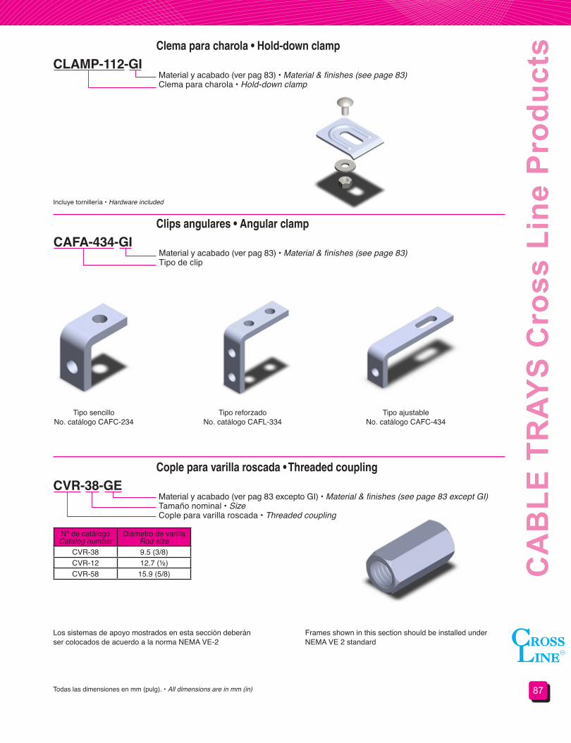
87
CA
BLE
TR
AYS
Cro
ss L
ine
Pro
duct
sClema para charola • Hold-down clamp
Clips angulares • Angular clamp
CLAMP-112-GI
CAFA-434-GI
Material y acabado (ver pag 83) • Material & finishes (see page 83)Clema para charola • Hold-down clamp
Material y acabado (ver pag 83) • Material & finishes (see page 83)Tipo de clip
Incluye tornillería • Hardware included
Tipo sencilloNo. catálogo CAFC-234
Tipo reforzadoNo. catálogo CAFL-334
Tipo ajustableNo. catálogo CAFC-434
Cople para varilla roscada • Threaded coupling
CVR-38-GEMaterial y acabado (ver pag 83 excepto GI) • Material & finishes (see page 83 except GI)Tamaño nominal • SizeCople para varilla roscada • Threaded coupling
N° de catálogoCatalog number
Diámetro de varilla Rod size
CVR-38 9.5 (3/8)CVR-12 12.7 (½)CVR-58 15.9 (5/8)
Los sistemas de apoyo mostrados en esta sección deberán ser colocados de acuerdo a la norma NEMA VE-2
Frames shown in this section should be installed under NEMA VE 2 standard
Todas las dimensiones en mm (pulg). • All dimensions are in mm (in)
CH
AR
OLA
S P
rodu
ctos
Cro
ss L
ine
88
¡¡¡EN CHAROLAS SEGUIMOS SIENDO SU MEJOR OPCIÓN!!! • IN CABLE TRAY SYSTEMS WE ARE, AGAIN, YOUR BEST CHOICE!!!
El sistema de soportería para cables tipo escalera fabricado en fibra de vidrio marca CROSS LINE es ideal en instalaciones donde se necesita una alta resistencia a la corrosión y donde no se requieran materiales conductores.
Este sistema está diseñado para las condiciones más severas, brindando además el sistema más resistente mecánicamente al tener travesaños atornillados a los perfiles laterales mediante varilla roscada.
Las características que hacen del sistema de fibra de vidrio CROSS LINE, un sistema superior son:
ALTA RESISTENCIA CONTRA RAYOS ULTRAVIOLETA E INTEMPERIE.- Los componentes de poliéster reforzados con fibra de vidrio cuentan con un velo protector aplicado en las superficies exteriores para resistir las inclemencias del tiempo y la acción de los rayos ultravioleta, además, dentro de la formulación, EXCLUSIVA DE CROSS LINE, se integran estabilizadores que aumentan la resistencia, así como pigmentos especiales que sirven como pantalla contra los rayos ultravioleta.
RETARDANTE DE FUEGO.- Por pruebas realizadas en laboratorio y en campo, se demuestra que las charolas evitan la propagación del fuego y auto extinguen cualquier flama en un lapso no mayor a 15 segundos, por otro lado los humos generados durante un evento no son tóxicos a bajas exposiciones.
RESISTENCIA A LA TEMPERATURA.- Las charolas de fibra de vidrio de CROSS LINE tienen un alto grado de resistencia a los cambios de temperatura y a temperaturas extremas, pudiendo ser usadas en cualquier ambiente.
GRAN RESISTENCIA MECÁNICA.- Por su diseño, materiales y método de fabricación estas charolas son más fuertes comparadas con los sistemas metálicos.
FACILIDAD DE INSTALACIÓN.- las charolas de fibra de vidrio son fácilmente perforadas o cortadas con herramientas metálicas, ya que no necesita ser rebabeado. Sus uniones atornillables permiten remover, reponer o trasladar secciones o partes de la instalación.
CROSS LINE’s fiber glass ladder type cable tray system is the best choice for electrical installations where high corrosion resistance and non conductive materials are required.
This system is designed for the most hazardous corrosive environments, being also the most mechanically resistant system as its rungs are bolted to the side rails using threaded rods.
In the following paragraphs we explain why the CROSS LINE fiber glass system is the best choice:
HIGH UV-RAY AND WEATHERING RESISTANCE.- Our fiber glass composite products have an external surface protection veil to protect them against weathering and UV rays.
FLAME RETARDANT.- In field and lab tests, CROSS LINE’s fiber glass products prevent flames spreading and it extinguishes in a no longer than 15 seconds period. Generated smoke is not toxic in low exposures.
TEMPERATURE RESISTANCE.- CROSS LINE’s fiber glass systems have high temperature’s changes resistance grade and can be used in any environment with a good profile.
HIGH MECHANICAL RESISTANCE.- By its design, materials and manufacturing process CROSS LINE’s fiber glass systems are stronger than metallic systems.
EASY INSTALLATION.- CROSS LINE’s fiber glass systems can be easily drilled or cut using metal working tools does not need to be deburred. It’s bolted unions facilitates jobsite removal, replacement and relocate installed parts.
The most important, CROSS LINE’s cable tray systems cover all you need for a complete installation. Straight sections, fittings, connections and covers, all are included in our product line, if you don´t find the accessory you need please consult our technical department..... We can make it.
Sección 4.5Soportería para cables tipo escalera de fibra
de vidrio
Section 4.5Fiber glass ladder type
cable tray systems.
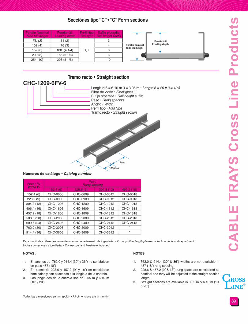
89
CA
BLE
TR
AYS
Cro
ss L
ine
Pro
duct
sSecciónes tipo “C” • “C” Form sections
Tramo recto • Straight section
Peralte NominalSide rail height
Peralte útilLoading depth
Perfil tipoRail type
Sufijo p/peralteRail height Suffix
76. (3) 51 (2)
C, E
3102 (4) 76 (3) 4152 (6) 108 (4 1/4) 6203 (8) 156 (6 1/8) 8
254 (10) 206 (8 1/8) 10
CHC-1209-6FV-6Longitud 6 = 6.10 m 3 = 3.05 m • Length 6 = 20 ft 3 = 10 ftFibra de vidrio • Fiber glassSufijo p/peralte • Rail height suffix Paso • Rung spacingAncho • WidthPerfil tipo • Rail typeTramo recto • Straight section
Ancho WWidth W
PasoRung spacing
152.4 (6) 228.6 (9) 304.8 (12) 457.2 (18)152.4 (6) CHC-0606 CHC-0609 CHC-0612 CHC-0618228.9 (9) CHC-0906 CHC-0909 CHC-0912 CHC-0918
304.8 (12) CHC-1206 CHC-1209 CHC-1212 CHC-1218406.4 (16) CHC-1606 CHC-1609 CHC-1612 CHC-1618457.2 (18) CHC-1806 CHC-1809 CHC-1812 CHC-1818508.0 (20) CHC-2006 CHC-2009 CHC-2012 CHC-2018609.6 (24) CHC-2406 CHC-2409 CHC-2412 CHC-2418762.0 (30) CHC-3006 CHC-3009 CHC-3012 *914.4 (36) CHC-3606 CHC-3609 CHC-3612 *
Números de catálogo • Catalog number
NOTAS :
1. En anchos de 762.0 y 914.4 (30” y 36”) no se fabrican en paso 457 (18”)
2. En pasos de 228.6 y 457.2 (9” y 18”) se consideran nominales y son ajustados a la longitud de la charola.
3. Las longitudes de la charola son de 3.05 m y 6.10 m (10’ y 20’)
NOTES :
1. 762.0 & 914.4 (30” & 36”) widths are not available in 457 (18”) rung spacing.
2. 228.6 & 457.2 (9” & 18”) rung space are considered as nominal and they will be adjusted to the straight section length.
3. Straight sections are available in 3.05 m & 6.10 m (10’ & 20’)
Para longitudes diferentes consulte nuestro departamento de ingeniería. • For any other length please contact our technical department.Incluye conectores y tornillería. • Connectors and hardware included
Todas las dimensiones en mm (pulg). • All dimensions are in mm (in)
W1/2 paso
Paso
Peralte nominalSiderailheight
Peralte útilLoadingdepth

CH
AR
OLA
S P
rodu
ctos
Cro
ss L
ine
90
Curva horizontal a 45° y 90° • 45° & 90° Horizontal bend
VHC-12R1290-4FVFibra de vidrio • Fiber glassSufijo p/peralte (ver pag 89) • Rail height suffix (see page 89)Ángulo de la curva • Angle bendRadio • RadiusAncho • WidthPerfil tipo • Rail typeCurva horizontal • Horizontal bend
Números de catálogo para curva a 90° • 90° Bend’s Catalog number
Números de catálogo para curva a 45° • 45° Bend’s Catalog number
Ancho WWidth W
RadioRadius
304.8 (12) 609.6 (24) 914.4 (36)152.4 (6) VHC-06R1290 VHC-06R2490 VHC-06R3690228.9 (9) VHC-09R1290 VHC-09R2490 VHC-09R3690
304.8 (12) VHC-12R1290 VHC-12R2490 VHC-12R3690406.4 (16) VHC-16R1290 VHC-16R2490 VHC-16R3690457.2 (18) VHC-18R1290 VHC-18R2490 VHC-18R3690508.0 (20) VHC-20R1290 VHC-20R2490 VHC-20R3690609.6 (24) VHC-24R1290 VHC-24R2490 VHC-24R3690762.0 (30) VHC-30R1290 VHC-30R2490 VHC-30R3690914.4 (36) VHC-36R1290 VHC-36R2490 VHC-36R3690
Ancho WWidth W
RadioRadius
304.8 (12) 609.6 (24) 914.4 (36)152.4 (6) VHC-06R1245 VHC-06R2445 VHC-06R3645228.9 (9) VHC-09R1245 VHC-09R2445 VHC-09R3645
304.8 (12) VHC-12R1245 VHC-12R2445 VHC-12R3645406.4 (16) VHC-16R1245 VHC-16R2445 VHC-16R3645457.2 (18) VHC-18R1245 VHC-18R2445 VHC-18R3645508.0 (20) VHC-20R1245 VHC-20R2445 VHC-20R3645609.6 (24) VHC-24R1245 VHC-24R2445 VHC-24R3645762.0 (30) VHC-30R1245 VHC-30R2445 VHC-30R3645914.4 (36) VHC-36R1245 VHC-36R2445 VHC-36R3645
Todas las dimensiones en mm (pulg) • All dimensions are in mm (in)Incluye conectores y tornillería • Connectors and hardware included
W
W
R
R90°
45°

91
CA
BLE
TR
AYS
Cro
ss L
ine
Pro
duct
sCurva vertical exterior a 45° y 90° • 45° & 90° Outside vertical bend
VEC-12R1290-4FVFibra de vidrio • Fiber glassSufijo p/peralte (ver pag 89) • Rail height suffix (see page 89)Ángulo de la curva • Angle bendRadio • RadiusAncho • WidthPerfil tipo • Rail typeCurva vertical exterior • Outside vertical bend
Números de catálogo para curva a 90° • 90° Bend’s Catalog number
Números de catálogo para curva a 45° • 45° Bend’s Catalog number
Ancho WWidth W
RadioRadius
304.8 (12) 609.6 (24) 914.4 (36)152.4 (6) VEC-06R1290 VEC-06R2490 VEC-06R3690228.9 (9) VEC-09R1290 VEC-09R2490 VEC-09R3690
304.8 (12) VEC-12R1290 VEC-12R2490 VEC-12R3690406.4 (16) VEC-16R1290 VEC-16R2490 VEC-16R3690457.2 (18) VEC-18R1290 VEC-18R2490 VEC-18R3690508.0 (20) VEC-20R1290 VEC-20R2490 VEC-20R3690609.6 (24) VEC-24R1290 VEC-24R2490 VEC-24R3690762.0 (30) VEC-30R1290 VEC-30R2490 VEC-30R3690914.4 (36) VEC-36R1290 VEC-36R2490 VEC-36R3690
Ancho WWidth W
RadioRadius
304.8 (12) 609.6 (24) 914.4 (36)152.4 (6) VEC-06R1245 VEC-06R2445 VEC-06R3645228.9 (9) VEC-09R1245 VEC-09R2445 VEC-09R3645
304.8 (12) VEC-12R1245 VEC-12R2445 VEC-12R3645406.4 (16) VEC-16R1245 VEC-16R2445 VEC-16R3645457.2 (18) VEC-18R1245 VEC-18R2445 VEC-18R3645508.0 (20) VEC-20R1245 VEC-20R2445 VEC-20R3645609.6 (24) VEC-24R1245 VEC-24R2445 VEC-24R3645762.0 (30) VEC-30R1245 VEC-30R2445 VEC-30R3645914.4 (36) VEC-36R1245 VEC-36R2445 VEC-36R3645
Todas las dimensiones en mm (pulg) • All dimensions are in mm (in)Incluye conectores y tornillería • Connectors and hardware included
W
W
RR
45°
90°

CH
AR
OLA
S P
rodu
ctos
Cro
ss L
ine
92
W
R90°
Curva vertical interior a 45° y 90° • 45° & 90° Inside vertical bend
VIC-12R1290-4FVFibra de vidrio • Fiber glassSufijo p/peralte (ver pag 89) • Rail height suffix (see page 89)Ángulo de la curva • Angle bendRadio • RadiusAncho • WidthPerfil tipo • Rail typeCurva vertical interior • Inside vertical bend
Números de catálogo para curva a 90° • 90° Bend’s Catalog number
Números de catálogo para curva a 45° • 45° Bend’s Catalog number
Ancho WWidth W
RadioRadius
304.8 (12) 609.6 (24) 914.4 (36)152.4 (6) VIC-06R1290 VIC-06R2490 VIC-06R3690228.9 (9) VIC-09R1290 VIC-09R2490 VIC-09R3690
304.8 (12) VIC-12R1290 VIC-12R2490 VIC-12R3690406.4 (16) VIC-16R1290 VIC-16R2490 VIC-16R3690457.2 (18) VIC-18R1290 VIC-18R2490 VIC-18R3690508.0 (20) VIC-20R1290 VIC-20R2490 VIC-20R3690609.6 (24) VIC-24R1290 VIC-24R2490 VIC-24R3690762.0 (30) VIC-30R1290 VIC-30R2490 VIC-30R3690914.4 (36) VIC-36R1290 VIC-36R2490 VIC-36R3690
Ancho WWidth W
RadioRadius
304.8 (12) 609.6 (24) 914.4 (36)152.4 (6) VIC-06R1245 VIC-06R2445 VIC-06R3645228.9 (9) VIC-09R1245 VIC-09R2445 VIC-09R3645
304.8 (12) VIC-12R1245 VIC-12R2445 VIC-12R3645406.4 (16) VIC-16R1245 VIC-16R2445 VIC-16R3645457.2 (18) VIC-18R1245 VIC-18R2445 VIC-18R3645508.0 (20) VIC-20R1245 VIC-20R2445 VIC-20R3645609.6 (24) VIC-24R1245 VIC-24R2445 VIC-24R3645762.0 (30) VIC-30R1245 VIC-30R2445 VIC-30R3645914.4 (36) VIC-36R1245 VIC-36R2445 VIC-36R3645
Todas las dimensiones en mm (pulg) • All dimensions are in mm (in)Incluye conectores y tornillería • Connectors and hardware included
W
R
45°

93
CA
BLE
TR
AYS
Cro
ss L
ine
Pro
duct
s“T” Horizontal • Horizontal tee
“X” Horizontal • Horizontal cross
THC-12R12-4FV
XHC-12R12-4FV
Fibra de vidrio • Fiber glassSufijo p/peralte (ver pag 89) • Rail height suffix (see page 89)Radio • RadiusAncho • WidthPerfil tipo • Rail type“T” horizontal • Horizontal Tee
Fibra de vidrio • Fiber glassSufijo p/peralte (ver pag 89) • Rail height suffix (see page 89)Radio • RadiusAncho • WidthPerfil tipo • Rail type“X” horizontal • Horizontal cross
Números de catálogo • Catalog number
Números de catálogo • Catalog number
Ancho WWidth W
RadioRadius
304.8 (12) 609.6 (24) 914.4 (36)152.4 (6) THC-06R12 THC-06R24 THC-06R36228.9 (9) THC-09R12 THC-09R24 THC-09R36
304.8 (12) THC-12R12 THC-12R24 THC-12R36406.4 (16) THC-16R12 THC-16R24 THC-16R36457.2 (18) THC-18R12 THC-18R24 THC-18R36508.0 (20) THC-20R12 THC-20R24 THC-20R36609.6 (24) THC-24R12 THC-24R24 THC-24R36762.0 (30) THC-30R12 THC-30R24 THC-30R36914.4 (36) THC-36R12 THC-36R24 THC-36R36
Ancho WWidth W
RadioRadius
304.8 (12) 609.6 (24) 914.4 (36)152.4 (6) XHC-06R12 XHC-06R24 XHC-06R36228.9 (9) XHC-09R12 XHC-09R24 XHC-09R36
304.8 (12) XHC-12R12 XHC-12R24 XHC-12R36406.4 (16) XHC-16R12 XHC-16R24 XHC-16R36457.2 (18) XHC-18R12 XHC-18R24 XHC-18R36508.0 (20) XHC-20R12 XHC-20R24 XHC-20R36609.6 (24) XHC-24R12 XHC-24R24 XHC-24R36762.0 (30) XHC-30R12 XHC-30R24 XHC-30R36914.4 (36) XHC-36R12 XHC-36R24 XHC-36R36
R
R
W
W
90°
90°
Incluye conectores y tornillería • Connectors and hardware included
Incluye conectores y tornillería • Connectors and hardware included
Todas las dimensiones en mm (pulg) • All dimensions are in mm (in)

CH
AR
OLA
S P
rodu
ctos
Cro
ss L
ine
94
RectaStraight
DerechaRight
IzquierdaLeft
RLC-1209-4FV Reducciones • Reducers
Fibra de vidrio • Fiber glassSufijo p/peralte (ver pag 89) • Rail height suffix (see page 89)Ancho menor • Smaller widthAncho mayor • Larger widthPerfil tipo (ver pag 89) • Rail type (see page 89)Reducción • ReducerRL = Recta • StraightRLD = Derecha • RightRLI = Izquierda • Left
Todas las dimensiones en mm (pulg) • All dimensions are in mm (in)Incluye conectores y tornillería • Connectors and hardware included
N° de catálogo reducciones rectas • Straight reducer catalog number
N° de catálogo reducciones derechas • Right reducer catalog number
N° de catálogo reducciones izquierdas • Left reducer catalog number
Ancho W1Width W1
Ancho menor W2Smaller width W2
152.4 (6) 228.9 (9) 304.8 (12) 406.4 (16) 457.2 (18) 508.0 (20) 609.6 (24) 762.0 (30)152.4 (6)228.9 (9) RLC-0906
304.8 (12) RLC-1206 RLC-1209406.4 (16) RLC-1606 RLC-1609 RLC-1612457.2 (18) RLC-1806 RLC-1809 RLC-1812 RLC-1816508.0 (20) RLC-2006 RLC-2009 RLC-2012 RLC-2016 RLC-2018609.6 (24) RLC-2406 RLC-2409 RLC-2412 RLC-2416 RLC-2418 RLC-2420762.0 (30) RLC-3006 RLC-3009 RLC-3012 RLC-3016 RLC-3018 RLC-3020 RLC-3024914.4 (36) RLC-3606 RLC-3609 RLC-3612 RLC-3616 RLC-3618 RLC-3620 RLC-3624 RLC-3630
Ancho W1Width W1
Ancho menor W2Smaller width W2
152.4 (6) 228.9 (9) 304.8 (12) 406.4 (16) 457.2 (18) 508.0 (20) 609.6 (24) 762.0 (30)152.4 (6)228.9 (9) RLDC-0906
304.8 (12) RLDC-1206 RLDC-1209406.4 (16) RLDC-1606 RLDC-1609 RLDC-1612457.2 (18) RLDC-1806 RLDC-1809 RLDC-1812 RLDC-1816508.0 (20) RLDC-2006 RLDC-2009 RLDC-2012 RLDC-2016 RLDC-2018609.6 (24) RLDC-2406 RLDC-2409 RLDC-2412 RLDC-2416 RLDC-2418 RLDC-2420762.0 (30) RLDC-3006 RLDC-3009 RLDC-3012 RLDC-3016 RLDC-3018 RLDC-3020 RLDC-3024914.4 (36) RLDC-3606 RLDC-3609 RLDC-3612 RLDC-3616 RLDC-3618 RLDC-3620 RLDC-3624 RLDC-3630
Ancho W1Width W1
Ancho menor W2Smaller width W2
152.4 (6) 228.9 (9) 304.8 (12) 406.4 (16) 457.2 (18) 508.0 (20) 609.6 (24) 762.0 (30)152.4 (6)228.9 (9) RLIC-0906
304.8 (12) RLIC-1206 RLIC-1209406.4 (16) RLIC-1606 RLIC-1609 RLIC-1612457.2 (18) RLIC-1806 RLIC-1809 RLIC-1812 RLIC-1816508.0 (20) RLIC-2006 RLIC-2009 RLIC-2012 RLIC-2016 RLIC-2018609.6 (24) RLIC-2406 RLIC-2409 RLIC-2412 RLIC-2416 RLIC-2418 RLIC-2420762.0 (30) RLIC-3006 RLIC-3009 RLIC-3012 RLIC-3016 RLIC-3018 RLIC-3020 RLIC-3024914.4 (36) RLIC-3606 RLIC-3609 RLIC-3612 RLIC-3616 RLIC-3618 RLIC-3620 RLIC-3624 RLIC-3630
W1
W1 W2
W2W2 W1

95
CA
BLE
TR
AYS
Cro
ss L
ine
Pro
duct
s“T” Vertical • Vertical tee
Curva vertical ajustable • Vertical adjustable bend
TVC-12R12-4FV
VAC-12R12-4FV
Fibra de vidrio • Fiber glassSufijo p/peralte (ver pag 89) • Rail height suffix (see page 89)Radio • RadiusAncho • WidthPerfil tipo • Rail type“T” vertical • Vertical Tee
Fibra de vidrio • Fiber glassSufijo p/peralte (ver pag 89) • Rail height suffix (see page 89)Radio • RadiusAncho • WidthPerfil tipo • Rail typeCurva vertical ajustable • Vertical adjustable bend
Ancho WWidth W
RadioRadius
304.8 (12) 609.6 (24) 914.4 (36)152.4 (6) TVC-06R12 TVC-06R24 TVC-06R36228.9 (9) TVC-09R12 TVC-09R24 TVC-09R36
304.8 (12) TVC-12R12 TVC-12R24 TVC-12R36406.4 (16) TVC-16R12 TVC-16R24 TVC-16R36457.2 (18) TVC-18R12 TVC-18R24 TVC-18R36508.0 (20) TVC-20R12 TVC-20R24 TVC-20R36609.6 (24) TVC-24R12 TVC-24R24 TVC-24R36762.0 (30) TVC-30R12 TVC-30R24 TVC-30R36914.4 (36) TVC-36R12 TVC-36R24 TVC-36R36
Ancho WWidth W
RadioRadius
304.8 (12) 609.6 (24) 914.4 (36)152.4 (6) VAC-06R12 VAC-06R24 VAC-06R36228.9 (9) VAC-09R12 VAC-09R24 VAC-09R36
304.8 (12) VAC-12R12 VAC-12R24 VAC-12R36406.4 (16) VAC-16R12 VAC-16R24 VAC-16R36457.2 (18) VAC-18R12 VAC-18R24 VAC-18R36508.0 (20) VAC-20R12 VAC-20R24 VAC-20R36609.6 (24) VAC-24R12 VAC-24R24 VAC-24R36762.0 (30) VAC-30R12 VAC-30R24 VAC-30R36914.4 (36) VAC-36R12 VAC-36R24 VAC-36R36
Todas las dimensiones en mm (pulg) • All dimensions are in mm (in)
Incluye conectores y tornillería • Connectors and hardware included
Incluye conectores y tornillería • Connectors and hardware included
90°W
R
N° de catálogo • Catalog number
N° de catálogo • Catalog number
W
R

CH
AR
OLA
S P
rodu
ctos
Cro
ss L
ine
96
Incluye tornillería de acero inoxidable encapsulados en fibra de vidrio • Stainless steel encased in fiber glass bolts included.
Incluye tornillería de acero inoxidable encapsulados en fibra de vidrio • Stainless steel encased in fiber glass bolts included.
AR Tipo rectoSplice plate AR TYPE
AH Tipo horizontal ajustableHorizontal adjustable AH TYPE
EA Tipo vertical ajustableVertical adjustable EA TYPE
AE Conector de expansiónExpansion connector AE TYPE
Conectores • Connectors
Conectores verticales de ángulo fijo • Fixed angle vertical connectors
Conectores horizontales de ángulo fijo • Fixed angle horizontal connectors
AE-4FV
AV30-4FV
AHF30-4FV
Fibra de vidrio • Fiber glassSufijo p/peralte (ver pag 89) • Rail height suffix (see page 89)Conector tipo • Connector type
Fibra de vidrio • Fiber glassSufijo p/peralte (ver pag 89) • Rail height suffix (see page 89)Conector tipo • Connector type
Fibra de vidrio • Fiber glassSufijo p/peralte (ver pag 89) • Rail height suffix (see page 89)Conector tipo • Connector type
ÁnguloAngle
Conector tipoConnector type
22.5° AV2230° AV3045° AV4560° AV6090° AV90
ÁnguloAngle
Conector tipoConnector type
22.5° AHF2230° AHF3045° AHF4560° AHF6090° AHF90
ÁnguloAngle
ÁnguloAngle
Incluye tornillería de acero inoxidable encapsulados en fibra de vidrio • Stainless steel encased in fiber glass bolts included.SUGERENCIA DE USO: El conector AHF90 puede ser usado en pares como CONECTOR A CAJA.

97
CA
BLE
TR
AYS
Cro
ss L
ine
Pro
duct
s
Todas las dimensiones en mm (pulg) • All dimensions are in mm (in)
Incluye tornillería de acero inoxidable encapsulados en fibra de vidrio • Stainless steel encased in fiber glass bolts included.
Placa terminal • Blind end
Conectores horizontales de ángulo fijo • Fixed angle horizontal connectors
PTR-12-4FV Fibra de vidrio • Fiber glassSufijo p/peralte (ver pag 89) • Rail height suffix (see page 89)Ancho de la charola • Tray widthTapa terminal • Blind end
Tapa recta sin ventilación • Non vented flat cover
Tapa recta con ventilación • Vented flat cover
TR THC-12R12-4FV
TRV THC-12R12-4FV
Fibra de vidrio • Fiber glassSufijo p/peralte (ver pag 89) • Rail height suffix (see page 89)No de catálogo de el producto a recubrir • Covered product catalog numberTapa recta no ventilada • Non vented flat cover
Fibra de vidrio • Fiber glassSufijo p/peralte (ver pag 89) • Rail height suffix (see page 89)No de catálogo de el producto a recubrir • Covered product catalog numberTapa recta ventilada • Vented flat cover
La longitud de la tapa para tramo recto es de 3.048 m.
Cada tapa para tramo recto incluye 6 clips de sujeción de acero inoxidable.
El número de clips para tapas de accesorios estará en función del accesorio.
For straight section, the cover length is 3.048 m (10 ft) and 6 cover clamps are included.
For fittings the cover clamps quantity is according to the fitting.
La longitud de la tapa para tramo recto es de 3.048 m.
Cada tapa para tramo recto incluye 4 pares de juegos de separadores.
El número de clips para tapas de accesorios estará en función del accesorio.
For straight section, the cover length is 3.048 m (10 ft) and 4 pairs cover clamps kits are included.
For fittings the cover clamp quantity is according to the fitting.
The anchorage holes should be field made.

CH
AR
OLA
S P
rodu
ctos
Cro
ss L
ine
98
Las barreras separadoras para tramos rectos se surten en Longitudes de 3.048 metros y deberán ser instaladas en campo.
Cada barrera separadora incluye 3 juegos de clips (placa, y tornillería).
Debido a que es imposible determinar con anticipación la posición de la barrera en un accesorio, cuando se requiera se deberá solicitar barreras para tramos rectos y deberán ser cortadas e instaladas en campo.
For straight section, the barrier length is 3.048 m (10 ft) and 3 barrier clamp kits (platter and hardware) are included.
The barriers should be field installed.
Barreras separadoras • Barrier strips
BSCH-4FV Fibra de vidrio • Fiber glassSufijo p/peralte (ver pag 89) • Rail height suffix (see page 89)Barrera separadora • Barrier strip
Tapa a dos aguas con ventilación • Vented peaked cover
TA CHC-1209-4FV Fibra de vidrio • Fiber glassSufijo p/peralte (ver pag 89) • Rail height suffix (see page 89)No de catálogo de el producto a recubrir • Covered product catalog numberTapa a dos aguas ventilada • Vented peaked cover
La longitud de la tapa es de 3.048 m.
Este tipo de tapa no está disponible para accesorios.
The cover length is 3.048 m (10 ft) and 4 pairs of kits cover clamps are included.
This cover type in not available for fitting.
The anchorage holes should be field made.
Todas las dimensiones en mm (pulg) • All dimensions are in mm (in)

99
CA
BLE
TR
AYS
Cro
ss L
ine
Pro
duct
s
Incluye 3 clips de fijación • Includes 3 fixation clips
Incluye clips de fijación • Fixation clips included
Barrera separadora para accesiorios horizontales • Horizontal accessories barrier strip
Barrera separadora para accesorios verticales • Vertical accessories barrier strip
BSH-48 4FV
BSVEC-R1290 4FV
Fibra de vidrio • Fiber glassSufijo p/peralte (ver pag 89) • Rail height suffix (see page 89)Largo en pulgadas (48” y 72”) • Length in inches (48” & 72”)Barrera separadora accesorios horizontales • Horizontal accessories barrier strip
No requiere tornillería de fijación • Hardware not needed.
Bajada para cables • Drop out
BC-24R05AI P/FVMaterial y acabado • Material & finishesRadio de la bajada • Drop out radiusAncho de la charola • Tray widthBajada para cable • Drop out
Fibra de vidrio • Fiber glassSufijo p/peralte (ver pag 89) • Rail height suffix (see page 89)Ángulo de la curva • Bend angleRadio • RadiusTipo de curva • Bend typeBarrera separadora • Barrier strip

CH
AR
OLA
S P
rodu
ctos
Cro
ss L
ine
100
Longitud 3.05m • Length: 3.05m.Todas las dimensiones en mm (pulg) • All dimensions are in mm (in)
Unicanal de fibra de vidrio. • Fiber glass unistrut
LU-1000FVFibra de vidrio • Fiber glassTipo unicanal (1000 y 3300) • Channel type (1000 & 3300)Tramo recto unicanal • Straight channel
No. catálogoCatalog number
AnchoWidth
AlturaHeight
LU-100044.45 (1.750”)
44.45 (1.750”)LU-3300 25.05 (0.986”)
Un conector tipo AR y tornillería incluidos • AR connector type and hardware includedTodas las dimensiones en mm (pulg) • All dimensions are in mm (in)
Para curvas y derivaciones utilizar los conectores mostrados en la pag 96 donde el ancho del canal equivale al peralte de la charola tipo escalera.For fittings use the connectors showed in page 96 where the channel tray width is the same as the rail height in ladder tray.
Canaleta • Channel tray
CHSV-4305-FV Fibra de vidrio • Fiber glassLongitud 305 = 3.048m (10 ft), 610 = 6.096m (20 ft)Length 305 = 3.048m (10 ft), 610 = 6.096m (20 ft) Ancho • WidthTipo SV= liso CV = perforado • Type SV= solid CV= slottedCanaleta • Channel tray
Ancho WWidth W
Altura PHigh P
Tipo lisoSolid type
Tipo perforado Slotted type
3.048 (10 ft) 6.096 (20 ft) 3.048 (10 ft) 6.096 (20 ft)76 (3) 25 (1) CHSV-3305FV CHSV-3610FV CHCV-3305FV CHCV-3610FV
102 (4) 32 (1 1/4) CHSV-4305FV CHSV-4610FV CHCV-4305FV CHCV-4610FV152 (6) 32 (1 1/4) CHSV-6305FV CHSV-6610FV CHCV-6305FV CHCV-6610FV203 (8) 32 (1 1/4) CHSV-8305FV CHSV-8610FV CHCV-8305FV CHCV-8610FV
254 (10) 51 (2) CHSV-10305FV CHSV-10610FV CHCV-10305FV CHCV-10610FV
Clema en acero inoxidable, incluye tornillería • Clamp made of stainless steel, hardware included.
Clema para charola • Hold-down clamp
CLAMP-112AI P/FV
Clemas en fibra de vidrio. Incluyen tornillería en acero inoxidable encapsulada en fibra de vidrio.Clamps made of fiber glass. Stainless steel fiber glass encased hardware included.
Esta clema es fabricada en acero inoxidable The clamp is made of stainless steel
CLAMP-112FV CLAMPGUIA-112FV

101
CA
BLE
TR
AYS
Cro
ss L
ine
Pro
duct
sMénsula para montaje en pared • Wall cantilever bracket
MPP-06 FVMaterial y acabado • Material & finishesAncho de charola • Cable tray widthMénsula para pared • Wall supported bracket
Ancho de charolaTray width A No de catálogo
Catalog number L
101.6 (4)152.4 (6)228.9 (9)
304.8 (12)
254 (10)
MPP-04MPP-06MPP-09MPP-12
165.1 (6.5)215.9 (8.5)292.1 (11.5)368.3 (14.5)
406.4 (16)457.2 (18)508.0 (20)609.6 (24)762.0 (30)914.4 (36)
304.8 (12)
MPP-16MPP-18MPP-20MPP-24MPP-30MPP-36
469.9 (18.5)520.7 (20.5)571.5 (22.5)673.1 (26.5)825.5 (32.5)977.9 (38.5)
No incluye clemas ni sistemas de fijación. • Hardware, clamps or anchoring system are not included.
Canal horizontal para trapecio • Horizontal channel for support
CPV-06FVMaterial y acabado • Material & finishesAncho de charola • Cable tray widthCanal horizontal para trapecio • Horizontal channel for support
Canal horizontal profundoDeep horizontal channel
Ancho de charolaTray width L
CPV-04CPV-06CPV-09CPV-12CPV-16CPV-18CPV-20CPV-24CPV-30CPV-36
101.6 (4)152.4 (6)228.9 (9)
304.8 (12)406.4 (16)457.2 (18)508.0 (20)609.6 (24)762.0 (30)914.4 (36)
216 (8.50)267 (10.50)343 (13.50)419 (16.50)521 (20.50)572 (22.50)622 (24.50) 724 (28.50)876 (34.50)
1029 (40.50)No incluye tornillería, varillas, clips “U” ni sistemas de fijación • Hardware, threaded rods or anchoring systems are not included.
L
A
L
50.8 (2)
Clip “U”
Varilla roscada
Fibra de vidrio • Fiber glassLongitud 305 = 3.048m (10 ft), 610 = 6.096m (20 ft)Length 305 = 3.048m (10 ft), 610 = 6.096m (20 ft) Ancho • WidthTipo SV= liso CV = perforado • Type SV= solid CV= slottedCanaleta • Channel tray
N° de catálogo • Catalog number

CH
AR
OLA
S P
rodu
ctos
Cro
ss L
ine
102
Ancho WWidth W
PeralteSide rail height
35 60 85 110100 CHM-100-35 CHM-100-60 CHM-100-85 CHM-100-110200 CHM-200-35 CHM-200-60 CHM-200-85 CHM-200-110300 CHM-300-35 CHM-300-60 CHM-300-85 CHM-300-110400 CHM-400-60 CHM-400-85 CHM-400-110500 CHM-500-60 CHM-500-85 CHM-500-110600 CHM-600-60 CHM-600-85 CHM-600-110
Sección 4.6Soportería para cables
tipo marino
Section 4.6Marine type cable tray
system.
Tramo recto • Straight section
CHM-100-35GIMaterial y acabado • Material & finishesSufijo p/peralte • Rail height suffixAncho • WidthTipo marino • Marine typeTramo recto • Straight section
Materiales y acabados:A: Aluminio aleación AA-3003 acabado naturalGI: Lámina galvanizadaAI: Acero inoxidable
Para materiales y acabados no indicados consulte nuestro departamento de ingeniería.Todas las dimensiones en mm (pulg)
Materials&finishes:A: AA-3003 natural finished aluminumGI: Galvanized sheetAI: Stainless steel
For materials and finishes not shown please consult our technical department.All dimensions are in mm (in)
N° de catálogo • Catalog number
Peralte nominalSiderailheight
W
Longitud estándar 3.0 m.Para longitudes diferentes consulte nuestro departamento de técnico.
Incluye conector(es) y tornillería.
Standard length 3.000 mFor any other length please contact our technical department
Connector(s) and hardware included

103
CA
BLE
TR
AYS
Cro
ss L
ine
Pro
duct
sCurva horizontal a 45° y 90° • 45° & 90° Horizontal bend
“T” Horizontal • Horizontal “TEE”
VHM-100R25090-35GI
THM-100R250-35GI
Material y acabado (ver pag 102) • Material & finish (see page 102)Sufijo p/peralte (ver pag 102) • Rail height suffix (see page 102)Ángulo de la curva • Angle bendRadio (disponible en 250) • Radius (available in 10”)Ancho • WidthTipo marino • Marine typeCurva horizontal • Horizontal bend
Material y acabado (ver pag 102) • Material & finish (see page 102)Sufijo p/peralte (ver pag 102) • Rail height suffix (see page 102)Radio (disponible en 250) • Radius (available in 10”)Ancho • WidthTipo marino • Marine type“T” horizontal • Horizontal “Tee”
Todas las dimensiones en mm (pulg) • All dimensions are in mm (in)
Incluye conector(es) y tornillería • Connector(s) and hardware included
Incluye conector(es) y tornillería • Connector(s) and hardware included
Ancho WWidth W
ÁnguloAngle
45º 90º100 VHM-100R25045 VHM-100R25045200 VHM-200R25045 VHM-200R25045300 VHM-300R25045 VHM-300R25045400 VHM-400R25045 VHM-400R25045500 VHM-500R25045 VHM-500R25045600 VHM-600R25045 VHM-600R25045
No. de catálogoCatalog number
Ancho WWidth W
THM-100R250 100 THM-200R250 200 THM-300R250 300THM-400R250 400THM-500R250 500THM-600R250 600
W WR 250
R 250
90° 45°
90°
W R 250

CH
AR
OLA
S P
rodu
ctos
Cro
ss L
ine
104
“EQUIS” Horizontal • Horizontal cross
Reducciones • Reducer
XHM-100R250-35GI
RLM-300200-35GI
Material y acabado (ver pag 102) • Material & finish (see page 102)Sufijo p/peralte (ver pag 102) • Rail height suffix (see page 102)Radio (disponible en 250) • Radius (available in 10”)Ancho • WidthTipo marino • Marine typeEquis horizontal • Horizontal cross
Material y acabado (ver pag 102) • Material & finish (see page 102)Sufijo p/peralte (ver pag 102) • Rail height suffix (see page 102)Ancho menor • Smallest widthAncho mayor • Largest widthTipo marino • Marine typeReducción • Reducer
Todas las dimensiones en mm (pulg) • All dimensions are in mm (in)Incluye conector(es) y tornillería • Connector(s) and hardware included
Incluye conector(es) y tornillería • Connector(s) and hardware includedTodas las dimensiones en mm (pulg) • All dimensions are in mm (in)
Ancho W1Width W1
Ancho menor W2 Smallest width W2
100 200 300 400 500200 RLM-200100300 RLM-300100 RLM-300200400 RLM-400100 RLM-400200 RLM-400300500 RLM-500100 RLM-500200 RLM-500300 RLM-500400600 RLM-600100 RLM-600200 RLM-600300 RLM-600400 RLM-600500
No. de catálogoCatalog number
Ancho WWidth W
XHM-100R250 100 XHM-200R250 200 XHM-300R250 300XHM-400R250 400XHM-500R250 500XHM-600R250 600
W R 250
W1
W2
N° de catálogo reducciones rectas • Straight reducer catalog number
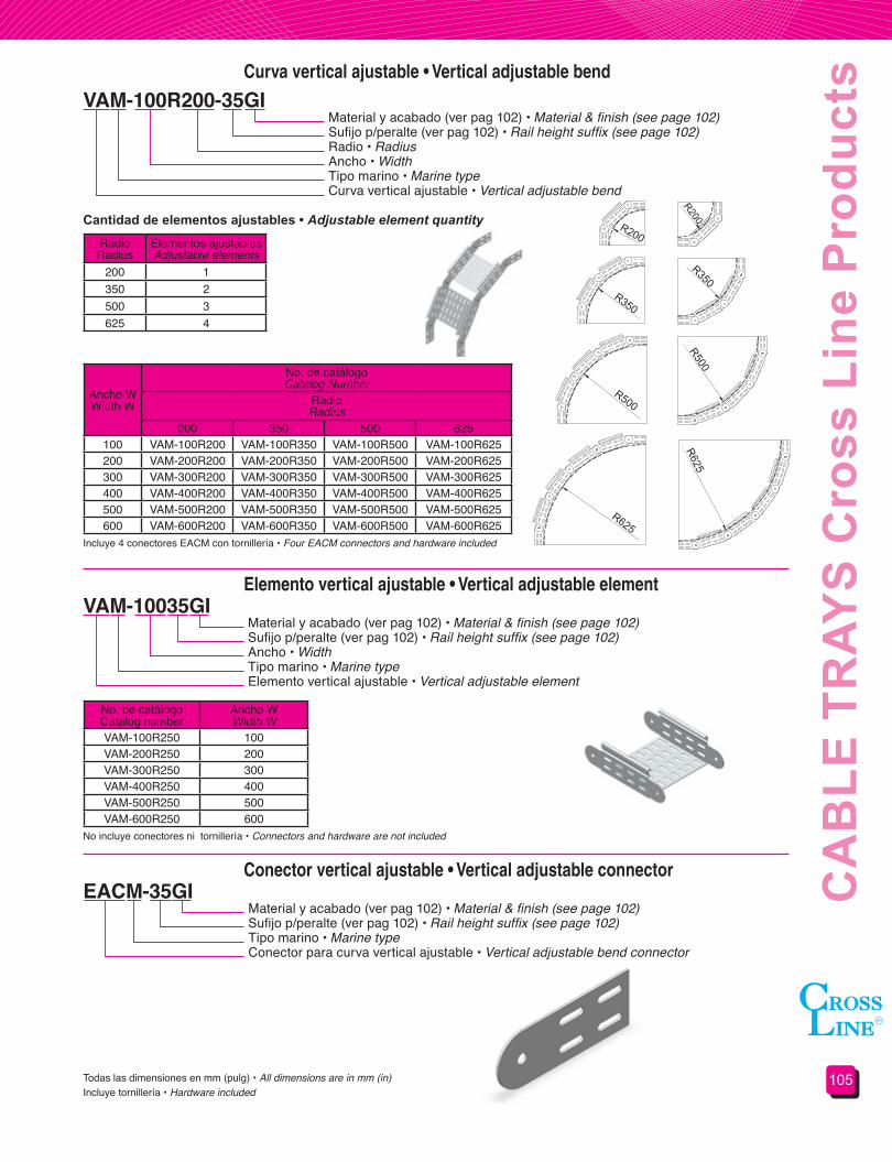
105
CA
BLE
TR
AYS
Cro
ss L
ine
Pro
duct
sCurva vertical ajustable • Vertical adjustable bend
VAM-100R200-35GIMaterial y acabado (ver pag 102) • Material & finish (see page 102)Sufijo p/peralte (ver pag 102) • Rail height suffix (see page 102)Radio • RadiusAncho • WidthTipo marino • Marine typeCurva vertical ajustable • Vertical adjustable bend
RadioRadius
Elementos ajustablesAdjustable elements
200 1350 2500 3625 4
Cantidad de elementos ajustables • Adjustable element quantity
Ancho WWidth W
No. de catálogoCatalog Number
RadioRadius
200 350 500 625100 VAM-100R200 VAM-100R350 VAM-100R500 VAM-100R625200 VAM-200R200 VAM-200R350 VAM-200R500 VAM-200R625300 VAM-300R200 VAM-300R350 VAM-300R500 VAM-300R625400 VAM-400R200 VAM-400R350 VAM-400R500 VAM-400R625500 VAM-500R200 VAM-500R350 VAM-500R500 VAM-500R625600 VAM-600R200 VAM-600R350 VAM-600R500 VAM-600R625
Incluye 4 conectores EACM con tornillería • Four EACM connectors and hardware included
No incluye conectores ni tornillería • Connectors and hardware are not included
Todas las dimensiones en mm (pulg) • All dimensions are in mm (in) Incluye tornillería • Hardware included
No. de catálogoCatalog number
Ancho WWidth W
VAM-100R250 100 VAM-200R250 200 VAM-300R250 300VAM-400R250 400VAM-500R250 500VAM-600R250 600
Elemento vertical ajustable • Vertical adjustable element
Conector vertical ajustable • Vertical adjustable connector
VAM-10035GI
EACM-35GI
Material y acabado (ver pag 102) • Material & finish (see page 102)Sufijo p/peralte (ver pag 102) • Rail height suffix (see page 102)Ancho • WidthTipo marino • Marine typeElemento vertical ajustable • Vertical adjustable element
Material y acabado (ver pag 102) • Material & finish (see page 102)Sufijo p/peralte (ver pag 102) • Rail height suffix (see page 102)Tipo marino • Marine typeConector para curva vertical ajustable • Vertical adjustable bend connector
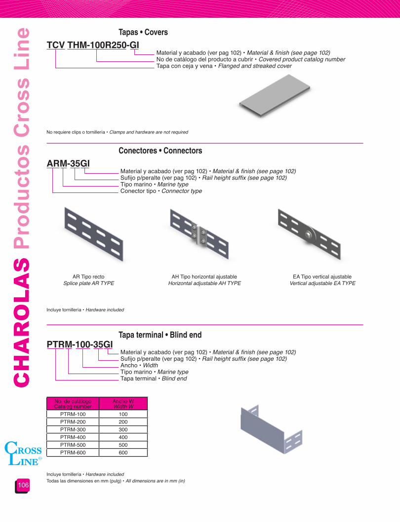
CH
AR
OLA
S P
rodu
ctos
Cro
ss L
ine
106
No requiere clips o tornillería • Clamps and hardware are not required
Incluye tornillería • Hardware included
Incluye tornillería • Hardware included
Tapa terminal • Blind end
Conectores • Connectors
PTRM-100-35GI
ARM-35GI
Material y acabado (ver pag 102) • Material & finish (see page 102)Sufijo p/peralte (ver pag 102) • Rail height suffix (see page 102)Ancho • WidthTipo marino • Marine typeTapa terminal • Blind end
Material y acabado (ver pag 102) • Material & finish (see page 102)Sufijo p/peralte (ver pag 102) • Rail height suffix (see page 102)Tipo marino • Marine typeConector tipo • Connector type
Todas las dimensiones en mm (pulg) • All dimensions are in mm (in)
Tapas • Covers
TCV THM-100R250-GIMaterial y acabado (ver pag 102) • Material & finish (see page 102)No de catálogo del producto a cubrir • Covered product catalog numberTapa con ceja y vena • Flanged and streaked cover
AR Tipo rectoSplice plate AR TYPE
AH Tipo horizontal ajustableHorizontal adjustable AH TYPE
EA Tipo vertical ajustableVertical adjustable EA TYPE
No. de catálogoCatalog number
Ancho WWidth W
PTRM-100 100 PTRM-200 200 PTRM-300 300PTRM-400 400PTRM-500 500PTRM-600 600

107
CA
BLE
TR
AYS
Cro
ss L
ine
Pro
duct
s
¡¡¡EN CHAROLAS SEGUIMOS SIENDO SU MEJOR OPCION!!! • IN CABLE TRAY SYSTEMS WE ARE, AGAIN, YOUR BEST CHOICE!!!
Los sistemas de soportería para cables tipo malla fabricados por CROSS LINE son desarrollos pensados para instalaciones de control, señalización e iluminación, donde se requieren cargas bajas, como son: tiendas de autoservicio, cuartos de máquinas, cuartos de control, edificios inteligentes, cableados estructurados y toda aplicación donde no se presenten riesgos de daños a cables.
Los sistemas de soportería para cables tipo malla de CROSS LINE están fabricados de filamentos de acero longitudinales, de alta resistencia a la tensión, estos filamentos son unidos entre sí mediante filamentos transversales que le dan cohesión y rigidez al sistema.
El diseño exclusivo de CROSS LINE cuenta en la parte superior con filamentos continuos brindando flexibilidad ante cargas excesivas evitando el colapso del sistema.
Debido a la característica anterior existen señales visuales de que el sistema está sobrecargado y puede corregirse la carga, aun sin presentarse la falla del sistema.
Al evitarse el colapso, el sistema es más seguro que los sistemas rígidos.
El diseño del filamento superior evita la caída de los cables durante la instalación haciéndola más rápida y eficaz.
La posición del filamento superior evita el daño al aislamiento de los cables.
El diseño de la varilla continua, así como la geometría del mismo permiten que este funcione como rodillo haciendo más fácil el jalado de los cables durante la instalación.
Al ser ventilados los cables, permiten una mayor capacidad de conducción.
Permiten la acometida de cables tanto por la parte superior como inferior y lateral.
Son de fácil instalación y las modificaciones, así como derivaciones y curvas pueden realizarse en campo con herramientas mínimas.
El sistema es muchísimo más ligero que los sistemas rígidos ahorrando en anclaje, estructuración y sistemas de apoyo.
Por esta y muchas razones más:
CROSS LINE’s wire mesh type cable tray system was designed thinking in control, signal and lighting electrical installation where light loads are required. Ideal for stores, control rooms, machines rooms, intelligent buildings, structural cabling and all applications where cables aren’t in risk of damage.
CROSS LINE’s wire mesh type cable tray system are made of high strength resistance steel, longitudinal filaments are joined for transversal wires providing cohesion and rigidity to the system.
CROSS LINE’s wire mesh cable trays design have a filament in the top of the tray which gives high flexibility when the system is excessively loaded, preventing system’s failure.
This filament makes possible to see when the system is overloaded. So this system is safer than rigid systems because it can´t be overloaded. It also prevents insulation damage during installation.
This system makes installation and maintenance an easy and fast task.
The filament’s position and form makes a roll bar function, enabling an easy installation while pulling cables
As this system is vented, it provides a wider conduction capacity. Moreover it makes possible to drop out cables from all positions, top, bottom and sides.
Installation and assembly needs are really easy to fulfill as fittings are field made with a minimum of tools.
This system is lighter than rigid systems offering to you a cheaper structural and support system.
Sección 4.7Soportería para cables
tipo malla
Section 4.7Wire mesh type cable
tray system

CH
AR
OLA
S P
rodu
ctos
Cro
ss L
ine
108
Los accesorios se fabrican a partir de tramos rectos en campo, por tanto no se ofrecen en este catálogo.
Conectores y tornillería no se incluyen, estos deberán ser solicitados por separado de acuerdo a los accesorios que serán fabricados en campo.
Fittings not showed should be field made using straight sections.
Neither connectors nor hardware are included, they should be requested according to the fitting you will make in field.
Tramo recto • Straight section
Mini-CL • Mini-CL
CL-10030GIMaterial y acabado • Material & finishSufijo p/peralte • Rail height suffixAncho • WidthTramo recto • Straight section
Ancho WWidth W
PeralteHeight
30 55 10550 CL-5030 CL-5055
100 CL-10030 CL-10055150 CL-15030 CL-15055200 CL-20030 CL-20055 CL-200105300 CL-30030 CL-30055 CL-300105450 CL-45055 CL-450105600 CL-600105
N° de catálogo • Catalog number
Longitud estandard 3.000 m • Standard length 3.000 m
Se puede solicitar con borde de seguridad engargolado. • It can be ordered with seamed safety edge.
W
W
Peralte nominalSiderailheight
49
49
24
Materiales y acabados:GI: Acero al carbón Galvanizado por Inmersión en caliente GE: Acero al carbón Galvanizado ElectrolíticoT: Acero al carbón TropicalizadoPVC: Acero al carbón Recubierto con PVC según NEMA RN 1AI: Acero inoxidableP: Pintura electrostática (Ver gama de colores)Para materiales y acabados no indicados consulte nuestro departamento de ingeniería Todas las dimensiones en mm (pulg)
Materials&finishes:GI: Hot dip galvanized steelGE: Electro galvanized steelT: Chromium-zinc coated steelPVC: PVC coated steel under NEMA RN 1AI: Stainless steelP: Electrostatic paint (See color pattern)For materials and finishes not shown please consult our technical departmentAll dimensions are in mm (in)
Charolaconbordeengargolado

109
CA
BLE
TR
AYS
Cro
ss L
ine
Pro
duct
sConectores universales • Standard connectors
Conector reforzado • Reinforced connector
Conector angular • Angle connector
CUCL-01
AEDT
AT 90
No. de catálogoCatalog number
Pieza 1Ditto 1
Pieza 2Ditto 2
CUCL-01 CE-25 CE-30
Cada conector incluye • Each connector includes
Los conectores pueden ser solicitados por juego (CUCL) o por partes (CE)Ambos conectores incluyen tornillería cuando son solicitados en juegoAl final del número de catálogo indicar material y acabado (ver página 108)
Connectors can be requested in kit (CUCL) or in parts (CE)Hardware included when they are requested in kitAt the end of the catalog number add material and finish (see page 108)
CUCL-01
No incluye conectores ni tornillería • Hardware and connectors are not included
No incluye conectores ni tornillería • Hardware and connectors are not included
Al final del número de catálogo indicar material y acabado (ver página 108) • At the end of the catalog number add material and finish (see page 108)
Al final del número de catálogo indicar material y acabado (ver página 108) • At the end of the catalog number add material and finish (see page 108)

CH
AR
OLA
S P
rodu
ctos
Cro
ss L
ine
110
Conectores rectos • Long splice plate
Conectores angular corto • Small angular connector
Clip colgante • Hanger clamp
AD 275AD 75
AD 250/90
AS
No incluye conectores ni tornillería • Hardware and connectors are not included
No incluye conectores ni tornillería • Hardware and connectors are not included
No incluye varilla • Rod not included
Al final del número de catálogo indicar material y acabado (ver página 108) • At the end of the catalog number add material and finish (see page 108)
Al final del número de catálogo indicar material y acabado (ver página 108) • At the end of the catalog number add material and finish (see page 108)
Al final del número de catálogo indicar material y acabado (ver página 108) • At the end of the catalog number add material and finish (see page 108)Todas las dimensiones en mm (pulg) • All dimensions are in mm (in)

111
CA
BLE
TR
AYS
Cro
ss L
ine
Pro
duct
s
Ancho charolaTray width
No. de catálogoCatalog number
50 SCCL-50100 SCCL-100150 SCCL-150200 SCCL-200300 SCCL-300450 SCCL-450600 SCCL-600
Ancho charolaTray width
No. de catálogoCatalog number
50 CRP-50100 CRP-100150 CRP-150200 CRP-200300 CRP-300450 CRP-450600 CRP-600
Ancho charolaTray width
No. de catálogoCatalog number
50 CS-50100 CS-100150 CS-150200 CS-200300 CS-300450 CS-450600 CS-600
Todas las dimensiones en mm (pulg) • All dimensions are in mm (in)No incluye tornillería, varillas, clips “U” ni sistemas de fijación • Hardware, “U” clamp, threaded rods or anchoring systems are not included.
Soporte colgante • Hanger support
Ménsula para pared • Wall cantilever bracket
Canal horizontal para trapecio • Horizontal channel for trapeze support
SCCL-100GI
CRP-100GI
CS-100GI
Material y acabado (ver pag 108) • Material & finish (see page 108)Ancho • WidthColgador • Hanger
Material y acabado (ver pag 108) • Material & finish (see page 108)Ancho • WidthMénsula para charola de malla • Wire mesh tray bracket
Material y acabado (ver pag 108) • Material & finish (see page 108)Ancho • WidthCanal horizontal charola de malla • Wire mesh tray horizontal channel
Clip “U”“U” Form clampVarilla roscada
Threadedrod

CH
AR
OLA
S P
rodu
ctos
Cro
ss L
ine
112
Longitud del canalChannel length
No. de catálogoCatalog number
150 UCSN-150200 UCSN-200300 UCSN-300400 UCSN-400500 UCSN-500600 UCSN-600
1000 UCSN-10002000 UCSN-20003000 UCSN-3000
No. de catálogoCatalog number
Longitud LLength L
MSNC-100 178MSNC-150 228MSNC-200 278MSNC-300 378MSNC-450 528MSNC-600 678
Todas las dimensiones en mm (pulg) • All dimensions are in mm (in)
No incluye tornillería, varillas, clips “U” ni sistemas de fijación • Hardware, “u” clamp, threaded rods or anchoring systems are not included
Canal universal • Universal channel
Ménsula de ensamble rápido • Fast assembly bracket
Soporte para piso • Floor support
UCSN-500GI
SPCL
MSNC
Material y acabado (ver pag 108) • Material & finish (see page 108)Longitud • LengthCanal universal • Universal channel
L
63
100
Clip “U”“U” Form clamp
Varilla roscadaThreadedrod
Al final del número de catálogo indicar material y acabado (ver página 108) • At the end of the catalog number add material and finish (see page 108)
Al final del número de catálogo indicar material y acabado (ver página 108) • At the end of the catalog number add material and finish (see page 108)

113
CA
BLE
TR
AYS
Cro
ss L
ine
Pro
duct
s
No. de catálogoCatalog number
Ancho charolaTray width
TCCL-50 50 TCCL-100 100 TCCL-150 150 TCCL-200 200 TCCL-300 300 TCCL-450 450 TCCL-600 600
Todas las dimensiones en mm (pulg) • All dimensions are in mm (in)
Soporte a muro o caja • Wall or box support
Tapas • Covers
Bajada para cable • Drop out
CM-55CM-55XL
TCCL-100GI
BCL-10R50
Material y acabado (ver pag 108) • Material & finish (see page 108)Ancho • WidthTapa con ceja para charola tipo malla • Flanged cover for wire mesh tray
Al final del número de catálogo indicar material y acabado (ver página 108) • At the end of the catalog number add material and finish (see page 108)
Al final del número de catálogo indicar material y acabado (ver página 108) • At the end of the catalog number add material and finish (see page 108)
Debido a que en charola tipo malla las derivaciones se realizan a partir de tramos rectos, las tapas para derivaciones deberán obtenerse a partir de tapas rectas.
Fitting covers should be field made using straight section covers.
3000(9.84’)
Para retirar introducir desarmadorFor disassembly use a screwdriver
Para sujetar doblar estas 4 pestañas
For assembly bend the four lift
25 (1)
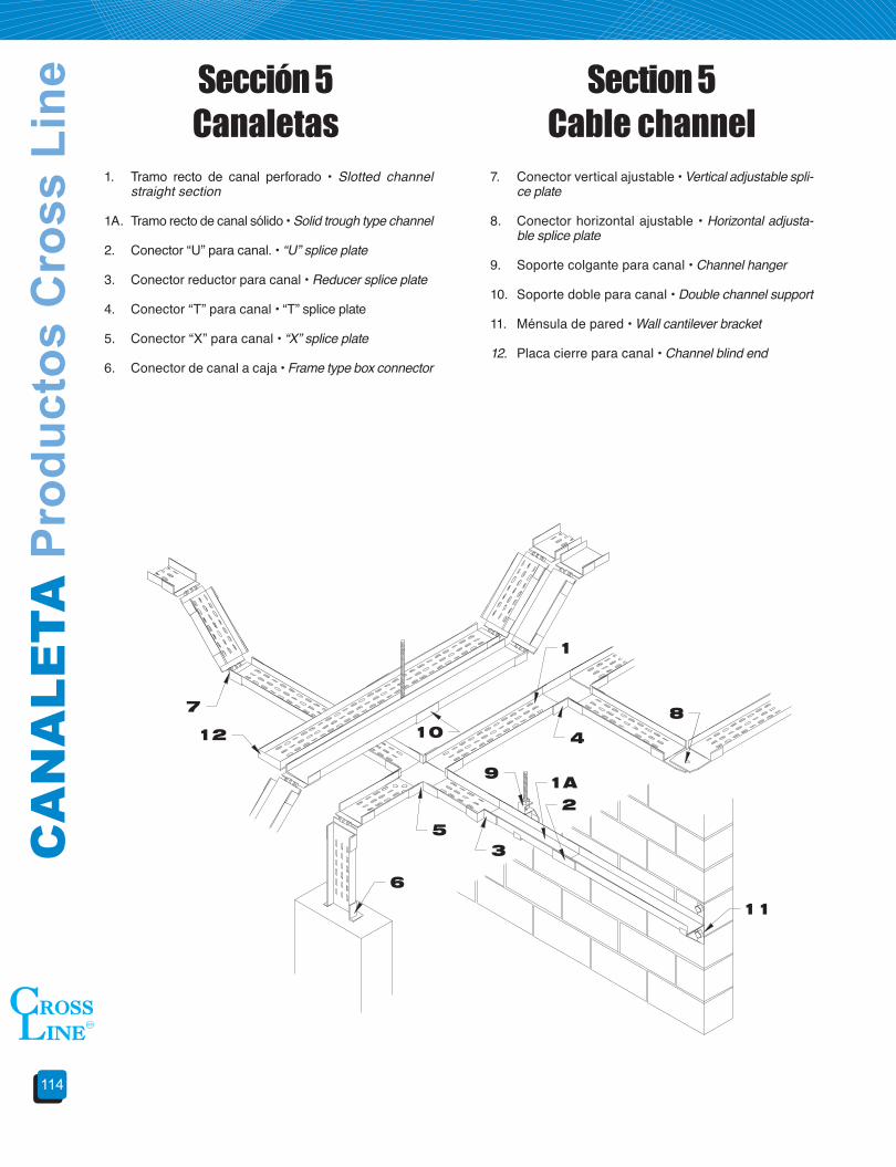
CA
NA
LETA
Pro
duct
os C
ross
Lin
e
114
1. Tramo recto de canal perforado • Slotted channel straight section
1A. Tramo recto de canal sólido • Solid trough type channel
2. Conector “U” para canal. • “U” splice plate
3. Conector reductor para canal • Reducer splice plate
4. Conector “T” para canal • “T” splice plate
5. Conector “X” para canal • “X” splice plate
6. Conector de canal a caja • Frame type box connector
7. Conector vertical ajustable • Vertical adjustable spli-ce plate
8. Conector horizontal ajustable • Horizontal adjusta-ble splice plate
9. Soporte colgante para canal • Channel hanger
10. Soporte doble para canal • Double channel support
11. Ménsula de pared • Wall cantilever bracket
12. Placa cierre para canal • Channel blind end
Sección 5 Canaletas
Section 5 Cable channel

115
CA
BLE
CH
AN
NE
L C
ross
Lin
e Pr
oduc
tsTramo recto • Straight section
Conector “U” • “U” Splice plate
CHSV-4152 32A
AUCV-3 A
Material y acabado • Material & finishPeralte en mm • Depth in mmLongitud en cm • Length in cmAncho en pulgadas • Width in inchesTipo de fondo • Trough typeTramo recto • Straight section
Material y acabado • Material & finishAncho en pulgadas • Width in inchesPara canaleta • For cable channelConector “U” • “U” splice plate
Ancho WWidth W
Fondo perforadoSlotted Trough
Fondo lisoSolid Trough
Longitud • Length Longitud • Length1524 (60) 3048 (120) 1524 (60) 3048 (120)
76 (3) CHCV-3152 CHCV-3305 CHSV-3152 CHSV-3305102 (4) CHCV-4152 CHCV-4305 CHSV-4152 CHSV-4305152 (6) CHCV-6152 CHCV-6305 CHSV-6152 CHSV-6305
N° de catálogo • Catalog number
Incluye conector y tornillería • Connector and hardware included
Incluye tornillería • Hardware included
Materiales y acabados:A: Aluminio aleación AA-3003 acabado naturalGI: Acero al carbón galvanizado por inmersión en calienteGE: Acero al carbón galvanizado electrolíticoT: Acero al carbón tropicalizadoPVC: Acero al carbón recubierto con PVC según NEMA RN 1PVA: Aluminio recubierto con PVC según NEMA RN 1 AI: Acero inoxidablePara materiales y acabados no indicados consulte nuestro departamento de ingeniería.Todas las dimensiones en mm (pulg).
Materials&finishes:A: AA-3003 natural finished aluminumGI: Hot dip galvanized steelGE: Electro galvanized steelT: Chromium-zinc coated steelPVC: PVC coated steel under NEMA RN 1PVA: PVC coated aluminum under NEMA RN 1AI: Stainless steelFor materials and finishes not shown please consult our technical department.All dimensions are in mm (in).
Ancho WWidth W
PeralteDepth
76 (3) 32 mm ( 1 1/4”)
102 (4)32 mm ( 1 1/4”)44 mm ( 1 3/4”)
152 (6) 44 mm ( 1 3/4”)
No. de catálogoCatalog number
Ancho WWidth W
AUCV-3 76 (3)AUCV-4 102 (4)AUCV-6 152 (6)
W
W

CA
NA
LETA
Pro
duct
os C
ross
Lin
e
116
Conector “T” • “T” Splice plate
Conector “X” • “X” Splice plate
Conector reductor • Reducer splice plate
ATCV-3 A
AXCV-3 A
ARCV-63 A
Material y acabado (ver pág. 115) • Material & finish (see page 115)Ancho en pulgadas • Width in inchesPara canaleta • For cable channelConector “T” • “T” splice plate
Material y acabado (ver pág. 115) • Material & finish (see page 115)Ancho en pulgadas • Width in inchesPara canaleta • For cable channelConector “X” • “X” splice plate
Material y acabado (ver pág. 115) • Material & finish (see page 115)Ancho menor en pulg. • Smallest width in inchesAncho mayor en pulg. • Largest width in inchesPara canaleta • For cable channelConector reductor • Reducer splice plate
Incluye tornillería • Hardware included
Incluye tornillería • Hardware included
Incluye tornillería • Hardware includedTodas las dimensiones en mm (pulg) • All dimensions are in mm (in)
No. de catálogoCatalog number
Ancho WWidth W
ATCV-3 76 (3)ATCV-4 102 (4)ATCV-6 152 (6)
No. de catálogoCatalog number
Ancho WWidth W
AXCV-3 76 (3)AXCV-4 102 (4)AXCV-6 152 (6)
Ancho W1Width W1
Ancho W2Width W2
76 (3) 102 (4)102 (4) ARCV-43152 (6) ARCV-63 ARCV-64
N° de catálogo • Catalog number
Conector vertical ajustable • Vertical adjustable splice plate
AVACV-3 AMaterial y acabado (ver pág. 115) • Material & finish (see page 115)Ancho en pulgadas • Width in inchesPara canaleta • For cable channel Conector vertical ajustable • Vertical adjustable splice plate
Incluye tornillería • Hardware included
No. de catálogoCatalog number
Ancho WWidth W
AVACV-3 76 (3)AVACV-4 102 (4)AVACV-6 152 (6)
W1
W2

117
CA
BLE
CH
AN
NE
L C
ross
Lin
e Pr
oduc
ts
Placa terminal • Blind end
Conector horizontal ajustable • Horizontal adjustable splice plate
Tapas • Covers
Conector a caja • Frame box connector
PTRCV-3 A
AHACV-3 A
TCHCV-3152 A
ACCV-6 A
Material y acabado (ver pág. 115) • Material & finish (see page 115)Ancho en pulgadas • Width in inchesPara canaleta • For cable channel Placa terminal • Blind end
Material y acabado (ver pág. 115) • Material & finish (see page 115)Ancho en pulgadas • Width in inchesPara canaleta • For cable channelConector horizontal ajustable • Horizontal adjustable splice plate
Material y acabado (ver pág. 115) • Material & finish (see page 115)Longitud en cm • Length in cmAncho en pulgadas • Width in inchesTipo de fondo • Trough typeTapa para tramo recto • Cover for straight section
Material y acabado (ver pág. 115) • Material & finish (see page 115)Ancho de canaleta • Channel widthConector a caja para canaleta• Channel frame box connector
Incluye tornillería • Hardware included
Incluye tornillería • Hardware included
Incluye tornillería • Hardware includedTodas las dimensiones en mm (pulg) • All dimensions are in mm (in)
Todas las dimensiones en mm (pulg) • All dimensions are in mm (in)
No. de catálogoCatalog number
Ancho WWidth W
PTRCV-3 76 (3)PTRCV-4 102 (4)PTRCV-6 152 (6)
No. de catálogoCatalog number
Ancho WWidth W
AHACV-3 76 (3)AHACV-4 102 (4)AHACV-6 152 (6)
Ancho WWidth W
LongitudLength
1524 (60) 3048 (120)76 (3) TCHCV-3152 TCHCV-3305
102 (4) TCHCV-4152 TCHCV-4305152 (6) TCHCV-6152 TCHCV-6305
Ancho W1Width W1
Ancho W2Width W2
ACCV-3 76 (3)ACCV-4 102 (4)ACCV-6 152 (6)
N° de catálogo • Catalog number
N° de catálogo • Catalog number

CA
NA
LETA
Pro
duct
os C
ross
Lin
e
118
Ménsula para pared • Wall cantilever bracket
Soporte doble • Double hanger support
Soporte colgante • Hanger support
Clip de sujeción para tapa • Cover clamp
MPCV-3GI
SDCV-3GI
SCCV-3GI
CSTCV-14GI
Material y acabado (ver pág. 115 excepto aluminio) • Material & finish (see page 115 except aluminum)Ancho en pulgadas • Width in inchesPara canaleta • For cable channel Ménsula para pared • Wall cantilever bracket
Material y acabado (ver pág. 115 excepto aluminio) • Material & finish (see page 115 except aluminum)Ancho en pulgadas • Width in inchesPara canaleta • For cable channel Soporte doble • Double support
Material y acabado (ver pág. 113 excepto aluminio) • Material & finish (see page 113 except aluminum)Ancho en pulgadas • Width in inchesPara canaleta • For cable channel Soporte colgante • Hanger support
Material y acabado (ver pág. 115) • Material & finish (see page 115)Clip de sujeción para tapa • Cover clamp
Incluye tornillería • Hardware included
Todas las dimensiones en mm (pulg) • All dimensions are in mm (in)
No. de catálogoCatalog number
Ancho WWidth W
MPCV-3 76 (3)MPCV-4 102 (4)MPCV-6 152 (6)
No. de catálogoCatalog number
Ancho WWidth W
SDCV-3 76 (3)SDCV-4 102 (4)SDCV-6 152 (6)
No. de catálogoCatalog number
Ancho WWidth W
SCCV-3 76 (3)SCCV-4 102 (4)SCCV-6 152 (6)
W
W