second publication of proposed means of compliance with
TRANSCRIPT
Second Publication of
Proposed Means of Compliance with the Special Condition VTOL
Doc. No: MOC-2 SC-VTOL Issue: 1 Date: 23 June 2021
PUBLIC CONSULTATION Page 1 of 94
Second Publication of Proposed Means of Compliance with the Special Condition
VTOL
The document at hand, Doc. No. MOC-2 SC-VTOL, contains the second publication of MOCs with the Special
Condition VTOL. It proposes new MOCs, as well as supplements and amendments to the ones already
published with Doc. No. MOC SC-VTOL, Issue 2. Following completion of this public consultation process, it is
planned to collect all final MOCs in an upcoming issue 3 of Doc. No. MOC SC-VTOL, for general convenience.
Statement of Issue
EASA has received a number of requests for the type certification of vertical take-off and landing (VTOL) aircraft,
which differ from conventional rotorcraft or fixed-wing aircraft. In the absence of suitable certification
specifications for the type certification of this type of product, a complete set of dedicated technical
specifications in the form of a Special Condition for VTOL aircraft was developed. The Special Condition
addresses the unique characteristics of these products and prescribes airworthiness standards for the issuance
of a type certificate, and changes to this type certificate, for a person-carrying VTOL aircraft in the small category,
with lift/thrust units that are used to generate powered lift and control.
This Special Condition was subject to a public consultation process and finally issued by EASA in July 2019.
The Special Condition VTOL establishes the safety and design objectives. This approach, previously utilised for
the development of CS-23 Amendment 5, is also used for VTOL designs in order not to limit technical innovation
by describing prescriptive design solutions as certification standards. The Special Condition does not contain the
means that are possible to demonstrate compliance with the safety and design objectives.
The Means Of Compliance (MOC) contained within this document address the applicant´s requests for
clarification of EASA’s interpretation of these objectives and of possibilities how to demonstrate compliance
with them. Some of these MOCs contain material which should be considered to be guidance material to assist
the applicant with an understanding of the objective rather than providing a definitive means of compliance.
In the preparation of these MOCs EASA has followed the same principles, and pursued the same objectives, as
with the Special Condition. First, to provide sufficient flexibility to address different architectures and design
concepts, although it is acknowledged that all possible cases cannot be considered in these MOCs and
alternatives can be proposed by applicants to address some particular design features. In addition, the proposed
MOCs should enable an equal treatment of all applicants, by establishing a level playing field and ensuring that
a comparable level of safety in the compliance with the objectives of the Special Condition is achieved by all
designs.
EASA is committed to continue supporting the industry in the development of safe VTOL aircraft. To this end
EASA has decided to prioritise the publication of MOC with the Special Condition VTOL and to issue them in a
sequential manner. This approach will allow EASA to focus its resources where the greatest safety impact will
be achieved and where the need for clarity is more urgently required. It will furthermore allow the industry to
gain an early insight into EASA’s interpretation and expectations from the design objectives of the Special
Second Publication of
Proposed Means of Compliance with the Special Condition VTOL
Doc. No: MOC-2 SC-VTOL Issue: 1 Date: 23 June 2021
PUBLIC CONSULTATION Page 2 of 94
Condition which could have an important effect in the design decisions, instead of waiting until exhaustive
guidance for the Special Condition is developed.
In May 2021, EASA completed the first publication of MOCs with the Special Condition VTOL in Doc. No. MOC
SC-VTOL, Issue 2. This document considered all comments received during the public consultation of Issue 1,
which were furthermore individually responded in an associated Comment Response Document, also published.
The document at hand, Doc. No. MOC-2 SC-VTOL, contains the second publication of MOCs with the Special
Condition VTOL. It proposes new MOCs, as well as supplements and amendments to the ones already published
with Doc. No. MOC SC-VTOL, Issue 2. Following completion of this public consultation process, it is planned to
collect all final MOCs in an upcoming issue 3 of Doc. No. MOC SC-VTOL, for general convenience.
Finally, it is recognised that the experience gained during the certification of these new products and their entry
into service will allow to increase the knowledge in their certification. It is possible that a better insight into the
particular characteristics of these products is gained, which might result in modifications of particular elements
of the first MOCs that are issued. EASA will do so considering first and foremost the safety of the European
citizens but also mindful of the effects on all stakeholders.
Log of issues
Issue Issue date Change description
1 23/06/2020 First Issue for Public Consultation
Second Publication of
Proposed Means of Compliance with the Special Condition VTOL
Doc. No: MOC-2 SC-VTOL Issue: 1 Date: 23 June 2021
PUBLIC CONSULTATION Page 3 of 94
Second Publication of Proposed Means of Compliance with the Special Condition
VTOL
Contents Statement of Issue ................................................................................................................................................... 1
Log of issues ............................................................................................................................................................. 2
MOC – SUBPART B – FLIGHT ................................................................................................................................... 5
MOC VTOL.2105 Performance Data ................................................................................................................... 5
MOC VTOL.2115 Take-off performance ............................................................................................................. 5
MOC VTOL.2120 Climb requirements .............................................................................................................. 16
MOC VTOL.2130 Landing .................................................................................................................................. 16
MOC – SUBPART C – STRUCTURES ....................................................................................................................... 18
MOC VTOL.2205 Interaction of systems and structures ................................................................................. 18
MOC VTOL.2210 Structural Design Loads ........................................................................................................ 23
MOC VTOL.2225 Component Loading Conditions ........................................................................................... 25
MOC VTOL.2240 (a) and (b) Structural durability ............................................................................................ 27
MOC VTOL.2240(d) High Energy Fragments – Particular Risk Analysis .......................................................... 38
MOC VTOL.2240 (e) In-Service Monitoring ...................................................................................................... 38
MOC VTOL.2245 Aeroelasticity ........................................................................................................................ 39
MOC VTOL.2250(c) No catastrophic effect from structural single failures in the Category Enhanced ......... 40
MOC VTOL.2250(e) Doors, canopies and exits ................................................................................................ 41
MOC VTOL.2255 Protection of structure ......................................................................................................... 42
MOC VTOL.2260 Materials and processes ....................................................................................................... 42
MOC VTOL.2265 Special factors of safety ........................................................................................................ 43
MOC VTOL.2270(c) Emergency Landing Conditions ........................................................................................ 43
MOC – SUBPART D – DESIGN AND CONSTRUCTION ............................................................................................ 46
MOC VTOL.2305 Landing Gear Systems ........................................................................................................... 46
MOC VTOL.2310(b) Emergency Flotation ........................................................................................................ 48
MOC VTOL.2310(c) Ditching ............................................................................................................................. 49
MOC VTOL.2315(a) Means of egress and emergency exits ............................................................................. 50
MOC VTOL.2320(a)(1) Clear communication between flight crew and passengers ...................................... 53
MOC VTOL.2320(a)(3) Occupant protection from breakage of windshields, windows, and canopies ......... 53
MOC VTOL.2325(b)(1) and (b)(2) Fire Protection: Minimisation of Fire Propagation .................................... 53
Second Publication of
Proposed Means of Compliance with the Special Condition VTOL
Doc. No: MOC-2 SC-VTOL Issue: 1 Date: 23 June 2021
PUBLIC CONSULTATION Page 4 of 94
MOC VTOL.2330 Fire Protection in designated fire zones .............................................................................. 54
MOC - SUBPART E – LIFT/THRUST SYSTEM INSTALLATION ................................................................................. 59
MOC VTOL.2400(c)(3) Lift/thrust system installation – likely hazards in operation ...................................... 59
MOC VTOL.2425(b) Shutdown and Restart of a Lift/Thrust Unit in Flight ...................................................... 64
MOC VTOL.2430(a)(3) and (a)(4) Accessible energy in electrical energy storage systems ............................ 65
MOC VTOL.2435(f) Prevention of likely foreign object damage to the lift/thrust unit ................................. 65
MOC VTOL.2435(g) Flight crew awareness of the lift/thrust unit configuration ........................................... 65
MOC – SUBPART F – SYSTEMS AND EQUIPMENT ................................................................................................ 67
MOC 4 VTOL.2500(b) Certification credit for simulation and rig tests ........................................................... 67
MOC VTOL.2510(a) Aircraft Parachute Rescue System ................................................................................... 72
MOC VTOL.2530 External and Cockpit Lighting ............................................................................................... 76
MOC VTOL.2535 Safety Equipment .................................................................................................................. 77
MOC – SUBPART G – FLIGHT CREW INTERFACE AND OTHER INFORMATION .................................................... 78
MOC VTOL.2600 Flight crew compartment ..................................................................................................... 78
MOC VTOL.2605 Installation and operation information ............................................................................... 84
MOC VTOL.2610 Instrument markings, control markings and placards ......................................................... 85
MOC VTOL.2620 Electronic Aircraft Flight Manual .......................................................................................... 86
MOC VTOL.2625 Instructions for Continued Airworthiness ............................................................................ 92
Second Publication of
Proposed Means of Compliance with the Special Condition VTOL
Doc. No: MOC-2 SC-VTOL Issue: 1 Date: 23 June 2021
PUBLIC CONSULTATION Page 5 of 94
MOC – SUBPART B – FLIGHT
MOC VTOL.2105 Performance Data
Wind conditions
(a) The most critical wind condition should be identified considering performance and controllability:
From take-off until reaching VTOSS (see MOC VTOL.2115) and from below VREF (see MOC
VTOL.2130) to landing (i.e. the ground referenced phase), at least 17 kts of relative steady
wind should be considered. Limitations (which are operationally feasible) in terms of wind
intensity and azimuth can however be proposed (e.g. no tailwinds on take-off) when
showing compliance to the requirements of Subpart B.
After reaching VTOSS and until VREF is achieved prior to landing (i.e. in an air referenced
phase), the effect of the relative wind (and gusts) should be considered on handling
qualities, using the MHQRM, and on performance.
(b) The performance data should be determined with the most critical wind condition identified in (a), in
nominal conditions and at the Certified Minimum Performance (CMP) following a Critical Failure for
Performance (CFP), which should in any case include:
a take-off and climb, and
an approach and landing, and
a maximum performance climb at VTOSS
Note: The definitions of CMP and CFP are included in MOC VTOL.2000. For reference, the CMP corresponds to
a critical engine failure (OEI) scenario of a Category A helicopter.
Cooling/heating losses
(a) The effect of cooling/heating losses should be considered when determining the performance of the
aircraft.
(b) The cooling/heating systems should be set in a position that will maintain the temperature of the
lift/thrust system components within the established limits.
Take-off, climb and landing speeds
The take-off, climb and landing speeds:
(a) are defined by their main characteristics in MOC VTOL.2115, 2120 and 2130.
(b) should represent the minimum conditions for the definition of a safe take-off and landing path.
(c) should guarantee minimum performance and controllability in different combinations of power setting
and aircraft configuration.
MOC VTOL.2115 Take-off performance
Introduction to take-off paths:
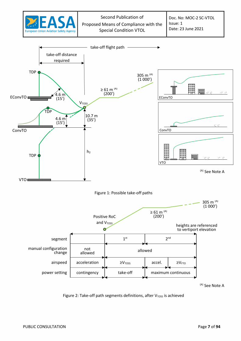
(a) Helicopter Category A foresees two possible take-off paths, one for Conventional Take-Off (ConvTO) and
another for Elevated ConvTO (EConvTO) (Figure 1). The EConvTO differs from the ConvTO operation in
that a dropdown below the surface level is allowed provided obstacle clearances (15ft of edge clearance)
Second Publication of
Proposed Means of Compliance with the Special Condition VTOL
Doc. No: MOC-2 SC-VTOL Issue: 1 Date: 23 June 2021
PUBLIC CONSULTATION Page 6 of 94
are maintained until reaching the take-off safety speed VTOSS (defined below). These two take-off paths
are applicable to the VTOL aircraft with some adaptations for the VTOL flight mechanics.
(b) A third take-off path, Vertical Take-Off (VTO) (Figure 1), is also proposed with the objective of providing
an adapted take-off path for VTOL urban environment operations from vertiports (see “Vertical take-off
and landing procedure” in section 13):
Obstacle clearance is established from the height of a “virtual elevated vertiport”, which is
set at the top of the vertical climb.
The protection surfaces are established at the height of the virtual elevated vertiport, since
the minimum gradients should be determined and demonstrated after reaching VTOSS.
During the vertical segment, it should be possible to perform a Rejected Take-Off (RTO)
before reaching the Take-off Decision Point (TDP). Visual or synthetic cues can be used.
After the TDP it should be possible to perform a Continued Take-off (CTO). The applicant
may choose to have a pure vertical or a backup (rearward) take-off trajectory. The maximum
deviations from the nominal trajectories should be determined.
The TDP in the vertical segment can be placed at any point. Some applicants might elect to
have a TDP lower than the top of the vertical segment, if the RTO cannot be performed
safely from a given height upwards while meeting the Certified Minimum Performance
(CMP) following a Critical Failure for Performance (CFP). Others may set the TDP at the
bottom of the vertical segment because the RTO is not a foreseen option.
(c) The differences between the three profiles lie only at the initial portion of the take-off trajectory and
acceleration to forward flight, until VTOSS and a positive rate of climb (RoC) are achieved. The trajectories
on Figure 1 are depicted considering that a CFP occurs soon after the TDP. A common minimum take-
off path definition after VTOSS is possible (Figure 2).
Second Publication of
Proposed Means of Compliance with the Special Condition VTOL
Doc. No: MOC-2 SC-VTOL Issue: 1 Date: 23 June 2021
PUBLIC CONSULTATION Page 7 of 94
Figure 1: Possible take-off paths
Figure 2: Take-off path segments definitions, after VTOSS is achieved
take-off flight path
take-off distance
required
EConvTO
TDP
4.6 m (15’)
ConvTO
TDP
VTOSS
4.6 m (15’)
10.7 m (35’)
h2
VTO
TDP
305 m (A) (1 000’)
ConvTO
EConvTO
VTO
≥ 61 m (A) (200’)
305 m (A) (1 000’)
Positive RoC
and VTOSS
≥ 61 m (A) (200’)
heights are referenced to vertiport elevation
manual configuration change
segment
power setting
airspeed
not allowed
acceleration
contingency
1st
≥VTOSS
take-off
accel.
maximum continuous
2nd
≥VFTO
allowed
(A) See Note A
(A) See Note A
Second Publication of
Proposed Means of Compliance with the Special Condition VTOL
Doc. No: MOC-2 SC-VTOL Issue: 1 Date: 23 June 2021
PUBLIC CONSULTATION Page 8 of 94
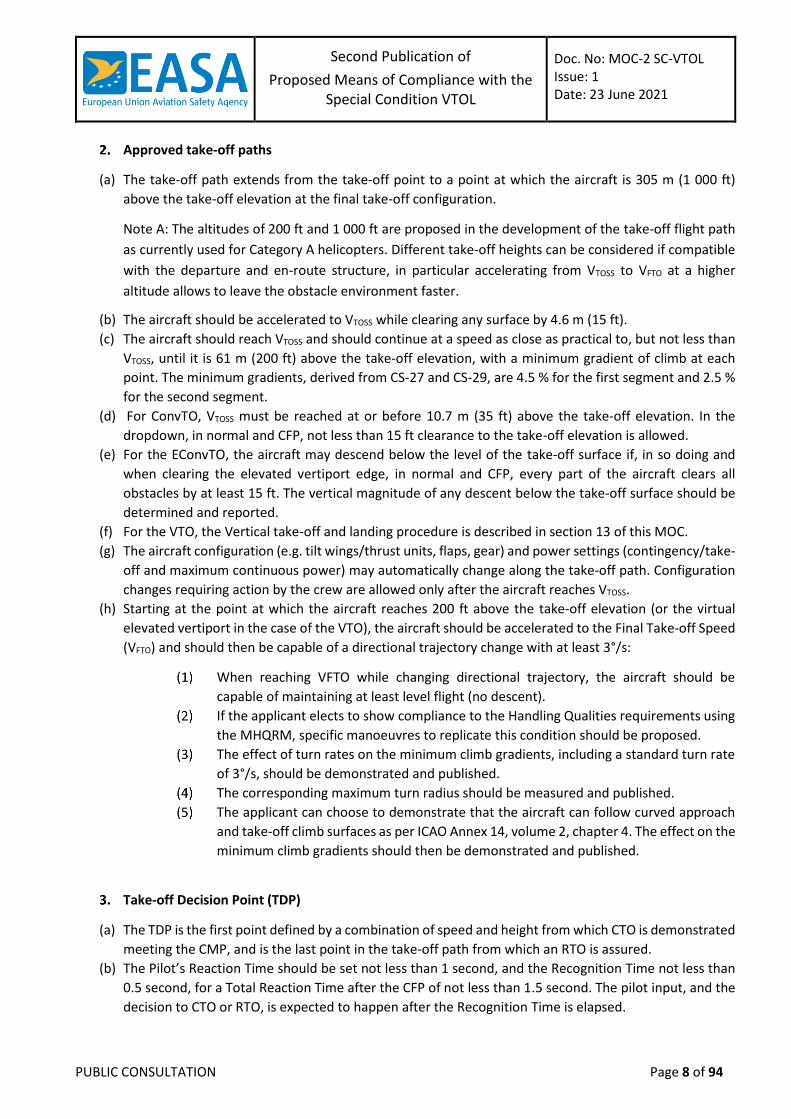
Approved take-off paths
(a) The take-off path extends from the take-off point to a point at which the aircraft is 305 m (1 000 ft)
above the take-off elevation at the final take-off configuration.
Note A: The altitudes of 200 ft and 1 000 ft are proposed in the development of the take-off flight path
as currently used for Category A helicopters. Different take-off heights can be considered if compatible
with the departure and en-route structure, in particular accelerating from VTOSS to VFTO at a higher
altitude allows to leave the obstacle environment faster.
(b) The aircraft should be accelerated to VTOSS while clearing any surface by 4.6 m (15 ft).
(c) The aircraft should reach VTOSS and should continue at a speed as close as practical to, but not less than
VTOSS, until it is 61 m (200 ft) above the take-off elevation, with a minimum gradient of climb at each
point. The minimum gradients, derived from CS-27 and CS-29, are 4.5 % for the first segment and 2.5 %
for the second segment.
(d) For ConvTO, VTOSS must be reached at or before 10.7 m (35 ft) above the take-off elevation. In the
dropdown, in normal and CFP, not less than 15 ft clearance to the take-off elevation is allowed.
(e) For the EConvTO, the aircraft may descend below the level of the take-off surface if, in so doing and
when clearing the elevated vertiport edge, in normal and CFP, every part of the aircraft clears all
obstacles by at least 15 ft. The vertical magnitude of any descent below the take-off surface should be
determined and reported.
(f) For the VTO, the Vertical take-off and landing procedure is described in section 13 of this MOC.
(g) The aircraft configuration (e.g. tilt wings/thrust units, flaps, gear) and power settings (contingency/take-
off and maximum continuous power) may automatically change along the take-off path. Configuration
changes requiring action by the crew are allowed only after the aircraft reaches VTOSS.
(h) Starting at the point at which the aircraft reaches 200 ft above the take-off elevation (or the virtual
elevated vertiport in the case of the VTO), the aircraft should be accelerated to the Final Take-off Speed
(VFTO) and should then be capable of a directional trajectory change with at least 3°/s:
When reaching VFTO while changing directional trajectory, the aircraft should be
capable of maintaining at least level flight (no descent).
If the applicant elects to show compliance to the Handling Qualities requirements using
the MHQRM, specific manoeuvres to replicate this condition should be proposed.
The effect of turn rates on the minimum climb gradients, including a standard turn rate
of 3°/s, should be demonstrated and published.
The corresponding maximum turn radius should be measured and published.
The applicant can choose to demonstrate that the aircraft can follow curved approach
and take-off climb surfaces as per ICAO Annex 14, volume 2, chapter 4. The effect on the
minimum climb gradients should then be demonstrated and published.
Take-off Decision Point (TDP)
(a) The TDP is the first point defined by a combination of speed and height from which CTO is demonstrated
meeting the CMP, and is the last point in the take-off path from which an RTO is assured.
(b) The Pilot’s Reaction Time should be set not less than 1 second, and the Recognition Time not less than
0.5 second, for a Total Reaction Time after the CFP of not less than 1.5 second. The pilot input, and the
decision to CTO or RTO, is expected to happen after the Recognition Time is elapsed.
Second Publication of
Proposed Means of Compliance with the Special Condition VTOL
Doc. No: MOC-2 SC-VTOL Issue: 1 Date: 23 June 2021
PUBLIC CONSULTATION Page 9 of 94
Note: The take-off performance must be determined for all associated mass, atmospheric and wind
conditions (see MOC VTOL.2105) so that, in case of the occurrence of the CFP event at any time after the
start of take-off, the aircraft can either return to, and stop safely on the take-off area, or continue the take-
off and climb out.
Take-off Safety Speed (VTOSS)
(a) Only primary controls should be used while attaining VTOSS and while establishing the required climb
gradient.
(b) VTOSS should be reached without requiring configuration changes commanded by the crew.
(c) VTOSS should be demonstrated for each weight, most critical centre of gravity position, altitude, and
temperature for which take-off data are to be determined.
(d) Flying at VTOSS should provide a steady gradient of climb of at least 4.5 % at the power rate setting
declared by the applicant for the first take-off segment.
Final Take-off Speed (VFTO)
(a) Any control can be used while attaining VFTO and while establishing the required climb gradient.
(b) VFTO can be reached and maintained requiring configuration changes, including landing gear retraction,
commanded by the crew.
(c) VFTO should be demonstrated for each weight, most critical centre of gravity position, altitude, and
temperature for which take-off data are to be determined.
(d) Flying at VFTO should provide a steady gradient of climb of at least 2.5 % at maximum continuous power
and a manoeuvring capability of not less than 3°/s of turn rate while not descending.
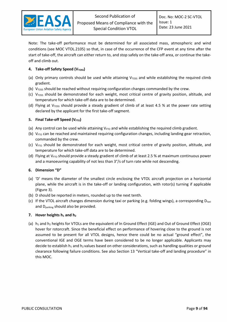
Dimension “D”
(a) ‘D’ means the diameter of the smallest circle enclosing the VTOL aircraft projection on a horizontal
plane, while the aircraft is in the take-off or landing configuration, with rotor(s) turning if applicable
(Figure 3).
(b) D should be reported in meters, rounded up to the next tenth.
(c) If the VTOL aircraft changes dimension during taxi or parking (e.g. folding wings), a corresponding Dtaxi
and Dparking should also be provided.
Hover heights h1 and h2
(a) h1 and h2 heights for VTOLs are the equivalent of In Ground Effect (IGE) and Out of Ground Effect (OGE)
hover for rotorcraft. Since the beneficial effect on performance of hovering close to the ground is not
assumed to be present for all VTOL designs, hence there could be no actual “ground effect”, the
conventional IGE and OGE terms have been considered to be no longer applicable. Applicants may
decide to establish h1 and h2 values based on other considerations, such as handling qualities or ground
clearance following failure conditions. See also Section 13 “Vertical take-off and landing procedure” in
this MOC.
Second Publication of
Proposed Means of Compliance with the Special Condition VTOL
Doc. No: MOC-2 SC-VTOL Issue: 1 Date: 23 June 2021
PUBLIC CONSULTATION Page 10 of 94
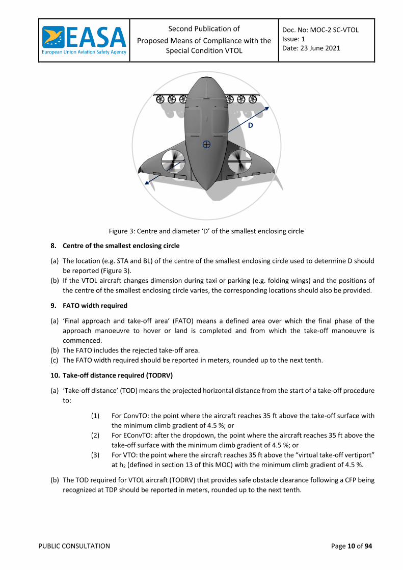
Figure 3: Centre and diameter ‘D’ of the smallest enclosing circle
Centre of the smallest enclosing circle
(a) The location (e.g. STA and BL) of the centre of the smallest enclosing circle used to determine D should
be reported (Figure 3).
(b) If the VTOL aircraft changes dimension during taxi or parking (e.g. folding wings) and the positions of
the centre of the smallest enclosing circle varies, the corresponding locations should also be provided.
FATO width required
(a) ‘Final approach and take-off area’ (FATO) means a defined area over which the final phase of the
approach manoeuvre to hover or land is completed and from which the take-off manoeuvre is
commenced.
(b) The FATO includes the rejected take-off area.
(c) The FATO width required should be reported in meters, rounded up to the next tenth.
Take-off distance required (TODRV)
(a) ‘Take-off distance’ (TOD) means the projected horizontal distance from the start of a take-off procedure
to:
For ConvTO: the point where the aircraft reaches 35 ft above the take-off surface with
the minimum climb gradient of 4.5 %; or
For EConvTO: after the dropdown, the point where the aircraft reaches 35 ft above the
take-off surface with the minimum climb gradient of 4.5 %; or
For VTO: the point where the aircraft reaches 35 ft above the “virtual take-off vertiport”
at h2 (defined in section 13 of this MOC) with the minimum climb gradient of 4.5 %.
(b) The TOD required for VTOL aircraft (TODRV) that provides safe obstacle clearance following a CFP being
recognized at TDP should be reported in meters, rounded up to the next tenth.
D
Second Publication of
Proposed Means of Compliance with the Special Condition VTOL
Doc. No: MOC-2 SC-VTOL Issue: 1 Date: 23 June 2021
PUBLIC CONSULTATION Page 11 of 94
Rejected take-off distance required (RTODRV)
(a) ‘Rejected take-off distance’ (RTOD) means the length of the FATO declared available and suitable for
VTOL aircraft to complete a rejected take-off in accordance with the Category in which it is operated,
Enhanced or Basic.
(b) The RTOD required for VTOL aircraft (RTODRV) that provides safe containment following a CFP being
recognized at TDP should be reported in meters, rounded up to the next tenth.
TLOF size required
(a) ‘Touchdown and lift-off area’ (TLOF) means an area on which a VTOL aircraft may touch down or lift off.
(b) The TLOF size (length and width) required for approved procedures should be reported in meters,
rounded up to the next tenth.
(c) The minimum dimensions should be the larger of:
the minimum size of the surface to contain the undercarriage;
the aircraft performance scatter during a landing after a Critical Failure for Performance
(CFP) to a specific reference point; and
the surface required to provide the minimum suitable visual cues for a landing after a
CFP.
Vertical take-off and landing procedure
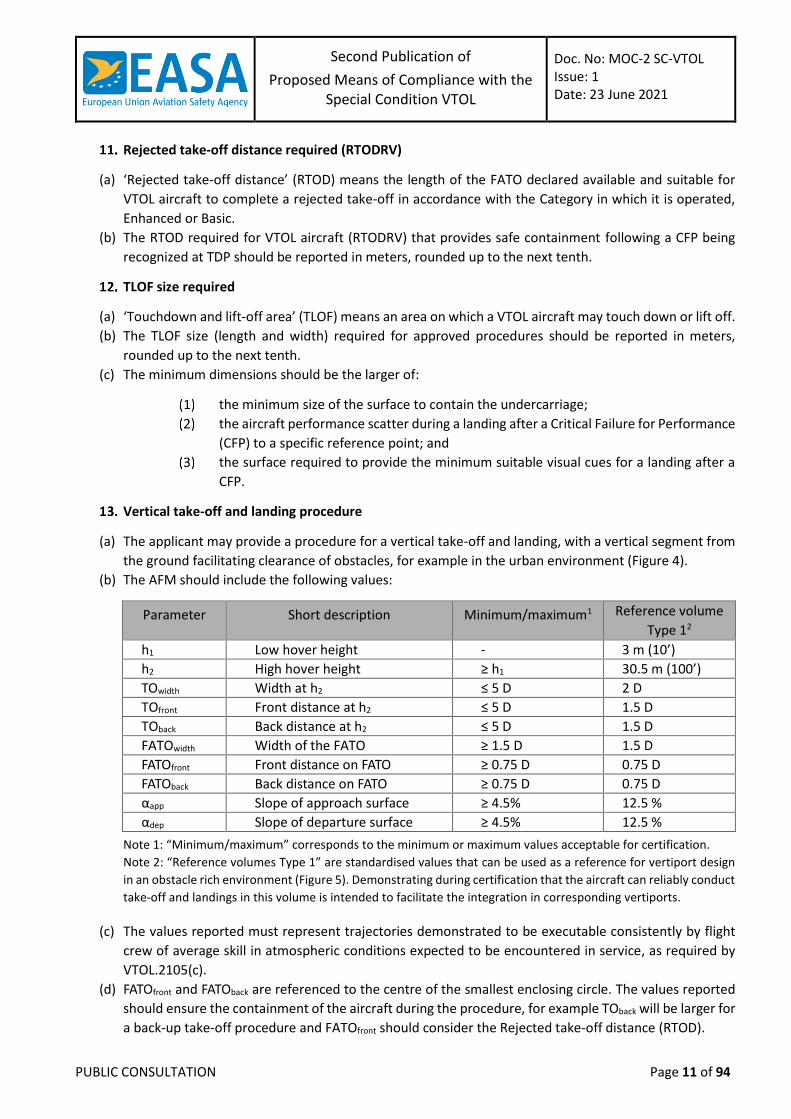
(a) The applicant may provide a procedure for a vertical take-off and landing, with a vertical segment from
the ground facilitating clearance of obstacles, for example in the urban environment (Figure 4).
(b) The AFM should include the following values:
Parameter Short description Minimum/maximum1 Reference volume
Type 12
h1 Low hover height - 3 m (10’)
h2 High hover height ≥ h1 30.5 m (100’)
TOwidth Width at h2 ≤ 5 D 2 D
TOfront Front distance at h2 ≤ 5 D 1.5 D
TOback Back distance at h2 ≤ 5 D 1.5 D
FATOwidth Width of the FATO ≥ 1.5 D 1.5 D
FATOfront Front distance on FATO ≥ 0.75 D 0.75 D
FATOback Back distance on FATO ≥ 0.75 D 0.75 D
αapp Slope of approach surface ≥ 4.5% 12.5 %
αdep Slope of departure surface ≥ 4.5% 12.5 %
Note 1: “Minimum/maximum” corresponds to the minimum or maximum values acceptable for certification.
Note 2: “Reference volumes Type 1” are standardised values that can be used as a reference for vertiport design
in an obstacle rich environment (Figure 5). Demonstrating during certification that the aircraft can reliably conduct
take-off and landings in this volume is intended to facilitate the integration in corresponding vertiports.
(c) The values reported must represent trajectories demonstrated to be executable consistently by flight
crew of average skill in atmospheric conditions expected to be encountered in service, as required by
VTOL.2105(c).
(d) FATOfront and FATOback are referenced to the centre of the smallest enclosing circle. The values reported
should ensure the containment of the aircraft during the procedure, for example TOback will be larger for
a back-up take-off procedure and FATOfront should consider the Rejected take-off distance (RTOD).
Second Publication of
Proposed Means of Compliance with the Special Condition VTOL
Doc. No: MOC-2 SC-VTOL Issue: 1 Date: 23 June 2021
PUBLIC CONSULTATION Page 12 of 94
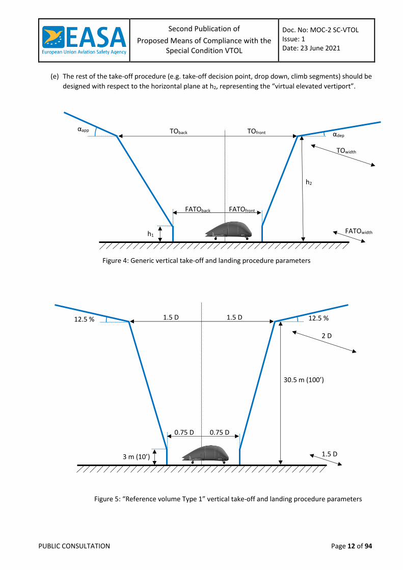
(e) The rest of the take-off procedure (e.g. take-off decision point, drop down, climb segments) should be
designed with respect to the horizontal plane at h2, representing the “virtual elevated vertiport”.
Figure 4: Generic vertical take-off and landing procedure parameters
Figure 5: “Reference volume Type 1” vertical take-off and landing procedure parameters
αdep αapp
h1
FATOback
TOback TOfront
FATOfront
TOwidth
FATOwidth
h2
30.5 m (100’)
0.75 D
1.5 D 1.5 D
0.75 D
3 m (10’) 1.5 D
2 D
12.5 % 12.5 %
Second Publication of
Proposed Means of Compliance with the Special Condition VTOL
Doc. No: MOC-2 SC-VTOL Issue: 1 Date: 23 June 2021
PUBLIC CONSULTATION Page 13 of 94
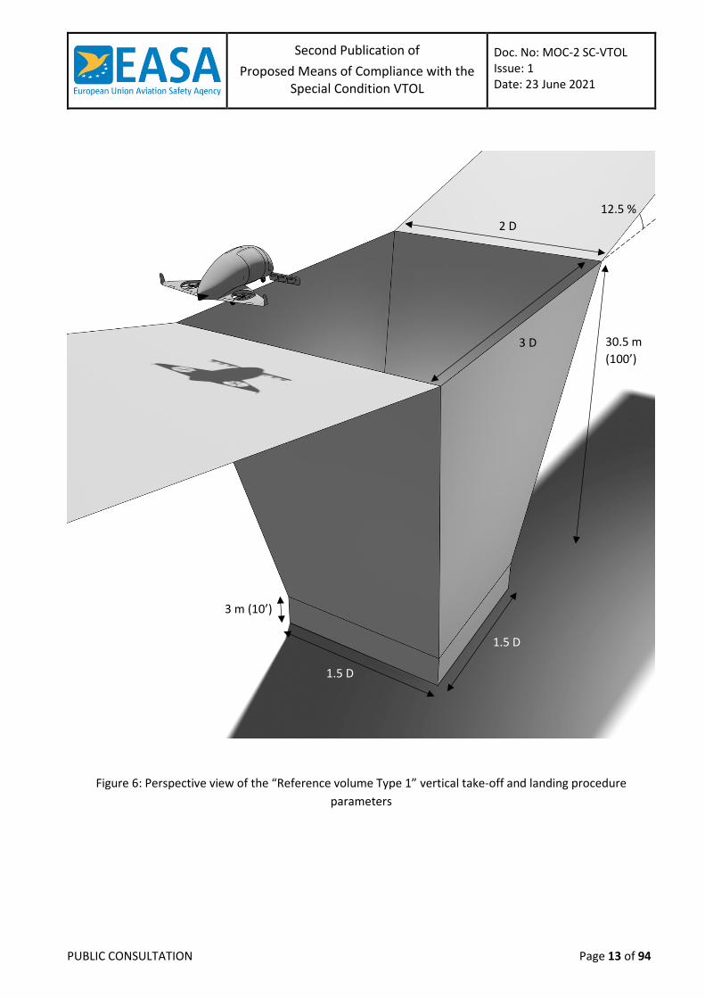
Figure 6: Perspective view of the “Reference volume Type 1” vertical take-off and landing procedure
parameters
3 m (10’)
30.5 m
(100’)
2 D
3 D
1.5 D
1.5 D
12.5 %
Second Publication of
Proposed Means of Compliance with the Special Condition VTOL
Doc. No: MOC-2 SC-VTOL Issue: 1 Date: 23 June 2021
PUBLIC CONSULTATION Page 14 of 94
Overall width
(a) ‘Overall width’ means the largest width of the VTOL aircraft projection on a horizontal plane, while the
aircraft is in the take-off or landing configuration, with rotor(s) turning if applicable.
(b) The overall width should be reported in meters, rounded up to the next tenth.
(c) If the VTOL aircraft width changes during taxi or parking (e.g. folding wings), a corresponding overall
width during taxi or parking should also be provided.
Overall length
(a) ‘Overall length’ means the largest length of the VTOL aircraft projection on a horizontal plane, while the
aircraft is in the take-off or landing configuration, with rotor(s) turning if applicable.
(b) The overall length should be reported in meters, rounded up to the next tenth.
(c) If the VTOL aircraft length changes during taxi or parking (e.g. retracting tail), a corresponding overall
length during taxi or parking should also be provided.
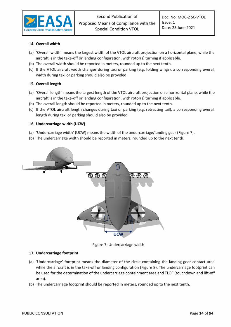
Undercarriage width (UCW)
(a) ‘Undercarriage width’ (UCW) means the width of the undercarriage/landing gear (Figure 7).
(b) The undercarriage width should be reported in meters, rounded up to the next tenth.
Figure 7: Undercarriage width
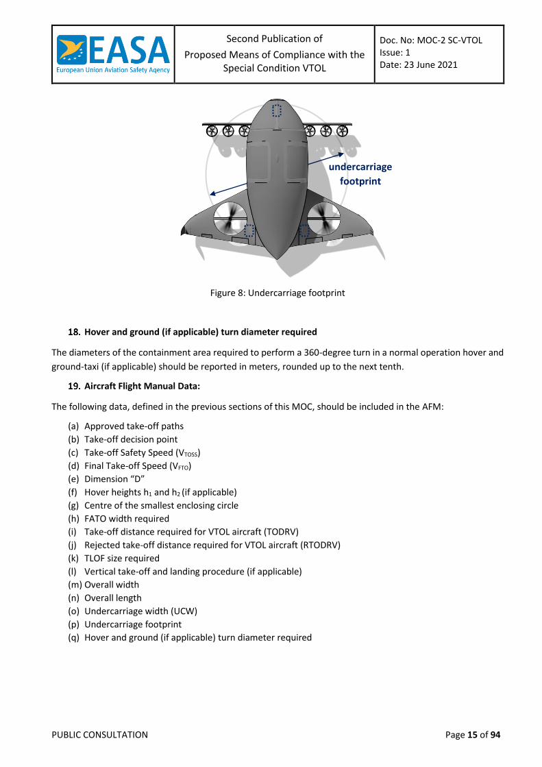
Undercarriage footprint
(a) ‘Undercarriage’ footprint means the diameter of the circle containing the landing gear contact area
while the aircraft is in the take-off or landing configuration (Figure 8). The undercarriage footprint can
be used for the determination of the undercarriage containment area and TLOF (touchdown and lift-off
area).
(b) The undercarriage footprint should be reported in meters, rounded up to the next tenth.
UCW
Second Publication of
Proposed Means of Compliance with the Special Condition VTOL
Doc. No: MOC-2 SC-VTOL Issue: 1 Date: 23 June 2021
PUBLIC CONSULTATION Page 15 of 94
undercarriage
footprint
Figure 8: Undercarriage footprint
Hover and ground (if applicable) turn diameter required
The diameters of the containment area required to perform a 360-degree turn in a normal operation hover and
ground-taxi (if applicable) should be reported in meters, rounded up to the next tenth.
Aircraft Flight Manual Data:
The following data, defined in the previous sections of this MOC, should be included in the AFM:
(a) Approved take-off paths
(b) Take-off decision point
(c) Take-off Safety Speed (VTOSS)
(d) Final Take-off Speed (VFTO)
(e) Dimension “D”
(f) Hover heights h1 and h2 (if applicable)
(g) Centre of the smallest enclosing circle
(h) FATO width required
(i) Take-off distance required for VTOL aircraft (TODRV)
(j) Rejected take-off distance required for VTOL aircraft (RTODRV)
(k) TLOF size required
(l) Vertical take-off and landing procedure (if applicable)
(m) Overall width
(n) Overall length
(o) Undercarriage width (UCW)
(p) Undercarriage footprint
(q) Hover and ground (if applicable) turn diameter required
Second Publication of
Proposed Means of Compliance with the Special Condition VTOL
Doc. No: MOC-2 SC-VTOL Issue: 1 Date: 23 June 2021
PUBLIC CONSULTATION Page 16 of 94
MOC VTOL.2120 Climb requirements
For Category Enhanced, the climb gradient without ground effect, 305 m (1 000 ft) above the take-off surface,
should be at least 2.5 %, for each weight, altitude, and temperature for which take-off data are to be determined,
and for the duration of the flight:
(a) following a critical failure for performance (CFP) and with the remaining lift/thrust engines at maximum
continuous power, if approved, or at take-off power for aircraft for which certification for use of take-
off power is requested; and
(b) with the landing gear retracted and the aircraft in cruise configuration; and
(c) at the speed selected by the applicant.
Note: The altitude of 1 000 ft is proposed as currently used for Category A helicopters. Different cruise
altitude can be considered if compatible with the departure and en-route structure.
See MOC VTOL.2115 and 2130 for specific climb requirements for take-off and balked landing.
MOC VTOL.2130 Landing
This MOC does not cover the approach before the landing and starts from a point at which the decision to land,
from an operational point of view, has been taken.
Landing procedures
The landing can be of two main types a Conventional Landing (ConvL) and a Vertical Landing (VL):
(a) A ConvL path starts at a Landing Decision Point (LDP, see below) until the point in which the aircraft
reaches a complete stop. The trajectory may have the most appropriate glide path foreseen by the
applicant.
(b) A VL might be required to comply with obstacle separation when landing in a Vertiport in an Urban Air
Mobility (UAM) environment. The applicant may choose to have, from a point along the approach after
the LDP, a pure vertical trajectory. The maximum deviations from this nominal trajectory should be
determined. See MOC VTOL.2115 “Vertical take-off and landing procedure” for more details.
Landing decision point (LDP)
(a) The characteristic point along the landing flight path is the Landing Decision Point (LDP), which is defined
as the last point from which a balked landing can be performed. After LDP a balked landing is not
assured.
(b) If the aircraft is required to show continued safe flight and landing, then a landing should be possible
following a CFP before or after the LDP.
(c) LDP should be identified with a combination of height, vertical speed and airspeed and/or ground speed.
(d) LDP could be reached at a speed equal or lower to VREF.
Landing reference Speed (VREF)
The landing reference speed is the speed determined at the maximum flight Glide Path Angle (GPA) for which
certification is sought and with all lift/thrust systems operative that:
(a) allows for speed variations during a landing in expected turbulence and all reasonably expected
environmental conditions; and
Second Publication of
Proposed Means of Compliance with the Special Condition VTOL
Doc. No: MOC-2 SC-VTOL Issue: 1 Date: 23 June 2021
PUBLIC CONSULTATION Page 17 of 94
(b) provides enough manoeuvring capability; and
(c) is the initial speed that should be used to determine the area required to land and come to a stop.
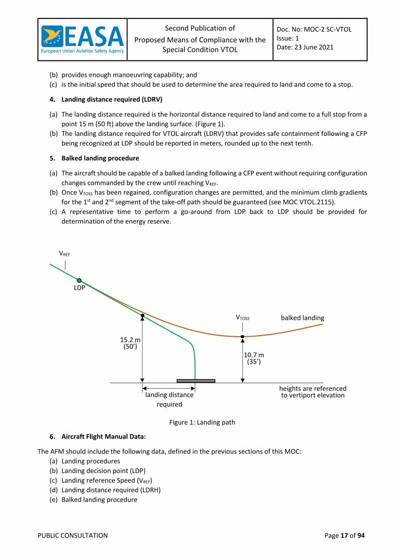
Landing distance required (LDRV)
(a) The landing distance required is the horizontal distance required to land and come to a full stop from a
point 15 m (50 ft) above the landing surface. (Figure 1).
(b) The landing distance required for VTOL aircraft (LDRV) that provides safe containment following a CFP
being recognized at LDP should be reported in meters, rounded up to the next tenth.
Balked landing procedure
(a) The aircraft should be capable of a balked landing following a CFP event without requiring configuration
changes commanded by the crew until reaching VREF.
(b) Once VTOSS has been regained, configuration changes are permitted, and the minimum climb gradients
for the 1st and 2nd segment of the take-off path should be guaranteed (see MOC VTOL.2115).
(c) A representative time to perform a go-around from LDP back to LDP should be provided for
determination of the energy reserve.
Figure 1: Landing path
Aircraft Flight Manual Data:
The AFM should include the following data, defined in the previous sections of this MOC:
(a) Landing procedures
(b) Landing decision point (LDP)
(c) Landing reference Speed (VREF)
(d) Landing distance required (LDRH)
(e) Balked landing procedure
LDP
15.2 m (50’)
VREF
10.7 m (35’)
balked landing VTOSS
landing distance
required
heights are referenced to vertiport elevation
Second Publication of
Proposed Means of Compliance with the Special Condition VTOL
Doc. No: MOC-2 SC-VTOL Issue: 1 Date: 23 June 2021
PUBLIC CONSULTATION Page 18 of 94
MOC – SUBPART C – STRUCTURES
MOC VTOL.2205 Interaction of systems and structures
General
The following criteria should be used for compliance with VTOL.2205 for aircraft equipped with flight control
systems, autopilots, stability augmentation systems, load alleviation systems, flutter control systems, fuel
management systems and any other system the failure of which could affect the load condition or aeroelasticity
characteristics of the aircraft. If this MOC is used for other systems, it may be necessary to adapt the criteria to
the specific system.
(a) The criteria defined herein only address the direct structural consequences of the system responses
and performances and cannot be considered in isolation but should be included in the overall safety
evaluation of the aircraft. These criteria may in some instances duplicate standards already established
for this evaluation. These criteria are applicable to any structure the loading of which may be modified
by failure(s) of a system. Specific criteria that define acceptable limits on handling characteristics or
stability requirements when operating in the system degraded or inoperative mode are not provided in
this MOC.
(b) Depending upon the specific characteristics of the aircraft, additional studies may be required that go
beyond the criteria provided in this appendix in order to demonstrate the capability of the aircraft to
meet other realistic conditions such as alternative gust or manoeuvre descriptions for an aircraft
equipped with a load alleviation system.
(c) The following definitions are applicable to this MOC.
Structural performance: Capability of the aircraft to meet the structural requirements of SC-
VTOL.
Flight limitations: Limitations that can be applied to the aircraft flight conditions following
an in-flight occurrence and that are included in the flight manual (e.g., speed limitations,
avoidance of severe weather conditions, etc.).
Operational limitations: Limitations, including flight limitations, that can be applied to the
aircraft operating conditions before dispatch (e.g., fuel, payload and Master Minimum
Equipment List limitations).
Probabilistic terms: The probabilistic terms (probable, improbable, extremely improbable)
used in this MOC are the same as those used in MOC VTOL.2510.
Failure condition: The term failure condition is the same as that used in MOC VTOL.2510,
however this MOC applies only to system failure conditions that affect the structural
performance of the aircraft (e.g., system failure conditions that induce loads, change the
response of the aircraft to inputs such as gusts or pilot actions, or lower flutter margins).
Effects of Systems on Structures
(a) General. The following criteria will be used in determining the influence of a system and its failure
conditions on the aircraft structure.
(b) System fully operative. With the system fully operative, the following apply:
Limit loads should be derived in all normal operating configurations of the system from all
the limit conditions specified in Subpart C, taking into account any special behaviour of such
a system or associated functions or any effect on the structural performance of the aircraft
Second Publication of
Proposed Means of Compliance with the Special Condition VTOL
Doc. No: MOC-2 SC-VTOL Issue: 1 Date: 23 June 2021
PUBLIC CONSULTATION Page 19 of 94
that may occur up to the limit loads. In particular, any significant nonlinearity (rate of
displacement of control surface, thresholds or any other system nonlinearities) should be
accounted for in a realistic or conservative way when deriving limit loads from limit
conditions.
The aircraft should meet the strength requirements of SC-VTOL (Static strength, residual
strength), using the specified factors to derive ultimate loads from the limit loads defined
above. The effect of nonlinearities should be investigated beyond limit conditions to ensure
the behaviour of the system presents no anomaly compared to the behaviour below limit
conditions. However, conditions beyond limit conditions need not be considered when it
can be shown that the aircraft has design features that will not allow it to exceed those limit
conditions.
The aircraft should meet the aeroelastic stability requirements of VTOL.2245
(c) System in the failure condition. For any system failure condition not shown to be extremely improbable,
the following apply:
At the time of occurrence. At the time of failure, the aircraft should be evaluated in 1-g level
flight and also the most critical flight condition from the usage spectrum defined under MOC
VTOL.2240(a)(b). Starting from these flight conditions, a realistic scenario, including pilot
corrective actions, should be established to determine the loads occurring at the time of
failure and immediately after failure.
Note: Flight conditions may be excluded from the evaluation, if the probability of
occurrence of the failure mode combined with the probability of being in the flight
condition is shown to be extremely improbable.
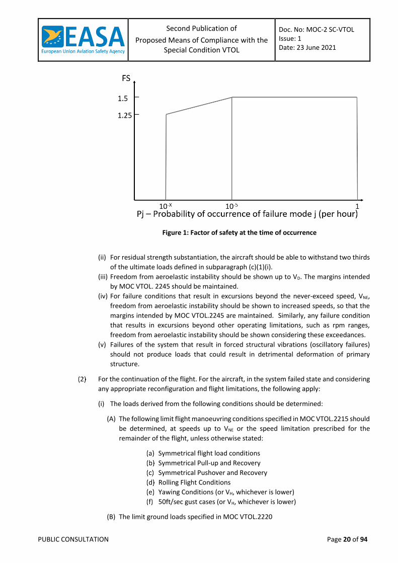
(i) For static strength substantiation, these loads, multiplied by an appropriate factor of
safety that is related to the probability of occurrence of the failure, are ultimate loads
to be considered for design. The factor of safety (F.S.) is defined in Figure 1 where 10-X
is equal to the probability associated to Extremely Improbable for the aircraft Category
and number of passengers in accordance with MOC VTOL.2510.
Second Publication of
Proposed Means of Compliance with the Special Condition VTOL
Doc. No: MOC-2 SC-VTOL Issue: 1 Date: 23 June 2021
PUBLIC CONSULTATION Page 20 of 94
Figure 1: Factor of safety at the time of occurrence
(ii) For residual strength substantiation, the aircraft should be able to withstand two thirds
of the ultimate loads defined in subparagraph (c)(1)(i).
(iii) Freedom from aeroelastic instability should be shown up to VD. The margins intended
by MOC VTOL. 2245 should be maintained.
(iv) For failure conditions that result in excursions beyond the never-exceed speed, VNE,
freedom from aeroelastic instability should be shown to increased speeds, so that the
margins intended by MOC VTOL.2245 are maintained. Similarly, any failure condition
that results in excursions beyond other operating limitations, such as rpm ranges,
freedom from aeroelastic instability should be shown considering these exceedances.
(v) Failures of the system that result in forced structural vibrations (oscillatory failures)
should not produce loads that could result in detrimental deformation of primary
structure.
For the continuation of the flight. For the aircraft, in the system failed state and considering
any appropriate reconfiguration and flight limitations, the following apply:
(i) The loads derived from the following conditions should be determined:
(A) The following limit flight manoeuvring conditions specified in MOC VTOL.2215 should
be determined, at speeds up to VNE or the speed limitation prescribed for the
remainder of the flight, unless otherwise stated:
Symmetrical flight load conditions
Symmetrical Pull-up and Recovery
Symmetrical Pushover and Recovery
Rolling Flight Conditions
Yawing Conditions (or VH, whichever is lower)
50ft/sec gust cases (or VH, whichever is lower)
(B) The limit ground loads specified in MOC VTOL.2220
Second Publication of
Proposed Means of Compliance with the Special Condition VTOL
Doc. No: MOC-2 SC-VTOL Issue: 1 Date: 23 June 2021
PUBLIC CONSULTATION Page 21 of 94
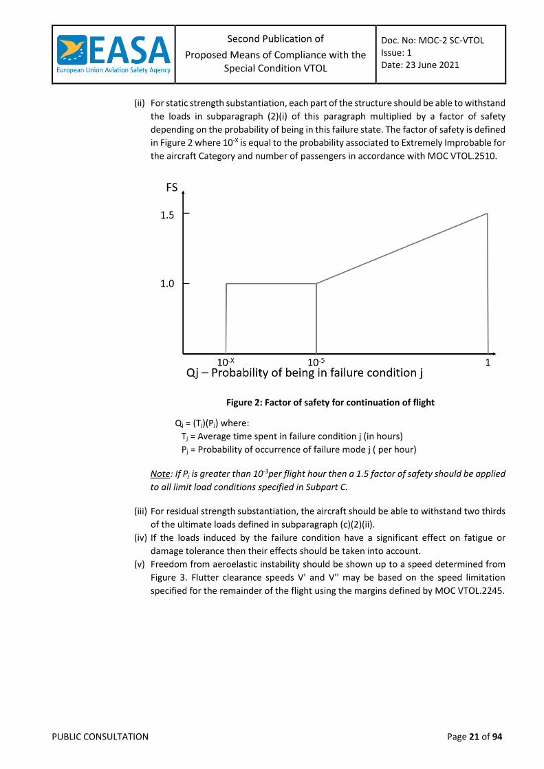
(ii) For static strength substantiation, each part of the structure should be able to withstand
the loads in subparagraph (2)(i) of this paragraph multiplied by a factor of safety
depending on the probability of being in this failure state. The factor of safety is defined
in Figure 2 where 10-X is equal to the probability associated to Extremely Improbable for
the aircraft Category and number of passengers in accordance with MOC VTOL.2510.
Figure 2: Factor of safety for continuation of flight
Qj = (Tj)(Pj) where:
Tj = Average time spent in failure condition j (in hours)
Pj = Probability of occurrence of failure mode j ( per hour)
Note: If Pj is greater than 10-3per flight hour then a 1.5 factor of safety should be applied
to all limit load conditions specified in Subpart C.
(iii) For residual strength substantiation, the aircraft should be able to withstand two thirds
of the ultimate loads defined in subparagraph (c)(2)(ii).
(iv) If the loads induced by the failure condition have a significant effect on fatigue or
damage tolerance then their effects should be taken into account.
(v) Freedom from aeroelastic instability should be shown up to a speed determined from
Figure 3. Flutter clearance speeds V' and V'' may be based on the speed limitation
specified for the remainder of the flight using the margins defined by MOC VTOL.2245.
Second Publication of
Proposed Means of Compliance with the Special Condition VTOL
Doc. No: MOC-2 SC-VTOL Issue: 1 Date: 23 June 2021
PUBLIC CONSULTATION Page 22 of 94
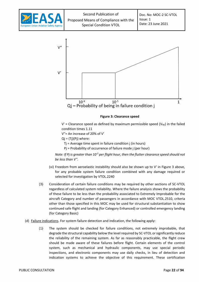
Figure 3: Clearance speed
V' = Clearance speed as defined by maximum permissible speed (VNE) in the failed
condition times 1.11
V''= An increase of 20% of V’
Qj = (Tj)(Pj) where:
Tj = Average time spent in failure condition j (in hours)
Pj = Probability of occurrence of failure mode j (per hour)
Note: If Pj is greater than 10-3 per flight hour, then the flutter clearance speed should not
be less than V''.
(vi) Freedom from aeroelastic instability should also be shown up to V' in Figure 3 above,
for any probable system failure condition combined with any damage required or
selected for investigation by VTOL.2240
Consideration of certain failure conditions may be required by other sections of SC-VTOL
regardless of calculated system reliability. Where the failure analysis shows the probability
of these failure to be less than the probability associated to Extremely Improbable for the
aircraft Category and number of passengers in accordance with MOC VTOL.2510, criteria
other than those specified in this MOC may be used for structural substantiation to show
continued safe flight and landing (for Category Enhanced) or controlled emergency landing
(for Category Basic)
(d) Failure indications. For system failure detection and indication, the following apply:
The system should be checked for failure conditions, not extremely improbable, that
degrade the structural capability below the level required by SC-VTOL or significantly reduce
the reliability of the remaining system. As far as reasonably practicable, the flight crew
should be made aware of these failures before flight. Certain elements of the control
system, such as mechanical and hydraulic components, may use special periodic
inspections, and electronic components may use daily checks, in lieu of detection and
indication systems to achieve the objective of this requirement. These certification
Second Publication of
Proposed Means of Compliance with the Special Condition VTOL
Doc. No: MOC-2 SC-VTOL Issue: 1 Date: 23 June 2021
PUBLIC CONSULTATION Page 23 of 94
maintenance requirements should be limited to components that are not readily detectable
by normal detection and indication systems and where service history shows that
inspections will provide an adequate level of safety.
The existence of any failure condition, not extremely improbable, during flight that could
significantly affect the structural capability of the aeroplane and for which the associated
reduction in airworthiness can be minimised by suitable flight limitations, should be
signalled to the flight crew. For example, failure conditions that result in a factor of safety
between the aircraft strength and the loads of Subpart C below 1.25, or flutter margins
below V", should be signalled to the crew during flight.
(e) Dispatch with known failure conditions. If the aircraft is to be dispatched in a known system failure
condition that affects structural performance, or affects the reliability of the remaining system to
maintain structural performance, then the provisions of VTOL.2205 should be met for the dispatched
condition and for subsequent failures. Flight limitations and expected operational limitations may be
taken into account in establishing Qj as the combined probability of being in the dispatched failure
condition and the subsequent failure condition for the safety margins in Figures 2 and 3. These
limitations should be such that the probability of being in this combined failure state and then
subsequently encountering limit load conditions is extremely improbable. No reduction in these safety
margins is allowed if the subsequent system failure rate is greater than 10-3 per hour.
MOC VTOL.2210 Structural Design Loads
Loads (General)
CS 27.301(b) and (c) Amdt. 6 is accepted as a means of compliance
Flight Loads (General)
CS 27.321(a) Amdt. 6 is accepted as a means of compliance
Design Fuel Loads
For aircraft with disposable fuel, the following is applicable:
(a) The disposable load combinations should include each fuel load in the range from zero fuel to the
selected maximum fuel load.
(b) If fuel is carried in the wings or other aerodynamic elements, the maximum allowable weight of the
aircraft without any fuel in this tank(s) should be established as “maximum zero wing fuel weight” or
“maximum zero ‘aerodynamic element’ fuel weight”, if it is less than the maximum weight.
(c) For Category Enhanced, a structural reserve fuel condition, not exceeding the fuel necessary for
compliance with VTOL.2430(b)(4), may be selected, considering the most critical fuel distribution. If a
structural reserve fuel condition is selected, it should be used as the minimum fuel weight condition for
showing compliance with the flight load requirements of MOC VTOL.2215 and:
The structure should be designed to withstand a condition of zero fuel in the wing or
aerodynamic element at limit loads corresponding to:
(i) 90 percent of the manoeuvring load factors defined in MOC VTOL.2200, and
(ii) Gust velocities equal to 85 percent of the values prescribed in MOC VTOL.2200.
Second Publication of
Proposed Means of Compliance with the Special Condition VTOL
Doc. No: MOC-2 SC-VTOL Issue: 1 Date: 23 June 2021
PUBLIC CONSULTATION Page 24 of 94
The durability evaluation of the structure should account for any increase in operating
stresses resulting from the design condition of (c)(1).
The flutter, deformation, and vibration requirements should also be met with zero fuel in
the wings or aerodynamic elements.
Jacking loads
CS 23.507 Amdt. 4 is accepted as a means of compliance
Mooring loads
(a) The mooring fittings and its support structure should be analysed for the loads resulting from the
maximum permissible mooring wind speed multiplied by 1.11.
(b) The wind should be considered as acting parallel to the ground in any direction to the aircraft. Ground
gust conditions should also be considered.
(c) All permissible mooring configurations, i.e. number of mooring lines and their range of angles from the
aircraft fitting, should be evaluated.
(d) The maximum wind speed and gust conditions for mooring and the permissible mooring configurations
should be published in the Aircraft Maintenance Manual.
Towing loads (towbar)
CS 23.509 Amdt. 4 is accepted as a means of compliance for towing an aircraft with the use of a towbar.
Towbarless towing (aircraft with wheeled landing gear)
(a) General
Towbarless towing vehicles are generally considered as ground equipment and are as such not subject
to direct approval by the (aircraft) certifying agencies. However, these vehicles should be qualified in
accordance with the applicable SAE ARP documents. It should be ensured that the nose landing gear
and supporting structure is not being overloaded (by static and dynamic (including fatigue) loads) during
towbarless towing operations with these vehicles. This should be ensured by the aircraft manufacturer,
either by specific investigations as described in (b) and (c) below, or alternatively, by publishing aircraft
load limitations in a towbarless towing vehicle assessment document, to allow towbarless towing
vehicle manufacturers to demonstrate their vehicles will not overload the aircraft.
(b) Limit static load cases
For the limit static load cases, the investigation may be conducted by rational analysis
supported by test evidence.
The investigation should take into account the influence on the towing loads of the tractive
force of the towing vehicle including consideration of its weight and pavement roughness.
The investigation should include all towbarless towing operation scenarios.
Operations that are explicitly prohibited need not to be addressed.
(c) Durability evaluation
Durability evaluation of the impact of towbarless towing on the airframe should be
conducted under the provision of VTOL.2240.
The contribution of the towbarless towing operational loads to the fatigue load spectra for
the nose landing gear and its support structure needs to be evaluated.
Second Publication of
Proposed Means of Compliance with the Special Condition VTOL
Doc. No: MOC-2 SC-VTOL Issue: 1 Date: 23 June 2021
PUBLIC CONSULTATION Page 25 of 94
The impact of the towbarless towing on the certified life limits of the landing gear and
supporting structure should be determined.
The fatigue spectra used in the evaluation should:
(i) consist of typical service loads encountered during towbarless towing operations, which
cover the loading scenarios noted above for static considerations, and
(ii) be based on measured statistical data derived from simulated service operation or from
applicable industry studies.
(d) Other considerations
Specific combinations of towbarless towing vehicle(s) and aircraft that have been assessed
as described above and have been found to be acceptable, along with any applicable towing
instructions and/or limitations should be specified in the Instructions for Continued
Airworthiness and in the Aircraft Flight Manual.
Aircraft braking, while the aircraft is under tow, may result in loads exceeding the aircraft’s
design load and may result in structural damage and/or nose gear collapse. For these
reasons, the aircraft manufacturer should ensure that the appropriate information is
provided in the Aircraft Maintenance Manual and in the Aircraft Flight Manual to preclude
aircraft braking during normal towbarless towing. Appropriate information should also be
provided in the Instructions for Continued Airworthiness to inspect the affected structure
should aircraft braking occur, for example in an emergency situation.
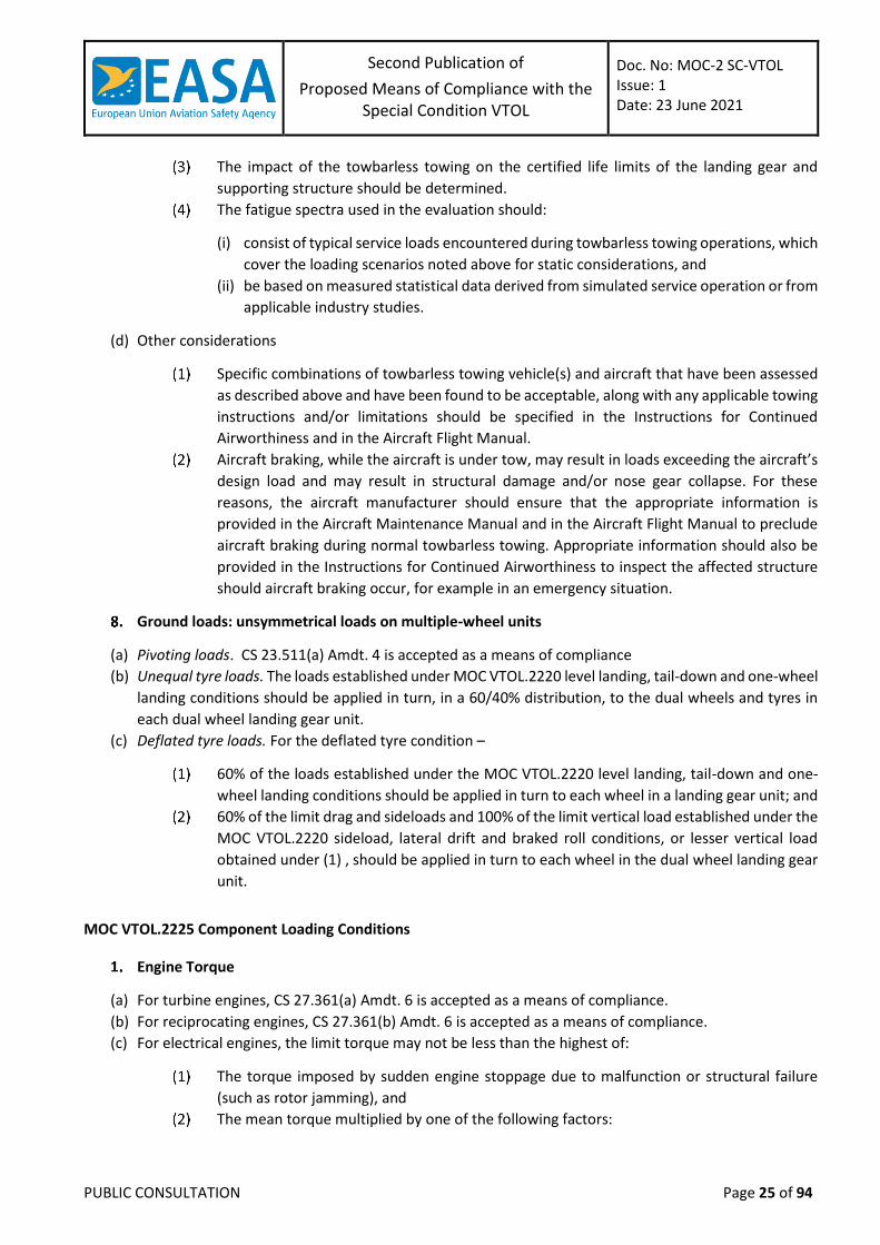
Ground loads: unsymmetrical loads on multiple-wheel units
(a) Pivoting loads. CS 23.511(a) Amdt. 4 is accepted as a means of compliance
(b) Unequal tyre loads. The loads established under MOC VTOL.2220 level landing, tail-down and one-wheel
landing conditions should be applied in turn, in a 60/40% distribution, to the dual wheels and tyres in
each dual wheel landing gear unit.
(c) Deflated tyre loads. For the deflated tyre condition –
60% of the loads established under the MOC VTOL.2220 level landing, tail-down and one-
wheel landing conditions should be applied in turn to each wheel in a landing gear unit; and
60% of the limit drag and sideloads and 100% of the limit vertical load established under the
MOC VTOL.2220 sideload, lateral drift and braked roll conditions, or lesser vertical load
obtained under (1) , should be applied in turn to each wheel in the dual wheel landing gear
unit.
MOC VTOL.2225 Component Loading Conditions
Engine Torque
(a) For turbine engines, CS 27.361(a) Amdt. 6 is accepted as a means of compliance.
(b) For reciprocating engines, CS 27.361(b) Amdt. 6 is accepted as a means of compliance.
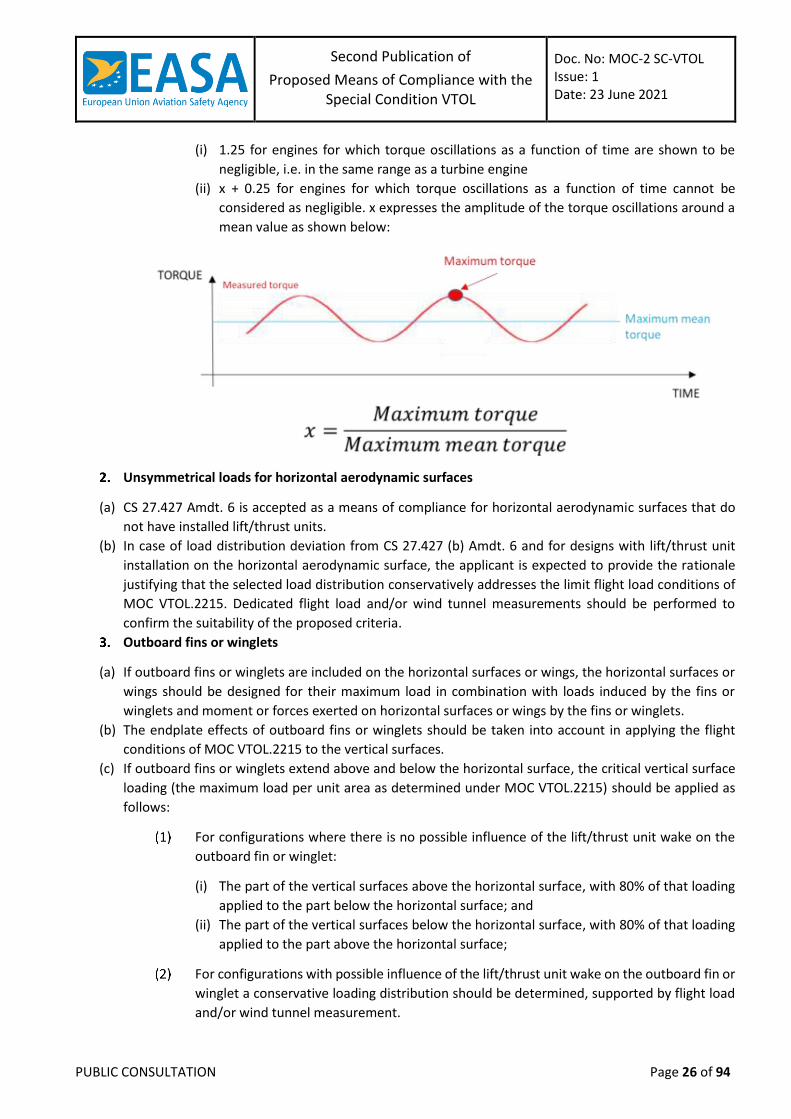
(c) For electrical engines, the limit torque may not be less than the highest of:
The torque imposed by sudden engine stoppage due to malfunction or structural failure
(such as rotor jamming), and
The mean torque multiplied by one of the following factors:
Second Publication of
Proposed Means of Compliance with the Special Condition VTOL
Doc. No: MOC-2 SC-VTOL Issue: 1 Date: 23 June 2021
PUBLIC CONSULTATION Page 26 of 94
(i) 1.25 for engines for which torque oscillations as a function of time are shown to be
negligible, i.e. in the same range as a turbine engine
(ii) x + 0.25 for engines for which torque oscillations as a function of time cannot be
considered as negligible. x expresses the amplitude of the torque oscillations around a
mean value as shown below:
Unsymmetrical loads for horizontal aerodynamic surfaces
(a) CS 27.427 Amdt. 6 is accepted as a means of compliance for horizontal aerodynamic surfaces that do
not have installed lift/thrust units.
(b) In case of load distribution deviation from CS 27.427 (b) Amdt. 6 and for designs with lift/thrust unit
installation on the horizontal aerodynamic surface, the applicant is expected to provide the rationale
justifying that the selected load distribution conservatively addresses the limit flight load conditions of
MOC VTOL.2215. Dedicated flight load and/or wind tunnel measurements should be performed to
confirm the suitability of the proposed criteria.
Outboard fins or winglets
(a) If outboard fins or winglets are included on the horizontal surfaces or wings, the horizontal surfaces or
wings should be designed for their maximum load in combination with loads induced by the fins or
winglets and moment or forces exerted on horizontal surfaces or wings by the fins or winglets.
(b) The endplate effects of outboard fins or winglets should be taken into account in applying the flight
conditions of MOC VTOL.2215 to the vertical surfaces.
(c) If outboard fins or winglets extend above and below the horizontal surface, the critical vertical surface
loading (the maximum load per unit area as determined under MOC VTOL.2215) should be applied as
follows:
For configurations where there is no possible influence of the lift/thrust unit wake on the
outboard fin or winglet:
(i) The part of the vertical surfaces above the horizontal surface, with 80% of that loading
applied to the part below the horizontal surface; and
(ii) The part of the vertical surfaces below the horizontal surface, with 80% of that loading
applied to the part above the horizontal surface;
For configurations with possible influence of the lift/thrust unit wake on the outboard fin or
winglet a conservative loading distribution should be determined, supported by flight load
and/or wind tunnel measurement.
Second Publication of
Proposed Means of Compliance with the Special Condition VTOL
Doc. No: MOC-2 SC-VTOL Issue: 1 Date: 23 June 2021
PUBLIC CONSULTATION Page 27 of 94
Special Devices
CS 23.459 Amdt. 4 is accepted as a means of compliance.
MOC VTOL.2240 (a) and (b) Structural durability
Introduction
VTOL.2240 (a) and (b) requests the applicant to perform all necessary evaluations and actions (inspection,
procedures) “to prevent structural failures due to strength degradation, which could result in serious or fatal
injuries, or extended periods of operation with reduced safety margins.”
For the category Basic, this comprises any relevant inspections or other procedures to prevent structural failure.
For the category Enhanced, this includes any relevant inspections or other procedures to detect structural
damages before failure (Damage Tolerance evaluation).
A distinction is thus made between categories Basic and Enhanced concerning durability: while both categories
have the same objective to prevent structural failures due to strength degradation, for Enhanced category the
detection of structural damage is added to VTOL.2240(a).
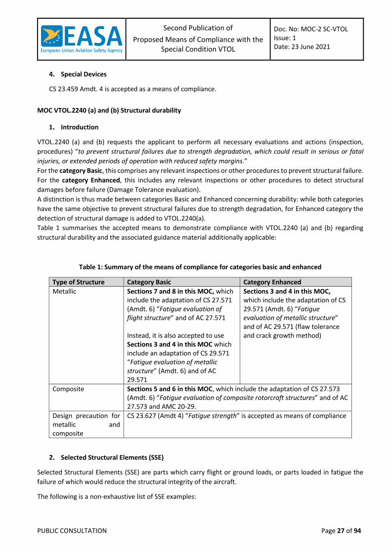
Table 1 summarises the accepted means to demonstrate compliance with VTOL.2240 (a) and (b) regarding
structural durability and the associated guidance material additionally applicable:
Table 1: Summary of the means of compliance for categories basic and enhanced
Type of Structure Category Basic Category Enhanced
Metallic Sections 7 and 8 in this MOC, which include the adaptation of CS 27.571 (Amdt. 6) “Fatigue evaluation of flight structure” and of AC 27.571 Instead, it is also accepted to use Sections 3 and 4 in this MOC which include an adaptation of CS 29.571 “Fatigue evaluation of metallic structure” (Amdt. 6) and of AC 29.571
Sections 3 and 4 in this MOC, which include the adaptation of CS 29.571 (Amdt. 6) “Fatigue evaluation of metallic structure” and of AC 29.571 (flaw tolerance and crack growth method)
Composite Sections 5 and 6 in this MOC, which include the adaptation of CS 27.573 (Amdt. 6) “Fatigue evaluation of composite rotorcraft structures” and of AC 27.573 and AMC 20-29.
Design precaution for metallic and composite
CS 23.627 (Amdt 4) “Fatigue strength” is accepted as means of compliance
Selected Structural Elements (SSE)
Selected Structural Elements (SSE) are parts which carry flight or ground loads, or parts loaded in fatigue the
failure of which would reduce the structural integrity of the aircraft.
The following is a non-exhaustive list of SSE examples:
Second Publication of
Proposed Means of Compliance with the Special Condition VTOL
Doc. No: MOC-2 SC-VTOL Issue: 1 Date: 23 June 2021
PUBLIC CONSULTATION Page 28 of 94
(a) Wing and empennage.
Control surfaces, slats, flaps, and their mechanical systems and attachments (hinges, tracks,
and fittings);
Integrally stiffened plates;
Primary fittings;
Principal splices;
Skin or reinforcement around cutouts or discontinuities;
Skin-stringer combinations;
Spar caps; and
Spar webs.
(b) Fuselage.
Frames and adjacent skin;
Door frames;
Pilot-window posts;
Structural bulkheads;
Skin and any single frame or stiffener element around a cutout;
Skin or skin splices, or both,
Door skins, frames, and latches; and
Window frames.
(c) Landing gear and their attachments.
(d) Engine mount/supports
(e) Lift Thrust Units
Rotors including blades, propeller, hubs
Rotor drive systems between the engines and the rotor hubs,
Transmission mounting
(f) Fixed and rotating control system
Means of Compliance for structural durability of metallic structures in the category Enhanced:
(a) A fatigue tolerance evaluation of each Selected Structural Element (SSE) should be performed, and
appropriate inspections and retirement time or approved equivalent means should be established to
avoid Catastrophic Failure during the operational life of the VTOL.
(b) Each SSE should be identified, as defined in Section 2 of this MOC. Additionally, any other structure
sensitive to fatigue should be evaluated.
(c) Each fatigue tolerance evaluation should include:
In-flight measurements to determine the fatigue loads or stresses for the SSEs identified in
(b) in all critical conditions throughout the range of design limitations required in MOC VTOL
2200 (including altitude effects), except that manoeuvring load factors need not exceed the
maximum values expected in operations.
The loading spectra as severe as those expected in operations based on loads or stresses
determined under (c)(1), including external load operations, if applicable, and other high
frequency power-cycle operations.
Second Publication of
Proposed Means of Compliance with the Special Condition VTOL
Doc. No: MOC-2 SC-VTOL Issue: 1 Date: 23 June 2021
PUBLIC CONSULTATION Page 29 of 94
Take-off, landing, and taxi loads when evaluating the landing gear (including skis and floats)
and other affected SSEs.
For each SSE identified in (b), a threat assessment, which includes a determination of the
probable locations, types, and sizes of damage taking into account fatigue, environmental
effects, intrinsic and discrete flaws, or accidental damage that may occur during
manufacture or operation.
A determination of the fatigue tolerance characteristics for the SSE with the damage
identified in (c)(4) that supports the inspection and retirement times, or other approved
equivalent means.
Analyses supported by test evidence and, if available, service experience.
(d) A residual strength determination should be performed that substantiates the maximum damage size
assumed in the fatigue tolerance evaluation. In determining inspection intervals based on damage
growth, the residual strength evaluation should show that the remaining structure, after damage
growth, is able to withstand design limit loads without failure.
(e) The effect of damage on stiffness, dynamic behaviour, loads and functional performance should be
considered.
(f) The inspection and retirement times or approved equivalent means established under this Section
should be included in the Airworthiness Limitation Section of the Instructions for Continued
Airworthiness required by VTOL.2625
(g) If inspections for any of the damage types identified in (c)(4) cannot be established within the limitations
of geometry, inspectability, or good design practice, then supplemental procedures, in conjunction with
the SSE retirement time, should be established to minimize the risk of occurrence of these types of
damage that could result in a catastrophic failure during the operational life of the VTOL aircraft.
(h) Discrete source damage tolerance evaluation. The aircraft should be capable of successfully completing
a flight during which likely structural damage occurs as a result of
Uncontained High-Energy Fragments and Sustained Imbalance as specified in VTOL.2240 (d)
Bird impact as specified in VTOL.2250
Additional guidance for structural durability of metallic structures in the category Enhanced:
Table 2 below provides the necessary adaptations to use AC 29.571 A and B as additional guidance for the fatigue
of metallic structures in the category Enhanced:
Table 2: Adaptations to AC 29.571 A and B for the fatigue of metallic structures in the category Enhanced
AC 29.571A. § 29.571 (Amendment 29-28) FATIGUE TOLERANCE EVALUATION OF STRUCTURE AC 29.571B. § 29.571 (Amendment 29-55) FATIGUE TOLERANCE EVALUATION OF METALLIC STRUCTURE
Original Text or reference General Changes/Adaptations
“rotorcraft” and “helicopter” To be replaced by “VTOL aircraft”
“the FAA” and “the Administrator”
To be replaced by “EASA”
“Principal Structural Element” or “PSE”
To be replaced by “Selected Structural element” or “SSE”
“§ 29.571” To be replaced by “VTOL.2240 (a) and (b)”
“Catastrophic failure” Concept not applicable to the VTOL durability objective. To be replaced by “failure”.
“§ 29.309” To be replaced by “VTOL.2200”
“§ 29.1529” To be replaced by “VTOL.2625 Instructions for Continued Airworthiness”
Second Publication of
Proposed Means of Compliance with the Special Condition VTOL
Doc. No: MOC-2 SC-VTOL Issue: 1 Date: 23 June 2021
PUBLIC CONSULTATION Page 30 of 94
AC 29.571A. § 29.571 (Amendment 29-28) FATIGUE TOLERANCE EVALUATION OF STRUCTURE
Paragraph Changes/ Adaptations in addition to the “General changes/adaptations” above
Accepted without additional changes
AC 29.571B. § 29.571 (Amendment 29-55) FATIGUE TOLERANCE EVALUATION OF METALLIC STRUCTURE
Paragraph Changes/ Adaptation in addition to the “General changes/adaptations” above
a. Purpose To be replaced by the paragraph below: “This advisory material provides additional guidance with the provisions of VTOL 2240 (a) and (b) dealing with the fatigue tolerance evaluation of VTOL metallic structure. This guidance applies to conventional metallic materials. (Corresponding guidance for composite structure can be found in AC 27.573. The fatigue evaluation procedures outlined in this advisory material are for guidance purposes only and are neither mandatory nor regulatory in nature. Although a uniform approach to fatigue tolerance evaluation is desirable, it is recognized that in such a complex area, new design features and methods of fabrication, new approaches to fatigue tolerance evaluation, and new configurations may require variations and deviations from the procedures described herein.”
d.(1) Definitions Applicable except PSE (xvi), which should be replaced by the definition of SSE provided in Section 2 of MOC VTOL.2240 (a) and (b)
d.(2).(ii) The sentence below should be removed: “Further mitigation of the sources of damage may be achieved by adoption of a critical parts plan to help ensure that the condition of the part remains as envisaged by the designer throughout its life cycle (see § 29.602). “
d.(3).(i) Selection of PSE Selected Structural Elements
The text in (i) should be replaced as follows: “Selection of SSE : All SSE, as defined in Section 2 of MOC VTOL.2240(a) and (b), should be identified. Specific areas of interest within the SSE that may require particular attention include the following:” The text in (A) to (G) remains unchanged.
d.(3).(ii) “§ 29.309” should be replaced by “VTOL.2215”
(f).(2).Identification of PSE SSE
The first sentence is deleted and should be replaced by: “The fatigue tolerance evaluation should first consider all airframe structure and structural elements, and assemblies susceptible to fatigue loading or fatigue originated from damage.”
(f).(2).(i) The first sentence is deleted, since the Failure Mode and Effects Analysis is not required for VTOL durability.
(f).(4).(i) Rotorcraft VTOL Usage Spectrum.
The following is added at the end: “The existing guidance available for flight spectrum determination are based on aeroplane/rotorcraft usage. However, considering the limited experience available on VTOL the applicant should anticipate a realistic and conservative spectrum addressing all flight phases and flight configurations conservatively. The principle to establish a VTOL spectrum can be derived from the existing guidance material”
(f).(4).(iv) To be fully replaced by “The usage spectrum should be presented to the FAA EASA for their concurrence. It should include normal operation over the range of rotorcraft VTOL configurations including a percent time under ‘external load’ conditions, in all flight phases and configurations. These should be distributed conservatively.”
(f).(4).(v) To be replaced by: “AC 27-1B MG 11, provides further detail for the development of the rotorcraft usage spectrums used in the fatigue tolerance evaluations.
Second Publication of
Proposed Means of Compliance with the Special Condition VTOL
Doc. No: MOC-2 SC-VTOL Issue: 1 Date: 23 June 2021
PUBLIC CONSULTATION Page 31 of 94
(f).(5).(ii).(F) Should be modified as follows: “Credit may be given to manufacturing, transport, handling, installation, and maintenance instructions finalized to minimize or avoid damages. Examples of these processes or instructions could be: "frozen manufacturing processes," Flight Critical Parts programs, material selection to mitigate intrinsic flaws like inclusions and defects, procedures to reduce deviations from nominal structures, etc.”
(f).(6). Inspectability and Inspection Methods.
“§ 29.1529 of the regulatory requirements.” should be replaced by “VTOL.2625 Instructions for Continued Airworthiness” The reference to “§ 29.571” should be replaced by “Section 3 (f) in MOC VTOl.2240(a) and (b)”.
(f).(6).(ii).(D) “§ 29.1529 of the regulatory requirements.” should be replaced by “VTOL.2625 Instructions for Continued Airworthiness” The reference to “§ 29.571” should be replaced by “Section 3 (e) in this MOC VTOL.2240(”.
(f).(7).(i) Retirement Times To remove : “(as required by § 29.571(d)(iii))”
Means of Compliance for structural durability of composite structures in the categories Basic and
Enhanced:
(a) Composite aircraft structure should be evaluated under the damage tolerance requirements (d) unless
the applicant establishes that a damage tolerance evaluation is impractical within the limits of geometry,
inspectability, and good design practice. In such a case, the composite aircraft structure should undergo
a fatigue evaluation in accordance with (c).
(b) Damage Tolerance Evaluation:
Damage tolerance evaluations of composite structures should show that failure due to static
and fatigue loads is avoided throughout the operational life or prescribed inspection
intervals of the VTOL aircraft.
The damage tolerance evaluation should include all SSEs, as defined in Section 2 of this
MOC.
Each damage tolerance evaluation should include:
(i) The identification of the structure being evaluated;
(ii) A determination of the structural loads or stresses for all critical conditions throughout
the range of limits in VTOL.2215 (including altitude effects), supported by in-flight and
ground measurements, except that manoeuvring load factors need not exceed the
maximum values expected in service;
(iii) The loading spectra as severe as those expected in service based on loads or stresses
determined under (b)(3)(ii), including external load operations, if applicable, and other
operations including high torque events. The occurrence distribution of all flight phases
and flight configurations should be conservatively selected.
(iv) A Threat Assessment for all structure being evaluated that specifies the locations, types,
and sizes of damage, considering fatigue, environmental effects, intrinsic and discrete
flaws, and impact or other accidental damage (including the discrete source of the
accidental damage) that may occur during manufacture or operation;
(v) An assessment of the residual strength and fatigue characteristics of all structure being
evaluated that supports the replacement times and inspection intervals established
under (b)(4); and
Second Publication of
Proposed Means of Compliance with the Special Condition VTOL
Doc. No: MOC-2 SC-VTOL Issue: 1 Date: 23 June 2021
PUBLIC CONSULTATION Page 32 of 94
(vi) allowances for the detrimental effects of material, fabrication techniques, and process
variability.
Replacement times, inspections, or other procedures should be established to require the
repair or replacement of damaged parts to prevent Catastrophic Failure. These replacement
times, inspections, or other procedures should be included in the Airworthiness Limitations
Section of the Instructions for Continued Airworthiness required by VTOL.2625 Instructions
for Continued Airworthiness.
(i) Replacement times should be determined by tests, or by analysis supported by tests to
show that throughout its life the structure is able to withstand the repeated loads of
variable magnitude expected in-service. In establishing these replacement times, the
following items should be considered:
(A) Damage identified in the Threat Assessment required by (b)(3)(iv);
(B) Maximum acceptable manufacturing defects and in-service damage (i.e., those that
do not lower the residual strength below ultimate design loads and those that can
be repaired to restore ultimate strength); and
(C) Ultimate load strength capability after applying repeated loads.
(ii) Inspection intervals should be established to reveal any damage identified in the Threat
Assessment required by (b)(3)(iv) that may occur from fatigue or other in-service causes
before such damage has grown to the extent that the component cannot sustain the
required residual strength capability. In establishing these inspection intervals, the
following items should be considered:
(A) The growth rate, including no-growth, of the damage under the repeated loads
expected in-service determined by tests or analysis supported by tests; and
(B) The required residual strength for the assumed damage established after considering
the damage type, inspection interval, detectability of damage, and the techniques
adopted for damage detection. The minimum required residual strength is the limit
load.
The effects of damage on stiffness, dynamic behaviour, loads and functional performance
should be taken into account when substantiating the maximum assumed damage size and
inspection interval.
(c) Fatigue Evaluation:
If an applicant establishes that the damage tolerance evaluation described in (b) is impractical within the limits
of geometry, inspectability, or good design practice, the applicant should do a fatigue evaluation of the particular
composite aircraft structure and:
Identify structure considered in the fatigue evaluation;
Identify the types of damage considered in the fatigue evaluation;
Establish supplemental procedures to minimise the risk of failure associated with damage
identified in (c)(2); and
Include these supplemental procedures in the Airworthiness Limitations Section of the
Instructions for Continued Airworthiness required by VTOL.2625 Instructions for Continued
Airworthiness
Second Publication of
Proposed Means of Compliance with the Special Condition VTOL
Doc. No: MOC-2 SC-VTOL Issue: 1 Date: 23 June 2021
PUBLIC CONSULTATION Page 33 of 94
(d) Discrete damage source evaluation. The aircraft should be capable of continued safe flight and landing
(for Category Enhanced) or controlled emergency landing (for Category Basic) with the likely structural
damage occurring as a result of
Uncontained High-Energy Fragments and Sustained Imbalance as specified in VTOL.2240 (d)
Bird impact as specified in VTOL.2250
Additional guidance for structural durability of composite structures in the categories Basic and
Enhanced:
Table 3 below provides the necessary adaptations to use AC 27.573 as additional guidance for fatigue of
composite structures in the categories Basic and Enhanced:
Table 3: Adaptations to AC 27.573 for the fatigue of composite structures in the categories Basic and
Enhanced
§ 27.573 (Amendment 27-47) DAMAGE TOLERANCE AND FATIGUE EVALUATION OF COMPOSITE ROTORCRAFT STRUCTURES
Original Text or reference General Changes/Adaptations
“rotorcraft” and “helicopter”
To be replaced by “VTOL aircraft”
“the FAA”, “the Administrator”, “the Rotorcraft Directorate”
To be replaced by “EASA”
“Principal Structural Element” or “PSE”
To be replaced by “Selected Structural element” or “SSE”
“§ 27.573” To be replaced by “VTOL.2240 (a) and (b)”
“Catastrophic failure” Concept not applicable to the VTOL durability objective. To be replaced by “failure”.
“§ 27.309” To be replaced by “VTOL.2200”
“§ 27.1529” To be replaced by “VTOL.2625 Instructions for Continued Airworthiness”
“AC 20-107” To be replaced by “AMC 20-29”
Paragraph Changes/ Adaptation in addition to the “General changes/adaptations” above
d (20) Design Limit loads “§ 27.301(a)” should be replaced by “VTOL.2230”
d (46) Principal Structural Element (PSE).
“PSE” should be replaced by the definition of “SSE” provided in Section 2 of MOC VTOL.2240 (a) and (b)
f. Procedures for Substantiation of Rotorcraft Composite Structure.
This paragraph is modified as follows: “The composite structures evaluation has been divided into eight basic regulatory areas to provide focus on relevant regulatory requirements. These eight areas are: fabrication requirements; basic constituent, pre-preg and laminate material acceptance requirements, and material property determination requirements; protection of structure; lightning protection; static strength evaluation; damage tolerance and fatigue evaluation; dynamic loading and response evaluation; and special repair and continued airworthiness requirements. Original as well as alternate or substitute material system constituents (e.g., fibers, resins), material systems (combinations of constituents and adhesives), and composite designs (e.g., laminates, cocured assemblies, bonded assemblies) should be qualified in accordance with the methodology presented in the following paragraphs. Each regulatory area will be addressed in turn. It is important to remember that proper certification of a composite structure is an incremental, building block process, which involves phased”
Second Publication of
Proposed Means of Compliance with the Special Condition VTOL
Doc. No: MOC-2 SC-VTOL Issue: 1 Date: 23 June 2021
PUBLIC CONSULTATION Page 34 of 94
FAA/AUTHORITY EASA involvement and incremental approval in each of the various areas outlined herein. It is recommended that an FAA/AUTHORITY certification team approach be used for composite structural substantiation. The team should consist of FAA/AUTHORITY and cognizant members of the applicant’s organization. Personnel who are composites specialists (or are otherwise knowledgeable in the subject) should be primary team member candidates. Once selected, it is recommended that team meetings be held periodically (possibly in conjunction with type boards) during certification to ensure the building block certification process is accomplished as intended. The team should assure that permanent documentation in the form of reports or other FAA/AUTHORITY acceptable documents are included in the certification data package. The documentation includes but is not limited to the structural substantiation reports (both analysis and test), manufacturing processes and quality control, and Instructions for Continued Airworthiness (maintenance, overhaul, and repair manuals). The Airworthiness Limitations Section of the Instructions for Continued Airworthiness is approved by EASA FAA engineering. Engineering practices for many of the areas identified below are available in CMH-17.”
f.(1).(v). This paragraph is modified as follows: “Alternate fabrication and process specifications should be approved and must comply with § 27.605 VTOL.2260. Any alternate specifications should provide at least the same level of quality and safety as the original specification. Any changes should be presented for FAA EASA approval well in advance of the effective date of the production change.”
f.(2). (i) to (vi) The first sentence is modified as follows: “The second area is the basic raw constituent, pre-preg and laminate material acceptance requirements, and material property determination requirements of §§ 27.603 and 27.613 VTOL.2260.”
f.(3) The first sentence is modified as follows: “The third area is the protection of structure as required by § 27.609 VTOL.2255”
f.(4) This paragraph is modified as follows: “The fourth area is the lightning protection requirements of § 27.610 VTOL.2335 Lightning Protection. Protection should be provided and substantiated in accordance with analysis and with tests such as those of AC 20-53, “Protection of Aircraft Fuel Systems Against Fuel Vapor Ignition Caused by Lightning” and FAA Report DOT/FAA/CT-86/8 paragraph 17.1 of ASTM F3061/F3061M-19 “Standard Specification for Systems and Equipment in Small Aircraft”. For composite structure projects involving rotorcraft certificated to earlier certification bases (which do not automatically include the lightning protection requirements of § 27.610), these requirements should be imposed as special conditions. The design should be reviewed early in the certification process to ensure proper protection is present. The substantiation test program should also be established, reviewed and approved early to ensure proper substantiation.”
f(5) The first sentence is modified as follows: “The fifth area is the static strength evaluation requirements of §§ 27.305 and 27.307 VTOL.2235 for composite structure.”
f(5).(iii) The first sentence is modified as follows: “Allowables should be evaluated and used as specified in § 27.613 VTOL 2260”
f(5).(v) The following sentence is modified as indicated: ”If sufficient process and quality controls cannot be achieved, it may be necessary to account for greater variability with special factors (§ 27.619) VTOL.2265 applied to the design”
f(6).(i). Background. The first sentence is modified as follows: “The static strength determination required by §§ 27.305 and 27.307 VTOL.2235 establishes the ultimate load capability for composite structures that are manufactured, operated, and maintained with established procedures and
Second Publication of
Proposed Means of Compliance with the Special Condition VTOL
Doc. No: MOC-2 SC-VTOL Issue: 1 Date: 23 June 2021
PUBLIC CONSULTATION Page 35 of 94
conditions. The damage tolerance and fatigue evaluation required by § 27.573 section 5 of the MOC VTOL.2240 (a) and (b) implies procedures that allow the composite structure to retain the intended ultimate load capability when subjected to expected fatigue loads and conditions during its operational life.”
f(6).(iii) Means of compliance
The following sentences are modified as indicated: “For each PSE SSE, inspections, replacement times, or other procedures must be established as necessary to avoid catastrophic failure. Compliance with the Following requirementsof § 27.573(d b) and (e)Section 5 (b) and (c) of MOC VTOL.2240(a) and (b) should be shown by one, or a combination of, the methods described subsequently….” “In that case, supplemental procedures must be established and submitted to the FAA EASA for approval acceptance. In any case, the FAA EASA must approveagree with the methodology used for compliance to § 27.573 in accordance with Section 4 of MOC VTOL.2240(a) and (b)”
f(6).(iii) (D) Other Procedures.
The first sentence is modified as follows: “Other procedures are allowed according to § 27.573(d) Section 5 (b) of MOC 2240(a) and (b).“
f(6).(iii) (E) Supplemental Procedures
This paragraph is modified as indicated below: “If the damage tolerant evaluations as described previously cannot be achieved within the limitations of geometry, inspectability, or good design practice, a fatigue evaluation using supplemental procedures may be proposed to the FAA/AUTHORITY EASA per § 27.573(e) Section 5 (c) of MOC VTOL.2240(a) and (b). The applicant must establish that the damage tolerance criteria are impracticable and cannot be satisfied for the specific PSE SSE, locations, and threats considered. In addition, the types of damage considered in the evaluations must be identified. Finally, supplemental procedures must be established to minimize the risk of catastrophic failure with the damages considered.”
f(6).(iv) (B)(1) Identification of Principal Structural Elements Selected Structural Elements.
The complete subparagraph (1) is replaced with Section 2 of MOC VTOL.2240(a) and (b).
f(6).(iv) (B)(1) (i) This sentence is modified as follows: “Rotor blades, propellers and attachment fittings.”
f(6).(v).(B).(1) The final sentences in this paragraph are modified as follows: “The distribution and number of strain gauges should cover the load spectrum adequately for each part essential to the safe operation of the rotorcraft as identified in § 27.573(d)(1) Section 5 (b)(1) of MOC VTOL.2240(a) and (b). Other devices such as accelerometers may be used as appropriate.”
f(6).(v).(C) This paragraph is replaced by the following: “Parts to be Strain-Gauged: Fatigue critical sections of the Selected Structural Elements (SSE), as defined in Section 2 of MOC VTOL.2240(a) and (b), should be strain-gauged.”
f(6).(vi).(A).(4) The last sentence is modified as follows: “A note to this effect should also appear in the rotorcraft VTOL airworthiness limitations section of the maintenance manual prepared in accordance with §§ 27.573 and 27.1529 VTOL.2240 and VTOL.2625”
f(7) The first sentence is modified as follows: “The seventh major area is the dynamic loading and response requirements of §§ 27.241, 27.251, and 27.629 VTOL.2160, for vibration and resonance frequency determination and separation for aeroelastic stability and stability margin determination for dynamically critical flight structure.”
f(8) The first sentence is modified as follows:
Second Publication of
Proposed Means of Compliance with the Special Condition VTOL
Doc. No: MOC-2 SC-VTOL Issue: 1 Date: 23 June 2021
PUBLIC CONSULTATION Page 36 of 94
“The eighth area is the special repair and continued airworthiness requirements of §§ 27.611, 27.1529, VTOL.2625 and 14 CFR part 27 Appendix A, for composite structures.”
Means of Compliance for structural durability of metallic structures in the category Basic
(a) General. Each SSE, as defined in Section 2 of this MOC, should be identified and evaluated under (b), (c),
(d), or (e). The following apply to each fatigue evaluation:
The procedure for the evaluation should be approved.
The locations of probable failure should be determined.
In-flight measurement should be included in determining the following:
(i) Loads or stresses in all critical conditions throughout the range of limitations in
VTOL.2200, except that manoeuvring load factors need not exceed the maximum values
expected in operation.
(ii) The effect of altitude upon these loads or stresses.
The loading spectra should be as severe as those expected in operation. The loading spectra
should be based on loads or stresses determined under (a)(3).
(b) Fatigue tolerance evaluation. It should be shown that the fatigue tolerance of the structure ensures that
the probability of fatigue failure is extremely remote without establishing replacement times, inspection
intervals or other procedures under MOC VTOL.2625.
(c) Replacement time evaluation. It should be shown that the probability of catastrophic fatigue failure is
extremely remote within a replacement time furnished under MOC VTOL.2625.
(d) Fail-safe evaluation. The following apply to fail-safe evaluation:
It should be shown that all partial failures will become readily detectable under inspection
procedures furnished under MOC VTOL.2625.
The interval between the time when any partial failure becomes readily detectable under
(d)(1), and the time when any such failure is expected to reduce the remaining strength of
the structure to limit or maximum attainable loads (whichever is less), should be
determined.
It should be shown that the interval determined under (d)(2) is long enough, in relation to
the inspection intervals and related procedures furnished under MOC VTOL.2625, to
provide a probability of detection great enough to ensure that the probability of failure is
extremely remote.
(e) Combination of replacement time and fail-safe evaluations. A component may be evaluated under a
combination of (c) and (d). For such component it should be shown that the probability of failure is
extremely remote with an approved combination of replacement time, inspection intervals, and related
procedures furnished under MOC VTOL.2625.
(f) Fatigue strength: The structure should be designed, as far as practicable, to avoid points of stress concentration where variable stresses above the fatigue limit are likely to occur in normal service.
(g) Discrete source damage evaluation. The aircraft should be capable of successfully completing a flight
during which likely structural damage occurs as a result of
Uncontained High-Energy Fragments and Sustained Imbalance as specified in VTOL.2240 (d)
Bird impact as specified in VTOL.2250
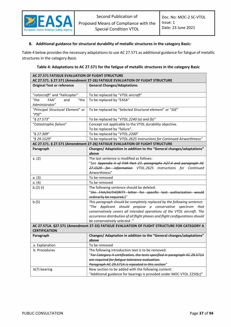
Second Publication of
Proposed Means of Compliance with the Special Condition VTOL
Doc. No: MOC-2 SC-VTOL Issue: 1 Date: 23 June 2021
PUBLIC CONSULTATION Page 37 of 94
Additional guidance for structural durability of metallic structures in the category Basic:
Table 4 below provides the necessary adaptations to use AC 27.571 as additional guidance for fatigue of metallic
structures in the category Basic
Table 4: Adaptations to AC 27.571 for the fatigue of metallic structures in the category Basic
AC 27.571 FATIGUE EVALUATION OF FLIGHT STRUCTURE AC 27.571. § 27.571 (Amendment 27-26) FATIGUE EVALUATION OF FLIGHT STRUCTURE
Original Text or reference General Changes/Adaptations
“rotorcraft” and “helicopter” To be replaced by “VTOL aircraft”
“the FAA” and “the Administrator”
To be replaced by “EASA”
“Principal Structural Element” or “PSE”
To be replaced by “Selected Structural element” or “SSE”
“§ 27.573” To be replaced by “VTOL.2240 (a) and (b)”
“Catastrophic failure” Concept not applicable to the VTOL durability objective. To be replaced by “failure”.
“§ 27.309” To be replaced by “VTOL.2200”
“§ 29.1529” To be replaced by “VTOL.2625 Instructions for Continued Airworthiness”
AC 27.571. § 27.571 (Amendment 27-26) FATIGUE EVALUATION OF FLIGHT STRUCTURE
Paragraph Changes/ Adaptation in addition to the “General changes/adaptations” above
a. (2) The last sentence is modified as follows: “See Appendix A of FAR Part 27, paragraphs A27.4 and paragraph AC 27.1529 for information VTOL.2625 Instructions for Continued Airworthiness”
a. (3) To be removed
a. (4) To be removed
b.(2) (i) The following sentence should be deleted: “(An FAA/AUTHORITY letter for specific test authorization would ordinarily be required.)“
b.(5) This paragraph should be completely replaced by the following sentence: “The Applicant should propose a conservative spectrum that conservatively covers all intended operations of the VTOL aircraft. The occurrence distribution of all flight phases and flight configurations should be conservatively selected .”
AC 27.571A. §27.571 (Amendment 27-33) FATIGUE EVALUATION OF FLIGHT STRUCTURE FOR CATEGORY A CERTIFICATION
Paragraph Changes/ Adaptation in addition to the “General changes/adaptations” above
a. Explanation To be removed
b. Procedures The following introduction text is to be removed: “For Category A certification, the tests specified in paragraph AC 29.571A are required for fatigue tolerance evaluation. Paragraph AC 29.571A is repeated in this section”
b(7) bearing New section to be added with the following content: “Additional guidance for bearings is provided under MOC VTOL 2250(c)”
Second Publication of
Proposed Means of Compliance with the Special Condition VTOL
Doc. No: MOC-2 SC-VTOL Issue: 1 Date: 23 June 2021
PUBLIC CONSULTATION Page 38 of 94
MOC VTOL.2240(d) High Energy Fragments – Particular Risk Analysis
Note: The following text is proposed to be added to MOC VTOL.2240(d) in Doc. No. MOC SC-VTOL, Issue 2
3. Structural Failure Rate (Category Basic and Enhanced)
(a) The framework outlined in section (b) “Structural Failure Rate” of MOC VTOL.2250(c) may be used to
determine:
the probability of occurrence of the first failure for Category Basic
the overall probability of subsequent failures for Category Enhanced (cascading events)
(b) The qualitative approach of section (b) “Structural Failure Rate” of MOC VTOL.2250(c) cannot be used
to justify a Structural Failure Rate lower that 10-7 per flight hour. All three aspects should be addressed,
i.e. design robustness, quality of the part and in-service continued structural robustness, however not
necessarily equally.
MOC VTOL.2240 (e) In-Service Monitoring
(a) For the purpose of VTOL.2240(e) parts having an important bearing on safety in operations are parts the
failure of which has hazardous or catastrophic effects for the aircraft.
(b) The provisions for In-Service Monitoring established in compliance with VTOL.2240(e) should include
the necessary means to verify the health and operating conditions to help ensure the continued
durability, integrity and functionality of the part. Actions arising from a finding could in the future change
the certification approach for similar components or lead to continued airworthiness action.
(c) The applicant should define an In-Service Monitoring programme which should verify the continuity of
the effectiveness of design and maintenance provisions, as well other procedures, implemented to
comply with VTOL.2240(a) and (b), VTOL.2250(a) and (c) and VTOL.2625 through the life of the type
design.
(d) The following data can be used to support the In-Service Monitoring programme:
Analysis of occurrence reports.
Analysis of unscheduled removal rates.
Results of scheduled maintenance.
Strip Reports / Analysis at overhaul.
Post-TC development and maturity tests.
Additional inspection (non-destructive and/or destructive) and testing on selected high time
or rejected components.
Feedback from lead customers.
Audits of subcontractors and suppliers of parts.
Statistical process control data of manufacturing processes that are essential to ensure the
integrity and/or functionality of the part.
Review of concessions.
Changes in utilization and operating environment.
Operator / applicant working group activities.
Health monitoring data.
Usage monitoring data.
Second Publication of
Proposed Means of Compliance with the Special Condition VTOL
Doc. No: MOC-2 SC-VTOL Issue: 1 Date: 23 June 2021
PUBLIC CONSULTATION Page 39 of 94
(e) The assessments required by the In-Service Monitoring programme should be performed at suitable
periods through the complete life of the subject component types, considering the types of operation,
environment and ageing effects expected. In addition, the applicant should consider scheduling early
evaluation opportunities to confirm the suitability of the inspection and/or other procedures developed
under VTOL.2240. Consideration should be given to adding new samples and revising the programme
when changes to the types of operation or environment occur.
(f) A plan defining the tasks and schedule of the In-Service Monitoring programme should be agreed during
certification.
(g) Regular reports stating the findings of the In-Service Monitoring programme during service should be
furnished to EASA, assessing all findings made.
MOC VTOL.2245 Aeroelasticity
(a) General. The aeroelastic stability evaluations referred to in this MOC include flutter, divergence, control
reversal and any undue loss of stability and control as a result of structural deformation. The aeroelastic
evaluation should include whirl modes associated with any lift/thrust unit or other rotating device that
contributes significant dynamic forces. Compliance with this paragraph should be shown by analyses,
tests, or some combination thereof.
(b) Aeroelastic stability envelopes. The aircraft should be designed to be free from aeroelastic instability for
all configurations and design conditions within the aeroelastic stability envelopes as follows:
For normal conditions without failures, malfunctions, or adverse conditions, all
combinations of altitudes and speeds encompassed by the VD versus altitude envelope,
enlarged at all points by an increase of 20 percent in equivalent airspeed at constant
altitude, should be considered. In addition, a proper margin of stability should exist at all
speeds up to VD and there should be no large and rapid reduction in stability as VD is
approached.
For the conditions described in (c) below, for all approved altitudes, any airspeed up to VD
should be considered.
Failure conditions of certain systems should be treated in accordance with VTOL.2205. For
these failure conditions, the speed clearances defined in MOC VTOL.2205 Figure 3 apply.
(c) Failures, malfunctions, and adverse conditions. The failures, malfunctions, and adverse conditions which
should be considered are:
For aircraft with disposable fuel: critical fuel loading conditions not shown to be extremely
improbable which may result from mismanagement of fuel
Single failures, malfunctions, or disconnections, and any combination of these that is not
extremely improbable, of elements in the primary flight control system, tab control system,
or flutter damper
Failure of any single element of the structure supporting any engine, lift/thrust unit, shaft,
or large externally mounted aerodynamic body
Failures of any single element of the lift/thrust unit structure that would affect the
aeroelastic characteristics of the aircraft
Any lift/thrust unit or rotating device capable of significant dynamic forces rotating at the
highest likely overspeed
Any damage or failure conditions, required or selected for investigation by VTOL.2240 (a)
and (b)
Second Publication of
Proposed Means of Compliance with the Special Condition VTOL
Doc. No: MOC-2 SC-VTOL Issue: 1 Date: 23 June 2021
PUBLIC CONSULTATION Page 40 of 94
Any other combination of failures, malfunctions, or adverse conditions not shown to be
extremely improbable.
(d) Flight flutter tests should be made to show that the aircraft is free from flutter, control reversal and
divergence and to show by these tests that:
Proper and adequate attempts to induce flutter have been made within the speed range up
to VD;
The vibratory response of the structure during the test indicates freedom from flutter;
A proper margin of damping exists at VD; and
There is no large and rapid reduction in damping as VD is approached.
(e) For modifications of the type design which could affect the flutter characteristics, compliance with (a)
should be shown, except that analysis alone, which is based on previously approved data, may be used
to show freedom from flutter, control reversal and divergence for all speeds up to the speed specified
for the selected method.
MOC VTOL.2250(c) No catastrophic effect from structural single failures in the Category Enhanced
Note: The following text is proposed to fully replace (b) in MOC VTOL.2250(c) in Doc. No. MOC SC-VTOL, Issue
2
(b) Structural Failure Rate
For structural elements or parts and failure modes identified in (a)(5)(ii), if a quantitative assessment is not
directly feasible, an acceptable combination of compensating provisions should be implemented that provides
sufficient confidence to achieve the safety objective and is appropriate to address the failure mode that could
result in catastrophic consequences.
It should address each of the three following aspects (1) to (3) including any relevant items from the following
non-exhaustive lists for each of them:
Design Robustness:
(i) Larger static safety margins
(ii) Thorough proven understanding of the load distribution
(iii) Natural frequencies far from the forcing frequencies
(iv) Larger fatigue (safe life) margins
(v) Damage tolerance demonstration of larger damages
(vi) Low complexity of the design and a limited number of failure modes
(vii) Design values based on a statistical A-basis (99% probability with 95% confidence) as a
minimum
Quality of the part
(i) Identification of key manufacturing parameters and processes that are strictly
controlled, the modification of which require OEM validation.
(ii) Regular material batch testing throughout the life of the element or part
(iii) Non-destructive tests (NDT) / Destructive tests (DT) of one sample from every batch
throughout the life of the element or part
(iv) Non-destructive acceptance test of every article
Second Publication of
Proposed Means of Compliance with the Special Condition VTOL
Doc. No: MOC-2 SC-VTOL Issue: 1 Date: 23 June 2021
PUBLIC CONSULTATION Page 41 of 94
(v) Process control specimens or witness coupons
(vi) Special assembly procedures or functional tests to avoid maintenance errors
(vii) Sensitivity to production process variability is low or is taken into account in the design
In-Service Continued Structural Robustness
(i) Regular non-destructive inspections (NDI)
(ii) Limited repairs permitted without TC Holder support
(iii) End of flight reports of relevant parameters, for example, vibration, loads, deflection,
temperature, acoustic emission
(iv) Active in-flight monitoring with pilot notification
(v) Continued Integrity Verification Programme (CIVP), refer to MOC VTOL.2240(e)
(vi) Health and Usage Monitoring System (HUMS), refer to MOC VTOL.2240(e)
(vii) Notification required to the TC Holder of any unusual or unexpected wear or
deterioration of parts in service
For some elements the determination of the failure rate could be more appropriately determined using other
cycles, such as flight cycles or centrifugal force cycles. A conservative spectrum should then be used to convert
the structural failure rate into probability per flight hour.
Note: The following text is proposed to be added to MOC VTOL.2250(c) in Doc. No. MOC SC-VTOL, Issue 2
(c) In the safety assessment in (a)(3) of this MOC related to bearings, as a minimum and when applicable,
the following failure modes of bearings should be considered:
rupture of one or several of the bearing constituents
partial or complete seizure of the bearing
advanced spalling of bearings races or rolling elements
advanced wear of bearing rings, rolling elements or cages
loss of bearing preload
MOC VTOL.2250(e) Doors, canopies and exits
Scope and Definitions
(a) This paragraph applies to: All doors, hatches, openable windows, access panels, covers, etc., on
the exterior of the vehicle.
(b) However, this paragraph does not apply if the door requires a specific tool to both open and close
the door.
(c) This paragraph does also not apply if the opening of the door, in any flight phase, would not cause
an event worse than Minor, as defined in VTOL.2510. The potential of persons inadvertently falling
from the vehicle, and the physiological effect on passengers, should be included in the event
classification, in addition to effects on the vehicle structure, systems, controllability etc.
(d) Latches are movable mechanical elements that, when engaged, prevent the door from opening.
(e) Latched means the latches are engaged with their structural counterparts and held in position by
the latch operating mechanism.
(f) Structural aspects of Door design, and Emergency Egress from the vehicle are out of scope of this
paragraph.
Second Publication of
Proposed Means of Compliance with the Special Condition VTOL
Doc. No: MOC-2 SC-VTOL Issue: 1 Date: 23 June 2021
PUBLIC CONSULTATION Page 42 of 94
Relevance to ASTM F3061 – 16a
(a) 13.11.1 should be applicable, and complements Section 4 below.
(b) 13.11.9 could be a means of compliance to Section 4 below, but need not be a separate point.
Occupant Retention
A seatbelt, or other occupant retention device, should not be considered an adequate alternative or mitigation
against compliance with this paragraph.
Door Latching
For all doors within the scope of this paragraph, there should be means for latching and for preventing their
opening in flight inadvertently or as a result of mechanical failure.
Direct Visual Inspection
There should be means for direct visual inspection of the latching mechanism by crew members to determine
whether the external doors (including passenger, crew, service, and cargo doors) are fully latched.
Flight Crew Indication
There should be visual means (combined with other attention-getters as appropriate) to signal to appropriate
flight crew members when doors within the scope of this paragraph are not closed and/or not fully latched.
Particular Risk Aspects
The door mechanisms should be designed such that the door will not open in case of a bird strike or other
Particular Risk effect.
MOC VTOL.2255 Protection of structure
(a) The following combination of CS-27 Amdt. 6 requirements, with their corresponding guidance material,
is accepted as a means of compliance with VTOL.2255:
SC VTOL CS -27 Amdt. 6
VTOL.2255 (a) CS 27.609 (a) Protection of Structure CS 27.607 (a) Fastener
VTOL.2255 (b) CS 27.609 (b) Protection of Structure
VTOL.2255 (c) CS 27.611 Inspection provisions
(b) For composite structures, additional guidance can be found in AMC 20-29 chapter 6.d. and 6.e and in
MOC VTOL. 2240 (a) & (b).
MOC VTOL.2260 Materials and processes
(a) The following combination of CS-27 Amdt. 6 requirements, with their corresponding guidance material,
is accepted as a means of compliance with VTOL.2260:
Second Publication of
Proposed Means of Compliance with the Special Condition VTOL
Doc. No: MOC-2 SC-VTOL Issue: 1 Date: 23 June 2021
PUBLIC CONSULTATION Page 43 of 94
SC-VTOL CS-27 Amdt. 6
VTOL.2260 (a) CS 27.603 Material CS 27.613 (c) Material strength properties and design values
VTOL.2260 (b) CS 27.605 Fabrication methods
VTOL.2260 (c) CS 27.613 (a) & (b) Material strength properties and design values
VTOL.2260 (d) CS 27.613 (a) Material strength properties and design values
VTOL.2260 (e) CS 27.603 (c) Materials
VTOL.2260 (f) CS 27.613 (e) Material strength properties and design values
VTOL.2260 (g) CS 27.613 Material strength properties and design values
(b) For composite structures, additional guidance can be found in AMC 20-29 chapter 6 and MOC VTOL.2240
(a) & (b).
(c) For additive manufacturing, additional guidance can be found in the EASA Certification Memorandum
CM-S-008.
MOC VTOL.2265 Special factors of safety
(a) The following combination of CS-27 Amdt. 6 requirements, with their corresponding guidance material,
is accepted as a means of compliance with VTOL.2265:
SC-VTOL CS-27 Amdt. 6
VTOL.2265 (a) CS 27.619(a) Special factors CS 27.621 Casting factors CS 27.785 (h) & (k)
VTOL.2265 (b) CS 27.619 Special factors CS 27.621 Casting factors CS 27.623 Bearing factors CS 27.625 Fitting factors CS 27.785 (h)&(k) Seats, berths, safety belts, and harnesses
VTOL.2265 (c) CS 27.619, applicable to limit (if any) and ultimate load conditions
(b) For items of mass which are subjected to frequent removal: In order to ensure the strength of the
components throughout the service life despite the deterioration through frequent removal, an
additional factor in accordance with 27.619(a)(2) should be applied to all loading conditions. The local
attachments for these items should be designed to withstand 1,33 times the specified loads if these
items are subject to severe wear and tear through frequent removal.
(c) For composite structure, additional guidance can be found in AMC 20-29.
(d) For additive manufacturing, additional guidance can be found in the EASA Certification Memorandum
CM-S-008.
MOC VTOL.2270(c) Emergency Landing Conditions
STRUCTURAL PROVISIONS: Ditching, Emergency Flotation and Limited Overwater Operation
VTOL aircraft will operate over different water environments, such as inland rivers and lakes, open seas and
hostile sea areas. In order to be proportionate to the nature and risk associated to these different operational
scenarios, three airworthiness categories are defined: limited overwater operations, emergency flotation and
Second Publication of
Proposed Means of Compliance with the Special Condition VTOL
Doc. No: MOC-2 SC-VTOL Issue: 1 Date: 23 June 2021
PUBLIC CONSULTATION Page 44 of 94
ditching. The air operations rules will specify the airworthiness category necessary for operations over water.
The associated design criteria for these airworthiness categories have been developed following a tiered
approach with a baseline set of conditions defined for limited overwater operations, additional criteria
necessary for emergency flotation and further considerations added for ditching operations.
If certification with ditching provisions, emergency flotation provisions or limited over water operations is
requested by the applicant, structural strength should meet the following design criteria.
If certification with emergency flotation or limited over water operations is requested, the loading conditions
apply to the buoyancy components provided to meet VTOL.2310 and VTOL.2270(c) respectively, and their
attachments to the aircraft. Buoyancy components may consist of flotation units of an emergency flotation
system (floats), watertight compartments, hull buoyancy, integrated buoyancy or a combination of these.
If certification with ditching provisions is requested, the loading conditions apply to all parts of the aircraft.
(a) Landing conditions:
The conditions considered should be those resulting from an emergency landing into calm
water.
Additionally, if certification with ditching provisions or emergency flotation provisions is
requested by the applicant, the conditions considered should also be those resulting from
an emergency landing into the most severe sea conditions for which certification is
requested by the applicant
Unless other rational landing conditions acceptable to the Agency are defined, the following
entry conditions apply: a forward ground speed not less than 15.4 m/s (30 knots), and a
vertical speed not less than 1.5 m/s (5 ft/s), in likely pitch, roll and yaw attitudes.
Total lift may be assumed to act through the centre of gravity during water entry. This lift
may not exceed two-thirds of the design maximum weight.
(b) Loads:
Aircraft with floats fixed or intended to be deployed before water contact: CS27.563(b)(1)
Amdt. 5 (or later) is accepted as a means of compliance.
Aircraft with floats intended to be deployed after initial water contact: CS27.563(b)(2) Amdt.
5 (or later) is accepted as a means of compliance.
Aircraft with watertight compartments, hull buoyancy and/or integrated buoyancy: The
loads to be considered are those resulting from the aircraft entering the water, in the
conditions defined in (a), and in accordance with flight manual procedures.
(c) Procedures:
The buoyancy components and their attachment structure should be substantiated for limit
and ultimate loads.
A review of likely damages to the structure in the vicinity of the buoyancy components
should be carried out, including consideration of splintering and sharp edges. The risk from
such damage of puncture or improper functioning of the buoyancy components during
water entry and flotation should be minimised.
Additionally if certification for ditching is requested by the applicant, any aircraft structure
the failure of which would impair flotation, capsize resistance or cabin egress should be
substantiated for limit and ultimate ditching loads, unless the effects of these failures are
Second Publication of
Proposed Means of Compliance with the Special Condition VTOL
Doc. No: MOC-2 SC-VTOL Issue: 1 Date: 23 June 2021
PUBLIC CONSULTATION Page 45 of 94
accounted for in the investigation of probable behaviour of the aircraft during water entry,
flotation, and the capsize resistance demonstrations.
CS27 Amdt. 5 (or later): AMC 27.563 provides guidance.
Limited Overwater Operations
(a) If certification for only limited overwater operations is requested by the applicant, the aircraft should
meet the design criteria defined for MOC VTOL.2310(b) Emergency Flotation, with the exception that
capsize resistance of (a)(2) and (b)(2) need not be demonstrated.
(b) The following MOC.VTOL paragraphs are also applicable:
MOC VTOL.2315 Means of egress and emergency exits
MOC VTOL.2430(a)(6) Energy retention capability in an emergency landing
MOC.VTOL.2535 Safety Equipment
MOC.VTOL.2605(d) Information related to safety equipment
MOC VTOL.2610 Instrument markings, control markings and placard
Second Publication of
Proposed Means of Compliance with the Special Condition VTOL
Doc. No: MOC-2 SC-VTOL Issue: 1 Date: 23 June 2021
PUBLIC CONSULTATION Page 46 of 94
MOC – SUBPART D – DESIGN AND CONSTRUCTION
MOC VTOL.2305 Landing Gear Systems
Scope and Definitions
This MOC applies to
(a) Wheeled landing gear, not to a skid, ski or float design
(b) Ground control of the aircraft, for the landing gear, pertains to steering by turning any of the vehicle
wheels.
The guidance assumes
(c) Normal take-off and landing is vertical. Forward-speed landings might be made for non-normal
(emergency) conditions.
(d) No significant longitudinal engine thrust on ground
(e) Steering system is restricted to low-speed taxi only
(f) Ground resonance addressed separately, at aircraft-level
Interference with Extension/Retraction
It should be shown that, in any practical circumstances, movement of the pilot’s ground control (including
movement during retraction or extension or after retraction of the landing gear) cannot interfere with the
correct retraction or extension of the landing gear, unless it can be shown that such interference cannot
create a consequence worse than Major, as defined in VTOL.2510.
Towing
If it is intended to tow the vehicle via the landing gear (either via tow-bar or via direct attachment to the
wheel(s)), the ground control system(s), towing attachment(s), and associated elements should be designed
or protected by appropriate means such that during ground manoeuvring operations effected by means
independent of the aeroplane:
(a) Damage affecting the safe operation of the ground control system is precluded, or
(b) A flight crew alert is provided, before taxi commences, if damage may have occurred.
Wheels
(a) The wheel should be approved, to ESTO C26d or equivalent
(b) The maximum static load rating of each wheel should not be less than the corresponding static ground
reaction with:
Maximum weight; and
Critical centre of gravity.
(c) The maximum limit load rating of each wheel should equal or exceed the maximum radial limit load
determined under the applicable ground load requirements of this SC.
Tyres
If the landing gear is fitted with a tyre, then it should be a tyre:
Second Publication of
Proposed Means of Compliance with the Special Condition VTOL
Doc. No: MOC-2 SC-VTOL Issue: 1 Date: 23 June 2021
PUBLIC CONSULTATION Page 47 of 94
(a) That is a proper fit on the rim of the wheel; and
(b) Of a rating that is not exceeded under:
The design maximum weight;
A load on each main wheel tyre equal to the static ground reaction corresponding to the
critical centre of gravity; and
A load on nose wheel tyres to be compared with the dynamic rating established for those
tyres equal to the reaction obtained at the nose wheel, assuming that the mass of the
vehicle acts at the most critical centre of gravity and exerts a force of 1.0 g downward and
0.25 g forward, the reactions being distributed to the nose and main wheels according to
the principles of statics with the drag reaction at the ground applied only at wheels with
brakes.
(c) Each tyre installed on a retractable landing gear system should, at the maximum size of the tyre type
expected in service, have a clearance to surrounding structure and systems that is adequate to prevent
contact between the tyre and any part of the structure or systems.
Brakes
(a) The brakes should also be adequate to counter any normal unbalanced torque when starting engines or
rotors.
(b) A park brake should be included which will hold the vehicle stopped, on a 10 degree slope, for sufficient
time to allow emergency egress.
(c) The brakes should have adequate controllability and stopping capacity to bring the vehicle safely to a
halt for any emergency running landing (including an immediate re-land). Such a running landing need
not be considered if it arises from failure combinations determined to be Extremely Improbable, as
defined in VTOL.2510.
(d) Any fatigue or endurance effect of applying the brake during high-speed taxy should be taken into
consideration.
(e) Means should be provided for each brake assembly to indicate when the heat sink is worn to the
permissible limit. The means should be reliable and readily visible.
(f) Compatibility of the wheel and brake assemblies with the vehicle and its systems should be
substantiated.
Landing Gear Warning
If a retractable landing gear is used, an aural or equally effective landing gear warning device should be
provided that functions continuously when the vehicle is in a normal landing mode and the landing gear is
not fully extended and locked. A manual shut-off capability should be provided for the warning device and
the warning system should automatically reset when the vehicle is no longer in the landing mode.
Landing Gear Position Indication
If a retractable landing gear is used, there should be a landing gear position indicator (as well as necessary
switches to actuate the indicator) or other means to inform the pilot that each gear is secured in the
extended (or retracted) position. If switches are used, they should be located and coupled to the landing
gear mechanical system in a manner that prevents an erroneous indication of either “down and locked” if
each gear is not in the fully extended position, or of “up and locked” if each landing gear is not in the fully
retracted position.
Second Publication of
Proposed Means of Compliance with the Special Condition VTOL
Doc. No: MOC-2 SC-VTOL Issue: 1 Date: 23 June 2021
PUBLIC CONSULTATION Page 48 of 94
Landing Gear Emergency Extension
If a retractable landing gear is used and other than manual power is used to operate the gear, emergency
means should be provided for extending the gear in the event of –
(a) Any reasonably probable failure in the normal retraction system; or
(b) The failure of any single source of hydraulic, electric, or equivalent energy.
MOC VTOL.2310(b) Emergency Flotation
(a) If certification for emergency flotation is requested by the applicant, the aircraft should meet the
following design criteria:
For aircraft fitted with an emergency flotation system (floats):
(i) The flotation units of the emergency flotation system and their attachments to the
aircraft should comply with the structural provisions for ditching, emergency flotation
and overwater operations of MOC VTOL.2270(c).
(ii) The aircraft should be shown to resist capsize, in the intended floating attitude, in the
sea conditions selected by the applicant. The probability of capsizing in a 5-minute
exposure to the sea conditions should be demonstrated to be less than or equal to 10.0
% with a fully serviceable emergency flotation system, with 95 % confidence. No
demonstration of capsize resistance is required for the case of the critical float
compartment having failed. Allowances should be made for probable structural damage
and leakage.
(iii) For Category Enhanced, it should be shown that the aircraft will not sink following the
functional loss of any single complete flotation unit for 15 minutes(1).
(iv) For Category Basic, it should be shown that the aircraft will not sink for 15 minutes(1)
with a fully functional emergency flotation system.
(v) An emergency flotation system that is stowed in a deflated condition during normal
flight should have a means of automatic deployment following water entry. Automatic
deployment should not rely on any manual action during flight.
For aircraft with watertight compartments, hull buoyancy and/or integrated buoyancy:
(i) The buoyancy components of the aircraft and their attachments to the aircraft should
comply with the structural provisions for ditching, emergency flotation and overwater
operations of MOC VTOL.2270(c).
(ii) The aircraft should be shown to resist capsize, in the intended floating attitude, in the
sea conditions selected by the applicant. The probability of capsizing in a 5-minute
exposure to the sea conditions should be demonstrated to be less than or equal to 10.0
% with fully functional buoyancy components, with 95 % confidence. No demonstration
of capsize resistance is required for the case of the functional loss of the critical
buoyancy component. Allowances should be made for probable structural damage and
leakage.
(iii) For Category Enhanced, it should be shown that the aircraft will not sink following the
functional loss of any single buoyancy component for 15 minutes(1).
(iv) For Category Basic, it should be shown that the aircraft will not sink for 15 minutes(1)
with fully functional buoyancy components.
Second Publication of
Proposed Means of Compliance with the Special Condition VTOL
Doc. No: MOC-2 SC-VTOL Issue: 1 Date: 23 June 2021
PUBLIC CONSULTATION Page 49 of 94
Note (1): 15 minutes is consistent with MOC VTOL.2325(a)(4) Fire Protection – Energy storage crash
resistance.
(b) CS27 Amdt. 5 (or later): AMC 27.802 and ‘AMC to CS27.801(e) and 27.802(c)’ provide additional
guidance.
(c) If certification with emergency flotation provisions is requested by the applicant, the flight manual
should contain the substantiated sea conditions and any associated information relating to the
certification obtained with emergency flotation provisions.
(d) The following MOCs are also applicable:
MOC VTOL.2315 Means of egress and emergency exits
MOC VTOL.2430(a)(6) Energy retention capability in an emergency landing
MOC.VTOL.2535 Safety Equipment
MOC.VTOL.2605(d) Information related to safety equipment
MOC VTOL.2610 Instrument markings, control markings and placard
MOC VTOL.2310(c) Ditching
(a) If certification with ditching provisions is requested by the applicant, the aircraft should meet the
following design criteria:
The design criteria defined for MOC VTOL.2310(b) Emergency Flotation
The aircraft should comply with the structural provisions for ditching, emergency flotation
and overwater operations of MOC VTOL.2270
Each practicable design measure, compatible with the general characteristics of the aircraft,
should be taken to minimise the probability that when ditching, the behaviour of the aircraft
would cause immediate injury to the occupants or would make it impossible for them to
escape.
The probable behaviour of the aircraft during ditching water entry should be shown to
exhibit no unsafe characteristics.
For aircraft fitted with an emergency flotation system:
(i) The aircraft should be shown to resist capsize, in the intended floating attitude, in the
sea conditions selected by the applicant. The probability of capsizing in a 5-minute
exposure to the sea conditions should be substantiated to be less than or equal to 3.0
% with a fully serviceable emergency flotation system and 30.0 % with the critical float
compartment failed, with 95 % confidence.
(ii) Allowances should be made for probable structural damage and leakage.
(iii) An emergency flotation system that is stowed in a deflated condition during normal
flight should be designed such that the effects of a water impact (i.e. crash) on the
emergency flotation system are minimized.
For aircraft with watertight compartments, hull buoyancy and/or integrated buoyancy:
(i) The aircraft should be shown to resist capsize, in the intended floating attitude, in the
sea conditions selected by the applicant. The probability of capsizing in a 5-minute
exposure to the sea conditions should be substantiated to be less than or equal to 3.0
% with fully functional buoyancy components, and 30.0 % with the functional loss of the
critical buoyancy component, with 95 % confidence.
Second Publication of
Proposed Means of Compliance with the Special Condition VTOL
Doc. No: MOC-2 SC-VTOL Issue: 1 Date: 23 June 2021
PUBLIC CONSULTATION Page 50 of 94
(ii) Allowances should be made for probable structural damage and leakage.
(iii) The buoyancy components should be designed such that the effects of a water impact
(i.e. crash) on the buoyancy components are minimised.
Unless the effects of the collapse of external doors and windows are accounted for in the
investigation of the probable behaviour of the aircraft during ditching and for the capsize
resistance demonstration, the external doors and windows should be designed to withstand
the probable maximum local pressures.
Additionally, for Category Enhanced: The aircraft design should incorporate appropriate
post-capsize survivability features to enable all passenger cabin occupants to safely egress
the aircraft, taking into account the human breath hold capability.
(i) One method of meeting this post-capsize survivability provision is to create stable
floating attitudes which will create an air pocket in the passenger cabin. Passengers can
utilise the air in the pocket for continued survival during the time needed for all to make
their escape.
(ii) The size and shape of the air pocket should be sufficient to accommodate all passengers.
A minimum volume per passenger, in the form of an elliptical column of 70 cm x 50 cm
(27 in. x 19 in.) and height of 30 cm (11 in.) relative to the static waterline should be
established and demonstrated as fitting into the air pocket, including with the critical
float compartment or buoyancy component failed.
(iii) The air pocket should be accessible and immediately available without passengers
needing to cross seat backs
(iv) Emergency breathing systems (EBSs) that are capable of being quickly deployed
underwater do exist. This type of personal protective equipment (PPE) may provide a
limited level of mitigation for the issues related to human breath hold capability, but it
should not be considered alone as being sufficient to meet the post-capsize survivability
provisions.
(b) CS27 Amdt. 5 (or later): AMC 27.801 and AMC to CS27.801(e) and 27.802(c) provide additional guidance.
(c) If certification with ditching provisions is requested by the applicant, the flight manual should contain
the substantiated sea conditions and any associated information relating to the certification obtained
with ditching provisions.
(d) The following MOCs are also applicable:
MOC VTOL.2315 Means of egress and emergency exits
MOC VTOL.2430(a)(6) Energy retention capability in an emergency landing
MOC.VTOL.2535 Safety Equipment
MOC.VTOL.2605(d) Information related to safety equipment
MOC VTOL.2610 Instrument markings, control markings and placard
MOC VTOL.2315(a) Means of egress and emergency exits
Means of egress and emergency exits for Ditching, Emergency Flotation and Limited Overwater
Operations
(a) If certification with emergency flotation provisions or limited overwater operations is requested by the
applicant, the aircraft should meet the following design criteria:
Second Publication of
Proposed Means of Compliance with the Special Condition VTOL
Doc. No: MOC-2 SC-VTOL Issue: 1 Date: 23 June 2021
PUBLIC CONSULTATION Page 51 of 94
There should be an emergency exit accessible to each passenger on each side of the cabin
with the aircraft in any stable floating attitude.
Each emergency exit should be reasonably protected from becoming jammed as a result of
fuselage deformation.
In addition, for flight crew underwater exits: If flight crew emergency exits are submerged
in any stable floating position, these exits should meet the following design criteria:
(i) Each exit should be shown by test, demonstration, or analysis to be accessible and
operable underwater. Evaluations should consider ranges of size and strength found in
the 5th percentile female to the 95th percentile male.
(ii) Each operational device (pull tab(s), operating handle, ‘push here’ decal, etc.) should be
marked with black and yellow stripes.
(iii) The exit should be marked so to be readily located and operated even in darkness, and
these markings should remain visible if the cockpit is submerged.
In addition, for passenger underwater exits: If passenger emergency exits are submerged
in any stable floating position, these exits should meet the following design criteria:
(i) Each exit should be shown by test, demonstration, or analysis to be accessible and
operable underwater to give each occupant every reasonable chance of escaping.
Evaluations should consider ranges of size and strength found in the 5th percentile
female to the 95th percentile male.
(ii) Each operational marking (pull tab(s), operating handle, ‘push here’ decal, etc.) should
be marked with black and yellow stripes.
(iii) The exit should be provided with a suitable handhold, or handholds adjacently located
inside the cabin, to assist occupants in locating and operating the exit, as well as in
egressing through the emergency exit.
(iv) The exit should be marked so to be readily located and operated even in darkness, and
these markings should remain visible if the cabin is submerged.
Additionally, for aircraft fitted with an emergency flotation system (floats):
(i) Each emergency exit, including underwater exits, should be shown by test,
demonstration, or analysis to open without interference from flotation devices,
whether stowed or deployed, and with the aircraft in any stable floating attitude.
(b) CS27 Amdt. 5 (or later): AMC 27.805(c) and AMC 27.807(d) provide additional guidance for certification
with emergency flotation provisions or limited overwater operations
(c) If certification with ditching provisions is requested by the applicant, the aircraft should meet the
following design criteria:
Each emergency exit, including underwater exits, should be reasonably protected from
becoming jammed as a result of fuselage deformation.
Any non-jettisonable doors intended for use after a ditching should have means to enable
them to be secured in the open position and remain secure for emergency egress in all sea
conditions for which ditching capability is requested by the applicant
For Category Enhanced the following is also applicable:
(i) Ditching emergency exits should be provided such that following a ditching, in all sea
conditions for which ditching capability is requested by the applicant and in the
Second Publication of
Proposed Means of Compliance with the Special Condition VTOL
Doc. No: MOC-2 SC-VTOL Issue: 1 Date: 23 June 2021
PUBLIC CONSULTATION Page 52 of 94
intended floating attitude, passengers are able to evacuate the aircraft and step directly
into any of the required life raft
(ii) It should be possible for each passenger to egress the aircraft via the nearest
underwater emergency exit, when capsized, with any door in the open and secured
position;
(iii) Means should be provided to assist cross-cabin escape when capsized
(d) In addition, for flight crew underwater exits: Flight crew emergency exits should meet the following
design criteria:
Each exit should be shown by test, demonstration, or analysis to provide for rapid escape in
any stable floating attitude. Evaluations should consider ranges of size and strength found
in the 5th percentile female to the 95th percentile male.
The average load required to operate the exit release mechanism and open the exit should
not exceed 222N (50 lbf), and the maximum individual load of a test series should not
exceed 245N (55 lbf).
Each operational device (pull tab(s), operating handle, ‘push here’ decal, etc.) should be
marked with black and yellow stripes and should be shown to be accessible for the range of
required flight crew heights and for both the case of an un-deformed seat and a seat with
any deformation resulting from the test conditions required by VTOL.2270(b)(1)
For Category Enhanced: each exit, its means of access and its means of opening, should be
provided with highly conspicuous illuminated markings that illuminate automatically and
are designed to remain visible in any stable floating attitude and the cockpit flooded.
For Category Basic: The exit should be marked so to be readily located and operated even
in darkness, and these markings should remain visible if the cockpit is submerged
(e) In addition, for passenger underwater exits: Underwater emergency exits should be provided in
accordance with the following requirements and should be proven by test, demonstration, or analysis
to provide for rapid escape with the aircraft in any stable floating attitude:
One underwater emergency exit, providing an unobstructed opening that will admit a 0.48
m by 0.66 m (19 inch by 26 inch) ellipse, should be installed in each side of the aircraft for
each unit (or part of a unit) of four passenger seats. However, the seat-to-exit ratio may be
increased for underwater emergency exits large enough to permit the simultaneous egress
of two passengers side by side.
Passenger seats should be located in relation to the underwater emergency exits in a way
to best facilitate escape with the aircraft capsized and the cabin flooded
Underwater emergency exits, including their means of operation, markings, lighting and
accessibility, should be designed for use in a flooded and capsized cabin. Evaluations should
consider ranges of size and strength found in the 5th percentile female to the 95th
percentile male.
The average load required to operate the exit release mechanism and open the exit should
not exceed 222N (50 lbf), and the maximum individual load of a test series should not
exceed 245N (55 lbf).
Each operational marking (pull tab(s), operating handle, ‘push here’ decal, etc.) should be
marked with black and yellow stripes.
Second Publication of
Proposed Means of Compliance with the Special Condition VTOL
Doc. No: MOC-2 SC-VTOL Issue: 1 Date: 23 June 2021
PUBLIC CONSULTATION Page 53 of 94
The exit should be provided with a suitable handhold, or handholds adjacently located
inside the cabin, to assist occupants in locating and operating the exit, as well as in egressing
through the emergency exit.
For Category Enhanced: each exit, its means of access and its means of opening, should be
provided with highly conspicuous illuminated markings that illuminate automatically and
are designed to remain visible in any stable floating attitude and the cabin flooded.
For Category Basic: The exit should be marked so to be readily located and operated even
in darkness, and these markings should remain visible if the cockpit is submerged
(f) Additionally, for aircraft fitted with an emergency flotation system:
Each emergency exit, including underwater exits, should be shown by test, demonstration,
or analysis to open without interference from flotation devices, whether stowed or
deployed, and with the aircraft in any stable floating attitude.
(g) CS27 Amdt. 5 (or later): AMC 27.783, AMC 27.805(c), AMC 27.807(d) and AMC 29.803(c) provide
additional guidance.
MOC VTOL.2320(a)(1) Clear communication between flight crew and passengers
(a) CS 23.771(b) and CS23.791 are accepted as a means of compliance.
MOC VTOL.2320(a)(3) Occupant protection from breakage of windshields, windows, and canopies
(a) CS 27.775 Amdt. 5 (or later) is accepted as a means of compliance.
(b) In addition, for Category Enhanced and Category Basic with a maximum seating configuration of 7 or
more, the windshield should be evaluated for a single bird strike in accordance with VTOL.2250(f).
MOC VTOL.2325(b)(1) and (b)(2) Fire Protection: Minimisation of Fire Propagation
Note: The following text is proposed to be added to MOC VTOL.2325 (b)(1) and (b)(2) in Doc. No. MOC SC-
VTOL, Issue 2:
3. Designated fire zones (Category Basic and Enhanced)
(a) Detection Systems:
It is accepted that adequate fire or smoke awareness for the designated fire zones is provided by the
installation of detection systems that follow Section 3(h) in MOC VTOL.2330.
(b) Extinguishing Systems:
Following CS requirements are accepted as means to comply with VTOL.2325(b)(1) regarding adequate
extinguishing means in the designated fire zones:
CS 29.1195 Amdt. 6 “Fire extinguishing systems”
CS 29.1197 Amdt. 6 “Fire extinguishing agents”
CS 29.1199 Amdt. 6 “Extinguishing agent containers”
CS 29.1201 Amdt. 6“Fire extinguishing system materials”
Second Publication of
Proposed Means of Compliance with the Special Condition VTOL
Doc. No: MOC-2 SC-VTOL Issue: 1 Date: 23 June 2021
PUBLIC CONSULTATION Page 54 of 94
MOC VTOL.2330 Fire Protection in designated fire zones
Definitions and Terminology
For the purpose of this MOC, the following definitions are provided:
(a) Considered zones for VTOL are:
Fire withstanding zone
Explosive fire zone
(b) Electrical Energy Storage System (EESS):
Battery necessary for the propulsion of VTOL aircraft.
(c) Fire withstanding capability (Electrical lift/thrust unit fire):
The required fire withstanding capability is dependent on the electrical lift/thrust unit flame
characterisation. This characterisation should be performed using the design, the materials characteristics,
power, etc. The minimum required time duration of this capability is dependent on the VTOL aircraft
Category and is determined from the moment it would be subject to the fire effect.
(d) Fire withstanding zone (Electrical lift/thrust unit fire):
Is a volume surrounding one or several electrical thrust/lift units that could be open or closed and able to
withstand the effect of a flame and/or sparks, arcing, heat, hot parts ejection.
(e) Explosive fire capability (Electrical Energy Storage System fire):
The required explosive fire capability is dependent on the battery flame characterisation. This
characterisation of fire temperature and pressure should be performed using the design of the battery (i.e.
chemistry, cells dimensions, cells design, etc.). The minimum required time duration of the explosive fire
capability is dependent on the VTOL aircraft category and determined from the moment it would be subject
to the explosive fire effect.
(f) Explosive fire zone (Electrical Energy System Storage fire):
Is a volume surrounding an EESS with or without an electrical thrust/lift unit that could be open or closed
and able to withstand the effect of a flame and/or sparks, heat, pressure and hot parts ejection.
(g) Minimum Fire Capability:
With respect to materials, components and equipment, means the capability to withstand the application
of heat by a flame, as defined for ‘Fire withstanding / Explosive fire’, including an ensuing:
continued safe flight and landing, for Category enhanced VTOL aircraft, or
controlled emergency landing, for Category Basic VTOL aircraft.
Applicability and Scope
MOC VTOL.2330 will be developed in an incremental approach according to the following steps:
(a) Step 1: Air cooled engine with rechargeable batteries as electrical energy storage system not liquid
cooled,
(b) Step 2: Air cooled engine with liquid cooled battery (oil, glycol water, etc…),
Second Publication of
Proposed Means of Compliance with the Special Condition VTOL
Doc. No: MOC-2 SC-VTOL Issue: 1 Date: 23 June 2021
PUBLIC CONSULTATION Page 55 of 94
(c) Step 3: Other energy storage technologies (e.g. fuel cells, capacitors) or hybrid propulsion. For instance:
liquid cooled engine with liquid cooled battery.
The MOC at hand provides guidance and methods for addressing the fire protection of the installation of electric
propulsion systems in VTOL using rechargeable batteries as electrical energy storage system not liquid cooled
[step 1]. For different energy storage technologies (e.g. fuel cells, capacitors) or hybrid propulsion systems this
MOC is not yet applicable and will be completed [steps 2 and 3].
The certification of electric engines and propellers is not part of this MOC.
This MOC does not cover or replace applicable regulations for qualification, handling, storage, transport and
disposal of batteries.
It is applicable to VTOL Aircraft in Category Basic and Enhanced.
Protection against the effects of fire
(a) Fire protection of flight controls, engine mounts, and other flight structure: Flight controls, engine
mounts and other flight structure located in the Fire Withstanding Zone or Explosive Fire Zone or in
adjacent areas subject to the effects of fire should be constructed of materials or shielded to withstand
the effects of fire, so that they can perform their essential function during a time that covers at least the
detection of the fire at the most adverse operating condition and an ensuing:
continued safe flight and landing, for Category Enhanced VTOL aircraft, or.
controlled emergency landing, for Category Basic VTOL aircraft.
(b) Areas adjacent to fire withstanding zone or explosive fire zone: Components, electrical lines and fittings,
located in area adjacent to Fire Withstanding Zone or an Explosive Fire Zone should be constructed of
such materials and located such that they will not suffer sufficient damage to endanger the VTOL aircraft
if a portion of the lift/thrust unit or EESS is subject to a characterised flame for a time covering at least
the detection of the fire at the most adverse operating condition and an ensuing:
continued safe flight and landing, for Category Enhanced VTOL aircraft, or
controlled emergency landing, for Category Basic VTOL aircraft.
(c) Drainage and ventilation of Fire Withstanding Zone and Explosive Fire Zone
There should be a complete drainage of each part of each Fire Withstanding Zone or
Explosive Fire Zone if any presence of fluids can occur. The drainage means should be:
(i) Effective under conditions expected to prevail when drainage is needed; and
(ii) Arranged so that no discharged fluids or corrosive gases, smoke, soot, particulate will
cause an additional hazard.
Each Fire Withstanding Zone or Explosive Fire Zone should be ventilated to prevent the
accumulation of emitting corrosive gases, smoke, soot, particulate.
No ventilation opening may be where it would allow the entry of fluids, of emitting corrosive
gases, smoke, soot, particulate or flame from other zones.
The ventilation means should be:
(i) effective under conditions expected to prevail when ventilation is needed;
Second Publication of
Proposed Means of Compliance with the Special Condition VTOL
Doc. No: MOC-2 SC-VTOL Issue: 1 Date: 23 June 2021
PUBLIC CONSULTATION Page 56 of 94
(ii) arranged so that no discharge of emitted corrosive gases, smoke, soot, particulate or
flame will cause an additional fire hazard or impinge occupants or persons on the
ground (refer to Hazard Areas, as defined in paragraph (d) of MOC VTOL.2400(c)(3)).
(d) Disconnect mechanism
For each EESS there should be a means to disconnect and isolate the battery from the main
electrical circuit.
For each lift/thrust unit there should be a means to disconnect and isolate the engine from
the main electrical circuit.
Quick automatic disconnection limiting the fire temperature and heat flux to an acceptable
level allowing a:
(i) continued safe flight and landing for Category Enhanced VTOL aircraft
(ii) controlled emergency landing for Category Basic VTOL aircraft.
(e) Fire withstanding wall
Each lift/thrust unit, should be isolated by a Fire Withstanding Wall, shroud, or equivalent
means, from personnel compartments, structures, controls, and any other parts that are:
(i) Affected by the lift/thrust unit fire
(ii) Not protected under “Fire protection of flight controls, engine mounts and other flight
structure” of this MOC and,
(iii) Essential to control the flight and landing at the most adverse operating condition and
an ensuing:
a. continued safe flight and landing, for Category Enhanced VTOL aircraft, or
b. controlled emergency landing, for Category Basic VTOL aircraft.
Each opening in the Fire Withstanding Wall or shroud should be sealed with close-fitting fire
withstanding grommets, bushings, or firewall fittings.
Each Fire Withstanding Wall and shroud should be:
(i) constructed so that no hazardous quantity of fumes, arc or spark, fluids or liquid metal
or flame can pass from any lift/thrust unit compartment to other parts of the VTOL
aircraft, and
(ii) protected against corrosion and capable to sustain a fire, spark or arc so that the
essential elements it protects can perform their essential function
The conditions in (e) (3)(i) and (ii) should be fulfilled for a duration of time covering at least
the detection of the fire at the most adverse operating condition and an ensuing:
(i) continued safe flight and landing, for Category Enhanced VTOL aircraft, or
(ii) controlled emergency landing, for Category Basic VTOL aircraft.
In meeting this paragraph, account should be taken of the probable path of a fire as affected
by the airflow in normal flight and vertical take-off and landing.
(f) Explosive firewall
Each EESS should be isolated by an Explosive firewall, shroud, or equivalent means, from
personnel compartments, structures, controls, and any other parts that are:
Second Publication of
Proposed Means of Compliance with the Special Condition VTOL
Doc. No: MOC-2 SC-VTOL Issue: 1 Date: 23 June 2021
PUBLIC CONSULTATION Page 57 of 94
(i) Not protected under “Fire protection of flight controls, engine mounts and other flight
structure” of this MOC and,
(ii) Essential to control the flight and landing at the most adverse operating condition and
an ensuing:
a. continued safe flight and landing, for Category Enhanced VTOL aircraft, or
b. controlled emergency landing, for Category Basic VTOL aircraft.
Each opening in the Explosive Firewall should be sealed with close-fitting as grommets,
bushings, or fittings able to withstand the heat and pressure created by a thermal runaway
of battery.
Each Explosive Firewall and shroud should be:
(i) constructed so that no hazardous quantity of fluid, corrosive gases, smoke, soot,
particulate, liquid metal or flame can pass from any EESS compartment to other parts
of the VTOL aircraft, and
(ii) protected against corrosion and resistant to the heat and pressure created by a thermal
runaway of battery capable to sustain a fire, spark or arc so that the essential elements
it protects can perform their essential function.
The conditions in (f) (3)(i) and (ii) should be fulfilled for a duration of time covering at least
the detection of the fire at the most adverse operating condition and an ensuing:
(i) continued safe flight and landing, for Category Enhanced VTOL aircraft, or
(ii) controlled emergency landing, for Category Basic VTOL aircraft.
In meeting this paragraph, account should be taken of the probable path of a fire as affected
by the airflow in normal flight and vertical take-off and landing.
(g) Following CS requirements provide means that can be used to comply with VTOL.2330(a):
CS 27.1194 Amdt. 6 “Other surfaces”
CS 29.1195 Amdt. 6 “Fire extinguishing systems”
CS 29.1197 Amdt. 6 “Fire extinguishing agents”
CS 29.1199 Amdt. 6 “Extinguishing agent containers”
CS 29.1201 Amdt. 6“Fire extinguishing system materials”
(h) Detection systems
Detection systems include but are not limited to: quick-acting fire, gases, over temperature
/ under voltage / overvoltage/overpressure.
For each EESS and lift/thrust unit there should be approved, quick-acting detectors in fire
zones in numbers and locations ensuring prompt detection of fire in those zones
Each detector should be constructed and installed to withstand any loads to which it would
be subjected in operation.
No detector should be affected by any oil, water, other fluids, or fumes, soot and corrosive
gas that might be present.
There should be means to allow crew members to check the functioning of each detector
system electrical circuit.
The wiring and other components of each detector system in an electrical energy storage
system compartment should have at least Minimum Fire Capability.
Second Publication of
Proposed Means of Compliance with the Special Condition VTOL
Doc. No: MOC-2 SC-VTOL Issue: 1 Date: 23 June 2021
PUBLIC CONSULTATION Page 58 of 94
No detector system component for any fire zone should pass through another fire zone,
unless–
(i) It is protected against the possibility of false warnings resulting from fires in zones
through which it passes; or
(ii) The zones involved are simultaneously protected by the same detector and
extinguishing systems.
Second Publication of
Proposed Means of Compliance with the Special Condition VTOL
Doc. No: MOC-2 SC-VTOL Issue: 1 Date: 23 June 2021
PUBLIC CONSULTATION Page 59 of 94
MOC - SUBPART E – LIFT/THRUST SYSTEM INSTALLATION
MOC VTOL.2400(c)(3) Lift/thrust system installation – likely hazards in operation
The likely hazards in operation, including hazards to ground personnel, that the applicant must account for
should include:
(a) Risk of inadvertent electric motor start (if applicable):
The aircraft controls should prevent inadvertent sudden motor operation when not commanded by the
pilot, in particular during the aircraft supply power-on.
(b) Rotor/propeller disk conspicuity during landing, take-off and ground operations (if applicable):
CS 27.1565 Amdt. 6 is accepted as a means of compliance for rotors, propellers and other rotating parts that
could hit and injure ground personnel. Considerations for night conditions should also be included if night
operations are authorised.
(c) Downwash effect on third parties:
The downwash of the aircraft should be characterised and reported to allow safe operation and
minimisation of hazards to ground personnel.
The following method can be followed to test and report aircraft downwash:
Preliminary assessment:
The applicant should assess whether the test as described in this appendix can be conducted
safely for his aircraft.
Test:
While the aircraft is in a low hover, the radial component of the downwash (outwash) is
measured around the aircraft on a circle of diameter 2 D.
Reporting:
The maximum measured speed is reported in km/h to the nearest multiple of 5, as well as
the measurement standard (here “§(c) in MOC VTOL.2400(c)(3)”), in the performance
section of the aircraft flight manual.
If the downwash temperature on the 2 D-diameter circle is more than 10°C above ambient
temperature, this should also be characterised and reported.
Note: ‘D’ is reported as part of MOC VTOL.2115.
Test specification:
Parameter Description Value Tolerance
Conditions density altitude ≤ 2000 ft - ambient wind, throughout each test run, measured 2 m
above the ground within 200 m of the circle centre. Location should be representative of the test condition.
≤ 3 kt -
no precipitations - - Surface Smooth pavement, e.g. concrete or asphalt, surrounded by clear area, e.g. grass (Figure 1) diameter pavement ≥ 3 D - diameter clear area ≥ 6 D naturally occurring height discontinuity on pavement
(excluding measuring equipment and operator, e.g. joint between concrete slabs)
≤ 2 cm -
Second Publication of
Proposed Means of Compliance with the Special Condition VTOL
Doc. No: MOC-2 SC-VTOL Issue: 1 Date: 23 June 2021
PUBLIC CONSULTATION Page 60 of 94
Parameter Description Value Tolerance naturally occurring height discontinuity on clear area
(e.g. grass) ≤ 20 cm -
pavement level (locally and overall) 0° ± 2° clear area level (locally and overall) 0° ± 5° Aircraft position
Hovering in a normal take-off and landing configuration, holding height or a power datum. Up to 8 poles can be used to assist in visually positioning the aircraft.
height (from the bottom of the landing gear) 1 m (2)
heading - (2) lateral and longitudinal position - (2) mass MTOM -0.1% diameter of poles ≤ 3 cm - Measurement positions
Measuring at discrete locations on the 2 D circle(1) - option 1: While the aircraft is maintained on a fixed heading, successive
measurements are taken around the 2 D circle (Figure 2) - option 2: The aircraft is yawed facing successive aiming points while measurements
are taken at 4 fixed cardinal positions on the 2 D circle to compensate for residual ambient wind (Figure 3). The measurement intervals at the 4 positions should be synchronised (within ± 1 sec).
distance between successive measurement positions (option 1) or aiming points (option 2)
≤ 2 m -
heights (Figure 4)
0.5 m and 1.5 m
± 5 cm
lateral and longitudinal position - ± 10 cm measure in the radial direction - ± 5° measure the horizontal wind component - ± 5° measure the maximum over time (for each measurement) ≥ 10 s - Measuring support
An operator and up to 4 poles, or a tripod, can be used to assist in positioning the measuring equipment. The operator and poles should not be located directly in front or behind the measuring equipment.
diameter of poles or tripod legs ≤ 3 cm - position of operator laterally of measuring equipment ≥ 2 m - Measuring equipment
For example vane anemometer
accuracy wind speed ≤ ± 4.5 km/h - accuracy temperature (if applicable) ≤ ± 3°C - resolution wind speed ≤ 1 km/h - wind speed reporting interval ≤ 3 sec (3) -
(1) The 2 D circle should be centred on the centre of the smallest enclosing circle (refer to MOC VTOL.2115 Section
7). (2) The accuracy of the hover should meet the “Desired” MHQRM for a 1 m-height precision hover (ref. MOC
VTOL.2135) (3) or “maximum” reporting function
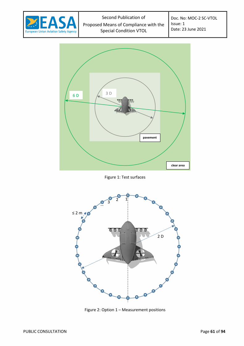
Second Publication of
Proposed Means of Compliance with the Special Condition VTOL
Doc. No: MOC-2 SC-VTOL Issue: 1 Date: 23 June 2021
PUBLIC CONSULTATION Page 61 of 94
Figure 1: Test surfaces
Figure 2: Option 1 – Measurement positions
3 D 6 D
pavement
clear area
≤ 2 m
2 D
1 2 3
…
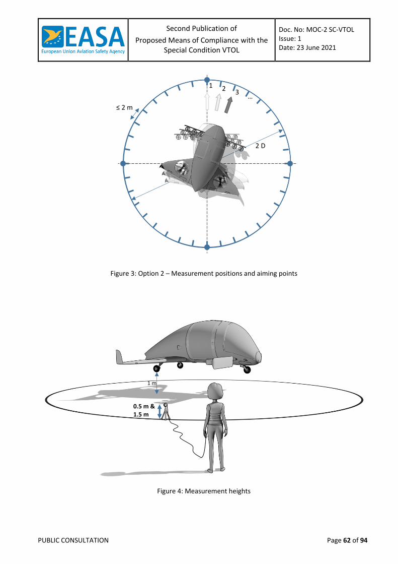
Second Publication of
Proposed Means of Compliance with the Special Condition VTOL
Doc. No: MOC-2 SC-VTOL Issue: 1 Date: 23 June 2021
PUBLIC CONSULTATION Page 62 of 94
Figure 3: Option 2 – Measurement positions and aiming points
Figure 4: Measurement heights
≤ 2 m
2 D
1 2 3 …
1 m
0.5 m & 1.5 m
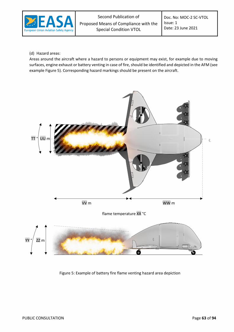
Second Publication of
Proposed Means of Compliance with the Special Condition VTOL
Doc. No: MOC-2 SC-VTOL Issue: 1 Date: 23 June 2021
PUBLIC CONSULTATION Page 63 of 94
(d) Hazard areas:
Areas around the aircraft where a hazard to persons or equipment may exist, for example due to moving
surfaces, engine exhaust or battery venting in case of fire, should be identified and depicted in the AFM (see
example Figure 5). Corresponding hazard markings should be present on the aircraft.
Figure 5: Example of battery fire flame venting hazard area depiction
UU m TT °
VV m WW m
flame temperature XX °C
ZZ m YY °
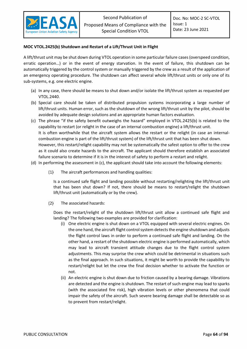
Second Publication of
Proposed Means of Compliance with the Special Condition VTOL
Doc. No: MOC-2 SC-VTOL Issue: 1 Date: 23 June 2021
PUBLIC CONSULTATION Page 64 of 94
MOC VTOL.2425(b) Shutdown and Restart of a Lift/Thrust Unit in Flight
A lift/thrust unit may be shut down during VTOL operation in some particular failure cases (overspeed condition,
erratic operation…) or in the event of energy starvation. In the event of failure, this shutdown can be
automatically triggered by the control system or manually triggered by the crew as a result of the application of
an emergency operating procedure. The shutdown can affect several whole lift/thrust units or only one of its
sub-systems, e.g. one electric engine.
(a) In any case, there should be means to shut down and/or isolate the lift/thrust system as requested per
VTOL.2440.
(b) Special care should be taken of distributed propulsion systems incorporating a large number of
lift/thrust units. Human error, such as the shutdown of the wrong lift/thrust unit by the pilot, should be
avoided by adequate design solutions and an appropriate human factors evaluation.
(c) The phrase “if the safety benefit outweighs the hazard” employed in VTOL.2425(b) is related to the
capability to restart (or relight in the case of an internal combustion engine) a lift/thrust unit.
It is often worthwhile that the aircraft system allows the restart or the relight (in case an internal-
combustion engine is part of the lift/thrust system) of the lift/thrust unit that has been shut down.
However, this restart/relight capability may not be systematically the safest option to offer to the crew
as it could also create hazards to the aircraft. The applicant should therefore establish an associated
failure scenario to determine if it is in the interest of safety to perform a restart and relight.
(d) In performing the assessment in (c), the applicant should take into account the following elements:
The aircraft performances and handling qualities:
Is a continued safe flight and landing possible without restarting/relighting the lift/thrust unit that has been shut down? If not, there should be means to restart/relight the shutdown lift/thrust unit (automatically or by the crew).
The associated hazards:
Does the restart/relight of the shutdown lift/thrust unit allow a continued safe flight and landing? The following two examples are provided for clarification:
(i) One electric engine is shut down on a VTOL equipped with several electric engines. On
the one hand, the aircraft flight control system detects the engine shutdown and adjusts
the flight control laws in order to perform a continued safe flight and landing. On the
other hand, a restart of the shutdown electric engine is performed automatically, which
may lead to aircraft transient attitude changes due to the flight control system
adjustments. This may surprise the crew which could be detrimental in situations such
as the final approach. In such situations, it might be worth to provide the capability to
restart/relight but let the crew the final decision whether to activate the function or
not.
(ii) An electric engine is shut down due to friction caused by a bearing damage. Vibrations
are detected and the engine is shutdown. The restart of such engine may lead to sparks
(with the associated fire risk), high vibration levels or other phenomena that could
impair the safety of the aircraft. Such severe bearing damage shall be detectable so as
to prevent from restart/relight.
Second Publication of
Proposed Means of Compliance with the Special Condition VTOL
Doc. No: MOC-2 SC-VTOL Issue: 1 Date: 23 June 2021
PUBLIC CONSULTATION Page 65 of 94
Human factors
VTOL concepts are often designed around a significant number of lift/thrust units. The applicant should assess if manual operating procedures to restart or relight a shutdown lift/thrust unit are compatible with the workload of the crew or if the procedures should be automated, and what are the possibilities of erroneous manipulation of the lift/thrust unit controls during a restart/relight performed by the crew, as well as possible ways of mitigating them by design.
MOC VTOL.2430(a)(3) and (a)(4) Accessible energy in electrical energy storage systems
(a) Eurocae ED-289 “Guidance on the determination of accessible energy in battery systems for eVTOL
applications” is accepted as a means to determine the adequate margins of an electrical energy storage
system required by VTOL.2430(a)(3).
(b) Eurocae ED-289 “Guidance on the determination of accessible energy in battery systems for eVTOL
applications” is accepted as a means to define the reliability of the relevant information of an electrical
energy storage system to be provided to the flight crew as required by VTOL.2430(a)(4) and established
in VTOL.2445(g).
MOC VTOL.2435(f) Prevention of likely foreign object damage to the lift/thrust unit
(a) The demonstration of compliance with VTOL.2435(f) should consider any foreign object of a nature such
that it could impair the proper functioning of the lift/thrust system.
(b) It should be substantiated that the strike and ingestion effects of foreign objects such as plastic bags,
papers, cleaning cloths, hand tools, rivets, bolts and screws are not hazardous to the aircraft.
(c) Design precautions should be taken to avoid the clogging of cooling holes by foreign object damage.
MOC VTOL.2435(g) Flight crew awareness of the lift/thrust unit configuration
This MOC is applicable in case that several configurations of the lift/thrust system are part of the VTOL type design definition. It is a common practice in the rotorcraft industry that turbines are equipped with different kinds of air intakes depending on the mission. The crew must be aware of the associated configuration in order to apply the proper procedures and to adequately calculate the performances.
(a) The term “configuration” of the lift/thrust system mentioned in VTOL.2435 (g) refers only to “physical”
configuration. It does not consider the different aerodynamic conditions that a lift/thrust system may
be subject to within the certified envelope. For example, a lift/thrust unit mounted on a titling element
is considered as a single configuration even though the aerodynamic conditions in which the lift/thrust
unit operate depend on the tilting angle.
(b) The intent of VTOL.2435(g) is therefore to provide the flight crew through the relevant VTOL aircraft
systems, with the necessary information concerning any lift/thrust configuration that has an impact on:
the lift/thrust performances
the lift/thrust operating procedures
The applicant should assess the impact of any lift/thrust configuration change with regards to these
criteria.
(c) If it is determined that VTOL performances and/or operating procedures should be adapted depending
on the lift/thrust configuration:
Second Publication of
Proposed Means of Compliance with the Special Condition VTOL
Doc. No: MOC-2 SC-VTOL Issue: 1 Date: 23 June 2021
PUBLIC CONSULTATION Page 66 of 94
The crew should have a means to know which configuration of the lift/thrust system is
mounted
Operating procedures impacted by the configuration should be provided in the flight
manual
The impact of the different configurations on the VTOL aircraft performances should be
established by a combination of analysis, bench tests and flight tests. Following their
determination, they should be published in the flight manual
VTOL aircraft systems which use the configuration status of the lift/thrust system
automatically (without human intervention), should receive this status also automatically.
Second Publication of
Proposed Means of Compliance with the Special Condition VTOL
Doc. No: MOC-2 SC-VTOL Issue: 1 Date: 23 June 2021
PUBLIC CONSULTATION Page 67 of 94
MOC – SUBPART F – SYSTEMS AND EQUIPMENT
MOC 4 VTOL.2500(b) Certification credit for simulation and rig tests
Scope of this MOC
This MOC provides methods and guidance when using simulation benches and test rigs in the substantiation of
compliance with different requirements of the SC-VTOL (for example: VTOL.2500(b), VTOL.2510, VTOL.2135,
etc.).
In this MOC:
(a) ‘simulation bench’ refers to a simulator with pilot in the loop capability, when “Simulation” has been
agreed in the Certification Programme as the means to demonstrate compliance with a requirement in
the SC VTOL (See Appendix A to AMC 21.A.15(b)).
(b) ‘test rig’ refers to a laboratory test bench, when “Laboratory test” has been agreed in the Certification
Programme as the means to demonstrate compliance with a requirement in the SC VTOL (See Appendix
A to AMC 21.A.15(b)).
Other uses of simulation benches and test rigs are excluded from this MOC, in particular with different purposes
than defined under (a) and (b) (e.g. when supporting an assessment if “Calculation/Analysis” has been agreed
in the Certification Programme to demonstrate compliance with a requirement in the SC VTOL, or when they
are not in connection with the type certification exercise).
Introduction:
For most aircraft, simulator benches and test rigs commonly used to support aircraft integration tests may also
support some certification tests. This requires particular attention on complex, highly integrated aircraft:
simulators and test rigs are efficient and powerful means that enable the evaluation of failure cases which
sometimes could even not be tested by flight test. They also offer flexibility to perform the evaluations with
different scenarios and enable to check the impact of parameters’ variability. Tests on simulators and test rigs
may be agreed in the Certification Programme to show compliance with some certification requirements,
particularly for Handling Qualities (HQ), Performance, Flight Controls and other systems, as well as for Human
Factors (HF). This MOC may thus apply to any simulator or rig test facilities when proposed to be used as a means
of compliance or to support a means of compliance (e.g. failure case evaluation to support a safety analysis) for
certification requirements.
In order to ensure that credit can be taken from simulators and test rigs tests, simulators and test rigs must be
adequately representative of aircraft systems and flight dynamics. At the same time, the limitations for using
simulators and test must be established. This objective can be achieved by a combination of a controlled
development process of simulators and test rigs, simulator configuration management, system models
behaviour validation (crosschecked when necessary with partial system development bench or flight test results,
analysis, desktop simulation) and engineering/operational judgment.
Means of Compliance
To qualify simulation benches and test rigs so that they can be used to substantiate compliance for certification,
the following aspects should be addressed by the applicant:
Second Publication of
Proposed Means of Compliance with the Special Condition VTOL
Doc. No: MOC-2 SC-VTOL Issue: 1 Date: 23 June 2021
PUBLIC CONSULTATION Page 68 of 94
(a) Identify/list all simulator benches and test rigs proposed in the Certification Programme to be used for
“simulation” and “laboratory test” compliance demonstrations (as per Appendix A to AMC 21.A.15(b)).
(b) Controlled development process:
Simulation benches and test rigs usually integrate numerous real aircraft systems or components, and
modelled systems or components. Although simulation benches and test rigs are not subject to certification,
the design of such devices for use as a certification means is deemed of sufficient complexity to stipulate a
formalized and structured development process.
The applicant should provide to EASA the development process for the simulation bench
and test rig to achieve the applicant own objectives for the scope and intended use.
This development process should include the usage of problem reports to record identified
issues and their associated corrections.
(c) Configuration management:
Simulation benches and test rigs configuration should be managed similarly to the test
aircraft configuration with a traceability that covers all relevant systems and models as well
as the human machine interface (HMI). The objective is to ensure:
(i) The representivity of the benches with respect to the expected certification
configuration;
(ii) The identification of the impact of post-test evolutions of the design on the validity of
the certification tests performed on the simulation bench & test rig;
(iii) The repeatability of the tests later on
A detailed status of simulation benches and test rigs should be established for all
certification tests (including tests performed without EASA participation) and briefed along
with each test order before the certification tests:
(i) The configuration management of simulation benches and test rigs should include the
relevant elements for the test objectives (e.g. version of the flight control
laws/software, crew alerting system and the electronic check list (ECL) for a
“Simulation” test).
(ii) Identified deviations from the expected certification configuration should be
documented and the representivity of the configuration justified.
The tracking and impact assessment of the models’ limitations (see below) and any
simulation bench problem reports, deficiencies should be part of the configuration
management process.
(d) Representivity:
The applicant should provide an overview of the general verification strategy applied for the
integration of the different systems and models in simulation benches and test rigs (for
instance, ATA1 per ATA verification including failure cases, followed by global aircraft level
verification in the nominal aircraft state and flight domain, then finally run of multi-ATA
failure cases). The intent is not for EASA to verify each step of the integration or over-
1 Refer to Air Transport Association (ATA) Specification 100
Second Publication of
Proposed Means of Compliance with the Special Condition VTOL
Doc. No: MOC-2 SC-VTOL Issue: 1 Date: 23 June 2021
PUBLIC CONSULTATION Page 69 of 94
formalise this process but to share an understanding of this process (and where it is
documented) in order to obtain confidence in the representivity of the simulation bench.
(i) Similarly, for each major simulation bench configuration change, an integrated
verification is necessary and should also follow a similar controlled process.
(ii) It is also not requested to be representative of any conditions or individual parameter,
but to define first the intent of the bench (e.g. test(s) intended to be performed,
validation of a procedure) and depending on the intent, to demonstrate the
representivity for the part/scope that is required.
For an agreed “Simulation” compliance demonstration: the certification evaluations
performed in the simulation bench are typically with an aircraft-level view, they cover not
only the aircraft behaviour or a single ATA but multiple ATAs as well as the crew procedures
and the workload. The demonstration of the representivity and limitations of the simulator
bench should, therefore, also be at aircraft-level, that is multi-ATA. Representivity of
simulated failure cases should also be demonstrated. The representivity and limitations
should match the test objectives and be synthetised in a single document.
For an agreed “Laboratory test” compliance demonstration: the certification evaluation
performed on a test rig may be with a system, multi-system, or aircraft-level view. The
representivity and limitations should match the test objectives and be synthetized in a single
document.
The representivity demonstration:
(i) Should cover the steady state and the transient phases and should be based on flight
test data when available, as proposed by applicant.
(ii) Where (i) is not possible, for instance for hazardous or catastrophic failure cases, the
demonstration should also include analysis (for example, matching of system behaviour
expected by the design office with the simulator bench/test rig behaviour) and
comparison with partial or segmented demonstration of a failure case performed in
flight when relevant.
(iii) For the system part, qualification test data, partial system bench or flight test results
combined with analysis and/or engineering judgement could also be used to assess the
system response compared to the related models embedded in the simulation bench.
The representivity and limitations assessment should also cover the dynamics of data
exchanges between systems during the failures and the potential dynamics (including time
delays) introduced by the specific hardware and model architecture of the simulation bench
and test rig, when the timing may influence the sequence of events and the system/aircraft
behaviour.
Models’ representivity and limitations:
(i) For system models, when used instead of the real aircraft systems:
(A) the representivity and limitations of these models should be established and
presented before the evaluation, and
(B) this status in (A) should include the functional and/or operational impacts due to the
lack of representivity or the limitations, and
(C) these pieces of information in (B) should be part of the configuration management
mentioned in Section 3.(c) of this MOC.
Second Publication of
Proposed Means of Compliance with the Special Condition VTOL
Doc. No: MOC-2 SC-VTOL Issue: 1 Date: 23 June 2021
PUBLIC CONSULTATION Page 70 of 94
(ii) The representivity and limitations (in terms of flight domain for instance) of the
simulated aircraft dynamics and the aerodynamic models (including on aircraft the
control surfaces hinge moments and free-float positions):
(A) should be demonstrated (by comparison to flight test data when available) and
documented, and
(B) relevant tolerances specified in the applicable certification specification for flight
simulation training devices may be used as a guideline, and
(C) sound engineering judgment should be exercised to determine whether tolerances
of the models are adequate.
(iii) When used to support VTOL.2510 compliance demonstration, the simulation bench:
(A) should be capable of monitoring structural loads during tests through a model, and
(B) if no real time monitoring is available, the simulation bench test data could be post-
processed when high load level are suspected, and
(C) the representivity and the limitations of aircraft loads models used should be
established.
(iv) Ground model representivity and limitations should be part of this status.
Note: This status on models’ representivity and limitations should be established and
briefed before the certification tests.
When the performance impact is an expected output of a failure case assessment in the
simulation bench,
(i) the representivity and limitations should be documented (e.g. ground effect, ground
reaction and braking models), and
(ii) point (i) should be supported by a combination of flight test results, analysis, desktop
simulation and engineering/operational judgment to provide a qualitative/reasonable
assessment of the performances’ representivity, and
(iii) depending on the intended evaluation, the most appropriate simulator bench
configuration (i.e., using models versus real systems) may vary. This choice should be
justified, documented, and briefed before the evaluation.
For Human Factors assessments,
(i) the representivity of systems and simulation means is not a key driver in the early stages
of the development and should not necessarily prevent simulation bench usage as long
as the nature of the limitations does not compromise the validity of the data to be
collected.
(ii) partial certification credit may still be granted while using a non-conformed test article,
provided that the item to be evaluated is simulated with an adequate level of
representivity.
When the simulation bench is used for purposes of Human Factors and Handling Qualities
evaluation certification,
(i) the simulation bench should be designed to maximise the immersion feeling of the
subject pilots for HF data validity purpose.
Second Publication of
Proposed Means of Compliance with the Special Condition VTOL
Doc. No: MOC-2 SC-VTOL Issue: 1 Date: 23 June 2021
PUBLIC CONSULTATION Page 71 of 94
(ii) it is recommended to ensure a sterile environment (no outside noise or visual
perturbation), with realistic simulation of ATC communications, subject pilots wearing
headsets, etc.
For Human Factors and Handling Qualities evaluation certification tests, the applicant
should present the full list of problem reports and their related cockpit effects with an
assessment of their impacts on the representativeness of the certification exercise.
Regardless of EASA attendance or not to HF or HQ evaluations, this data is expected to be
directly visible in the certification data package, for example data could be included in the
evaluations test reports.
(e) Recognition of the simulation bench in the design organisation manual (or equivalent) as a certification
means:
If the simulation bench is planned to be used to generate compliance data (this applies for instance if
some certification tests are planned to be performed on the simulation bench or test rigs):
For any test facility used to produce deliverables (e.g. certification reports), the personnel
and the processes should be managed via procedures under the control of the Design
Organization.
The simulation bench should be recognized as an asset of the applicant Design Organization.
The applicant should document:
(i) how the simulation bench is recognized in the Design Organisation Manual (or
equivalent) as a certification means;
(ii) which processes of the Design Organization are in place that are related to the aspects
and considerations discussed in this MOC.
(f) Automatic batch testing and analysis tools
Automatic batch testing and analysis tools, if used, should be subject to a controlled
development process (see Section 3.(b)) and configuration management (see Section 3.(c)).
Pass/fail criteria should be reviewed and
(i) should take care of the bench and system dynamics, and
(ii) special care should be taken if static or quasi-static criteria are used, and
(iii) a manual review of the critical cases (e.g. safety-critical monitors, reconfigurations after
failure) should still be performed to identify if the dynamic of the parameters used to
compute the pass/fail criteria is correct, or to detect unexpected behaviours outside the
direct parameters under analysis.
If the automatic batch testing or analysis tool eliminates, reduces, or automates processes
for this simulation bench, then the tool should be qualified to a way acceptable to EASA. For
example, guidance from ED-215/DO-330 Software Tool Qualification Considerations for
TQL-5 may be followed.
Limitations and problem reports should be recorded, and
(i) their impact should be assessed as part of the configuration management process, and
(ii) a process to address these limitations needs to be established and could include
identification of temporary corrective actions (e.g. manual review) pending correction.
Second Publication of
Proposed Means of Compliance with the Special Condition VTOL
Doc. No: MOC-2 SC-VTOL Issue: 1 Date: 23 June 2021
PUBLIC CONSULTATION Page 72 of 94
MOC VTOL.2510(a) Aircraft Parachute Rescue System
Scope of this MOC
(a) This MOC provides guidance and methods for addressing the installation and operation of Aircraft
Parachute Rescue Systems (APRS). An APRS is intended to prevent serious injuries to the occupants and
third parties, during an impact onto the ground while the aircraft is suspended beneath a fully inflated
parachute system, following a serious in-flight incident.
(b) The MOC is applicable to VTOL aircraft in the Categories Basic and Enhanced.
(c) The purpose of this MOC is to offer a path for demonstrating compliance with the SC-VTOL of an APRS
installation intended as a last resort following a failure classified as catastrophic and already meeting
the corresponding probability target as per MOC VTOL.2510, without taking any credit for the APRS.
Therefore, APRS installations cannot be:
used for substantiation or relief of requirements defined in SC-VTOL,
part of the minimum equipment,
compensation for any deviation from SC-VTOL.
Background
Aircraft Parachute Rescue Systems (APRS) are designed to provide a last safety resort in case of a partial or full loss of aircraft controllability. A variety of system concepts are available, a number of them have been tested successfully, and some have eventually been certified together with the aircraft design.
Common to all of them are parachute canopies made from textile fabric, lines, connecting bridles and a deployment system. Textile decelerators, parachutes are a sub-group of them, have a longstanding and successful history. The current technology covers the range of any combination from very low speed to high Mach numbers, light payload to tons of heavy payload and from low to high altitude [1].
Nevertheless, the engineer’s task remains challenging as the design needs to be tailored to the specific use. Furthermore, the interaction between the forebody wake and parachute system in all phases from deployment to landing depends highly on the design of the aircraft. Last, but not least, parachutes are made from fabric, the behaviour of which changes each time the same sample is tested. They almost behave like living creatures.
Thusly, a certain margin in performance and reliability needs to be taken into account.
Furthermore, an efficient APRS requires two further elements, the suspension system and the crashworthiness of the aircraft fuselage. The suspension system connects the aircraft structure to the bridle line. It should assure a predefined attitude for touchdown, despite reasonably expectable damages to the aircraft structure. The crashworthiness of the aircraft fuselage is intended to dissipate and consume the impact energy such that the occupants suffer no serious injuries. It is obvious, that the effectivity of the crashworthiness depends on the correct attitude at initial touchdown with the ground.
Last, but not least, the demonstration of the function under realistic conditions is required. The APRS can be demonstrated for a certain Capability Category. The four available categories ⋆, ⋆⋆, ⋆⋆⋆, ⋆⋆⋆⋆ depend on the scope of the demonstrated scenarios and to what extent this has been shown by flight or ground test (see Chapter 5., Table 2).
This MOC VTOL.2510(a) is based on research data, existing standards (see Chapter 3.) and certification of parachute systems (see Chapter 4., Table 1) for General Aviation aircraft. It is applicable for SC-VTOL up to the maximum certified take-off mass of 3 175 kg (7 000 lb).
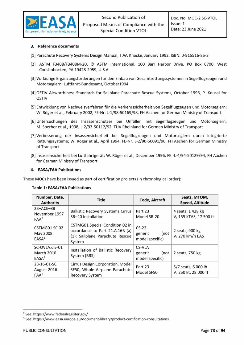
Second Publication of
Proposed Means of Compliance with the Special Condition VTOL
Doc. No: MOC-2 SC-VTOL Issue: 1 Date: 23 June 2021
PUBLIC CONSULTATION Page 73 of 94
Reference documents
[1] Parachute Recovery Systems Design Manual; T.W. Knacke, January 1992, ISBN: 0-915516-85-3
[2] ASTM F3408/F3408M-20, © ASTM International, 100 Barr Harbor Drive, PO Box C700, West Conshohocken, PA 19428-2959, U.S.A.
[3] Vorläufige Ergänzungsforderungen für den Einbau von Gesamtrettungssystemen in Segelflugzeugen und Motorseglern; Luftfahrt-Bundesamt, October1994
[4] OSTIV Airworthiness Standards for Sailplane Parachute Rescue Systems, October 1996, P. Kousal for OSTIV
[5] Entwicklung von Nachweisverfahren für die Verkehrssicherheit von Segelflugzeugen und Motorseglern; W. Röger et al., February 2002, FE-Nr. L-1/98-50169/98, FH Aachen for German Ministry of Transport
[6] Untersuchungen des Insassenschutzes bei Unfällen mit Segelflugzeugen und Motorseglern; M. Sperber et al., 1998, L-2/93-50112/92, TÜV Rheinland for German Ministry of Transport
[7] Verbesserung der Insassensicherheit bei Segelflugzeugen und Motorseglern durch integrierte Rettungssysteme; W. Röger et al., April 1994, FE-Nr. L-2/90-50091/90, FH Aachen for German Ministry of Transport
[8] Insassensicherheit bei Luftfahrtgerät; W. Röger et al., December 1996, FE -L-4/94-50129/94, FH Aachen for German Ministry of Transport
EASA/FAA Publications
These MOCs have been issued as part of certification projects (in chronological order):
Table 1: EASA/FAA Publications
Number, Date, Authority
Title Code, Aircraft Seats, MTOM,
Speed, Altitude
23–ACE–88 November 1997 FAA2
Ballistic Recovery Systems Cirrus SR–20 Installation
Part 23 Model SR-20
4 seats, 1 428 kg Vc 155 KTAS, 17 500 ft
CSTMG01 SC 02 May 2008 EASA3
CSTMG01 Special Condition 02 in accordance to Part 21.A.16B (a) (1): Sailplane Parachute Rescue System
CS-22 generic (not model specific)
2 seats, 900 kg Vc 270 km/h EAS
SC-OVLA.div-01 March 2010 EASA2
Installation of Ballistic Recovery System (BRS)
CS-VLA generic (not model specific)
2 seats, 750 kg
23-16-01-SC August 2016 FAA1
Cirrus Design Corporation, Model SF50; Whole Airplane Parachute Recovery System
Part 23 Model SF50
5/7 seats, 6 000 lb Vc 250 kt, 28 000 ft
2 See: https://www.federalregister.gov/ 3 See: https://www.easa.europa.eu/document-library/product-certification-consultations
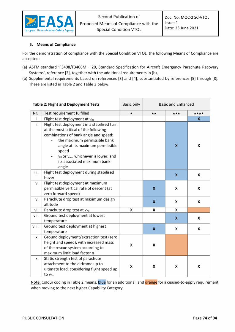
Second Publication of
Proposed Means of Compliance with the Special Condition VTOL
Doc. No: MOC-2 SC-VTOL Issue: 1 Date: 23 June 2021
PUBLIC CONSULTATION Page 74 of 94
Means of Compliance
For the demonstration of compliance with the Special Condition VTOL, the following Means of Compliance are accepted:
(a) ASTM standard ‘F3408/F3408M − 20, Standard Specification for Aircraft Emergency Parachute Recovery
Systems’, reference [2], together with the additional requirements in (b),
(b) Supplemental requirements based on references [3] and [4], substantiated by references [5] through [8].
These are listed in Table 2 and Table 3 below:
Table 2: Flight and Deployment Tests Basic only Basic and Enhanced
Nr. Test requirement fulfilled ⋆ ⋆⋆ ⋆⋆⋆ ⋆⋆⋆⋆ i. Flight test deployment at vne X
ii. Flight test deployment in a stabilised turn at the most critical of the following combinations of bank angle and speed:
- the maximum permissible bank angle at its maximum permissible speed
- vH or vne, whichever is lower, and its associated maximum bank angle
X X
iii. Flight test deployment during stabilised hover
X X
iv. Flight test deployment at maximum permissible vertical rate of descent (at zero forward speed)
X X X
v. Parachute drop test at maximum design altitude
X X X
vi. Parachute drop test at vne X X X
vii. Ground test deployment at lowest temperature
X X
viii. Ground test deployment at highest temperature
X X X
ix. Ground deployment/extraction test (zero height and speed), with increased mass of the rescue system according to maximum limit load factor n
X X
x. Static strength test of parachute attachment to the airframe up to ultimate load, considering flight speed up to vD.
X X X X
Note: Colour coding in Table 2 means, blue for an additional, and orange for a ceased-to-apply requirement
when moving to the next higher Capability Category.
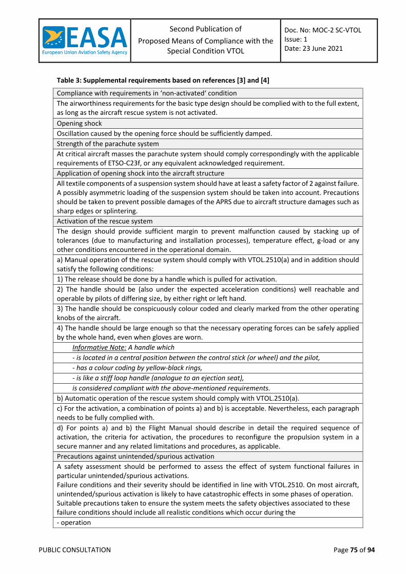
Second Publication of
Proposed Means of Compliance with the Special Condition VTOL
Doc. No: MOC-2 SC-VTOL Issue: 1 Date: 23 June 2021
PUBLIC CONSULTATION Page 75 of 94
Table 3: Supplemental requirements based on references [3] and [4]
Compliance with requirements in ‘non-activated‘ condition
The airworthiness requirements for the basic type design should be complied with to the full extent, as long as the aircraft rescue system is not activated.
Opening shock
Oscillation caused by the opening force should be sufficiently damped.
Strength of the parachute system
At critical aircraft masses the parachute system should comply correspondingly with the applicable requirements of ETSO-C23f, or any equivalent acknowledged requirement.
Application of opening shock into the aircraft structure
All textile components of a suspension system should have at least a safety factor of 2 against failure. A possibly asymmetric loading of the suspension system should be taken into account. Precautions should be taken to prevent possible damages of the APRS due to aircraft structure damages such as sharp edges or splintering.
Activation of the rescue system
The design should provide sufficient margin to prevent malfunction caused by stacking up of tolerances (due to manufacturing and installation processes), temperature effect, g-load or any other conditions encountered in the operational domain.
a) Manual operation of the rescue system should comply with VTOL.2510(a) and in addition should satisfy the following conditions:
1) The release should be done by a handle which is pulled for activation.
2) The handle should be (also under the expected acceleration conditions) well reachable and operable by pilots of differing size, by either right or left hand.
3) The handle should be conspicuously colour coded and clearly marked from the other operating knobs of the aircraft.
4) The handle should be large enough so that the necessary operating forces can be safely applied by the whole hand, even when gloves are worn.
Informative Note: A handle which
- is located in a central position between the control stick (or wheel) and the pilot,
- has a colour coding by yellow-black rings,
- is like a stiff loop handle (analogue to an ejection seat),
is considered compliant with the above-mentioned requirements.
b) Automatic operation of the rescue system should comply with VTOL.2510(a).
c) For the activation, a combination of points a) and b) is acceptable. Nevertheless, each paragraph needs to be fully complied with.
d) For points a) and b) the Flight Manual should describe in detail the required sequence of activation, the criteria for activation, the procedures to reconfigure the propulsion system in a secure manner and any related limitations and procedures, as applicable.
Precautions against unintended/spurious activation
A safety assessment should be performed to assess the effect of system functional failures in particular unintended/spurious activations. Failure conditions and their severity should be identified in line with VTOL.2510. On most aircraft, unintended/spurious activation is likely to have catastrophic effects in some phases of operation. Suitable precautions taken to ensure the system meets the safety objectives associated to these failure conditions should include all realistic conditions which occur during the
- operation
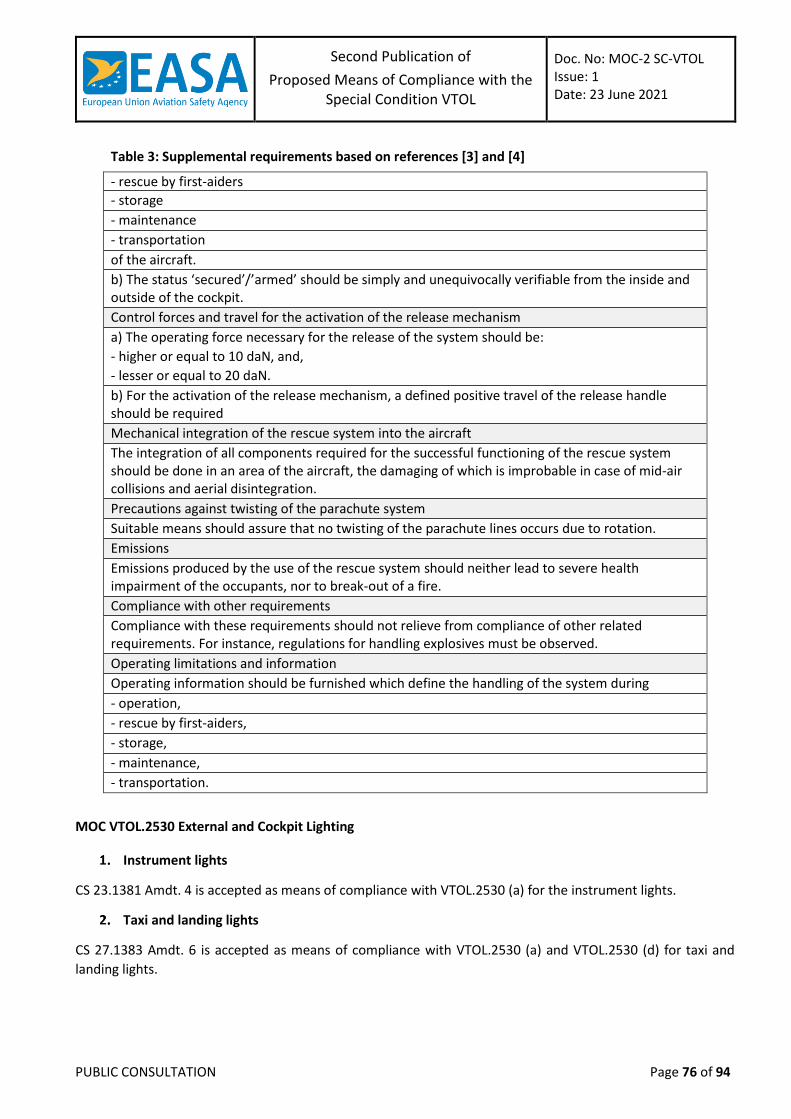
Second Publication of
Proposed Means of Compliance with the Special Condition VTOL
Doc. No: MOC-2 SC-VTOL Issue: 1 Date: 23 June 2021
PUBLIC CONSULTATION Page 76 of 94
Table 3: Supplemental requirements based on references [3] and [4]
- rescue by first-aiders
- storage
- maintenance
- transportation
of the aircraft.
b) The status ‘secured’/’armed’ should be simply and unequivocally verifiable from the inside and outside of the cockpit.
Control forces and travel for the activation of the release mechanism
a) The operating force necessary for the release of the system should be:
- higher or equal to 10 daN, and,
- lesser or equal to 20 daN.
b) For the activation of the release mechanism, a defined positive travel of the release handle should be required
Mechanical integration of the rescue system into the aircraft
The integration of all components required for the successful functioning of the rescue system should be done in an area of the aircraft, the damaging of which is improbable in case of mid-air collisions and aerial disintegration.
Precautions against twisting of the parachute system
Suitable means should assure that no twisting of the parachute lines occurs due to rotation.
Emissions
Emissions produced by the use of the rescue system should neither lead to severe health impairment of the occupants, nor to break-out of a fire.
Compliance with other requirements
Compliance with these requirements should not relieve from compliance of other related requirements. For instance, regulations for handling explosives must be observed.
Operating limitations and information
Operating information should be furnished which define the handling of the system during
- operation,
- rescue by first-aiders,
- storage,
- maintenance,
- transportation.
MOC VTOL.2530 External and Cockpit Lighting
Instrument lights
CS 23.1381 Amdt. 4 is accepted as means of compliance with VTOL.2530 (a) for the instrument lights.
Taxi and landing lights
CS 27.1383 Amdt. 6 is accepted as means of compliance with VTOL.2530 (a) and VTOL.2530 (d) for taxi and
landing lights.
Second Publication of
Proposed Means of Compliance with the Special Condition VTOL
Doc. No: MOC-2 SC-VTOL Issue: 1 Date: 23 June 2021
PUBLIC CONSULTATION Page 77 of 94
Position light
Paragraphs from CS 27.1385 to CS 27.1397 Amdt. 6, both inclusive, are accepted as means of compliance with
VTOL.2530 (a), (b) and (c) for the position lights.
Riding lights
CS 27.1399 Amdt. 6 is accepted as means of compliance with VTOL.2530 (a) and VTOL.2530 (e) for riding lights.
Anti-collision lights
(a) The anti-collision lights are intended to attract attention to the aircraft and they should be designed and
installed to ensure minimum performances in terms of intensities, flash rate, colours and fields of
coverage, in order to be capable to provide sufficient visibility in a timely manner for another aircraft to
avoid a collision. CS 23.1401 Amdt. 4 is accepted as means of compliance with VTOL.2530 (b) and meets
this intent.
(b) In order to show compliance with VTOL.2530 (a), any potential adverse effects of the lights operations
on the satisfactory performance of the flight crew duties should be assessed, for instance cockpit
reflections or any possible effects of rotor or propeller blade strobing.
(c) Other means than (a) may be proposed and agreed with EASA to comply with VTOL.2530(a) and (b).
They may be based either on the outcome of the assessment in (b) or on a different rationale. For
instance, they could also have the purpose to comply with operational or local regulations in the
intended operational environment by preventing harmful dazzle to outside observers, reducing light
pollution, etc. The following examples provide methods that can be acceptable upon agreement with
EASA:
Installation of red anti-collision lights compliant with CS 27.1401 Amdt. 6. The applicant has
to justify that the performances of the lights (intensities, flash rate, colour and fields of
coverage) are sufficient to satisfy the intent of VTOL.2530 (b) for the specific VTOL aircraft
design and operations;
Installation of anti-collision lights compliant with CS 23.1401 Amdt 4 with additional
provisions aimed to adapt and make compatible the intensity of the lights with certain
operational conditions or environments, e.g. by providing means for the flight crew to
reduce the intensity of the lights and switch them off;
Installation of an anti-collision lighting system comprising a combination of lights compliant
with (1) and lights compliant with (2).
MOC VTOL.2535 Safety Equipment
CS27.1411 Amdt. 5 (or later) is accepted as a means of compliance.
For overwater operations, the combination of CS27.1415 Amdt. 5 (or later) and CS29.1415(d) Amdt. 5 (or later)
is accepted as a means of compliance for the installation of additional safety equipment as required by any
applicable operating rule.
Each emergency locator transmitter, including sensors and antennae, required by the applicable operating rule,
should be installed so as to minimise damage that would prevent its functioning following an accident or
incident. (See AMC 27.1470 Amdt. 5 (or later))
Second Publication of
Proposed Means of Compliance with the Special Condition VTOL
Doc. No: MOC-2 SC-VTOL Issue: 1 Date: 23 June 2021
PUBLIC CONSULTATION Page 78 of 94
MOC – SUBPART G – FLIGHT CREW INTERFACE AND OTHER INFORMATION
MOC VTOL.2600 Flight crew compartment
External flight crew view
The following material is intended to serve as guide, highlighting the elements to be considered when developing and assessing the external flight crew view of a VTOL aircraft. It offers a possible method to show compliance with VTOL.2600 for this design element. The function of the external flight crew view in a piloted VTOL aircraft remains the same as assumed for any
other aircraft in their respective Certification Specifications.
In the design phase of the pilot compartment, when considering the external flight crew view, applicants may
therefore choose to start by using the guidance already available in AMC and AC material relevant to 2X.773
“Pilot compartment view”, while keeping in mind the differences related with VTOL aircraft and Innovative Air
Mobility (IAM) Operations. The AMC available for the different Certification Specifications include also Human
Factors considerations.
(a) External crew view functions:
The external field of view should fulfil the following functions:
Provide sufficient external view so that the crew can perform their task of safely controlling
the aircraft flight path.
(i) The external field of view, or visual cues, will need to be assessed depending on the
Flight Controls Laws, Kind of Operations and expected Meteorological Conditions (VMC
or IMC).
(ii) The external visual cues necessary to safely control the aircraft might differ depending
on the phase of flight, as i.e. in the VTOL phase the crew may focus on ground details
(“chin bubbles”) to fly a given trajectory or hold a position, while in forward flight they
might only need to have a visible horizon.
(iii) Depending on the design, the external vision may be used for awareness and/or as a
mitigation of hazards by showing that by having parts of the aircraft visual by the crew,
it is possible to identify abnormal conditions to take proper actions and safely operate
the aircraft.
Provide sufficient external view to see and avoid:
(i) Traffic
(ii) Ground obstacles
(b) External field of view characteristics:
Optical distortions in the windshield or canopy, especially in the prime viewing areas should
be avoided.
The design should allow for sufficient external field of view free of obstruction. Account can
be taken of aircraft specific features (as “chin bubbles”) that provide the crew with sufficient
visible external cues, in all day/night and weather conditions expected in operation.
The need for windshield wipers or precipitation/snow removing devices/features should be
considered.
Second Publication of
Proposed Means of Compliance with the Special Condition VTOL
Doc. No: MOC-2 SC-VTOL Issue: 1 Date: 23 June 2021
PUBLIC CONSULTATION Page 79 of 94
The area of the pilot compartment field of view that according with FAA AC 27.7734 should
be free from obstruction should be used as starting point for the design: years of experience
show that this obstruction free area has ensured the functions listed in (a).
(i) when using this material, applicants should consider the differences between the VTOL
expected trajectories and flight attitudes envelope compared to conventional aircraft,
and the CONOPS that will be carried out by the crew in terms of traffic/obstacle “see
and avoid”.
(ii) deviations from the current material can be justified by the reasons in (i) but also by
design characteristics of the VTOL aircraft (canards, lift/thrust systems forward of the
crew compartment view).
(iii) any obstructions should be assessed, and the suitability of the external field of view
evaluated, in the entire flight test domain against its intended functions in the CONOPS.
If, for design reasons, the available external field of view does not allow the crew to perform
their duties, the applicant may show compliance by using synthetic cues displayed to the
crew. These synthetic cues should be introduced as soon as possible in the design and be
thoroughly assessed during the complete flight test campaign.
(c) Single panel windshield:
According to VTOL.2600 (c), for category Enhanced, the flight crew interface design must allow for
continued safe flight and landing after loss of vision through any one of the windshield panels. If the
design however is a single panel windshield, the applicant can demonstrate by analysis and/or flight test
that the loss of vision through the single panel is partial and that the remaining external field of view
will allow for continued safe flight and landing.
(d) Flight in precipitation5:
The external field of view should be sufficient in day/night, and not impaired by
precipitation conditions.
(e) Flight in snow conditions:
CS-27 and AMC-27 contain no specific requirement or guidance for visibility in snow conditions, to protect against potential accumulation of snow on windshield and windows. In particular, no reference to falling and blowing snow is made in CS 27.773 . So far, the pilot view obstruction in snow conditions has been addressed by the European Light Helicopter Manufacturers and the European Airworthiness Authorities during flight test demonstration for a turbine engine installation, as requested by the CS 27.1093(c). During these flight tests for helicopters powered by turbine engine, snow accretion was sometimes observed on the helicopter windshield, leading to a dangerous reduction in pilot view. In these instances, only the use of wipers was able to restore acceptable visibility. The Standardised European Rules of the Air establish in SERA.5010 the conditions under which an ATC unit can authorise a helicopter to operate within a control zone under Special VFR clearance, including certain weather minima. Therefore, it is assumed that a helicopter certified for day and night VFR can perform hover flights in re-circulating snow, take-off and land under snow falls, and fly with falling snow compatible with the Special VFR limit visibility.
4 AC 27.773 from FAA AC 27-1B Change 7 constitutes the EASA AMC with CS 27.773 5 Flight into known icing conditions is out of the scope of this MOC.
Second Publication of
Proposed Means of Compliance with the Special Condition VTOL
Doc. No: MOC-2 SC-VTOL Issue: 1 Date: 23 June 2021
PUBLIC CONSULTATION Page 80 of 94
Since the SERA Special VFR rules could still be applicable for VTOL aircraft, it is necessary to consider the pilot view of the flight path during a flight in snow fall that is compatible with these weather minima.
The external field of view should be sufficient in day/night, and not impaired by snow
conditions.
If certification for flight in snow conditions is requested, it should be demonstrated that
snow, both falling and blowing, does not accumulate on the VTOL windshield and windows
so that crew external view of the flight path and surroundings is not unduly impaired during
taxiing, hover flight, take-off, level flight and landing. Normal operations with no hazardous
reduction in the pilot’s view of the flight path should be demonstrated under the following:
(i) Conditions to ensure VTOL operation in falling and blowing snow without restriction:
(A) Visibility: ½ mile as limited by snow, which represents a moderate/heavy snowstorm
and is also consistent with the weather minima compatible with Special VFR. This
value is a test parameter rather than an operational limitation to be imposed on the
VTOL after the tests are completed.
(B) Temperature:
Unless other temperatures are deemed more critical, -4°C to +1°C (25°F
to 34°F) being -2°C to +1°C desirable (28°F to 34°F) should be used, as
conducive to wet snow conditions, which tends to accumulate on
unheated surfaces subject to impingement.
Company development testing or experience with similar VTOL may be
adequate to determine other critical ambient conditions for
certification testing.
(C) Operations:
Operation Minimum Test Duration
Ground operations 20 minutes
IGE hover 5 minutes
Level flight 1 hour
Descent and landing -
Ground running, taxiing, and IGE hover operations are generally the
most critical since the VTOL may be operating in recirculating snow.
Twenty-five minutes, or the maximum allowed time in relation the
aircraft limitations, under these extreme conditions is considered a
reasonable maximum, both from the view of pilot stress and the
maximum expected taxi time prior to take off in bad weather.
One hour of level flight operation, or maximum expected flight
duration, under ½-mile visibility snow conditions is deemed to provide
ample opportunity for accumulation to begin to build.
The durations reported in the table above are minimum test duration
times based on experience with rotorcraft operations, to ensure that
the snow accretion on the aircraft and windshield is representative of a
worst-case scenario. Different durations can be agreed with EASA
depending on the actual aircraft limitations or the expected operations.
Second Publication of
Proposed Means of Compliance with the Special Condition VTOL
Doc. No: MOC-2 SC-VTOL Issue: 1 Date: 23 June 2021
PUBLIC CONSULTATION Page 81 of 94
(D) Provisions in the Aircraft Flight Manual:
Visibility restrictions or limitations, based on which falling and blowing
snow operations can be allowed, are not considered appropriate, as
visibility may fluctuate rapidly in snowstorms. It is affected by the
presence of fog or ice crystals, is not crew measured or controlled, and
is difficult to estimate.
Time limitations, other than possibly for ground and hover operations,
are not considered appropriate:
1. Since during cruise in snow conditions the aircraft is likely to be in
and out of heavy snowfall, it is not practical for the crew to measure
the time spent in snow in level flight conditions. Thus, it is not
appropriate to include time limitations in the AFM for level flight
snow operations.
2. A practical ground and IGE hover time limitation of less than 25
minutes, or the maximum allowed time in relation the aircraft
limitations, in recirculating snow may be considered. The expected
action at the expiration of this specified time would be landing or
transition to a safe flight condition where it has been shown that
snow accumulations will not intensify or shed and so not cause
unacceptable reduction in pilot visibility.
(ii) Artificially produced snow should not be used as the sole means of showing
compliance. While it is an excellent development tool, artificial snow production devices
are usually restricted to use for hover and ground evaluations, and the snow pellets
produced by these machines are not sufficiently similar to natural snowflakes to justify
the use of artificial snow as the sole basis of certification.
Other test conditions:
(i) The windshield and windows should remain free of excessive snow accumulation.
Excessive accumulation is defined as accumulation that may cause hazardous reduction
in crew’s view of the flight path.
(ii) Actual flight demonstration should be performed in natural snow. The ground
operations and IGE hover test conditions assume operation in recirculating snow.
Blowing snow, resulting from rotor airflow recirculation, can be expected to be more
severe than natural blowing snow if the VTOL continues to move slowly over freshly
fallen snow. Thus, the blowing snow operational capability should be demonstrated by
the taxi and hover operations in recirculating snow.
(iii) Airspeeds:
(A) For VFR VTOL aircraft, the airspeeds for the level flight test condition should include
the maximum consistent with the visibility conditions.
(B) For IFR operations, the airspeed should range from the minimum IFR speed or the
minimum for snow operations up to the maximum cruise speed or the maximum
speed specified for snow operations in the flight manual limitations, unless other
airspeeds are deemed more critical. VTOL seeking VFR certification may later be IFR
Second Publication of
Proposed Means of Compliance with the Special Condition VTOL
Doc. No: MOC-2 SC-VTOL Issue: 1 Date: 23 June 2021
PUBLIC CONSULTATION Page 82 of 94
certified with a possible increase in airspeed in snow conditions. This factor should
be considered if IFR certification is anticipated.
(iv) Visibility measurements:
(A) The specified visibility assumes that visual measurements are made in falling snow
in the absence of fog or recirculating snow by an observer at the test site outside the
tests VTOL’s area of influence.
(B) An accepted equation for relating this measured visibility to snow concentration is V
= 374.9/C0.7734 where C is the snow concentration (grams/meter3) and V is the
visibility (meters).
This equation can be reasonably applied to all snowflake type
classifications and is credited to J.R. Stallabrass, National Research
Council of Canada.
Other equations may be applied if they are shown to be accurate for
the particular snowflake types for the test program.
(v) The likelihood that the desired concentration will exist for the duration of the testing is
even more remote. Because of these testing realities, it is very likely that exact target
test conditions will not be achieved. Those involved in certification must exercise good
judgment in accepting alternate approaches. However, the applicant should strive to
perform the test in conditions as close as practicable to ½ mile visibility.
(vi) If it becomes apparent that snow accumulations in ground and IGE hover operations in
recirculating snow are much more severe than in the level flight test, it is reasonable to
accept prolonged IGE operations in recirculating snow and to accept durations of less
than 1-hour level flight, or maximum expected flight duration. Best efforts should be
made to assure that at least some level flight time is accomplished at ½-mile visibility to
assure that the spectrum is covered.
(vii) For the level flight portion, if after a reasonable time it is noticed that there is no snow
accumulation that would impair the pilot visibility, the duration of the level flight may
be reduced accordingly.
(viii) It should be determined that the visibility established at the test site is limited
by snow and not by fog or poor lighting (twilight) conditions.
(ix) Recirculation is necessarily a qualitative judgment by the test pilot. For test purposes,
recirculation should be the highest snow concentration attainable in the manoeuvre, or
that corresponding to the lowest visibility at which (in the pilot’s judgment) control of
the VTOL is possible in the IGE condition. The visibility specification of ½ mile outside of
the recirculation influence becomes inconsequential provided that fresh, loose snow is
continually experienced during the ground operation and IGE hover testing phase.
However, since it is intended that the test phases be accomplished sequentially to
assure that transition to take off and other transients are considered, the conditions at
take off, level flight, and descent and landing should approximate the ½-mile visibility
criteria.
Second Publication of
Proposed Means of Compliance with the Special Condition VTOL
Doc. No: MOC-2 SC-VTOL Issue: 1 Date: 23 June 2021
PUBLIC CONSULTATION Page 83 of 94
Controls and displays for use by the flight crew:
CS 27.1302 Amdt. 8, as per the guidelines defined in its AMC 27.1302, is accepted as a means of compliance with VTOL.2600 regarding the design and approval of installed equipment that is intended for use by the crew members from their normal seating positions in the cockpit with the following considerations:
(a) CS 27.1302 and its AMC 27.1302 apply to the crew interfaces and system behaviour for all the installed
systems and equipment used by the crew in the cockpit while operating the VTOL aircraft in normal,
abnormal/malfunction and emergency conditions.
(b) The functions of the crew members operating from the cabin need to be considered if they may interfere
with the ones under the responsibility of the cockpit crew, or if dedicated airworthiness requirements
are included in the rules.
(c) CS 27.1302 and its AMC do not apply to crew training, qualification, or licensing requirements.
(d) The extent of the compliance demonstration necessary for each design may vary and not all the material
contained in this MOC has to be systematically followed. The proportionate application of AMC 27.1302
will depend on criteria such as the VTOL category (Enhanced and Basic) and the maximum passenger
seating configuration.
Explanatory Note: The Categories Basic and Enhanced were introduced in the Special Condition to allow proportionality in safety objectives. It is considered that the safety objectives for CS-25 and CS-27/29 aircraft should be maintained as a minimum for VTOL aircraft in the Category Enhanced, i.e. intended for operations over congested areas or for commercial air transport of passengers. The same approach is followed in the implementation of Human Factors during the design and certification processes of VTOL cockpits. For the Category Basic, proportionality is allowed in the application of AMC 27.1302 as defined in this MOC VTOL.2600.
Second Publication of
Proposed Means of Compliance with the Special Condition VTOL
Doc. No: MOC-2 SC-VTOL Issue: 1 Date: 23 June 2021
PUBLIC CONSULTATION Page 84 of 94
(e) The following proportional approach in the application of AMC 27.1302 supersedes AMC 27.1302
paragraph 3.2.9 “Proportional approach in the compliance demonstration”:
Maximum
Passenger
Seating
Configuration
Proportionality
Category
Enhanced - Applicants for a VTOL aircraft should follow all provisions in AMC 27.1302.
Category
Basic
7 to 9
passengers Applicants for a VTOL aircraft should follow all provisions in AMC 27.1302.
2 to 6
passengers
Applicants for a VTOL aircraft are:
i. not required to develop a dedicated HFs test programme
and
ii. allowed to use single occurrence of a test for compliance
demonstration;
0 to 1
passenger
Applicants for a VTOL aircraft are:
i. not required to develop a dedicated HFs test programme;
ii. allowed to use single occurrence of a test for compliance
demonstration;
iii. allowed to use a single crew to demonstrate the HFs scenario
based assessments.
MOC VTOL.2605 Installation and operation information
(a) For compliance with VTOL.2605(a):
The use of alphabetic or numerical symbols will be acceptable if recognition depends upon
reference to a master key and any relation between symbol and function is carefully
avoided.
Specification ISO.12 version 2ED 1987 describes acceptable graphical markings.
(b) CS 27.1322 Amdt 21, as per the guidelines established in AMC 25.1322, is accepted as a means of
compliance with VTOL.2605(b) regarding the design of warnings, cautions and advisory lights.
(c) CS 27.1302 Amdt. 8, as per the guidelines established in AMC 27.1302, is accepted as a means of
compliance with VTOL.2605(b) and (c) regarding the design of crew interfaces and behaviour of installed
systems and equipment used by the crew in the cockpit while operating the VTOL aircraft in normal,
abnormal abnormal/malfunction and emergency conditions.
The functions of the crew members operating from the cabin should be considered if they
may interfere with the ones under the responsibility of the cockpit crew, or if dedicated
airworthiness requirements apply.
CS 27.1302 and its AMC 27.1302 do not apply to crew training, qualification, or licensing
requirements.
The extent of the compliance demonstration necessary for each design may vary and not all
the material contained in this MOC has to be systematically followed. The proportionate
application of AMC 27.1302 will depend on criteria such as VTOL category (Enhanced and
Basic) and the maximum passenger seating configuration.
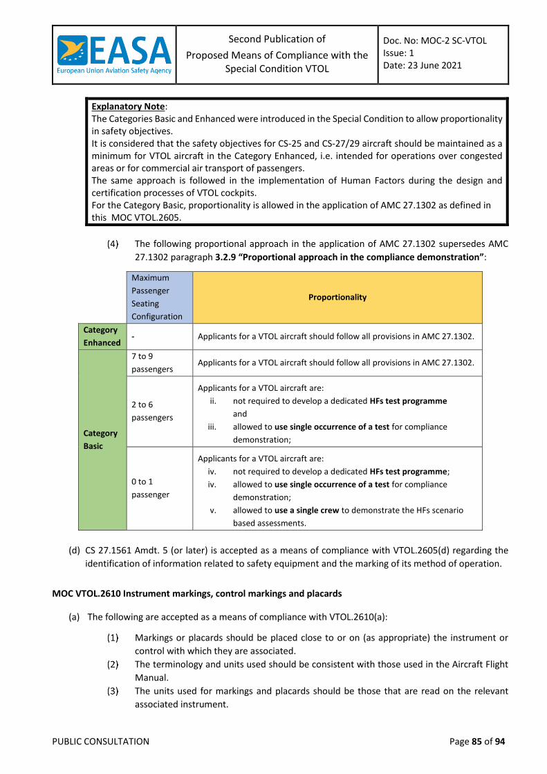
Second Publication of
Proposed Means of Compliance with the Special Condition VTOL
Doc. No: MOC-2 SC-VTOL Issue: 1 Date: 23 June 2021
PUBLIC CONSULTATION Page 85 of 94
Explanatory Note: The Categories Basic and Enhanced were introduced in the Special Condition to allow proportionality in safety objectives. It is considered that the safety objectives for CS-25 and CS-27/29 aircraft should be maintained as a minimum for VTOL aircraft in the Category Enhanced, i.e. intended for operations over congested areas or for commercial air transport of passengers. The same approach is followed in the implementation of Human Factors during the design and certification processes of VTOL cockpits. For the Category Basic, proportionality is allowed in the application of AMC 27.1302 as defined in this MOC VTOL.2605.
The following proportional approach in the application of AMC 27.1302 supersedes AMC
27.1302 paragraph 3.2.9 “Proportional approach in the compliance demonstration”:
Maximum
Passenger
Seating
Configuration
Proportionality
Category
Enhanced - Applicants for a VTOL aircraft should follow all provisions in AMC 27.1302.
Category
Basic
7 to 9
passengers Applicants for a VTOL aircraft should follow all provisions in AMC 27.1302.
2 to 6
passengers
Applicants for a VTOL aircraft are:
ii. not required to develop a dedicated HFs test programme
and
iii. allowed to use single occurrence of a test for compliance
demonstration;
0 to 1
passenger
Applicants for a VTOL aircraft are:
iv. not required to develop a dedicated HFs test programme;
iv. allowed to use single occurrence of a test for compliance
demonstration;
v. allowed to use a single crew to demonstrate the HFs scenario
based assessments.
(d) CS 27.1561 Amdt. 5 (or later) is accepted as a means of compliance with VTOL.2605(d) regarding the
identification of information related to safety equipment and the marking of its method of operation.
MOC VTOL.2610 Instrument markings, control markings and placards
(a) The following are accepted as a means of compliance with VTOL.2610(a):
Markings or placards should be placed close to or on (as appropriate) the instrument or
control with which they are associated.
The terminology and units used should be consistent with those used in the Aircraft Flight
Manual.
The units used for markings and placards should be those that are read on the relevant
associated instrument.
Second Publication of
Proposed Means of Compliance with the Special Condition VTOL
Doc. No: MOC-2 SC-VTOL Issue: 1 Date: 23 June 2021
PUBLIC CONSULTATION Page 86 of 94
Publications which are considered to provide appropriate standards for the design
substantiation and certification of symbolic placards may include, but are not limited to,
‘General Aviation Manufacturers Association (GAMA) Publication No. 15 — Symbolic
Messages’, Initial Issue, 1 March 2014.
AMC 1 to 23.2610 Amdt. 5 is accepted as additional MOC with VTOL.2610(a)
(b) CS 27.1555 (a), (b)(1) and (2), and (e) Amdt.6 are accepted as means of compliance with VTOL.2610(b).
(c) If certification with ditching provisions, emergency flotation provisions or limited over water operations
is requested by the applicant, each emergency control that may need to be operated underwater should
be marked with the method of operation and be marked with yellow and black stripes.
MOC VTOL.2620 Electronic Aircraft Flight Manual
INTRODUCTION AND SCOPE
This MOC presents guidelines for obtaining approval of an electronic version of an Aircraft Flight Manual (eAFM).
These guidelines also apply to eAFM appendices and supplements. The guidelines are applicable to eAFM
applications running on hardware platforms which may or may not be included in the aircraft type design
definition.
(a) These guidelines cover:
The definitions of the eAFM and its constituents, as well as its relationship with the EFB
world;
The expected process for airworthiness approval of the eAFM;
The acceptable means to ensure:
(i) completeness and integrity of the eAFM, as well as the means for ensuring control of its
configuration and of the information thereby provided;
(ii) management of supplemental information regarding specific aircraft configurations and
removable kits;
(iii) approval of post-TC eAFM revisions, either stand alone or design change related,
including those done by third parties and those resulting from continuing airworthiness
processes.
(b) These guidelines do not cover:
Systems that provide input to other aircraft systems or equipment;
Supplementary software or software functions used to prepare documentation suitable for
use in the operation of the aircraft under the applicable operating rules (e.g. airport analysis
software).
(c) Similarly to a paper AFM, eAFM software application is not certified as part of the aircraft type design,
however it is approved by EASA for showing compliance with VTOL.2620.
(d) The operational rules (Commission Regulation (EU) No 965/2012 and subsequent amendments) include
provisions for the use of an eAFM. However, from an airworthiness approval standpoint, the showing of
compliance of the aircraft eAFM with the TC basis requirements should be based on this MOC.
Second Publication of
Proposed Means of Compliance with the Special Condition VTOL
Doc. No: MOC-2 SC-VTOL Issue: 1 Date: 23 June 2021
PUBLIC CONSULTATION Page 87 of 94
Definitions
The primary purpose of the AFM required by VTOL.2620 is to provide an authoritative source of information
necessary for the safe operation of the aircraft. In this aim, it is based in the first place on source technical data
files from which all required AFM information must be gathered, classified, organized, and prioritized. These
data files need to be processed by a specific software application to allow interactive display of the information
in a given format and structure. The eAFM software application may run on different kinds of host platforms
with various hardware and operating systems.
The following definitions apply:
(a) Electronic AFM (eAFM): Set of data files and a software application used to provide interactive display
of AFM information on an authorised host platform.
(b) Software Application: The software program(s), installation information and operating guide to be used
by the end user in conjunction with the data files to display the eAFM information.
(c) Host Platform: The hardware and basic software (e.g. Operative System (OS), input/output software)
environment that enables the operation of the software application to input, process and output the
eAFM information to the end user.
(d) Authorised host platform configuration: Host platform configuration with characteristics (e.g.
input/output hardware characteristics, Operating System version, Central Processing Unit (CPU) type,
CPU frequency, memory) for which the eAFM performance and integrity are guaranteed.
Note: Particular cases of authorised host platform configuration are the “worst case authorised host
platform configurations” that correspond to the configurations with minimum characteristics ensuring
the eAFM performance and integrity.
eAFM scope of approval and deliverable data package
The approved constituents of an eAFM are the data files and the software application(s). The host platform is
not part of the approved eAFM. If it is not part of the type design definition (e.g. in the case of non-installed
equipment such as portable COTS equipment), the list of host platform configuration characteristics and their
authorised range will be identified as conditions for the eAFM approval.
Therefore, the following information should be clearly identified and made available with each aircraft:
(a) The eAFM data files applicable to that aircraft, i.e. name, format, version, and date.
(b) The eAFM software application(s), i.e. name, version, part number, installation information (including
verification procedure, see Section 5(b)(3) in this MOC) and operating guide.
(c) If the host platform is non-installed equipment (not part of the type design definition), the list of
authorised host platform configuration characteristics and the range in which those characteristics may
evolve while ensuring the correct performance of the eAFM.
Compliance demonstration
(a) The following eAFM aspects should be addressed in the demonstration of compliance with VTOL.2620:
The technical content of the approved AFM information (e.g. Limitations, Normal and
Emergency procedures, Performance data, etc.);
The structure of this technical content, i.e. the way the different sections, subsections and
single information of the eAFM are ordered and structured in relation with each other;
The eAFM information format, i.e. the way the technical content and structure of the eAFM
are displayed.
Second Publication of
Proposed Means of Compliance with the Special Condition VTOL
Doc. No: MOC-2 SC-VTOL Issue: 1 Date: 23 June 2021
PUBLIC CONSULTATION Page 88 of 94
(b) The software application(s) should ensure at any time segregation and clear distinction of the approved
data from non-approved ones, in particular when interactive functions of the software are in use. The
software should always show if any information is approved (by indication of the approval status and
approving organisation/authority) or belongs to the non-approved part of the AFM.
(c) Identification of the approval status of the eAFM (data file version, SW application version, etc.) should be made readily available to the end user via a dedicated function or permanently displayed. The eAFM should be under configuration management control and a unique identifier covering all the eAFM constituents should be available.
(d) Practical access to, and readability and usability of, the eAFM information on ground, in flight, and during
any foreseeable normal and emergency operating condition should be also demonstrated.
Software considerations
(a) The integrity and reliability of the eAFM software application(s) running on an authorised host platform
should be commensurate with the safety objectives defined for their identified failure conditions.
(b) Software running on non-installed equipment:
If the software application is intended to be installed on non-installed equipment, not part
of the type design definition, such as Commercial Off-the-Shelf (COTS) platforms and
possibly under control by the operator, the lack of development assurance of the platform
should be compensated for by at least the following:
(i) Development assurance activities at application level; and
(ii) Verification at eAFM end user level (operator).
A software development assurance process for the eAFM software application(s) should be
defined and implemented. It should include in particular extensive6 verification of the eAFM
functionality, including robustness test cases, in a repeatable and standardised manner and
for the worst-case authorised platform configurations. This could be achieved by means of
development assurance processes (e.g. DO-178()/ED-12(), DO-330/ED-215...) or other
appropriate means to be agreed by EASA.
An additional verification procedure should be developed and provided to end users, as part
of the eAFM installation information, for them to ensure adequate verification of the eAFM
functionality on their final host platform configuration(s). It should also provide information
on how to ensure the absence of regression in case of new or updated host platforms (e.g.
Operating System update) or when new software application versions are released.
(c) eAFM data files: The integrity of the eAFM information should be ensured, e.g. by means of CRC
protection of the data files.
(d) Identification of the authorized host platform characteristics
The host platform will not be part of the EASA approved eAFM.
The host platform can consist of COTS equipment, without software or hardware
qualification, whose technological and performance features as available on the market
may change very rapidly. Therefore, the specifications of the host platform configuration
characteristics for which the eAFM performance and integrity are guaranteed should be
provided.
6 “Extensive” means that all possible eAFM functionalities have been covered by the verification.
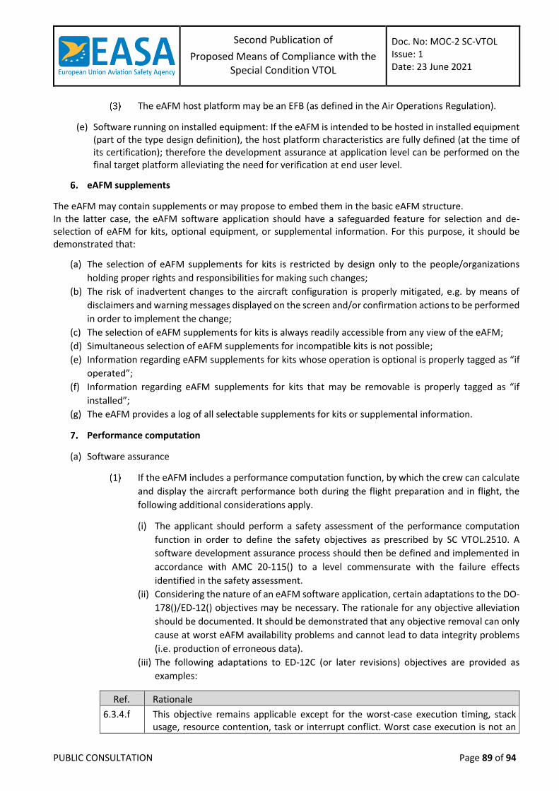
Second Publication of
Proposed Means of Compliance with the Special Condition VTOL
Doc. No: MOC-2 SC-VTOL Issue: 1 Date: 23 June 2021
PUBLIC CONSULTATION Page 89 of 94
The eAFM host platform may be an EFB (as defined in the Air Operations Regulation).
(e) Software running on installed equipment: If the eAFM is intended to be hosted in installed equipment (part of the type design definition), the host platform characteristics are fully defined (at the time of its certification); therefore the development assurance at application level can be performed on the final target platform alleviating the need for verification at end user level.
eAFM supplements
The eAFM may contain supplements or may propose to embed them in the basic eAFM structure. In the latter case, the eAFM software application should have a safeguarded feature for selection and de-selection of eAFM for kits, optional equipment, or supplemental information. For this purpose, it should be demonstrated that:
(a) The selection of eAFM supplements for kits is restricted by design only to the people/organizations
holding proper rights and responsibilities for making such changes;
(b) The risk of inadvertent changes to the aircraft configuration is properly mitigated, e.g. by means of
disclaimers and warning messages displayed on the screen and/or confirmation actions to be performed
in order to implement the change;
(c) The selection of eAFM supplements for kits is always readily accessible from any view of the eAFM;
(d) Simultaneous selection of eAFM supplements for incompatible kits is not possible;
(e) Information regarding eAFM supplements for kits whose operation is optional is properly tagged as “if
operated”;
(f) Information regarding eAFM supplements for kits that may be removable is properly tagged as “if
installed”;
(g) The eAFM provides a log of all selectable supplements for kits or supplemental information.
Performance computation
(a) Software assurance
If the eAFM includes a performance computation function, by which the crew can calculate
and display the aircraft performance both during the flight preparation and in flight, the
following additional considerations apply.
(i) The applicant should perform a safety assessment of the performance computation
function in order to define the safety objectives as prescribed by SC VTOL.2510. A
software development assurance process should then be defined and implemented in
accordance with AMC 20-115() to a level commensurate with the failure effects
identified in the safety assessment.
(ii) Considering the nature of an eAFM software application, certain adaptations to the DO-
178()/ED-12() objectives may be necessary. The rationale for any objective alleviation
should be documented. It should be demonstrated that any objective removal can only
cause at worst eAFM availability problems and cannot lead to data integrity problems
(i.e. production of erroneous data).
(iii) The following adaptations to ED-12C (or later revisions) objectives are provided as
examples:
Ref. Rationale
6.3.4.f This objective remains applicable except for the worst-case execution timing, stack usage, resource contention, task or interrupt conflict. Worst case execution is not an
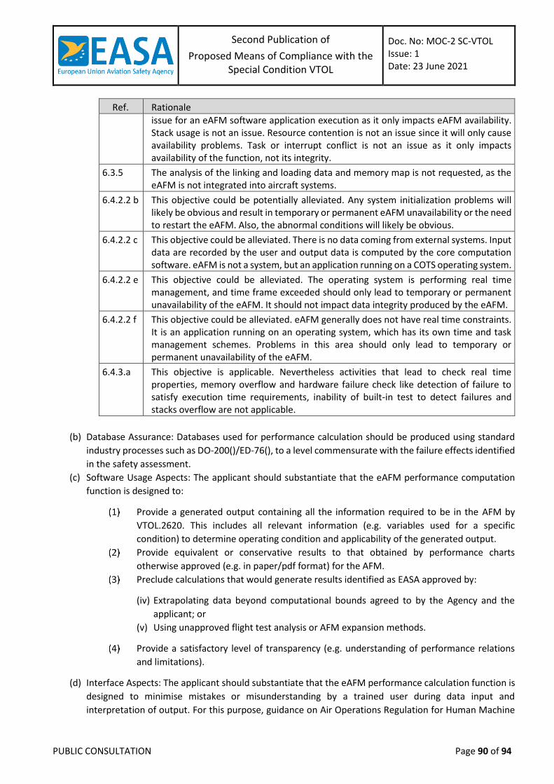
Second Publication of
Proposed Means of Compliance with the Special Condition VTOL
Doc. No: MOC-2 SC-VTOL Issue: 1 Date: 23 June 2021
PUBLIC CONSULTATION Page 90 of 94
Ref. Rationale
issue for an eAFM software application execution as it only impacts eAFM availability. Stack usage is not an issue. Resource contention is not an issue since it will only cause availability problems. Task or interrupt conflict is not an issue as it only impacts availability of the function, not its integrity.
6.3.5 The analysis of the linking and loading data and memory map is not requested, as the eAFM is not integrated into aircraft systems.
6.4.2.2 b This objective could be potentially alleviated. Any system initialization problems will likely be obvious and result in temporary or permanent eAFM unavailability or the need to restart the eAFM. Also, the abnormal conditions will likely be obvious.
6.4.2.2 c This objective could be alleviated. There is no data coming from external systems. Input data are recorded by the user and output data is computed by the core computation software. eAFM is not a system, but an application running on a COTS operating system.
6.4.2.2 e This objective could be alleviated. The operating system is performing real time management, and time frame exceeded should only lead to temporary or permanent unavailability of the eAFM. It should not impact data integrity produced by the eAFM.
6.4.2.2 f This objective could be alleviated. eAFM generally does not have real time constraints. It is an application running on an operating system, which has its own time and task management schemes. Problems in this area should only lead to temporary or permanent unavailability of the eAFM.
6.4.3.a This objective is applicable. Nevertheless activities that lead to check real time properties, memory overflow and hardware failure check like detection of failure to satisfy execution time requirements, inability of built-in test to detect failures and stacks overflow are not applicable.
(b) Database Assurance: Databases used for performance calculation should be produced using standard
industry processes such as DO-200()/ED-76(), to a level commensurate with the failure effects identified
in the safety assessment.
(c) Software Usage Aspects: The applicant should substantiate that the eAFM performance computation
function is designed to:
Provide a generated output containing all the information required to be in the AFM by
VTOL.2620. This includes all relevant information (e.g. variables used for a specific
condition) to determine operating condition and applicability of the generated output.
Provide equivalent or conservative results to that obtained by performance charts
otherwise approved (e.g. in paper/pdf format) for the AFM.
Preclude calculations that would generate results identified as EASA approved by:
(iv) Extrapolating data beyond computational bounds agreed to by the Agency and the
applicant; or
(v) Using unapproved flight test analysis or AFM expansion methods.
Provide a satisfactory level of transparency (e.g. understanding of performance relations
and limitations).
(d) Interface Aspects: The applicant should substantiate that the eAFM performance calculation function is
designed to minimise mistakes or misunderstanding by a trained user during data input and
interpretation of output. For this purpose, guidance on Air Operations Regulation for Human Machine
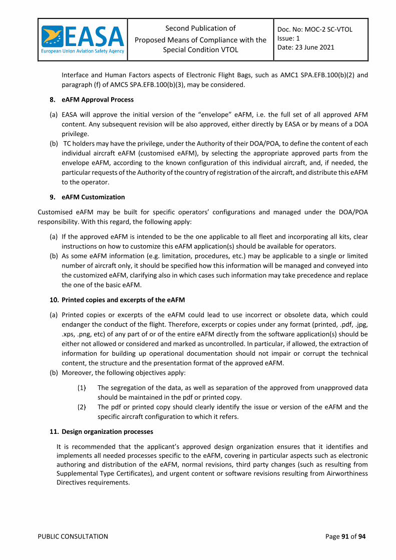
Second Publication of
Proposed Means of Compliance with the Special Condition VTOL
Doc. No: MOC-2 SC-VTOL Issue: 1 Date: 23 June 2021
PUBLIC CONSULTATION Page 91 of 94
Interface and Human Factors aspects of Electronic Flight Bags, such as AMC1 SPA.EFB.100(b)(2) and
paragraph (f) of AMC5 SPA.EFB.100(b)(3), may be considered.
eAFM Approval Process
(a) EASA will approve the initial version of the “envelope” eAFM, i.e. the full set of all approved AFM
content. Any subsequent revision will be also approved, either directly by EASA or by means of a DOA
privilege.
(b) TC holders may have the privilege, under the Authority of their DOA/POA, to define the content of each
individual aircraft eAFM (customised eAFM), by selecting the appropriate approved parts from the
envelope eAFM, according to the known configuration of this individual aircraft, and, if needed, the
particular requests of the Authority of the country of registration of the aircraft, and distribute this eAFM
to the operator.
eAFM Customization
Customised eAFM may be built for specific operators’ configurations and managed under the DOA/POA
responsibility. With this regard, the following apply:
(a) If the approved eAFM is intended to be the one applicable to all fleet and incorporating all kits, clear
instructions on how to customize this eAFM application(s) should be available for operators.
(b) As some eAFM information (e.g. limitation, procedures, etc.) may be applicable to a single or limited
number of aircraft only, it should be specified how this information will be managed and conveyed into
the customized eAFM, clarifying also in which cases such information may take precedence and replace
the one of the basic eAFM.
Printed copies and excerpts of the eAFM
(a) Printed copies or excerpts of the eAFM could lead to use incorrect or obsolete data, which could
endanger the conduct of the flight. Therefore, excerpts or copies under any format (printed, .pdf, .jpg,
.xps, .png, etc) of any part of or of the entire eAFM directly from the software application(s) should be
either not allowed or considered and marked as uncontrolled. In particular, if allowed, the extraction of
information for building up operational documentation should not impair or corrupt the technical
content, the structure and the presentation format of the approved eAFM.
(b) Moreover, the following objectives apply:
The segregation of the data, as well as separation of the approved from unapproved data
should be maintained in the pdf or printed copy.
The pdf or printed copy should clearly identify the issue or version of the eAFM and the
specific aircraft configuration to which it refers.
Design organization processes
It is recommended that the applicant’s approved design organization ensures that it identifies and implements all needed processes specific to the eAFM, covering in particular aspects such as electronic authoring and distribution of the eAFM, normal revisions, third party changes (such as resulting from Supplemental Type Certificates), and urgent content or software revisions resulting from Airworthiness Directives requirements.
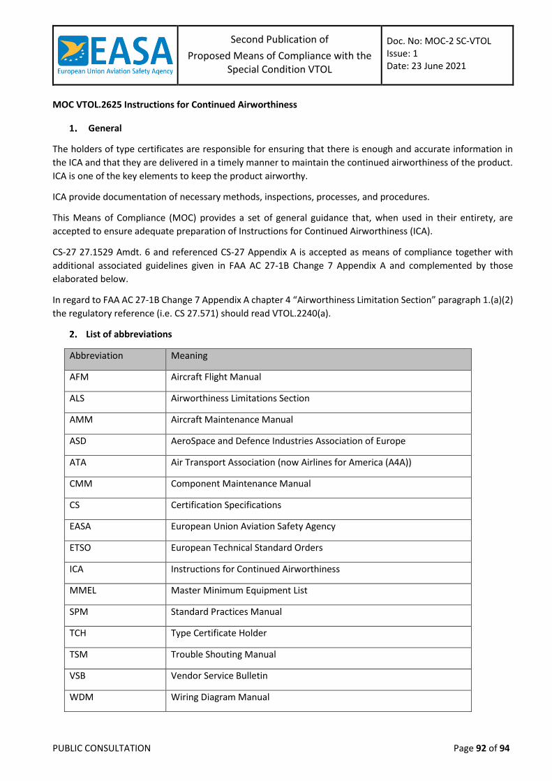
Second Publication of
Proposed Means of Compliance with the Special Condition VTOL
Doc. No: MOC-2 SC-VTOL Issue: 1 Date: 23 June 2021
PUBLIC CONSULTATION Page 92 of 94
MOC VTOL.2625 Instructions for Continued Airworthiness
General
The holders of type certificates are responsible for ensuring that there is enough and accurate information in
the ICA and that they are delivered in a timely manner to maintain the continued airworthiness of the product.
ICA is one of the key elements to keep the product airworthy.
ICA provide documentation of necessary methods, inspections, processes, and procedures.
This Means of Compliance (MOC) provides a set of general guidance that, when used in their entirety, are
accepted to ensure adequate preparation of Instructions for Continued Airworthiness (ICA).
CS-27 27.1529 Amdt. 6 and referenced CS-27 Appendix A is accepted as means of compliance together with
additional associated guidelines given in FAA AC 27-1B Change 7 Appendix A and complemented by those
elaborated below.
In regard to FAA AC 27-1B Change 7 Appendix A chapter 4 “Airworthiness Limitation Section” paragraph 1.(a)(2)
the regulatory reference (i.e. CS 27.571) should read VTOL.2240(a).
List of abbreviations
Abbreviation Meaning
AFM Aircraft Flight Manual
ALS Airworthiness Limitations Section
AMM Aircraft Maintenance Manual
ASD AeroSpace and Defence Industries Association of Europe
ATA Air Transport Association (now Airlines for America (A4A))
CMM Component Maintenance Manual
CS Certification Specifications
EASA European Union Aviation Safety Agency
ETSO European Technical Standard Orders
ICA Instructions for Continued Airworthiness
MMEL Master Minimum Equipment List
SPM Standard Practices Manual
TCH Type Certificate Holder
TSM Trouble Shouting Manual
VSB Vendor Service Bulletin
WDM Wiring Diagram Manual
Second Publication of
Proposed Means of Compliance with the Special Condition VTOL
Doc. No: MOC-2 SC-VTOL Issue: 1 Date: 23 June 2021
PUBLIC CONSULTATION Page 93 of 94
Format and content
ICA can be published in documents or in a manner that is outside the traditional understanding of a document,
for example, as a series of web pages, or in a publishing format linked to tasks or data modules rather than
pages. The data containing the instructions is itself the ICA, not any particular type of publication.
Adapted to the VTOL requirements, applicants may apply the latest ATA or ASD standards (e.g. ATA iSpec 2200
or ASD S1000D), which are recommended to be used by EASA for a clear structure. Basic manuals are defined
by using those standards. However, manufacturers may arrange differently the range of manuals and their
content.
There is no requirement for any specific format or arrangement of the manual or manuals. However, the specific
arrangement and format chosen by the applicant should be used in a uniform manner.
The ICA content should be provided in English (Simplified Technical English, as e.g. in accordance with ASD
Specification ASD-STE100). If manuals are produced in different languages, master copies in English should be
provided to EASA.
Timely availability of ICA
The EASA Certification Memorandum CM-ICA-001 “Completeness and timely availability of Instructions for
Continued Airworthiness” provides guidance on the completeness and timely furnishing of ICA to the
operator/owner and any other person required to comply with any of those instructions. This CM is deemed
applicable to VTOL aircraft as well.
ICA Provided by Suppliers for an appliance
The ICA for the VTOL aircraft must include the information essential to the VTOL aircraft’s continued
airworthiness. When parts of the ICA are produced by a supplier, there should be clear agreements between
TCH and suppliers established to ensure the availability of the relevant ICA.
Certain information from the suppliers and their interfaces should be considered ICA.
Either this information is directly integrated in the TCH VTOL aircraft-, Lift/thrust unit- or ETSO-“top-level” ICA,
if applicable in accordance with the technical standard applied, or it is provided in the supplier documentation
(as for example Component Maintenance Manuals (CMM), Vendor Service Bulletins (VSB)).
The supplier documentation which is integrated in the “top-level” ICA of the TCH, or is referenced in there, shall
be considered part of the complete ICA package.
If “top-level” ICA contain “discard” or “remove and replace” instructions for certain components (including
system testing and other instructions ensuring that the product will be put in an airworthy state by such
replacement), and do not refer to supplier documentation for necessary airworthiness actions, then the VTOL
aircraft airworthiness is maintained by discard/replacement action, and the supplier documentation is not part
of the ICA.
Multiple Manuals
It is not the intent of EASA to enforce a specific selection/range of manuals, names and their abbreviations, apart
from manuals/sections, which are referenced in requirements, like the “Airworthiness Limitations” in
VTOL.2625(c). The selection of manuals, names and their abbreviations used in this MOC should be considered
as examples only.
Second Publication of
Proposed Means of Compliance with the Special Condition VTOL
Doc. No: MOC-2 SC-VTOL Issue: 1 Date: 23 June 2021
PUBLIC CONSULTATION Page 94 of 94
In case of segregation of information dedicated to a specific subject from a principal manual (like the Aircraft
Maintenance Manual (AMM) or Standard Practices Manual (SPM)) into a separate manual, e.g. “Cable
Fabrication Manual”, “Duct Repair Manual” or “Instrument Display Manual”, these manuals are considered as
ICA. On the other hand, certain information dedicated to a specific subject may be integrated in a principal
manual (as e.g. trouble-shooting information as part of the Aircraft Maintenance Manual (AMM) instead of a
separate Trouble Shouting Manual (TSM)).
When reviewing the different requirements of CS-27 Appendix A, it should be noted that in the majority of the
cases there is more than just one manual produced to provide the required information. To facilitate the
compliance finding an applicant should provide an overview of the publications and manuals produced.
In this context, it should be clearly defined which manual is intended to be the “principal manual”.
Service Documentation, Information
The TCH can use their customer service documents as a method of making changes to ICA available and to deliver
them in a timely manner. Typical publications could include, All Operator Telex, Alert Service Bulletin, Inspection
Service Bulletin, Service Bulletin, Operator Information Telex, Service Information Letter, etc.
An applicant should demonstrate which of its service documents may be used as ICA or may be used as a means
of communication to provide information to the operator other than ICA.
These documents do not replace publications required for EASA type certification needing approval, such as the
Airworthiness Limitations Section (ALS).
Electronic Media
Some applicants provide their documentation in an electronic format, e.g. CDs, internet, etc.. Manuals may be
provided in such an electronic format instead of paper copies. Eventually, in integrating and cross-linking
documentation into a common database, a classical manual structure (e.g. in accordance with previous ATA 100
standard), a set of manuals like AMM, WDM, TSM…, may be not visible. Therefore, an integrated documentation
provided in a database may increase the difficulty to identify ICA related information. Nevertheless, the
applicant should demonstrate which of its elements are required as ICA.
Within the EASA Part-21 and CS-27 (and other documents), the term “manual” is used. For an integrated
documentation provided in a database, the applicant should define and clarify the composition of
documentation data for equivalent visibility as to a classical manual structure.
In the context of data base management, aspects like the production of data, its validation and verification, data
submission, traceability of updates, data security and relevant operational requirements should be defined and
explained by the applicant.