second revision of manual (jkd version)
TRANSCRIPT
1
ARIZONA DEPARTMENT OF TRANSPORTATION
INTERMODAL TRANSPORTATION DIVISION
ENGINEERING TECHNICAL GROUP
ENGINEERING SURVEY SECTION MANUAL
FOR FIELD SURVEYS
REVISED, JUNE 2010
2
INDEX
SECTION 1 Page
1.01 GENERAL 5
SECTION 2 2.01 ORGANIZATION AND FUNCTION 6 2.02 TRANSPORTATION ENGINEER CHIEF SURVEYOR 6 2.02.1 RESPONSIBILITIES AND BASIC FUNCTIONS 6 2.03 TRANSPORTATION ENGINEERING SURVEY SPECIALIST 7 2.03.1.1 TECHNICAL SUPPORT UNIT 7 2.03.1.2 RESPONSIBILITIES AND BASIC FUNCTIONS 7 2.03.2.1 CREW CHIEF 7 2.03.2.2 RESPONSIBILITIES AND BASIC FUNCTIONS 7 2.04 TRANSPORTATION ENGINEERING SURVEY SENIOR TECH 8 2.04.1 RESPONSIBILITIES AND BASIC FUNCTIONS 8 2.05 TRANSPORTATION ENGINEERING SURVEY TECH 9 2.05.1 RESPONSIBILITIES AND BASIC FUNCTIONS 9 2.06 TRANSPORTATION ENGINEER I (CADD SUPERVISOR) 9 2.06.1 RESPONSIBILITIES AND BASIC FUNCTIONS 9
SECTION 3 3.01 PERSONNEL POLICIES 11 3.02 WORK HOURS 11 3.03 TRAVEL 11 3.04 RELATIONSHIP WITH PROPERTY OWNER 11 3.04.1 RELATIONSHIP WITH GOVERNMENTAL AND OTHER AGENCIES 12 3.05 EQUIPMENT 12 3.05.1 ENGINEERING EQUIPMENT 12 3.05.2 CARE OF INSTRUMENTS 12 3.05.3 AUTOMOTIVE EQUIPMENT 12 3.06 FIELD SURVEY GENERAL SAFETY GUIDELINES AND MEASURES 13 3.06.1 SAFETY RESPONSIBILITIES 13 3.06.2 PERSONAL PROTECTIVE EQUIPMENT 13 3.06.3 SURVEYING NEAR TRAFFIC 14 3.06.4 TEMPORARY TRAFFIC CONTROL 15 3.06.5 FIRST AID 15 3.06.6 ENVIRONMENTAL HAZARDS 16 3.06.7 SPECIAL OPERATIONS 16 3.06.8 SPECIAL WORK ACTIVITIES 17
3
SECTION 4 Page 4.01 FIELD METHODS 18 4.01.1 SURVEYING 18 4.01.1.1 GENERAL 18 4.01.1.2 HORIZONTAL CONTROL 18 4.01.1.3 VERTICAL CONTROL 18 4.02 FIELD NOTES 19 4.02.1 GENERAL 19 4.03 BEARINGS 20 4.03.1 GENERAL 20 4.03.2 COORDINATES 20 4.04 FIELD MEASUREMENTS 20 4.04.1 CONTROLLED ALIGNMENTS AND ANGULAR MEASUREMENTS 20 4.04.1.1 GENERAL 20 4.04.1.2 TOTAL STATION 20 4.04.1.3 GLOBAL POSITIONING SYSTEM (GPS) 21 4.04.1.4 3-D LASER SCANNER (LIDAR TECHNOLOGY) 21 4.04.1.5 TRANSIT 22 4.04.1.6 THEODOLITE 22 4.04.2 DISTANCE MEASUREMENT 22 4.04.2.1 GENERAL 22 4.04.2.2 CHAINING 23 4.04.2.3 ELECTRONIC MEASUREMENT 23 4.04.2.4 STADIA 23 4.04.2.5 STAKING 23 4.04.3 ELEVATION MEASUREMENT 24 4.04.3.1 GENERAL 24 4.04.3.2 LEVELING 24 4.04.3.2.1 GENERAL 24 4.04.3.2.2 EQUIPMENT 25 4.04.3.2.3 INSTRUMENT CHECK 25 4.04.3.2.4 LEVELING METHODS 25 4.04.3.2.5 LEVELING ALLOWABLE ERRORS 26 4.04.3.2.6 BENCH MARKS (BM) AND TEMPORARY BENCH MARKS (TBM) 26 4.04.3.2.7 TURNING POINTS / TEMPORARY BENCH MARKS (TP/TBM) 26 4.04.3.2.8 GENERAL CONSIDERATIONS / OBJECTIVES 27 4.04.4 TRAVERSING 27 4.04.4.1 GENERAL 27 4.04.4.2 TRAVERSING, TYPES 27 4.04.4.3 TRIANGULATION 28
SECTION 5
5.01 DATA REQUIRED FOR LOCATION SURVEY 29 5.01.1 GENERAL 29 5.02 CENTERLINE ALIGNMENT DATA 29 5.02.1 GENERAL 29 5.02.2 HORIZONTAL ALIGNMENT DATA 29 5.02.3 TIES TO IMPORTANT POINTS 29 5.02.4 CROSS SECTIONS 30 5.02.5 TOPOGRAPHIC DATA 31 5.02.6 DRAINAGE STRUCTURE SITE DATA 31 5.02.7 OTHER STRUCTURE SITE DATA 32 5.02.8 RAILROAD CROSSING SITE DATA 32 5.02.9 CENTERLINE PROFILE 32 5.02.10 CROSS ROAD PROFILE AND CROSS SECTIONS 32

4
SECTION 6 6.01 DTM (DIGITAL TERRAIN MODELING) SURVEY 33 6.01.1 INTRODUCTION 33 6.01.2 GENERAL 33 6.01.3 FIELD MEASUREMENT 33 6.01.4 OFFICE DATA INTERPRETATION 34
SECTION 7 7.01 ABBREVIATIONS 35
5
SECTION 1 1.01 GENERAL The purpose of this manual is to provide uniform methods, procedures, information, and guidance to Field Surveys and Photogrammetry and Mapping/ CADD branches of the Engineering Survey Section or their on-call while performing their duties. The degree to which these methods and procedures are adhered to will be dependent on the type of project being developed, or the nature of the survey being performed. Deviations from this manual need to be discussed and approved prior to work being performed. Errors and submission of insufficient data are the source of numerous delays, added construction and right-of-way costs, and roadway plan changes. Good work is encouraged and demanded. The methods and procedures outlined can be used without affecting the progress of the job and should yield results which will be a credit to those performing the work. Valuable time must not be wasted to obtain data to a degree of accuracy not consistent with the purpose for which the work is being done, to acquire irrelevant data, or to redo existing work. Note: this manual attempts to establish uniformity, to improve methods and to use new technologies which occur. For example, equipment such as the automatic total station, Computer Aided Drafting and Design (CADD), 3-D Laser Scanners and Global Positioning System (GPS) Satellite receivers are revolutionizing note keeping systems and survey data collection procedures. Revisions to this manual will continue as equipment and technology changes occur. This manual should always be used hand-in-hand with good judgment. After extensive public hearings, corridor studies, and location concept reports, the Field Surveys branch starts the initial design phase. To assure that the needs of other services that use the collected field data (i.e.: Design, Materials, Structures, Right-Of-Way, Construction, etc.) have been met, each and every field assignment should be performed in an efficient and effective manner.
6
SECTION 2 2.01 ORGANIZATION AND FUNCTION The responsibility and delegated authority for Engineering Survey Section is outlined in the Arizona Department of Transportation Manual (ADOTM-1) Volume I. The ADOT manual sets goals and objectives, as well as, outlines the functions and organization. Engineering Survey Section (Field Surveys Branch, Photogrammetry and Mapping / CADD Branch, and Flight Operations Unit) is managed and directed by the Transportation Engineer Manager. The Field Surveys Branch is managed and directed by the Transportation Engineer Field Surveys Manager. This manual addresses only the Field Surveys Branch of Engineering Survey Section duties and responsibilities, and related duties and responsibilities of the Photogrammetry and Mapping / CADD Branch. 2.02 TRANSPORTATION ENGINEER CHIEF SURVEYOR 2.02.1 RESPONSIBILITIES AND BASIC FUNCTION: As directed by the Transportation Engineer Field Surveys Manager, the Transportation Engineer Chief Surveyor is responsible for the close supervision of surveys, and has commensurate authority to accomplish and fulfill the responsibilities stated below:
• Be alert, recognize, and act on situations, conditions, problems and emergencies that affect the Arizona Department of Transportation and bring them to the attention of management directly concerned for suitable, corrective action.
• Held accountable to the Transportation Engineer Field Surveys Manager for prioritizing and assigning projects to field survey crews, maintaining the surveying standards, and coordinating with other services and sections on each project.
• Supervise weekly activities for survey crews. • Participate in field work and provide guidance to crew chiefs. • Provide existing control for each project. • Review and verify the survey data and carry out QA/QC established procedures. • Participate in project meetings to provide input on surveying related issues. • Participate in meetings with ADOT and consultant project managers aimed at identifying on-going
projects. • Provide the public and other ADOT sections surveying control as requested. • Evaluate survey software, hardware and training needs in the section. • Support the Photogrammetry / CADD Branch on an as needed basis. • Review each project with the Transportation Engineer Field Surveys Manager to determine the best
field survey procedures. • Make frequent inspections of field surveys, survey books, electronic field data and maps during the
progress of each project. • Assure that rights of entry have been obtained from property owners before surveying private property,
federal or state land, Indian Reservations, etc. • Inspect thoroughly all data and books before, during, and after they are turned in to the Photogrammetry
and Mapping / CADD office for timely processing. • Coordinate electronic field data dumps with the Photogrammetry and Mapping / CADD Branch for
timely processing. • Perform administrative functions as required to ensure effective and efficient operation of assigned field
survey crews. • The Transportation Engineer Chief Surveyor shall report to the Transportation Engineer Field Surveys
Manager.

7
2.03 TRANSPORTATION ENGINEERING SURVEY SPECIALIST 2.03.1.1 TECHNICAL SUPPORT UNIT 2.03.1.2 RESPONSIBILITIES AND BASIC FUNCTION: As directed by the Chief Surveyor, the Transportation Engineering Survey Specialist (Technical Support Unit) is responsible to accomplish the functions indicated below:
• Create and/or adjust assigned roadway centerline “Best Fit” alignments from edge of pavement, right-of-way & sectional monuments, milepost markers, and centerline shots.
• Fix line strings. • Tie existing alignments to right-of-way monuments, sectional monuments, and milepost markers. • Assist in the analysis of Geodimeter data. • Assume responsibility for the accuracy of the Geodimeter data through extensive checks either in the
field or office. • Participate in Project Meetings. • Assist field crews with surveying work when needed. • Maintain weekly communications with the CADD Operators and the Chief Surveyor to ensure the
proper flow of information. Only Ground coordinates are to be provided by and to the CADD Operators.
• Ensure proper data storage and backup through specific directories and subdirectories. Filing of project field notes and pertinent information in folders labeled with a specific job number as assigned.
• Make recommendations on quality and process improvements. • Review on-calls data and coordinate with them. • Assist the Field Surveys and Photogrammetry and Mapping / CADD Branches in providing
mathematical and computer related skills as needed in producing quality products • The Technical Support Person shall report to the Transportation Engineer Chief Surveyor.
2.03.2.1 CREW CHIEF 2.03.2.2 RESPONSIBILITIES AND BASIC FUNCTION: As directed by the Chief Surveyor, the Transportation Engineering Survey Specialist (Crew Chief) is responsible to accomplish the functions indicated below:
• Plan and execute assigned surveying and mapping projects. • Distribute the workload among all employees. • Use primarily GPS equipment with supplemental total stations, levels, and any other approved
surveying techniques or equipment as required or needed by the project. • Install aerial targets, control points, and construction stakes at their required accuracy. • Collect all maps worthy (i.e. Mile Post Markers, Sectional Monuments, Right-of-Way Monuments,
Edge of Pavement, Grade Breaks, Structures, Vegetation, Utilities, etc.) feature at their required accuracy and provide the collected files to the Chief Surveyor.
• Supervise the assigned survey crew on its daily operations. • Monitor project progress and meet the planned due date. • Evaluate the needs of the survey crew in terms of training on equipment and/or software. • Participate in Project Meetings. Contact involved parties for the needed survey entry permits. • Assume responsibility for the accuracy of the survey data through extensive checks in the field and
office. • Maintain weekly communications with the CADD Operators and the Chief Surveyor to ensure the
proper flow of information. Only Ground coordinates are to be provided by and to the CADD Operators.
• Ensure proper data storage and backup through specific directories and subdirectories. Filing of project field notes and pertinent information in folders labeled with a specific job number as assigned. Collected surveying data should be downloaded, processed, checked, and backed up on a daily basis.
8
Once surveying activities are completed for a portion of the survey, files should be provided to the Chief Surveyor.
• Make recommendations on quality and process improvements. • Each Crew Chief is responsible for directing the activities of the assigned location field survey crew, the
performance and behavior of crew members, and for the proper care and use of assigned state owned equipment.
• Knowledgeable of and enforce all of the safety policies and procedures and the general rules, regulations, policies, and procedures within the Intermodal Transportation Division of the Arizona Department of Transportation.
• Crew Chiefs must organize their work so that the proper numbers of crew members are delegated to each of the various survey operations with the necessary equipment to accomplish the assigned work efficiently and effectively.
• Field Survey operations should be organized and planned to minimize project costs and overall field survey time, and balanced to the end so that everything flows effectively and efficiently for each project.
• Crew chiefs shall check all survey field books and electronic data for each assigned project for continuity, content, legibility, accuracy and neatness before they are turned in to the Chief Surveyor.
• The Crew Chief shall report to the Transportation Engineer Chief Surveyor. 2.04 TRANSPORTATION ENGINEERING SURVEY SENIOR TECH 2.04.1 RESPONSIBILITIES AND BASIC FUNCTION: As directed by the Crew Chief, the Transportation Engineering Survey Senior Tech is responsible to accomplish the functions indicated below:
• Attend Monday Morning Meetings when requested by chain of command and fill in for Crew Chief in
their absence relaying any changes to ongoing job status, accidents, injuries, etc. • Verify that crews’ vehicles have the necessary materials, supplies, and equipment to do assigned job
(i.e. should include but not be limited to - first aide, fuel, safety signs and equipment, personal equipment, nails, paint, lath, ribbon, markers, rebar, etc.).
• Ability to retrieve or assign/instruct junior members on the collection of necessary documentation, as-builts, quad sheets, and aerial photographs for relevant projects.
• Before leaving for job site, employee will make sure all equipment is loaded in vehicles, and crew has necessary materials, supplies, and equipment to perform job duties.
• Notify supervisor when materials are running low or when equipment is found to be missing or lost. • Notify, coordinate, and turn in vehicles or equipment for approved repairs. • Posses the ability to read job descriptions, plans, aerial photographs, relevant documents, and interpret
what will be required. • Assist in data analysis and processing when requested by chain of command. • Compiles field survey field books, prepare maps, diagrams, sketches, and annotate aerial photographs as
requested. • Be able to work independently or as a member of a team. • Follow agency safety standards, policies and procedures. • Set or direct/instruct junior members to assemble signs in job location for worker and public safety. • Notify supervisor and turn in required materials within their appropriate time frames. • Know the difference between GRID and GROUND values. • Be able to locate or instruct junior members on the location of existing survey monuments, section
corners, horizontal and vertical caps, and RW monuments within project limits and locate within allowable tolerances as dictated by your chain of command.
• Place or instruct junior members on the placement of control panels for aerial photography in correct spots.
• As directed by the Crew Chief, the Transportation Engineering Survey Senior Tech shall maintain assigned vehicle, equipment, and supplies.
• Be able to set or instruct junior members on the setup of the GPS base unit, total stations, or other surveying related equipment on known, published, or established control and perform proper and correct checks.
9
• The Transportation Engineering Survey Senior Tech shall report to the Transportation Engineering Survey Specialist (Crew Chief).
2.05 TRANSPORTATION ENGINEERING SURVEY TECH 2.05.1 RESPONSIBILITIES AND BASIC FUNCTION: As directed by the Crew Chief, the Transportation Engineering Survey Tech is responsible to accomplish the functions indicated below:
• Attend Monday Morning Meetings when requested by chain of command. • Ensure that vehicles have the necessary materials, supplies, and equipment to do assigned job (i.e.
should include but not be limited to - first aide, fuel, safety signs and equipment, personal equipment, nails, paint, lathe, ribbon, markers, rebar, etc.).
• Ability to retrieve necessary documentation, as-builts, quad sheets, and aerial photographs for relevant projects.
• Before leaving for job site, employee will make sure all equipment is loaded in vehicles, and crew has necessary materials, supplies, and equipment to perform job duties.
• Maintain assigned vehicle, equipment, and supplies. • Notify supervisor when materials are running low or when equipment is found to be missing or lost. • Notify, coordinate, and turn in vehicles or equipment for approved repairs. • Posses the ability to read job descriptions, plans, aerial photographs, relevant documents, and interpret
what will be required. • Compiles field survey field books, prepare maps, diagrams, sketches, and annotate aerial photographs as
requested. • Be able to work independently or as a member of a team. • Follow agency safety standards, policies and procedures. • Set signs in job location for worker and public safety. • Notify supervisor and turn in required materials within their appropriate time frames. • When asked to, be able to set GPS base unit, total stations, or other surveying related equipment on
known, published, or established control and perform proper and correct checks. • Know the difference between GRID and GROUND values. • Be able to locate existing survey monuments, section corners, horizontal and vertical caps, and RW
monuments within project limits and locate within allowable tolerances as dictated by chain of command.
• Place control panels for aerial photography in correct spots. • As directed by the Crew Chief, the Transportation Engineering Tech shall maintain assigned vehicle,
equipment, and supplies and be able to locate existing survey monuments, section corners, horizontal and vertical caps, and RW monuments within project limits and locate within allowable tolerances as dictated by chain of command.
• The Transportation Engineering Survey Tech shall report to the Transportation Engineering Survey Specialist (Crew Chief).
2.06 TRANSPORTATION ENGINEER I (CADD SUPERVISOR) 2.06.1 RESPONSIBILITIES AND BASIC FUNCTION: As directed by the Transportation Engineer Photogrammetry and Mapping Manager, the CADD Supervisor is responsible for close supervision of all CADD personnel, preparing or obtaining other related engineering data, archiving all related project records and responsible to accomplish the functions indicated below:
• Review the final CADD products to ensure quality of data. • Schedule workflow of the CADD team members. • Train survey crew members on directory structure and data storage and archiving. • Review and verify the accuracy of field surveys and Photogrammetry and Mapping products including
csv, dgn and dtm files.
10
• Participate in project meetings to provide input on CADD related issues. • Attend regular meetings with crew chiefs and other ADOT sections to produce a standard feature table. • Participate in meetings aimed at adhering to ADOT mapping standards and serve on committees to
modify the standards and adopt new cells in the ADOT cell library. • Evaluate CADD training needs in the Field Surveys section. • Review each project with the Transportation Engineer Chief Surveyor to determine the best office
procedures to prepare electronic CADD files (DGN’s, DTM's, ALG’s, etc.) maps, field survey books, and other project documentation.
• Direct Engineering Plans Technicians in preparing maps, DTM's, CADD files, and project documentation in accordance with Engineering Survey Sections’ methods and procedures.
• Prioritize work assignments to meet project schedules, and the goals and objectives of Engineering Survey Section.
• Prepare and review completed electronic data files and maps for final approval. • Insure that electronic data files, maps, drawings, books and other engineering survey data prepared
within Engineering Survey Section are properly filed.
11
SECTION 3 3.01 PERSONNEL POLICIES All personnel actions within Engineering Survey Section will be in accordance with current regulations and policies published by the Engineering Survey Section, ADOT Personnel, ADOT, and the State Personnel Division of the Arizona Department of Administration. The Transportation Engineer Manager, Field Surveys Manager, or Chief Surveyor may further define policy on certain matters (i.e.: working hours, travel policies and procedures, use and care of equipment and facilities, etc.). Engineering Survey Section personnel will be given full consideration for promotion when vacancies occur - provided their name appears on the certification list for that position. Each employee is responsible for completing and submitting applications for vacant positions when they occur. Promotions will be based on experience, education and interview presentation of skills and in accordance with all applicable policies and procedures. 3.02 WORK HOURS The basic work week for all Engineering Survey Section Services employees will consist of five 8-hour work days, Monday through Friday. Variations to this schedule such as the four 10-hour day work week will be assigned to Field Surveys personnel when considered in the interest of ADOT by the Transportation Engineer Manager. 3.03 TRAVEL Employees of Engineering Survey Section, especially members of the location field survey crews, will be required to perform a considerable amount of official statewide travel. Current travel rules, regulations, policies, and procedures as published in the ADOT Manuals, established and defined by Engineering Survey Section, Administrative Services Division, ADOT, the Department of Administration, Arizona Revised Statutes, and Arizona State Law shall govern the travel. 3.04 RELATIONS WITH PROPERTY OWNERS Many surveys are made on property not yet acquired by the State of Arizona. The Arizona Department of Transportation policy is to make every effort to maintain the best possible public relations; therefore, every effort shall be made to obtain permission from all property owners before entering their property. Particular care should be taken when crossing planted fields, when passing through orchards, and when cutting any shade trees, shrubs, etc. In all cases, the Transportation Engineer Chief Surveyor and the Transportation Engineering Survey Specialist (Crew Chief), shall insure that the least possible injury or damage will be done to the property. Arizona Revised Statutes 12-1115 states in part:
RIGHT OF STATE TO ENTER AND SURVEY PROPERTY FOR PUBLIC USE
A. Where land is acquired for public use, the state, or its agent in charge of such use,
may survey and locate the land, but, it shall be located in the manner which will be most compatible with the greatest public good and the least private loss.
B. The land may be entered upon to make examinations, surveys and maps thereof,
and, the entry constitutes no cause of action in favor of the owners of the land, except for loss resulting from negligence, wantonness or malice.
C. A person seeking to acquire property for any of the public uses authorized by this
title is an agent of the state.
12
3.04.1 RELATIONS WITH GOVERNMENTAL AND OTHER AGENCIES Before starting a survey on a National Forest, Indian Reservation, National Park and/or Monument, or on lands of other agencies, authorization must be obtained from the agency having jurisdiction. Upon written request by the Transportation Engineer Chief Surveyor, Right-of-Way Acquisition Services will obtain all the necessary rights of entry to these lands. 3.05 EQUIPMENT 3.05.1 ENGINEERING EQUIPMENT Each Transportation Engineering Survey Specialist (Crew Chief) shall insure the assigned field survey crew has sufficient equipment, both in type and quantity, so that the work will progress effectively and efficiently. A reasonable stock of expendable supplies (stakes, lath, pins, paint, nails, etc.) should be kept on hand to insure uninterrupted progress of work. All state numbered engineering surveying and computer equipment, and vehicles shall be charged out to the Transportation Engineering Survey Specialist (Crew Chief) of each crew. An accurate record must be kept of this equipment so that inventories may be easily and accurately performed as required by Department regulations. 3.05.2 CARE OF INSTRUMENTS Surveying instruments are precision instruments and must be used and treated as such. All instruments must be checked periodically to insure that they are in adjustment. Adjustment should be attempted only by competent, experienced personnel. Disassembly should not be performed in the field except in extreme emergencies, and then, only by competent, experienced personnel. Electronic distance measuring equipment should be checked both horizontally and vertically to the manufacturer's specifications at least once before each new project by measuring between accurately established points. The National Geodetic Survey has established points to be used for this purpose. Levels should be pegged at the beginning of each major project, and/or at least quarterly. Maintenance and adjustments of survey equipment is the responsibility of the Transportation Engineering Survey Specialist (Crew Chief). When state equipment is lost, stolen, or damaged, the proper authorities shall be notified that day and the completed, detailed report(s) shall be submitted through the proper chain of command beginning with the Transportation Engineering Survey Specialist (Crew Chief) and submitted to the Transportation Engineer Chief Surveyor no later than the end of the work week. 3.05.3 AUTOMOTIVE EQUIPMENT All state employees are responsible for the safe and proper use of state vehicles placed in their charge. These vehicles are to be used only by authorized state employees in accordance with current Department policies. Employees operating state vehicles shall obey all traffic laws and ordinances and possess a valid Arizona Drivers License at all times. All employees driving state vehicles are required to participate in Driver Safety Training. The Transportation Engineering Survey Specialist (Crew Chief) shall insure that vehicles assigned to their field survey crews receive the proper scheduled maintenance and service, as required, and that these vehicles are properly utilized. ABUSE OF STATE VEHICLES WILL NOT BE TOLERATED. A detailed Accident Report Form shall be submitted immediately in the event of an accident involving a state vehicle including a local police report when applicable. The authorized report forms shall be carried in all vehicles at all times. The Transportation Engineer Chief Surveyor shall be notified as soon as possible.

13
3.06 FIELD SURVEY GENERAL SAFETY GUIDELINES AND MEASURES 3.06.1 SAFETY RESPONSIBILITIES
A- Individual Responsibilities:
• Each individual is responsible for ensuring that their own work is performed in the safest possible manner. Further, each individual shall be alert for any unsafe act or condition and shall report such act or condition to the immediate supervisor without any delay.
• Employees shall promptly report all incidents, accidents and personal injuries to their supervisor after rendering or finding aid for injured persons.
• Employees must be properly dressed to protect themselves from exposure to conditions found on the work site.
• Employees shall not ride on the outside of any motor vehicle at any time. • Each employee riding in a state owned motor vehicle shall have the seat belt and shoulder harness
securely and properly fastened anytime the vehicle is in motion. • The number of passengers in any state owned motor vehicle shall not exceed the number of seat belts in
the vehicle. • Maintenance and replacement of safety equipment shall comply with all applicable ADOT policies,
regulations and laws.
B- Crew Chief Responsibilities:
• Responsible for the overall safety of the survey crews. • Consider safety as the first priority when planning each survey. • Cease work and notify the supervisors immediately if any field conditions are such that safety is
jeopardized. • Avoid assigning party members to independent tasks that isolate them from the other party personnel.
Try to have each member working with a fellow crew member. (This is especially important in high-hazard areas, such as along roads, and in remote desert and mountain areas).
• Ensure that each crew member possesses the required personal protective equipment and uses them as required.
• Ensure that tools are used and stored safely. • Do not allow employees to work if they refuse to work safely. Refer the matter to your supervisor
immediately. • Report and document all occupational injuries and illnesses. • Ensure that proper procedures are followed for employees who fail to comply with safety and health
policies, procedures, regulations, laws, or rules. • Ensure that all employees receive required First Aid and Defensive Driving training. • Describe hazards that are likely to be encountered in the employee’s first assignments and the protective
measures to be used. 3.06.2 PERSONAL PROTECTIVE EQUIPMENT A- Safety Vest: All Engineering Survey employees shall wear a safety vest wear while working within the highway right-of-way (Orange shirts or jackets issued by the Department may be used in lieu of the vest). B- Hard Hat: All Engineering Survey employees shall wear a hard hat while working within the highway right-of-way limits. Hard hats are also required when working in areas where falling objects or overhanging projections may come in contact with the head.
14
C- Safety toed shoes: Each Engineering Survey employee will be required to purchase safety toed shoes that meet the required ADOT safety standards (reimbursement of up to 100% of the cost of footwear up to $ 150.00, can be obtained by submitting the original receipt and the manufacturer’s tag with the ANSI number on it to ADOT). 3.06.3 SURVEYING NEAR TRAFFIC The following are some precautions need to be considered:
A- Face Traffic: Whenever feasible, each employee must face moving traffic at all times. If it is not possible to face traffic, a lookout should be used.
B- Move Deliberately: Do not make sudden movements that might confuse a motorist and cause an accident.
C- Signal Cautiously: Whenever feasible, use radio communication. Carefully and deliberately use surveying hand signals so they will not confuse motorists.
D- Avoid Interrupting Traffic Flow: Minimize crossing traffic lanes and never attempt to run across traffic lanes.
E- Distractions to Motorists: Minimize working near moving traffic, especially on high-speed roads, when the motorists’ attention may be distracted by other ongoing activities, such as vehicular accidents, maintenance activities, and construction operations; or distracting objects on or along the highway.
F- Lookouts: While working on foot or near the traveled way, workers should normally be protected by barrier vehicles, guard rail, or other physical means. Where the absence of such physical protection exposes workers on foot to errant vehicles, a person shall be assigned as a lookout. A lookout is an employee whose only duty is to provide immediate warning to coworkers of vehicles or equipment that have become imminent hazards to their safety. The lookout shall not try in any way to direct traffic. A lookout is used only to warn of impending traffic hazards, not direct or control it.
Lookouts are required when all of the following conditions exist:
• Work occurs on a roadway with a posted speed of 55 mph or more. • Workers are not protected by barrier vehicle, guard rail, etc. • Working on foot within 30 feet of moving traffic.
Lookouts should be considered whenever:
• Working without traffic controls on streets and highways. • Working within 25 feet of the centerline of an actively-used railroad track outside of a railroad right of
way. • Where there is conflicting or multiple vehicular and equipment movements. • In areas with restricted sight distances.
Lookouts must be in constant communication with the employee under their protection. If restricted sight distance or other factors preclude verbal communication, use radios. Whenever possible, lookouts should be stationed in the immediate vicinity of those they are protecting. In some cases, more than one lookout may be necessary.
G- Amber Warning Lights and Emergency Flashers: Amber lights should only be used to alert traffic of workers on foot or operations near the traveled way. Do not use the amber lights when driving, or when no danger to the employee or motorist exists. Misuse and overuse of warning lights seriously reduces their effectiveness. When working during the hours of darkness, use the amber lights with discretion. Do not blind or distract traffic needlessly. At times, the vehicle’s emergency flashers may be more effective. When working during the hours of darkness, use the amber lights with discretion. Do not blind or distract traffic needlessly. At times, the vehicle’s emergency flashers may be more effective.
15
3.06.4 TEMPORARY TRAFFIC CONTROL The primary function of traffic control procedures is to move traffic safely and expeditiously through or around the work area. In the interest of maintaining safety and good public relations, all traffic control procedures used must move traffic with maximum safety and minimum inconvenience. All personnel assigned traffic control duties shall be properly trained and shall conduct themselves in a courteous manner at all times. Optimum safety can be achieved most effectively through controlling the activities of surveyors rather than restricting vehicular movements. The Transportation Engineering Survey Specialist (Crew Chief) shall be responsible for the quality, quantity and proper traffic control devices used whenever members of the assigned survey crew are working on or near the traveled roadway. Traffic control devices used shall conform to the requirements specified in the latest edition of the, "Traffic Control Manual for Highway Construction and Maintenance," Arizona Department of Transportation. All signs and bases, cones, flags, etc. shall be clean, bright and in good repair. Any applicable approved traffic control device may be used as conditions warrant. The minimum number and type of such devices to be used shall be a matter of judgment on the part of the Transportation Engineering Survey Specialist (Crew Chief). Warning devices shall conform to those specified in the latest edition of the ADOT "Traffic Control Manual for highway Construction and Maintenance".
A-Procedures
• The protection of employees and the public shall be the primary consideration when temporary traffic control measures are used.
• Minimize the time temporary control devices are used. Employee breaks should be scheduled so that temporary control devices are utilized for the entire period they are in place.
• The Crew Chief is responsible for inspecting and monitoring traffic controls set by surveyors. If controls are inadequate or conditions change, surveying activities shall be halted until a safe condition is established.
• Traffic control devices not being used, even for short periods of time, shall be either removed or rotated so that they cannot be read when the crew is not performing work on or near the traveled roadway.
• In general, limit the length of a work area to 0.5 mile. When the scope of the survey is longer than 0.5 mile, divide the survey into lengths of 0.5 mile or less.
B- Planning
When planning a surveying project that requires temporary traffic controls, the Crew Chief shall:
• Use surveying methods that minimize exposure to traffic hazards. • Consider factors that will affect traffic hazards and implement temporary traffic controls to minimize the
hazards. Some factors to consider are: – Prevailing traffic speed. – Peak traffic hours. – Motorists’ sight distances. – Effect of unusual survey activities on traffic. – Pavement conditions: wet, frosty, etc. – Special conditions and events, such as school hours and large public gatherings.
• Coordinate traffic control activities with District Maintenance, Construction, and DPS as appropriate. 3.06.5 FIRST AID The following are basic requirements that must be met to ensure adequate response to a situation requiring the use of first aid.
• All surveys field personnel shall be trained in First Aid. • Each survey vehicle and office shall be equipped with a First Aid kit.
16
3.06.6 ENVIRONMENTAL HAZARDS
A- Precautions Concerning Snakes The following precautions should be taken when working in snake habitat:
• Always assume snakes are active. • Snake chaps shall be used. • Do not work alone in remote snake habitat. • Avoid stepping over logs and large rocks into unseen areas. The safest policy is to walk around such
obstacles. If this is not possible, first step on top of the object, then look at the back side of the obstacle before stepping down.
• Do not jump down from overhangs onto areas where snakes might be hidden from view. • Never climb vertical or near vertical faces using unseen handholds above your head. • Do not attempt to capture or kill snakes. • Double your precautions at night, especially in warm weather. • When possible, maintain radio contact with isolated employees.
First Aid Treatment for Snake Bites Symptoms indicating that venom has been injected are immediate severe pain, swelling, and discoloration. Look for the symptoms and follow these procedures:
• Keep the bite below the level of the heart, if possible. • Drive the victim to a medical facility for appropriate treatments.
B- Precautions Concerning Insects
Some persons are highly allergic to insect stings. Symptoms of a severe allergic reaction (anaphylactic shock) are: difficulty breathing; swollen lips, throat, and tongue; flushed, blotchy skin; and lowered level of responsiveness. Employees who know they are susceptible to such reactions should inform supervisor and co-workers of their condition and the appropriate arrangement. First Aid Treatment to insect stings
• Assist the victim with emergency medication. • Apply cold packs to minimize swelling. • Immediately take the victim to a medical facility for treatment.
3.06.7 SPECIAL OPERATIONS:
A- In mountainous areas be sure to:
• Always work close to or with a fellow crew member. • Provide radio communication for each work area. • Double your precautions against snakebites in warm weather and fires in dry seasons.
B- Railroads
Railroad operations are not to be interrupted. Observe the following guidelines when working within an operating railroad right of way:
• Whenever possible, use reflectorless instruments or remote sensing equipment, such as laser scanning, to survey the railroad tracks.
• Always be alert around railroads, especially while working close to railroad tracks.
17
Basic rules to follow include the following:
• Do not crawl under stopped railroad cars or over couplings, and do not cross railroad tracks between closely- spaced cars. They might be bumped at any time.
• Do not leave protruding stakes or any holes within 10 feet of the railroad tracks. • Do not park vehicles within 10 feet of the railroad tracks. • Do not tape across railroad tracks. • Do not leave instruments or other equipment unattended, on or near railroad tracks.
3.06.8 SPECIAL WORK ACTIVITIES:
A- Power Lines Regard all power lines as dangerous. Be particularly careful when using 25 foot or more, aluminum or fiberglass rods.
B- Radio Transmitters Mobile radio transmissions can set off explosive charges. If you are near blasting operations, always check with the blasting supervisor before transmitting.
C- Pressurized Spray Cans Serious injuries and costly cleanup may result from improper handling of pressurized spray cans. Observe the following rules when using spray cans:
• Do not puncture or incinerate. • Store at temperatures lower than 120° F. • Do not carry in vehicle passenger compartments. • Always wear safety glasses when using spray cans.
18
SECTION 4 4.01 FIELD METHODS All field surveys involve constant vigilance against errors. Despite all precautions taken, some errors may occur. By being mentally alert and using precautionary methods those responsible can keep these errors to a minimum without affecting the progress of the work. To enable the field crews to obtain uniform results in accordance with the accepted principles of good engineering and survey practices, the following standard methods have been adopted. 4.01.1 SURVEYING 4.01.1.1 GENERAL The information in this manual has been developed in conformance with applicable department directives, policies and procedures, as well as nationally accepted surveying and mapping standards and practices. This manual is not a substitute for surveying knowledge, experience, or professional judgment. It is intended to establish minimum Arizona Department of Transportation (ADOT) surveying standards for the Engineering Survey Section or one of its on-call sub-consultants, provide uniform procedures for implementing survey best practices, assure quality and continuity in collecting survey data, and assuring compliance with Federal and State performance criteria. In particular, this manual provides accuracy standards for engineering drawings, maps, and surveys (i.e. prepared by ADOT Engineering Survey Section or one of its on-call sub-consultants) used to support planning, design, operation, maintenance, and management of facilities, installations, structures, transportation systems, and related projects. Since there is a need for consistent, accurate, and documented (i.e. re-producible) surveys performed for ADOT, the surveys are related to a standardized system. This standardized system uses the following: The North American Datum of 1983 with minor Conus revisions in 1992 (NAD 83/92) shall be used for all horizontal controls except when matching or extending existing surveys based on previous control (i.e. North American Datum of 1927 (NAD 27)). The North American Vertical Datum of 1988 (NAVD 88) shall be used for all vertical control except when matching or extending existing surveys based on previous control (i.e. National Geodetic Vertical Datum of 1929 (NGVD 29)). International feet shall be used for all projects. Unless otherwise specified, all surveys will be placed on a ground datum based on the Arizona State Plane Coordinate System (i.e. Western, Central, or Eastern Zones) utilizing the appropriate Grid Adjustment Factor. 4.01.1.2 HORIZONTAL CONTROL Unless otherwise authorized, or directed, all horizontal project control will be completed by Global Positioning System (GPS) survey methods which meet or exceeds Second Order, Class II surveying standards as defined in Part 4: Standards for Architecture, Engineering, Construction (A/E/C) and Facility Management of the Federal Geographic Data Committee (FGDC) Standards Manual (i.e. FGDC-STD-007.4-2002). Should the allowable errors of closure be exceeded, then the survey measurements shall be repeated until the specified accuracies are fully met. The initial and final stations of each project shall be an existing station recognized as Second Order or better by the National Geodetic Survey (NGS). Both the initial and final stations should be verified for position by observing two additional NGS stations (Second Order or better) and verifying that their positional errors meets or exceeds the acceptable tolerances (please refer to Figure 1 – Geometric Geodetic Accuracy Standards and Specifications for Using GPS Relative Positioning Techniques for acceptable Maximum Geometric Accuracies, 95-Percent Confidence Level). 4.01.1.3 VERTICAL CONTROL ADOT Engineering Survey Section (ESS) establishes project vertical controls using several methods dependent upon project, site, and suitability constraints. For Field Surveys (i.e. Topographic & Photogrammetric Surveys) completed by either ADOT ESS or its on-call sub-consultants, existing NGS Control Points will be used to establish Third Order Vertical Control on projects as defined in Part 4: Standards for A/E/C and Facility Management of the FGDC Standards Manual. If project needs warrant more precise measurements, then either ADOT ESS or its on-call sub-consultants will use existing NGS Control Points to establish higher order Vertical Control on projects as defined in Part 4: Standards for A/E/C and Facility Management of the FGDC Standards Manual. In this case,
19
projects warranting more precise measurements, then vertical control surveys shall be conducted and Bench Marks established. Vertical positions established on horizontal control stations shall be considered Bench Marks. Additional Bench Marks may be considered along the traversed route. Bench Mark Level Lines shall originate on two existing Bench Marks agreeing within the limits of these specifications and terminate on two existing Bench Marks agreeing within the limits of these specifications. The two originating and the two terminal Bench Marks must be recognized as Second Order or better by the NGS or ADOT ESS Group. The following two equations will be used to compute the maximum elevation closure: Second Order, Class II - Maximum Elevation Closure (in feet) = 0.035 * Third Order – Maximum Elevation Closure (in feet) = 0.05 * Where, M equals the distance between checks (in miles) All supplemental vertical control surveys necessary for establishing vertical positions or vertical control points, picture points, wing points, etc., can be performed by the method of differential levels initiated and terminated on a Bench Mark, double run, or looped, and a turn may be made on the point. Missed closure for any unadjusted double run line, or loop, shall not exceed: 0.05 * , in feet Missed closure for Bench Mark leveling shall be prorated throughout the marks in proportion to the distance between them. Missed closure for supplemental vertical control leveling shall be uniformly distributed throughout the turns in the run or loop. 4.02 FIELD NOTES 4.02.1 GENERAL All employees keeping notes in either electronic file format, transit/level field books must remember that these notes have to be read, understood and interpreted by others. Therefore, all entries must be neat, clear, un-crowded, and yield a single interpretation. Poor notes reflect upon the individual making them and show a lack of efficiency, ability, and industry. All field notes shall contain the following information in the front of all notes: Route & Mile Post, Project Name, Tracs Number, Survey Crew, Date, and NAD Horizontal & Vertical Datums. Field books are the responsibility of the survey crew and shall be thoroughly checked and corrected by both the note taker and the Transportation Engineering Survey Specialist (Crew Chief) before being turned in to the Transportation Engineer Chief Surveyor. Books shall be kept up to date and on a daily basis as the survey progresses. Once the survey has started and survey data is being collected, the drafting office should begin receiving information on a weekly basis. This can consist of copies of the books, or if the data is being collected electronically, a computer dump to the CADD for mapping. The CADD/Mapping supervisor and the CADD operator are to be informed of the progress of the survey by either the Transportation Engineering Survey Specialist (Crew Chief), the Transportation Engineer Chief Surveyor or the Transportation Engineer Field Surveys Manager and what new data has been turned in for mapping or development of CADD files. When survey data is collected electronically, the original storage media (i.e. floppy disks, compact disks, DVDs, flash drives, etc.) shall be properly formatted and retained. A back-up copy shall be made and turned in to the CADD/Mapping Branch. The Transportation Engineering Survey Specialist (Crew Chief) shall report weekly to the Transportation Engineer Chief Surveyor to keep him informed on the progress of the survey, the data turned in for CADD/Mapping, and the completion date of the survey. Incidental transit and level notes such as those for bridge site profiles, structure profiles, stream profiles, channel change profiles, etc., should be placed in the field book covering the stations where they occur. Where two books or more are used for multi-mile sections, sufficient pages should be left at the end of the first book to cover all such incidental notes up to that point. To ease indexing, notes should be segregated so that all similar notes are placed on consecutive pages.
20
4.03 BEARINGS 4.03.1 GENERAL Bearings shall be obtained from the Arizona State Plane Coordinate System when possible and practical. These bearings are Grid Bearings. Bearings may also be obtained from other sources such as "As Builts", Right-of-Way Record of Surveys, Plats, etc. If no other source is available, then the Basis of Bearings shall be calculated based on available data and recorded at the beginning of each transit book, within the electronic files, and on each map created stating that it was calculated. 4.03.2 COORDINATES When the survey is tied to the Arizona State Plane Coordinate System, it shall be noted in the front of the book, stating what points were used, where the information was obtained and referenced to a page in the book showing a drawing of the tie to the survey line. Only Arizona State Plane Coordinates shall be placed in the book and on location maps at the beginning and ending of the survey, on all P.I.s whether set or not, and on all section corners, 1/4 corners and Triangulation Stations. Engineering Survey Section normally uses State Plane Grid Coordinates multiplied by a Grid Adjustment Factor (GAF) for the particular area to represent Ground or Horizontal Distances as near as possible. Note whether the coordinates are based on NAD 27 or NAD 83 Datums and record which GAF was used. All bearings will be grid and so noted. 4.04 FIELD MEASUREMENTS 4.04.1 CONTROLLED ALIGNMENTS AND ANGULAR MEASUREMENTS 4.04.1.1 GENERAL Horizontal control points on projects shall be placed in locations that provide the best project coverage, are horizontally and vertically stable, either outside the construction limits or in areas less likely to be disturbed during construction activities, and meets or exceeds the project horizontal and vertical requirements. The difference between the two points when set by double centering shall not exceed 0.01 of a foot for each 100 feet from the instrument. The line rod should be rotated 180 degrees before setting the second point. On sights of 300 feet or less, a plumb bob string should be used as either a backsight or a foresight. When it is necessary to carry the line past an inaccessible P.I. or past an obstacle, any acceptable method consistent with the overall accuracy of the survey may be used. In offsetting around an obstacle, parallel offsets are preferred. Points shall be set whereby a target is visible from any adjoining points at least 3 feet above the targeted point. 4.04.1.2 TOTAL STATION These instruments represent the latest technology and produce the highest degree of accuracy while combining distance and angle measurements in one compact unit. Using data collectors and computers, data may be transferred back and forth with minimal effort for compiling and staking out adjusted alignments. The following standards are required for all controlled surveys. All Horizontal angles, vertical angles and slope distance measurements shall be repeated four times (more measurements shall be made if adverse conditions exist). A minimum of three horizontal angles must be within six seconds of the average or the horizontal angles must be repeated.
21
4.04.1.3 GLOBAL POSITIONING SYSTEM (GPS) A-GENERAL: GPS surveying is an evolving technology. GPS surveying equipment generally consists of receiver, rover, data collector and antenna.
B-ACCEPTABLE GPS SURVEY METHODS:
1- Static GPS Surveys: Static GPS survey procedures allow various systematic errors to be resolved when high-accuracy positioning is required. Static procedures are used to produce baselines between stationary GPS units by recording data over an extended period of time during which the satellite geometry changes. 2- Fast-static GPS Surveys: Fast-static GPS surveys are similar to static GPS surveys, but with shorter observation periods (approximately 5 to 10 minutes). Fast-static GPS survey procedures require more advanced equipment and data reduction techniques than static GPS methods. Typically, the fast-static GPS method should not be used for surveys requiring horizontal accuracy greater than first order. 3- Kinematic GPS Surveys: Kinematic GPS surveys make use of two or more GPS units. At least one GPS unit is set up over a known (reference) station and remains stationary, while the other (rover) GPS units are moved from station to station. All baselines are produced from the GPS unit occupying a reference station to the rover units. Kinematic GPS surveys can be either continuous or “stop and go”. Stop and go station observation periods are of short duration, typically under two minutes. Kinematic GPS surveys are employed where third-order or lower accuracy standards are applicable. 4-Real Time Kinematic (RTK) GPS Surveys: Conventional RTK GPS surveys are kinematic GPS surveys that are performed with a data transfer link between a reference GPS unit (base station) and rover unit(s). The field survey is conducted like a kinematic survey, except measurement data from the base station is transmitted to the rover unit(s), enabling the rover unit(s) to compute real time positions. The derived solution is a product of a single baseline vector from the base station to the rover unit(s). A conventional RTK system consists of a base station, one or more rover units, and a data transfer link between the base station and the rover unit(s). A base station is comprised of a GPS receiver, an antenna, and a tripod. The GPS receiver and the antenna shall be suitable for the specific survey as determined from the manufacturer’s specifications. The rover unit is comprised of a GPS receiver, an antenna, and a rover pole. A rover antenna shall be identical (not including a ground plane, if used at the base station) to the base station antenna unless the firmware/software is able to accommodate antenna modeling of different antenna types. The data transfer links can either be a UHF/VHF radio link, or utilize a cellular phone modem in the case of Virtual Reference Station Networks. The data transfer link shall be capable of sending the base station’s positional data, carrier phase information, and pseudo-range information from the base station to the rover unit. This information shall be sufficient to correct the rover unit’s position to an accuracy that is appropriate for the type of survey being conducted. 4.04.1.4 3-D LASER SCANNER (TERRESTRIAL LiDAR TECHNOLOGY) A-GENERAL: A 3-D Laser Scanner is an advanced surveying instrument which combines high-speed laser and digital imagery. It captures and stores vast amounts of coordinate information and digital images.
22
B-SPECIFICATIONS:
• 360-degree Horizontal field of view • 270-degree Vertical field of view • 6.0 mm (or 0.02 ft) positional accuracy at 50.0 m (or 164 ft) • 1.0 m (or 3.28 ft) to 100.0 m (or 328 ft) effective range • Collects 200,000 points or more in 2.0 hours • 0-degree C (or 32-degree F) to 40-degree C (or 104-degree F) operating temperature
C-PRACTICAL APPLICATIONS:
• High traffic volume areas • Crown elevations on busy highways • Scanning of retaining walls (monitoring of wall movement) • Scanning of steep terrain areas • Determination of bridge clearances • Provide safety for field personnel
4.04.1.5 TRANSIT Horizontal angles shall be repeated six times (three direct and three reversed) and the average computed to the nearest ten seconds of arc. Should the difference between the first repetition and the average exceed fifteen seconds, the entire operation must be repeated. In rough country where only short sights can be made, doubled angles with the average computed to the nearest thirty seconds of arc will be acceptable. Vertical angles of over 30 degrees should be avoided if at all possible. All vertical angles must be doubled and angles of 30 degrees or over must be read from both ends of the line except during stadia work. 4.04.1.6 THEODOLITE All horizontal angles must be repeated six times (three direct and three reversed) and the average computed to the nearest second. Should the difference between the first angle and the average be more than six seconds, the procedure must be repeated. Vertical angles must be doubled (one direct, one reversed) and should be read from both ends of the line, whenever possible. 4.04.2 DISTANCE MEASUREMENT 4.04.2.1 GENERAL All control distances shall be measured by the most accurate means available. The allowable error in all important distances shall not exceed those established in 4.04.4. Distances include, but are not limited to, all measurements along the location centerline and distances used in section corner ties, property corner ties, and, ties to Government survey monuments. All steel tapes used in field survey measurement shall be standardized to the temperature at which the tape is exactly 100 feet long (using 20 pound tension for a measurement of 100 ft.). In computing temperature corrections, the coefficient of expansion of steel to be used is 0.00000645 feet per foot per degree Fahrenheit from the standard temperature of 68 degrees Fahrenheit. Thus, a 15 degree temperature change will change a 100 foot tape length by about 0.01 foot. Points should be established for standardizing field tapes. One set of points shall be set such that the tapes may be checked full length when supported only at the ends. This pair of points shall use two posts set firmly in the ground with the tops at the same elevation, just high enough so that the suspended tape will not touch the ground, and a monument will be set in each top. The points marking the exact 100 foot distance will be determined using a certified tape and marked with a sharp punch on the monuments.
23
4.04.2.2 CHAINING All chaining measurements shall be horizontal measurements using these methods: a. The tape shall be leveled by use of the hand levels carried by the chainmen. For short measurements, the
tape shall be leveled by a third man. The tape shall never be held higher than eye level while measuring. b. Slope chaining distances shall be corrected to horizontal distances by multiplying the cosine of the vertical
angle by the slope distance. If practical, vertical angles shall be measured at each end of the slope distance measurement, if one end is not accessible, direct and reversed vertical angles and double chaining is advised. Nails or short wooden stakes, one inch by one inch by six inches shall be used as measuring points. The exact point shall be marked in the top of the stake with the point of the plumb bob.
The 100 foot end of the tape shall be carried forward while measuring. With the tape pulled full length ahead, intermediate distances may then be read directly, thus avoiding errors.
For less precise measuring such as in profiling, cross sectioning, and most topography, a 100 foot cloth tape may be used. These distances should be recorded to 0.1 foot.
4.04.2.3 ELECTRONIC MEASUREMENT Whenever practical, all control distance measurements shall be made with electronic distance measuring equipment. These measurements include, but are not limited to, distances between horizontal control points on the location centerline, distances used in section corner and Government monument ties, and distances along property lines. The speed and accuracy of the electronic distance measuring equipment makes it preferable to chaining in many instances, particularly in rough country. Standards of accuracy for electronic measurement will depend upon the type of equipment used. Angles used in conjunction with electronically measured distances shall be turned with a theodolite, when not using a Total Station. 4.04.2.4 STADIA The use of stadia to obtain certain data is acceptable provided that the limitations of the method are recognized, and the resulting precision is satisfactory. 4.04.2.5 STAKING Station and plus 50, and Control stakes, for marking the centerline of the survey, shall be one inch by two inches by fourteen inches of durable wood, painted yellow with the station marking and other information in black. Unpainted lath stakes shall be used for all intermediate pluses. All stakes shall be firmly driven into the ground approximately twelve inches back of the point with the station markings facing back. Guard stakes should be placed to the left of the line with the number facing the line, and on curves, the guard stakes should be set facing the inside of the curve. Permanent monuments made of iron pins, of a suitable length and diameter shall be used as control points and bench marks so that the centerline and elevations may be preserved until project construction begins. All horizontal control points and bench marks, where possible, should have a ring of stones placed around them. Reference points shall be iron pins set for control points in such a manner that the centerline points can be recovered and/or reset. Reference points will be located at least 100 feet each side of centerline where practical. Sketches showing reference point placement, shall be shown in the transit books. When possible, whenever iron pins are used for centerline control or R.P.'s, there should be aluminum tags wired to the pins with the information: Location Survey Station, Date, and, on R.P.'s, the distance LT or RT. When setting control from traverse points by inversing between given coordinates or using the stakeout mode with Total Stations, all points should be set with stacked sites on tripods, not hand held rods. Alignments should be checked for accuracy after the control has been set.
24
Hubs for control points shall be of two inch by two inch durable wood, from eight to eighteen inches long with a cup tack used to mark the exact point. All hubs shall be driven flush with the ground or slightly below, and those which fall on gravel roads should be placed far enough below the surface to avoid being disturbed by road machinery. Also, those falling in plowed fields should be placed well below plow depth. In the last two instances, the control points should be completely described and carefully referenced. An elevation shall be recorded for all hubs driven below the surface on gravel roads so that each can be recovered in the future or a determination made that they no longer exist should the future roadway profile become lower than the recorded hub elevation. Should the survey line fall on an existing asphaltic concrete surfaced road, nails or spikes of suitable size shall be driven to mark the station points. If the survey line falls on concrete pavement, the station points shall be marked with a chiseled cross, a hole shall be drilled in the concrete pavement with a star drill, and then filled with a lead plug, and a tack set to mark the control point. Control points that fall on asphaltic concrete pavement shall be monumented with spikes whenever possible, and those that fall on natural ground shall be monumented with 5/8" iron pins. 4.04.3 ELEVATION MEASUREMENT 4.04.3.1 GENERAL The precision required in leveling will, as with all other measurements, vary with the type of survey required. For work along a location centerline, accuracy standards should be sufficient to meet the FGDC map accuracy standards as specified in FGDC-STD-007.4-2002 for engineering surveys and maps used to support planning, design, operation, maintenance, and management of facilities, installations, structures, transportation systems, and related projects. All surveys must be performed with a precision which ensures that the desired accuracy is attained. Surveys performed to a precision which excessively exceeds the requirements are costly and should be avoided. All elevations shall be based on NGS data whenever such data is available. When such data is not available, "As Built" Bench Marks or other known elevations may be used, but require prior approval before being utilized. Elevations of intermediate bench marks between consecutive NGS bench marks shall be adjusted in direct proportion to the number of set-ups made between the recorded bench marks. These adjusted values will not be used, if the difference between the adjusted elevations for any two consecutive bench marks exceeds the allowable tolerance. In such cases, the values determined in the field will be used. The location, identification, record elevation, and computed elevation of the NGS bench marks in question will be recorded and sent to the appropriate agency. Many areas of Arizona have experienced surface subsidence as a result of excessive groundwater pumping and collapsing aquifers. Errors in elevations recorded at permanent survey monuments within these areas are not uncommon. 4.04.3.2 LEVELING 4.04.3.2.1 GENERAL Differential leveling is the process of measuring vertical differences from a known elevation point to determine elevations of unknown points. The most common methods to determine elevation differences are through the use of 1) a compensator type, automatic (engineering level) and a level rod(s), and 2) an electronic digital barcode leveling instrument with a barcode rod. A thorough knowledge of leveling principles and proper application of methods and equipment will prevent costly delays and generate the needed results and accuracies. Preferred methods of obtaining elevations (in order of preference/accuracy) are:
• Differential Leveling - control bench marks, cross-sections, point elevations • Trigonometric Leveling - for Digital Terrain Model (DTM), 3D Model • Indirect leveling (and location) by measuring horizontal distances and vertical angles (i.e. Total Stations) • GPS survey - provided the appropriate equipment, procedures and data collection methods are utilized. • Three-dimensional coordinates - both horizontal position and elevation are computed by processing the
measurements (i.e. Airborne LiDAR, 3-D Laser Scanners, Photogrammetrically, etc.)
Other forms of leveling are available but are not discussed in this manual as they are not preferred or their use may be limited.
25
4.04.3.2.2 EQUIPMENT
• The Rod
1. Rods are, in essence, a tape supported vertically, and used to measure the vertical distance (difference of elevation) between a horizontal line of sight and a required point above or below it. The most common types are the Philadelphia rod- a 2 piece rod usually 13' in length, the Frisco rod- a 3 piece rod 12'-15' in length, the Lenker rod- a moveable face, direct reading rod, and the fiberglass-rod- a multi-section, extension rod from 8' - 45' in length. Electronic digital levels use a barcode marked rod. Precision leveling, known as First Order leveling, to extend or establish vertical control over long distances, requires use of invar scale rods.
2. All rods should be checked and maintained to ensure consistent readings. Cleaning and adjustment or repair should be done as needed.
• The Level
1. The compensator type, automatic (engineer) level is made by various manufacturers, and is a
precision, self-leveling instrument, equipped with a built-in compensator that automatically maintains a horizontal line of sight and has a telescope with approximately 30- power magnification. The level mounts on a standard surveying tripod, or a fixed-leg tripod for more precise leveling.
2. The electronic digital level is also a precision, self-leveling instrument with additional advantages. Advanced capabilities include automatic measurement of height and distance by reading a barcode rod, high precision by employing image processing technology, data display and data recording either internally or to a data collector, installed software for elevation stake-out or other leveling procedures. The digital level offers greater productivity and simplicity in all applications of leveling work.
3. All leveling equipment must be checked regularly and properly maintained to ensure that it remains in proper working condition and that systematic errors are eliminated to produce the expected results. This includes daily checks, periodic routine maintenance and yearly cleaning and adjustment by a qualified repair shop.
4. Daily - keep the instrument clean by wiping occasionally, especially when used in dusty or wet environment. Operate and adjust the motions. With a compensator type, automatic level, observe the compensator while adjusting level screws to make sure that motion is smooth. If erratic compensator movement is detected, have a qualified repair shop service the instrument.
4.04.3.2.3 INSTRUMENT CHECK On a regular basis and before beginning a leveling project, perform a peg test for collimation error to make sure that readings are consistent. If not, have the instrument serviced. Anytime an instrument is dropped or severely bumped, or suspected of the same, it should be checked immediately. If questionable, have the instrument serviced before continuing use. 4.04.3.2.4 LEVELING METHODS
• 2nd Order, Class II for primary elevation control, extending or establishing bench marks for roadway corridors.
• 3rd Order intermediate or temporary project bench marks, turning points on a project; aerial photo mapping control; major structures. Also includes: General data collected for a DTM, topographic mapping, cross sections, or other purpose.
26
4.04.3.2.5 LEVELING ALLOWABLE ERRORS The error of closure that can be allowed depends on the precision required (first, second or third order). The allowable error of closure in leveling is expressed in terms of a coefficient times the square root of the horizontal length of the actual route over which the leveling was accomplished.
• Third Order Leveling In third order leveling, the closure is usually made of surveys of higher accuracy without doubling back to the bench mark at the original starting point of the level circuit. The length on the level circuit therefore is the actual distance leveled. For Third Order leveling, the allowable error is:
0.050 * , in feet, where M equals the length of the level line between checks (in miles)
• First and Second Order Leveling First and second order leveling usually close on themselves; that is, the leveling party runs a line of levels from an old bench mark or station to a new bench mark or station, and then doubles back to the old bench mark for closure. The actual distance leveled is twice the length of the level circuit. For Second Order, Class II leveling, the allowable error is:
0.035 * , in feet, where M equals the length of the level line between checks (in miles)
Second Order, Class I leveling is more precise than the previous. The allowable error cannot be greater than:
0.025 * , in feet, where M equals the length of the level line between checks (in miles)
First Order, Class II leveling is even more precise. The allowable error cannot be greater than:
0.017 * , in feet, where M equals the length of the level line between checks (in miles)
First Order, Class I leveling is the most precise. The allowable error cannot be greater than:
0.013 * , in feet, where M equals the length of the level line between checks (in miles) 4.04.3.2.6 BENCH MARKS (BM) AND TEMPORARY BENCH MARKS (TBM) The primary purpose of running a level loop is to establish points of known elevation or bench marks. They are solid, well protected points that can be relied upon to remain undisturbed and unchanged. They should be positioned so as to be usable from a wide area and away from the construction as much as possible so as to remain undisturbed. Consideration should be given to construction activities such as utility re-location proposed within the ROW. It is preferred that bench marks are located in a public ROW, to allow for continued accessibility. 4.04.3.2.7 TURNING POINTS /TEMPORARY BENCH MARKS (TP/TBM) Turning points may be points set either before or during the course of the survey, or natural or manmade points in the area. They must be solid, well defined (or marked) and permanent enough to remain intact until the level loop is finished. Points with a small, sharply defined top are preferred to large flat surfaces. Turning points should be marked when used so as to insure that the rod is in the exact same place when the backsight and foresight are taken. They are also marked because turning points that are part of a closed level loop are points of known elevation that may have value during future surveys in the area. Temporary bench marks can be turning points that remain or additional intermediate bench marks placed for added convenience. Temporary bench marks set in trees or power poles (although not preferred) should consist of a spike (railroad spike, cotton picker spindle, or a large nail) set horizontally approximately 1 to 2 ft. above ground elevation, also free of overhead obstructions to the level rod.
27
4.04.3.2.8 GENERAL CONSIDERATIONS / OBJECTIVES During the course of running a level loop, choose/set turning points and bench marks to accomplish the required objectives and accuracies.
• Balance shot distances – The rodman and instrument man must work as a team to balance the backsight and foresight distances. This can be accomplished by use of a digital level, estimating distance by pacing, three-wire stadia difference or, when available, by observing stationing marked on the project. Balanced backsights and foresights, essential in precise leveling, will help eliminate errors caused by refraction, the curvature of the earth and an instrument that is out of adjustment and are an especially necessary procedure when establishing control bench marks.
• Maximum sight distance – care should always be given to observe recommended or required distance of
sight, depending on the purpose of leveling. Control points and bench marks should always be set to the highest level of accuracy suitable for the project or a higher level if it can be justified. 4.04.4 TRAVERSING 4.04.4.1 GENERAL A traverse is a series of connected lines of known lengths related to one another by known angles. 4.04.4.2 TRAVERSING, TYPES A traverse shall be used when several courses are measured. In order to check the accuracy of the traverse it should be closed. Closed traverses should be adjusted by the compass rule or the least square adjustment method. When using Arizona State Plane Coordinates all traverses shall be run using grid coordinates and then converted and recorded to ground coordinates. Traverse Classes: 1. Open traverse: This traverse begins either at a known point or at a point with assumed coordinates
and bearing, and terminates at an unknown position. This traverse should only be used when a closed traverse is either physically or economically unfeasible.
2. Closed traverse: (a) Starts at a known point or at an assumed point with coordinates and bearing, and terminates at
the same point and bearing. (b) Originates at a known point, horizontal position and bearing, and terminates at another known
horizontal position and bearing on the same horizontal datum. The preferred standard practice is to use closed traverses and check their accuracy utilizing Arizona State Plane Grid coordinates. STANDARDS (National Geodetic Survey) Number of Azimuth courses between Azimuth checks not to exceed 25 Closure of Azimuth check points 10"X not to exceed 3" per sta. or square root of N* Distance measurement 1 in 15,000' After angular adjustment 1' in 10,000'

28
Closing position not to exceed or 1.67 ft x square root of M* N is number of traverse stations M is distance in miles of traverse perimeter *The expressions containing the square root are designed for longer lines where higher proportional accuracy is required. The formula which gives the smallest proportional closure will be used. 4.04.4.3 TRIANGULATION Where simple triangulation is used to determine the length of any line, the method used must be such that the computed length of the line will be consistent with the general accuracy of the survey. Poorly proportioned triangles should be avoided; therefore, no angle should be less than 30 degrees and none over 120 degrees.
29
SECTION 5 5.01 DATA REQUIRED FOR LOCATION SURVEYS 5.01.1 GENERAL A location survey gathers and provides sufficient data to satisfy the needs of design, construction and R/W with information about roadways and related facilities. Since other ADOT services use the field data, it is imperative that the data be gathered in accordance with accepted engineering and survey practices and presented and recorded in a clear, concise manner with a single interpretation. This data shall be presented according to the appropriate Location Field Survey Standards described in this manual and other applicable Arizona Department of Transportation standards. All location surveys shall be tied and adjusted to the Arizona State Plane Coordinate System whenever possible and practical, especially when new Right-of-Way and temporary construction or drainage easements are required. The following outlines the basic standard guidelines that shall be used in gathering the required data. 5.02 CENTERLINE ALIGNMENT DATA 5.02.1 GENERAL The location survey centerline is the base line to which all field survey data is tied and referenced. Every possible precaution shall be taken to insure that this line can be retraced by others at any time. Arizona State Plane Coordinates shall be computed for all important points such as P.I.'s, section and 1/4 corners, and the beginning and ending of each project whenever possible and practical. The alignment may be a new alignment, or a "Best Fit" alignment determined from splitting existing Right of Way markers or splitting the actual existing edge of pavement in the field, or a digitized alignment from Photogrammetry and Mapping Services data. 5.02.2 HORIZONTAL ALIGNMENT DATA All angle points, spiral and curve deltas, deflection angles, and degrees of curvature for circular curves, shall be expressed in degrees, minutes and seconds. Curves shall be expressed in even degrees of curvature or even radius and calculated using arc definition. The maximum degree of curvature shall be limited by the design speed of the proposed roadway in accordance with current Arizona Department of Transportation Roadway "D" Standards for Field and Office Use. Permanent control points shall be set at the beginning and ending of each project survey, as well as, at curve control points (i.e.: P.I., Sub P.I., P.C., P.T., T.S., S.C., C.S., S.T., and M.P.O.C.) of each curve and recorded in the field survey book. Permanent control points on tangent (P.O.T.'s) shall be set at a minimum of 1000 feet apart, whenever practical, and a maximum of 1300 feet. Refer to exhibits for examples of how to place data and what data shall be recorded in the Transit Book. Permanent control points shall be referenced by two or more well located reference points. No less than two permanent control points shall be referenced per tangent section including P.C., P.T., T.S., S.T. and P.O.T. and distances between control points shall not exceed 2500 feet. 5.02.3 TIES TO IMPORTANT POINTS All nearby monuments of a public land survey, mining claim corners and any property corners affecting right-of-way acquisition, shall be tied into the location centerline. A full description of each monument along with its accessories (i.e.: witness posts, RLS tags, etc.) shall be recorded and described according to their present location in the field survey book. Township plats and NGS Quadrangle maps should be obtained for all sections along the location centerline, as well as, plats of all patented mining claims and subdivisions along the location centerline.
30
When locating points for a new "best fit" of the existing alignment that is to be calculated by Engineering Survey Services, all found (existing) control points, (i.e. R/W markers, section corners, 1/4 corners, property corners, c/l control-P.C., P.T., etc.) shall be located and tied to the centerline by Stacking Sights on a tripod if a total station is used. Ties shall be made as described below according to the location of the monuments or property corners with respect to the location survey centerline.
Corners on Opposite Sides of Centerline:
A direct intersection of the line adjoining two public land survey corners such as section or 1/4 corner, etc. and the survey centerline shall be made whenever possible. If this is not feasible, an acceptable traverse or triangulation method may be used. A sketch showing the details of the traverse tie shall be placed in the back of the field survey book. The true tie, along with a sketch, shall then be recorded in the field survey book.
Corners on One Side of Centerline Only:
Where there is a single property or section corner on one side of the survey line and none on the other, the tie shall give the angle and distance from the section corner to the centerline. Ties to property corners shall be calculated and recorded at right angles to the survey centerline.
All monuments of a public land survey near the location survey centerline shall be searched for. Those not found shall be recorded as "searched for, not found" in the field survey book. 5.02.4 CROSS SECTIONS Cross sections data for design and earthwork calculations shall be taken at each even station on tangents and additional +50 stations on curves, at a minimum, with additional sections taken as required at breaks in the terrain surface to insure that a complete description of the existing ground is obtained. The width of the cross sections must extend a sufficient distance on each side of centerline to include the entire cut or fill slopes of the proposed roadway cross section. Elevations shall be collected and recorded to the nearest hundredth of a foot (0.00) for "Hard Shots" (i.e. asphalt, concrete and structure shots). All other shots shall be recorded to the nearest tenth of a foot (0.0). When recording cross sections in a field survey book, enter no more than five (5) shots on each side of a centerline on any one line of the field notes. Do not take half cross sections anywhere. The full elevation must be recorded when the thousand foot digit of the cross section is different than that of the centerline elevation (e.g. c/l elev. 5000.12, any cross section shots above 5000 can be shown as 01.1, shots below 5000 must be shown as 4998.7). When the hundred foot digit differs from the centerline elevation the full hundred foot elevation must be entered on each X-Section (e.g. C/L elev. 4502.10 all cross sections below 4500.00 must be shown as 498.7). The equipment and methods used to pick up the cross section data will vary according to the type of terrain and the precision required of the equipment used to collect the data. When cross sectioning urban areas, elevations of curbs, gutters, etc. shall be read to the nearest 0.01 foot. When cross sectioning areas where total stations' data collectors and computer processing equipment will be used for design and to calculate quantities, check with the Engineering Survey Team Leader for the correct computer format to be used while collecting the field survey data.
31
5.02.5 UTILITY DATA The location of buried utilities, including telephone, power, cable TV, gas lines, sewer and water lines, and any other buried services are not to be included as a part of the field survey. Representatives of any of these buried utilities and/or Blue Stake representatives are not to be contacted as part of the on-going field survey. On those infrequent instances when this type of information is requested, the request shall be submitted through ADOT's Utility and Railroad Services. ADOT's Utility and Railroad Services shall obtain all of the data giving the location of all buried utilities from the respective owners. All surface and above ground utility fixtures including man holes, pedestals, vaults, witness posts, delineators, poles and other cable carrying structures are to be included in the survey and tied to the survey centerline. No attempt shall be made to remove any man hole covers to obtain invert elevations, etc., unless specifically requested to do so in the survey work authorization and approved by the Transportation Engineering Supervisor. Invert elevations of ADOT catch basin storm drains shall be obtained. Clearance to overhead lines which cross the roadway shall also be obtained. 5.02.6 DRAINAGE STRUCTURE SITE DATA Describe all existing structures; show the dimensions and effective opening. For existing structures over 20 feet in length along the highway centerline, run additional profiles parallel to and 25 feet from either side of the highway centerline or as requested, and include the elevations at centerline and gutters on all bridge structures above the supports. Level data required on existing and proposed structures shall include: a. Pipes up to 42" in diameter: profile 300 feet left and right of centerline, with 2 cross sections
upstream and downstream. b. Structures with openings 42" in diameter to 100 sq. ft.: profile 500 feet left and right of centerline,
with 3 cross sections upstream and downstream. c. Structures with openings 100 sq. ft. and larger: profile 1000 feet left and right of centerline with a
minimum of 3 cross sections upstream and downstream spaced approximately 300 to 400 feet apart. Cross sections shall be taken at even stations and natural breaks if the structure is a cattle and equipment pass.
Normally on stream profiles, the stationing shall be recorded from left to right from survey centerline. The stream centerline is assigned a station of 20+00 at the intersection with the survey centerline. Measure the skew angle of the stream with the survey centerline at this location. On curves, the skew angle shall be measured from a radial line projected from the center of the curve. Channel X-sections shall extend at least one shot beyond the top of bank (minimum of 20') or 20' + higher than the stream bed elevation and be taken at right angles to the stream centerline, unless otherwise noted. Contour map information may be required at bridge sites and for other special locations. The contour information shall include cross sections 300 feet left and right of centerline beginning 200 feet before and ending 200 feet past proposed or existing structure. Profile lengths and the number and interval of cross sections, etc. at each structure represent the minimum amount of data to be collected in the absence of specific instructions. Should additional information be required, a specific request shall be made by the section or service needing the additional data.
32
5.02.7 OTHER STRUCTURE SITE DATA For existing structures not specifically designated as drainage structures, such as railroad underpasses or overpasses, cattle passes, etc., show a description of the structure and include the structure number, dimensions with the effective area of opening, and the location with respect to the survey centerline. 5.02.8 RAILROAD CROSSING SITE DATA The following profiles shall be run at every railroad crossing in addition to the normal survey centerline profile: a. Profile 20 feet each side of and parallel to survey centerline for at least 200 feet each side of track
centerline for single track crossings and 300 feet for double track crossings. Elevations for the top of each rail crossed shall be shown.
b. Profile the top of one rail of each pair of rails for 1000 feet each side of survey centerline, unless
the track is laid on a curve, in which case both rails shall be profiled. In special situations, a contour map of the crossing may be required. 5.02.9 CENTERLINE PROFILE The survey centerline profile shall be run with elevations obtained at all even stations and at sufficient intermediate points to insure an adequate representation of the ground surface is recorded. On multi-lane highways, instructions will be given on how to pick up the existing profile data. 5.02.10 CROSS ROAD PROFILE AND CROSS SECTIONS All roads and streets intersecting the survey centerline must be profiled each side of centerline for a distance of 300 feet or a sufficient distance to determine the grade and the drainage flow. Cross sections shall be taken at the approximate right-of-way line and at typical sections for a sufficient distance to give a true representation of the cross road prism or at a minimum of every 100 feet. Cross sections shall be taken at existing curb returns of each side street. Normally on cross road profiles, the stationing shall be from left to right in relation to the survey centerline. The cross road centerline is assigned station 20+00 at the intersection with the survey centerline. Measure the skew angle of the crossroad with the survey centerline at this location. On curves the skew angle shall be measured from a radial line projected from the center of the curve.
33
SECTION 6 6.01 DTM (DIGITAL TERRAIN MODELING) SURVEY 6.01.1 INTRODUCTION A DTM Survey is performed to obtain data to develop a three dimensional (3-D) representation of the original ground surface. 6.01.2 GENERAL Data for a DTM survey is collected using a total station in conjunction with GPS through an electronic data collector, either internal or external. The data is stored as individual points (random or mass points, or spot heights), or a series of connected points in a stringline when in the line/arc mode. This data is then used to build a mathematical model of the ground surface. With the appropriate hardware and software, Digital Terrain Modeling has a variety of uses: 3-D design, contour interpolation and generation, automatic cross section and profile generation, and earthwork computations. 6.01.3 FIELD MEASUREMENT A "DTM" survey is performed in the same manner as any other planimetric (or detail) survey. The horizontal and vertical control is computed and set to meet Engineering Survey Sections' survey standards (see sections four and five of this manual). The control is established, properly set and referenced in the field. Detail items such as edge of pavement, structures, pipe culverts, fences, poles and lines etc. are located and stored in the data collector using the standard Point Code (P. Code) list currently in use on ADOT's CADD system. All coded data shall be collected, with X, Y & Z coordinate values relating to the specific coordinate system being used, and stored in the data collector as either topographic points, or points on a stringline when in the line/arc mode. Unlike a conventional survey where cross sections are taken at right angles to the centerline of the roadway or a given alignment, the DTM field survey collects the X, Y, Z data at the perimeter of an irregularly shaped plane while in the line/arc mode. A good example of this is to look at the face of an existing cut section along a tangent section of a roadway. Notice the face is inclined at the same angle from the toe to the hinge point of the cut. Properly spaced rod shots (not to exceed 100' between shots), defining all breaks, taken along the perimeter of the cut tracing the hinge point and the toe of the cut would correctly define the shape of the plane. Care should be taken to keep the shots from being aligned at the same centerline station and on a right angle from the centerline. Other intermediate shots on the face of the cut would further enhance the data collected on the plane. The set of points that are collected in the line/arc mode along the perimeter of the plane is referred to as a "breakline". Data collected on defined features, such as, fences and guard rails are collected in the stringline mode in the collector. All other features are stored with X, Y, Z coordinate values in the topological point mode. NOTE: Care should be taken not to cross the same or different sets of breaklines during data collection. Currently, nearly all slope breaks are being defined by a Point Code, by Engineering Survey Sections' field survey personnel. Objects, such as, dikes, washes and roadway shoulders will utilize their true symbology and may be loaded to a DTM as graphic elements.
34
6.01.4 OFFICE DATA INTERPRETATION All raw data must be edited and processed for use in ADOT's CADD 3-D software and must have corresponding X, Y & Z coordinate values. Raw data can then be processed through contour interpolation software, forming a Topological Triangle Network or more commonly known as a .TTN file. This will allow CADD operators to generate triangles in this file that can be interpolated between points with respect to their coordinates, and contour lines can then be generated using these triangles. These contours can be generated with or without the presence of a centerline alignment or reference line being stored in a Transportation Design Package (.TDP file). An alignment may be produced by either field or office personnel, but the .TDP file containing the alignment must be present before any station and offset files, cross sections or profiles can be generated by the CADD software. NOTE: When a .TTN file is provided, all breaklines should be connected as required.
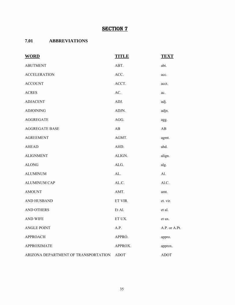
35
SECTION 7 7.01 ABBREVIATIONS WORD TITLE TEXT ABUTMENT ABT. abt. ACCELERATION ACC. acc. ACCOUNT ACCT. acct. ACRES AC. ac. ADJACENT ADJ. adj. ADJOINING ADJN. adjn. AGGREGATE AGG. agg. AGGREGATE BASE AB AB AGREEMENT AGMT. agmt. AHEAD AHD. ahd. ALIGNMENT ALIGN. align. ALONG ALG. alg. ALUMINUM AL. Al. ALUMINUM CAP AL.C. Al.C. AMOUNT AMT. amt. AND HUSBAND ET VIR. et. vir. AND OTHERS Et Al. et al. AND WIFE ET UX. et ux. ANGLE POINT A.P. A.P. or A.Pt. APPROACH APPRO. appro. APPROXIMATE APPROX. approx. ARIZONA DEPARTMENT OF TRANSPORTATION ADOT ADOT
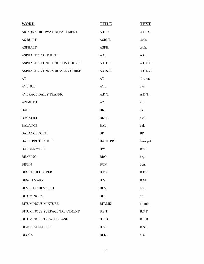
36
WORD TITLE TEXT ARIZONA HIGHWAY DEPARTMENT A.H.D. A.H.D. AS BUILT ASBLT. asblt. ASPHALT ASPH. asph. ASPHALTIC CONCRETE A.C. A.C. ASPHALTIC CONC. FRICTION COURSE A.C.F.C. A.C.F.C. ASPHALTIC CONC. SURFACE COURSE A.C.S.C. A.C.S.C. AT AT @ or at AVENUE AVE. ave. AVERAGE DAILY TRAFFIC A.D.T. A.D.T. AZIMUTH AZ. az. BACK BK. bk. BACKFILL BKFL. bkfl. BALANCE BAL. bal. BALANCE POINT BP BP BANK PROTECTION BANK PRT. bank prt. BARBED WIRE BW BW BEARING BRG. brg. BEGIN BGN. bgn. BEGIN FULL SUPER B.F.S. B.F.S. BENCH MARK B.M. B.M. BEVEL OR BEVELED BEV. bev. BITUMINOUS BIT. bit. BITUMINOUS MIXTURE BIT.MIX bit.mix BITUMINOUS SURFACE TREATMENT B.S.T. B.S.T. BITUMINOUS TREATED BASE B.T.B. B.T.B. BLACK STEEL PIPE B.S.P. B.S.P. BLOCK BLK. blk.

37
WORD TITLE TEXT BORROW BOR. bor. BOTTOM OF DECK B.D. B.D. BOULEVARD BLVD. blvd. BOUNDED BDED. bded. BOUNDARY BNDRY. bndry. BRASS CAP B.C. B.C. BRIDGE BR. br. BUILDING BLDG. bldg. BUREAU OF PUBLIC ROADS B.P.R. B.P.R. (or) U.S.B.P.R. (or) U.S.B.P.R. CALCULATED CALC. calc. CALCULATED COURSE (BEARING) C.C. C.C. CAST IN PLACE C-I-P C-I-P CAST IRON C.I. C.I. CAST IRON PIPE C.I.P. C.I.P. CATCH BASIN C.B. C.B. CATTLE GUARD C.G. C.G. CATTLE PASS C. PASS C. Pass CEMENT CEMT. cemt. CEMENT TREATED BASE C.T.B. C.T.B. CEMETERY CEM. cem. CENTER CTR. ctr. CENTER LINE CL or C/L CL or C/L CENTER TO CENTER C. to C. C. to C. CHAIN LINK C. L. C. L. CHAINS CHS. chs. CHANNEL CHAN. chan.
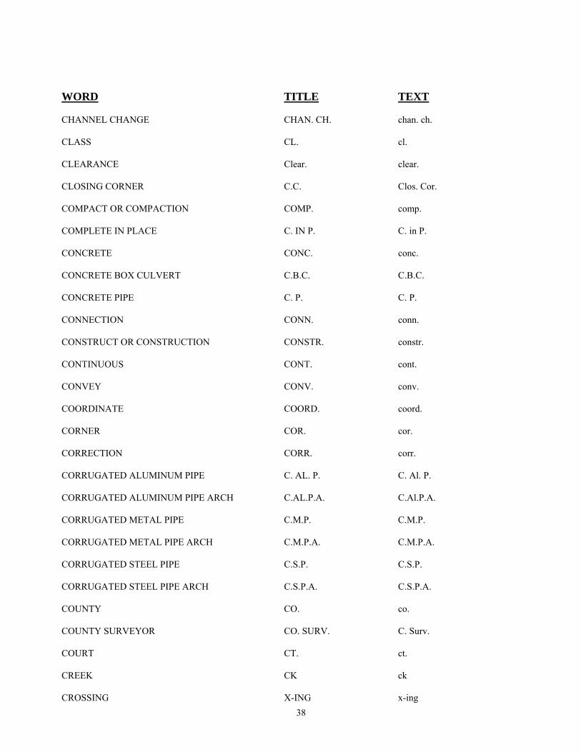
38
WORD TITLE TEXT CHANNEL CHANGE CHAN. CH. chan. ch. CLASS CL. cl. CLEARANCE Clear. clear. CLOSING CORNER C.C. Clos. Cor. COMPACT OR COMPACTION COMP. comp. COMPLETE IN PLACE C. IN P. C. in P. CONCRETE CONC. conc. CONCRETE BOX CULVERT C.B.C. C.B.C. CONCRETE PIPE C. P. C. P. CONNECTION CONN. conn. CONSTRUCT OR CONSTRUCTION CONSTR. constr. CONTINUOUS CONT. cont. CONVEY CONV. conv. COORDINATE COORD. coord. CORNER COR. cor. CORRECTION CORR. corr. CORRUGATED ALUMINUM PIPE C. AL. P. C. Al. P. CORRUGATED ALUMINUM PIPE ARCH C.AL.P.A. C.Al.P.A. CORRUGATED METAL PIPE C.M.P. C.M.P. CORRUGATED METAL PIPE ARCH C.M.P.A. C.M.P.A. CORRUGATED STEEL PIPE C.S.P. C.S.P. CORRUGATED STEEL PIPE ARCH C.S.P.A. C.S.P.A. COUNTY CO. co. COUNTY SURVEYOR CO. SURV. C. Surv. COURT CT. ct. CREEK CK ck CROSSING X-ING x-ing

39
WORD TITLE TEXT CROSS SECTION X-SEC. X-sec. CROWN CR. cr. CUBIC CU. cu. CUBIC FEET PER SECOND C.F.S. C.F.S. CUBIC YARD C.Y. c.y. CULVERT CULV. culv. CURB & GUTTER C. & G. C. & G. CURVE TO SPIRAL C.S. C.S. DECELERATION DECEL. decel. DECLINATION DECL. decl. DEDICATED DED. ded. DEFLECTION DEFL. defl. DEFLECTION OF TOTAL CURVE I or ∆ I or ∆ (OR CURVE WITH SPIRAL) DEGREE OF CURVE D. D. DELINEATOR DEL. del. DELTA ∆ ∆ DELTA ALPHA ∆α ∆α DEPARTMENT DEPT. dept. DEPARTURE DEP. or X or E dep. or X or E DEPRESSED CURB D.C. D.C. DESCRIBE DESC. desc. DETAIL DTL. dtl. DETOUR DET. det. DIAMETER DIA. dia. DIKE DK. dk. DIMENSION DIM. dim.
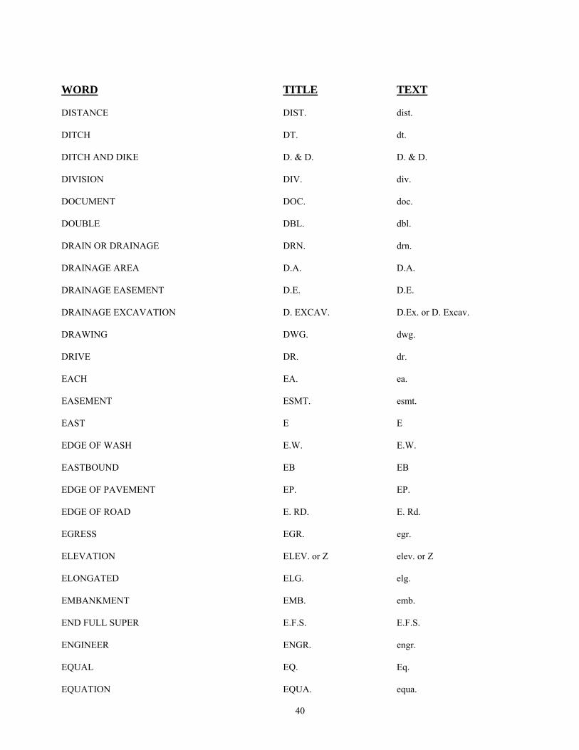
40
WORD TITLE TEXT DISTANCE DIST. dist. DITCH DT. dt. DITCH AND DIKE D. & D. D. & D. DIVISION DIV. div. DOCUMENT DOC. doc. DOUBLE DBL. dbl. DRAIN OR DRAINAGE DRN. drn. DRAINAGE AREA D.A. D.A. DRAINAGE EASEMENT D.E. D.E. DRAINAGE EXCAVATION D. EXCAV. D.Ex. or D. Excav. DRAWING DWG. dwg. DRIVE DR. dr. EACH EA. ea. EASEMENT ESMT. esmt. EAST E E EDGE OF WASH E.W. E.W. EASTBOUND EB EB EDGE OF PAVEMENT EP. EP. EDGE OF ROAD E. RD. E. Rd. EGRESS EGR. egr. ELEVATION ELEV. or Z elev. or Z ELONGATED ELG. elg. EMBANKMENT EMB. emb. END FULL SUPER E.F.S. E.F.S. ENGINEER ENGR. engr. EQUAL EQ. Eq. EQUATION EQUA. equa.

41
WORD TITLE TEXT ESTIMATE EST. est. EXCAVATION EXCAV. excav. EXISTING EXIST. exist. EXTEND OR EXTENSION EXTD. extd. EXTERNAL DISTANCE EXT. ext. FEDERAL FED. fed. FEET OR FOOT FT. ft. FENCE FE. fe. FIGURE FG. fg. FINISH FN. fn. FIRE HYDRANT F.H. F.H. FLOOR FL. fl. FLOWAGE EASEMENT FE FE FLOW LINE F.L. F.L. FOREST FST. fst. FOUND FND. fnd. FRAME FR. fr. FREEWAY FRWY. frwy. FRONTAGE FRT. frt. FURNISH OR FURNISHED FURN. furn. FUTURE FUT. fut. GALVANIZE OR GALVANIZED GALV. galv. GAS METER G.M. G.M. GAS VALVE G.V. G.V. GAUGE GA. ga. GILA AND SALT RIVER MERIDIAN G.&S.R.M. G.&S.R.M. GOVERNMENT GOVT. govt.
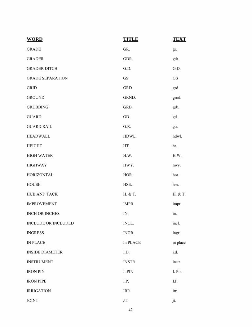
42
WORD TITLE TEXT GRADE GR. gr. GRADER GDR. gdr. GRADER DITCH G.D. G.D. GRADE SEPARATION GS GS GRID GRD grd GROUND GRND. grnd. GRUBBING GRB. grb. GUARD GD. gd. GUARD RAIL G.R. g.r. HEADWALL HDWL. hdwl. HEIGHT HT. ht. HIGH WATER H.W. H.W. HIGHWAY HWY. hwy. HORIZONTAL HOR. hor. HOUSE HSE. hse. HUB AND TACK H. & T. H. & T. IMPROVEMENT IMPR. impr. INCH OR INCHES IN. in. INCLUDE OR INCLUDED INCL. incl. INGRESS INGR. ingr. IN PLACE In PLACE in place INSIDE DIAMETER I.D. i.d. INSTRUMENT INSTR. instr. IRON PIN I. PIN I. Pin IRON PIPE I.P. I.P. IRRIGATION IRR. irr. JOINT JT. jt.
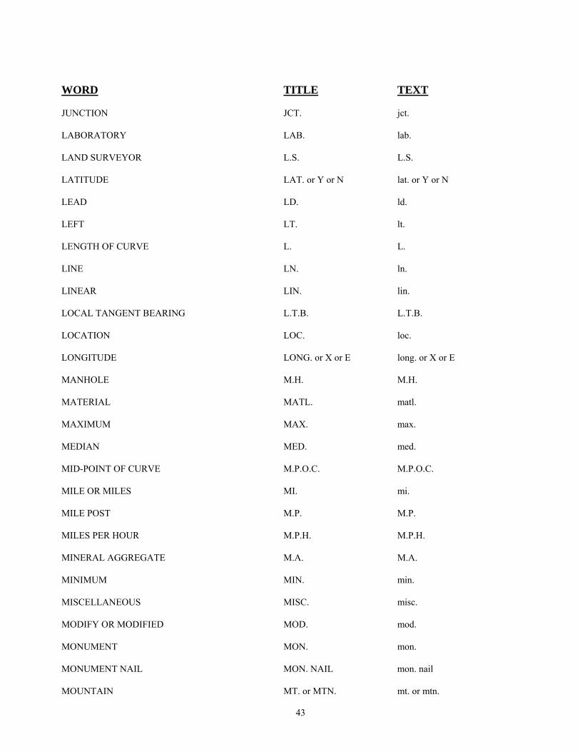
43
WORD TITLE TEXT JUNCTION JCT. jct. LABORATORY LAB. lab. LAND SURVEYOR L.S. L.S. LATITUDE LAT. or Y or N lat. or Y or N LEAD LD. ld. LEFT LT. lt. LENGTH OF CURVE L. L. LINE LN. ln. LINEAR LIN. lin. LOCAL TANGENT BEARING L.T.B. L.T.B. LOCATION LOC. loc. LONGITUDE LONG. or X or E long. or X or E MANHOLE M.H. M.H. MATERIAL MATL. matl. MAXIMUM MAX. max. MEDIAN MED. med. MID-POINT OF CURVE M.P.O.C. M.P.O.C. MILE OR MILES MI. mi. MILE POST M.P. M.P. MILES PER HOUR M.P.H. M.P.H. MINERAL AGGREGATE M.A. M.A. MINIMUM MIN. min. MISCELLANEOUS MISC. misc. MODIFY OR MODIFIED MOD. mod. MONUMENT MON. mon. MONUMENT NAIL MON. NAIL mon. nail MOUNTAIN MT. or MTN. mt. or mtn.
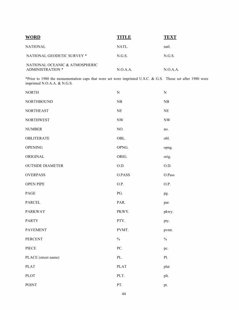
44
WORD TITLE TEXT NATIONAL NATL. natl. NATIONAL GEODETIC SURVEY * N.G.S. N.G.S. NATIONAL OCEANIC & ATMOSPHERIC ADMINISTRATION * N.O.A.A. N.O.A.A. *Prior to 1980 the monumentation caps that were set were imprinted U.S.C. & G.S. Those set after 1980 were imprinted N.O.A.A. & N.G.S. NORTH N N NORTHBOUND NB NB NORTHEAST NE NE NORTHWEST NW NW NUMBER NO. no. OBLITERATE OBL. obl. OPENING OPNG. opng. ORIGINAL ORIG. orig. OUTSIDE DIAMETER O.D. O.D. OVERPASS O.PASS O.Pass OPEN PIPE O.P. O.P. PAGE PG. pg. PARCEL PAR. par. PARKWAY PKWY. pkwy. PARTY PTY. pty. PAVEMENT PVMT. pvmt. PERCENT % % PIECE PC. pc. PLACE (street name) PL. Pl. PLAT PLAT plat PLOT PLT. plt. POINT PT. pt.
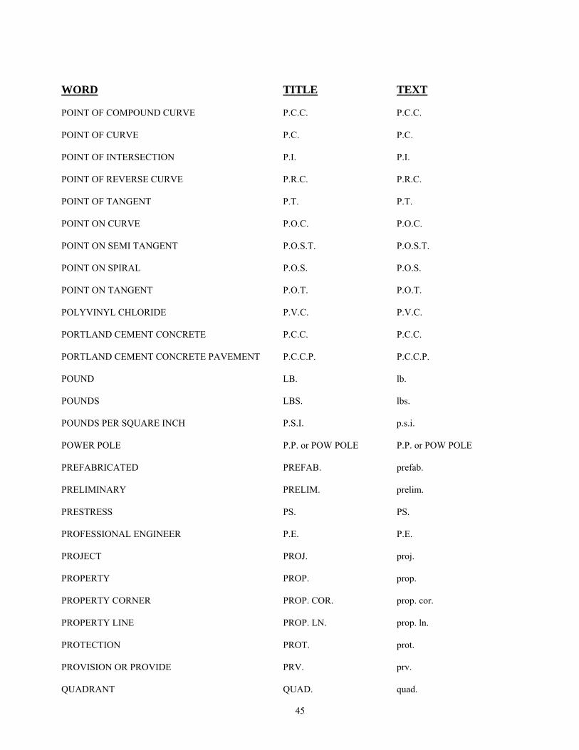
45
WORD TITLE TEXT POINT OF COMPOUND CURVE P.C.C. P.C.C. POINT OF CURVE P.C. P.C. POINT OF INTERSECTION P.I. P.I. POINT OF REVERSE CURVE P.R.C. P.R.C. POINT OF TANGENT P.T. P.T. POINT ON CURVE P.O.C. P.O.C. POINT ON SEMI TANGENT P.O.S.T. P.O.S.T. POINT ON SPIRAL P.O.S. P.O.S. POINT ON TANGENT P.O.T. P.O.T. POLYVINYL CHLORIDE P.V.C. P.V.C. PORTLAND CEMENT CONCRETE P.C.C. P.C.C. PORTLAND CEMENT CONCRETE PAVEMENT P.C.C.P. P.C.C.P. POUND LB. lb. POUNDS LBS. lbs. POUNDS PER SQUARE INCH P.S.I. p.s.i. POWER POLE P.P. or POW POLE P.P. or POW POLE PREFABRICATED PREFAB. prefab. PRELIMINARY PRELIM. prelim. PRESTRESS PS. PS. PROFESSIONAL ENGINEER P.E. P.E. PROJECT PROJ. proj. PROPERTY PROP. prop. PROPERTY CORNER PROP. COR. prop. cor. PROPERTY LINE PROP. LN. prop. ln. PROTECTION PROT. prot. PROVISION OR PROVIDE PRV. prv. QUADRANT QUAD. quad.

46
WORD TITLE TEXT QUARTER 1/4 1/4 QUANTITY QUAN. quan. QUANTITY OF DRAINAGE RUNOFF Q Q RADIUS R. R. RAILROAD R.R. or R/R R.R. or R/R RAILWAY RY. Ry. RANGE R. R. RECONSTRUCT RECST. recst. RECORD REC. rec. REFERENCE REF. ref. REINFORCED OR REINFORCING REINF. reinf. REINFORCED CONCRETE R.C. R.C. REINFORCED CONCRETE PIPE R.C.P. R.C.P. REINFORCED CONCRETE PIPE ARCH R.C.P.A. R.C.P.A. REINFORCED CONCRETE PIPERUBBER GASKETED R.C.P.R.G. R.C.P.R.G. REINFORCING BAR REBAR. rebar. RELOCATE RELOC. reloc. REQUIRED REQD. reqd. RESERVATION RESVN. resvn. RESIDENCE RES. res. RETAIN OR RETAINING RET. ret. REVISED OR REVISION REV. rev. RIGHT RT. rt. RIGHT OF WAY R/W R/W RIPRAP RIPRAP riprap ROAD RD. rd.
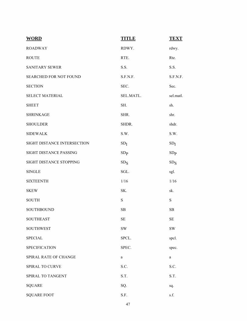
47
WORD TITLE TEXT ROADWAY RDWY. rdwy. ROUTE RTE. Rte. SANITARY SEWER S.S. S.S. SEARCHED FOR NOT FOUND S.F.N.F. S.F.N.F. SECTION SEC. Sec. SELECT MATERIAL SEL.MATL. sel.matl. SHEET SH. sh. SHRINKAGE SHR. shr. SHOULDER SHDR. shdr. SIDEWALK S.W. S.W. SIGHT DISTANCE INTERSECTION SDI SDI SIGHT DISTANCE PASSING SDP SDP SIGHT DISTANCE STOPPING SDS SDS SINGLE SGL. sgl. SIXTEENTH 1/16 1/16 SKEW SK. sk. SOUTH S S SOUTHBOUND SB SB SOUTHEAST SE SE SOUTHWEST SW SW SPECIAL SPCL. spcl. SPECIFICATION SPEC. spec. SPIRAL RATE OF CHANGE a a SPIRAL TO CURVE S.C. S.C. SPIRAL TO TANGENT S.T. S.T. SQUARE SQ. sq. SQUARE FOOT S.F. s.f.
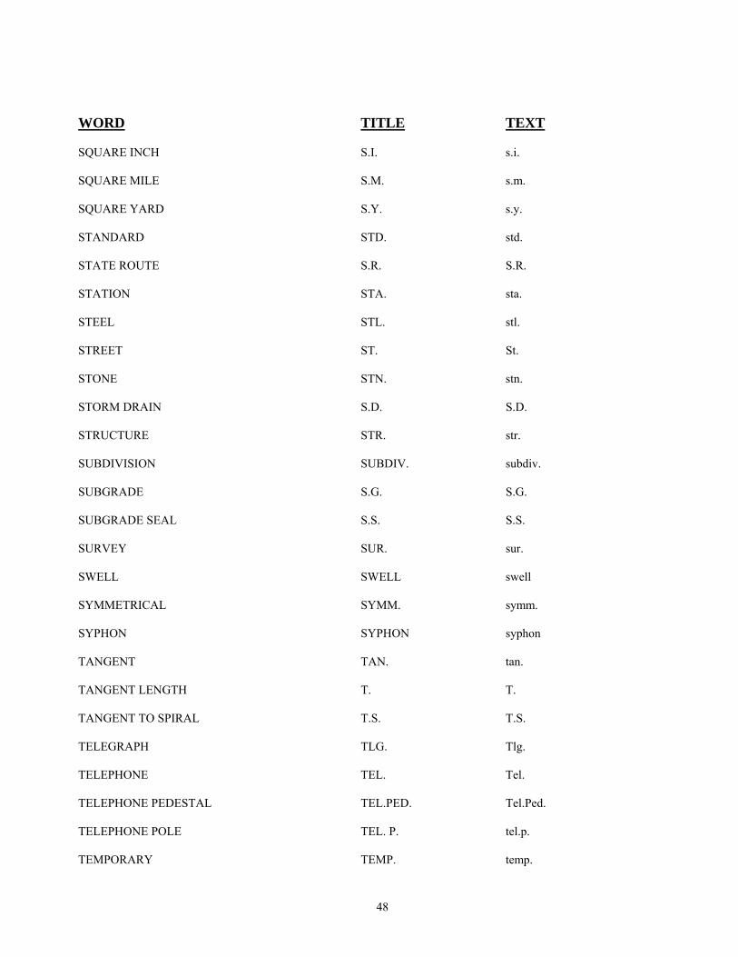
48
WORD TITLE TEXT SQUARE INCH S.I. s.i. SQUARE MILE S.M. s.m. SQUARE YARD S.Y. s.y. STANDARD STD. std. STATE ROUTE S.R. S.R. STATION STA. sta. STEEL STL. stl. STREET ST. St. STONE STN. stn. STORM DRAIN S.D. S.D. STRUCTURE STR. str. SUBDIVISION SUBDIV. subdiv. SUBGRADE S.G. S.G. SUBGRADE SEAL S.S. S.S. SURVEY SUR. sur. SWELL SWELL swell SYMMETRICAL SYMM. symm. SYPHON SYPHON syphon TANGENT TAN. tan. TANGENT LENGTH T. T. TANGENT TO SPIRAL T.S. T.S. TELEGRAPH TLG. Tlg. TELEPHONE TEL. Tel. TELEPHONE PEDESTAL TEL.PED. Tel.Ped. TELEPHONE POLE TEL. P. tel.p. TEMPORARY TEMP. temp.
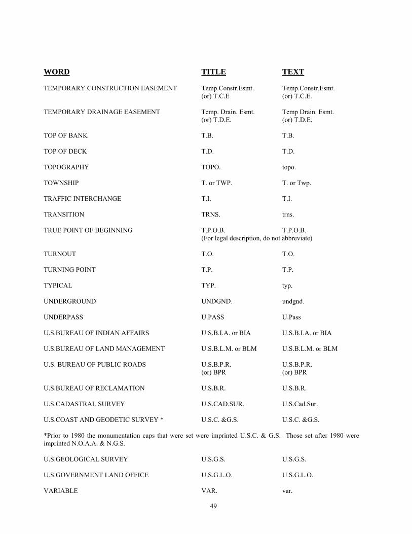
49
WORD TITLE TEXT TEMPORARY CONSTRUCTION EASEMENT Temp.Constr.Esmt. Temp.Constr.Esmt. (or) T.C.E (or) T.C.E. TEMPORARY DRAINAGE EASEMENT Temp. Drain. Esmt. Temp Drain. Esmt. (or) T.D.E. (or) T.D.E. TOP OF BANK T.B. T.B. TOP OF DECK T.D. T.D. TOPOGRAPHY TOPO. topo. TOWNSHIP T. or TWP. T. or Twp. TRAFFIC INTERCHANGE T.I. T.I. TRANSITION TRNS. trns. TRUE POINT OF BEGINNING T.P.O.B. T.P.O.B. (For legal description, do not abbreviate) TURNOUT T.O. T.O. TURNING POINT T.P. T.P. TYPICAL TYP. typ. UNDERGROUND UNDGND. undgnd. UNDERPASS U.PASS U.Pass U.S.BUREAU OF INDIAN AFFAIRS U.S.B.I.A. or BIA U.S.B.I.A. or BIA U.S.BUREAU OF LAND MANAGEMENT U.S.B.L.M. or BLM U.S.B.L.M. or BLM U.S. BUREAU OF PUBLIC ROADS U.S.B.P.R. U.S.B.P.R. (or) BPR (or) BPR U.S.BUREAU OF RECLAMATION U.S.B.R. U.S.B.R. U.S.CADASTRAL SURVEY U.S.CAD.SUR. U.S.Cad.Sur. U.S.COAST AND GEODETIC SURVEY * U.S.C. &G.S. U.S.C. &G.S. *Prior to 1980 the monumentation caps that were set were imprinted U.S.C. & G.S. Those set after 1980 were imprinted N.O.A.A. & N.G.S. U.S.GEOLOGICAL SURVEY U.S.G.S. U.S.G.S. U.S.GOVERNMENT LAND OFFICE U.S.G.L.O. U.S.G.L.O. VARIABLE VAR. var.
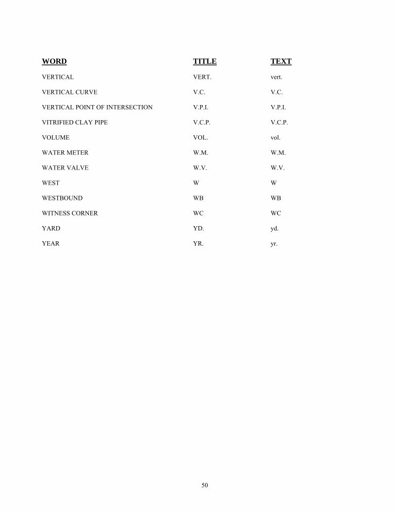
50
WORD TITLE TEXT VERTICAL VERT. vert. VERTICAL CURVE V.C. V.C. VERTICAL POINT OF INTERSECTION V.P.I. V.P.I. VITRIFIED CLAY PIPE V.C.P. V.C.P. VOLUME VOL. vol. WATER METER W.M. W.M. WATER VALVE W.V. W.V. WEST W W WESTBOUND WB WB WITNESS CORNER WC WC YARD YD. yd. YEAR YR. yr.