section 03 01 00 concrete repairs part 1. general - sagres construction · 2017-10-11 · section...
TRANSCRIPT

DC WATER CONCRETE REPAIRS IFB # 160020 – SMALL DIAMETER WATER MAIN REPLACEMENT 13A 03 01 00 - 1 SEPTEMBER 17, 2017
SECTION 03 01 00
CONCRETE REPAIRS
PART 1. GENERAL
1.1 SUMMARY:
A. Preparation of concrete and application of repair materials. B. Rehabilitation and restoration of concrete surfaces. C. Repair of concrete internal reinforcement.
1.2 RELATED DOCUMENTS:
A. Drawings, Technical Specification Sections, General and Supplementary Conditions of the Contract and other Division 00 and Division 01 Specification Sections, apply to this Section.
B. Specifications throughout all Divisions of the Project Manual are directly pertinent to this Section, and this Section is directly pertinent to them.
1.3 RELATED SECTIONS: Specified elsewhere may include but are not limited to:
A. Section 01 66 10: Product Delivery, Storage and Handling Requirements B. Section 01 33 00: Submittals C. Section 01 43 00: Quality Requirements D. Section 01 45 29: Testing Laboratory Services E. Section 01 78 39: Project Record Documents F. Section 03 20 00: Reinforcing Steel Rebars G. Section 03 22 00: Welded Wire Reinforcement
1.4 REFERENCE CODES:
A. American Society of Testing and Materials (ASTM): 1. ASTM A615: “Standard Specification for Deformed and Plain Carbon-Steel Bars
for Concrete Reinforcement”. 2. ASTM A996: “Standard Specification for Rail-Steel and Axle Steel Deformed
Bars for Concrete Reinforcement”. 3. ASTM A1064: “Standard Specifications for Steel Wire Welded Wire
Reinforcement, Plain and Deformed, for Concrete. 4. ASTM C33: “Standard Specification for Concrete Aggregates”. 5. ASTM C150: “Standard Specification for Portland Cement”. 6. ASTM C404: “Standard Specification for Aggregates for Masonry Grout”. 7. ASTM C882: “Standard Test Method for Bond Strength of Epoxy Resin Systems
Used with Concrete By Slant Shear”. 8. ASTM D638: “Standard Test Method for Tensile Properties of Plastics”. 9. ASTM D695: “Standard Test Method for Compressive Properties of Rigid
Plastics”. 10. ASTM D790: “Standard Test Methods for Flexural Properties of Unreinforced
and Reinforced Plastics and Electrical Insulating Materials”. B. American Welding Society (AWS):
1. AWS D1.4: “Structural Welding Code for Reinforcing Steel”.
1.5 SUBMITTALS:
A. Requirements for “Submittals” shall be in accordance to Section 01 33 00.

DC WATER CONCRETE REPAIRS IFB # 160020 – SMALL DIAMETER WATER MAIN REPLACEMENT 13A 03 01 00 - 2 SEPTEMBER 17, 2017
B. Submit certified “Design Mix”. Design Mix shall be approved by the jurisdiction DOT where the project is being performed. Include a copy of the approved Design Mix Certification.
C. Submit the “Product Data Sheets” indicating product standards, physical and chemical characteristics, technical specifications, limitations, maintenance instructions, and general recommendations regarding each material used.
D. Submit a proposed list of sources of all material. Sources shall be approved by the jurisdiction DOT where the project is being performed and shall include a copy of their certification of each source.
E. Submit the “Installation Instructions and Details” describing and showing how the Concrete Repair material will be installed.
F. Submit the “Test Results” of each product used. G. Submit the “Field Inspection Data” for Concrete Repairs.
1.6 PROJECT RECORD DOCUMENTS:
A. Requirements for ‘Project Record Documents” shall be in accordance to Section 01 78 39 and submit the required materials used for the project.
B. Accurately record actual locations of structural reinforcement repairs, type of repair.
1.7 PRODUCT DELIVERY, STORAGE, AND HANDLING REQUIREMENTS:
A. Requirements for “Product Delivery, Storage, and Handling Requirements” shall be in accordance to Section 01 66 10.
B. Comply with instructions for storage, shelf life limitations, and handling.
PART 2. PRODUCTS
2.1 PATCHING MATERIALS:
A. Epoxy Resin: Two part epoxy adhesive containing 100 % percent solids, meeting the following minimum characteristics:
Characteristic Test Method Results
Bond Strength ANSI/ASTM C882 2,700 psi
Tensile Strength ASTM D638 6,600 psi
Elongation ASTM D638 2 % percent
at 7 days at 70 degrees F
Flexural Strength ASTM D790 8,000 psi
Compressive Strength ASTM D695 6,500 psi B. Bonding Agent: Polyvinyl acetate emulsion, dispersed in water while mixing non-
coagulant in mix, water resistant when cured. C. Portland Cement: ASTM C150, Type II D. Sand: [ASTM C33;] [ANSI/ASTM C404;] uniformly graded, clean. E. Water: Clean and potable. F. Cleaning Agent: Commercial muriatic acid.
2.2 REINFORCEMENT MATERIALS:
A. Requirements for “Reinforcing Steel Rebars” shall be in accordance to Section 03 20 00. B. Reinforcing Steel: ASTM A996; 60 ksi yield grade axle steel deformed bars, galvanized
finish. C. Requirements for “Welded Wire Reinforcement” shall be in accordance to Section 03 22
00 and ASTM A1064. D. Requirements for “Deformed and Plain Carbon-Steel Bars for Concrete Reinforcement
shall be in accordance to ASTM A615.

DC WATER CONCRETE REPAIRS IFB # 160020 – SMALL DIAMETER WATER MAIN REPLACEMENT 13A 03 01 00 - 3 SEPTEMBER 17, 2017
2.3 MIXING EPOXY MORTARS:
A. Mix epoxy mortars in accordance with manufacturer's instructions for purpose intended. B. Mix components in clean equipment or containers. Conform to pot life and workability
limits.
2.4 MIXING CEMENTITIOUS MATERIALS:
A. Mix cementations mortar and/or grout in accordance with manufacturer's instructions for purpose intended.
B. Bonding agent as additive to mix in accordance with manufacturer's instructions.
PART 3. EXECUTION
3.1 EXAMINATION:
A. Verify that surfaces are ready to receive work. B. Beginning of installation means installer accepts existing surfaces and/or substrate.
3.2 PREPARATION:
A. Clean concrete surfaces of dirt, laitance, corrosion, or other contamination; wire brush using water and/or acid. Rinse surface and allow too dry.
B. Flush out cracks and voids with muriatic acid to remove laitance and dirt. Chemically neutralize by rinsing with water.
C. Provide temporary entry ports spaced to accomplish movement of fluids between ports, no deeper than the depth of the crack to be filled. Limit port size diameter to be no greater than the thickness of the crack. Provide temporary seal at concrete surface to prevent leakage of adhesive.
D. For areas patched with epoxy mortar, remove broken and soft concrete 1/4 inch deep. Remove corrosion from steel. Clean surfaces mechanically; wash with acid and rinse with water.
E. Sandblast: clean the exposed reinforcement steel surfaces. Mechanically cut away damaged portions of bar.
3.3 REPAIR WORK:
A. Repair exposed structural, shrinkage, and settlement cracks of concrete by the [epoxy injection] and/or [bonding agent and cementitious paste] method.
B. [Repair Spalling.]: [Fill voids flush with surface.] [Apply surface finish.] C. Repair reinforcement by welding new bar reinforcement to existing reinforcement with
sleeve splices. Contractor shall strength of welded splices and reinforcement shall exceed original stress values.
3.4 INJECTION OF EPOXY RESIN ADHESIVE:
A. Inject adhesive into prepared ports under pressure using equipment appropriate for particular application.
B. Begin injection at lower entry port and continue until adhesive appears in adjacent entry port. Continue from port to port until entire crack is filled.
C. Remove temporary seal and excessive adhesive. D. Clean surfaces adjacent to repair and blend finish.
3.5 APPLICATION EPOXY MORTAR:
A. Trowel apply mortar mix to an average thickness of 1/2 inches. Tamp into place filling voids at spalled areas.
B. For patching honeycomb, trowel mortar onto surface, working into honeycomb to bring surface flush with surrounding area. Finish trowel surface to match surrounding area.
C. Cover exposed steel reinforcement with epoxy mortar; feather edges to flush surface.
DC WATER CONCRETE REPAIRS IFB # 160020 – SMALL DIAMETER WATER MAIN REPLACEMENT 13A 03 01 00 - 4 SEPTEMBER 17, 2017
3.6 APPLICATION OF CEMENTITIOUS [MORTAR] AND/OR [GROUT]:
A. Apply coating of bonding agent to concrete surfaces and provide full surface coverage in accordance with manufacturer's instructions.
B. Apply cementitious [mortar] and/or [grout] by steel trowel to an average thickness of 1/2 inches. Tamp into place filling voids at spalled areas. Work mix into honeycomb.
C. Damp cure cementitious [mortar] and/or [grout] in accordance with manufacturer's instructions
3.7 FIELD QUALITY CONTROL:
A. Requirements for “Quality Requirements” shall be in accordance to Section 01 43 00. B. Requirements for “Testing Laboratory Services” shall be in accordance to Section 01 45
29. C. Conduct field inspection and test concrete for calcium chloride and/or any other chemical
content which can affect the properties and execution of the Work.
PART 4. MEASUREMENT AND PAYMENT
4.1 CONCRETE REPAIRS:
A. Measurement: 1. Work for Concrete Repairs will not be measured separately for payment.
B. Payment: 1. No separate payment will be made for work under this Section. Payment for
Concrete Repairs shall be considered incidental and included under the item of which it is a part of in the SOP’s, which price and payment shall include but not be limited to minor complications and/or delays, traffic maintenance and protection and all labor, materials, tools, fees and equipment necessary to complete the work as specified within this Contract.
~ END OF SECTION 03 01 00 ~

DC WATER CONCRETE FORMWORK IFB # 160020 – SMALL DIAMETER WATER MAIN REPLACEMENT 13A 03 10 00 - 1 SEPTEMBER 17, 2017
SECTION 03 10 00
CONCRETE FORMWORK
PART 1. GENERAL
1.1 SUMMARY:
A. Furnish all labor, materials, equipment and incidentals required to provide formwork for all concrete structures as shown on the Contract Drawings and as specified herein.
1.2 RELATED DOCUMENTS:
A. Drawings, Technical Specification Sections, General and Supplementary Conditions of the Contract and other Division 00 and Division 01 Specification Sections, apply to this Section.
B. Specifications throughout all Divisions of the Project Manual are directly pertinent to this Section, and this Section is directly pertinent to them.
1.3 RELATED SECTIONS: Specified elsewhere may include but are not limited to:
A. Section 01 33 00: Submittals
B. Section 03 15 13: Waterstops
C. Section 03 30 00: Cast-In-Place Concrete
1.4 REFERENCE CODES:
A. American Concrete Institute (ACI):
1. ACI 347R: "Guide to Formwork for Concrete".
2. ACI Special Publication Number SP-4: "Formwork for Concrete".
3. ACI 117: "Standard Specification for Tolerances for Concrete Construction and Materials".
4. ACI 318: “Building Code Requirements for Structural Concrete and Commentary”.
B. U. S. Commercial Standard CS-251.
C. U. S. Product Standard PS-1.
D. District of Columbia Building Code.
1.5 SUBMITTALS:
A. Requirements for “Submittals” shall be in accordance to Section 01 33 00. Submit the following:
B. Submit complete design “Calculations” for Concrete Formwork, which will be used on the project. Submit design analyses and calculations, to support Working Drawings and early removal process (if required); signed and sealed by a Licensed Professional Engineer experienced in Structural Engineering and registered in governmental jurisdiction of the project.
C. Submit the “Installation Instructions and Details” describing and showing how the Concrete Formwork will be installed.
D. Submit certified “Working Drawings” showing the proposed layout and the dimensional details for Concrete Formwork which will be used on the project. Working Drawings shall be signed and sealed by a Licensed Professional Engineer experienced in Structural Engineering and registered in governmental jurisdiction of the project.
PART 2. PRODUCTS
2.1 MATERIALS:
A. Wood Forms:

DC WATER CONCRETE FORMWORK IFB # 160020 – SMALL DIAMETER WATER MAIN REPLACEMENT 13A 03 10 00 - 2 SEPTEMBER 17, 2017
1. All framing lumber stress-graded.
2. Lumber in direct contact with concrete, dressed on at least the contact side, with dressed or tongue-and-groove edges; other lumber may be dressed or rough.
B. Plywood Forms:
1. Grade marked.
2. B-B Plyform, Exterior Class 1 and 2 and HDO High Density Concrete Form Plywood, Class 1 and 2 per U.S. Product Standard PS-1. Use at locations as specified.
C. Hardboard:
1. Tempered, smooth one-side, not less than 3/16 inch thick per U.S. Commercial Standard CS-251.
D. Form Ties:
1. Factory fabricated snap-off metal type of adequate design to minimize form deflection and preclude concrete spalling upon removal.
2. Fabricate so the setback in the concrete is such that the portion of the tie remaining after snap-off and removal of the exterior portions is at least 1-1/2 inches back from the concrete surface.
E. Bond Breaker:
1. Non-staining liquid product which imparts a waterproof film to prevent adhesion of concrete and will not leave a paint impeding coating on face of concrete.
PART 3. EXECUTION
3.1 INSTALLATION:
A. General: 1. Building Code Requirements for Structural Concrete shall be in accordance to
ACI 318; and the District of Columbia Building Code. 2. Guide for "Formwork for Concrete" will be in accordance to ACI Special
Publication Number SP-4. 3. The insides of forms shall be thoroughly cleaned prior to concreting so they are
free from dirt, debris, and any foreign material. 4. Construct adequately braced formwork so that resulting concrete surfaces will
conform to specified tolerances. 5. Brace forms, falsework, and centering adequately to retain forms in position as
shown on approved working drawings. 6. Provide mortar-tight forms of approved materials, which conform to required
shapes, lines, and dimensions and will produce a smooth surface without fins and projections.
7. Where shown on Drawings or required by the DC Water because of lagging or form irregularity, line the inner form surfaces with hardboard. Fasten securely to the backing by flush driven galvanized or aluminum nails. Line areas less than four feet wide with a single width piece of hardboard. Offset lining joints from those in the backing.
B. General Design Criteria: 1. Contractor shall design formwork for total design loads including dead and live
loads along with vertical loads and lateral pressures per ACI 347R. 2. Design formwork system, which is adequately braced and has adequate strength
and stability to ensure, finished concrete within specified tolerances. Design and engineering of the formwork and safety consideration during construction shall be the responsibility of the Contractor.
DC WATER CONCRETE FORMWORK IFB # 160020 – SMALL DIAMETER WATER MAIN REPLACEMENT 13A 03 10 00 - 3 SEPTEMBER 17, 2017
3. When necessary to maintain specified tolerances, design camber into formwork to compensate for anticipated deflection and creep due to weight and pressure of fresh concrete.
4. Chamfer exposed external corners 3/4-inch. 5. Concrete formwork drawings and calculations shall be prepared by or under the
direction of a Registered District of Columbia Professional Engineer (P.E.), and shall bear his/her P.E. Seal. Forms shall be designed in accordance with the criteria specified herein.
C. Field Quality Control:
1. Construct concrete elements to meet allowable tolerances as specified under ACI 117.
D. Coating Forms:
1. Coat forms with bond breaker prior to the placement of reinforcing steel.
2. Do not allow excess coating materials to stand in puddles in the forms nor to come in contact with concrete against which fresh concrete is to be placed.
3. Coat bolts and rods that are to be completely removed or that are to be free to move with bond breaker.
E. Embedded Items:
1. For items to be embedded in concrete, clean free from oil or foreign matter that would weaken the bond of the concrete to these items.
2. Install in the formwork requisite inserts, anchors, sleeves, and other items specified under other sections of these Specifications. Close ends of conduits, piping, and sleeves embedded in concrete with caps or plugs.
3. Concrete pads, curbs, pedestals and similar means devised by the Contractor to support the forms will be subject to review by the DC Water.
4. Before depositing concrete, check the location and support of items, which are to be wholly or partially embedded.
F. Openings and Recesses in Concrete:
1. Provide openings and recesses in the concrete as may be required and furnished by other sections of these Specifications.
G. Joints:
1. Requirements for make contraction, expansion, and construction joints shall be in accordance to Section 03 15 13 titled, “Waterstops” and/or as shown on the Contract Drawings.
2. Form keyways as shown on the Contract Drawings.
H. Removal of Forms, Falsework and Centering:
1. Maintain forms, falsework, and centering in place until the concrete has attained sufficient strength for the structural members to carry their own weight and any loads to which they will be subjected without deformation and without exceeding the permissible stresses.
2. Forms and supports shall not be removed without DC Water approval; however, in all cases, such removal and imposing of loads on the new work shall be at Contractor risk.
3. Concrete strength attained prior to form removal shall be determined from tests of cylinders adjacent to and under the same conditions as placed concrete, per Section 03 30 00 tiled, “Cast-in-place Concrete”.

DC WATER CONCRETE FORMWORK IFB # 160020 – SMALL DIAMETER WATER MAIN REPLACEMENT 13A 03 10 00 - 4 SEPTEMBER 17, 2017
4. Shores and falsework may be removed when such cylinders have been tested and show strength equal to or greater than 60 percent of the minimum 28 day field cylinder strength of the class of concrete being tested.
5. Except as specifically authorized, forms shall not be removed before the concrete has attained a strength of at least 30 percent of the 28 day field cylinder strength of the class of concrete affected, and not before reaching the following number of day-degrees (whichever is the longer period).
Forms For Day-Degrees*
Beams and slabs including 500 integrally poured walls Walls, piers, footings, 100 other elements
a. *Day-degree: Total number of days times average daily air temperature at surface of concrete. For example, 5 days at a daily weighted average temperature of 60 deg. F, equal 300 day-degrees. On days when temperature at the surface of the concrete is below or drops below 40 deg. F, the number of day-degrees for that day shall be zero (0).
6. Do not alter the loading conditions on the concrete subsequent to the removal of forms if it results in exceeding the permissible stresses and deformation at the attained concrete strengths.
7. The removal portion of form ties shall be withdrawn from the concrete immediately after taking down the forms. The holes left by such ties shall be filled with grout from a grout gun and the surface shall be finished with a steel spatula or rubbed with sackcloth.
8. Care shall be taken in removing forms, wales, shoring, supports, and form ties to avoid spalling or marring the concrete. The required finish and such patching as may be necessary shall be started immediately after form removal.
9. Backfilling may begin immediately after the necessary patching and finish on the concrete has hardened sufficiently so marring will not result. Heavy equipment used in backfilling shall be used with discretion and at Contractor risk.
PART 4. MEASUREMENT AND PAYMENT
4.1 CONCRETE FORMWORK:
A. Measurement: 1. Work for Concrete Formwork will not be measured separately for payment.
B. Payment: 1. No separate payment will be made for work under this Section. Payment for
Concrete Formwork shall be considered incidental and included under the item of which it is a part of in the SOP’s, which price and payment shall include but not be limited to minor complications and/or delays, traffic maintenance and protection and all labor, materials, tools, fees and equipment necessary to complete the work as specified within this Contract.
~ END OF SECTION 03 10 00 ~

DC WATER CONCRETE ANCHORING
IFB # 160020 – SMALL DIAMETER WATER MAIN REPLACEMENT 13A 03 15 00 - 1SEPTEMBER 17, 2017
SECTION 03 15 00
CONCRETE ANCHORING
PART 1. GENERAL
1.1 SUMMARY:
A. Furnish all labor, materials, equipment and incidentals required to provide post installed concrete anchoring for all concrete structures as shown on the Standard Detail Drawings and as specified herein to complete the necessary work.
1.2 RELATED DOCUMENTS:
A. Drawings, Technical Specification Sections, General and Supplementary Conditions of the Contract and other Division 00 and Division 01 Specification Sections, apply to this Section.
B. Specifications throughout all Divisions of the Project Manual are directly pertinent to this Section, and this Section is directly pertinent to them.
1.3 RELATED SECTIONS: Specified elsewhere may include but are not limited to:
A. Section 01 33 00: Submittals
1.4 REFERENCE CODES:
A. American Concrete Institute (ACI): 1. ACI 318: “Building Code Requirements for Structural Concrete and
Commentary”. 2. ACI 355.2: “Standard for Evaluating the Performance of Post-Installed
Mechanical Anchors in Concrete”. B. American Iron and Steel Institute (AISI): C. American Society of Testing and Materials (ASTM):
1. ASTM A36: “Standard Specification for Carbon Structural Steel”. 2. ASTM A153: “Standard Specification for Zinc Coating (Hot-Dip) on Iron and
Steel Hardware”. 3. ASTM A193: “Standard Specification for Alloy-Steel and Stainless Steel Bolting
Materials for High-Temperature Service”. 4. ASTM A307: “Standard Specification for Carbon Steel Bolts and Studs, 60,000
psi Tensile Strength”. 5. ASTM A615: “Standard Specification for Deformed and Plain Billet-Steel Bars
for Concrete Reinforcement”. 6. ASTM B633: “Standard Specification for Electrodeposited Coatings of Zinc on
Iron and Steel”. 7. ASTM B695: “Standard Specification for Coatings of Zinc Mechanically
Deposited on Iron and Steel”. 8. ASTM A706: “ 9. ASTM C881: “Standard Specification Epoxy-Resin-Based Bonding Systems for
Concrete”.10. ASTM E488: “Standard Test Methods for Strength of Anchors in Concrete and
Masonry Elements”. 11. ASTM E1512: “Standard Test Methods for Testing Bond Performance of
Bonded Anchors”. 12. ASTM F593: “Standard Specification for Stainless Steel Bolts, Hex Cap Screws,
and Studs”. 13. ASTM F1554: “
D. Federal Specifications A-A-1922A, A-A01923A and A-A-55614 for Expansion and Shield-Type Anchors.

DC WATER CONCRETE ANCHORING
IFB # 160020 – SMALL DIAMETER WATER MAIN REPLACEMENT 13A 03 15 00 - 2SEPTEMBER 17, 2017
E. International Code Council Evaluation Service (ICC-ES): 1. ICC-ES AC01: “Acceptance Criteria for Expansion Anchors in Masonry
Elements”. 2. ICC-ES AC58: “Acceptance Criteria for Adhesive Anchors in Masonry
Elements”. 3. ICC-ES AC60: “Acceptance Criteria for Anchors in Unreinforced Masonry
Elements”. 4. ICC-ES AC70: “Acceptance Criteria for Fasteners Power-Driven into Concrete,
Steel and Masonry Elements”. 5. ICC-ES AC106: “Acceptance Criteria for Predrilled Fasteners (Screw Anchors)
in Concrete or Masonry Elements”. 6. ICC-ES AC193: “Acceptance Criteria for Mechanical Anchors in Concrete
Elements”. 7. ICC-ES AC308: “Acceptance Criteria for Post-Installed Adhesive Anchors in
Concrete Elements”.
1.5 SUBMITTALS:
A. Requirements for “Submittals” shall be in accordance to Section 01 33 00. B. Product Data Sheet: Submit data for proprietary materials, manufacturer’s specifications
(including finishes and/or materials) Safety Data Sheets (SDS) and installation procedures.
C. Test Reports: ICC-ES listings and performance data that includes recommended loading for each application.
D. Only manufacturers with an ICC-ES listing will be considered for substitution requests.The contractor shall submit for Engineer-of-Record’s review, calculations that are prepared & sealed by a registered Professional Engineer demonstrating that the substituted product is capable of achieving the pertinent equivalent performance values of the specified product using the appropriate design procedure and/or standard(s) as required by the Building Code. In addition, the calculations shall specify the diameter and embedment depth of the substituted product. Any increase in material costs for such submittal shall be the responsibility of the Contractor.
1.6 QUALITY ASSURANCE:
A. Post-Installed anchors and related materials shall be listed by one or more of the following agencies, as applicable: 1. ICC Evaluation Service. 2. City or County of the authority having jurisdiction (DOT). 3. Underwriters Laboratories (UL) and/or Factory Mutual (FM).
1.7 DELIVERY, STORAGE, AND HANDLING:
A. Deliver products to job site in manufacturer’s or distributor’s packaging undamaged, complete with installation instructions.
B. Protect and handle materials in accordance with manufacturer’s recommendations to prevent damage or deterioration.
PART 2. PRODUCTS
2.1 CRITERIA:
A. EXPANSION ANCHORS: 1. Cracked Concrete Wedge Anchors: Anchors used to transmit load [i.) Between
structural elements and/or ii.) From life safety-related attachments] shall be designed in accordance with ACI 318 Appendix D, which requires post-installed mechanical anchors to be qualified according to ACI 355.2. Such anchors shall be an imperial sized, threaded stud with an integral cone expander and three-segment expansion clip. The stud shall be manufactured from carbon steel and the expansion clip shall have 2 undercutting embossments per segment and be
DC WATER CONCRETE ANCHORING
IFB # 160020 – SMALL DIAMETER WATER MAIN REPLACEMENT 13A 03 15 00 - 3SEPTEMBER 17, 2017
manufactured from 316 stainless steel. Carbon steel anchors shall have an electroplated zinc finish in accordance with ASTM B633, Class SC1, Type I. Anchors shall have an evaluation report issued by ICC-ES and have been tested and qualified for performance in cracked and uncracked concrete in accordance with ACI 355.2 and ICC-ES AC193 for all mandatory tests and including the following: a. Seismic tension & shear in cracked concrete unless otherwise noted,
cracked concrete wedge anchors shall be “Strong-Bolt” Wedge Anchors by Simpson Strong-Tie (ICC-ES ESR-1771).
2. Wedge Anchors: Anchors shall meet the physical requirements of Federal Specification A-A-1923A, Type 4. Anchors shall be non-bottom bearing type with a single piece steel expansion clip providing 360-degree contact with the base material and shall not require oversized holes for installation. Carbon steel anchors shall have an electroplated zinc finish or shall be mechanically galvanized in accordance with ASTM B695, Class 55, Type 1, as appropriate. Stainless steel anchors shall be type 303, 304 or 316. Anchors shall have an evaluation report issued by ICC-ES and have been tested in accordance with ICC-ES AC01 for all mandatory tests and including the following: a. Seismic tension & shear. b. Combination of tension and shear loads. c. Critical and minimum edge distance.
1) Unless otherwise noted, wedge anchors shall be “Wedge-All” Wedge Anchors by Simpson Strong-Tie (ICC-ES ESR-1396).
3. Sleeve Anchors: Anchors shall meet the physical requirements of Federal Specification A-A-1922A. Anchors shall be non-bottom bearing type with a single piece steel expansion sleeve providing 360-degree contact with the base material and shall not require oversized holes for installation. Carbon steel anchors shall have an electroplated zinc finish. Stainless steel anchors shall be type 304. Anchors shall have been tested in accordance with ICC-ES AC01 for the following: a. Static Loads. b. Critical and minimum edge distance and spacing.
1) Unless otherwise noted, sleeve anchors shall be “Sleeve-All” Sleeve Anchors by Simpson Strong-Tie.
4. Flush-Mount, Internally Threaded Shell Anchor: Anchors shall meet the physical requirements of Federal Specification A-A-55614, Type I. Anchors shall be bottom-bearing type with a slotted single piece steel shell and a tapered expander plug providing 360-degree contact with the base material. Carbon steel anchors shall have an electroplated zinc finish. Stainless steel anchors shall be type 303 or 316. Anchors shall have been tested in accordance with ICC-ES AC01 for all mandatory tests and including the following: a. Seismic tension and shear. b. Combination of tension and shear loads. c. Critical and minimum edge distance and spacing.
1) Unless otherwise noted, flush-mount, internally threaded shell anchors shall be “Drop-In” Anchors by Simpson Strong-Tie.
B. ADHESIVE ANCHORS:
1. An adhesive anchors shall consist of i.) an insert, and ii.) an adhesive formula. Inserts shall meet the requirements of ASTM A307, A36, A193 Grade B7, or F1554 for threaded rods or ASTM A615 or A706 for rebar. For exterior exposure the threaded insert shall be stainless steel or zinc coated carbon steel. The zinc coating shall be either hot-dipped in accordance with ASTM A153 Class C or D; mechanically deposited in accordance with ASTM B695, Class 65, Type I; or demonstrated through tests to be equivalent to the coatings previously

DC WATER CONCRETE ANCHORING
IFB # 160020 – SMALL DIAMETER WATER MAIN REPLACEMENT 13A 03 15 00 - 4SEPTEMBER 17, 2017
described. For submerged service exposure the threaded insert shall be stainless steel. The adhesive formula shall be one of the following:
2. Cracked Concrete Epoxy Adhesives: Anchors used to transmit load [i. between structural elements and/or ii.) From life safety-related attachments] shall be designed in accordance with ACI 318 Appendix D as amended by the specific design provisions of ICC-ES AC308. Adhesives shall be a cartridge type, two-component, high solids epoxy based system dispensed and mixed through a static mixing nozzle supplied by the manufacturer. The adhesive shall meet the minimum requirements of ASTM C-881 Type I and IV, Grade 3, Class C. Acceptable installation and performance temperature ranges shall be verified with manufacturer’s literature prior to installation. Epoxy adhesives shall have an evaluation report issued by ICC-ES and have been tested and qualified for use in cracked and uncracked concrete in accordance with ICC-ES AC308 for all mandatory tests and including the following: a. Seismic tension and shear in cracked concrete b. Static and cyclic cracks c. Horizontal and overhead installations d. Long term creep at elevated temperatures e. Damp holes f. Freeze-thaw conditions g. Critical and minimum edge distance and spacing
3. Epoxy Adhesives: Adhesives shall be a cartridge type, two-component, solid epoxy based system dispensed and mixed through a static mixing nozzle supplied by the manufacturer. The adhesive shall meet the minimum requirements of ASTM C-881 Type I, II, IV and V, Grade 3, Class B and C. Acceptable installation and performance temperature ranges shall be verified with manufacturer’s literature prior to installation. Epoxy adhesives shall have an evaluation report issued by ICC-ES and shall have been tested in accordance with ICC-ES AC58 for all mandatory tests and including the following: a. Seismic tension and shear b. Long term creep at elevated temperatures c. Static loading at elevated temperatures d. Damp and water-filled holes e. Freeze-thaw conditions f. Critical and minimum edge distance and spacing
4. Acrylic Adhesives: Adhesive shall be a cartridge type, two-component, acrylic based system dispensed and mixed through a static mixing nozzle supplied by the manufacturer. The adhesive shall meet the minimum physical requirements of ASTM C-881 Type I and IV, Grade 3, Class A, B and C. Acceptable installation and performance temperature ranges shall be verified with manufacturer’s literature prior to installation. Acrylic adhesives shall have an evaluation report issued by ICC-ES and have been tested in accordance with ICC-ES AC58 for all mandatory tests and including the following: a. Seismic tension and shear b. Long term creep at elevated temperatures c. Static loading at elevated temperatures d. Damp and water-filled holes e. Freeze-thaw conditions f. Critical and minimum edge distance and spacing
5. Encapsulated Adhesives: Capsule shall be a two-component, vinylester based adhesive capsule-within-a-capsule system supplied in manufacturer’s standard packaging. The capsule is placed in the hole and the resin and initiator components are combined when the rod or rebar is driven to the bottom of the hole through the capsule. No spinning or insert end preparation shall be required

DC WATER CONCRETE ANCHORING
IFB # 160020 – SMALL DIAMETER WATER MAIN REPLACEMENT 13A 03 15 00 - 5SEPTEMBER 17, 2017
for proper installation. Acceptable installation and performance temperature ranges shall be verified with manufacturer’s literature prior to installation.
6. Adhesive Limitations: a. Installation Temperature: When the base material temperature drops
below 40-degrees F (5-degrees C), only Acrylic or Encapsulated Adhesives shall be used for adhesive installations. See manufacturer’s instructions for additional minimum temperature requirements.
b. Hollow Substrates: The adhesive manufacturer’s screen tubes shall be used for adhesive installations into hollow substrate material. Encapsulated Adhesives shall not be used in hollow substrate applications.
c. Moisture: Encapsulated Adhesives shall not be used when moisture is present in or around hole.
d. Oversized Holes: Refer to manufacturer’s information if drilled hole size is larger than what is recommended.
e. Core-drilled holes: Refer to manufacturer’s information if holes are drilled with a core-drill bit.
C. CONCRETE AND MASONRY SCREW ANCHORS:
1. Cracked Concrete Screw Anchors: Anchors used to transmit load [i.) Between structural elements and/or ii) From life safety-related attachments] shall be designed in accordance with ACI 318 Appendix D as amended by the specific design provisions of ICC-ES AC193. Anchors shall be manufactured from carbon steel which is subsequently heat-treated. Anchors shall be zinc-plated in accordance with ASTM B633, Class SC1, Type I. Anchors shall have an evaluation report issued by ICC-ES and have been tested in accordance with ICC-ES AC193 for all mandatory and including the following: a. Seismic tension and shear b. Reliability of screw anchors against brittle failure
2. Masonry Screw Anchors: Anchors shall have 360-degree contact with the base material and shall not require oversized or undersized holes for installation. Anchors shall be manufactured from carbon steel which is subsequently heat-treated. Anchors shall be zinc-plated in accordance with ASTM B633 or mechanically galvanized in accordance with ASTM B695. Anchors shall have an evaluation report issued by ICC-ES and have been tested in accordance with ICC-ES AC106 for the following: a. Seismic tension and shear b. Static tension and shear loading c. Critical and Minimum edge distance and spacing
3. High strength, heat-treated anchors are recommended for permanent dry, interior non-corrosive applications or temporary outdoor applications.
D. POWDER ACTUATED FASTENERS: 1. Fasteners shall be drive pin and threaded stud types, as applicable for each
condition. Fasteners shall be manufactured from AISI 1060 to 1065 steel austempered to a Rockwell “C” Hardness of 51-56, and have a mechanically galvanized finish. Fasteners shall have a minimum bending yield strength of 90,000 psi. Fasteners shall have an evaluation report issued by ICC-ES and have been tested in accordance with ICC-ES AC70.
E. ANCHOR SIZES: 1. The anchor size (nominal diameter and embedment depth) shall be as indicated
on the drawings. If not indicated on the drawings, sizes shall be provided as required to maintain not less than the appropriate Code safety factors over manufacturer’s performance load tables. If the actual concrete compressive strength is not known, the compressive strength shall be determined through testing.
DC WATER CONCRETE ANCHORING
IFB # 160020 – SMALL DIAMETER WATER MAIN REPLACEMENT 13A 03 15 00 - 6SEPTEMBER 17, 2017
PART 3. EXECUTION
3.1 INSTALLATION:
A. Where manufacturer recommends use of special tools for installation of anchors, such tools shall be used, unless otherwise permitted specifically by DC Water.
B. Where holes are drilled in concrete or masonry, holes shall be accurately and squarely drilled, and the holes shall be cleaned in accordance with the manufacturer’s recommendations.
3.2 FIELD QUALITY CONTROL:
A. Special Inspection, periodic or continuous, of post-installed anchors shall be provided as required by ICC-ES evaluation reports and/or as specified by DC Water. This service shall be performed by personnel independent of the Manufacturer or Contractor so as to prevent a conflict of interest.
B. DC Water may require pullout or shear tests, in addition to Special Inspection, to determine the adequacy of anchors. A field testing program shall be established by the independent test laboratory and/or Engineer of Record and performed in accordance with appropriate ASTM test standards. Field tests shall be non-destructive whenever possible.
PART 4. MEASUREMENT AND PAYMENT
4.1 CONCRETE ANCHORING:
A. Measurement: 1. Work for Concrete Anchoring will not be measured separately for payment.
B. Payment: 1. No separate payment will be made for work under this Section. Payment for
Concrete Anchoring shall be considered incidental and included under the item of which it is a part of in the SOP’s, which price and payment shall include but not be limited to minor complications and/or delays, traffic maintenance and protection and all labor, materials, tools, fees and equipment necessary to complete the work as specified within this Contract.
~ END OF SECTION 03 15 00 ~
DC WATER REINFORCING STEEL REBARS IFB # 160020 – SMALL DIAMETER WATER MAIN REPLACEMENT 13A 03 20 00 - 1 SEPTEMBER 17, 2017
SECTION 03 20 00
REINFORCING STEEL REBARS
PART 1. GENERAL
1.1 SUMMARY:
A. Furnish all labor, materials, equipment and incidentals required and install all reinforcing steel required for the reinforcement of concrete, as shown on the Contract Drawings and as specified herein.
1.2 RELATED DOCUMENTS:
A. Drawings, Technical Specification Sections, General and Supplementary Conditions of the Contract and other Division 00 and Division 01 Specification Sections, apply to this Section.
B. Specifications throughout all Divisions of the Project Manual are directly pertinent to this Section, and this Section is directly pertinent to them.
1.3 RELATED SECTIONS: Specified elsewhere may include but are not limited to:
A. Section 01 33 00: Submittals
B. Section 03 25 00: Concrete Accessories
C. Section 03 30 00: Cast-In-Place Concrete.
1.4 REFERENCE CODES:
A. American Concrete Institute (ACI):
1. American Concrete Institute: ACI 315, "Manual of Standard Practice for Detailing Reinforced Concrete Structures".
2. American Concrete Institute: ACI 318, "Building Code Requirements for Reinforced Concrete".
B. American Society of Testing and Materials (ASTM):
1. ASTM A615: "Specification for Deformed and Plain Billet-Steel Bars for Concrete Reinforcement".
C. Concrete Reinforcing Steel Institute (CRSI):
1. CRSI: "Manual of Standard Practice for Reinforcing Concrete Construction".
D. Wire Reinforcement Institute (WRI):
1. WRI: “Manual of Standard Practice for Welded Wire Fabric”
1.5 SUBMITTALS:
A. Requirements for “Submittals” shall be in accordance to Section 01 33 00.
B. Submit Certifications for each of the materials specified herein, which are used on the project, with the manufacturer’s Certificate of Compliance stating that the materials meet or exceed the specified requirements.
C. Submit a proposed list of sources of all material. Sources shall be approved by the jurisdiction DOT where the project is being performed and shall include a copy of their certification of each source.

DC WATER REINFORCING STEEL REBARS IFB # 160020 – SMALL DIAMETER WATER MAIN REPLACEMENT 13A 03 20 00 - 2 SEPTEMBER 17, 2017
D. Submit the “Field Inspection Data” for Concrete Repairs.
E. Submit the “Installation Instructions and Details” describing and showing how the Reinforcing Steel Rebar materials will be installed.
F. Submit the “Product Data Sheets” indicating product standards, physical and chemical characteristics, technical specifications, limitations, maintenance instructions, and general recommendations regarding each material used.
G. Submit a certified “Shop Drawings and Working Drawings” showing the fabricated layout and the dimensional details for each of the materials specified herein, which will be used on the project.
H. Submit the “Test Results” of each product used.
PART 2. PRODUCTS
2.1 MATERIALS:
A. Unless otherwise specified or required, materials, bar supports, detailing, fabrication, workmanship, and erection shall conform to the requirements of the latest CRSI "Manual of Standard Practice".
B. Concrete reinforcement shall be deformed billet-steel bars per ASTM A615, Grade 60.
C. Rail-steel bars are prohibited.
D. Reinforcement shall be newly rolled in an approved mill and accurately fabricated to the dimensions indicated on the Drawings. Bars shall be tested per ASTM Specifications; the Contractor shall submit certified copies of tests with the reports certifying mill test results, physical and chemical requirements meet ASTM Specifications. DC Water reserves the right to require the Contractor to obtain separate test results from an independent testing laboratory in the event of any questionable steel. When such tests are necessary because of failure to comply with this Specification, such as improper identification, the cost of such testing shall be borne by the Contractor.
E. Metal accessories for setting and fastening of reinforcement shall be furnished and installed per general requirements of the CRSI Manual of Standard Practice.
F. Mechanical splices and dowel bar substitutes shall be Type 2 per ACI 318 and capable of developing 150% of the specified bar yield strength.
2.2 HANDLING MATERIALS:
A. Reinforcement shall be shipped to the work with bars of the same size and shape fastened in bundles, with metal identification tags giving size and mark securely wired to bundle. The identification tags shall be labeled with the same designation as shown on submitted bar schedules and shop drawings.
B. All bars shall be stored off the ground and shall be protected from moisture and be kept free from dirt, oil, or other injurious contaminants.
2.3 CONSTRUCTION REQUIREMENTS:
A. A projected schedule of reinforcement placing and concrete placement shall be prepared at the beginning of the project and updated bi-weekly. This schedule shall be subject to the approval of the DC Water.
B. No reinforcing bars shall be welded either during fabrication or erection without prior written approval from the DC Water.

DC WATER REINFORCING STEEL REBARS IFB # 160020 – SMALL DIAMETER WATER MAIN REPLACEMENT 13A 03 20 00 - 3 SEPTEMBER 17, 2017
C. Bar splices shall be used only where indicated on the Drawings, or approved by the DC Water. Requirements of ACI 315: "Manual of Standard Practice for Detailing Reinforced Concrete Structures" shall be followed. Length of bar splice lap shall be in accordance with ACI for a Class B splice. Laps of welded wire fabric shall be in accordance with ACI 318. Adjoining sheets shall be securely tied together with No. 14 tie wire, one tie for each 2 running feet. Wires shall be staggered and tied in such a manner that they cannot slop.
D. Before being placed in position, reinforcement shall be thoroughly cleaned of loose mill and rust scale, dirt and other coatings, including ice, that reduce or destroy bond. Where there is delay in depositing concrete after reinforcement is in place, bars shall be re-inspected by the Contractor and cleaned as necessary for proper bond.
E. Reinforcement shall be accurately positioned as indicated on the Drawings, and secured against displacement by using zinc-coated annealed iron wire ties of not less than No. 16 gage, or suitable clips at intersections. When spacing is less than 12 inches tie alternate intersections.
F. All accessories such as chairs, chair bars, and the like shall be furnished and installed in sufficient quantity to satisfactorily position all steel per ACI 315.
G. All slab reinforcing shall be supported on concrete cubes or wafers of the correct height. Wafers shall contain soft steel wires imbedded therein for fastening to reinforcing. Wafers shall have a minimum compressive strength of 3500 psi and shall have been cured as specified for concrete. Masonry units will not be permitted for supporting steel in bottom mats or elsewhere. For supporting the top steel in slabs, the Contractor shall furnish extra steel supports such as channels if required and shall construct blocks of concrete having the same quality as specified for the structure for use in supporting both top and bottom mat steel. Wood blocks, stones, brick chips, cinder blocks, concrete building blocks, etc., are prohibited.
1. Alternate methods for supporting top steel in slabs, such as vertical reinforcing fastened to bottom and top mats, may be used if approved by the DC Water.
2. Alternate methods of supporting bottom reinforcement for slabs and beams not exposed to the weather (such as plastic chairs, but not plastic-tipped bolsters) may be used only if specifically approved by the DC Water.
H. Reinforcement in walls shall be properly and firmly positioned from the forms at all points by means of stainless steel (tipped) bolsters or approved equivalent, subject to DC Water’s approval.
I. The use of construction joints not indicated shall be only as specifically approved by the DC Water.
J. Reinforcement which is to be exposed for a considerable length of time after being placed shall be painted with a heavy coat of neat cement slurry, if directed.
K. In no case shall any reinforcing steel be covered with concrete until the amount and position of the reinforcement has been checked and approved by the DC Water. The DC Water shall be given ample prior notice of the availability of in-place reinforcement for checking.
L. Field bending and field welding of reinforcing steel is prohibited.
M. Mechanical splices and dowel bar substitutes shall be used only as indicated on the Contract Drawings.
DC WATER REINFORCING STEEL REBARS IFB # 160020 – SMALL DIAMETER WATER MAIN REPLACEMENT 13A 03 20 00 - 4 SEPTEMBER 17, 2017
2.4 POST-INSTALLED REBAR:
A. Rebar may be post installed into drilled holes using dowel adhesive only where so indicated on the Contract Drawings or approved by DC Water. Post-installed rebar, where allowed, shall be installed by an installer with at least (3) three years of experience performing similar installations and Installer shall be certified as an Adhesive Anchor Installer in accordance with ACI-CRSI Adhesive Anchor Installation Certification Program.
B. Post-installed reinforcing bars anchored into hardened concrete with a dowel adhesive system shall use a two-component adhesive mix which shall be injected with a static mixing nozzle following manufacturer’s instructions. All holes shall be drilled with a carbide bit unless otherwise recommended by the manufacturer. If coring holes is allowed by the manufacturer and approved by DC Water, cored holes shall be roughened in accordance with manufacturer requirements. Thoroughly clean drill holes of all debris and drill dust with compressed air followed by a wire brush prior to installation of adhesive and reinforcing bar. Degree of hole dampness shall be in strict accordance with manufacturer recommendations. Where depth of hole exceeds the length of the static mixing nozzle, a plastic extension hose shall be used to ensure proper adhesive injection from the back of the hole. Injection of adhesive into the hole shall utilize a piston plug to minimize the formation of air pockets. The embedment depth of the bar shall be per manufacturer’s recommendations, so as to provide a minimum allowable bond strength that is equal to 125 percent of the yield strength of the bar, unless noted otherwise on the Contract Drawings. The adhesive system shall be IBC compliant for use in both cracked and uncracked concrete in all seismic design categories and shall have a valid ICC-ES report in accordance with the District of Columbia Building Code.
C. DC Water’s approval is required for use of this system in locations other than those shown on the Drawings.
2.5 MECHANICAL COUPLERS:
A. Mechanical couplers shall be used only where shown on the Contract Drawings or when specifically approved by DC Water.
B. Mechanical couplers, where allowed, shall develop a tensile strength which exceeds 125 percent of the yield strength of the reinforcing bars at each splice. The reinforcing steel and coupler used shall be compatible for obtaining the required strength of the connection. Neither hot forged sleeve type couplers nor couplers which reduce the rebar area below the standard bar size shall be used.
PART 3. EXECUTION
3.1 EXAMINATION:
A. Examine conditions for compliance with requirements for installation tolerances and other specific conditions, and other conditions affecting performance of reinforcement.
B. Examine rough-in and built-in construction to verify actual locations of concrete penetrations prior to installation.
C. Do not proceed until unsatisfactory conditions have been corrected.
3.2 PREPARATION:
A. Clean all reinforcement by removing mud, oil, or other materials that will adversely affect or reduce bond at the time concrete is placed. Reinforcement with rust and/or mill scale will be accepted, provided the dimensions and weights, including heights or depth of deformations, are not less than required by the ASTM specification covering this reinforcement in this Specification.
B. Prior to placing reinforcement, remove laitance, loose materials, and anything that would prevent or hinder the installation of the reinforcement steel.

DC WATER REINFORCING STEEL REBARS IFB # 160020 – SMALL DIAMETER WATER MAIN REPLACEMENT 13A 03 20 00 - 5 SEPTEMBER 17, 2017
3.3 INSTALLATION:
A. General:
1. Place supports to secure reinforcement against displacement caused by construction loads or placing of concrete. For other concrete work, metal or plastic supports, hangers, or spacers maybe used. Layers of reinforcement shall be separated by chairs or bolsters. Stones, wood blocks, brick chips, etc., shall not be used to support reinforcement.
2. Place reinforcement steel to obtain at least minimum coverages for concrete protection.
3. Do not displace or damage vapor barrier.
4. Accommodate placement of formed openings.
5. Steel reinforcement shall have laps as called for on the shop drawings. Laps shall be calculated in accordance with ACI 318 code.
6. Tie any added rebar with annealed iron wire of not less than 16 gauge or suitable clips. Wire ties shall be cut back so that no metal is within 1" of the surface when the concrete is exposed to view.
3.4 CUT & REPAIR COATINGS:
A. Field Cutting:
1. Coated reinforcement shall not be field cut, unless permitted by DC Water.
2. Field cutting of coated reinforcement should be performed using hydraulic-powered or friction cutting tools to minimize coating damage and field touch-up.
3. Flame cutting of coated reinforcement will not be permitted.
4. Field cut coated reinforcement shall be repaired immediately with compatible patching material and suitable for repairs in the field.
B. Epoxy Coating Repair:
1. All visible damage (i.e., scratches, nicks, cracks) to the epoxy coating of the reinforcement, caused during shipment, storage or placement shall be repaired by the Contractor at the job site with approved patching material.
2. Ends of reinforcement that have been sheared sawed, or cut by other means shall be coated with approved patching material.
3. Patching of damaged areas shall be performed in accordance with the patching material manufacturer’s recommendations.
4. Damaged surface area (prior to repair with approved patching material) shall not exceed 10% of the total sheet surface area, unless otherwise directed by the DC Water. Should this limit be exceeded the sheet shall be removed and replaced with an acceptable sheet.
5. Patching material shall be fully cured prior to placing concrete. The patching material shall be compatible with the epoxy coating, inert in concrete, and suitable for repairs in the field.
C. Galvanized Coating Repair:
1. All visible damage (i.e., scratches, nicks, cracks) to the galvanized coating of the steel reinforcement, caused during shipment, storage or placement shall be repaired by the Contractor at the job site in accordance with appropriate ASTM specifications.
2. Ends of reinforcement that have been sheared, sawed, or cut by other means shall be coated.
DC WATER REINFORCING STEEL REBARS IFB # 160020 – SMALL DIAMETER WATER MAIN REPLACEMENT 13A 03 20 00 - 6 SEPTEMBER 17, 2017
3. Field coating of damaged areas shall be performed in accordance with the manufacturer’s recommendations.
4. Zinc coating shall conform to contract specifications and shall be applied to achieve a dry film equal to or exceeding that designated in the contract documents. All touchup shall be cured fully prior to placing concrete.
PART 4. MEASUREMENT AND PAYMENT
4.1 REINFORCING STEEL REBARS:
A. Measurement:
1. Work for Reinforcing Steel Rebars will not be measured separately for payment.
B. Payment:
1. No separate payment will be made for work under this Section. Payment for Reinforcing Steel Rebars shall be considered incidental and included under the item of which it is a part of in the SOP’s, which price and payment shall include but not be limited to minor complications and/or delays, traffic maintenance and protection and all labor, materials, tools, fees and equipment necessary to complete the work as specified within this Contract.
~ END OF SECTION 03 20 00 ~

DC WATER WELDED WIRE REINFORCEMENT IFB # 160020 – SMALL DIAMETER WATER MAIN REPLACEMENT -13A 03 22 00 - 1 SEPTEMBER 17, 2017
SECTION 03 22 00
WELDED WIRE REINFORCEMENT
PART 1. GENERAL
1.1 SUMMARY:
A. Work includes the furnishing and installation of welded wire reinforcement and miscellaneous welded wire reinforcement accessories.
1.2 RELATED DOCUMENTS:
A. Drawings, Technical Specification Sections, General and Supplementary Conditions of the Contract and other Division 00 and Division 01 Specification Sections, apply to this Section.
B. Specifications throughout all Divisions of the Project Manual are directly pertinent to this Section, and this Section is directly pertinent to them.
1.3 RELATED SECTIONS: Specified elsewhere may include but are not limited to:
A. Section 01 33 00: Submittals B. Section 03 10 00: Concrete Formwork C. Section 03 20 00: Reinforcing Steel Rebars D. Section 03 25 00: Concrete Accessories E. Section 03 30 00: Cast-in-Place Concrete
1.4 REFERENCES CODES:
A. American Concrete Institute (ACI): 1. ACI 318: “Building Code Requirements for Structural Concrete”.
B. American Society for Testing and Materials (ASTM): 1. ASTM A36: “Standard Specification for Carbon Structural Steel”. 2. ASTM A123: “Standard Specifications for Zinc (Hot-Dip Galvanized) Coatings
on Iron and Steel Products”. 3. ASTM A525: “Specification for General Requirements for Steel Sheet, Zinc-
Coated (Galvanized) by the Hot-Dip Process”. 4. ASTM A615: “Specification for Deformed and Plain Billet-Steel Bars for
Concrete Reinforcement". 5. ASTM A641: “Standard Specification for Zinc–Coated (Galvanized) Carbon
Steel Wire”. 6. ASTM A653: “Standard Specification for General Requirements for Steel Sheet,
Zinc-Coated (Galvanized) or Zinc-Iron Alloy Coated (Galvannealed) by Hot-Dip Process”.
7. ASTM A884: “Standard Specification for Epoxy-Coated Steel Wire and Welded Wire Reinforcement”.
8. ASTM A1064: “Standard Specifications for Steel Wire Welded Wire Reinforcement, Plain and Deformed, for Concrete.
C. Concrete Reinforcing Steel Institute (CRSI): 1. CRSI: "Manual of Standard Practice for Reinforcing Concrete Construction".
D. Wire Reinforcement Institute (WRI): 1. WRI: “Manual of Standard Practice for Welded Wire Fabric”
E. International Building Code (IBC): Chapter 19 Concrete. F. American Road Builders Association, Technical Bulletin No. 265, 1968, Effects of Rust
on Bond of Welded Wire Fabric.
1.5 DEFINITIONS:
DC WATER WELDED WIRE REINFORCEMENT IFB # 160020 – SMALL DIAMETER WATER MAIN REPLACEMENT -13A 03 22 00 - 2 SEPTEMBER 17, 2017
A. Welded Wire Reinforcement - Welded Wire Reinforcement (WWR) designates a material composed of cold-worked steel wire, fabricated into sheets by the process of electric resistance welding.
B. Wire Size - Individual wire size designations are based on the cross-sectional area of a given wire. The "W" and "D" number represents the cross-sectional area of the wire multiplied by 100. The "W" represents a plain wire and the "D" represents a deformed wire. A D10 wire would indicate a deformed wire of 0.10 square inch.
C. Wire Spacing - The centerline-to-centerline distance between parallel wires. D. Sheet Width - Center to center distance between outside longitudinal wires. This
dimension does not include side overhangs. E. Sheet Length - Tip to tip dimension of longitudinal wires (the length dimension always
includes end overhangs). F. Side Overhang - Extension of transverse wires beyond centerline of outside longitudinal
wires (side overhangs are not included in the sheet width dimension). G. Overall Width - Tip to tip dimension of transverse wires (this dimension is the sheet
width plus both side overhangs). H. End Overhangs - Extension of longitudinal wires beyond centerline of first and last
traverse wires (end overhangs are included in the sheet length dimension).
1.6 SUBMITTALS:
A. Requirements for “Submittals” shall be in accordance to Section 01 33 00. B. Submit Certifications for each of the materials specified herein, which are used on the
project, with the manufacturer’s Certificate of Compliance stating that the materials meet or exceed the specified requirements.
C. Submit a proposed list of sources of all material. Sources shall be approved by the jurisdiction DOT where the project is being performed and shall include a copy of their certification of each source.
D. Submit complete design “Calculations” for Welded Wire Reinforcement, which will be used on the project. Submit design analyses and calculations, to support Working Drawings; signed and sealed by a Licensed Professional Engineer experienced in Structural Engineering and registered in governmental jurisdiction of the project. 1. Conversion and lap calculations detailing the replacement of conventional
reinforcing bars with welded wire reinforcement (include only if project is designed in conventional reinforcing steel).
E. Submit the “Field Inspection Data” for Welded Wire Reinforcement. F. Submit the “Installation Instructions and Details” describing and showing how the
Welded Wire Reinforcement materials will be installed. G. Submit the “Product Data Sheets” indicating product standards, physical and chemical
characteristics, technical specifications, limitations, maintenance instructions, and general recommendations regarding each material used. 1. Each type and size of anchors, ties, loose rebar, and metal accessories.
H. Submit a certified “Shop Drawings and Working Drawings” showing the fabricated layout and the dimensional details for each of the materials specified herein, which will be used on the project.
I. Submit the “Samples” of each product used. J. Submit the “Test Results” of each product used.
1.7 QUALITY ASSURANCE:
A. Materials shall conform to governing ASTM specifications. B. Welded Wire Reinforcement Tolerances:
1. Sheet Width: The permissible variation shall not exceed 1/2 inch, center-to-center distance between outside longitudinal wires.
DC WATER WELDED WIRE REINFORCEMENT IFB # 160020 – SMALL DIAMETER WATER MAIN REPLACEMENT -13A 03 22 00 - 3 SEPTEMBER 17, 2017
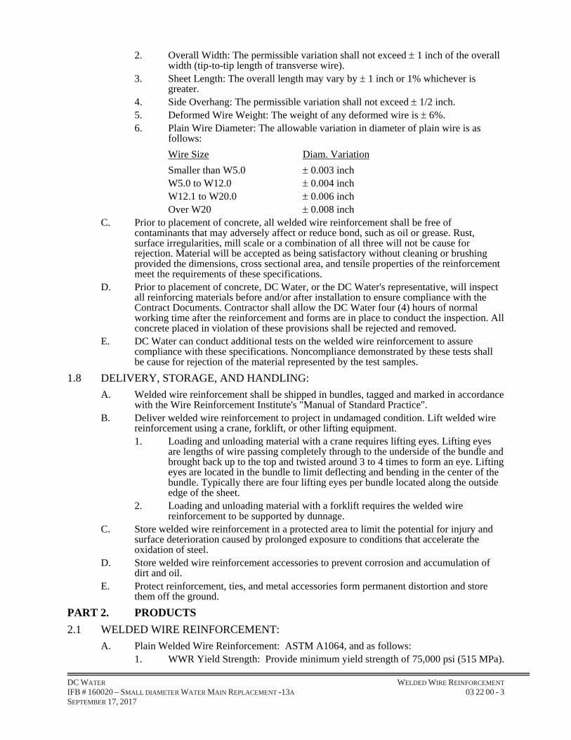
2. Overall Width: The permissible variation shall not exceed 1 inch of the overall width (tip-to-tip length of transverse wire).
3. Sheet Length: The overall length may vary by 1 inch or 1% whichever is greater.
4. Side Overhang: The permissible variation shall not exceed 1/2 inch. 5. Deformed Wire Weight: The weight of any deformed wire is 6%. 6. Plain Wire Diameter: The allowable variation in diameter of plain wire is as
follows:
Wire Size Diam. Variation
Smaller than W5.0 0.003 inch W5.0 to W12.0 0.004 inch W12.1 to W20.0 0.006 inch Over W20 0.008 inch
C. Prior to placement of concrete, all welded wire reinforcement shall be free of contaminants that may adversely affect or reduce bond, such as oil or grease. Rust, surface irregularities, mill scale or a combination of all three will not be cause for rejection. Material will be accepted as being satisfactory without cleaning or brushing provided the dimensions, cross sectional area, and tensile properties of the reinforcement meet the requirements of these specifications.
D. Prior to placement of concrete, DC Water, or the DC Water's representative, will inspect all reinforcing materials before and/or after installation to ensure compliance with the Contract Documents. Contractor shall allow the DC Water four (4) hours of normal working time after the reinforcement and forms are in place to conduct the inspection. All concrete placed in violation of these provisions shall be rejected and removed.
E. DC Water can conduct additional tests on the welded wire reinforcement to assure compliance with these specifications. Noncompliance demonstrated by these tests shall be cause for rejection of the material represented by the test samples.
1.8 DELIVERY, STORAGE, AND HANDLING:
A. Welded wire reinforcement shall be shipped in bundles, tagged and marked in accordance with the Wire Reinforcement Institute's "Manual of Standard Practice".
B. Deliver welded wire reinforcement to project in undamaged condition. Lift welded wire reinforcement using a crane, forklift, or other lifting equipment. 1. Loading and unloading material with a crane requires lifting eyes. Lifting eyes
are lengths of wire passing completely through to the underside of the bundle and brought back up to the top and twisted around 3 to 4 times to form an eye. Lifting eyes are located in the bundle to limit deflecting and bending in the center of the bundle. Typically there are four lifting eyes per bundle located along the outside edge of the sheet.
2. Loading and unloading material with a forklift requires the welded wire reinforcement to be supported by dunnage.
C. Store welded wire reinforcement in a protected area to limit the potential for injury and surface deterioration caused by prolonged exposure to conditions that accelerate the oxidation of steel.
D. Store welded wire reinforcement accessories to prevent corrosion and accumulation of dirt and oil.
E. Protect reinforcement, ties, and metal accessories form permanent distortion and store them off the ground.
PART 2. PRODUCTS
2.1 WELDED WIRE REINFORCEMENT:
A. Plain Welded Wire Reinforcement: ASTM A1064, and as follows: 1. WWR Yield Strength: Provide minimum yield strength of 75,000 psi (515 MPa).

DC WATER WELDED WIRE REINFORCEMENT IFB # 160020 – SMALL DIAMETER WATER MAIN REPLACEMENT -13A 03 22 00 - 4 SEPTEMBER 17, 2017
2. Welded wire reinforcement shall be manufactured from domestic steel. No foreign steel or foreign billets used in manufacturing process will be permitted. (This statement is typically used on Federal funded or DOT projects where domestic steel is required). Welded wire reinforcement shall be manufactured from foreign or domestic steel. (This statement is typically used on projects where domestic steel is not a requirement).
3. Wire Spacing and Size: Provide wire spacing and size, as calculated to maintain the specified area of steel as indicated on the contract drawings.
4. Wire used in the manufacturing of welded wire reinforcement shall conform to ASTM A1064.
5. Welded Wire Reinforcement shall be furnished in flat sheets or fabricated into bent sheets as indicated in the contract documents.
B. Deformed Welded Wire Reinforcement: ASTM A1064, and as follows: 1. WWR Yield Strength: Provide minimum yield strength of 80,000 psi (550 MPa). 2. Welded wire reinforcement shall be manufactured from domestic steel. No
foreign steel or foreign billets used in manufacturing process will be permitted. (This statement is typically used on Federal funded or DOT projects where domestic steel is required) Welded wire reinforcement shall be manufactured from foreign or domestic steel. (This statement is typically used on projects where domestic steel is not a requirement).
3. Wire Spacing and Size: Provide wire spacing and size, as calculated to maintain the specified area of steel as indicated on the Contract Drawings.
4. Wire used in the manufacturing of welded wire reinforcement shall conform to ASTM A1064.
5. Welded Wire Reinforcement shall be furnished in flat sheets or fabricated into bent sheets as indicated in the Contract Documents.
2.2 SUPPORTS:
A. Plastic or Wire Chairs, Bolsters, Bar Supports, Spacers: Sized and shaped for strength and support of reinforcement during concrete placement and construction loading conditions. Items shall conform to industry practice as described in the Wire Reinforcement Institute's, "Manual of Standard Practice" or "TF 702 – Supporting Welded Wire Reinforcement". 1. Metal bolsters or chairs which bear against the forms for exposed surfaces shall
be equipped with snug fitting, high density, polyethylene tips which provide 1/2" minimum clearance between the metal and any exposed surface.
2. For epoxy-coated reinforcement, all wire/ bar supports and bar clips shall be epoxy or plastic coated.
3. For galvanized reinforcing, chair and bar supports shall be hot-dipped galvanized, after fabrication, in accordance with ASTM A123.
4. Spacing of slab bolster rows and high chair rows for deck slabs shall be as noted in Wire Reinforcement Institute’s "Manual of Standard Practice" and "TF 702, Supporting Welded Wire Reinforcement" unless otherwise directed by the DC Water.
B. Concrete Blocks: Concrete blocks shall have a minimum bearing area of 2"X2" and equal in quality to the concrete specified. Concrete blocks can be used for supporting welded wire reinforcement in footings and slab-on-grades.
2.3 OTHER REINFORCEMENT:
A. Steel Reinforcing Bars: Reinforcing bars shall consist of deformed bars meeting the requirements of ASTM A615, Grade 60.
B. Dowel Bars: Dowel bars shall be round steel bars meeting the requirements of ASTM A36.
C. Tie Wire: Shall be 16-gauge, black soft-annealed wire conforming to ASTM A641.

DC WATER WELDED WIRE REINFORCEMENT IFB # 160020 – SMALL DIAMETER WATER MAIN REPLACEMENT -13A 03 22 00 - 5 SEPTEMBER 17, 2017
2.4 COATINGS:
A. Galvanizing for welded wire reinforcement shall be in accordance with ASTM A525. B. Epoxy Coatings for welded wire reinforcement shall be in accordance with ASTM A884.
Epoxy powders are electrostatically spray applied to a sandblasted near-white steel finish (fusion bonded epoxy resin). Ties, supports, and inserts used in conjunction with epoxy coated steel welded wire reinforcement shall be similarly coated.
PART 3. EXECUTION
3.1 EXAMINATION:
A. Examine conditions for compliance with requirements for installation tolerances and other specific conditions, and other conditions affecting performance of welded wire reinforcement.
B. Examine rough-in and built-in construction to verify actual locations of concrete penetrations prior to installation.
C. Do not proceed until unsatisfactory conditions have been corrected.
3.2 PREPARATION:
A. Clean all reinforcement by removing mud, oil, or other materials that will adversely affect or reduce bond at the time concrete is placed. Reinforcement with rust and/or mill scale will be accepted, provided the dimensions and weights, including heights or depth of deformations, are not less than required by the ASTM specification covering this reinforcement in this Specification.
B. Prior to placing welded wire reinforcement, remove laitance, loose materials, and anything that would prevent or hinder the installation of welded wire reinforcement.
3.3 INSTALLATION:
A. General: 1. Place supports to secure welded wire reinforcement against displacement caused
by construction loads or placing of concrete. Concrete blocks shall be used for supporting welded wire reinforcement in footings and slab-on-grades. For other concrete work, metal or plastic supports, hangers, or spacers maybe used. Layers of welded wire reinforcement shall be separated by chairs or bolsters. Stones, wood blocks, brick chips, etc., shall not be used to support reinforcement.
2. Place welded wire reinforcement to obtain at least minimum coverages for concrete protection.
3. Do not displace or damage vapor barrier. 4. Accommodate placement of formed openings. 5. Welded wire reinforcement sheets shall have side lap and end laps as called for
on the shop drawings. Laps shall be calculated in accordance with ACI 318 code. 6. Tie any added rebar with annealed iron wire of not less than 16 gauge or suitable
clips. Wire ties shall be cut back so that no metal is within 1" of the surface when the concrete is exposed to view.
3.4 CUT & REPAIR COATINGS:
A. Field Cutting: 1. Coated welded wire reinforcement shall not be field cut, unless permitted by DC
Water. 2. Field cutting of coated reinforcement should be performed using hydraulic-
powered or friction cutting tools to minimize coating damage and field touch-up. 3. Flame cutting of coated reinforcement will not be permitted. 4. Field cut coated reinforcement shall be repaired immediately with compatible
patching material and suitable for repairs in the field.

DC WATER WELDED WIRE REINFORCEMENT IFB # 160020 – SMALL DIAMETER WATER MAIN REPLACEMENT -13A 03 22 00 - 6 SEPTEMBER 17, 2017
B. Epoxy Coating Repair: 1. All visible damage (i.e., scratches, nicks, cracks) to the epoxy coating of the
welded wire reinforcement, caused during shipment, storage or placement shall be repaired by the Contractor at the job site with approved patching material.
2. Ends of reinforcement that have been sheared sawed, or cut by other means shall be coated with approved patching material.
3. Patching of damaged areas shall be performed in accordance with the patching material manufacturer’s recommendations.
4. Damaged surface area (prior to repair with approved patching material) shall not exceed 10% of the total sheet surface area, unless otherwise directed by the DC Water. Should this limit be exceeded the sheet shall be removed and replaced with an acceptable sheet.
5. Patching material shall be fully cured prior to placing concrete. The patching material shall be compatible with the epoxy coating, inert in concrete, and suitable for repairs in the field.
C. Galvanized Coating Repair: 1. All visible damage (i.e., scratches, nicks, cracks) to the galvanized coating of the
welded wire reinforcement, caused during shipment, storage or placement shall be repaired by the Contractor at the job site in accordance with appropriate ASTM specifications.
2. Ends of reinforcement that have been sheared, sawed, or cut by other means shall be coated.
3. Field coating of damaged areas shall be performed in accordance with the manufacturer’s recommendations.
4. Zinc coating shall conform to contract specifications and shall be applied to achieve a dry film equal to or exceeding that designated in the contract documents. All touchup shall be cured fully prior to placing concrete.
PART 4. MEASUREMENT AND PAYMENT
4.1 WELDED WIRE REINFORCEMENT:
A. Measurement: 1. Work for Welded Wire Reinforcement will not be measured separately for
payment. B. Payment:
1. No separate payment will be made for work under this Section. Payment for Welded Wire Reinforcement shall be considered incidental and included under the item of which it is a part of in the SOP’s, which price and payment shall include but not be limited to minor complications and/or delays, traffic maintenance and protection and all labor, materials, tools, fees and equipment necessary to complete the work as specified within this Contract.
~ END OF SECTION 03 22 00 ~
DC WATER CONCRETE ACCESSORIES IFB # 160020 – SMALL DIAMETER WATER MAIN REPLACEMENT -13A 03 25 00 - 1 SEPTEMBER 17, 2017
SECTION 03 25 00
CONCRETE ACCESSORIES
PART 1. GENERAL
1.1 SUMMARY:
A. Furnish all materials, labor, tools, equipment and incidentals required to make all joints tight in the concrete, as detailed on the Contract Drawings and as specified herein.
B. Requirements for providing concrete accessories shown and specified herein such as dovetail anchor slots, cast-in-place reglets, inserts, joint filler, and preformed joint sealant.
1.2 RELATED DOCUMENTS:
A. Drawings, Technical Specification Sections, General and Supplementary Conditions of the Contract and other Division 00 and Division 01 Specification Sections, apply to this Section.
B. Specifications throughout all Divisions of the Project Manual are directly pertinent to this Section, and this Section is directly pertinent to them.
1.3 RELATED SECTIONS: Specified elsewhere may include but are not limited to:
A. Section 01 33 00; Submittals
B. Section 03 10 00: Concrete Formwork
C. Section 03 15 16: Waterstops - Expanding
D. Section 03 20 00: Reinforcing Steel Rebars.
E. Section 03 30 00: Cast-In-Place Concrete.
1.4 QUALITY ASSURANCE:
A. American Association of State Highway and Transportation Officials (AASHTO):
1. AASHTO M282: "Joint Sealants, Hot-Poured, Elastomeric-Type, For Portland Cement Concrete Pavements".
B. American Society of Testing and Materials (ASTM):
1. ASTM C881: “Standard Specification for Epoxy-Resin-Base Bonding Systems for Concrete”.
2. ASTM Dl752: "Specification for Preformed Sponge Rubber and Cork Expansion Joint Fillers for Concrete Paving and Structural Construction".
3. ASTM D7234: “Standard Test Method for Pull-Off Adhesion Strength of Coatings on Concrete Using Portable Pull-Off Adhesion Testers”.
1.5 SUBMITTALS:
A. Requirements for “Submittals” shall be in accordance to Section 01 33 00.
B. Submit Certifications for each of the materials specified herein, which will be used on the project, with the manufacturer’s Certificate of Compliance stating “Concrete Accessories” materials meet or exceed the specified requirements.
C. Submit a proposed list of sources of all material. Sources shall be approved by the jurisdiction DOT where the project is being performed and shall include a copy of their certification of each source.

DC WATER CONCRETE ACCESSORIES IFB # 160020 – SMALL DIAMETER WATER MAIN REPLACEMENT -13A 03 25 00 - 2 SEPTEMBER 17, 2017
D. Submit the “Installation Instructions and Details” describing and showing how the Concrete Accessories will be installed.
E. Submit the “Product Data Sheets” of each product used.
F. Submit the “Samples” of each product used.
PART 2. PRODUCT
2.1 MATERIALS:
A. Requirements for “Waterstops” shall be in accordance to Section 03 15 16.
B. Water stops shall be of the highest-grade polyvinyl chloride per Corps of Engineers Specification CRD C572. Water stops shall be 9-inch dumbbell type for construction joints and dumbbell type with center bulb for expansion joints. Use of reclaimed PVC is prohibited
C. Water stops shall be flat ribbed type for construction joints and for dumbbell type for expansion joints. Both construction and expansion joint waterstops shall have a minimum thickness at any point of 3/8-inch, unless shown or specified otherwise. The bulbs shall have a minimum outside diameter of 1-inch and a minimum inside diameter of ½-inch unless shown or specified otherwise.
D. Expanding rubber waterstop shall be a chemically modified natural rubber product designed to expand under hydrostatic conditions with a hydrophilic agent and a stainless steel mesh or co-extrusion of non-hydrophilic rubber to direct expansion in the thickness direction and restrict the expansion in the longitudinal direction.
E. Preformed expansion joint filler shall be per ASTM D1752, Type II or III. Premolded joint filler shall be of suitable length to minimize splices and of proper width to eliminate field cutting longitudinally.
F. Joint sealant for joints in slabs and walls shall be per AASHTO M282. Bond breaker shall be a suitable polyethylene tape of correct width to suit joint conditions. The sealant manufacturer shall submit written certification that the sealant is resistant to acid (down to a pH of 3.5) and alkali (up to a pH of 8.5).
G. Flashing Reglets: Provide flashing reglets of 24 gauge galvanized steel foam filled reglets.
H. Dovetail Anchors: Provide dovetail anchors having a 3/16-inch by 1-inch by ½-inch stainless steel dovetail section with 3/16-inch diameter stainless steel wire.
I. Epoxy Bonding Agents: Provide epoxy bonding agent conforming to ASTM C881
PART 3. EXCECUTION
3.1 CONSTRUCTION REQUIREMENTS:
A. Footings, beams and slabs shall have no horizontal joints.
B. Construction joints shall be placed and secured perpendicular to the face of the concrete section.
C. Defective joints and defective and improperly placed sealers and sealants shall be removed and reconstructed at Contractor expense.
D. Water Stops:
1. Water stops for all joints, as indicated on the Contract Drawings, shall be placed without bends but shall be continuous around all corners and intersections.
DC WATER CONCRETE ACCESSORIES IFB # 160020 – SMALL DIAMETER WATER MAIN REPLACEMENT -13A 03 25 00 - 3 SEPTEMBER 17, 2017
Splices shall be made by welding per manufacturer's recommendations, subject to DC Water’s approval.
2. Make provisions to support and protect water-stops during the progress of the work. Fabricate field joints in waterstops per manufacturer's printed instructions. Protect waterstop material from damage where it protrudes from any joints.
3. A sufficient number of ties shall be placed, as directed, to insure that waterstops will remain in the required position during concrete placement.
E. Preformed Expansion Joint Filler:
1. Expansion joint filler shall be furnished in the longest practicable lengths, but shall not be furnished or stored in rolls. Laitance shall be removed and joint faces acceptably cleaned before placing preformed joint material.
2. Joint filler shall be fastened to the inside of the bulkhead form with non-corrodible fasteners to secure a mechanical bond with concrete placed on both sides of the filler. Material shall be so placed that exposed edge is within 1/8 inch for a 1/4 inch joint, in order that filler material edge can be lightly ground to provide uniform sealant depth.
3. Care shall be taken at all times to prevent any disturbance of or damage to the joint filler.
4. Field splices shall be made per manufacturer's recommendations for total contact fit.
F. Joint Sealant:
1. Before sealing joint edges with sealants, all mortar, surface coatings, form coating, moisture, spalls, protrusions, dust, oil, grease, and frost shall be removed as approved by the DC Water by use of grinding, sandblasting, mechanical abrading, acid washing, or a combination of these methods to provide a clean, sound base for sealant adhesion. Heat shall be applied to dry out joints where required. Loose particles present or resulting from grinding, abrading or blast cleaning shall be removed by blowing out joints with oil-free compressed air prior to application of primer or sealant. Where concrete has spalled or broken, an epoxy grout shall be used to repair the concrete to give a uniform width of joint. The epoxy shall be DC Water approved and shall be applied as directed by the manufacturer.
2. No sealant shall be placed until at least 28 days after the concrete is placed. Polyethylene bond breaker tape of correct width and length shall be placed over the joint edge.
3. Sealant shall be applied by experienced applicators in strict accordance with manufacturer's recommendations. Joint sealer shall be applied when the ambient temperature is between 60 degrees and 80 degrees F.
4. All concrete joint faces to be sealed shall be primed with a primer recommended by the sealant manufacturer. The primer shall dry for the length of time recommended by the sealant manufacturer before applying the sealant. The sealant shall be placed before the primer has dried out, so that it will provide the proper bond. If the primer dries out, another prime coat shall be applied before placing the sealant.
5. Sealant shall be installed within the time limit specified. All material not used after this time shall be discarded.
6. The application, tooling and finishing of the sealant shall be as recommended by the manufacturer. Sealant surfaces shall be smooth and even.

DC WATER CONCRETE ACCESSORIES IFB # 160020 – SMALL DIAMETER WATER MAIN REPLACEMENT -13A 03 25 00 - 4 SEPTEMBER 17, 2017
7. Adjacent surfaces shall be cleaned free of sealant or soiling as the work progresses. Use solvent or cleaning agent as recommended by the sealant manufacturer. All finish work shall be left in neat, clean condition.
8. Pull-Off Adhesion Test shall be in accordance with ASTM D7234.
G. Epoxy Bonding Agent:
1. Contractor shall use an epoxy bonding agent for bonding fresh concrete to existing concrete.
PART 4. MEASUREMENT AND PAYMENT
4.1 CONCRETE ACCESSORIES:
A. Measurement:
1. Work for Concrete Accessories will not be measured separately for payment.
B. Payment:
1. No separate payment will be made for work under this Section. Payment for Concrete Accessories shall be considered incidental and included in the payment for the item of which it is a part of in the SOP’s, which price and payment shall include but not be limited to minor complications and/or delays, traffic maintenance and protection and all labor, materials, tools, fees and equipment necessary to complete the work as specified within this Contract.
~ END OF SECTION 03 25 00 ~
DC WATER JOINTS IN CONCRETE IFB # 160020 – SMALL DIAMETER WATER MAIN REPLACEMENT -13A 03 29 00 - 1 SEPTEMBER 17, 2017
SECTION 03 29 00
JOINTS IN CONCRETE
PART 1 GENERAL
1.1 SUMMARY:
A. The Contractor shall construct all joints and bearing pads in concrete at the locations shown. Joints required in concrete structures are of various types and will be permitted only where shown, unless specifically accepted by DC Water.
1.2 RELATED DOCUMENTS:
A. Drawings, Technical Specification Sections, General and Supplementary Conditions of the Contract and other Division 00 and Division 01 Specification Sections, apply to this Section.
B. Specifications throughout all Divisions of the Project Manual are directly pertinent to this Section, and this Section is directly pertinent to them.
1.3 RELATED SECTIONS: Specified elsewhere may include but are not limited to:
A. Section 01 33 00: Submittals B. Section 03 15 13: Waterstops Non-Expanding C. Section 03 15 16: Waterstops - Expanding D. Section 03 30 00: Cast-in-Place Concrete
1.4 REFERENCE CODES:
A. Comply with the current provisions of the following Codes and Standards, as pertinent: 1. U.S. Army Corps of Engineers Specifications: CRD-C572 Pollyinylchlorid3e
Waterstop. 2. District of Columbia Department of Transportation:
a. Standard Specification for Highway and Structures. b. Standard Engineering Drawings for Highway and Structures.
3. American Society for Testing and Materials: a. ASTM C920: “Elastomeric Joint Sealants”. b. ASTM D570: “Standard Test Method for Water Absorption of Plastics”. c. ASTM D624: “Standard Test Method for Rubber Property - Tear
Resistance”. d. ASTM D638: “Standard Test Method for Tensile Properties of Plastics”. e. ASTM D746: “Standard Test Method for Brittleness Temperature of
Plastics and Elastomers by Impact”. f. ASTM D747: “Standard Test Method for Apparent Bending Modulus of
Plastics by Means of a Cantilever Beam”. g. ASTM D 994: “Standard Specification for Preformed Expansion Joint
Filler for Concrete (Bituminous Type)”. h. ASTM D1149: “Standard Test Methods for Rubber Deterioration—
Cracking in an Ozone Controlled Environment”. i. ASTM D1203: “Standard Test Methods for Volatile Loss From Plastics
Using Activated Carbon Methods”. j. ASTM D1752: “Standard Specification for Preformed Sponge Rubber
and Cork Expansion Joint Fillers for Concrete Paving and Structural Construction”.
k. ASTM D2240: “Standard Test Method for Rubber Property - Durometer Hardness”.
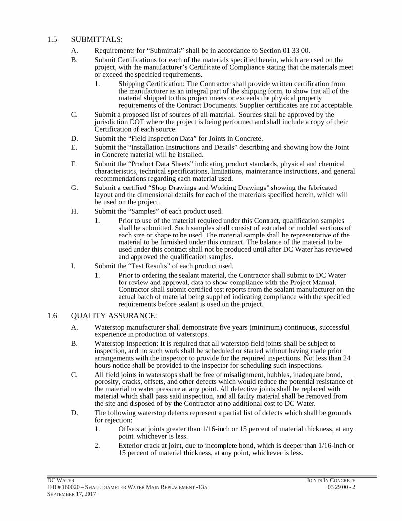
DC WATER JOINTS IN CONCRETE IFB # 160020 – SMALL DIAMETER WATER MAIN REPLACEMENT -13A 03 29 00 - 2 SEPTEMBER 17, 2017
1.5 SUBMITTALS:
A. Requirements for “Submittals” shall be in accordance to Section 01 33 00. B. Submit Certifications for each of the materials specified herein, which are used on the
project, with the manufacturer’s Certificate of Compliance stating that the materials meet or exceed the specified requirements. 1. Shipping Certification: The Contractor shall provide written certification from
the manufacturer as an integral part of the shipping form, to show that all of the material shipped to this project meets or exceeds the physical property requirements of the Contract Documents. Supplier certificates are not acceptable.
C. Submit a proposed list of sources of all material. Sources shall be approved by the jurisdiction DOT where the project is being performed and shall include a copy of their Certification of each source.
D. Submit the “Field Inspection Data” for Joints in Concrete. E. Submit the “Installation Instructions and Details” describing and showing how the Joint
in Concrete material will be installed. F. Submit the “Product Data Sheets” indicating product standards, physical and chemical
characteristics, technical specifications, limitations, maintenance instructions, and general recommendations regarding each material used.
G. Submit a certified “Shop Drawings and Working Drawings” showing the fabricated layout and the dimensional details for each of the materials specified herein, which will be used on the project.
H. Submit the “Samples” of each product used. 1. Prior to use of the material required under this Contract, qualification samples
shall be submitted. Such samples shall consist of extruded or molded sections of each size or shape to be used. The material sample shall be representative of the material to be furnished under this contract. The balance of the material to be used under this contract shall not be produced until after DC Water has reviewed and approved the qualification samples.
I. Submit the “Test Results” of each product used. 1. Prior to ordering the sealant material, the Contractor shall submit to DC Water
for review and approval, data to show compliance with the Project Manual. Contractor shall submit certified test reports from the sealant manufacturer on the actual batch of material being supplied indicating compliance with the specified requirements before sealant is used on the project.
1.6 QUALITY ASSURANCE:
A. Waterstop manufacturer shall demonstrate five years (minimum) continuous, successful experience in production of waterstops.
B. Waterstop Inspection: It is required that all waterstop field joints shall be subject to inspection, and no such work shall be scheduled or started without having made prior arrangements with the inspector to provide for the required inspections. Not less than 24 hours notice shall be provided to the inspector for scheduling such inspections.
C. All field joints in waterstops shall be free of misalignment, bubbles, inadequate bond, porosity, cracks, offsets, and other defects which would reduce the potential resistance of the material to water pressure at any point. All defective joints shall be replaced with material which shall pass said inspection, and all faulty material shall be removed from the site and disposed of by the Contractor at no additional cost to DC Water.
D. The following waterstop defects represent a partial list of defects which shall be grounds for rejection: 1. Offsets at joints greater than 1/16-inch or 15 percent of material thickness, at any
point, whichever is less. 2. Exterior crack at joint, due to incomplete bond, which is deeper than 1/16-inch or
15 percent of material thickness, at any point, whichever is less.

DC WATER JOINTS IN CONCRETE IFB # 160020 – SMALL DIAMETER WATER MAIN REPLACEMENT -13A 03 29 00 - 3 SEPTEMBER 17, 2017
3. Any combination of offset or exterior crack which will result in a net reduction in the cross section of the waterstop in excess of 1/16-inch or 15 percent of material thickness at any point, whichever is less.
4. Misalignment of joint which result in misalignment of the waterstop in excess of 1/2-inch in 10 feet.
5. Porosity in the welded joint as evidenced by visual inspection. 6. Bubbles or inadequate bonding.
E. Waterstop Samples: Prior to use of the waterstop material in the field, Contractor shall submit a sample of a fabricated metered cross and a tee constructed of each size or shape of material to be used shall be submitted to DC Water for approval. These samples shall be fabricated so that the material and workmanship represent in all respects the fittings to be furnished under this contract. Field samples of fabricated fittings (crosses, tees, etc.) will be selected at random by the inspector for testing. When tested, they shall have a tensile strength across the joints equal to at least 600 psi.
F. Construction Joint Sealant: The Contractor shall prepare adhesion and cohesion test specimens as specified herein, at intervals of 5 working days while sealants are being installed.
G. The sealant material shall show no signs of adhesive or cohesive failure when tested in accordance with the following procedure in laboratory and field tests: 1. Sealant specimen shall be prepared between 2 concrete blocks (1-inch by 2-inch
by 3-inch). Spacing between the blocks shall be 1/2-inch. Coated spacers (2-inch by 1-1/2-inch by 1/2-inch) shall be used to insure sealant cross-sections of 1/2-inch by 2 inches with a width of 1/2-inch.
2. Sealant shall be cast and cured accordance to the manufacturer's recommendations except that curing period shall not exceed 24 hours.
3. Following curing period, the gap between blocks shall be widened to one inch. Spacers shall be used to maintain this gap for 24 hours prior to inspection for failure.
H. Store waterstops under tarps to protect from oil, dirt, and sunlight.
1.7 TYPES OF JOINTS:
A. Construction Joints: When fresh concrete is placed against a hardened concrete surface, the joint between the two pours is called a construction joint. Unless otherwise specified, all joints in water bearing members shall be provided with a waterstop and sealant groove of the shape specified and as shown on the Contract Drawings.
B. Contraction Joints: Contraction joints are similar too construction joints except that the fresh concrete shall not bond to the hardened surface of the first pour, which shall be coated with a bond breaker. The slab reinforcement shall be stopped 4-1/2 inches from the joint, unless noted otherwise; which is provided with a sleeve-type dowel, to allow shrinkage of the concrete of the second pour. Waterstop and sealant groove shall also be provided.
C. Expansion Joints: To allow the concrete to expand freely, a space is provided between the two pours, the joint shall be formed as shown or stated on the plans. This space is obtained by placing a filler joint material against the first pour, which acts as a form for the second pour. Unless otherwise specified, all expansion joints in water bearing members shall be provided with an approved type waterstop. Preformed expansion joint material shall be installed with the edge at the indicated distance below or back from finished concrete surface, and shall have a slightly tapered, dressed, and oiled wood strip secured to or placed at the edge thereof during concrete placement, which shall later be removed to form space for sealing material. The space so formed shall be filled with a joint sealant material as specified herein entitled "Joint Sealant." In order to keep the two elements in line the joint shall be provided with a sleeve-type dowel as shown.
D. Control Joints (Weakened Plane): The function of the control joint is to provide a weaker plane in the concrete, where shrinkage cracks will probably occur. A groove, of the shape and dimensions as shown on the plans, is formed or saw-cut in the concrete and shall be filled with a joint sealant material as specified herein entitled "Joint Sealant."

DC WATER JOINTS IN CONCRETE IFB # 160020 – SMALL DIAMETER WATER MAIN REPLACEMENT -13A 03 29 00 - 4 SEPTEMBER 17, 2017
1.8 GUARANTEE:
A. The Contractor shall provide a 5-year written guarantee of the entire sealant installation against faulty and/or incompatible materials and workmanship, together with a statement that it agrees to repair or replace, to the satisfaction of DC Water, at no additional cost to DC Water, any such defective areas which become evident within said 5-year guarantee period.
PART 2 PRODUCTS
2.1 WATERSTOPS:
A. Requirements for “Waterstops Non-Expanding shall be in accordance to Section 03 15 13.
B. Requirements for “Waterstops - Expanding shall be in accordance to Section 03 15 16.
2.2 PVC WATERSTOPS:
A. General: Waterstops shall be extruded from an elastomeric polyvinyl chloride compound containing the plasticizers, resins, stabilizers, and other materials necessary to meet the requirements of these Specifications; No reclaimed or scrap material shall be used. The Contractor shall obtain from the waterstop manufacturer and shall furnish to the DC Water for review, current test reports and a written certification of the manufacturer that the material to be shipped to the job meets the physical requirements as outlined in the U.S. Army Corps of Engineers Specification CRD-C572 and those listed herein.
B. Flatstrip and Center-Bulb Waterstops: Flatstrip and center-bulb waterstops shall be as detailed and as manufactured by: [BoMetals, Inc., Carrollton, Ga.; Kirkhill Rubber Co., Brea, California; Greenstreak, St. Louis, MO, Water Seals, Inc., Chicago, Illinois; Progress Unlimited, Inc., New York, New York]; or an approved equal; provided, that at no place shall the thickness of flat strip waterstops, including the center bulb type, be less than 3/8-inch.
C. Multi-Rib Waterstops: Multi-rib waterstops, where required, shall be as detailed and as manufactured by [BoMetals, Inc. Carrrollton, Ga.; Vinylex, St. Louis, Mo.; Water Seals, Inc., Chicago, Illinois; Progress Unlimited, Inc., New York, New York; Greenstreak, St. Louis, MO], or an approved equal. Prefabricated joint fittings shall be used at all intersections of the ribbed-type waterstops.
D. Other Types of Waterstops: When other types of waterstops, not listed above are required and shown, they shall be subjected to the same requirements as those listed herein.
E. Waterstop Testing Requirements: When tested in accordance with the specified test standards, the waterstop material shall meet or exceed the following requirements: 1. Tensile Strength 1750 psi (min), (ASTM D638, Type IV) 2. Ultimate Elongation 300% min. (ASTM D638, Type IV) 3. Low Temp Brittleness No Failure at -35oF, (ASTMD746) 4. Stiffness in Flexure 600 psi (ASTM D747) 5. Tensile Strength After Accelerated Extraction:1500 psi (CRD-C572) 6. Elongation After Accelerated Extraction:280% min (CRD-C572) 7. Effect of Alkalis After 7 days, Change in weight 0.25% to -0.10% (CRD-
C572) 8. Effect of Alkalis After 7 days, Change in Hardness, Shore A 5 Max
(CRD-C 572) 9. Water Absorption 5% max. (ASTM D570) 10. Tear Resistance 250 lb/in min. (ASTM D624) 11. Hardness Shore A 65 to 80 (ASTM D624) 12. Ozone Resistance No Failure (ASTM D1149) 13. Volatile Loss 0.50% max. (ASTM D1203)
F. Accessories:

DC WATER JOINTS IN CONCRETE IFB # 160020 – SMALL DIAMETER WATER MAIN REPLACEMENT -13A 03 29 00 - 5 SEPTEMBER 17, 2017
1. Provide factory made waterstop fabrications for all changes of direction, intersections, and transitions leaving only straight butt joint splices for the field.
2. Provide hog rings or grommets spaced at 12 inches on center along length of waterstop.
3. Provide Teflon coated thermostatically controlled waterstop splicing irons for field butt splices.
2.3 JOINT SEALANT:
A. Joint sealant material shall be elastomeric conforming to ASTM C920 Type M (multi-component) and designated for Use I (immersed), Use T (traffic) or NT (non-traffic) as appropriate. Primer materials shall conform to the printed recommendations of the sealant manufacturer. Sealants shall meet the following minimum requirements, plus the characteristics specified herein based on various application conditions: 1. Ultimate Hardness 20 Shore "A" minimum. 2. Tensile Strength 95 psi, minimum. 3. Percent Elongation 240 percent, minimum. 4. Color Light Gray
B. Sealants for joints in potable retaining structures shall be polyswulfide-based non-sag and conform to ASTM C920, type M, Grade NS, Class 25. Acceptable Products: 1. Pecora Corporation Synthacalk GC2+ 2. The Euclid Chemical Co. Tammsflex NS 3. PolySpec Thiokol 2235M 4. Or Approved Equal
C. Sealants for joints in water retaining structures containing non-potable water shall be polyurethane-based, non-sag, and conform to ASTM C920, Type M, Grade NS, Class 25. Acceptable Products: 1. Sika Corporation Sikaflex-2c NS 2. BASF Corporation MasterSeal NP2 3. Tremco Commercial Sealants & Waterproofing Dymeric 240 4. Or Approved Equal
D. Sealants for joints in non-water retaining structures not requiring chemical resistant properties and installed in a horizontal application shall be polyurethane-based, self- leveling, and conform to ASTM C920, Type M, Grade P, Class 25. Acceptable Products: 1. Sika Corporation Sikaflex-2c SL 2. BASF Corporation MasterSeal SL2 3. Tremco Commercial Sealants & Waterproofing Vulkem 445SSL 4. Or Approved Equal
E. Sealants for joints in non-water retaining structures not requiring chemical resistant properties and installed in a vertical or overhead application shall be polyurethane-based, non-sag, and shall conform to ASTM C920, Type M, Grade NS, Class 25. Acceptable Products: 1. Sika Corporation Sikaflex-2c NS 2. BASF Corporation MasterSeal NP2 3. Tremco Commercial Sealants & Waterproofing Dymeric 240 4. Or Approved Equal
F. Sealants for joints in non-water retaining structures requiring chemical resistant properties and installed in a horizontal application shall be polysulfide-based, non-sag, self-leveling and shall conform to ASTM C920, Type M, Grade P, Class 25. Acceptable Products: 1. Sika Corporation Duoflex-SL 2. The Euclid Chemical Co Tammsflex SL

DC WATER JOINTS IN CONCRETE IFB # 160020 – SMALL DIAMETER WATER MAIN REPLACEMENT -13A 03 29 00 - 6 SEPTEMBER 17, 2017
3. PolySpec Thiokol 2235SL 4. Or Approved Equal
G. Sealants for joints in non-water retaining structures requiring chemical resistant properties and installed in a vertical or overhead application shall be polysulfide-based, non-sag, and shall conform to ASTM C920, Type M, Grade NS, Class 25. Acceptable Products: 1. Sika Corporation Duoflex-NS 2. The Euclid Chemical Co Tammsflex NS 3. PolySpec Thiokol 2235M 4. Or Approved Equal
2.4 PREFORMED JOINT FILLER:
A. Preformed joint filler material shall be of the preformed non-extruding type joint filler constructed of cellular neoprene sponge rubber or polyurethane of firm texture. Bituminous fiber type will not be permitted. All non-extruding and resilient-type preformed expansion joint fillers shall conform to the requirements and tests set forth in ASTM D 1752 for Type I (Sponge Rubber), except as otherwise specified herein.
B. Unless otherwise noted, preformed joint filler shall be a non-extruding, resilient, bituminous type conforming to the requirements of ASTM D 994.
2.5 BACKING ROD:
A. Backing rod shall be an extruded closed-cell, polyethylene foam rod. The material shall be compatible with the joint sealant material used and shall have a tensile strength of not less than 40 psi and a compression deflection of approximately 25 percent at 8 psi. The rod shall be 1/8-inch larger in diameter than the joint width except that a one-inch diameter rod shall be used for a 3/4-inch wide joint.
2.6 BOND BREAKER:
A. Bond breaker shall be an adhesive backed glazed butyl or polyethylene tape that will adhere to the preformed joint material or concrete surface. The tape shall be the same width as the joint. The tape shall be compatible with the sealant.
PART 3 EXECUTION
3.1 GENERAL:
A. Unless otherwise shown, waterstops of the type specified herein shall be embedded in the concrete across joints as shown. All waterstops shall be fully continuous for the extent of the joint. Splices necessary to provide such continuity shall be accomplished in conformance to printed instructions of manufacturer of the waterstops. The Contractor shall take suitable precautions and means to support and protect the waterstops during the progress of the work and shall repair or replace at its own expense any waterstops damaged during the progress of the work. All waterstops shall be stored to permit free circulation of air around the waterstop material.
B. When any waterstop is installed in the concrete on one side of a joint, while the other half or portion of the waterstop remains exposed to the atmosphere for more than 2 days, suitable precautions shall be taken to shade and protect the exposed waterstop from direct rays of the sun during the entire exposure and until the exposed portion of the waterstop is embedded in concrete.
3.2 SPLICES IN WATERSTOPS:
A. Splices in waterstops shall be performed by heat sealing the adjacent waterstop sections in accordance with the manufacturer's printed recommendations and the following requirements: 1. The material not be damaged by heat sealing. 2. The splices have a tensile strength of not less than 60 percent of the un-spliced
materials tensile strength.
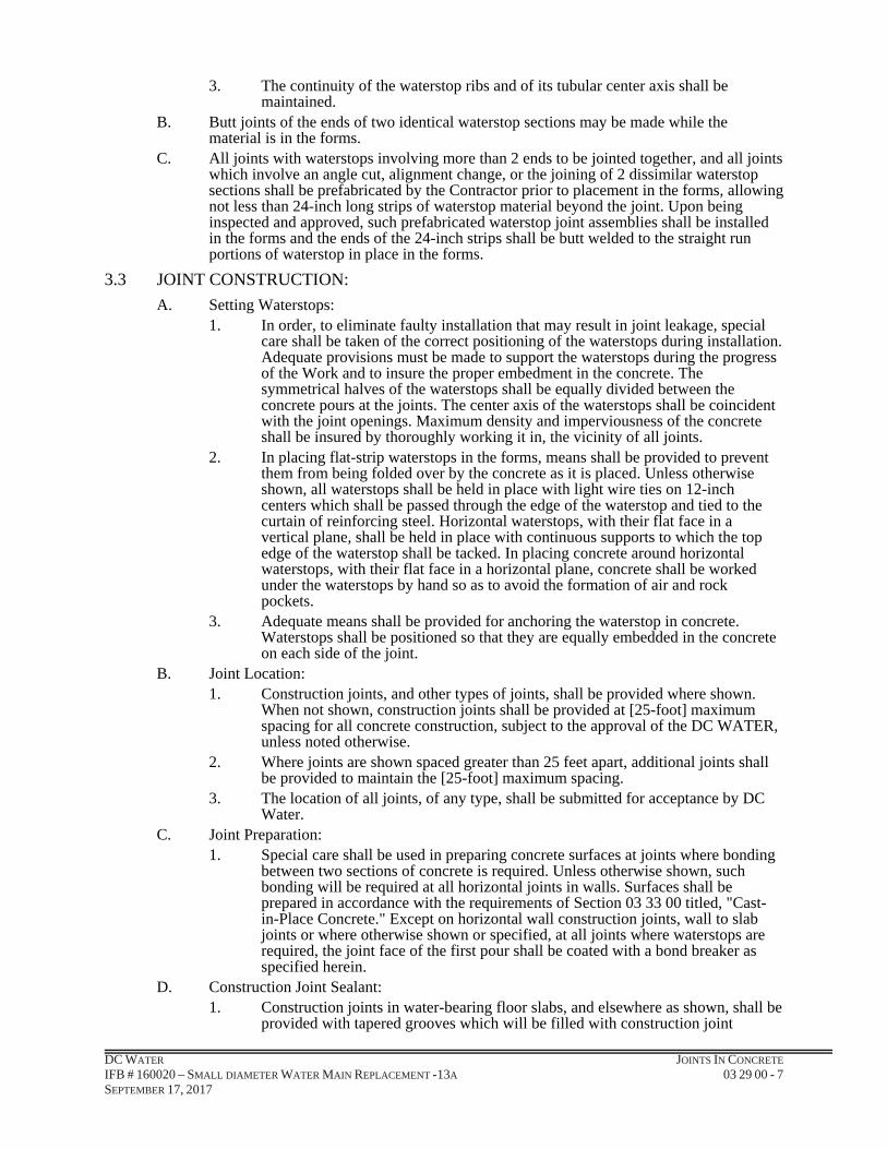
DC WATER JOINTS IN CONCRETE IFB # 160020 – SMALL DIAMETER WATER MAIN REPLACEMENT -13A 03 29 00 - 7 SEPTEMBER 17, 2017
3. The continuity of the waterstop ribs and of its tubular center axis shall be maintained.
B. Butt joints of the ends of two identical waterstop sections may be made while the material is in the forms.
C. All joints with waterstops involving more than 2 ends to be jointed together, and all joints which involve an angle cut, alignment change, or the joining of 2 dissimilar waterstop sections shall be prefabricated by the Contractor prior to placement in the forms, allowing not less than 24-inch long strips of waterstop material beyond the joint. Upon being inspected and approved, such prefabricated waterstop joint assemblies shall be installed in the forms and the ends of the 24-inch strips shall be butt welded to the straight run portions of waterstop in place in the forms.
3.3 JOINT CONSTRUCTION:
A. Setting Waterstops: 1. In order, to eliminate faulty installation that may result in joint leakage, special
care shall be taken of the correct positioning of the waterstops during installation. Adequate provisions must be made to support the waterstops during the progress of the Work and to insure the proper embedment in the concrete. The symmetrical halves of the waterstops shall be equally divided between the concrete pours at the joints. The center axis of the waterstops shall be coincident with the joint openings. Maximum density and imperviousness of the concrete shall be insured by thoroughly working it in, the vicinity of all joints.
2. In placing flat-strip waterstops in the forms, means shall be provided to prevent them from being folded over by the concrete as it is placed. Unless otherwise shown, all waterstops shall be held in place with light wire ties on 12-inch centers which shall be passed through the edge of the waterstop and tied to the curtain of reinforcing steel. Horizontal waterstops, with their flat face in a vertical plane, shall be held in place with continuous supports to which the top edge of the waterstop shall be tacked. In placing concrete around horizontal waterstops, with their flat face in a horizontal plane, concrete shall be worked under the waterstops by hand so as to avoid the formation of air and rock pockets.
3. Adequate means shall be provided for anchoring the waterstop in concrete. Waterstops shall be positioned so that they are equally embedded in the concrete on each side of the joint.
B. Joint Location: 1. Construction joints, and other types of joints, shall be provided where shown.
When not shown, construction joints shall be provided at [25-foot] maximum spacing for all concrete construction, subject to the approval of the DC WATER, unless noted otherwise.
2. Where joints are shown spaced greater than 25 feet apart, additional joints shall be provided to maintain the [25-foot] maximum spacing.
3. The location of all joints, of any type, shall be submitted for acceptance by DC Water.
C. Joint Preparation: 1. Special care shall be used in preparing concrete surfaces at joints where bonding
between two sections of concrete is required. Unless otherwise shown, such bonding will be required at all horizontal joints in walls. Surfaces shall be prepared in accordance with the requirements of Section 03 33 00 titled, "Cast-in-Place Concrete." Except on horizontal wall construction joints, wall to slab joints or where otherwise shown or specified, at all joints where waterstops are required, the joint face of the first pour shall be coated with a bond breaker as specified herein.
D. Construction Joint Sealant: 1. Construction joints in water-bearing floor slabs, and elsewhere as shown, shall be
provided with tapered grooves which will be filled with construction joint

DC WATER JOINTS IN CONCRETE IFB # 160020 – SMALL DIAMETER WATER MAIN REPLACEMENT -13A 03 29 00 - 8 SEPTEMBER 17, 2017
sealant. The material used for forming the tapered grooves shall be left in the grooves until just before the grooves are cleaned and filled with joint sealant. After removing the forms from the grooves, all laitance and fins shall be removed, and the grooves shall be sand-blasted. The grooves shall be allowed to become thoroughly dry, after which they shall be blown out; immediately thereafter, they shall be primed and filled with the construction joint sealant. The primer used shall be supplied by the same manufacturer supplying the sealant. No sealant will be permitted to be used without a primer. Care shall be used to completely fill the sealant grooves. Areas designated to receive a sealant filler shall be thoroughly cleaned, as outlined for the tapered grooves, prior to application of the sealant.
2. Sealant application shall be in accordance with the manufacturer's printed instructions. The surfaces of the groove for the sealant shall not be coated. Concrete next to waterstops shall be placed in accordance with the requirements of Section 03 33 00 titled, “Cast-in-Place Concrete”.
3. The primer and sealant shall be placed strictly in accordance with the printed recommendations of the manufacturer, taking special care to properly mix the sealant prior to application. All sealant shall cure at least 7 days before the structure is filled with water.
4. All sealant shall be installed by a competent waterproofing specialty contractor who has a successful record of performance in similar installations. Before work is commenced, the crew doing the Work shall be instructed as to the proper method of application by a representative of the sealant manufacturer.
5. Thorough, uniform mixing of 2-part, catalyst-cured materials is essential; special care shall be taken to properly mix the sealer before its application. Before any sealer is placed, the Contractor shall arrange to have the crew doing the Work carefully instructed as to the proper method of mixing and application by a representative of the sealant manufacturer.
6. Any joint sealant which after the manufacturer's recommended curing time for the job conditions of the Work hereunder, fails to fully and properly cure shall be completely removed; the groove shall be thoroughly sandblasted to remove all traces of the uncured or partially cured sealant and primer, and shall be re-sealed with the specified joint sealant. All costs of such removal, joint treatment, re-sealing, and appurtenant work shall be at the expense of the Contractor.
PART 4 MEASUREMENT AND PAYMENT
4.1 JOINTS IN CONCRETE:
A. Measurement: 1. Work for Concrete Joints will not be measured separately for payment.
B. Payment: 1. No separate payment will be made for work under this Section. Payment for
Concrete Joints shall be considered incidental and included under the item of which it is a part of in the SOP’s, which price and payment shall include but not be limited to minor complications and/or delays, traffic maintenance and protection and all labor, materials, tools, fees and equipment necessary to complete the work as specified within this Contract.
~ END OF SECTION 03 29 00 ~
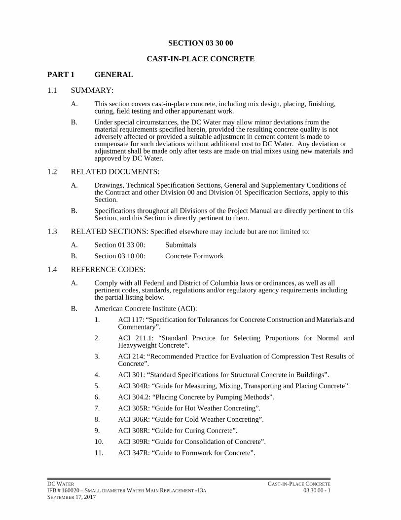
DC WATER CAST-IN-PLACE CONCRETE IFB # 160020 – SMALL DIAMETER WATER MAIN REPLACEMENT -13A 03 30 00 - 1 SEPTEMBER 17, 2017
SECTION 03 30 00
CAST-IN-PLACE CONCRETE
PART 1 GENERAL
1.1 SUMMARY:
A. This section covers cast-in-place concrete, including mix design, placing, finishing, curing, field testing and other appurtenant work.
B. Under special circumstances, the DC Water may allow minor deviations from the material requirements specified herein, provided the resulting concrete quality is not adversely affected or provided a suitable adjustment in cement content is made to compensate for such deviations without additional cost to DC Water. Any deviation or adjustment shall be made only after tests are made on trial mixes using new materials and approved by DC Water.
1.2 RELATED DOCUMENTS:
A. Drawings, Technical Specification Sections, General and Supplementary Conditions of the Contract and other Division 00 and Division 01 Specification Sections, apply to this Section.
B. Specifications throughout all Divisions of the Project Manual are directly pertinent to this Section, and this Section is directly pertinent to them.
1.3 RELATED SECTIONS: Specified elsewhere may include but are not limited to:
A. Section 01 33 00: Submittals
B. Section 03 10 00: Concrete Formwork
1.4 REFERENCE CODES:
A. Comply with all Federal and District of Columbia laws or ordinances, as well as all pertinent codes, standards, regulations and/or regulatory agency requirements including the partial listing below.
B. American Concrete Institute (ACI):
1. ACI 117: “Specification for Tolerances for Concrete Construction and Materials and Commentary”.
2. ACI 211.1: “Standard Practice for Selecting Proportions for Normal and Heavyweight Concrete”.
3. ACI 214: “Recommended Practice for Evaluation of Compression Test Results of Concrete”.
4. ACI 301: “Standard Specifications for Structural Concrete in Buildings”.
5. ACI 304R: “Guide for Measuring, Mixing, Transporting and Placing Concrete”.
6. ACI 304.2: “Placing Concrete by Pumping Methods”.
7. ACI 305R: “Guide for Hot Weather Concreting”.
8. ACI 306R: “Guide for Cold Weather Concreting”.
9. ACI 308R: “Guide for Curing Concrete”.
10. ACI 309R: “Guide for Consolidation of Concrete”.
11. ACI 347R: “Guide to Formwork for Concrete”.

DC WATER CAST-IN-PLACE CONCRETE IFB # 160020 – SMALL DIAMETER WATER MAIN REPLACEMENT -13A 03 30 00 - 2 SEPTEMBER 17, 2017
12. ACI 350 and ACI 350-R: “Code Requirements for Environmental Engineering Concrete Structures and Commentary”.
C. American Society for Testing and Material (ASTM):
1. ASTM C31: “Standard Practice for Making and Curing Concrete Test Specimens in the Field”.
2. ASTM C33: “Standard Specification for Concrete Aggregates”.
3. ASTM C39: “Standard Test Method for Compressive Strength of Cylindrical Concrete Specimens”.
4. ASTM C40: “Standard Test Method for Organic Impurities in Fine Aggregate in Concrete”.
5. ASTM C42: “Standard Test Methods for Obtaining and Testing Drilled Cores and Sawed Beams of Concrete”.
6. ASTM C94: “Standard Specification for Ready-Mixed Concrete”.
7. ASTM C131: “Standard Test Method for Resistance to Degradation of Small-Size Coarse Aggregate by Abrasion and Impact in the Los Angeles Machine”.
8. ASTM C138: “Standard Test Method for Unit Weight, Yield, and Air Content (Gravimetric) of Concrete”.
9. ASTM C143: “Standard Test Method for Slump of Hydraulic Cement Concrete”.
10. ASTM C150: “Standard Specification for Portland Cement”.
11. ASTM C171: “Standard Specification for Sheet Materials for Curing Concrete”.
12. ASTM C172: “Standard Practice for Sampling Freshly Mixed Concrete”.
13. ASTM C173: “Standard Test Method for Air Content of Freshly Mixed Concrete by the Volumetric Method”.
14. ASTM C192: “Standard Practice for Making and Curing Concrete Test Specimens in the Laboratory”.
15. ASTM C231: “Standard Test Method for Air Content of Freshly Mixed Concrete by the Pressure Method”.
16. ASTM C260: “Standard Specification for Air-Entraining Admixtures for Concrete”.
17. ASTM C289: “Standard Test Method for Potential Alkali Silica Reactivity of Aggregates (Chemical Method)”.
18. ASTMC295: “Standard Guide for Petrographic Examination of Aggregates for Concrete”.
19. ASTMC309: “Standard Specification for Liquid Membrane - Forming Compounds for Curing Concrete”.
20. ASTM C311: “Standard Test Methods for Sampling and Testing Fly Ash or Natural Pozzolans for Use as a Mineral Admixture in Portland Cement Concrete”.
21. ASTM C470: “Standard Specification for Molds for Forming Concrete Test Cylinders Vertically”.
22. ASTM C494: “Standard Specification for Chemical Admixtures for Concrete”.
23. ASTM C586: “Standard Test Method for Potential Alkali Reactivity of Carbonate rocks for Concrete Aggregates (Rock Cylinder Method)”.
24. ASTM C595: “Standard Specification for Blended Hydraulic Cements”.
25. ASTM C618: “Standard Specification for Fly ash and Raw or Calcined Natural Pozzolan for Use as a Mineral Admixture in Portland Cement Concrete”.

DC WATER CAST-IN-PLACE CONCRETE IFB # 160020 – SMALL DIAMETER WATER MAIN REPLACEMENT -13A 03 30 00 - 3 SEPTEMBER 17, 2017
26. ASTM C989: “Standard Specification for Ground Granulated Blast Furnace Slag for Use in Concrete and Mortars”.
27. ASTM C1260: “Standard Test Method for Potential Alkali Reactivity of Aggregates (Mortar Bar Method)”.
28. ASTM E329: “Standard Specification for Agencies Engaged in Testing and Inspection of Materials Used for Construction”.
D. American Association of State Highway and Transportation Officials (AASHTO):
1. AASHTO M6: “Fine Aggregate for Portland Cement Concrete”.
2. AASHTO M80: “Coarse Aggregate for Portland Cement Concrete”.
3. AASHTO M240: “Blended Hydraulic Cements”.
4. AASHTO M295: “Fly Ash and Raw or Calcined Natural Pozzolan for Use as a Mineral Admixture in Portland Cement Concrete”.
5. AASHTO T11: “Standard Method of Test for Amount of Material Finer than 0.075 mm Sieve in Aggregate”.
6. AASHTO T21: “Standard Method of Test for Organic Impurities in Sands for Concrete”.
7. AASHTO T26: “Standard Method of Test for Quality of Water to be Used in Concrete”.
8. AASHTO T27: “Standard Method of Test for Sieve Analysis of Fine and Coarse Aggregates”.
9. AASHTO T104: “Standard Method of Test for Soundness of Aggregates by Use of Sodium Sulfate or Magnesium Sulfate”.
1.5 SUBMITTALS:
A. Requirements for “Submittals” shall be in accordance to Section 01 33 00.
B. Submit “Certifications” for Cast-in-Place Concrete as follows:
1. Materials Certification: The Contractor and concrete supplier shall each submit certification that materials for the Contract are from the same source as trial mix tested materials.
2. Ready-Mix Concrete Production Facilities Certification: Ready mixed concrete production facilities shall be certified by the National Ready Mixed Concrete Association. A copy of the "Certificate of Conformance for Concrete Production Facilities" shall be submitted to the DC Water prior to batching any concrete materials. Equipment shall conform to the Standards of the Concrete Plant Manufacturer's Bureau and shall have a rating plate attached.
3. Pozzolan Certification: Written certification is required that all pozzolan meets these specifications for physical and chemical requirements.
4. Blended Cement Certification: A manufacturer's certification shall be furnished indicating the source, amount, and composition of the blended cement, and indicate that the material was tested during production or transfer in accordance with this specification, and a report of the test results shall be furnished at the time of shipment.
C. Submit certified “Design Mix”. Design Mix shall be approved by the jurisdiction DOT where the project is being performed. Include a copy of the approved Design Mix Certification.
1. Type of cement and cement content (#/c.y.). Include cement modifier proposed if ASR-reactive aggregates are to be used.
2. Type/gradation of fine aggregate and S.S.D. weight (#/c.y.).

DC WATER CAST-IN-PLACE CONCRETE IFB # 160020 – SMALL DIAMETER WATER MAIN REPLACEMENT -13A 03 30 00 - 4 SEPTEMBER 17, 2017
3. Type/gradation of coarse aggregate and S.S.D. weight (#/c.y.).
4. Alkali Silica Reactivity (ASR) percentage of fine and coarse aggregate.
5. Water content including free moisture in aggregate (#/c.y. or gals/c.y.).
6. Admixture type and dosage (oz./c.y.).
7. Water-cement ratio for each mix design.
8. Slump of plastic concrete (in.).
9. Air content of plastic concrete (% by vol.).
10. Concrete temperature when placed in molds.
11. Unit weight of plastic concrete (#/c.f.).
12. Compressive strength tests:
a. Date of test(s).
b. 3-day strength (psi).
c. 7-day strength (psi).
d. 28-day strength (psi).
D. Submit a proposed list of sources of all material. Sources shall be approved by the jurisdiction DOT where the project is being performed and shall include a copy of their certification of each source as follows:
1. Sieve analysis, fine, and coarse aggregate.
2. Bulk specific gravity (dry and S.S.D.), fine and coarse aggregate.
3. Absorption, fine, and coarse aggregate
4. Soundness, fine, and coarse aggregate.
5. Fineness modulus (FM), fine aggregate.
6. Organic impurities, fine and coarse aggregate.
7. Dry rodded unit weight (#/c.f.), coarse aggregate.
8. Abrasion resistance, coarse aggregate.
9. Alkali Silica Reactivity (ASR), fine and coarse aggregate.
10. Deleterious substances, fine and coarse aggregate.
11. Mill tests, Portland cement.
a. Concrete Materials Certification:
1) Cement.
2) Admixtures.
3) Aggregates.
4) Pozzolan.
5) Ground Granulated Blast Furnace Slag.
E. Submit plant batch tickets for “Cast-in Place Concrete” mix before placing. Batch tickets shall include type of mix, date mixed and graduation of mineral aggregate.
1. Truck Mixer Requirements: Truck mixers shall meet requirements of the Truck Mixer Manufacturers Bureau (TMMB). A standard rating plate shall be attached to each truck mixer stating the maximum capacity as a mixer and that mixer complies with TMMB standards.
2. Delivery/Batch Tickets:

DC WATER CAST-IN-PLACE CONCRETE IFB # 160020 – SMALL DIAMETER WATER MAIN REPLACEMENT -13A 03 30 00 - 5 SEPTEMBER 17, 2017
a. Submit to the DC Water copies of delivery or batch tickets for each and every load of concrete brought to the site for placement.
b. Submit tickets to the DC Water within one working day following the date of the concrete delivery/placement.
c. Group tickets by each specific placement location. Each submittal group shall include a brief written description of the placement location(s), limits of physical placement, and total volume of concrete placed at each location.
F. Submit the “Field Inspection Data” for Cast-in Place Concrete.
1. Concrete Field Testing Lab Reports:
a. The Contractor’s testing laboratory shall provide certified copies of each set of cylinder’s 7-day and 28-day compressive strength test results to the DC Water, the Contractor and to the concrete supplier within 3 working days after each test was performed.
b. Each report shall correspond to a specific set of six test cylinders, and shall indicate 7-day and 28-day strengths for both the field-cured cylinders and the laboratory-cured cylinders, and the average strength of the two 28-day tests for both the field cured cylinders and the laboratory cured cylinders.
c. Each report shall indicate a brief description as to the concrete placement location(s) and the approximate physical limits of the placement which the strength report represents; the concrete batch ticket number from which the concrete was sampled; concrete slump and air content; the date of the placement and the date(s) of each compressive test.
d. Each report shall be signed and certified by the authorized laboratory technician performing the tests.
e. Provide follow-up reporting as necessary in the event of low cylinder strengths or testing deficiencies, to determine the source of the problem and the necessary corrective actions.
G. Submit the “Product Data Sheets” for Cast-in Place Concrete.
1. Epoxy Bonding Compound:
a. Provide manufacturer’s standard product literature; safety data sheets; storage instructions; mixing instructions; application instructions and tools and clean up instructions.
b. Include specific limitations such as storage shelf life, mixing pot life, application contact time, contact surface and ambient temperature limitations, cure time.
2. Liquid Membrane Curing Compound (if approved by the DC Water):
a. Provide Manufacturer’s standard product literature, safety data sheets, storage instructions, application instructions and tools, and clean-up instructions.
H. Submit the “Samples” for Cast-in Place Concrete as follows but not limited to:
1. Materials Tests: Samples of constituents and of concrete as placed shall be subjected to laboratory tests. All materials incorporated in the work shall conform to approved samples.
I. Submit the “Test Results and Laboratory Reports” for Cast-in Place Concrete as follows:
1. Each concrete mix design laboratory report submitted for approval shall include the following:
a. Name and location of pertinent DC Water Project and Contract Number.
b. Name and Address of Contractor.

DC WATER CAST-IN-PLACE CONCRETE IFB # 160020 – SMALL DIAMETER WATER MAIN REPLACEMENT -13A 03 30 00 - 6 SEPTEMBER 17, 2017
c. Name and Address of Concrete Producer.
d. Class(es) of Concrete.
e. Sources of Concrete Materials, Name and Location:
1) Cement: Include cement modifier proposed if ASR-reactive aggregates are to be used.
2) Fine aggregate.
3) Coarse aggregate.
4) Water.
5) Admixtures.
6) Fly Ash, Slag etc. proposed to modify cement if ASR-reactive aggregates are to be used.
2. Shall be certified by an authorized laboratory member and must be original reports bearing actual signature of authorized lab member; copies are not acceptable.
3. Shall include certification date, and shall be sent by certified mail directly to the DC Water from the laboratory.
4. In-Situ Test Reports for Hardened Concrete: Submit test reports to the DC Water on the same day that tests are made.
5. Lab reports submitted in any other manner, or with any evidence of lab report tampering, will be rejected.
6. Testing Laboratory Qualifications:
a. Provide name of Professional Testing Laboratory to be used for concrete field testing and quality control.
b. Include laboratory’s experience, background and current certifications.
c. Include list of all testing equipment and most recent calibration/ inspection dates of each. Include schedules of equipment calibration/ inspection anticipated throughout the duration of this Project.
d. Include names, experience/qualifications and resumes for supervisory and field technician personnel to be assigned to this Project.
e. Include sample of proposed test report(s) to be used for this Project.
f. Include QA/QC plan and typical work plan proposed for the field testing required for this Project. Include descriptions of all cylinder molding, storage transporting and handling, testing and curing procedures.
J. Methods for Temperature Control: The Contractor shall submit, for the approval of the DC Water proposed methods for controlling concrete temperature.
PART 2 PRODUCTS
2.1 MATERIALS:
A. Portland Cement:
1. Cement for all cast-in-place concrete shall be a domestic Portland cement of uniform high quality and uniform color, ASTM C150, free from injurious water soluble salts. Cement brands shall be subject to approval of the DC Water. Cement type shall be as shown in Table 03 30 00-3a.
2. Alkali content of Portland Cement shall not exceed 0.60 percent by weight unless blended with pozzolan or ground granulated blast furnace slag in accordance with Table 03 30 00-3a.
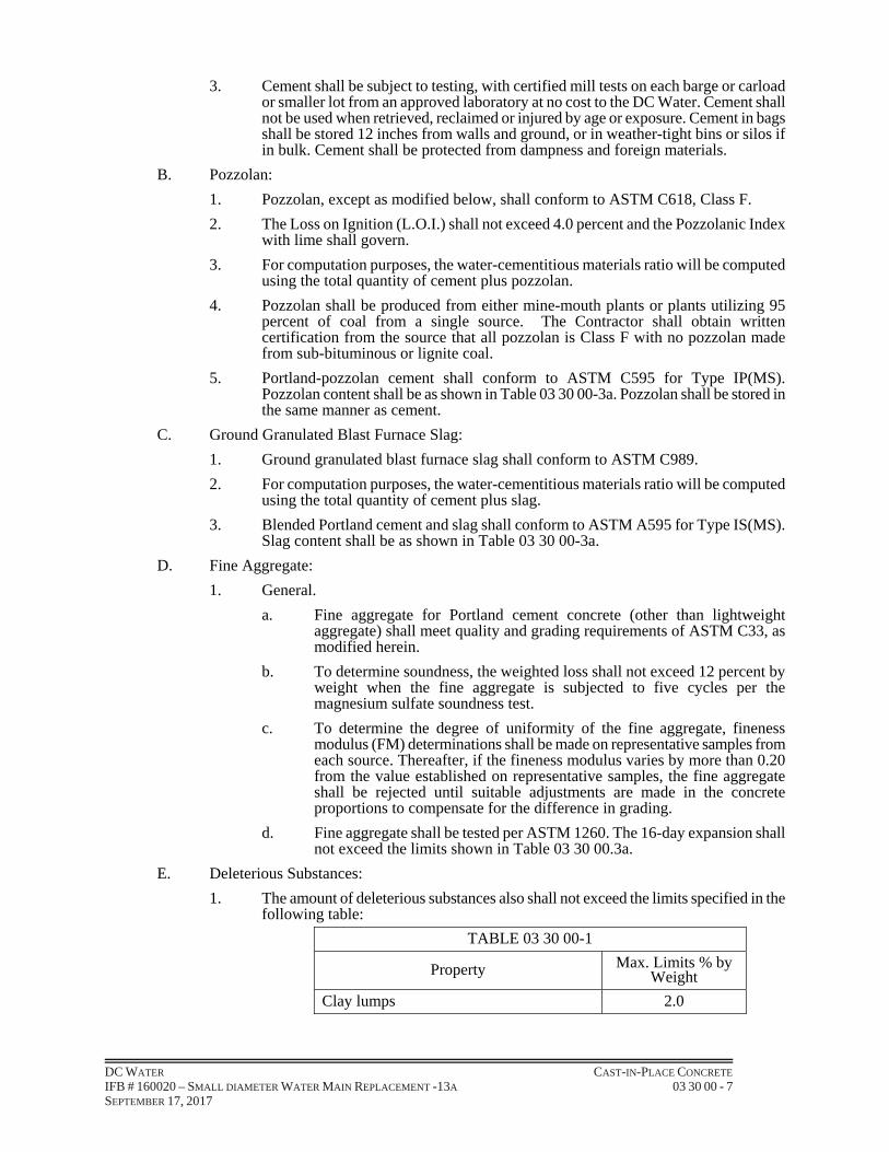
DC WATER CAST-IN-PLACE CONCRETE IFB # 160020 – SMALL DIAMETER WATER MAIN REPLACEMENT -13A 03 30 00 - 7 SEPTEMBER 17, 2017
3. Cement shall be subject to testing, with certified mill tests on each barge or carload or smaller lot from an approved laboratory at no cost to the DC Water. Cement shall not be used when retrieved, reclaimed or injured by age or exposure. Cement in bags shall be stored 12 inches from walls and ground, or in weather-tight bins or silos if in bulk. Cement shall be protected from dampness and foreign materials.
B. Pozzolan:
1. Pozzolan, except as modified below, shall conform to ASTM C618, Class F.
2. The Loss on Ignition (L.O.I.) shall not exceed 4.0 percent and the Pozzolanic Index with lime shall govern.
3. For computation purposes, the water-cementitious materials ratio will be computed using the total quantity of cement plus pozzolan.
4. Pozzolan shall be produced from either mine-mouth plants or plants utilizing 95 percent of coal from a single source. The Contractor shall obtain written certification from the source that all pozzolan is Class F with no pozzolan made from sub-bituminous or lignite coal.
5. Portland-pozzolan cement shall conform to ASTM C595 for Type IP(MS). Pozzolan content shall be as shown in Table 03 30 00-3a. Pozzolan shall be stored in the same manner as cement.
C. Ground Granulated Blast Furnace Slag:
1. Ground granulated blast furnace slag shall conform to ASTM C989.
2. For computation purposes, the water-cementitious materials ratio will be computed using the total quantity of cement plus slag.
3. Blended Portland cement and slag shall conform to ASTM A595 for Type IS(MS). Slag content shall be as shown in Table 03 30 00-3a.
D. Fine Aggregate:
1. General.
a. Fine aggregate for Portland cement concrete (other than lightweight aggregate) shall meet quality and grading requirements of ASTM C33, as modified herein.
b. To determine soundness, the weighted loss shall not exceed 12 percent by weight when the fine aggregate is subjected to five cycles per the magnesium sulfate soundness test.
c. To determine the degree of uniformity of the fine aggregate, fineness modulus (FM) determinations shall be made on representative samples from each source. Thereafter, if the fineness modulus varies by more than 0.20 from the value established on representative samples, the fine aggregate shall be rejected until suitable adjustments are made in the concrete proportions to compensate for the difference in grading.
d. Fine aggregate shall be tested per ASTM 1260. The 16-day expansion shall not exceed the limits shown in Table 03 30 00.3a.
E. Deleterious Substances:
1. The amount of deleterious substances also shall not exceed the limits specified in the following table:
TABLE 03 30 00-1
Property Max. Limits % by Weight
Clay lumps 2.0

DC WATER CAST-IN-PLACE CONCRETE IFB # 160020 – SMALL DIAMETER WATER MAIN REPLACEMENT -13A 03 30 00 - 8 SEPTEMBER 17, 2017
Other deleterious substances (such as shale, mica, coated grains, soft and flaky particles)
1.0
2. Chert, metaquartzite or a combination of both shall not exceed eight percent by weight per ASTM C295. Further examination under other tests not required if content over eight percent.
3. Alkali-silica reactive (ASR) constituents shall not exceed 0.10 percent expansion at sixteen days per ASTM C1260, and will be acceptable only when classified as innocuous per Figure 2, ASTM C289. Fine aggregates having ASR greater than 0.10 but less than 0.20 percent may be used if the Contractor’s concrete mix design is modified as described in paragraph 2.01 I.
4. For alkali-carbonate reactive constituents, test specimen cylinders shall not exceed 0.08 percent expansion after 28 days, immersion in a 1 N NaOH solution per ASTM C586.
F. Organic Impurities: Organic impurities shall produce a color not darker than Organic Plate No. 2 per ASTM C40.
G. Fine Aggregate:
1. Fine aggregate shall be well graded from coarse to fine and when tested by means of laboratory sieves shall conform to the following requirements (per ASTM C33 as modified for percent passing No. 16 sieve) indicated in Table 03 30 00-2:
TABLE 03 30 00-2
Sieve Designation Size % by Weight Passing
3/8 in. 9.50mm 100
No. 4 4.75mm 95-100
No. 8 2.36mm 80-100
No. 16 1.18mm 45-85
No. 30 0.60mm 25-60
No. 50 0.30mm 10-30
No. 100 0.15mm 2-10
H. Coarse Aggregate:
1. General:
a. Except as modified below, coarse aggregate shall meet the quality requirements of ASTM C33 for severe exposure.
b. Coarse aggregate shall consist of trap rock from an approved quarry source, crushed, air cooled blast furnace slag, or other approved inert materials of similar characteristics. Crushed hydraulic cement concrete is prohibited.
c. Aggregates bearing any quantity of asbestos are prohibited. Should such aggregate be utilized, both the Contractor and aggregate supplier will be directed to remove all asbestos bearing aggregates. The Contractor and supplier shall further be liable for all consequential damages that may result as a violation of this requirement.
d. The percentage of abrasion per ASTM C131 shall not exceed 40.
2. Deleterious Substances:
a. The amount of deleterious substances shall not exceed the following limits specified in Table 03 30 00-3:

DC WATER CAST-IN-PLACE CONCRETE IFB # 160020 – SMALL DIAMETER WATER MAIN REPLACEMENT -13A 03 30 00 - 9 SEPTEMBER 17, 2017
TABLE 03 30 00-3
Property Max. Limits % by weight
Soft fragments 2.0
Clay lumps 0.25
Total material finer than No. 200 sieve:
Material containing clay or shale 1.0
Material free of clay or shale 1.5
Thin or elongated pieces (length greater than 5 times the smallest dimension of a circumscribing rectangular prism)
15.0
Sum of clay lumps, friable particles and chart (less than 2.40 Sp. Gr. SSD) 3.0
Other local deleterious substances 2.0
b. Chert, metaquartzite or a combination of both shall not exceed three percent (3%) by weight. Further examination under other tests not required if content over three percent (3%).
c. Alkali-silica reactive (ASR) constituents shall not exceed 0.10 percent expansion at sixteen days per ASTM C1260, and will be acceptable only when classified as innocuous per Figure 2, ASTM C289. Coarse aggregate having ASR between 0.11 and 0.20 percent may be used if the Contractor’s concrete mix design is modified as described in paragraph 2.01 I.
d. For alkali-carbonate reactive constituents, test specimen cylinders shall not exceed 0.08 percent expansion after 28 days, immersion in a 1 N NaOH solution per ASTM C586.
I. Water:
1. Water shall be clean, fresh and free from injurious amounts of oils, acid, alkali, organic matter or other deleterious substances. River and stream water shall not be used.
2. Potable tap water will normally fulfill the above requirements.
J. Admixtures:
1. All concrete, when placed at ambient air temperatures above 75 deg. F, shall have a water reducing and retarding admixture conforming to ASTM C494, Type D. When temperatures are below 75 deg. F, a water reducing admixture shall be used conforming to ASTM C494, Type A. Proportioning and mixing shall be as recommended by the manufacturer.
2. Air-entrainment admixture shall conform to ASTM C260.
3. Admixtures causing accelerated setting of cement in concrete shall not be used.
4. Admixtures shall not contain sugar, calcium chloride or other chlorides. Admixtures shall be stored in a manner so as to prevent contamination, evaporation, or damage.
5. When using admixtures in solution form, the solution quantity shall be included when calculating the water-cement ratio.
K. Concrete: Portland cement, fine aggregate, coarse aggregate, water and admixtures as specified and shall be ready-mixed (transit-mixed) concrete produced per ASTM C94 and as specified herein. All constituents, including admixtures, shall be batched at a central batch plant, except as further specified herein.
L. Reinforced Concrete: Per ACI 301 and as specified herein.
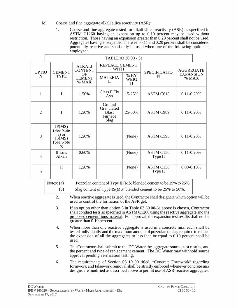
DC WATER CAST-IN-PLACE CONCRETE IFB # 160020 – SMALL DIAMETER WATER MAIN REPLACEMENT -13A 03 30 00 - 10 SEPTEMBER 17, 2017
M. Coarse and fine aggregate alkali silica reactivity (ASR):
1. Coarse and fine aggregate tested for alkali silica reactivity (ASR) as specified in ASTM C1260 having an expansion up to 0.10 percent may be used without restriction. Those having an expansion greater than 0.20 percent shall not be used. Aggregates having an expansion between 0.11 and 0.20 percent shall be considered potentially reactive and shall only be used when one of the following options is employed:
TABLE 03 30 00 - 3a
OPTION
CEMENT TYPE
ALKALI CONTENT
OF CEMENT % MAX
REPLACE CEMENT WITH
SPECIFICATION
AGGREGATE EXPANSION
% MAX MATERIAL
% BY WEIG
H
1 I 1.50% Class F Fly Ash 15-25% ASTM C618 0.11-0.20%
2 I 1.50%
Ground Granulated
Blast Furnace
Slag
25-50% ASTM C989 0.11-0.20%
3
IP(MS) (See Note
a) or IS(MS)
(See Note b)
1.50% (None) ASTM C595 0.11-0.20%
4 II Low Alkali
0.60% (None) ASTM C150 Type II
0.11-0.20%
5 II 1.50% (None) ASTM C150
Type II 0.00-0.10%
Notes: (a) Pozzolan content of Type IP(MS) blended cement to be 15% to 25%.
(b) Slag content of Type IS(MS) blended cement to be 25% to 50%.
2. When reactive aggregate is used, the Contractor shall designate which option will be used to control the formation of the ASR gel.
3. If an option other than option 5 in Table 03 30 00-3a above is chosen, Contractor shall conduct tests as specified in ASTM C1260 using the reactive aggregate and the proposed cementitious material. For approval, the expansion test results shall not be greater than 0.10 percent.
4. When more than one reactive aggregate is used in a concrete mix, each shall be tested individually and the maximum amount of pozzolan or slag required to reduce the expansion of all the aggregates to less than or equal to 0.10 percent shall be used.
5. The Contractor shall submit to the DC Water the aggregate source, test results, and the percent and type of replacement cement. The DC Water may withhold source approval pending verification testing.
6. The requirements of Section 03 10 00 titled, “Concrete Formwork” regarding formwork and falsework removal shall be strictly enforced whenever concrete mix designs are modified as described above to permit use of ASR-reactive aggregates.

DC WATER CAST-IN-PLACE CONCRETE IFB # 160020 – SMALL DIAMETER WATER MAIN REPLACEMENT -13A 03 30 00 - 11 SEPTEMBER 17, 2017
2.2 PRE-PRODUCTION SELECTION OF PROPORTIONS:
A. Prior to production of concrete for the Contract, development of approved mix proportions to produce concrete conforming to these specifications shall be determined either by means of laboratory tested trial mixes or by use of appropriate production facility test records.
1. Trial Mix Proportioning:
a. When a concrete production facility does not have adequate field strength test records, concrete proportions shall be established based on trial mixtures meeting the following restrictions.
1) Trial mixes and tests shall be made by an independent testing laboratory, per ANSI/ASTM E329, experienced in design and testing concrete materials and mixes; the laboratory shall be retained by the Contractor as part of Contract concrete requirements. The Contractor shall submit a report describing proposed concrete testing laboratory, giving qualifications of personnel, laboratory facilities and equipment, evidence of compliance with ANSI/ASTM E329, name and phone number of lab supervisor, and other information as may be requested. Selection of the testing laboratory is subject to the approval of DC Water.
2) Combination of materials and source shall be those proposed for use in the Contract.
3) Trial mixtures having proportions and consistencies suitable for proposed work shall be made using at least three different water-cement ratios that will produce a range of strengths for each class of concrete required, encompassing those required for the Contract.
4) For each Class concrete and each size aggregate required:
a) Mix designed with water reducer.
b) Mix designed with reducer-retarder.
c) Mix designed per a. and b. where required in Contract for use as pumped concrete, per ACI Committee 304R report "Placing Concrete by Pumping Method."
5) Trial mixtures shall be designed to produce a slump within one inch of maximum permitted, and within 0.5 percent of maximum allowable air content. These tolerances apply to trial mixtures only.
6) For each proposed mixture, at least three compressive test cylinders for each age shall be made and cured per ASTM C192. Each change of water-cement ratio shall be considered a new mixture. The cylinders shall be tested for strength per ASTM C39 at 28 days or at a specified earlier or later age.
7) From the results of these cylinder tests, a curve shall be plotted showing the relationship between 28-day compressive strength and the water-cement ratio.
8) From this curve, the water-cement ratio for the concrete to be used in the proposed work shall be selected to meet requirements of, and produce the average compressive strength, f'cr, required by Table 03 30 00-4. The cement content and mixture proportions to be used shall be such that the selected water-cement ratio is not exceeded when slump is the maximum permitted.

DC WATER CAST-IN-PLACE CONCRETE IFB # 160020 – SMALL DIAMETER WATER MAIN REPLACEMENT -13A 03 30 00 - 12 SEPTEMBER 17, 2017
TABLE 03 30 00-4
Class (f'c)
Min Cementitious
Materials (lbs./ cu.yd.)
Coarse Aggregate
Grading (1)
Max. Water (gal./94 lbs. Cement) (2)
Air
(% by vol.)
Req. Avg. 28 Day Lab Test
Cyl. Str. f'cr(psi) (3)
4000 564
517
#67 or 57
#467
5
5.0+1.0 6.0+1.0 5200
3500 564
517
#67 or 57
#467
5-1/2
5.0+1.0 6.0+1.0 4700
3000 564
517
#67 or 57
#467
5-1/2
6
6.0+1.0
5.0+1.0 4200
Notes:
(1) The Contractor may use either Grading Size #57, #67, or #467 grading coarse aggregate as available and as space within forms and pumping requirements will permit.
(2) Maximum; decrease if possible. This represents total water placed in mix at time of mixing, including free unabsorbed water in aggregates and water in admixture solution. Water / cementitious materials ratio shall not exceed 0.44.
(3) Slump = four (4) inches maximum.
B. Production Facility Test Data Proportioning:
1. Concrete proportions may be established and based upon a production facility's field strength test records.
2. Where a concrete production facility has adequate test records, based on at least 30 consecutive strength tests or two groups of tests totaling at least 30 within the past 12 months, the standard deviation shall be calculated; the required average compressive strength, f'cr, calculated; and mixture proportions selected that will produce an average 28 day, compressive strength at least equal to the calculated f'cr.
3. Documentation shall be submitted to the DC Water. If documentation is considered inadequate, the Trial Mix Proportioning method shall be used.
a. Test records from which a standard deviation is calculated shall:
1) Represent materials and materials source, quality control procedures and conditions similar too, those expected for the Contract. Changes in materials and proportions within the test records shall not have been more restricted than those for proposed work.
2) Represent concrete produced to meet a specified strength or strengths f'c within 1000 psi of that specified for proposed work.
3) Consist of test cylinder concrete proportions meeting cement, aggregate, water, and air content requirements of Table 03 30 00-4.
4) Consist of tests made by an independent testing laboratory per ANSI/ASTM E329 experienced in design and testing concrete materials and mixes. The laboratory report of tests shall include information per requirements specified herein.
5) Consist of at least 30 consecutive tests or two groups of consecutive tests totaling at least 30 strength tests.

DC WATER CAST-IN-PLACE CONCRETE IFB # 160020 – SMALL DIAMETER WATER MAIN REPLACEMENT -13A 03 30 00 - 13 SEPTEMBER 17, 2017
b. The standard deviation (psi) shall be determined per ACI 301, subchapter 3.9.1.1(c), using Subsection C.3.a. herein test records.
c. Required average compressive strength, f'cr, used as the basis for selection of concrete proportions shall be the larger of the following two equations using the standard deviation calculated per Subsection C.3.b. above:
f'cr > f'c + 1.34s
or
f'cr > f'c + 2.33s - 500
where
f'c = specified compressive strength of concrete, psi
f'cr = required average compressive strength of concrete, psi
s = standard deviation, psi
d. Documentation that proposed concrete proportions will produce an average strength equal to or greater than the required average strength, f'cr, per formulas above, shall consist of the strength test record, or several strength test records, from existing field tests that also meet Table 03 30 00-4 requirements for cement, aggregate grading, water and air content. Required concrete proportions may be established by interpolation between the strengths and proportions of two or more test records, each of which meets other requirements of this Section.
2.3 MEASURING / MIXING:
A. Materials shall be measured to provide mixes matching the approved design mix(es).
1. Measuring: Materials shall be measured per ASTM C94, Section 8 except as otherwise specified. The apparatus provided for weighing the aggregates and cement shall be suitably designed and constructed for this purpose. Scales shall have been certified by the local Sealer of Weights and Measures within one year of use.
a. Each size of aggregate and the cement shall be weighed separately. The accuracy of all weighing devices shall be such that successive quantities of cement can be measured to within one percent of the desired amount, and aggregate to within two percent. Cement in standard packages (sacks) need not be weighed, but bulk cement and fractional packages shall be weighed.
B. Water:
1. Water shall be measured by volume or by weight. The water measuring device shall be capable of control to one percent accuracy. All measuring devices shall be subject to approval.
2. All wash water shall be dumped before loading drum with concrete materials.
3. No truck shall be loaded which contains free-water in drum unless wash-water quantity is accurately determined beforehand and is accordingly subtracted from total water calculation for the mix.
4. The batch shall be so charged into the mixer that some water will enter in advance of the cement and aggregate, and all water shall be in the drum by the end of the first one-fourth of the specified mixing time.
C. Admixtures: Admixtures shall be dispensed either manually with the use of calibrated containers or measuring tanks, or by means of an approved automatic dispenser designed by the manufacturer of the specific admixture. Admixture dispenser shall be capable of control to 3.0 percent accuracy. Each admixture shall be added separately and with a different portion of the batch loading sequence.
DC WATER CAST-IN-PLACE CONCRETE IFB # 160020 – SMALL DIAMETER WATER MAIN REPLACEMENT -13A 03 30 00 - 14 SEPTEMBER 17, 2017
D. Ready-Mix Concrete: Concrete shall be ready-mixed (transit-mixed per ASTM C94) as produced by equipment acceptable to the DC Water. Concrete shall be mixed at mixing speed for at least 70 and not more than 100 revolutions immediately after charging the drum, followed by agitation without interruption until discharged per ASTM C94. No hand mixing will be permitted. Adding water in controlled amounts during the mixing cycle shall be done only with the express approval of, and under the direction of, the DC Water, and then only if the maximum water-cement ratio is not exceeded.
E. Ready-Mix Concrete Transport:
1. Ready-mix (transit-mixed) concrete meeting approved design mix (es) shall be transported to the site in watertight agitator or mixer trucks loaded not in excess of rated capacities for the respective conditions as stated on the nameplate.
2. Dispatch trucks from the batching plant so that they arrive at the site of the work within the plant just before the concrete is required, thus avoiding excessive agitating of concrete while waiting, or delay in placing successive layers of concrete in the forms.
3. Discharge at the site shall be within 1-1/2 hours after cement was first introduced into the mix; where ambient temperature is above 85 ° F, concrete shall be discharged within one hour.
4. Concrete not discharged within specified time shall be removed from the plant site and not used, and no payment will be made.
F. Re-tempering of Concrete: The re-tempering of concrete which has partially hardened will not be permitted. All concrete shall be discharged completely before drum is recharged.
G. Delivery Tickets:
1. Concrete delivered without a proper delivery ticket will be rejected. The delivery ticket shall show:
a. Name and location of batch plant.
b. Ticket number.
c. Load number.
d. Date and truck number.
e. Destination (name and location of Contract).
f. Type and brand of cement.
g. Concrete class and whether reducer-retarder in mix.
h. Actual quantities of all dry materials, including admixtures.
i. Water content (including free moisture in the aggregate plus water in the drum, exclusive of absorbed moisture in the aggregate) in gallons or pounds per cubic yard of concrete.
j. Volume of concrete (cubic yards).
k. Time mixer drum was charged with cement.
l. For, transit mixed concrete, the recording of revolution counter.
m. Space for initials of receiving party, time of truck arrival at work site, time of actual concrete placement in the formwork and field-measured slump and air content.
2.4 PRODUCTION CONCRETE FIELD TESTS:
A. General:

DC WATER CAST-IN-PLACE CONCRETE IFB # 160020 – SMALL DIAMETER WATER MAIN REPLACEMENT -13A 03 30 00 - 15 SEPTEMBER 17, 2017
1. Conformity of production concrete and concrete materials of this Specification and the actual proportions of cement, aggregates, and water necessary to produce concrete conforming to requirements of Table 03 30 00-4, will be determined by tests made with representative samples of the materials to be used in the work.
2. Tests will be made by the Contractor’s Professional Testing Laboratory (approved by the DC Water) using the following test procedures:
a. Check of aggregates per ASTM C33.
b. Fly ash tests per ASTM C311.
c. Concrete yield per ASTM C138.
d. Air content per ASTM C231 when gravel or stone course aggregate are used and ASTM C173 when slag or other highly porous course aggregates are used.
e. Slump per ASTM C143.
f. Plastic concrete sampled per ASTM C172.
g. Compression and flexure specimens made in the field and cured per ASTM C31.
h. Compressive strength per ASTM C39.
i. Sampling and testing hardened concrete per ASTM C42.
B. Testing Methods: Methods of testing shall conform to the appropriate specification; the place, time, frequency and method of sampling will be determined by the DC Water.
C. Samples: Samples of fine and coarse aggregates shall be furnished by the Contractor for examination and tested at least three weeks before the Contractor proposes to use them in the work and may be retested during the construction period at any time.
D. All concrete testing shall be performed and all reporting provided by an approved testing laboratory at the Contractor’s expense.
E. Testing Criteria: The following criteria establish the required minimum sampling/tests frequency for each class of concrete:
1. Sets of six (6) test cylinder specimens shall be taken at random by the Contractor’s approved testing laboratory for strength test and must be cast to provide three (3) cylinders for laboratory curing and three (3) cylinders for field curing and tested on the same date.
2. Samples for strength tests of each class of concrete placed each day will be taken not less than once a day, nor less than once for each 150 cubic yards of concrete nor less than once for each 5,000 square feet of surface area for slabs or walls (including both sides of wall).
3. On, a given project, if total volume of concrete is such that frequency of testing required above would provide less than five strength tests for a given class of concrete, tests will be made from at least five randomly selected batches or from each batch if fewer than five batches are used.
4. Samples of Portland Cement and aggregates will be taken by the Contractor at random as directed by the DC Water.
5. When total quantity of a given class of concrete for the project is less than 25 cubic yards, strength tests may be waived by the DC Water, if the Contractor provides written evidence of satisfactory materials, quantities and strength.
6. A strength test shall be the average of the strengths of two cylinders made from the same sample of concrete and tested at 28 days for determination of f'c. Test one cylinder at seven days and two cylinders at twenty-eight days.

DC WATER CAST-IN-PLACE CONCRETE IFB # 160020 – SMALL DIAMETER WATER MAIN REPLACEMENT -13A 03 30 00 - 16 SEPTEMBER 17, 2017
7. Air Content: ASTM C231; one test for each set of compressive strength specimens, and additional tests when required by the DC Water.
8. Concrete Temperature: Test hourly when air temperature is 40 degrees F and below, and when 80 degrees F and above, and each time a set of compression test specimens is made.
F. Slump Tests:
1. Slump tests will be made in the field. A slump test shall be made for each truck. Slump shall be measured at the point of delivery into forms. If slump exceeds the values shown in Table 03 30 00-5, the required slump may be obtained by reducing the amount of water shown in the approved proportions. If slump is less than the desired value at first discharge from the mixing drum, water may be added one time only, but only up to the maximum water specified in Table 03 30 00-4, with the approval of the DC Water, to increase the slump to within the specified limits; water shall be incorporated into the mix by further mixing equal to at least one-half the number of mix revolutions for normal mixing. Further addition of water is prohibited.
TABLE 03 30 00-5
Portion of Structure Max. Slump
Footings, caissons, substructure walls 3-in.
Slabs, beams, reinforced walls, columns 4-in.
G. Concrete Cylinders:
1. Cylinders for concrete strength tests shall be molded per ASTM C31 and lab cured per ASTM C31, Section entitled “Curing Cylinders for Checking the Adequacy of Laboratory Mixture Proportions for Strength or as the Basis for Acceptance or for Quality Control”. Specimens shall be cured per ASTM C31. All test cylinders shall be “standard” size, 6-inch diameter x 12-inch long.
2. Strength Requirements: Strength level of an individual class of concrete shall be considered satisfactory if both, of the following requirements are met:
a. Average of all sets of three consecutive strength tests equal or exceed f'c.
b. No individual strength test (average of two cylinders) falls below f'c by more than 500 psi.
3. If the first requirement is not met, steps shall be taken to increase the average of subsequent strength test results. If the second requirement is not met, the DC Water will determine whether the concrete already placed must be tested further or be removed and replaced, or whether it can remain, with the Contractor granting an appropriate credit to the DC Water.
H. Field Cured Cylinders:
1. Field cured cylinder strength tests are required to check the adequacy of curing and protection of concrete in the structure(s).
2. Field-cured cylinders shall be cured under field conditions per ASTM C31 section entitled "Curing Cylinders for Determining Form Removal Time or When a Structure May Be Put into Service.” Specimens shall be cured strictly per ASTM C31. Contractor shall provide a shed or blanket as necessary for field curing in accordance with ASTM C31.
3. Field-cured test cylinders shall be molded at the same time and from the same samples as lab-cured test cylinders.
4. Procedures for protecting and curing concrete shall be improved when strength of field-cured cylinders at test age designated for determination of f'c is less than 85 percent of that of companion lab-cured cylinders. The 85 percent may be waived if field-cured strength exceeds f'c by more than 500 psi.
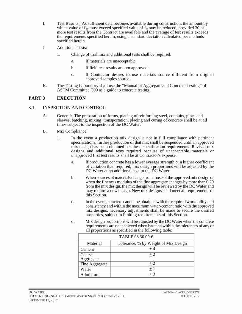
DC WATER CAST-IN-PLACE CONCRETE IFB # 160020 – SMALL DIAMETER WATER MAIN REPLACEMENT -13A 03 30 00 - 17 SEPTEMBER 17, 2017
I. Test Results: As sufficient data becomes available during construction, the amount by which value of f'cr must exceed specified value of f'c may be reduced, provided 30 or more test results from the Contract are available and the average of test results exceeds the requirements specified herein, using a standard deviation calculated per methods specified herein.
J. Additional Tests:
1. Change of trial mix and additional tests shall be required:
a. If materials are unacceptable.
b. If field test results are not approved.
c. If Contractor desires to use materials source different from original approved samples source.
K. The Testing Laboratory shall use the “Manual of Aggregate and Concrete Testing” of ASTM Committee C09 as a guide to concrete testing.
PART 3 EXECUTION
3.1 INSPECTION AND CONTROL:
A. General: The preparation of forms, placing of reinforcing steel, conduits, pipes and sleeves, batching, mixing, transportation, placing and curing of concrete shall be at all times subject to the inspection of the DC Water.
B. Mix Compliance:
1. In the event a production mix design is not in full compliance with pertinent specifications, further production of that mix shall be suspended until an approved mix design has been obtained per these specification requirements. Revised mix designs and additional tests required because of unacceptable materials or unapproved first test results shall be at Contractor's expense.
a. If production concrete has a lower average strength or a higher coefficient of variation than required, mix design proportions will be adjusted by the DC Water at no additional cost to the DC Water.
b. When sources of materials change from those of the approved mix design or when the fineness modulus of the fine aggregate changes by more than 0.20 from the mix design, the mix design will be reviewed by the DC Water and may require a new design. New mix designs shall meet all requirements of this Section.
c. In the event, concrete cannot be obtained with the required workability and consistency and within the maximum water-cement ratio with the approved mix designs, necessary adjustments shall be made to secure the desired properties, subject to limiting requirements of this Section.
d. Mix design proportions will be adjusted by the DC Water when the concrete requirements are not achieved when batched within the tolerances of any or all proportions as specified in the following table:
TABLE 03 30 00-6
Material Tolerance, % by Weight of Mix Design
Cement + 4
Coarse Aggregate
+ 2
Fine Aggregate + 2Water + 1Admixture + 3

DC WATER CAST-IN-PLACE CONCRETE IFB # 160020 – SMALL DIAMETER WATER MAIN REPLACEMENT -13A 03 30 00 - 18 SEPTEMBER 17, 2017
C. Concrete Placement: No concrete shall be ordered or placed until all formwork, reinforcing steel, anchor bolts and other items to be incorporated in the concrete structure have been placed complete, inspected and approved.
D. Notification to Proceed: The Contractor shall advise his testing laboratory and the DC Water of his readiness to proceed at least 20 hours prior to each concrete placement. The DC Water will inspect the preparations for concreting including the preparation of previously placed concrete, the reinforcing and the alignment, and tightness of formwork.
E. Core Samples: In addition to core samples described in Article 3.05 to verify low-strength test cylinder specimens (and which shall be made at the Contractor’s expense), the DC Water may take cores from any questionable area in the concrete work such as construction joints and other locations as required for determination of concrete and construction quality. The results of tests of such cores shall be the basis for acceptance, rejection, or determining the continuation of concrete work.
F. The Contractor shall cooperate in the obtaining of cores by the DC Water by allowing free access to the work and permitting the use of ladders, scaffolding and such incidental equipment as may be required. The Contractor shall repair all core holes to the satisfaction of the DC Water at no additional cost to the DC Water. Cutting and testing the cores will be at the expense of the DC Water unless work is found to be defective, then the Contractor shall assume all costs of obtaining the cores and patching core holes.
3.2 FORMS:
A. Formwork shall be as specified in the "Concrete Formwork" section.
B. Forms shall be used for all concrete work, including footings, and comply with ACI 347R. Forms shall be so constructed and placed that the resulting concrete will be of the shape, lines, dimensions, appearance, and to the elevations indicated on the drawings. Forms constructed and erected shall conform to the shapes, lines and dimensions to tolerances per ACI 117. Forms shall be fabricated in sections as large as practicable.
3.3 PLACING AND CONSOLIDATING:
A. Notification: The DC Water shall be notified at least 20 hours prior to proposed placement of any concrete. Unless otherwise permitted, the work begun on any day shall be complete, including surface finishing and curing materials, in daylight of the same day.
B. Concrete Temperature:
1. Concrete shall have a minimum temperature of 50 deg. F and a maximum temperature of 90 deg. F when placed; concrete at a discharge temperature over 90 deg. F will be rejected. In warm weather, cement temperature at delivery to mixer shall not exceed 170 deg. F. When placing concrete at ambient air temperatures over 75 deg. F, a mix designed with reducer-retarder shall be used. When ambient air temperatures are below 45 deg. F, the mix temperature shall not exceed 70 deg. F.
2. Mixing and placing operations shall be discontinued when a descending ambient air temperature in the shade and away from artificial heat approaches 35 deg. F; operations shall not resume until the temperature reaches 35 deg. F unless aggregate and/or mixing water are heated.
3. If concrete mixing and placing is authorized during ambient air temperatures near or below 35 deg. F, the Contractor shall use proper heating equipment maintained in operable condition to heat the aggregates and/or mixing water to at least 70 deg. F, but not over 150 deg. F. Aggregates shall be heated uniformly, prior to placing in mixer, by steam (only if not by direct discharge into aggregate pile), dry heat or other approved closed system. Heating equipment and methods, which overheat, alter or prevent air entrainment, or prevent proper aggregate discharge from bins, are prohibited.

DC WATER CAST-IN-PLACE CONCRETE IFB # 160020 – SMALL DIAMETER WATER MAIN REPLACEMENT -13A 03 30 00 - 19 SEPTEMBER 17, 2017
C. Inspection and Approval:
1. Place no concrete until reinforcing steel, pipes, anchors, and other work required to be built into concrete have been inspected and approved by the DC Water. Remove water and foreign matter from forms and excavation. Place no concrete on frozen soil, and provide adequate protection against frost action during freezing weather. All base courses for slabs and footings shall be approved by the DC Water before placing concrete.
2. Place no concrete until technicians from the Contractor’s testing laboratory are on-site and prepared for the concrete testing. Contractor shall be responsible for assuring that sufficient testing laboratory technicians and materials are on-site to match the size and duration of each concrete placement, and the number of concrete truck discharge locations.
D. Walls, Columns, Slabs:
1. All concrete walls, slabs and beams shall be built to minimize the effects of shrinkage.
2. At least two hours shall elapse after depositing concrete in walls and columns before depositing concrete in adjacent beams or slabs.
E. Joints:
1. For joints see the Concrete Accessories section. "Cold joints" shall be avoided, but if they occur, shall be treated as bonded construction joints.
2. At construction joints, the surfaces of the concrete already placed, including vertical and inclined surfaces, shall be thoroughly cleaned of foreign materials, laitance and weak concrete, and roughened with suitable tools to expose a fresh face.
3. At least two hours before and again shortly before the new concrete is deposited, the joints shall be saturated with water. After glistening water disappears, the joints shall be given a thorough coating of neat cement slurry mixed to the consistency of very heavy paste. The surfaces shall receive a coating at least 1/8-inch thick on vertical surfaces and 1/2-inch thick on horizontal surfaces. New concrete shall be deposited before the neat cement dries.
4. Construction joints in elevated slabs shall be located near the middle of the spans of slabs, beams or girders, unless a beam intersects a girder at this point, in which case the joint in the girders shall be offset a distance equal to twice the width of the beam. In this case, provision shall be made for shear by using inclined reinforcement.
F. Concrete Transport:
1. Transport concrete from mixer to place of final deposit as rapidly as practicable by methods which prevent separation of ingredients and displacement of reinforcement, and which avoid re-handling. Deposit no partially hardened concrete. Concrete shall not be conveyed through pipe made of aluminum or aluminum alloy.
G. Chutes: Chutes for conveying concrete into forms shall be of U-shaped design and sized to insure a continuous flow of concrete. Flat (coal) chutes or aluminum chutes are prohibited. Chutes shall be metal or metal-lined and each section shall have approximately the same slope. Chutes shall be inclined not flatter than 1 on 3 nor greater than 1 on 2 and shall be such as to prevent the segregation of the ingredients. The discharge end of the chute shall be provided with a baffle plate or snout to prevent segregation. If the discharge end of the chute is more than four feet above the surface of the concrete in the forms, a spout shall be used, and the lower end maintained as near the surface of deposit as practicable. When the operation is intermittent, the chute shall discharge into a hopper. Chutes shall be thoroughly cleaned before and after each run, and the debris and any water shall be discharged outside the forms. Concrete shall not be allowed to flow horizontally over a distance exceeding five feet.
H. Placement of Concrete: Concrete shall be deposited continuously in vertical layers of approximately 12 to 18 inches’ thickness for walls so that concrete will not be deposited

DC WATER CAST-IN-PLACE CONCRETE IFB # 160020 – SMALL DIAMETER WATER MAIN REPLACEMENT -13A 03 30 00 - 20 SEPTEMBER 17, 2017
on concrete which has hardened sufficiently to cause the formation of seams, cold joints or planes of weakness within the section. If a section cannot be placed continuously, construction joints may be located at points as indicated on the Contract Drawings or approved by the DC Water.
I. Concrete Consistency:
1. Consistency of the concrete as measured at point of delivery into forms per ASTM C143 shall be as shown in Table 03 30 00-5.
a. Concrete shall be of such consistency and mix composition that it can be readily worked into the corners and angles of the forms and around the reinforcement, inserts, and wall castings without permitting materials to segregate or free water to collect on the surface, due consideration being given to the methods of placing and compacting.
b. No excessive slump concrete will be permitted, and if at any time concrete of such consistency beyond the limits of Table 03 30 00-5 is delivered to the job, the DC Water may direct the Contractor to reject same or to add extra cement for which no additional payment will be made. A supply of approved cement shall be kept available at the site, and suitably stored, for this purpose. No additional water shall be added by drivers of truck mixers more than the established design. Failure to comply with this requirement shall be justification for rejecting the concrete, unless otherwise approved and as directed by DC Water.
J. Concrete Consolidation:
1. Promptly after depositing concrete in forms, it shall be properly consolidated per ACI 309R by means of suitable tools and methods. Internal-type mechanical vibrators shall be employed in all areas where space permits. Rodding and tamping will be allowed to consolidate concrete around embedded materials. Spading will be allowed only when approved by the DC Water. Consolidation shall be done by experienced operators under close supervision and shall be carried on long enough to produce homogeneity and optimum consolidation without permitting segregation of the solid constituents or "pumping" or migration of air. All vibrator consolidation shall be supplemented by proper wooden spade puddling adjacent to forms to remove included bubbles and honeycomb. All vibrators shall conform to ACI 309R and shall provide not less than 7,000 impulses per minute.
2. At least one vibrator shall be used for every ten cubic yards of concrete placed per hour.
3. In addition, one spare vibrator in operating condition shall be available on the site. Vibrators shall be inserted at uniformly spaced points not more than twice the radius over which vibrations are visibly effective, but not more than three feet apart. Vibrators shall be lowered vertically into the concrete (not thrown in) and allowed to descend by gravity, avoiding forms and reinforcement. Vibrators shall be manipulated so as to thoroughly work concrete into corners, around reinforcing steel and inserts with a five second minimum and 15 second maximum vibration time per each location; they shall not be used to transport concrete laterally. When mortar paste first appears near the top of the vibrator head, the vibrator shall be completely withdrawn vertically at about the same rate it descended.
K. Incomplete Consolidation: Incomplete consolidation (indicated by honeycomb and voids) and over vibration (indicated by flushing of mortar and/or water to surface) is prohibited and may require concrete removal and replacement at the Contractor's expense.
L. Manhole Steps: Manhole steps shall be cast-in-place fitted into precast inserts or fitted into drilled holes. Before press fitting steps into inserts or drilled holes, concrete must have attained 2500 psi minimum field strength.
M. Removal of Forms: Forms shall be removed as specified in the “Concrete Formwork” Section 03 10 00.
DC WATER CAST-IN-PLACE CONCRETE IFB # 160020 – SMALL DIAMETER WATER MAIN REPLACEMENT -13A 03 30 00 - 21 SEPTEMBER 17, 2017
3.4 CURING AND PROTECTION:
A. General: Protect all concrete work against injury from the elements and defacements of any nature during construction operation per ACI 308R.
B. Water: Water shall not be permitted to rise on concrete within 24 hours after placement. Running water over concrete is prohibited within four days of placement.
C. Curing:
1. All concrete, particularly exposed surface’s, shall be treated immediately after concreting or cement finishing is completed to provide continuous moist curing above 50 deg. F for at least the first seven days, regardless of the ambient air temperature. Concrete surfaces may be covered with wet burlap thoroughly saturated with water prior to placement and maintained in a constant saturated condition with a sprinkler system for the first 24 hours when ambient air temperatures are above 90 F.
2. Wet burlap shall not be used when ambient air temperatures are below 35 deg. F or are descending and expected to go below 35 deg. F.
3. Polyethylene and burlap-polyethylene may be used in lieu of wet burlap. Burlap-polyethylene shall be placed with burlap side down and in such a manner as to obtain intimate contact with concrete surfaces and edges. Polyethylene and burlap-polyethylene shall conform to ASTM C171.
4. Concrete used in thrust blocks shall cure a minimum of 4 days prior to backfilling.
D. Use of Liquid Membrane: Sprayed liquid membrane-forming compound may be allowed if approved by the DC Water. The liquid membrane curing compound shall be free of wax and shall contain fugitive dye when used for concrete paving work including sidewalk, curb and gutter. Curing compound shall be applied to wet concrete surfaces in two applications at a rate of at least one gallon per 300 square feet, per application. Curing compound shall not be used when the ambient air temperature during placement and for 24 hours after placement is, or will fall below 35 deg. F. Curing compound shall not be used on concrete surfaces which will receive future grout, grout fill or coatings. Liquid membrane curing compound, if used, shall conform to ASTM C309, Type 1-D.
E. Additional Curing: In continuous cold weather below 32 deg. F., supplementary continuous warm curing (above 50 deg. F.) shall be provided for an additional 350-day degrees (e.g. 5 days at 70 deg. F, etc.) of curing.
F. Protection: No salt, manure or chemicals shall be used for protection. Finished surfaces and slabs shall be protected from the direct rays of the sun to prevent checking and crazing.
G. Special care shall be taken not to deform, damage or displace water stops when concrete is placed against them.
3.5 FIELD QUALITY CONTROL:
A. General:
1. All sampling and testing for field quality control shall be performed during the placement of the concrete by the Contractor’s Certified Testing Laboratory as specified. The testing laboratory shall submit certified copies of the results of each test.
2. The Contractor shall be responsible for notification of the testing laboratory of all concrete placement schedules, and for assuring that sufficient testing personnel and test materials/equipment/supplies are on-site during each scheduled concrete placement.
3. Should the strengths shown by the test specimens made and tested per provisions herein fall below the values given in Table 03 30 00-4 and as specified herein, the
DC WATER CAST-IN-PLACE CONCRETE IFB # 160020 – SMALL DIAMETER WATER MAIN REPLACEMENT -13A 03 30 00 - 22 SEPTEMBER 17, 2017
Contractor shall make changes in source of supply and/or proportions as approved by the DC Water.
4. The Contractor shall remove and replace those portions of the concrete structure which fail to develop the required strength. The cost of all such core borings and/or load tests and concrete (and reinforcing steel, if necessary) removal and replacement, required because strengths of test specimens are below that specified, shall be entirely at Contractor expense.
5. In case of failure to meet 28-day strength requirements, the Contractor shall make the concrete and/or structure satisfactory to the DC Water at no additional cost to the DC Water.
B. Check Tests: When tests on control specimens of concrete fall below the required strength, the DC Water will permit check tests for strength to be made by means of typical cores drilled from the structure per ASTM C42 and C39. In case of failure of the latter per paragraph 17.3.2 of ACI 301, the DC Water may require load tests at Contractor expense. Load tests shall not be made until concrete has aged 60-days.
3.6 REPAIR/RESTORATION:
A. General: It is the intent of these Specifications to require forms, mixture of concrete and workmanship so that concrete surfaces, when exposed, will require no patching.
B. Repair of Forms and Concrete: As soon as the forms have been stripped and the concrete surface exposed, fins and other projections shall be removed, recesses left by the removal of form ties shall be filled, and surface defects which do not impair structural strength shall be repaired. All exposed concrete surfaces and adjoining work stained by leakage of concrete shall be cleaned to provide approved appearance.
C. Tie Holes:
1. Immediately after removal of forms, plugs and break-off metal ties shall be removed and holes moistened with water, followed with a 1/16-inch brush coat of neat cement slurry mixed to the consistency of a heavy paste. Each hole shall then be immediately plugged with a 1:2 mixture of cement and concrete sand mixed slightly damp to the touch (just short of "balling"), hammered into the hole until dense, and an excess of paste appears on the surface in the form of a spider-web. The area shall then be troweled smooth with heavy pressure and warm-moist cured.
2. Burnishing shall be avoided. Grout over 30 minutes old and re-tempered grout shall not be used.
D. Repair Materials:
1. When, patching or repairing exposed surfaces, the same source of cement and sand as used in the parent concrete shall be employed. Color may be adjusted if necessary by addition of proper amounts of white cement. Area shall be rubbed lightly with a fine carborundum stone at an age of one to five days if necessary to bring the surface down with the parent concrete.
2. Care shall be exercised to avoid damaging or staining the virgin skin of the surrounding parent concrete. Area shall be washed thoroughly to remove all accumulations.
E. Repair of Defective Concrete:
1. Defective concrete and honeycomb areas as determined by the DC Water shall be chipped down reasonably square and at least one inch deep to sound concrete by means of hand chisels or pneumatic chipping hammers. Irregular voids or surface stones need not be removed if they are sound, free or laitance, and firmly embedded in the parent concrete, subject to the DC Water’s final inspection. The remaining sound concrete in the defective area shall be roughened. If honeycomb exists around reinforcement, the area shall be chipped to provide a clear space at least 3/8-inch wide all around the steel. For, areas less than 1-1/2, inch deep, the patch may be

DC WATER CAST-IN-PLACE CONCRETE IFB # 160020 – SMALL DIAMETER WATER MAIN REPLACEMENT -13A 03 30 00 - 23 SEPTEMBER 17, 2017
made in the same manner as described above for filling form tie holes, care being exercised to use adequately dry (non-trowelable) mixtures and to avoid sagging.
2. Thicker repairs will require build-up in successive 1-1/2 inch layers on successive days, each layer being applied (with slurry, etc.) as described above. To aid strength and bonding of multiple layer repairs, the DC Water may order the use of an approved non-shrink, non-metallic grout as recommended by the manufacturer.
3. For larger defects, the Contractor shall cut back the area to sound concrete and replace the removed area using the materials and methods of this specification, if directed by the DC Water. The Contractor shall partially or totally remove and rebuild the defective area at no additional expense to the DC Water, using the materials and methods herein specified.
3.7 EPOXY BONDING OF CONCRETE:
A. Epoxy bonding of new concrete or new grout to existing concrete is specifically indicated on the Drawings where required.
1. Cleaning and Preparation:
a. Existing surfaces of previously placed concrete to be bonded shall be thoroughly cleaned of all foreign materials and laitance.
b. Existing concrete surfaces shall be roughened with suitable tools and methods such as wire brushes, picks, wet sand blasting, or other approved method. Surfaces shall be roughened so that the aggregate is slightly exposed over 90 percent of the area.
c. After roughening, surfaces shall be recleaned with either a stream of water or clean compressed air.
d. The roughened/cleaned concrete surfaces shall be saturated with clean water. Pools shall be subsequently removed by clean air jet.
B. Epoxy Bonding:
1. The prepared concrete surfaces shall be coated with an epoxy bonding compound per manufacturer's recommendations.
a. Epoxy bonding compound shall be Concresive 1001-LPL made by Structa-Bond, Inc., Rockville, Md.; DuralBond made by Dural International Corp., Deer Park, N.Y.; Meta Bond HM made by American Metaseal Company, Carlstadt, N.J.; or approved equivalent.
b. The compound shall be a two (2) component epoxy resin system, with 100 percent reactive components and 100 percent solids.
c. The compound shall be new and shall be used within the shelf life, pot life, contact time and temperature limitations marked on each container.
C. New Concrete Epoxy Bonding: New concrete shall be deposited per these specifications and bonded to the epoxy compound after the compound has been cured per the manufacturer's recommendations.
3.8 CONCRETE FINISHES:
A. General: Concrete for the project shall be finished in the various specified manners either to remain as natural concrete or to receive an additional applied finish or material under another section.
B. Finish Types:
1. Finishes shall be as follows:
a. Concrete to receive waterproofing - off-form finish.

DC WATER CAST-IN-PLACE CONCRETE IFB # 160020 – SMALL DIAMETER WATER MAIN REPLACEMENT -13A 03 30 00 - 24 SEPTEMBER 17, 2017
b. Concrete for top slab of junction chambers and floor - wood float finish, non-slip.
c. Concrete over which sanitary or storm water sewage flows - steel troweled finish.
d. Concrete not exposed to view and not scheduled to receive an additional applied finish or material - off-form finish.
e. Concrete interior of culvert walls and arches exposed to storm water flow-smooth form finish.
f. Concrete above grade or exposed and not receiving additional finish on vertical surfaces - rubbed finish.
PART 4 MEASUREMENT AND PAYMENT
4.1 CAST-IN-PLACE CONCRETE:
A. Measurement:
1. Work for Cast-In-Place Concrete will not be measured separately for payment.
B. Payment:
1. No separate payment will be made for work under this Section. Payment for Cast-In-Place Concrete shall be considered incidental and included in the payment for the item of which it is a part of in the SOP’s (item description), which price and payment shall include but not be limited to manhole base slab w/channel, trench excavation, backfill and compaction, disposal of unsuitable excavated material, shoring, sheeting and bracing, trench plating as needed, traffic maintenance & protection, minor complication and/or delays including excavation beyond the trench excavation limits; forming, temporary pavement, seeding and all labor, materials, tools, equipment and incidentals necessary to complete the work as specified within this Contract.
~ END OF SECTION 03 30 00 ~

DC WATER CONCRETE FINISHING IFB # 160020 – SMALL DIAMETER WATER MAIN REPLACEMENT -13A 03 35 00 - 1 SEPTEMBER 17, 2017
SECTION 03 35 00
CONCRETE FINISHING
PART 1 GENERAL
1.1 SUMMARY:
A. Furnish all labor, materials, equipment and incidentals required to perform the Concrete Finishing work as shown on the Contract Drawings and as specified herein.
1.2 RELATED DOCUMENTS:
A. Drawings, Technical Specification Sections, General and Supplementary Conditions of the Contract and other Division 00 and Division 01 Specification Sections, apply to this Section.
B. Specifications throughout all Divisions of the Project Manual are directly pertinent to this Section, and this Section is directly pertinent to them.
1.3 RELATED SECTIONS: Specified elsewhere may include but are not limited to:
A. Section 01 33 00: Submittals
B. Section 03 30 00: Cast-in-Place Concrete
C. Section 03 39 00: Concrete Curing
D. Section 03 40 00: Precast Concrete
1.4 REFERENCE STANDARDS:
A. American Concrete Institute (ACI):
1. ACI 301: “ACI Specifications for Structural Concrete for Buildings”.
2. ACI 306: “ACI Recommended Practice for Cold Weather Concreting”.
3. ACI 605: “ACI Recommended Practice for Hot Weather Concreting”.
B. American Society for Testing and Materials (ASTM):
1. ASTM E1155: “Standard Test Method for Determining FF Floor Flatness and FL Floor Levelness Numbers”.
1.5 QUALITY ASSURANCE:
A. Concrete Work: Concrete work where indicated to be exposed is architecturally finished concrete; special care must be taken to provide specified, finished surfaces without gravel pockets, and other defacements. DC Water shall inspect concrete after removal of forms and before concrete repair work begins.
1.6 PROTECTION:
A. Protect persons and adjacent materials and finishes from dust, dirt and other surface or physical damage during finishing operations, including materials driven by wind.
PART 2 PRODUCTS
(NOT USED)

DC WATER CONCRETE FINISHING IFB # 160020 – SMALL DIAMETER WATER MAIN REPLACEMENT -13A 03 35 00 - 2 SEPTEMBER 17, 2017
PART 3 EXECUTION
3.1 REPAIRS:
A. Immediately after removal of forms and inspect all surfaces for defects. Repair or patch defects only after defects are inspected by the DC Water and then only with the DC Water’s permission. Do all cutting and repair within 48 hours after removal of forms; cure repairs same as new concrete.
B. Defective Areas: Where patches are allowed, repair and patch areas; must match the surrounding areas in color and texture so as, to be indistinguishable after completion, including curing and finishing. Determine mix for color by trial mixes before patching; after initial cure, dress patch or repair area mechanically or by hand for texture match.
3.2 FINISHES FOR FORMED SURFACES:
A. Rough Form Finish: Provide for surface of walls and footings adjacent to grade or below grade. This is the concrete surface having texture imparted by form facing material use with tie holes and defective areas repaired and patched and fins and other projections exceeding 1/4 inch in height rubbed down or chipped off.
B. Smooth Formed Finish: Provide a smooth formed finish on formed concrete surfaces exposed to view. This is an as-cast concrete surface obtained with selected form facing material, arranged in an orderly and symmetrical manner with a minimum of seams. Remove fins and other projections completely and smoothed. Repair and patch honeycombs and defective areas as directed by the DC Water. Tie holes shall not be filled.
C. Sacked Finish:
1. On all designated surfaces of the exposed concrete, provide a sacked finish by coating the concrete with sacking mortar. Sacking of patched or defective concrete surfaces may be required by the DC Water for areas not otherwise already requiring this work.
2. Repair and patch tie holes, honeycombs and defective areas and trowel to smooth finish. Remove fins and other projections completely and smoothed.
3. Thoroughly wet surface to prevent absorption.
4. Coat entire surface with sacking mortar as soon as surface of concrete approaches surface dryness.
5. Thoroughly and vigorously rub mortar over area with clean burlap pads to fill all voids.
6. While mortar is still plastic but partially set (so it cannot be pulled from voids), sack-rub surface with dry mix of sacking mortar (leave out water). There shall be no discernible thickness of mortar on concrete surface, except in voids; all surfaces should be uniformly textured.
7. Immediately begin a continuous moist cure for 72 hours.
D. Related Unformed Surfaces: At tops of walls, horizontal offsets, and similar unformed surfaces adjacent to formed surfaces, strike off smooth and finish with a texture matching adjacent formed surfaces. Continue final surface treatment of formed surfaces uniformly across adjacent unformed surfaces unless otherwise indicated. Provide for face surface of walls adjacent to plaza, walks and stairs.
3.3 FINISHES FOR UNFORMED SURFACES:
A. Screed all slabs, for whatever finish, to true levels or slopes, work surfaces only to the degree required to produce the desired finish; do no finishing in areas where water has accumulated, drain and rescued; in no case use cement and sand sprinkling to absorb

DC WATER CONCRETE FINISHING IFB # 160020 – SMALL DIAMETER WATER MAIN REPLACEMENT -13A 03 35 00 - 3 SEPTEMBER 17, 2017
moisture. Carefully finish all joints and edges with proper tools, unless otherwise specified.
B. Rough Screed Finish: Consolidate, level, and screed all surfaces to obtain evenness and uniformity; remove all surplus concrete after consolidation by striking off with sawing motion against guide strips. Provide for top horizontal surfaces of non-exposed footings. Provide for concrete slab under synthetic safety surfacing.
C. Float Finish: Apply float finish to monolithic slabs to receive trowel or other finishes. After screening, consolidating, and leveling concrete slabs, do not work surface until ready for floating. Begin floating, using float blades or float shoes only, when surface water has disappeared, or when concrete has stiffened sufficiently to permit operation of power-driven floats, or both. Consolidate surface with power driven floats or by hand floating if area is small or inaccessible to power units. Finish surfaces to tolerances of F (F) 18 (floor flatness) and F (L) 15 (floor levelness) measured accordance to ASTM E1155. Cut down high spots and fill low spots. Uniformly slope surfaces to drains. Immediately after leveling, re-float surface to a uniform, smooth, granular texture.
D. Broom Finish: Apply a non-slip broom finish to all exterior concrete slabs, stairs, walks, and ramps, and elsewhere as indicated. Immediately after float finishing, slightly roughen concrete surface by brooming with fiber bristle broom perpendicular to main traffic route.
E. Defective Work: Remove and replace when directed by the DC Water, surfaces which show excessive shrinkage cracks.
3.4 CURING:
A. Protect freshly deposited concrete from premature drying and excessively hot or cold temperatures; maintain minimal moisture loss at relatively constant temperature for necessary hydration time and proper relatively constant temperature for necessary hydration time and proper hardening of concrete.
B. Duration of Curing: In addition to the initial overnight curing, continue final curing operations until the cumulative number of days or fractions thereof (not necessarily consecutive) occurs, during which time the temperature of the air in contact with the concrete is above 50 degrees F, equals seven (7) days. If high-early strength concrete has been used, continue final curing operation for three (3) days total time, calculated as before. Take care to prevent rapid drying at the end of the curing period.
3.5 INSPECTION:
A. Contractor shall notify DC Water that they are starting concrete finish repair work at least 48 hours prior to the beginning of work.
3.6 CLEANING:
A. Leave premises clean and free of residue from work in this section.
PART 4 MEASUREMENT AND PAYMENT
4.1 CONCRETE FINISHING:
A. Measurement:
1. Work for Concrete Finishing shall not be measured separately for payment.
DC WATER CONCRETE FINISHING IFB # 160020 – SMALL DIAMETER WATER MAIN REPLACEMENT -13A 03 35 00 - 4 SEPTEMBER 17, 2017
B. Payment:
1. No separate payment will be made for work under this Section. Payment for Concrete Finishing shall be considered incidental and included under the item of which it is a part of in the SOP’s, which price and payment shall include but not be limited to minor complications and/or delays, traffic maintenance and protection and all labor, materials, tools, fees and equipment necessary to complete the work as specified within this Contract.
~ END OF SECTION 03 35 00 ~

DC WATER CONCRETE CURING IFB # 160020 – SMALL DIAMETER WATER MAIN REPLACEMENT -13A 03 39 00 - 1 SEPTEMBER 17, 2017
SECTION 03 39 00
CONCRETE CURING
PART 1 GENERAL
1.1 SUMMARY:
A. Initial and final curing of horizontal and vertical concrete surfaces.
1.2 RELATED DOCUMENTS:
A. Drawings, Technical Specification Sections, General and Supplementary Conditions of the Contract and other Division 00 and Division 01 Specification Sections, apply to this Section.
B. Specifications throughout all Divisions of the Project Manual are directly pertinent to this Section, and this Section is directly pertinent to them.
1.3 RELATED SECTIONS: Specified elsewhere may include but are not limited to:
A. Section 01 33 00: Submittals B. Section 03 30 00: Cast-in-Place Concrete C. Section 03 35 00: Concrete Finishing D. Section 03 40 00: Precast Concrete
1.4 REFERENCES CODES:
A. American Concrete Institute (ACI): 1. ACI 301: “Structural Concrete for Buildings”. 2. ACI 302: “Recommended Practice for Concrete Floor and Slab Construction. 3. ACI 308: “Standard Practice for Curing Concrete.
B. American Society for Testing and Materials (ASTM): 1. ASTM C171: “Sheet Materials for Curing Concrete”. 2. ASTM C309: “Liquid Membrane ─Forming Compounds for Curing Concrete”. 3. ASTM D2103: “Polyethylene Film and Sheeting”.
1.5 SUBMITTALS:
A. Requirements for “Submittals” shall be in accordance to Section 01 33 00. B. Submit “Product Data Sheets” of each product used. C. Submit a proposed list of sources of all material. Sources shall be approved by the
jurisdiction DOT where the project is being performed and shall include a copy of their certification of each source.
D. Submit the “Test Results” for Concrete Curing. E. Submit the “Field Inspection Data” for Concrete Curing.
1.6 QUALITY ASSURANCE:
A. Perform Work in accordance with ACI 301, ACI 302 and ACI 308.
B. Maintain one set of each of Contract Documents (project manual) and Contract Drawings on site.
PART 2 PRODUCTS
2.1 MATERIALS:
A. Membrane Curing Compound Type (A): ASTM C309, Type 1, Class A, dissipating resin type, translucent with fugitive dye; and/or manufactured recommended.
B. Polyethelene Film Type D: ASTM C171, and/or ASTM D2103, 4 and/or 6 mil 0.15 mm thick, clear.

DC WATER CONCRETE CURING IFB # 160020 – SMALL DIAMETER WATER MAIN REPLACEMENT -13A 03 39 00 - 2 SEPTEMBER 17, 2017
C. Water: Potable and not detrimental to concrete.
PART 3 EXECUTION
3.1 EXAMINATION:
A. Verify that substrate surfaces are ready to be cured and approved by DC Water.
3.2 HORIZONTAL SURFACES & VERTICAL SURFACES:
A. Polyethylene Film: Spread polyethelene film over floor slab areas, lapping edges and sides and sealing with pressure sensitive tape in accordance with manufacturer's instructions.
B. Membrane Curing Compound: Apply curing compound in accordance with manufacturer's instructions.
3.3 PROTECTION OF FINISHED WORK:
A. Requirements for “Concrete finishing” shall be in accordance to Section 03 35 00. B. Do not permit traffic over unprotected ground surface.
PART 4 MEASUREMENT AND PAYMENT
4.1 CONCRETE CURING:
A. Measurement: 1. Work for Concrete Curing shall not be measured separately for payment.
B. Payment: 1. No separate payment will be made for work under this Section. Payment for
Concrete Curing shall be considered incidental and included under the item of which it is a part of in the SOP’s, which price and payment shall include but not be limited to minor complications and/or delays, traffic maintenance and protection and all labor, materials, tools, fees and equipment necessary to complete the work as specified within this Contract.
~ END OF SECTION 03 39 00 ~

DC WATER NON-SHRINK GROUT IFB # 160020 – SMALL DIAMETER WATER MAIN REPLACEMENT -13A 03 62 00 - 1 SEPTEMBER 17, 2017
SECTION 03 62 00
NON-SHRINK GROUT
PART 1 GENERAL
1.1 SUMMARY:
A. Furnish all labor, materials, equipment and incidentals required to perform the grouting work as shown on the standard detail drawings and as specified herein.
1.2 RELATED DOCUMENTS:
A. Drawings, Technical Specification Sections, General and Supplementary Conditions of the Contract and other Division 00 and Division 01 Specification Sections, apply to this Section.
B. Specifications throughout all Divisions of the Project Manual are directly pertinent to this Section, and this Section is directly pertinent to them.
1.3 RELATED SECTIONS: Specified elsewhere may include but are not limited to:
A. Section 01 33 00: Submittals
B. Section 03 25 00: Concrete Accessories
C. Section 03 29 00: Concrete Joints
D. Section 03 30 00: Cast-In-Place Concrete
E. Section 03 35 00: Concrete Finishing
F. Section 03 40 00: Precast Concrete Products
1.4 REFERENCE CODES:
A. American Society for Testing and Materials (ASTM):
1. ASTM C109: “Compressive Strength of Hydraulic Cement Mortars”.
2. ASTM C191: “Time of Setting Hydraulic Cement by Vicat Needle”.
3. ASTM C827: “Change in Height at Early Ages of Cylindrical Specimens of Cementitious Mixtures”.
B. United States Army Core of Engineers (USACE):
1. USACE CRD C621: “Non-Shrink Grout”.
1.5 SUBMITTALS:
A. Requirements for “Submittals” shall be in accordance to Section 01 33 00.
B. Submit “Product Data Sheets” of each product used.
C. Submit the “Instructions” for the application of Non-Shrink Grout.
D. Submit the “Test Results” for Non-Shrink Grout.
E. Submit the “Field Inspection Data” for Non-Shrink Grout.
1.6 QUALITY ASSURANCE:
A. Acceptable Manufacturers:
1. U. S. Grout Corporation.

DC WATER NON-SHRINK GROUT IFB # 160020 – SMALL DIAMETER WATER MAIN REPLACEMENT -13A 03 62 00 - 2 SEPTEMBER 17, 2017
2. Master Builders.
3. USM Corporation.
4. W. R. Meadows.
5. Sonneborn-Contech.
1.7 PRODUCT DELIVERY, STORAGE AND HANDLING:
A. Grout shall be delivered in moisture proof bags with the manufacturer's name, product name and general instructions for placement printed on the bag.
B. Product shall be stored on pallets and protected from damage.
PART 2 PRODUCTS
2.1 MATERIALS:
A. All grout shall be non-metallic, non-shrink, non-gas forming, preblended and ready-for-use requiring only the addition of water.
1. Grout shall contain no metals nor rust or corrosion promoting agents, or gypsums.
2. The addition of set control agents or water reducers will not be allowed.
3. Grout shall conform to the following properties:
Property Test Methods Requirements
Shrinkage below ASTM C827 0
Placement Volume
Drying Shrinkage USACE CRD C621 0
Expansion USACE CRD C621 0.10% max.
Compressive Strength*
24 hours ASTM C109 3000 psi min.
7 days 6000 psi min.
Initial Set Time ASTM C191 Min. 45 minutes
Pull-Out Strength #5 bar grouted 10,000 lbs 6" deep in a 7/8" dia. hole in saturated surface dried concrete
B. Water shall be clean and free from injurious chemicals and deleterious materials.
PART 3 EXECUTION
3.1 CONSTRUCTION REQUIREMENTS:
A. Preparation:
1. All contact surfaces shall be prepared in accordance with manufacturer's recommendations.
2. Grout contact surfaces shall be cleaned of all oil, grease, scale and other foreign matter.
3. Unsound concrete shall be removed leaving surface level but rough.

DC WATER NON-SHRINK GROUT IFB # 160020 – SMALL DIAMETER WATER MAIN REPLACEMENT -13A 03 62 00 - 3 SEPTEMBER 17, 2017
4. Concrete contact area shall be saturated with water 12-24 hours prior to grouting. Before placing grout, remove all excess or freestanding water.
B. Mixing:
1. Grout shall be mixed in strict accordance with the manufacturer's written instructions. Amount of water used should be a minimum quantity to provide the desired grout consistency.
2. Mix only that quantity of grout that can be placed within 30 minutes after mixing.
C. Grouting:
1. All work shall be done in strict accordance with the manufacturer's recommendations, including special procedures for hot and cold weather grouting.
2. Bring the manufacturer’s representative to the job site for consultation regarding detailed use of the grout when directed by DC Water.
3. The grout shall be placed using the most practical method, completely filling the space to be grouted and shall be thoroughly compacted and free of air pockets.
4. Do not remove forms until after the grout has taken an initial set and will not slump. After removal, cut off excess grout and finish to a smooth surface.
5. Prevent rapid loss of water from the grout during first 48 hours with the use of an approved membrane-curing compound, or with the wetted burlap method.
PART 4 MEAUREMENT AND PAYMENT
4.1 NON-SHRINK GROUT:
A. Measurement:
1. Work for Non-Shrink Grout will not be measured separately for payment.
B. Payment:
1. No separate payment will be made for work under this Section. Payment for Non-Shrink Grout shall be considered incidental and included under the item of which it is a part of in the SOP’s, which price and payment shall include but not be limited to minor complications and/or delays, traffic maintenance and protection and all labor, materials, tools, fees and equipment necessary to complete the work as specified within this Contract.
~ END OF SECTION 03 62 00 ~
DC WATER NON-SHRINK GROUT IFB # 160020 – SMALL DIAMETER WATER MAIN REPLACEMENT -13A 03 62 00 - 4 SEPTEMBER 17, 2017
THIS PAGE IS INTENTIONALLY LEFT BLANK