section 1 - distributor of industrial & mining plugs ... · section 1. your tool for finding...
TRANSCRIPT

Multi-axis controller
Double-handle controller Single-axis
controller
Control switch
Standard contact-arrangement Ordering
information Technical data
Section 1

Your tool for finding industrial controllers for cranes, electro-hy-draulic systems, floor conveyors, industrial applications, ships, rail vehicles, and construction machinery of any kind, joysticks and masterswitches with electronic interface adjustment for all machines matching our product portfolio. Take advantage of our fold-out order tool on this page and the detailed tables of contents at the beginning of each position.
Tool for Designers, Engineers and Purchasing Agents
Product range
1Multi-axis controller
Double-handle controller
Single-axis controller
Control switch
Standard contact-arrangement
Ordering information
Technical data

Product Portfolio
Multi-axis controller, double-handle controller, control switch (master-switch), gear limit switch for hoisting, electro-hydraulic application, material-handling technology and remote control
Geared limit switch for joisting equipment
Complete crane control unit, portable control unit, pendant control unit, including wiring for all types of cranes, vehicles and industrial applications
Operating panels for construction machinery, industrial applications, vehicles and harvesting machines
Control pedestals, ship-operating transmitters, sensor units and actual-value transmitters for ship drives
Pedal controllers for welding machines, road and rail vehicles
Master controllers, panels and control stations for rail vehicles
Displays for forklifts and construction machinery
Proportional control electronics for solenoid valves
Interface electronics with digital and analog outputs matching our controllers
Interface electronics with Profibus interface or CAN-bus interface matching our controllers (input/output cards)
DC controllers, selector switches (signal controllers) for high-voltage systems
Customized solutions for operating devices and electronic units for any type of machinery and vehicles
Gessmann is an international market leader. Our success in the market is based upon our decisive focus on innovative product development and the highest possible standards when it comes to quality. Our product range includes:
Management certification:

Contents
Multi-axis controller V6 / VV6 S. 1-5
V11 S. 6-9
V8 / VV8 S. 10-13
V85 / VV85 S. 14-22
V24 S. 23-26
V25 S. 27-32
V14 S. 33-36
V20 S. 37-38
V22 S. 39-40
V23 S. 41-42
V21 S. 43-44
Double-handle controller D64 / DD64 S. 45-49
D8 S. 50-53
D85 S. 54-59
D3 S. 60-64
Single-axis controller S1 S. 65-67
S11 S. 68-71
S14 S. 72-74
S2 / SS 2 / S21 S. 75-79
S22 / SS22 S. 80-83
S23 S. 84-86
S26 S. 87-90
S27 S. 91-94
S3 S. 95-98
S9 S. 99-100
Control switch N6 S. 101-103
N9 S. 104-105
Standard contact-arrangement S. 106-107
Ordering information S. 108-112
Technical data S. 113-114
Potentiometer S. 115
HG 1 S. 116-117
OEC 2 S. 118-120
OEC 4 S. 121
Electronic control unit S. 122-123
MATRIX grip S. 124
Hall-push button S. 125-127
Palm grip B1 S. 128-129
B2 S. 130-131
B3 S. 132-134
B5 S. 135-136
B6 S. 137-138
B7 / B8 S. 139-140
B9 S. 141-142
B10 S. 143-144
B14 / B15 S. 145-146
B20 S. 147-148
B22 S. 149-150
B23 S. 151-152
B24 S. 153-154
B25 S. 155-156
B28 S. 157-158
B29 S. 159-160
Housing S. 161-162
Crane control unit KST 4 S. 163-165
KST 5 S. 166-168
KST 6 S. 169-171
KST 7 / KST 75 S. 172-174
KST 8 S. 175-177
KST 85 S. 178-179
KST 10 S. 180-182
KST 19 S. 183-185
Driver seat KFS 2 S. 186-187
KFS 4 S. 188-189
KFS 82 S. 190-191
KFS 9 S. 192-193
KFS 10 S. 194-195
KFS 11 S. 196-197
KFS 12 S. 198-199
Portable control unit TS 1 S. 200-202
TS 2 S. 203-205
Control pedestal for offshore U 22/32 S. 206-208
U 23/23 S. 209-211
Naval cruise controller AZ 1 S. 212-213
Pedal-controller P7 / PP7 S. 214-215
P8 / PP8 S. 216-217
P10 / P11 / P12 S. 218-219
Gear limit switch GE 1/2 S. 220-222
DC-contact SO / SS S. 223-224
Signal-cam controller NU 1 S. 225-227

1
Multi-axis controller V6 / VV6
page 1
Technical details may vary based on configuration or application! Technical data subject to change without notice!
The multi-axis controller V6 / VV6 is available in either single-axis or multi-axis options and is a robust controller used commonly in electro-hydraulic applications. The modular design and many possibilities of combination with our handles enables the switching device to be used universally. The V6 / VV6 is resistant to oil, maritime conditions e.g. offshore / vessels, UV radiation typically from the sun.
Technical data
Mechanical life V6 10 million operating cycles
Mechanical life VV6 20 million operating cycles
Operation temperature -40°C til +60°C
Degree of protection IP 54 front
Example
V62L S5 P T - 01 Z P + 03A R C - A05 P134 + A110 C01 - X
Basic unit
V62L 2-axis left
Control-handle extended
S5 -20 mm
Gate
P Cross gate
Grip / palm grip
T Dead man
Axis 1 (direction 1-2)
01 2 Contacts (2A 250V AC15)
Z Spring return
P Potentiometer
Axis 2 (direction 3-4)
03A 6 Contacts (4A 250V AC15)
R Friction brake
C Opto-electronical encoder
Describtion axis 1 (direction 1-2)
A05 Arrangement MS 21
P134 Potentiometer T396 2x5 kOhm
Describtion axis 2 (direction 3-4)
A110 Arrangement MS 24-0
C01 OEC 2-1-1
Special model
X Special / customer-specific

1
Multi-axis controller V6 / VV6
Combination possibilities with our ball handles
page 2
V20
15/1
10.
02.2
015
Technical details may vary based on configuration or application! Technical data subject to change without notice!
V62L S5 P T - 01 Z P + 03A R C - A05 P134 + A110 C01 - X
Basic unit
V61L 1-axis left Identification of the installation variants
V61R 1-axis right with switching directions:
V61.1 1-axis
V64.1 1-axis
V62L 2-axis left
V62R 2-axis right
V64 2-axis
reinforced version
VV61L 1-axis left
VV61R 1-axis right
VV61.1 1-axis
VV64.1 1-axis
VV62L 2-axis left
VV62R 2-axis right
VV64 2 axis
Control-handle extended*
Standard 180 mm
S3 -40 mm
S5 -20 mm
S8 +20 mm
*Only available in combination with handle!
Gate
P Cross gate
P X Special gate
Grip / palm grip
Knob (standard)
M Mechanical zero interlock
MN Mechanical zero interlock (push down)
T Dead man
MT* Mechanical zero interlock + dead man
H Signal button
MH Mechanical zero interlock + signal button
D Push button
MD* Mechanical zero interlock + push button
DV Flush push button
MDV* Mechanical zero interlock + flush push button
*Only possible with VV6!
B... Palm grip B... (see Palm grip page 128)
Attention! When using some handles reduces the deflection angle
to 28 degrees!
1
2
1-2
1
21-2
1
2
3 4
3-4
1-2
1
2
1
2
3 4
3-4
5
6
5-6
5
6
7 8
7-8
5-6
V61L/VV61L
V61.1/VV61.1
V62L/VV62L
V64/VV64
V64.1/VV64.1
V61R/VV61R
V62R/VV62R
B1 B3 B5 B6 B10 B14 B15 B22 B24 B28
S. 128 S. 132 S. 135 S. 137 S. 143 S. 145 S. 149 S. 153 S. 157

1
Multi-axis controller V6 / VV6
page 3
Technical details may vary based on configuration or application! Technical data subject to change without notice!
V62L S5 P T - 01 Z P + 03A R C - A05 P134 + A110 C01 - X
Axis 1: direction 1-2 left / direction 5-6 right
(Standard contacts gold-plated 2A 250V AC15)
01 2 contacts Standard contact - arrangement see page 106
02 4 contacts z.B.
03 6 contacts A980 MS 00
04 8 contacts A05 MS 21
05 10 contacts A0500 MS 21-00
06 12 contacts A110 MS 24-0
A = silver contacts (4A 250V AC15) A99 contact - arrangement according customer request
Z Spring return
R Friction brake
(P) Possibility of mounting potentiometer and encoder (Gessmann-types)
P Potentiometer P131 T396 2x0,5 kOhm l max. 1 mA
P132 T396 2x1 kOhm l max. 1 mA
P133 T396 2x2 kOhm l max. 1 mA
P134 T396 2x5 kOhm l max. 1 mA
P135 T396 2x10 kOhm l max. 1 mA
More potentiometer on request!
C Encoder C... Encoder see page 118
If both axis identical, it`s enough to describe one axis!
Beispiel A05P134 + A05P134 => A05P134
V62L S5 P T - 01 Z P + 03A R C - A05 P134 + A110 C01 - X
Axis 2: Direction 3-4 left / Direction 7-8 right (not applicable to V/VV61, V/VV61.1, V/VV64.1)
(Standard contacts gold-plated 2A 250V AC15)
01 2 contacts Standard contact - arrangement see page 106
02 4 contacts z.B.
03 6 contacts A980 MS 00
04 8 contacts A05 MS 21
05 10 contacts A0500 MS 21-00
06 12 contacts A110 MS 24-0
A = Silver contacts (4A 250V AC15) A99 contact - arrangement according customer request
Z Spring return
R Friction brake
(P) Possibility of mounting potentiometer and encoder (Gessmann-types)
P Potentiometer P131 T396 2x0,5 kOhm l max. 1 mA
P132 T396 2x1 kOhm l max. 1 mA
P133 T396 2x2 kOhm l max. 1 mA
P134 T396 2x5 kOhm l max. 1 mA
P135 T396 2x10 kOhm l max. 1 mA
More potentiometer on request!
C Encoder C... Encoder see page 118
1
Multi-axis controller V6 / VV6
page 4
V20
15/1
10.
02.2
015
Technical details may vary based on configuration or application! Technical data subject to change without notice!
V62L S5 P T - 01 Z P + 03A R C - A05 P134 + A110 C01 - X
Special model
X Special / customer-specific
Special model
Indicating labels
Indicating labels with engraving

1
Multi-axis controller V6 / VV6
page 5
Technical details may vary based on configuration or application! Technical data subject to change without notice!
T = Dead man's buttonH = Signal buttonM = Latch for mechanical zero interlock
42
Knob solidD= Push button
46
10
77
180
85
40° 40°
A
max
. 4
T MN
H M MP
Cover plate
CAGE CLAMP® connectionmax. 2,5mm²
IP 54
IP 00
96
B
B
30
30
80
80
5,5
72
8030
30
3,5
Hole pattern
PotentiometerT 130
OEC-mounting
203
Palm grip B3
155
Palm grip B5
180
38 Palm grip B1B1 T= Dead man's button
1 / 101
Type No. of contacts Dim. A Dim. B
01 2 119 82
02 4 131 94
03 6 144 107
04 8 156 119
05 10 169 132
06 12 181 144

1
Multi-axis controller V11
page 6
V20
15/1
10.
02.2
015
Technical details may vary based on configuration or application! Technical data subject to change without notice!
The multi-axis controller V11 is a robust switching device for crane and hoisting applications. The modular design enables the switching device to be used universally. The V11 is resistant to oil, maritime conditions e.g. offshore / vessels, UV radiation typically from the sun.
Technical data
Mechanical life 10 million operating cycles
Operation temperature -40°C til +60°C
Degree of protection IP 54 front
V11L S5 P T - 01 Z P + 03A R - A05 P324 + A110 - X
Basic unit
V11L 2-axis left
Control-handle extended
S5 -20 mm
Gate
P Cross gate
Grip / palm grip
T Dead man
Axis 1 (direction 1-2)
01 2 Contacts (2A 250V AC15)
Z Spring return
P Potentiometer
Axis 2 (direction 3-4)
03A 6 Contacts (4A 250V AC15)
R Friction brake
Describtion axis 1 (direction 1-2)
A05 Arrangement MS 21
P324 Potentiometer T365 2x5 kOhm
Describtion axis 2 (direction 3-4)
A110 Arrangement MS 24-0
Special model
X Special / customer-specific
Example
1
Multi-axis controller V11
1
2
1
2
43
page 7
Technical details may vary based on configuration or application! Technical data subject to change without notice!
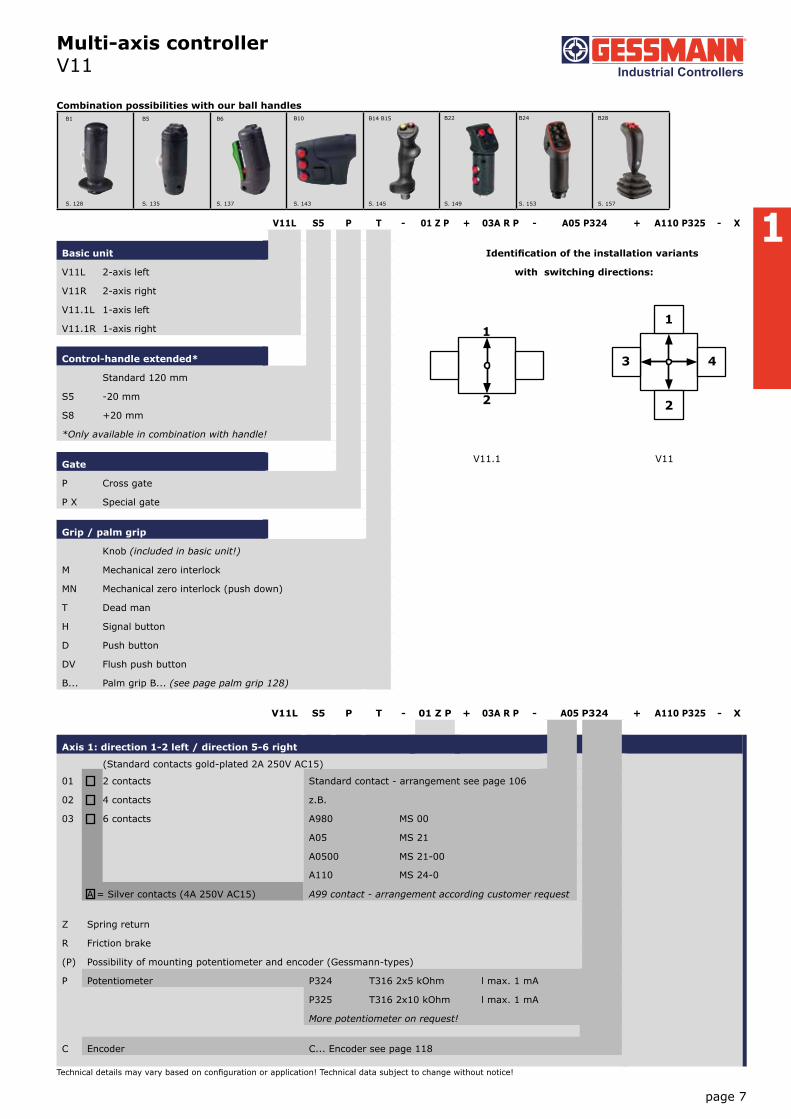
V11L S5 P T - 01 Z P + 03A R P - A05 P324 + A110 P325 - X
Basic unit Identification of the installation variants
V11L 2-axis left with switching directions:
V11R 2-axis right
V11.1L 1-axis left
V11.1R 1-axis right
Control-handle extended*
Standard 120 mm
S5 -20 mm
S8 +20 mm
*Only available in combination with handle!
Gate
P Cross gate
P X Special gate
Grip / palm grip
Knob (included in basic unit!)
M Mechanical zero interlock
MN Mechanical zero interlock (push down)
T Dead man
H Signal button
D Push button
DV Flush push button
B... Palm grip B... (see page palm grip 128)
V11.1 V11
V11L S5 P T - 01 Z P + 03A R P - A05 P324 + A110 P325 - X
Axis 1: direction 1-2 left / direction 5-6 right
(Standard contacts gold-plated 2A 250V AC15)
01 2 contacts Standard contact - arrangement see page 106
02 4 contacts z.B.
03 6 contacts A980 MS 00
A05 MS 21
A0500 MS 21-00
A110 MS 24-0
A = Silver contacts (4A 250V AC15) A99 contact - arrangement according customer request
Z Spring return
R Friction brake
(P) Possibility of mounting potentiometer and encoder (Gessmann-types)
P Potentiometer P324 T316 2x5 kOhm l max. 1 mA
P325 T316 2x10 kOhm l max. 1 mA
More potentiometer on request!
C Encoder C... Encoder see page 118
B1 B5 B6 B10 B14 B15 B22 B24 B28
S. 128 S. 135 S. 137 S. 143 S. 145 S. 149 S. 153 S. 157
Combination possibilities with our ball handles

1
Multi-axis controller V11
page 8
V20
15/1
10.
02.2
015
Technical details may vary based on configuration or application! Technical data subject to change without notice!
If both axis identical, it`s enough to describe one axis!
example: ...A05P324 + A05P324 => A05P324
V11L S5 P T - 01 Z P + 03A R P - A05 P324 + A110 P325 - X
Axis 2: direction 3-4 left / direction 7-8 right (not applicable to V11.1)
(Standard contacts gold-plated 2A 250V AC15)
01 2 contacts (2A 250V AC15) Standard contact - arrangement see page 106
02 4 contacts (2A 250V AC15) z.B.
03 6 contacts (2A 250V AC15) A980 MS 00
A05 MS 21
A0500 MS 21-00
A110 MS 24-0
A = Silver contacts (4A 250V AC15) A99 contact - arrangement according customer request
Z Spring return
R Friction brake
(P) Possibility of mounting potentiometer and encoder (Gessmann-types)
P Potentiometer P324 T365 2x5 kOhm l max. 1 mA
P325 T365 2x10 kOhm l max. 1 mA
More potentiometer on request!
C Encoder C... Encoder see page 118
V11L S5 P T - 01 Z P + 03A R P - A05 P324 + A110 P325 - X
Special model
X Special / customer-specific
Special model
Indicating labels
Indicating labels with engraving

1
Multi-axis controller V11
page 9
Technical details may vary based on configuration or application! Technical data subject to change without notice!
42
Knob solidD= Push button
55
80
max
. 3
120
36° 36°
5
58±
0,1
70
Hole pattern
T = Dead man's buttonH = SignalbuttonM = Latch for mechanical zero interlock T MN
H M MP
CAGE CLAMP® connectionmax. 2,5mm²
Potentiometer T365
Cover plateIP 54
IP 00
38
180
1
35
Palm grip B1
Opto-electronical
encoder OEC 2
B B
B
B
86
70 78 B
78
B
1 / 111
Type No. of contacts Dim. B
01 2 51
02 4 64
03 6 76

1
Multi-axis controller V8 / VV8
page 10
V20
15/1
10.
02.2
015
Technical details may vary based on configuration or application! Technical data subject to change without notice!
The multi-axis controller V8/VV8 is avialable in either single-axis or multi-axis options and is a robust controller used commonly in electro-hydraulic applications. With many output options including voltage, amperage and switch contacts and many handle options the V8 / VV8 series is hugely customisable. The V8 / VV8 is resistant to oil, maritime conditions e.g. offshore / vessels, UV radiation typically from the sun.
Technical data
Mechanical life V8 10 million operating cycles
Mechanical life VV8 20 million operating cycles
Operation temperature -40°C til +60°C
Degree of protection IP 54
VV8 S5 P T - 2RP + 3ZP - B - A05 P184 + A050 P184 E9012 - X
Basic unit
VV8 2-axis, reinforced version
Control-handle extended
Standard
S5 -20 mm
S8 +20 mm
*Only available in combination with handle!
Gate
P Cross gate
P X Special gate
Grip / palm grip
T Dead man
Axis 1
2 2 Contacts
R Friction brake
P Potentiometer
Axis 2
3 Contacts
Z Spring return
P Potentiometer
Cover housing
B Cover housing
Describtion axis 1 (direction 1-2)
A050 Arrangement MSP 21-0
P184 Potentiometer T301 2x5 kOhm
Describtion axis 2 (direction 3-4)
A05 Arrangement MSP 21
P184 Potentiometer T301 2x5 kOhm
Interface (description see on the following pages)
E9012 Potentiometer output for proportional valve PVG32
Special model
X Special / customer-specific
Example

1
Multi-axis controller V8 / VV8
page 11
Technical details may vary based on configuration or application! Technical data subject to change without notice!
VV8 S5 P T - 2 R P + 3 Z P - B - A05 P184 + A050 P184 E9012 - X
Basic unit
V81 1-axis
V8 2-axis
reinforced version
VV81 1-axis
VV8 2-axis
Control-handle extended
S5 -20 mm
S8 +20 mm
Gate
P Cross gate
P X Special gate
Grip/ palm grip
Knob (included in basic unit!)
M Mechanical zero interlock
MH Mechanical zero interlock + signal contact
T Dead man
H Signal button
D Push button
DV Flush push button
B... Palm grip B... (see page palm grip 128)
Axis 1: direction 1-2
1 1 contact Standard contact - arrangement see page 106
2 2 contacts z.B.
3 3 contacts A98 MS 0 Zero position contact
A05 MS 21 Direction contact
A050 MS 21-0 Direction contact + zero position contact
Z Spring return
R Friction brake only possible with VV8!
(P) Mounting options for potentiometer
P Potentiometer P181 T301 2x0,5 kOhm l max. 1 mA
P182 T301 2x1 kOhm l max. 1 mA
P183 T301 2x2 kOhm l max. 1 mA
P184 T301 2x5 kOhm l max. 1 mA
P185 T301 2x10 kOhm l max. 1 mA
More potentiometer on request!
Hall-Potentiometer P43 T1360 0,5...2,5...4,5V/4,5V...2,5...0,5
B1 B2 B3 B5 B6 B7 B8 B9 B10 B14 B15
B20 B22 B23 B24 B25 B28 B29
S. 128 S. 130 S. 132 S. 135 S. 137 S. 139 S. 141 S. 143
S. 147 S. 149 S. 151 S. 153 S. 155 S. 157 S. 159
S. 145
Combination possibilities with our ball handles

1
Multi-axis controller V8 / VV8
page 12
V20
15/1
10.
02.2
015
Technical details may vary based on configuration or application! Technical data subject to change without notice!
If both axis identical, it`s enough to describe one axis!
example: ...A05P43 + A05P43 => A05P43
VV8 S5 P T - 2 R P + 3 Z P - B - A05 P184 + A050 P184 E9012 - X
Axis 2: direction 3-4 (not applicable to V81/VV81)
01 1 contact Standard contact - arrangement see page 106
02 2 contacts z.B.
03 3 contacts A98 MS 0 Zero position contact
A05 MS 21 Direction contact
A050 MS 21-0 Direction contact + zero position contact
Z Spring return
R Friction brake only possible with VV8!
(P) Mounting options for potentiometer
P Potentiometer P181 T301 2x0,5 kOhm l max. 1 mA
P182 T301 2x1 kOhm l max. 1 mA
P183 T301 2x2 kOhm l max. 1 mA
P184 T301 2x5 kOhm l max. 1 mA
P185 T301 2x10 kOhm l max. 1 mA
More potentiometer on request!
Hall-Potentiometer P43 T1360 0,5...2,5...4,5V/4,5V...2,5...0,5
VV8 S5 P T - 2 R P + 3 Z P - B - A05 P184 + A050 P184 E9012 - X
Cover housing
B Cover housing
Interface
Potentiometer output
E901 Potentiometer output for proportional valve PVG32
0,25...0,5...0,75Us
1 1 axis
2 2 axis
3 3 axis
4 4 axis
Special model
X Special / customer-specific

1
Multi-axis controller V8 / VV8
page 13
Technical details may vary based on configuration or application! Technical data subject to change without notice!
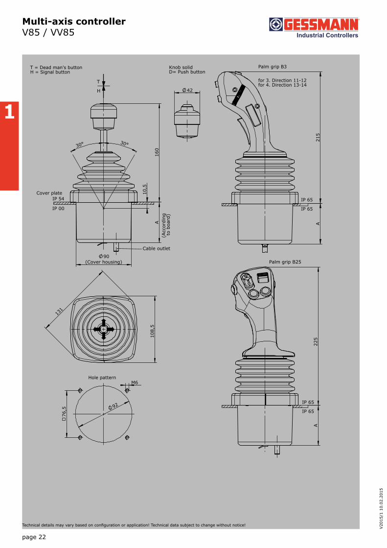
215
IP 65
Palm grip B3
for 3. Direction 11-12for 4. Direction 13-14
1 / 131
IP 65
30° 30°
10,
5
A
90(Cover housing)
160
T = Dead man's buttonH = Signal buttonM = Latch for mechanical zero interlock
T MN
H M MP
IP 54Cover plate
Cable outlet
IP 00
131
108
,5
92
M6
76,5
Hole pattern
225
Palm grip B25
IP 65
IP 65
42
Knob solidD= Push button
(Acc
ordi
ng t
o bo
ard)

1
page 14
V20
15/1
10.
02.2
015
Technical details may vary based on configuration or application! Technical data subject to change without notice!
The multi-axis controller V85/VV85 is available in either single-axis or multi-axis options and is a robust controller used commonly in electro-hydraulic applications. With many output options including voltage, amperage and switching contacts and many handle options the V85/VV85 series is hugly customisable. The V85/VV85 is resistant to oil, maritime conditions e.g. offshore / vessels, UV radiation typically from the sun.
Technical data
Mechanical life V85 10 million operating cycles
Mechanical life VV85 20 million operating cycles
Supply voltage see interface
Operation temperature -40°C til + 60°C
Degree of protection IP 54
Functional safety PLd (EN ISO 13849) possible
VV85 S8 P T - Z + R - B - E... - X
Basic unitV85.1 1-axisV85 2-axis
Reinforced versionVV85.1 1-axisVV85 2-axis
Control-handle extendedStandard 160 mm
S5 -20 mmS8 +20 mm*Only available in combination with handle!
GateP Cross gateP X Special gate
Grip / palm grip Knob (included in basic unit!)Knob with Mechanical zero interlock
T Dead manH Signal buttonD Push buttonB... Palm grip B... (see page palm grip 128)
Axis 1Z Spring returnR Friction brake only possible with VV85!
Axis 2 (not applicable to V/VV85.1)Z Spring returnR Friction brake only possible with VV85!
Cover housingB Cover housing (included in basic unit!)
Interface (description see on the following pages)E0xx Switching outputE1xx Voltage outputE2xx Current outputE3xx CAN-interfaceE4xx CANOpen Safety interfaceE5xx Profibus DP-interfaceE6xx ProfinetE7xx Profinet Safe
Special modelX Special / customer-specific
Multi-axis controller V85 / VV85
Example

1
page 15
Technical details may vary based on configuration or application! Technical data subject to change without notice!
Multi-axis controller V85 / VV85
Digital output
Supply voltage 9-32VDC
Current carrying capacity Direction signal 150 mA
Zero position signal 500 mA
Mounting depth A 85 mm
Wiring Cable 500 mm long with plug connector (pins) CPC 17 - 14-pole
2 Direction signal + 1 zero position signal (galvanically isolated) per axis
1 axis E001 1
2 axis 2
Voltage output (not stabilized)
Supply voltage 4,75-5,25VDC
Current carrying capacity Direction signal 8 mA
Mounting depth A 85 mm
Wiring Cable 500 mm long with plug connector (pins) CPC 17 - 14-pole
Characteristic: 1 = contra rotating, 2 = concurrently rotating
0,5...2,5...4,5V redundant + 2 direction signal per axis
1 axis E104 1
2 axis 2
Voltage output
Supply voltage 9-32VDC (*11,5-32)
Current carrying capacity Direction signal 150 mA
Zero position signal 500 mA
Mounting depth A 85 mm
Wiring Cable 500 mm long with plug connector (pins) CDC 17 - 14-pole
Cable (for axis 3+4 or grip functions) 500 mm long with plug connector (socket) CPC 17 - 14-pole
Characteristic: 1 = contra rotating, 2 = concurrently rotating
0,5...2,5...4,5V redundant + 2 direction signal + 1 zero position signal (galvanically isolated) per axis
1 axis E112 1
2 axis 2
3 axis* 3
4 axis* 4
B1 B2 B3 B5 B6 B7 B8 B9 B10 B14 B15
B20 B22 B23 B24 B25 B28 B29
S. 128 S. 130 S. 132 S. 135 S. 137 S. 139 S. 141 S. 143
S. 147 S. 149 S. 151 S. 153 S. 155 S. 157 S. 159
S. 145
Combination possibilities with our ball handles

1
page 16
V20
15/1
10.
02.2
015
Technical details may vary based on configuration or application! Technical data subject to change without notice!
0...5...10V redundant + 2 direction signal + 1 zero position signal (galvanically isolated) per axis, supply voltage 11,5 - 32VDC
1 axis E132 1
2 axis 2
3 axis* 3
4 axis* 4
10...0...10V redundant + 2 direction signal + 1 zero position signal (galvanically isolated) per axis, supply voltage 11,5 - 32VDC,
sensor redundant, 1 output with signal monitoring
1 axis E136 1
2 axis 2
3 axis* 3
4 axis* 4
Multi-axis controller V85 / VV85
Current output
Supply voltage 9-32VDC
Current carrying capacity Direction signal 150 mA
Zero position signal 500 mA
Mounting depth A 85 mm
Wiring Cable 500 mm long with plug connector (pins) CDC 17 - 14-pole
2. Cable (for axis 3+4 or grip functions) 500 mm long with plug connector (socket) CPC17 - 14-pole
0...10...20 mA redundant + 2 direction signal + 1 zero position signal (galvanically isolated) per axis, sensor redundant,
1 output with signal monitoring
1 axis E206 1
2 axis 2
3 axis* 3
4 axis* 4
20...0...20 mA redundant + 2 direction signal + 1 zero position signal (galvanically isolated) per axis, sensor redundant,
1 output with signal monitoring
1 axis E208 1
2 axis 2
3 axis* 3
4 axis* 4
4...12...20 mA redundant + 2 direction signal + 1 zero position signal (galvanically isolated) per axis, sensor redundant,
1 output with signal monitoring
1 axis E214 1
2 axis 2
3 axis* 3
4 axis* 4
20...4...20 mA redundant + 2 direction signal + 1 zero position signal (galvanically isolated) per axis, sensor redundant,
1 output with signal monitoring
1 axis E216 1
2 axis 2
3 axis* 3
4 axis* 4
*Axis for handel functions, interface can vary depending upon actuation element!
Voltage output with other value on request!

1
page 17
Technical details may vary based on configuration or application! Technical data subject to change without notice!
Multi-axis controller V85 / VV85
CAN Expansion stage 2 E305 1
- 5 analog joystick axis
- 14 digital joystick functions
- Input for capacitive sensor
*external LED-outputs can be used in the grip for LED`s
with additional external in-/outputs
- 4 external LED-outputs, 8 external digital inputs 2
CAN Expansion stage 3 E306 1
- 8 analog joystick axis
- 14 digital joystick functions
- Input for capacitive sensor
*external LED-outputs can be used in the grip for LED`s
with additional external in-/outputs
- 8 external LED-outputs, 8 external digital inputs 2
- 8 external LED-outputs, 16 external digital inputs 3
- 24 external digital inputs 4
- 8 external LED-outputs, 24 external digital inputs 5
CAN Expansion stage 4 E307 1
- 9 analog joystick axis
- 14 digital joystick functions
- 2 inputs für capacitive sensor
*external LED-outputs can be used in the grip for LED`s
with additional external in-/outputs
- 8 external LED-outputs, 8 external digital inputs 2
- 8 external LED-outputs, 16 external digital inputs 3
- 24 external digital inputs 4
- 8 external LED-outputs, 24 external digital inputs 5
with additional signals separately wired (not CAN)
3
CAN Expansion stage 1 E304 1
- 3 analog joystick axis
- 14 digital joystick functions
or 10 digital joystick functions + 4 LED-outputs
CAN
Supply voltage 9-36VDC
Idle current consumption 120 mA
Mounting depth A 85 mm (Expansion stage 1)
85 mm (Expansion stage 2)
85 mm (Expansion stage 3)
100 mm (Expansion stage 4)
Protocol CANopen CiA DS 301 or SAE J 1939
Bautrate 125 kBit/s til 1 Mbit/s
Output value 0...128...255
Wiring CAN (IN) cable 500 mm with plug connector M12 (pins)
CAN (OUT) cable 500 mm with plug connector M12 (socket)
External in-/outputs cable 500 mm with plug connector CPC 23-37 (socket)
1
page 18
V20
15/1
10.
02.2
015
Technical details may vary based on configuration or application! Technical data subject to change without notice!
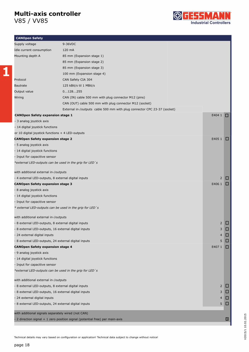
Multi-axis controller V85 / VV85
CANOpen Safety expansion stage 2 E405 1
- 5 analog joystick axis
- 14 digital joystick functions
- Input for capacitive sensor
*external LED-outputs can be used in the grip for LED`s
with additional external in-/outputs
- 4 external LED-outputs, 8 external digital inputs 2
CANOpen Safety expansion stage 3 E406 1
- 8 analog joystick axis
- 14 digital joystick functions
- Input for capacitive sensor
* external LED-outputs can be used in the grip for LED`s
with additional external in-/outputs
- 8 external LED-outputs, 8 external digital inputs 2
- 8 external LED-outputs, 16 external digital inputs 3
- 24 external digital inputs 4
- 8 external LED-outputs, 24 external digital inputs 5
CANOpen Safety expansion stage 4 E407 1
- 9 analog joystick axis
- 14 digital joystick functions
- Input for capacitive sensor
*external LED-outputs can be used in the grip for LED`s
with additional external in-/outputs
- 8 external LED-outputs, 8 external digital inputs 2
- 8 external LED-outputs, 16 external digital inputs 3
- 24 external digital inputs 4
- 8 external LED-outputs, 24 external digital inputs 5
with additional signals separately wired (not CAN)
- 2 direction signal + 1 zero position signal (potential free) per main-axis 3
CANOpen Safety expansion stage 1 E404 1
- 3 analog joystick axis
- 14 digital joystick functions
or 10 digital joystick functions + 4 LED-outputs
CANOpen Safety
Supply voltage 9-36VDC
Idle current consumption 120 mA
Mounting depth A 85 mm (Expansion stage 1)
85 mm (Expansion stage 2)
85 mm (Expansion stage 3)
100 mm (Expansion stage 4)
Protocol CAN Safety CIA 304
Bautrate 125 kBit/s til 1 MBit/s
Output value 0...128...255
Wiring CAN (IN) cable 500 mm with plug connector M12 (pins)
CAN (OUT) cable 500 mm with plug connector M12 (socket)
External in-/outputs cable 500 mm with plug connector CPC 23-37 (socket)

1
page 19
Technical details may vary based on configuration or application! Technical data subject to change without notice!
Multi-axis controller V85 / VV85
Profibus DP E501 1
- 4 analog joystick axis
- 16 digital joystick functions
- Input for capacitive sensor
*external LED-outputs can be used in the grip for LED`s
with additional external in-/outputs
- 8 external LED-outputs, 8 external digital inputs 2
- 16 external LED-outputs, 16 external digital inputs 3
with additional contact equipment separately wired (not profibus)
- 2 direction contact + 1 zero position contact (not potential-free) per main-axis 1
- 1 zero position contact (potential free) per main-axis 2
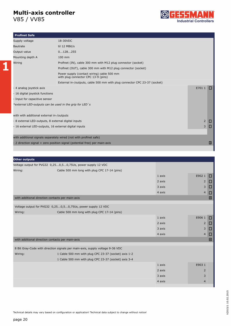
Profinet
Supply voltage 18-30VDC
Bautrate til 12MBit/s
Output value 0...128...255
Mounting depth A 100 mm
Wiring Profinet (IN), cable 300 mm with M12 plug connector (socket)
Profinet (OUT), cable 300 mm with M12 plug connector (socket)
Power supply (contact wiring) cable 500 mm with plug connector CPC 13-9 (pins)
External in-/outputs, cable 500 mm with plug connector CPC 23-37 (socket)
Profinet E601 1
- 4 analog joystick axis
- 16 digital joystick functions
- Input for capacitive sensor
*external LED-outputs can be used in the grip for LED`s
with with additional external in-/outputs
- 8 external LED-outputs, 8 external digital inputs 2
- 16 external LED-outputs, 16 external digital inputs 3
with additional signals separately wired (not with profinet)
- 2 direction signal + zero position signal (potential free) per main-axis 3
Profibus DP
Supply voltage 18-30VDC
Bautrate til 12MBit/s
Output value 0...128...255
Mounting depth A 100 mm
Wiring Profibus, cable 100 mm with plug connector D-Sub 9
Power supply (contact wiring) cable 500 mm with plug connector CPC 13-9 (pins)
external in-/outputs, cable 500 mm with plug connector CPC 23-37 (socket)
1
page 20
V20
15/1
10.
02.2
015
Technical details may vary based on configuration or application! Technical data subject to change without notice!
Multi-axis controller V85 / VV85
Other outputs
Voltage output for PVG32 0,25...0,5...0,75Us, power supply 12 VDC
Wiring: Cable 500 mm long with plug CPC 17-14 (pins)
1 axis E902 1
2 axis 2
3 axis 3
4 axis 4
with additional direction contacts per main-axis 4
Voltage output for PVG32 0,25...0,5...0,75Us, power supply 12 VDC
Wiring: Cable 500 mm long with plug CPC 17-14 (pins)
1 axis E906 1
2 axis 2
3 axis 3
4 axis 4
with additional direction contacts per main-axis 4
8 Bit Gray-Code with direction signals per main-axis, supply voltage 9-36 VDC
Wiring: 1 Cable 500 mm with plug CPC 23-37 (socket) axis 1-2
1 Cable 500 mm with plug CPC 23-37 (socket) axis 3-4
1 axis E903 1
2 axis 2
3 axis 3
4 axis 4
- 4 analog joystick axis E701 1
- 16 digital joystick functions
- Input for capacitive sensor
*external LED-outputs can be used in the grip for LED`s
with with additional external in-/outputs
- 8 external LED-outputs, 8 external digital inputs 2
- 16 external LED-outputs, 16 external digital inputs 3
with additional signals separately wired (not with profinet safe)
- 2 direction signal + zero position signal (potential free) per main-axis 3
Profinet Safe
Supply voltage 18-30VDC
Bautrate til 12 MBit/s
Output value 0...128...255
Mounting depth A 100 mm
Wiring Profinet (IN), cable 300 mm with M12 plug connector (socket)
Profinet (OUT), cable 300 mm with M12 plug connector (socket)
Power supply (contact wiring) cable 500 mm with plug connector CPC 13-9 (pins)
External in-/outputs, cable 500 mm with plug connector CPC 23-37 (socket)

1
page 21
Technical details may vary based on configuration or application! Technical data subject to change without notice!
Multi-axis controller V85 / VV85
8 Bit Binär-Code with direction signals per main-axis, supply voltage 9-36 VDC
Wiring: 1 Cable 500 mm with plug CPC 23-37 (socket) axis 1-2
1 Cable 500 mm with plug CPC 23-37 (socket) axis 3-4
1 axis E904 1
2 axis 2
3 axis 3
4 axis 4
Special model
Mating connector AMP CPC 17 14-pole (male insert) 5300000209
Mating connector AMP CPC 17 14-pole (male insert) with 2 m cable 5300000210
Mating connector AMP CPC 17 14-pole (socket contact) 5300000211
Mating connector AMP CPC 17 14-pole (socket contact) with 2 m cable 5300000213
Mating connector AMP CPC 23 37-pole (male insert) 5300000214
Mating connector AMP CPC 23 37-pole (male insert) with 2 m cable 5300000215
Mating connector AMP CPC 23 37-pole (socket contact) 5300000216
Mating connector AMP CPC 23 37-pole (socket contact) with 2 m cable 5300000217
Mating connector (CAN) M12 (male insert) with 2 m cable 20201140
Mating connector (CAN) M12 (socket contact) with 2 m cable 20202298
Mating connector (Profibus) straight 22201440
Mating connector (Profibus) 90° angled 22201741
Mating connector (Profinet IN) M12 (male insert) with 2 m cable 5300000222
Mating connector (Profinet OUT) M12 (male insert) with 2 m cable 5300000223
1
page 22
V20
15/1
10.
02.2
015
Technical details may vary based on configuration or application! Technical data subject to change without notice!
Multi-axis controller V85 / VV85
A
215
IP 65
IP 65
Palm grip B3
for 3. Direction 11-12for 4. Direction 13-14
1 / 133
180
A
38
90 (Abdeckgehäuse)
IP 54
IP 65
GriffkugelD = Drucktaster
Ballengriff B1
160
30° 30° 1
0,5
A
90(Cover housing)
T
H
IP 54Cover plate
T = Dead man's buttonH = Signal button
Cable outlet
IP 00
131
108
,5
92
M6
76,5
Hole pattern
A
225
Palm grip B25
IP 65
IP 65
42
Knob solidD= Push button
(Acc
ordi
ng
to b
oard
)

1
page 23
Technical details may vary based on configuration or application! Technical data subject to change without notice!
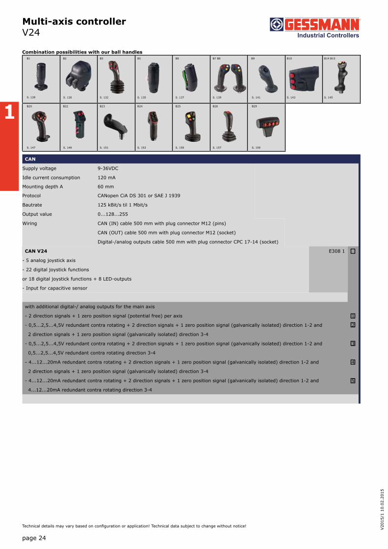
Multi-axis controller V24
The association drive V24 is designed as a driving joystick for construction and agricultural machinery. It has a parking position which can be inserted in the zero position. The V24 is characterized by its extremely rugged design. Through it`s various interfaces and the many possibilities of combination with our numerous ball handles the V24 is very flexible.
Technical data
Mechanical life V24 20 million operating cycles
Supply voltage see interface
Operation temperature -40°C til +60°C
Degree of protection IP 54
Functional safety PLd (EN ISO 13849) possible
V24 P1 T - R - E... - X
Basic unit
V24.1 Multi-axis controller, 1-axis
V24L Multi-axis controller, 1-axis with parking position left
V24R Multi-axis controller, 1-axis parking position right
Gate
P1 T-gate main axis axial (included in basic unit!)
P2 T-gate main axis right outside
P3 T-gate main axis left outside
PX Special gate
Grip / Palm grip
Knob (included in basic unit!)
T Dead man
H Signal button
D Push button
B... Palm grip B... (see page palm grip 128)
Main axis
R Friction brake adjustable (included in basic unit!)
Interface (description see on the following pages)
E3xx CAN-interface
E4xx CANOpen Safety interface
Special model
X Special / customer-specific
Example
1
page 24
V20
15/1
10.
02.2
015
Technical details may vary based on configuration or application! Technical data subject to change without notice!
Multi-axis controller V24
CAN
Supply voltage 9-36VDC
Idle current consumption 120 mA
Mounting depth A 60 mm
Protocol CANopen CiA DS 301 or SAE J 1939
Bautrate 125 kBit/s til 1 Mbit/s
Output value 0...128...255
Wiring CAN (IN) cable 500 mm with plug connector M12 (pins)
CAN (OUT) cable 500 mm with plug connector M12 (socket)
Digital-/analog outputs cable 500 mm with plug connector CPC 17-14 (socket)
CAN V24 E308 1
- 5 analog joystick axis
- 22 digital joystick functions
or 18 digital joystick functions + 8 LED-outputs
- Input for capacitive sensor
with additional digital-/ analog outputs for the main axis
- 2 direction signals + 1 zero position signal (potential free) per axis 1
- 0,5...2,5...4,5V redundant contra rotating + 2 direction signals + 1 zero position signal (galvanically isolated) direction 1-2 and 2
2 direction signals + 1 zero position signal (galvanically isolated) direction 3-4
- 0,5...2,5...4,5V redundant contra rotating + 2 direction signals + 1 zero position signal (galvanically isolated) direction 1-2 and 3
0,5...2,5...4,5V redundant contra rotating direction 3-4
- 4...12...20mA redundant contra rotating + 2 direction signals + 1 zero position signal (galvanically isolated) direction 1-2 and 4
2 direction signals + 1 zero position signal (galvanically isolated) direction 3-4
- 4...12...20mA redundant contra rotating + 2 direction signals + 1 zero position signal (galvanically isolated) direction 1-2 and 5
4...12...20mA redundant contra rotating direction 3-4
B1 B2 B3 B5 B6 B7 B8 B9 B10 B14 B15
B20 B22 B23 B24 B25 B28 B29
S. 128 S. 130
S. 147 S. 149
S. 132 S. 135 S. 137 S. 139 S. 141 S. 143 S. 145
S. 151 S. 153 S. 155 S. 157 S. 159
Combination possibilities with our ball handles

1
page 25
Technical details may vary based on configuration or application! Technical data subject to change without notice!
Multi-axis controller V24
Special model
Mating connector AMP CPC 17 14-pole (male insert) 5300000209
Mating connector AMP CPC 17 14-pole (male insert) with 2 m cable 5300000210
Mating connector (CAN) M12 (male insert) with 2 m cable 20201140
Mating connector (CAN) M12 (socket contact) with 2 m cable 20202298
- 4...12...20mA redundant contra rotating + 2 direction signals + 1 zero position signal (galvanically isolated) direction 1-2 and 4
2 direction signals + 1 zero position signal (galvanically isolated) direction 3-4
- 4...12...20mA redundant contra rotating + 2 direction signals + 1 zero position signal (galvanically isolated) direction 1-2 and 5
4...12...20mA redundant contra rotating direction 3-4
CANOpen Safety
Supply voltage 9-36VDC
Idle current consumption 120 mA
Mounting depth A 60 mm
Protocol CANOpen Safety CIA 304
Bautrate 125 kBit/s til 1 Mbit/s
Output value 0...128...255
Wiring CAN (IN) cable 500 mm with plug connector M12 (pins)
CAN (OUT) cable 500 mm with plug connector M12 (socket)
Digital-/ analog outputs cable 500 mm with plug connector CPC 17-14 (socket)
CANOpen Safety V24 E408 1
- 5 analog joystick axis
- 14 digital joystick functions
or 10 digital joystick functions + 4 LED-outputs
- Input for capacitive sensor
with additional digital-/ analog outputs for the main axis
- 2 direction signals + 1 zero position signal (potential free) per axis 1
- 0,5...2,5...4,5V redundant contra rotating + 2 direction signals + 1 zero position signal (galvanically isolated) direction 1-2 and 2
2 direction signals + 1 zero position signal (galvanically isolated) direction 3-4
- 0,5...2,5...4,5V redundant contra rotating + 2 direction signals + 1 zero position signal (galvanically isolated) direction 1-2 and 3
0,5...2,5...4,5V redundant contra rotating direction 3-4

1
page 26
V20
15/1
10.
02.2
015
Technical details may vary based on configuration or application! Technical data subject to change without notice!
Multi-axis controller V24
60
12,
3
91
15° 15°
IP 54
IP 00
Cover plate
108,5
131
92
M6
76,5
Hole pattern
91
206
25° 25°
1 / V24

1
Multi-axis controller V25
page 27
Technical details may vary based on configuration or application! Technical data subject to change without notice!
The multi-axis controller V25 is available in either single-axis or multi-axis options and is a robust controller used commonly in electro-hydraulic applications. With many output options including voltage, amperage and switching contacts and many handle options the V25 series is hugly customisable. The V25 is resistant to oil, maritime conditions e.g. offshore / vessels, UV radiation typically from the sun.
Technical data
Mechanical life V25 8 million operating cycles
Supply voltage see interface
Operation temperature -40°C til +60°C
Degree of protection IP 54
Functional safety PLd (EN ISO 13849) possible
V25 S8 P T - Z - B - E... - X
Basic unit
V25.1 1-axis
V25 2-axis
Control-handle long
Standard 100 mm
S8 +20 mm
*Only available in combination with handle!
Gate
P Cross gate
Grip / palm grip
Knob (included in basic unit!)
M Mechanical zero interlock
T Knob with dead man
H Knob with signal button
D Knob with push button KDA/70
B ... Palm grip B... (see page palm grip 128)
Spring return (includet in basic unit!)
Z Spring return
Cover housing (description see page 161)
B Cover housing
Interface (description see on the following page)
E0xx Switching output
E1xx Voltage output
E2xx Current output
E3xx CAN-interface
E4xx CANOpen Safety interface
Special model
X Special / customer-specific
Example

1
Multi-axis controller V25
page 28
V20
15/1
10.
02.2
015
Technical details may vary based on configuration or application! Technical data subject to change without notice!
Digital output
Supply voltage 9-32VDC
Current carrying capacity Direction signal 150 mA
Zero position signal 500 mA
Wiring Cable 500 mm long with plug connector (pins) CPC 17 - 14-pole
2 Direction signal + 1 zero position signal (galvanically isolated) per axis
1 axis E001 1
Voltage output (not stabilized)
Supply voltage 4,75-5,25VDC
Current carrying capacity Direction signal 8 mA
Mounting depth A 60 mm
Wiring Cable 500 mm long with plug connector (pins) CPC 17 - 14-pole
Characteristic: 1 = contra rotating, 2 = concurrently rotating
0,5...2,5...4,5V redundant + 2 direction signal per axis
1 axis E104 1
Voltage output
Supply voltage 9-32VDC (*11,5-32V)
Current carrying capacity Direction signal 150 mA
Zero position signal 500 mA
Wiring Cable 500 mm long with plug connector (pins) CPC 17 - 14-pole
Characteristic: 1 = contra rotating, 2 = concurrently rotating
0,5...2,5...4,5V redundant + 2 direction signal + 1 zero position signal (galvanically isolated) per axis
1 axis E112 1
2 axis 2
3 axis* 3
4 axis* 4
0...5...10V redundant + 2 direction signal + 1 zero position signal (galvanically isolated) per axis, supply voltage 11,5 - 32VDC
1 axis E132 1
2 axis 2
3 axis* 3
4 axis* 4
B1 B2 B3 B5 B6 B7 B8 B9 B10 B14 B15
B20 B22 B23 B24 B25 B28 B29
S. 147 S. 149
S. 130 S. 132 S. 135 S. 137 S. 139 S. 141 S. 143 S. 145
S. 151 S. 153 S. 155 S. 157 S. 159
Combination possibilities with our ball handles
S. 128

1
Multi-axis controller V25
page 29
Technical details may vary based on configuration or application! Technical data subject to change without notice!
Current output
Supply voltage 9-32VDC
Current carrying capacity Direction signal 150 mA
Zero position signal 500 mA
Mounting depth A 60 mm
75 mm (from 3 axis)
Wiring Cable 500 mm long with plug connector (pins) CPC 17 - 14-pole
2. cable (for axis 3+4 or grip functions) 500 mm long with plug connector (socket) CPC 17 - 14-pole
0...10...20mA redundant + 2 direction signal + 1 zero position signal (galvanically isolated) per axis, sensor redundant,
1 output with signal monitoring
1 axis E206 1
2 axis 2
3 axis* 3
4 axis* 4
20...0...20mA redundant + 2 direction signal + 1 zero position signal (galvanically isolated) per axis, sensor redundant,
1 output with signal monitoring
1 axis E208 1
2 axis 2
3 axis* 3
4 axis* 4
4...12...20mA redundant + 2 direction signal + 1 zero position signal (galvanically isolated) per axis, sensor redundant,
1 output with signal monitoring
1 axis E214 1
2 axis 2
3 axis* 3
4 axis* 4
20...4...20mA redundant + 2 direction signal + 1 zero position signal (galvanically isolated) per axis, sensor redundant,
1 output with signal monitoring
1 axis E216 1
2 axis 2
3 axis* 3
4 axis* 4
*Axis for grip functions, interfaces may vary depending upon actuation element!
Voltage output with other value on request!
10...0...10V redundant + 2 direction signal + 1 zero position signal (galvanically isolated) per axis, supply voltage 11,5 - 32VDC,
sensor redundant, 1 output with signal monitoring
1 axis E136 1
2 axis 2
3 axis * 3
4 axis * 4
*Axis for grip functions, interfaces may vary depending upon actuation element!
Voltage output with other value on request!
1
Multi-axis controller V25
page 30
V20
15/1
10.
02.2
015
Technical details may vary based on configuration or application! Technical data subject to change without notice!
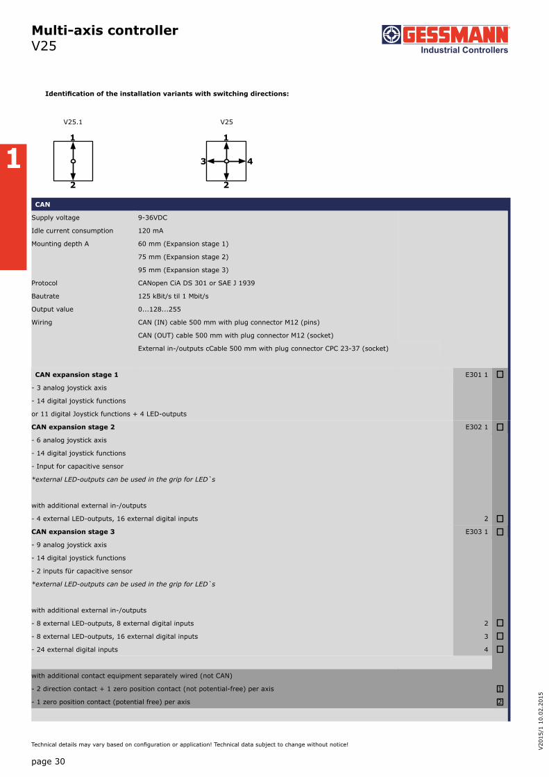
1
2
1
2
3 4
V25.1 V25
Identification of the installation variants with switching directions:
CAN
Supply voltage 9-36VDC
Idle current consumption 120 mA
Mounting depth A 60 mm (Expansion stage 1)
75 mm (Expansion stage 2)
95 mm (Expansion stage 3)
Protocol CANopen CiA DS 301 or SAE J 1939
Bautrate 125 kBit/s til 1 Mbit/s
Output value 0...128...255
Wiring CAN (IN) cable 500 mm with plug connector M12 (pins)
CAN (OUT) cable 500 mm with plug connector M12 (socket)
External in-/outputs cCable 500 mm with plug connector CPC 23-37 (socket)
CAN expansion stage 1 E301 1
- 3 analog joystick axis
- 14 digital joystick functions
or 11 digital Joystick functions + 4 LED-outputs
CAN expansion stage 2 E302 1
- 6 analog joystick axis
- 14 digital joystick functions
- Input for capacitive sensor
*external LED-outputs can be used in the grip for LED`s
with additional external in-/outputs
- 4 external LED-outputs, 16 external digital inputs 2
CAN expansion stage 3 E303 1
- 9 analog joystick axis
- 14 digital joystick functions
- 2 inputs für capacitive sensor
*external LED-outputs can be used in the grip for LED`s
with additional external in-/outputs
- 8 external LED-outputs, 8 external digital inputs 2
- 8 external LED-outputs, 16 external digital inputs 3
- 24 external digital inputs 4
with additional contact equipment separately wired (not CAN)
- 2 direction contact + 1 zero position contact (not potential-free) per axis 1
- 1 zero position contact (potential free) per axis 2

1
Multi-axis controller V25
page 31
Technical details may vary based on configuration or application! Technical data subject to change without notice!
CANOpen Safety expansion stage 3 E403 1
- 9 analog joystick axis
- 14 digital joystick functions
- 2 inputs for capacitive sensor
*external LED-outputs can be used in the grip for LED`s
with additional external in-/outputs
- 8 external LED-outputs, 8 external digital inputs 2
- 8 external LED-outputs, 16 external digital inputs 3
- 24 external digital inputs 4
with additional signals separately wired (not CAN)
- 2 direction signals + 1 zero position signal (potential free) per axis 3
Special model
Mating connector AMP CPC 17 14-pole (male insert) 5300000209
Mating connector AMP CPC 17 14-pole (male insert) with 2 m cable 5300000210
Mating connector AMP CPC 17 14-pole (socket contact) 5300000211
Mating connector AMP CPC 17 14-pole (socket contact) with 2 m cable 5300000213
Mating connector AMP CPC 23 37-pole (male insert) 5300000214
Mating connector AMP CPC 23 37-pole (male insert) with 2 m cable 5300000215
Mating connector M12 male insert with 2 m cable 20201140
Mating connector M12 female insert with 2 m cable 20202298
CANOpen Safety
Supply voltage 9-36VDC
Idle current consumption 120 mA
Bautrate 125 kBit/s til 1MBit/s
Output value 0...128...255
Mounting depth 60 mm (Expansion stage 1)
75 mm (Expansion stage 2)
95 mm (Expansion stage 3)
Protocol CANOpen Safety CIA 304
Wiring CAN (IN) cable 500 mm with plug connector M12 (pins)
CAN (OUT) cable 500 mm with plug connector M12 (socket)
External in-/outputs cable 500 mm with plug connector (socket) CPC 23 37-pole
CANOpen Safety expansion stage 1 E401 1
- 3 analog joystick axis
- 14 digital joystick functions
or 10 digital joystick functions + 4 LED-outputs
CANOpen Safety expansion stage 2 E402 1
- 6 analog joystick axis
- 14 digital joystick functions
- input for capacitive sensor
*external LED-outputs can be used in the grip for LED`s
with additional external in-/outputs
- 4 external LED-outputs, 16 external digital inputs 2

1
Multi-axis controller V25
page 32
V20
15/1
10.
02.2
015
Technical details may vary based on configuration or application! Technical data subject to change without notice!
100
6
20°20°
A
IP 54Cover plate
T
H M
IP 00
38
65(Cover housing)
165
A
Palm grip B1
IP 54
(Acc
ordi
ng t
o bo
ard)
IP 54
80
556,5 ±0,2
66
Hole pattern
1
2
3 4
215
A
Palm grip B3
IP 65
IP 65
1 /135
223
A
Palm grip B25
IP 65
IP 65
T = Dead man's buttonH = Signal buttonM = Latch for mechanical zero interlock

1
Multi-axis controller V14
page 33
Technical details may vary based on configuration or application! Technical data subject to change without notice!
The multi-axis controller V14 is a robust switching device for remote control and eletro-hydraulic applications. The modular design enables the switching device to be used universally. The V14 is resistant to oil, maritime conditions e.g. offshore / vessels, UV radiation typically from the sun.
Technical data
Mechanical life V14 6 million operating cycles
Operation temperature -40°C til +60°C
Degree of protection IP 65
V14L S8 P T - 01 Z C + 03 R - A05 C61 + A110 - X
Basic unit
V14L 2-axis left
Control-handle extended
Standard
S8 +20 mm
*Only available in combination with handle!
Gate
P Cross gate
Grip / Palm grip
T Dead man
Axis 1 (direction 1-2)
01 2 contacts (2A 250V AC15)
Z Spring return
C Mechanical encoder
Axis 2 (direction 3-4)
03 6 contacts (2A 250V AC15)
R Friction brake
Description axis 1 (direction 1-2)
A05 Arrangement MSP 21
C61 Mechanical encoder MEC 1-2
Description axis 2 (direction 3-4)
A110 Arrangement MS 24-0
Special model
X Special / customer-specific
Example

1
Multi-axis controller V14
Combination possibilities with our ball handles
page 34
V20
15/1
10.
02.2
015
Technical details may vary based on configuration or application! Technical data subject to change without notice!
V14L S8 P T - 01 Z C + 03 R - A05 C61 + A110 - X
Basic unit
V14.1L 1-axis left Identification of the installation variants
V14.1R 1-axis right with switching directions:
V14L 2-axis left
V14R 2-axis right
Control-handle extended
Standard
S8 +20 mm
Gate V14.1L V14L
P Cross gate
P X Special gate
Grip / palm grip
Knob 25 mm (standard)
M Mechanical zero interlock
MH Mechanical zero interlock + signal contact
T Dead man V14.1R V14R
H Signal button
GK1 Knob 42 mm
GK1M Mechanical zero interlock
GK1MN Mechanical zero interlock (push down)
GK1T Dead man
GK1H Signal button
GK1MH Mechanical zero interlock + signal contact
GK1D Push button
GK1DV Flush push button
GSP Twist grip 2x5 kOhm + direction tracks lmax= 1 mA
B... Palm grip B... (see page palm grip 128)*
*Attention! The multi-axis controller V14 is not suitable for large palm grips (B3, B7/B8,B9...)
V14L S8 P T - 01 Z C + 03 R - A05 C61 + A110 - X
Axis 1: direction 1-2 left / direction 5-6 right(Standard contacts gold-plated 2A 250V AC15)
01 2 contacts Standard contact - arrangement see page 106
02 4 contacts z.B.
03 6 contacts A05 MS 21
A0500 MS 21-00
A110 MS 24-0
A99 contact - arrangement according customer request
1
2
1
2
3 4
5
6
5
6
7 8
B5 B6 B22
S. 135 S. 137 S. 149

1
Multi-axis controller V14
page 35
Technical details may vary based on configuration or application! Technical data subject to change without notice!
V14L S8 P T - 01 Z C + 03 R - A05 C61 + A110 - X
Z Spring return (included in basic unit!)
R Friction brake
C Mechanical encoder C61 MEC 1-2
EA/02-10 l max. 1 mA
Potentiometer track 2x10 kOhm
Direction tack Arrangement MS 26-0
C62 MEC 1-7
EA/10-10 l max. 1 mA
Potentiometer track 2x5 kOhm
Direction track Arrangement MS 26-0-1
C66 MEC 1-10
EA/17-10 l max. 10 mA
Potentiometer track 2x1,5 kOhm
Direction track Arrangement MS 21-0+MS21
C63 MEC 1-6
EA/09-10
6 Bit Gray Code
C64 MEC 1-6-5
ER/36-10 Us=18-30V
Current output 20...4...20mA
C65 MEC 1-6-8
ER/36-12 Us=18-30V
Current output 20...0...20mA
C67 MEC 1-6-9
ER/36-11 Us=18-30V
Voltage output 10...0...10V
Potentiometer on request!
If both axis identical, it`s enough to describe one axis!
Beispiel: ...A05C61 + A05C61 => A05C61
V14L S8 P T - 01Z C + 03 R - A05 C61 + A110 - X
Axis 2: direction 3-4 left / direction 7-8 right (not applicable to V14.1L and V14.1R)
See describtion axis 1!
Special model
X Special / customer-specific

1
Multi-axis controller V14
page 36
V20
15/1
10.
02.2
015
Technical details may vary based on configuration or application! Technical data subject to change without notice!
42
3,5
51
40
Hole pattern
Knob solid GKfor MN, MP
27
Knob GSP forthe 3rd diretion 11-12
max
. 4
856
60
25
40° 40°
CAGE CLAMP® connectionmax. 1,5mm²
Mechanicalencoder
Board with solder-or plug terminal
Cover plate IP 65
IP 00
T
H M
71
50
40° 40°
40
54 52
B
B
T = Dead man's buttonH = Signal buttonM = Latch for mechanical zero interlock
1 / 143
Type No. of contacts Dim. B
01 2 36
02 4 45
03 6 54

1
Multi-axis controller V20
page 37
Technical details may vary based on configuration or application! Technical data subject to change without notice!
The multi-axis controller V20 is a rugged switching device for remote control. The multi-axis controller is resistant to oil, maritime conditions e.g. offshore / vessels, UV radiation typically from the sun.
Technical data
Mechanical life V20 3 million operating cycles
Operation temperature -40°C til +60°C
Degree of protection IP 65
V20 - P D - C71 + C71 - B - X
Basic unit
V20.1 1-axis with spring return
V20 2-axis with spring return
V20.1A 1-axis with spring return, IP 67 front
V20A 2-axis with spring return, IP 67 front
Gate
p Cross gate
P X Special gate
Grip
Knob (standard)
D Push button
GSP Rotation grip 2x5 kOhm + direction tracks Imax= 1mA
Axis 1: direction 1-2
C70 Mechanical encoder
MEC 2-1
EA/15-10 l max. 1 mA
Potentiometer track 2x5 kOhm
Direction track Arrangement MS 224-0
C71 Mechanical encoder
MEC 2-2
EA/11-10 l max. 1 mA
Potentiometer track 2x5 kOhm
Direction track Arrangement MS 24-0
C72 Mechanical encoder
MEC 2-5
EA/21-10 l max. 1 mA
Potentiometer track 2x5 kOhm
Direction track Arrangement MS 25-0
Axis 2: direction 3-4
See description axis 1!
Cover housing
B Cover housing KBQ 905 (IP 65)
Special model
X Special / customer-specific
Example

1
Multi-axis controller V20
5,5
47
27
11
5533
52
32°32°
Cover plate
Knob solid
IP 65
IP 00
25
64
32°32°
51
3,540
+0,3
Hole pattern
Board with solderor plug terminal
Knob solid with Push button
17
52
max
. 3
8
41
47
27
33
24° 24°
Cover plate
IP 67
IP 00
50
24° 24°
Board with solderor plug terminal
26,5
76
Knob solid GSP
25° 25°
1 / 145
55 1
2
3 4
V20 Standard degree of protection front IP 65
V20 Degree of protection front IP 67
page 38
V20
15/1
10.
02.2
015
Technical details may vary based on configuration or application! Technical data subject to change without notice!
1
page 39
Technical details may vary based on configuration or application! Technical data subject to change without notice!
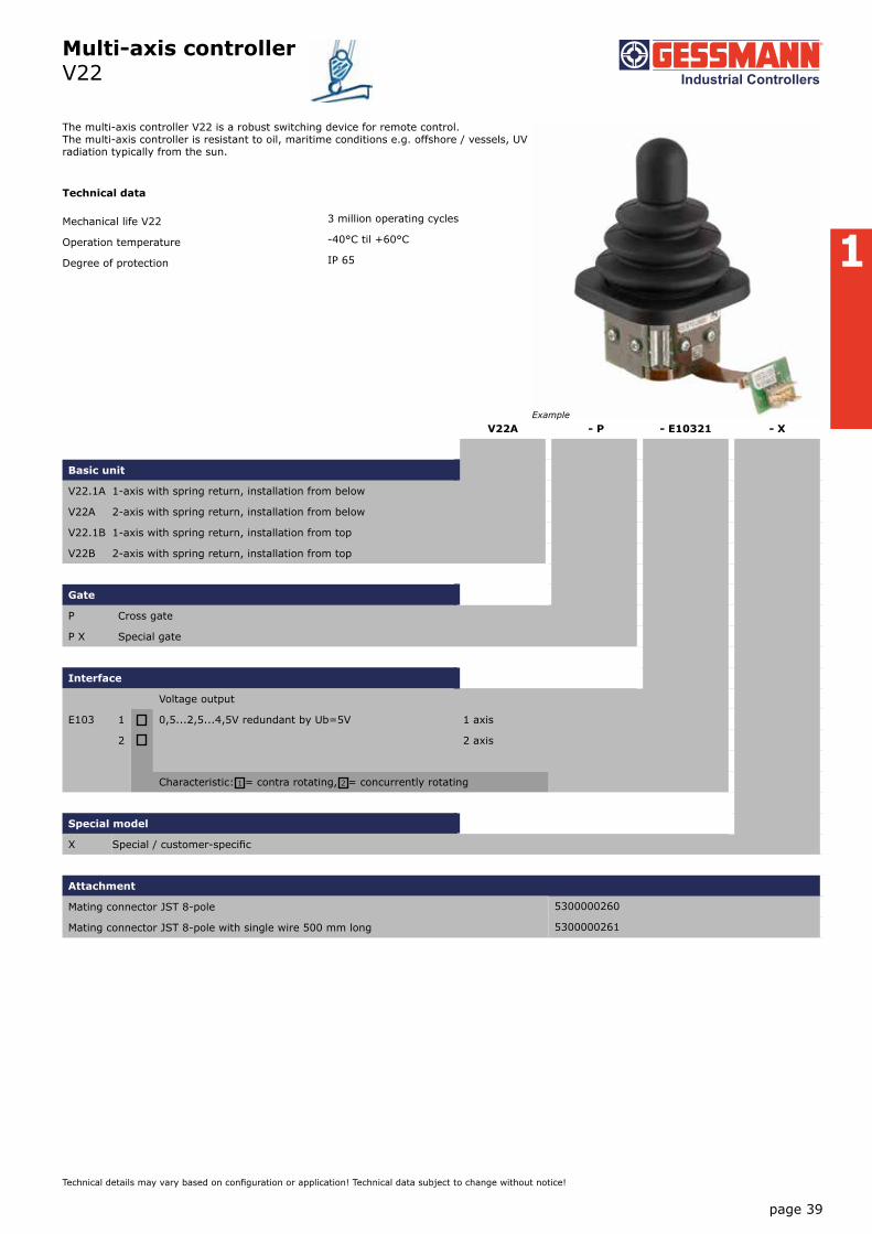
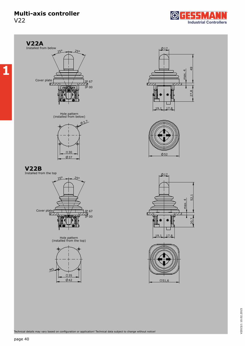
Multi-axis controller V22
The multi-axis controller V22 is a robust switching device for remote control. The multi-axis controller is resistant to oil, maritime conditions e.g. offshore / vessels, UV radiation typically from the sun.
Technical data
Mechanical life V22 3 million operating cycles
Operation temperature -40°C til +60°C
Degree of protection IP 65
V22A - P - E10321 - X
Basic unit
V22.1A 1-axis with spring return, installation from below
V22A 2-axis with spring return, installation from below
V22.1B 1-axis with spring return, installation from top
V22B 2-axis with spring return, installation from top
Gate
P Cross gate
P X Special gate
Interface
Voltage output
E103 1 0,5...2,5...4,5V redundant by Ub=5V 1 axis
2 2 axis
Characteristic: 1 = contra rotating, 2 = concurrently rotating
Special model
X Special / customer-specific
Attachment
Mating connector JST 8-pole 5300000260
Mating connector JST 8-pole with single wire 500 mm long 5300000261
Example
1
page 40
V20
15/1
10.
02.2
015
Technical details may vary based on configuration or application! Technical data subject to change without notice!
Multi-axis controller V22
25° 25°
V22AInstalled from below
IP 67
IP 00
17
max
. 4
17,8 19,1
49
27,
8
25° 25°
V22BInstalled from the top
Cover plate IP 67
IP 00
17
52,
1 2
0,7
max
. 4
17,8 19,1
52
51,6
37
30
2,7
Hole pattern(installed from below)
42 35
M3
Hole pattern(installed from the top)
1 / V22
Cover plate

1
page 41
Technical details may vary based on configuration or application! Technical data subject to change without notice!
Multi-axis controller V23
The multi-axis controller V23 is a robust switching device for remote control applications. The multi-axis controller is resistant to oil, maritime conditions e.g. offshore / vessels, UV radiation typically from the sun.
Technicalt data
Mechanical life V23 3 million operating cycles
Operation temperature -40°C til + 60°C
Degree of protection IP 67 front
V23A - P - C80 + C80 - X
Basic unit
V23.1A 1-axis with spring return, installation from below
V23A 2-axis with spring return, installation from below
V23.1B 1-axis with spring return, installation from top
V23B 2-axis with spring return, installation from top
Gate
P Cross gate
P X Special gate
Axis 1: direction 1-2
C80 Mechanical encoder
MEC 3-1
EA/26-10 l max. 1 mA
Potentiometer resistance 2x5 kOhm
Contact arrangement Arrangement MS 24
with 12-pol. JST-connector
Axis 2: direction 3-4 (not applicable to V23.1)
See describtion axis 1!
Special model
X Special / customer-specific
Attachment
Mating connector JST 12-polig (included in delivery!) 5300000263
Mating connector JST 12-pole with single wire 500 mm long 5300000264
Example

1
page 42
V20
15/1
10.
02.2
015
Technical details may vary based on configuration or application! Technical data subject to change without notice!
Multi-axis controller V23
25° 25° V23AInstalled from below
Cover plate IP 67
IP 00
17
max
. 4
17,8
48,
1 2
7,8
22,9
25° 25°
V23BInstalled from the top
Cover plate IP 67
IP 00
51,
1 2
4
max
. 4
17
18 22,9
52
55
37
30
2,7
Hole pattern(installed from below)
50
40 M3
Hole pattern(installed from the top)
1 / V23

1
Multi-axis controller V21
page 43
Technical details may vary based on configuration or application! Technical data subject to change without notice!
The multi-axis controller V21 is a robust hallsensor switching device for electro-hydraulic applications. The V21 is especially suitable for installation in our ball handles. The multi-axis controller is resistant to oil, maritime conditions e.g. offshore / vessels, UV radiation typically from the sun.
Technical data
Mechanical life 5 million operating cycles
Operating force 1,6 til 3,5N
Supply voltage 5VDC stabilized
Operation temperature -40°C til +60°C
Degree of protection IP 67
V21 P - 1 - E1032 - X
Basic unit
V21.1 1-axis, installation from top with fixing nut
V21 2-axis, installation from top with fixing nut
V21.1A 1-axis, with flange, installation from below
V21A 2-axis, with flange, installation from below
V21.1B 1-axis, with flange, installation from top
V21B 2-axis, with flange, installation from top
Gate
P Cross gate
P X Special gate
Knob
Standard
1 KBAD 980
Interface
Voltage output
E103 1 0,5...2,5...4,5V redundant by Ub=5V 1 axis
2 2 axis
Characteristic: 1 = concurrently rotating, 2 = contra rotating
Special model
X Special / customer-specific
Example

1
Multi-axis controller V21
page 44
V20
15/1
10.
02.2
015
Technical details may vary based on configuration or application! Technical data subject to change without notice!
max
.5
34
12
25° 25°
Cable outlet
Standardinstalled from the top
Cover plate
SW
30
26,5
Hole pattern
M24x1,5
max
.3
34
20
25° 25°
Cover housing
Version A with flangeinstalled from below
31
26,5
25 ±
0,1
2,7
Hole pattern
M24x1,5
max
.5 1
3
25° 25°
36
Version B with flangeinstalled from the top
with actuator KBAD 980
31
24,5
25 ±
0,1
2,7
Hole pattern
1 / 147
1
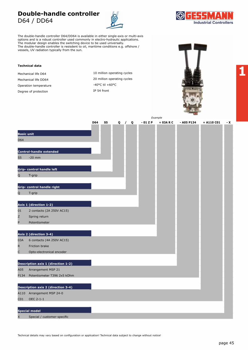
Double-handle controller D64 / DD64
page 45
Technical details may vary based on configuration or application! Technical data subject to change without notice!
The double-handle controller D64/DD64 is available in either single-axis or multi-axis options and is a robust controller used commonly in electro-hydraulic applications. The modular design enables the switching device to be used universally. The double-handle controller is resisdent to oil, maritime conditions e.g. offshore / vessels, UV radiation typically from the sun.
Technical data
Mechanical life D64 10 million operating cycles
Mechanical life DD64 20 million operating cycles
Operation temperature -40°C til +60°C
Degree of protection IP 54 front
D64 S5 Q / Q - 01 Z P + 03A R C - A05 P134 + A110 C01 - X
Basic unit
D64
Control-handle extended
S5 -20 mm
Grip- control handle left
Q T-grip
Grip- control handle right
Q T-grip
Axis 1 (direction 1-2)
01 2 contacts (2A 250V AC15)
Z Spring return
P Potentiometer
Axis 2 (direction 3-4)
03A 6 contacts (4A 250V AC15)
R Friction brake
C Opto-electronical encoder
Description axis 1 (direction 1-2)
A05 Arrangement MSP 21
P134 Potentiometer T396 2x5 kOhm
Description axis 2 (direction 3-4)
A110 Arrangement MSP 24-0
C01 OEC 2-1-1
Special model
X Special / customer-specific
Example

1
Double-handle controller D64 / DD64
Combination possibilities with our ball handles
page 46
V20
15/1
10.
02.2
015
Technical details may vary based on configuration or application! Technical data subject to change without notice!
D64 S5 Q / Q - 01 Z P + 03 A R C - A05 P134 + A110 C01 - X
Basic unit
D64 Identification of the installation variants with
reinforced version switching directions:
DD64
Control-handle long*
Standard 180 mm
S5 -20 mm
S8 +20 mm
*Only in combination with knob!
Grip- control handle left
Knob
M Mechanical zero interlock
T Dead man
H Signal button
D Push button
DV Flush push button
Q T-grip
QM T-grip with mechanical zero interlock
QMH T-grip with mechanical zero interlock + signal contact
QH T-grip + signal button
QD T-grip + push button side
B10 Palm grip B10... (see page 143)
Grip- control handle right
Knob
M Mechanical zero interlock
T Dead man
H Signal button
D Push button
DV Flush push button
Q T-grip
QM T-grip with mechanical zero interlock
QMH T-grip with mechanical zero interlock + signal contact
QH T-grip with signal button
QD T-grip push button side
B10... Palm grip B10... (see page 143)
1
2
3
43-4
D64 / DD64
B10
S. 143
1
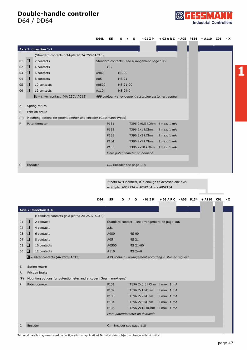
Double-handle controllerD64 / DD64
page 47
Technical details may vary based on configuration or application! Technical data subject to change without notice!
Axis 2: direction 3-4
(Standard contacts gold plated 2A 250V AC15)
01 2 contacts Standard contact - see arrangement on page 106
02 4 contacts z.B.
03 6 contacts A980 MS 00
04 8 contacts A05 MS 21
05 10 contacts A0500 MS 21-00
06 12 contacts A110 MS 24-0
A = silver contacts (4A 250V AC15) A99 contact - arrangement according customer request
Z Spring return
R Friction brake
(P) Mounting options for potentiometer and encoder (Gessmann-types)
P Potentiometer P131 T396 2x0,5 kOhm l max. 1 mA
P132 T396 2x1 kOhm l max. 1 mA
P133 T396 2x2 kOhm l max. 1 mA
P134 T396 2x5 kOhm l max. 1 mA
P135 T396 2x10 kOhm l max. 1 mA
More potentiometer on demand!
C Encoder C... Encoder see page 118
D64L S5 Q / Q - 01 Z P + 03 A R C - A05 P134 + A110 C01 - X
Axis 1: direction 1-2
(Standard contacts gold-plated 2A 250V AC15)
01 2 contacts Standard contacts - see arrangement page 106
02 4 contacts z.B.
03 6 contacts A980 MS 00
04 8 contacts A05 MS 21
05 10 contacts A0500 MS 21-00
06 12 contacts A110 MS 24-0
A = silver contact (4A 250V AC15) A99 contact - arrangement according customer request
Z Spring return
R Friction brake
(P) Mounting options for potentiometer and encoder (Gessmann-types)
P Potentiometer P131 T396 2x0,5 kOhm l max. 1 mA
P132 T396 2x1 kOhm l max. 1 mA
P133 T396 2x2 kOhm l max. 1 mA
P134 T396 2x5 kOhm l max. 1 mA
P135 T396 2x10 kOhm l max. 1 mA
More potentiometer on demand!
C Encoder C... Encoder see page 118
If both axis identical, it`s enough to describe one axis!
example: A05P134 + A05P134 => A05P134
D64 S5 Q / Q - 01 Z P + 03 A R C - A05 P134 + A110 C01 - X

1
Double-handle controllerD64 / DD64
D64 S5 Q / Q - 01 Z P + 03 A R C - A05 P134 + A110 C01 - X
Special model
X Special / customer-specific
Attachment
Indicating labels
Indicating labels engraved
page 48
V20
15/1
10.
02.2
015
Technical details may vary based on configuration or application! Technical data subject to change without notice!

1
Double-handle controller D64 / DD64
page 49
Technical details may vary based on configuration or application! Technical data subject to change without notice!
T = Dead man's buttonH = Signal buttonM = Latch for mechanical zero interlock
42
Knob solidD= Push button
To build in:Direction 1-2Direction 3-4
max
. 4
A
30
80 92
180
77
T MN
H M MP
Cover plate
CAGE CLAMP® connectionmax. 2,5mm²
IP 54
IP 00
PotentiometerT 130
96
B
30
80
80
5,580
80
Hole pattern
OEC-mounting
40°
4
0°
40°
4
0°
56
28
122
180
T - gripD = Push button
1 / 161
Type No. of contacts Dim. A Dim. B
01 2 119 82
02 4 131 94
03 6 144 107
04 8 156 119
05 10 169 132
06 12 181 144

1
Double-handle controller D8
page 50
V20
15/1
10.
02.2
015
Technical details may vary based on configuration or application! Technical data subject to change without notice!
The double-handle controller D8 is a robust switching device for the hoisting applications. The modular design enables the switching device to be used universally. The double-handle controller is resistant to oil, maritime conditions e.g. offshore /vessels, UV radiation typically from the sun.
Technical data
Mechanical life D8 10 million operating cycles
Operation temperature -40°C til +60°C
Degree of protection IP 54 front
D8 S5 Q / Q - 2ZP + 3 RP - B - A05 P184 + A050 P184 - E9012 - X
Basic unit
D8
Control-handle extended
S5 -20 mm
Grip- control-handle left
Q T-grip
Grip- control-handle right
Q T-grip
Axis 1 (direction 1-2)
2 2 contacts (1,5A 24VDC13)
Z Spring return
P Potentiometer
Axis 2 (direction 3-4)
3 3 contacts (1,5A 24VFC13)
R Friction brake
P Potentiometer
Cover housing
B Cover housing
Description axis 1 (direction 1-2)
A05 Arrangement MSP 21
P184 Potentiometer T301 2x5 kOhm
Description axis 2 (direction 3-4)
A050 Arrangement MSP 21-0
P184 Potentiometer T301 2x5 kOhm
Interface
E9012 Potentiometer output for proportional valve PVG32
Special model
X Special / customer-specific
Example

1
Double-handle controllerD8
Seite 51
Technische Angaben können je nach Konfiguration oder Einsatzfall abweichen! Technische Änderungen vorbehalten!
D8 S5 Q / Q - 2 Z P + 3 R P - B - A05 P184 + A050 P184 - E9012 - X
Basic unit
D8
Control-handle extended*
Standard 160 mm
S5 -20 mm
S8 +20 mm
*Only in combination with knob!
Grip- control-handle left
Knob
M Mechanical zero interlock
T Dead man
H Signal button
D Push button
Q T-grip
QD T-grip with push button side
B10... Palm grip B10... (see page 143)
Grip- control-handle right
Knob
M Mechanical zero interlock
T Dead man
H Signal button
D Push button
Q T-grip
QD T-grip with push button side
B10... Ball handle B10... (see page 143)
D8 S5 Q / Q - 2 Z P + 3 R P - B A05 P184 + A050 P184 - E9012 - X
Axis 1: direction 1-2 left
1 1 contact Standard contact - arrangement see page 106
2 2 contacts z.B.
3 3 contacts A98
A05
A050
A99 contact - arrangement for customer request
Z Spring return
R Friction brake
(P) Mounting options for potentiometer and encoder (Gessmann-types)
P Potentiometer P181 T301 2x0,5 kOhm l max. 1 mA
P182 T301 2x1 kOhm l max. 1 mA
P183 T301 2x2 kOhm l max. 1 mA
P184 T301 2x5 kOhm l max. 1 mA
P185 T301 2x10 kOhm l max. 1 mA
More potentiometer on demand!
Hall-potentiometer P43 T1360 0,5...2,5...4,5V / 4,5...2,5...0,5V
1
2
3
4
D8

1
Double-handle controller D8
Combination possibilities with our ball handles
page 52
V20
15/1
10.
02.2
015
Technical details may vary based on configuration or application! Technical data subject to change without notice!
If both axis identical, it`s enough to descrip one axis!
example:...A05P184 + A05P184 => A05P184
D8 S5 Q / Q - 2 Z P + 3 R P - B A05 P184 + A050 P184 - E9012 - X
Axis 2: direction 3-4
1 1 contacts Standard contact - arrangement see page 106
2 2 contacts z.B.
3 3 contacts A98
A05
A050
A99 contact - arrangement for customer request
Z Spring return
R Friction brake
(P) Mounting options for potentiometer and encoder (Gessmann-types)
P Potentiometer P181 T301 2x0,5 kOhm l max. 1 mA
P182 T301 2x1 kOhm l max. 1 mA
P183 T301 2x2 kOhm l max. 1 mA
P184 T301 2x5 kOhm l max. 1 mA
P185 T301 2x10 kOhm l max. 1 mA
More potentiometer on demand!
Hall-Potentiometer P43 T1360 0,5...2,5...4,5V / 4,5...2,5...0,5V
D8 S5 Q / Q - 2 Z P + 3 R P - B A05 P184 + A050 P184 - E9012 - X
Cover housing
B Cover housing
Interface
E901 1 Potentiometer output for proportional valve PVG32 0,25...0,5...0,75Us 1 axis
2 2 axis
Special model
X Special / customer-specific
B10
S. 143
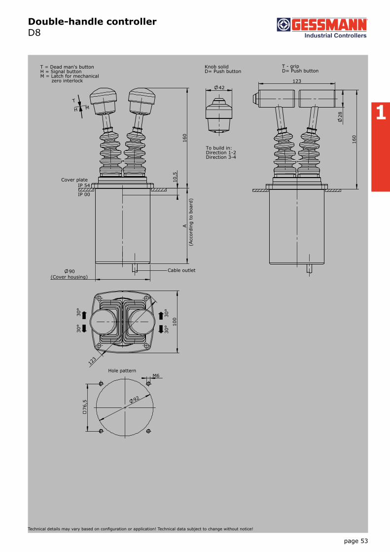
1
Double-handle controller D8
page 53
Technical details may vary based on configuration or application! Technical data subject to change without notice!
T = Dead man's buttonH = Signal buttonM = Latch for mechanical zero interlock
42
Knob solidD= Push button
To build in:Direction 1-2Direction 3-4
90(Cover housing)
10,
5
160
A
T
H M
Cable outlet
28
123
160
123
100
92
M6
76,5
Hole pattern
30°
30
°
30°
30
°
1 / 163
(Acc
ordi
ng t
o bo
ard)
IP 54
IP 00
Cover plate
T - gripD= Push button

1
Double-handle controller D85
page 54
V20
15/1
10.
02.2
015
Technical details may vary based on configuration or application! Technical data subject to change without notice!
The double-handle controller D85 is a robust switching device for hoisting applications. The modular design enables the switching device to be used universally. The double-handle controller is resistant to oil, maritime conditions e.g. offshore /vessels, UV radiation typically from the sun.
Technical data
Mechanical life D85 8 million operating cycles
Operation temperature -40°C til +60°C
Degree of protection IP 54 front
D85 S5 Q / Q - Z + R - B - E... - X
Basic unit
D85
Control-handle extended
Standard 160 mm
S5 -20 mm
S8 +20 mm
*Only available in combination with handle!
Grip- control-handle left
Knob
M Mechanical zero interlock
T Dead man
H Signal button
D Push button
Q T-grip
QD T-grip with push button side
B10... Palm grip B10... (see page 143)
Grip- control-handle right
see grip-control-handle left
Axis 1: direction 1-2 left
Z Spring return
R Friction brake
Axis 2: direction 3-4 left
Z Spring return
R Friction brake
Cover housing
B Cover housing
Interface (description see following pages)
E1xx Voltage output
E2xx Current output
E3xx CAN-interface
E4xx CANOpen Safety interface
Special model
X Special/ customer-specific
Example

1
Double-handle controller D85
Voltage outputs (not stabilized)
Supply voltage 4,75-5,25VDC
Mounting depth A 105 mm
Wiring Cable 500 mm long with plug (pins) CPC 17 - 14-pole
0,5...2,5...4,5V with 2 direction contacts per axis
1 axis E102 1
2 axis 2
Voltage output
Supply voltage 9-32VDC (*11,5-32)
Mounting depth A 105 mm
Wiring Cable 500 mm long with plug (pins) CPC 17 - 14-pole
2. cable (for grip function) 500 mm long with plug (socket) CPC 17 - 14-pole
0,5...2,5...4,5V + 2 direction contacts per axis
1 axis E110 1
2 axis 2
0...5...10V + 2 direction contacts per axis
1 axis E130 1
2 axis 2
10...0...10V + 2 direction contacts per axis
1 axis E144 1
2 axis 2
Voltage output with other value on request!
Current outputs
Supply voltage 9-32VDC
Mounting depth A 105 mm
Wiring Cable 500 mm long with plug (pins) CPC 17 - 14-pole
2. cable (for grip function) 500 mm long with plug (socket) CPC 17 - 14-pole
0...10...20 mA + 2 direction contacts per axis
1 axis E202 1
2 axis 2
20...0...20 mA + 2 direction contacts per axis
1 axis E220 1
2 axis 2
4...12...20 mA + 2 direction contacts per axis
1 axis E210 1
2 axis 2
20...4...20 mA + 2 direction contacts per axis
1 axis E221 1
2 axis 2
Voltage output with other value on request!
page 55
Technical details may vary based on configuration or application! Technical data subject to change without notice!

1
Double-handle controller D85
CAN
Supply voltage 9-36VDC
Idle current consumption 120 mA
Mounting depth A 105 mm (Expansion stage 1)
105 mm (Expansion stage 2)
120 mm (Expansion stage 3)
Protocol CANOpen CiA DS 301 or SAE J 1939
Baudrate 125 kBit/s til 1 Mbit/s
Output value 0...128...255
Wiring CAN (IN) cable 500 mm with plug M12 (pins)
CAN (OUT) cable 500 mm with plug M12 (socket)
External in-/outputs cable 500 mm with plug connector CPC 23-37 (socket)
CAN expansion stage 1 E304 1
- 3 analog joystick axis
- 14 digitale joystick functions
or 10 digital joystick functions + 4 LED-outputs
CAN expansion stage 2 E305 1
- 5 analog joystick axis
- 14 digital joystick functions
- Input for capacitive sensor
*external LED-outputs can be used in the grip for LED`s!
with additional external in-/output
- 4 external LED-outputs, 8 external digital inputs 2
CAN expansion stage 3 E306 1
- 8 analog joystick axis
- 14 digital joystick functions
- Input for capacitive sensor
*external LED-outputs can be used in the grip for LED`s!
with additional external in-/outputs
- 8 external LED-outputs, 8 external digital inputs 2
- 8 external LED-outputs, 16 external digital inputs 3
- 24 external digital inputs 4
- 8 external LED-outputs, 24 external digital inputs 5
with additional contact equipment separately wired (not CAN)
- 2 direction contacts + 1 zero position contact (not potential-free) per axis 1
- 1 zero position contact (potential-free) per axis 2
Profibus DP
Supply voltage 18-30VDC
Baudrate til 12MBit/s
Output value 0...128...255
Mounting depth A 105 mm
Wiring Profibus, cable 100 mm with plug D-Sub 9
Power supply (contact wiring) cable 500 mm with plug connector CPC 13-9 (pins)
External in-/outputs, cable 500 mm with plug connector CPC 23-37 (socket)
page 56
V20
15/1
10.
02.2
015
Technical details may vary based on configuration or application! Technical data subject to change without notice!
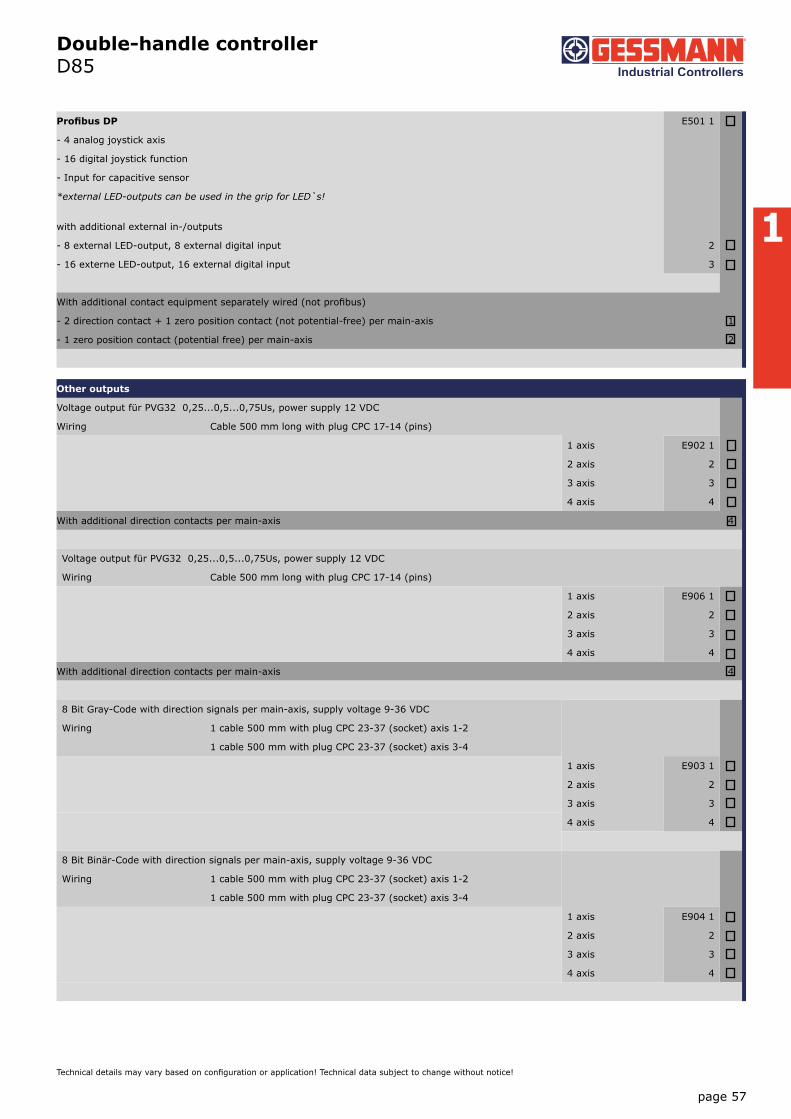
1
Double-handle controller D85
Profibus DP E501 1
- 4 analog joystick axis
- 16 digital joystick function
- Input for capacitive sensor
*external LED-outputs can be used in the grip for LED`s!
with additional external in-/outputs
- 8 external LED-output, 8 external digital input 2
- 16 externe LED-output, 16 external digital input 3
With additional contact equipment separately wired (not profibus)
- 2 direction contact + 1 zero position contact (not potential-free) per main-axis 1
- 1 zero position contact (potential free) per main-axis 2
Other outputs
Voltage output für PVG32 0,25...0,5...0,75Us, power supply 12 VDC
Wiring Cable 500 mm long with plug CPC 17-14 (pins)
1 axis E902 1
2 axis 2
3 axis 3
4 axis 4
With additional direction contacts per main-axis 4
Voltage output für PVG32 0,25...0,5...0,75Us, power supply 12 VDC
Wiring Cable 500 mm long with plug CPC 17-14 (pins)
1 axis E906 1
2 axis 2
3 axis 3
4 axis 4
With additional direction contacts per main-axis 4
8 Bit Gray-Code with direction signals per main-axis, supply voltage 9-36 VDC
Wiring 1 cable 500 mm with plug CPC 23-37 (socket) axis 1-2
1 cable 500 mm with plug CPC 23-37 (socket) axis 3-4
1 axis E903 1
2 axis 2
3 axis 3
4 axis 4
8 Bit Binär-Code with direction signals per main-axis, supply voltage 9-36 VDC
Wiring 1 cable 500 mm with plug CPC 23-37 (socket) axis 1-2
1 cable 500 mm with plug CPC 23-37 (socket) axis 3-4
1 axis E904 1
2 axis 2
3 axis 3
4 axis 4
page 57
Technical details may vary based on configuration or application! Technical data subject to change without notice!

1
Double-handle controller D85
Special model
Mating connector AMP CPC 17 14-pole (male insert) 5300000209
Mating connector AMP CPC 17 14-pole (male insert) with 2 m cable 5300000210
Mating connector AMP CPC 17 14-pole (socket contact) 5300000211
Mating connector AMP CPC 17 14-pole (socket contact) with 2 m cable 5300000213
Mating connector AMP CPC 23 37-pole (male insert) 5300000214
Mating connector AMP CPC 23 37-pole (male insert) with 2 m cable 5300000215
Mating connector AMP CPC 23 37-pole (socket contact) 5300000216
Mating connector AMP CPC 23 37-pole (socket contact) with 2 m cable 5300000217
Mating connector (CAN) M12 (male insert) with 2 m cable 20201140
Mating connector (CAN) M12 (socket contact) with 2 m cable 20202298
Mating connector (Profibus) straight 22201440
Mating connector (Profibus) 90° angled 22201741
page 58
V20
15/1
10.
02.2
015
Technical details may vary based on configuration or application! Technical data subject to change without notice!

1
Double-handle controller D85
page 59
Technical details may vary based on configuration or application! Technical data subject to change without notice!
T = Dead man's buttonH = Signal button
42
Knob solidD= Push button
To build in:Direction 1-2Direction 3-4
90(Cover housing)
10,
5
160
A
T
H
Cable outlet
28
123
160
123
100
92
M6
76,5
Hole pattern
30°
30
°
30°
30
°
1 / D85
(Acc
ordi
ng
to b
oard
)
IP 54
IP 00
Cover plate
T - gripD= Push button

1
Double-handle controller D3
page 60
V20
15/1
10.
02.2
015
Technical details may vary based on configuration or application! Technical data subject to change without notice!
The double-handle controller D3 is a robust switching device for nautical navigation applications. The modular design enables the switching device to be used universally. The double-handle controller is resistant to oil, maritime conditions e.g. offshore /vessels, UV radiation typically from the sun.
Technical data
Mechanical life D3 12 million operating cycles
Operation temperature -40°C til +60°C
Degree of protection IP 66 front
D3 S5 Q / Q - 2 R P + 3 R P - B - A05 P214 - A050 P214 - E1292 - X
Basic unit
D3
Control-handle extended
S5 -20 mm
Grip- control handle left
Q T-grip
Grip- control handle right
Q T-grip
Axis 1 (direction 1-2)
2 2 contacts (1,5A 24VDC13)
R Friction brake
P Potentiometer
Axis 2 (direction 3-4)
3 3 contacts (1,5A 24VDC13)
R Friction brake
P Potentiometer
Cover housing
B Cover housing
Description axis 1 (direction 1-2)
A05 Arrangement MSP 21
P214 Potentiometer T246 2x5kOhm
Description axis 2 (direction 3-4)
A050 Arrangement MSP 21-0
P214 Potentiometer T246 2x5kOhm
Interface
E1292 Voltage output 0...5...10V
Special model
X Special / customer-specific
Example

1
Double-handle controller D3
Combination possibilities with our ball handles
page 61
Technical details may vary based on configuration or application! Technical data subject to change without notice!
D3 S5 Q / Q - 2 R P + 3 R P - B - A05 P214 + A050 P214 - E1292 - X
Basic unit
D3 Identification of the installation variants with switching directions:
Control-handle extended*
Standard 148 mm
S5 -20 mm
S8 +20 mm
*Only available in combination with handle!
Grip - control-handle left
Knob
D Push button
Q T-grip
QD T-grip with push button side
Grip - control-handle right
Knob
D Push button
Q T-grip
QD T-grip with push button side
D3 S5 Q / Q - 2 R P + 3 R P - B - A05 P214 + A050 P214 - E1292 - X
Axis 1: direction 1-2 left
1 1 contact Standard contact- arrangement see page 106
2 2 contacts z.B.
3 3 contacts A98 MS 0
A05 MS 21
A050 MS 21-0
A99 contact - arrangement according customer request
R Friciton brake
(P) Mounting options for potentiometer and (Gessmann-types)
P Potentiometer P211 T246 2x0,5 kOhm l max. 1 mA
P212 T246 2x1 kOhm l max. 1 mA
P214 T246 2x5 kOhm l max. 1 mA
P215 T246 2x10 kOhm l max. 1 mA
More potentiometer on demand!
Hall-Potentiometer P42 T1003 0,5...2,5...4,5V / 4,5...2,5...0,5V
1 3
2 4
D3
B10
S. 143

1
Double-handle controller D3
page 62
V20
15/1
10.
02.2
015
Technical details may vary based on configuration or application! Technical data subject to change without notice!
If both axis identical, it`s enough to describ one axis!
example: ...A05P214 + A05P214 => A05P214
D3 S5 Q / Q - 2 R P + 3 R P - B - A05 P214 + A050 P214 - E1292 - X
Axis 2: direction 3-4 left
1 1 contact Standard contact- arrangement see page 106
2 2 contacts z.B.
3 3 contacts A98 MS 0
A05 MS 21
A050 MS 21-0
A99 contact - arrangement according customer request
R Friction brake
(P) Mounting options for potentiometer (Gessmann-types)
P Potentiometer P211 T246 2x0,5 kOhm l max. 1 mA
P212 T246 2x1 kOhm l max. 1 mA
P214 T246 2x5 kOhm l max. 1 mA
P215 T246 2x10 kOhm l max. 1mA
More potentiometer on demand!
Hall-Potentiometer P43 T1003 0,5...2,5...4,5V/4,5...2,5...0,5V
D3 S5 Q / Q - 2 R P + 3 R P - B - A05 P214 + A050 P214 - E1292 - X
Cover housing
B Cover housing
Interface (description the following pages)
Potentiometer output
E1xx Voltage output
E2xx Current output
Special model
X Special / customer-specific
Voltage outputs
Supply voltage 11,5-32VDC
Wiring Cable 500 mm long with plug (pins) CPC 17 - 14-pole
0...5...10V per axis
1 axis E129 1
2 axis 2
10...0...10V per axis
1 axis E141 1
2 axis 2
-10...0...+10V per axis
1 axis E140 1
2 axis 2
Voltage output with other value on request!

1
Double-handle controller D3
page 63
Technical details may vary based on configuration or application! Technical data subject to change without notice!
Current outputs
Supply voltage 18-36VDC
Wiring Cable 500 mm long with plug (pins) CPC 17 - 14-pole
4...12...20 mA per axis
1 axis E209 1
20...4...20 mA per axis
1 axis E217 1
Attachment
Mating connector AMP CPC 17 14-pole (socket contact) 5300000211
Mating connector AMP CPC 17 14-pole (socket contact) with 2 m cable 5300000213

1
Double-handle controller D3
page 64
V20
15/1
10.
02.2
015
Technical details may vary based on configuration or application! Technical data subject to change without notice!
120
80
67,
5 8
6
26
60° 60°
Cable importFilter plug
IP 66
IP 00
Cover plate
80 96,5
148
1
03
101
16
25
Adjusting screwfor friction brake
157
154
Knob solidD= Push button
6
100
84
82
Hole pattern
T- gripD=Push button
Direction 1-2 Direction 3-4
1 / 165
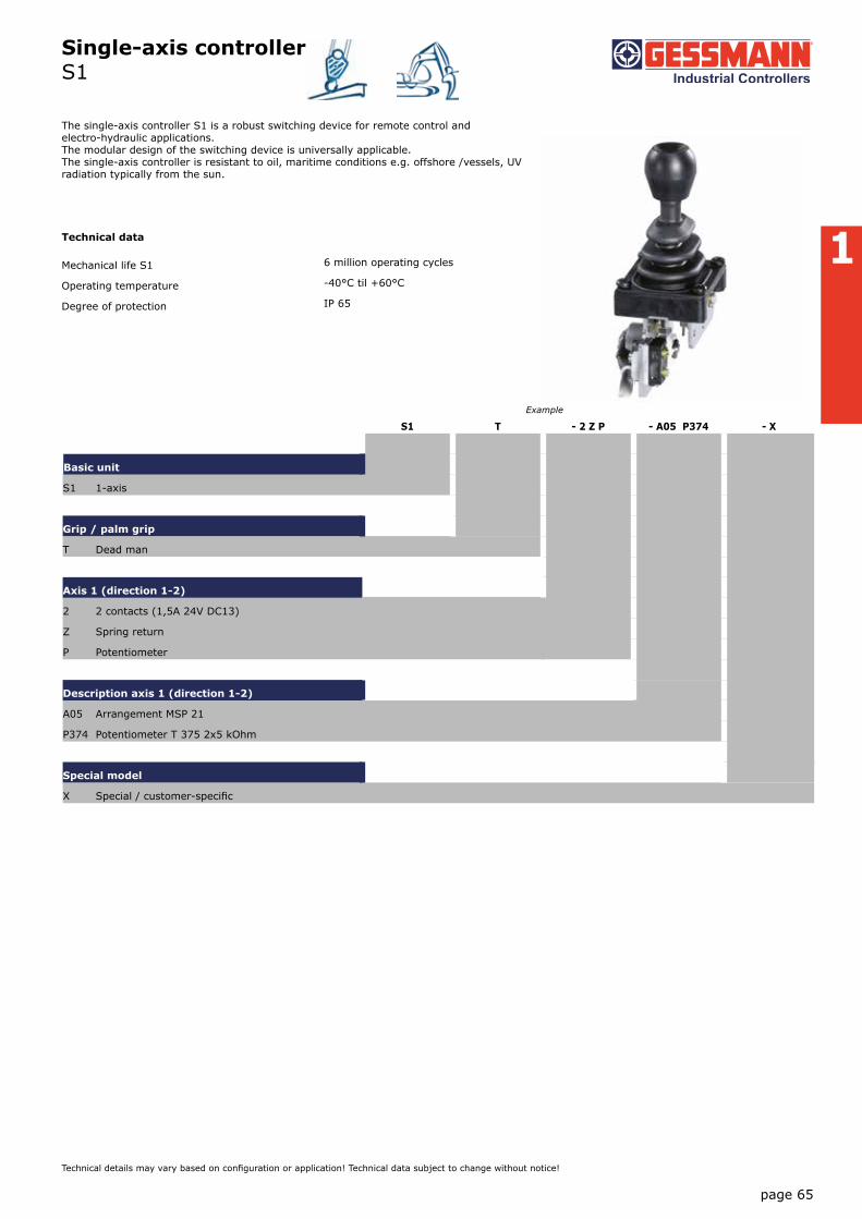
Single-axis controller S1
1
page 65
Technical details may vary based on configuration or application! Technical data subject to change without notice!
The single-axis controller S1 is a robust switching device for remote control and electro-hydraulic applications. The modular design of the switching device is universally applicable. The single-axis controller is resistant to oil, maritime conditions e.g. offshore /vessels, UV radiation typically from the sun.
Technical data
Mechanical life S1 6 million operating cycles
Operating temperature -40°C til +60°C
Degree of protection IP 65
S1 T - 2 Z P - A05 P374 - X
Basic unit
S1 1-axis
Grip / palm grip
T Dead man
Axis 1 (direction 1-2)
2 2 contacts (1,5A 24V DC13)
Z Spring return
P Potentiometer
Description axis 1 (direction 1-2)
A05 Arrangement MSP 21
P374 Potentiometer T 375 2x5 kOhm
Special model
X Special / customer-specific
Example

Single-axis controller S1
1
page 66
V20
15/1
10.
02.2
015
Technical details may vary based on configuration or application! Technical data subject to change without notice!
S1 T - 2 Z P - A05 P374 - X
Basic unit
S1 1-axis
Grip / palm grip
Knob (standard)
M Mechanical zero interlock
T Dead man
D Push button
GS8 Knob GS8
S1 T - 2 Z P - A05 P374 - X
Axis 1: direction 1-2 left
1 1 contact Standard contact - arrangement see page 106
2 2 contacts z.B.
3 3 contacts A05 MS 21
4 4 contacts A050 MS 21-0
A060 MS 22-0
A99 contact - arrangement according customer request
Z Spring return (included in basic unit!)
R Friction brake
P Potentiometer P372 T375 2x1 kOhm l max. 1 mA
P374 T375 2x5 kOhm l max. 1 mA
P274 T430 2x5 kOhm l max. 1 mA
with direction track
S1 T - 2 Z P - A05 P374 - X
Special model
X Special / customer-specific

Single-axis controller S1
1
24 2
57
25° 25°
Knob GS8
25
21 20
63,
50
63
max
. 2
18,5 18,5 R14,5
12
20
20
4,5
Hole pattern
Cover plate IP 65
PotentiometerT 375 / T 432
IP 00
Knob solid GK4
44
52
26
33
59
30
58
15
T = Dead man's button
1 / 181
page 67
Technical details may vary based on configuration or application! Technical data subject to change without notice!
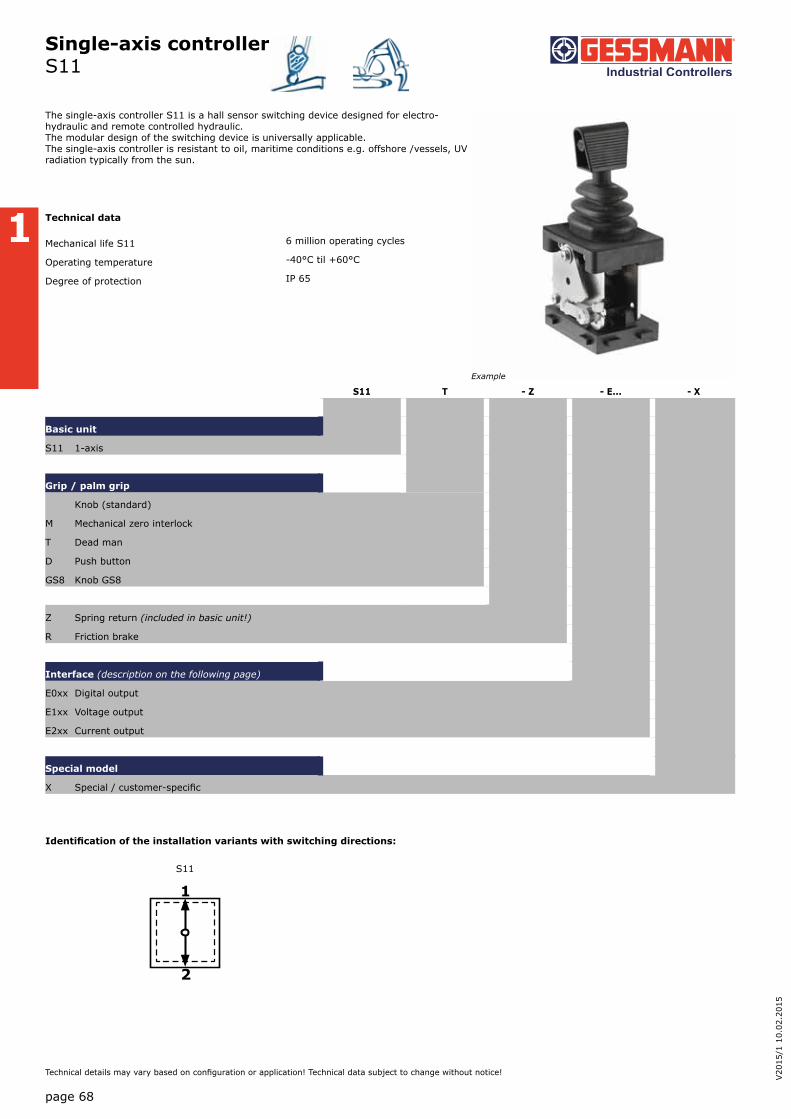
Single-axis controller S11
Identification of the installation variants with switching directions:
Example
1
2
S11
1
page 68
V20
15/1
10.
02.2
015
Technical details may vary based on configuration or application! Technical data subject to change without notice!
The single-axis controller S11 is a hall sensor switching device designed for electro- hydraulic and remote controlled hydraulic. The modular design of the switching device is universally applicable. The single-axis controller is resistant to oil, maritime conditions e.g. offshore /vessels, UV radiation typically from the sun.
Technical data
Mechanical life S11 6 million operating cycles
Operating temperature -40°C til +60°C
Degree of protection IP 65
S11 T - Z - E... - X
Basic unit
S11 1-axis
Grip / palm grip
Knob (standard)
M Mechanical zero interlock
T Dead man
D Push button
GS8 Knob GS8
Z Spring return (included in basic unit!)
R Friction brake
Interface (description on the following page)
E0xx Digital output
E1xx Voltage output
E2xx Current output
Special model
X Special / customer-specific

Single-axis controller S11
Digital Output
Supply voltage 9-32VDC
Current carrying capacity Direction signal 150 mA
Zero position signal 500 mA
Wiring Cable 500 mm long with plug (pins) Mini-Mate-N-Lok 10-pole
Cable 500 mm long with plug (pins)
1 axis E001 1
Voltage output (not stabilized)
Supply voltage 4,75-5,25VDC
Current carrying capacity Direction signal 8 mA
Wiring Cable 500 mm long with plug (pins) Mini-Mate-N-Lok 10-pole
Characteristic: 1 = contra rotating, 2 = concurrently rotating
0,5...2,5...4,5V redundant + 2 direction signal per axis
1 axis E104 1
Voltage output
Supply voltage 9-32VDC (*11,5-32V)
Current carrying capacity Direction signal 150 mA
Zero position signal 500 mA
Wiring Cable 500 mm long with plug (pins) Mini-Mate-N-Lok 10-pole
Characteristic: 1 = contra rotating, 2 = concurrently rotating
0,5...2,5...4,5V redundant + 2 direction signal + 1 zero position signal (galvanically isolated) per axis
1 axis E112 1
0...5...10V redundant + 2 direction signal + 1 zero position signal (galvanically isolated) per axis, supply voltage 11,5 - 32VDC
1 axis E132 1
10...0...10V redundant + 2 direction signal + 1 zero position signal (galvanically isolated) per axis, supply voltage 11,5 - 32VDC,
sensor redundant, 1 output with signal monitoring
1 axis E136 1
Voltage output with other value on request!
1
page 69
Technical details may vary based on configuration or application! Technical data subject to change without notice!

Single-axis controller S11
Attachment
Mating connector AMP Mini-Mate-N-LoK 10-pole (socket contact) 5300000963
Mating connector AMP Mini-Mate-N-LoK 10-pole (socket contact) with 2 m cable 5300000964
4...12...20mA redundant + 2 direction signal + 1 zero position signal (galvanically isolated) per axis, sensor redundant,
1 output with signal monitoring
1 axis E214 1
20...4...20mA redundant + 2 direction signal + 1 zero position signal (galvanically isolated) per axis, sensor redundant,
1 output with signal monitoring
1 axis E216 1
Voltage output with other value on request!
Current output
Supply voltage 9-32VDC
Current carrying capacity Direction signal 150 mA
Zero position signal 500 mA
75 mm (from 3 axis)
Wiring Cable 500 mm long with plug (pins) CPC 13 - 9-pole
0...10...20mA redundant + 2 direction signal + 1 zero position signal (galvanically isolated) per axis, sensor redundant,
1 output with signal monitoring with signal monitoring
1 axis E206 1
20...0...20mA redundant + 2 direction signal + 1 zero position signal (galvanically isolated) per axis, sensor redundant,
1 output with signal monitoring
1 axis E208 1
1
page 70
V20
15/1
10.
02.2
015
Technical details may vary based on configuration or application! Technical data subject to change without notice!
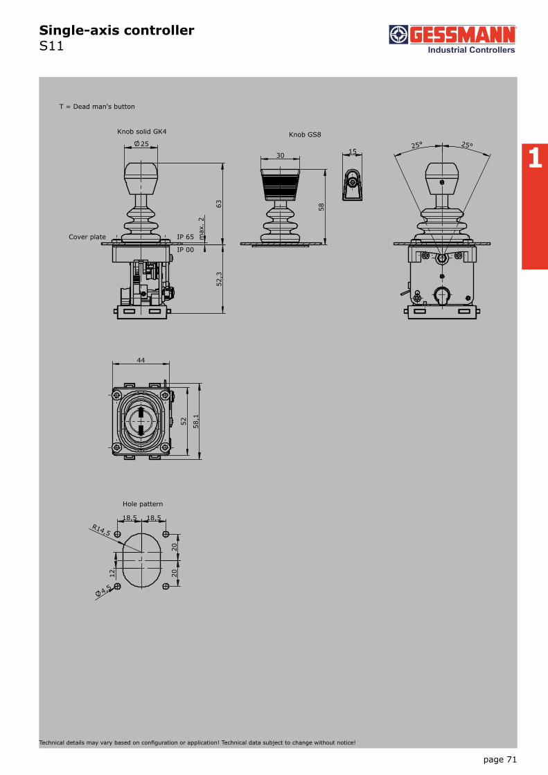
Single-axis controller S11
1 25° 25°
Knob GS8 25
63
max
. 2
52,
3
18,5 18,5 R14,5
12
20
20
4,5
Hole pattern
Cover plate IP 65
IP 00
Knob solid GK4
44
52
58,
1
30
58
15
T = Dead man's button
1 / S11
page 71
Technical details may vary based on configuration or application! Technical data subject to change without notice!

Single-axis controller S14
1
2
1
page 72
V20
15/1
10.
02.2
015
Technical details may vary based on configuration or application! Technical data subject to change without notice!
S14L S8 T - 01ZC + A05 C61 - X
Basic unit
S14L
Control-handle extended
S8 +20 mm
Grip / palm grip
T Dead man
Axis 1 (direction 1-2)
01 2 contacts (2A 250V AC15)
Z Spring return
C Mechanical encoder
Description axis 1 (direction 1-2)
A05 Arrangement MSP 21
C61 Mechanical encoder MEC 1-2
Special model
X Special / customer-specific
S14L S8 T - 01ZC + A05 C61 - X
Basic unit
S14L 1-axis left
S14R 1-axis right
Control-handle extended
Standard Identification of the installation
S8 +20 mm variants with switching directions:
Grip / palm grip
Knob (standard)
M Mechanical zero interlock
MH Mechanical zero interlock + signal contact
T Dead man
H Signal button
GK1 Knob 42 mm
GK1M Mechanical zero interlock
GK1MN Mechanical zero interlock (push down)
GK1T Dead man
GK1H Signal button
GK1MH Mechanical zero interlock + signal contact
S14
The single-axis controller S14 is a designed hall sensor switching device for electro-hydraulic and remote controlled hydraulic. The modular design of the switching device is universally applicable. The single-axis controller is resistant to oil, maritime conditions e.g. offshore /vessels, UV radiation typically from the sun.
Techical data
Mechanical life S14 6 million operating cycles
Operating temperature -40°C til +60°C
Degree of protection IP 65
Example

Single-axis controller S14
1
page 73
Technical details may vary based on configuration or application! Technical data subject to change without notice!
S14L S8 T - 01ZC + A05 C61 - X
GK1D Push button
GK1DV Flush push button
GSP Twist Handle 2x5 kOhm + direction track Imax= 1 mA
B ... Palm grip B... (see page palm grip 128)
Attention! The single-axis controller S14 is not suited for big palm grip (B3, B7/B8, B9...)!
S14L S8 T - 01ZC + A05 C61 - X
Axis 1: direction 1-2 left / direction 5-6 right
(Standard contacts gold-plated 2A 250V AC15)
01 2 contacts Standard contact - arrangement see page 106
02 4 contacts z.B.
03 6 contacts A05 MS 21
A0500 MS 21-00
A110 MS 24-0
A99 contact - arrangement according customer request
Z Spring return (included in basic unit!)
R Friction brake
C Mechanical encoder C61 MEC 1-2
EA/02-10 l max. 1 mA
Potentiometer track 2x10 kOhm
Direction track Arrangement MS 26-0
C62 MEC 1-7
EA/10-10 l max. 1 mA
Potentiometer track 2x5 kOhm
Direction track Arrangement MS 26-0-1
C66 MEC 1-10
EA/17-10 l max. 1 mA
Potentiometer track 2x1,5 kOhm
Direction track Arrangement MS 21-0+MS 21
C63 MEC 1-6
EA/09-10
6 Bit Gray Code
C64 MEC 1-6-5
ER/36-10 Us= 18-30V
Current output 20...4...20mA
C65 MEC 1-6-8
ER/ 36-10 Us= 18-30V
Current output 20...0...20mA
C67 MEC 1-6-9
ER/36-11 Us= 18-30V
Voltage output 10...0...10V
More potentiometer on request!
S14L S8 T - 01ZC + A05 C61 - X
Special model
X Special / customer-specific

Single-axis controller S14
1
5660
25
40
26
B 28
8
max
4
T
H M
IP 65
IP 00
Cover plate
Mechanical encoder
Board with solderor plug terminal
CAGE CLAMP® connectionmax. 1,5mm²
65
50
40° 40°
5452
38
20
3,516
40
Hole pattern
42
Knob solid GKfor MN, MP
27
Knob solid GSPfor 3.direction 11-12
T = Dead man's buttonH = Signal buttonM = Latch for mechanical zero interlock
1 / 189
Type No. ofcontacts Dim. B
01 2 24
02 4 33
03 6 42
page 74
V20
15/1
10.
02.2
015
Technical details may vary based on configuration or application! Technical data subject to change without notice!

Single-axis controller S2 / SS2 / S21
Example
1
page 75
Technical details may vary based on configuration or application! Technical data subject to change without notice!
The single-axis controller S2/SS2 is a robust switching device for remote controlled and electrohydraulic applications. The modular design of the switching device is universally applicable. The single-axis controller is resistant to oil, maritime conditions e.g. offshore /vessels, UV radiation typically from the sun.
Technical data
Mechanical life S2 / S21 6 million operating cycles
Mechanical life SS2 10 million operating cycles
Operating temperature -40°C til +60°C
Degree of protection IP 54
S2L S5 T - 02 Z P - A050 P134 - X
Basic unit
S2L left
Control-handle extended
S5 -20 mm
*Only possible in combination with handle!
Grip / palm grip
T Dead man
Axis 1 (direction 1-2)
02 3 contacts (2A 250V AC15)
Z Spring return
P Potentiometer
Description axis 1 (direction 1-2)
A050 Arrangement MSP 21
P134 Potentiometer T396 2x5 kOhm
Special model
X Special / customer-specific
S2L S5 T - 02 Z P - A050 P134 - X
Basic unit
S2L Single-axis controller left Identification of the installation variants
S2R Single-axis controller right with switching directions:
S21L Single-axis controller left with flange 96x96 mm
S21R Single-axis controller right with flange 96x96 mm
reinforced version
SS2L Single-axis controller left
SS2R Single-axis controller right
SS21L Single-axis controller left with flange 96x96 mm
SS21R Single-axis controller right with flange 96x96 mm
1
2
1-2
left
5
6
5-6
right

Single-axis controller S2 / SS2 / S21
Combination possibilities with our ball handles
1
page 76
V20
15/1
10.
02.2
015
Technical details may vary based on configuration or application! Technical data subject to change without notice!
S2L S5 T - 02 Z P - A050 P134 - X
Control-handle extended
Standard
S5 -20 mm
S8 +20 mm
Grip / palm grip
Knob (standard)
M Mechanical zero interlock
MN Mechanical zero interlock (push down)
T Dead man
MT Mechanical zero interlock + dead man
H Signal button
MH Mechanical zero interlock + signal button
D Push button
MD Mechanical zero interlock + push button
DV Flush push button
MDV Mechanical zero interlock + flush push button
B... Palm grip B... (see page palm grip 128)
S2L S5 T - 02 Z P - A050 P134 - X
Axis 1: direction 1-2 left / direction 5-6 right
02 3 contacts Standard contact - arrangement see page 106
03 5 contacts z.B.
04 7 contacts A98 MS 0
05 9 contacts A05 MS 21
A0500 MS 21-00
A110 MS 24-0
A99 contact - arrangement according customer request
Z Spring return
R Friction brake
(P) Possibility of mounting potentiometer and encoder (Gessmann-types)
P Potentiometer P131 T396 2x0,5 kOhm l max. 1 mA
P132 T396 2x1 kOhm l max. 1 mA
P133 T396 2x2 kOhm l max. 1 mA
P134 T396 2x5 kOhm l max. 1 mA
P135 T396 2x10 kOhm l max. 1 mA
More potentiometer on request!
C Encoder C... Encoder see page 118
B1 B5 B6 B10 B22 B24 B29
S. 128 S. 135 S. 137 S. 143 S. 149 S. 153 S. 157

Single-axis controller S2 / SS2 / S21
1
page 77
Technical details may vary based on configuration or application! Technical data subject to change without notice!
S2L S5 T - 02 Z P - A050 P134 - X
Special model
X Special / customer-specific
X1 Microswitch (MZT 1) positively driven NC contact
Attachment
Indicating labels
Indicating labels with engraving

Single-axis controller S2 / SS2 / S21
1
T = Dead man's buttonH = Signal buttonM = Latch for mechanical zero interlock
42
Knob solidD= Push button
24 21 18
88
max
. 4
120
T MN
H M
Cover plate
PotentiometerT130
IP 54
IP 00
42
37,5° 37,5°
90
80
45 B
20,5
3,20
36,5 ±0,2
Hole pattern
145
35
Palm grip B5B5 T = Dead man's button
1 / 201
Type No. ofcontacts Maß B
02 3 62
03 5 72
04 7 83
05 9 93
page 78
V20
15/1
10.
02.2
015
Technical details may vary based on configuration or application! Technical data subject to change without notice!
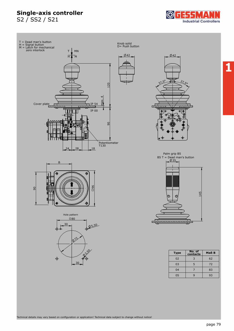
Single-axis controller S2 / SS2 / S21
1
T = Dead man's buttonH = Signal buttonM = Latch for mechanical zero interlock
42
Knob solidD= Push button
24 28 18
90
max
. 4
120
T MN
H M
Cover plate
PotentiometerT130
IP 54
IP 00
42
37,5° 37,5°
90
B
96
145
35
5,50
72
80
30
30
3,50
Hole pattern
Palm grip B5B5 T = Dead man's button
1 / 203
Type No. of contacts Maß B
02 3 62
03 5 72
04 7 83
05 9 93
page 79
Technical details may vary based on configuration or application! Technical data subject to change without notice!

Single-axis controller S22 / SS22
Example
1
page 80
V20
15/1
10.
02.2
015
Technical details may vary based on configuration or application! Technical data subject to change without notice!
The single-axis controller S2/SS2 is a robust switching device for remote controlled and electrohydraulic applications. The modular design of the switching device is universally applicable. The single-axis controller is resistant to oil, maritime conditions e.g. offshore /vessels, UV radiation typically from the sun.
Technical data
Mechanical life S22 6 million operating cycles
Mechanical life SS22 10 million operating cycles
Operating temperature -40°C til +60°C
Degree of protection IP 54
S22L S5 T - 3 Z P - A050 P134 - X
Basic unit
S22L left
Control-handle extended
S5 -20 mm
Grip / palm grip
T Dead man
Axis 1 (direction 1-2)
3 3 contacts (2A 250V AC15)
Z Spring return
P Potentiometer
Description axis 1 (direction 1-2)
A050 Arrangement MSP 21
P134 Potentiometer T396 2x5 kOhm
Special model
X Special / customer-specific
S22L S5 T - 3 Z P - A050 P134 - X
Basic unit
S22L Single-axis controller left Identification of the installation variants
S22R Single-axis controller right with switching directions:
reinforced version
SS22L Single-axis controller left
SS22R Single-axis controller right
Control-handle extended
Standard
S5 -20 mm
S8 +20 mm
1
2
1-2
S22L / SS22L
5
6
5-6
S22R / SS22R

Single-axis controller S22 / SS22
Combination possibilities with our ball handles
1
page 81
Technical details may vary based on configuration or application! Technical data subject to change without notice!
S22L S5 T - 3 Z P - A050 P134 - X
Grip / palm grip
Knob (standard)
M Mechanical zero interlock
MN Mechanical zero interlock (push down)
T Dead man
MT Mechanical zero interlock + dead man
H Signal button
MH Mechanical zero interlock + signal button
D Push button
MD Mechanical zero interlock + push button
DV Flush push button
MDV Mechanical zero interlock + flush push button
B... Palm grip B... (see page palm grip 128)
S22L S5 T - 3 Z P - A050 P134 - X
Axis 1: direction 1-2 left / direction 5-6 right
1 1 contact Standard contact - arrangement see page 106
2 2 contacts z.B.
3 3 contacts A98 MS 0
4 4 contacts A05 MS 21
A0500 MS 21-00
A99 contact - arrangement according customer request
Z Spring return
R Friction brake
(P) Possibility of mounting potentiometer and encoder (Gessmann-types)
P Potentiometer P131 T396 2x0,5 kOhm l max. 1 mA
P132 T396 2x1 kOhm l max. 1 mA
P133 T396 2x2 kOhm l max. 1 mA
P134 T396 2x5 kOhm l max. 1 mA
P135 T396 2x10 kOhm l max. 1 mA
More potentiometer on request!
C Codierer C...Encoder see page 118
B1 B5 B6 B10
S. 128 S. 135 S. 137 S. 143

Single-axis controller S22 / SS22
1
page 82
V20
15/1
10.
02.2
015
Technical details may vary based on configuration or application! Technical data subject to change without notice!
S22L S5 T - 3 Z P - A050 P134 - X
Special model
X Special / customer-specific
X1 Switching run 2-0-2
Attachment
Indicating labels
Indicating labels with engraving

Single-axis controller S22 / SS22
T = TotmanntasterH = SignaltasterM = mech. Nullstellungs- verriegelung
42
GriffkugelD= Drucktaster
88
max
. 4
120
16 18
T MN
H M
Einbauplatte
PotentiometerT130
IP 54
IP 00
42
37,5° 37,5°
80
45
B
90
20,5
3,20
36,5 ±0,2
Einbauöffnung
145
35
Ballengriff B5B5 T = Totmanntaster
1 / 205
Form Kontakt-zahl Maß B
1 1 25
2 2 31
3 3 36
4 4 42
1
T = Dead man's buttonH = Signal buttonM = Latch for mechanical zero interlock
42
Knob solidD= Push button
88
max
. 4
120
16 18
T MN
H M
Cover plate
PotentiometerT130
IP 54
IP 00
42
37,5° 37,5°
80
45
B
90
20,5
3,20
36,5 ±0,2
Hole pattern
145
35
Palm grip B5B5 T = Dead man's button
1 / 205
Type No. of contacts Dim. B
1 1 25
2 2 31
3 3 36
4 4 42
page 83
Technical details may vary based on configuration or application! Technical data subject to change without notice!

Single-axis controller S23
1
page 84
V20
15/1
10.
02.2
015
Technical details may vary based on configuration or application! Technical data subject to change without notice!
The single-axis controller S23 is a robust swithing device for shipbuilding and electro- hydraulic applications. The modular design of the switching device is universally applicable. The single-axis controller is resistant to oil, maritime conditions e.g. offshore /vessels, UV radiation typically from the sun.
Technical data
Mechanical life S23 6 million operating cycles
Operating temperature -40°C til +60°C
Degree of protection IP 65
S23L S5 M - 3 Z P - A050 P134 - X
Basic unit
S23L left
Control-handle extended
S5 -20 mm
Grip / palm grip
M Mechanical zero interlock
Axis 1 (direction 1-2)
3 3 contacts (2A 250V AC15)
Z Spring return
P Potentiometer
Description axis 1 (direction 1-2)
A050 Arrangement MSP 21-0
P134 Potentiometer T396 2x5 kOhm
Special model
X Special / customer-specific
S23L S5 M - 3 Z P - A050 P134 - X
Basic unit
S23L left Identification of the installation variants
S23R right with switching directions:
Control-handle extended
Standard 140 mm
S5 -20 mm
S8 +20 mm
1
2
1-2
S23
5
6
5-6
Example

Single-axis controller S23
1
page 85
Technical details may vary based on configuration or application! Technical data subject to change without notice!
S23L S5 M - 3 Z P - A050 P134 - X
Grip / palm grip
Knob (standard)
M Mechanical zero interlock
Q T-grip
QM T-grip with mechanical zero interlock
S23L S5 M - 3 Z P - A050 P134 - X
Axis 1: direction 1-2 left / direction 5-6 right
1 1 contact Standard contact - arrangement see page 106
2 2 contacts z.B.
3 3 contacts A98 MS 0
4 4 contacts A05 MS 21
A0500 MS 21-00
A99 contact - arrangement according customer request
Z Spring return
R Friction brake
(P) Possibility of mounting potentiometer and encoder (Gessmann-types)
P Potentiometer P131 T396 2x0,5 kOhm l max. 1 mA
P132 T396 2x1 kOhm l max. 1 mA
P133 T396 2x2 kOhm l max. 1 mA
P134 T396 2x5 kOhm l max. 1 mA
P135 T396 2x10 kOhm l max. 1 mA
More potentiometer on request!
C Encoder C... Encoder see page 118
S23L S5 M - 3 Z P - A050 P134 - X
Special model
X Special / customer-specific

Single-axis controller S23
M = mechanische Nullstellenverriegelung T - Griff
42
140
7
0
18 16 B
36
M
Einbauplatte IP 65IP 00
Potentiometer T 130
90
37,5° 37,5°
84
122
57
72
98,
5
82
5,5oder M5
Einbauöffnung
80
28
140
1 / 209
Form Kontakt-zahl Maß B
1 1 25
2 2 31
3 3 36
4 4 42
1
M = Latch for mechanical zero interlock T - grip
42
140
7
0
18 16 B
36
M
Cover plate IP 65IP 00
Potentiometer T 130
90
37,5° 37,5°
84
122
57
72
98,
5
82
5,5or M5
Hole pattern
80
28
140
1 / 209
Type No. of contacts Dim. B
1 1 25
2 2 31
3 3 36
4 4 42
page 86
V20
15/1
10.
02.2
015
Technical details may vary based on configuration or application! Technical data subject to change without notice!

Single-axis controller S26
1
2
1
page 87
Technical details may vary based on configuration or application! Technical data subject to change without notice!
The single-axis controller S26 is a hall sensor switching device designed for electro-hydraulic and remote controlled hydraulic. The modular design of the switching device is universally applicable. The single-axis controller is resistant to oil, maritime conditions e.g. offshore /vessels, UV radiation typically from the sun.
Technical data
Mechanical life S26 6 million operating cycles
Operating temperature -40°C til +60°C
Degree of protection IP 54
S26 T - Z - E... - X
Basic unit
S26 1-axis
Grip / palm grip
Knob
M Mechanical zero interlock
T Dead man
H Signal button
D Push button
B... Palm grip B... (see page palm grip 128)
Z Spring return
R Friction brake
Interface (description on the following pages)
E0xx Digital output
E1xx Voltage output
E2xx Current output
Special model
X Special / customer-specific
S26
Example
Identification of the installation variants
with switching directions:
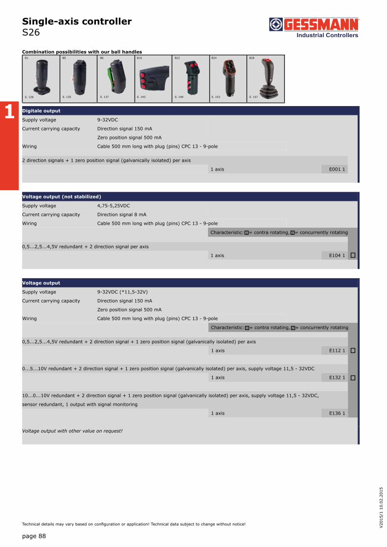
Single-axis controller S26
Combination possibilities with our ball handles
1
page 88
V20
15/1
10.
02.2
015
Technical details may vary based on configuration or application! Technical data subject to change without notice!
Digitale output
Supply voltage 9-32VDC
Current carrying capacity Direction signal 150 mA
Zero position signal 500 mA
Wiring Cable 500 mm long with plug (pins) CPC 13 - 9-pole
2 direction signals + 1 zero position signal (galvanically isolated) per axis
1 axis E001 1
Voltage output (not stabilized)
Supply voltage 4,75-5,25VDC
Current carrying capacity Direction signal 8 mA
Wiring Cable 500 mm long with plug (pins) CPC 13 - 9-pole
Characteristic: 1 = contra rotating, 2 = concurrently rotating
0,5...2,5...4,5V redundant + 2 direction signal per axis
1 axis E104 1
Voltage output
Supply voltage 9-32VDC (*11,5-32V)
Current carrying capacity Direction signal 150 mA
Zero position signal 500 mA
Wiring Cable 500 mm long with plug (pins) CPC 13 - 9-pole
Characteristic: 1 = contra rotating, 2 = concurrently rotating
0,5...2,5...4,5V redundant + 2 direction signal + 1 zero position signal (galvanically isolated) per axis
1 axis E112 1
0...5...10V redundant + 2 direction signal + 1 zero position signal (galvanically isolated) per axis, supply voltage 11,5 - 32VDC
1 axis E132 1
10...0...10V redundant + 2 direction signal + 1 zero position signal (galvanically isolated) per axis, supply voltage 11,5 - 32VDC,
sensor redundant, 1 output with signal monitoring
1 axis E136 1
Voltage output with other value on request!
B1 B5 B6 B10 B22 B24 B28
S. 128 S. 135 S. 137 S. 143 S. 149 S. 153 S. 157

Current output
Supply voltage 9-32VDC
Current carrying capacity Direction signal 150 mA
Zero position signal 500 mA
Wiring Cable 500 mm long with plug (pins) CPC 13 - 9-pole
0...10...20mA redundant + 2 direction signal + 1 zero position signal (galvanically isolated) per axis, sensor redundant,
1 output with signal monitoring
1 axis E206 1
20...0...20mA redundant + 2 direction signal + 1 zero position signal (galvanically isolated) per axis, sensor redundant,
1 output with signal monitoring
1 axis E208 1
4...12...20mA redundant + 2 direction signal + 1 zero position signal (galvanically isolated) per axis, sensor redundant,
1 output with signal monitoring
1 axis E214 1
20...4...20mA redundant + 2 direction signal + 1 zero position signal (galvanically isolated), per axis, sensor redundant,
1 output with signal monitoring
1 axis E216 1
Current output with other value on request!
Attachment
Mating connector AMP CPC 13 9-pole (pins-contact) 5300000479
Mating connector AMP CPC 13 9-pole (pins-contact) with 2 m cable 5300000480
Single-axis controller S26
1
page 89
Technical details may vary based on configuration or application! Technical data subject to change without notice!

Single-axis controller S26
1
T = Dead man's buttonH = Signal buttonM = Latch for mechanical zero interlock
42
Knob solidD= Push button
max
. 4
113
,5
74
T MN
H M
Cover plate IP 54
IP 00
42
70
37,5° 37,5°
45
80
22,50
20,5
3,20
36,5 ±0,2
Hole pattern
145
35
Palm grip B5B5 T = Dead man's button
1 / S26
page 90
V20
15/1
10.
02.2
015
Technical details may vary based on configuration or application! Technical data subject to change without notice!

Single-axis controller S27
1
2
5
6
Identification of the installation variants
with switching directions:
1
page 91
Technical details may vary based on configuration or application! Technical data subject to change without notice!
S27L T - Z - E... - X
Basic unit
S27L left
S27R right
Grip / palm grip
Knob (standard)
M Mechanical zero interlock
Q T-grip
Z Spring return
R Friction brake
Interface (description on the following pages)
E0xx Digital output
E1xx Voltage output
E2xx Current output
Special model
X Special / customer specific
The single-axis controller S27 is a hall sensor switching device designed for electro-hydraulic and remote controlled hydraulic. The modular design of the switching device is universally applicable. The single-axis controller is resistant to oil, maritime conditions e.g. offshore /vessels, UV radiation typically from the sun.
Technical data
Mechanical life S27 6 million operating cycles
Operating temperature -40°C til +60°C
Degree of protection IP 65
S27 left
Example
S27 right

Single-axis controller S27
1
page 92
V20
15/1
10.
02.2
015
Technical details may vary based on configuration or application! Technical data subject to change without notice!
Digital output
Supply voltage 9-32VDC
Current carrying capacity Direction signal 150 mA
Zero position signal 500 mA
Wiring Cable 500 mm long with plug (pins) CPC 13 - 9-pole
2 direction signals + 1 zero position signal (galvanically isolated) per axis
1 axis E001 1
Voltage output (not stabilized)
Supply voltage 4,75-5,25VDC
Current carrying capacity Direction signal 8 mA
Einbautiefe A 60 mm
Wiring Cable 500 mm long with plug (pins) CPC 13 - 9-pole
Characteristic: 1 = contra rotating, 2 = concurrently rotating
0,5...2,5...4,5V redundant + 2 direction signal per axis
1 axis E104 1
Voltage output
Supply voltage 9-32VDC (*11,5-32V)
Current carrying capacity Direction signal 150 mA
Zero position signal 500 mA
Wiring Cable 500 mm long with plug (pins) CPC 13 - 9-pole
Characteristic: 1 = contra rotating, 2 = concurrently rotating
0,5...2,5...4,5V redundant + 2 direction signal + 1 zero position signal (galvanically isolated) per axis
1 axis E112 1
00...5...10V redundant + 2 direction signal + 1 zero position signal (galvanically isolated) per axis, supply voltage 11,5 - 32VDC
1 axis E132 1
10...0...10V redundant + 2 direction signal + 1 zero position signal (galvanically isolated) per axis, supply voltage 11,5 - 32VDC,
sensor redundant, 1 output with signal monitoring
1 axis E136 1
Voltage output with other value on request!

Current output
Supply voltage 9-32VDC
Current carrying capacity Direction signal 150 mA
Zero position signal 500 mA
Wiring Cable 500 mm long with plug (pins) CPC 13 - 9-pole
0...10...20mA redundant + 2 direction signal + 1 zero position signal (galvanically isolated) per axis, sensor redundant,
1 output with signal monitoring
1 axis E206 1
20...0...20mA redundant + 2 direction signal + 1 zero position signal (galvanically isolated) per axis, sensor redundant,
1 output with signal monitoring
1 axis E208 1
4...12...20mA redundant + 2 direction signal + 1 zero position signal (galvanically isolated) per axis, sensor redundant,
1 output with signal monitoring
1 axis E214 1
20...4...20mA redundant + 2 direction signal + 1 zero position signal (galvanically isolated) per axis, sensor redundant,
1 output with signal monitoring
1 axis E216 1
Voltage output with other value on request!
Attachment
Mating connector AMP CPC 13 9-pole (pins-contact) 5300000479
Mating connector AMP CPC 13 9-pole (pins-contact) with 2 m cable 5300000480
Single-axis controller S27
1
page 93
Technical details may vary based on configuration or application! Technical data subject to change without notice!

Single-axis controller S27
1
M = Latch for mechanical zero interlock T - grip
42
140
4
9 36
M
Cover plate IP 65IP 00
70
37,5° 37,5°
84
122
57
72
98,
5
82
5,5or M5
Hole pattern
80
28
140
1 / S27
page 94
V20
15/1
10.
02.2
015
Technical details may vary based on configuration or application! Technical data subject to change without notice!

Single-axis controller S3
The single-axis control S3 is a rugged switching device for hoisting applications. The modular design enables the switching device to be used universally. The single-axis controller is resistant to oil, maritime conditions e.g. offshore /vessels, UV radiation typically from the sun.
Technical data
Mechanical life S3 12 million operating cycles
Operating temperature -40°C til +60°C
Degree of protection IP 66 front
S3L S5 Q - 2 R P - B - A05 P214 - E1291 - X
Basic unit
S3L Single-axis controller left
Control-handle extended
S5 -20 mm
Grip- control-handle left
Q T-grip
Axis 1
2 2 contacts (1,5A 24VDC13)
R Friction brake
P Potentiometer
Cover housing
B Cover housing
Description axis 1 (direction 1-2)
A05 Arrangement MSP 21
P214 Potentiometer T246 2x5 kOhm
Interface
E1291 Voltage output 0...5...10V
Special model
X Special / customer-specific
1
page 95
Technical details may vary based on configuration or application! Technical data subject to change without notice!
Example

Single-axis controller S3
S3L S5 Q - 2 R P - B - A05 P214 - E1291 - X
Basic unit
S3L Single-axis controller, control-handle left Identification of the installation variants
S3R Single-axis controller, control-handle right with switching directions:
Control-handle extended*
Standard 148 mm
S5 -20 mm
S8 +20 mm
*Only possible in combination with handle!
Grip
Knob
D Push button
Q T-grip
QD T-grip with push button side
S3L S5 Q - 2 R P - B - A05 P214 - E1291 - X
Axis 1: direction 1-2 left
1 1 contact Standard contact - arrangement see page 106
2 2 contacts z.B.
3 3 contacts A98
A05
A050
A99 contact - arrangement according customer request
R Friction brake
(P) Possibility of mounting potentiometer and encoder (Gessmann-types)
P Potentiometer P211 T246 2x0,5 kOhm l max. 1 mA
P212 T246 2x1 kOhm l max. 1 mA
P214 T246 2x5 kOhm l max. 1 mA
P215 T246 2x10 kOhm l max. 1 mA
More potentiometer on request!
Hall-Potentiometer P42 T1003
S3L S5 Q - 2 R P - B - A05 P214 - E1291 - X
Cover housing
B Cover housing
Interface (description on the following pages)
Potentiometer output
E1xx Voltage output
E2xx Current output
Special model
X Special / customer-specific
1
2
S3L
3
4
S3R1
page 96
V20
15/1
10.
02.2
015
Technical details may vary based on configuration or application! Technical data subject to change without notice!

Single-axis controller S3
Voltage output
Supply voltage 11,5-32VDC
Wiring Cable 500 mm long with plug (pins) CPC 17 - 14-pole
0...5...10V per axis
1 axis E129 1
10...0...10V per axis
1 axis E141 1
-10...0...+10V per axis
1 axis E140 1
Voltage output with other value on request!
Current output
Supply voltage 18-36VDC
Wiring Cable 500 mm long with plug (pins) CPC 17 - 14-pole
4...12...20 mA per axis
1 axis E209 1
20...4...20 mA per axis
1 axis E217 1
Attachment
Mating connector AMP CPC 13 9-pole (socket-contact) 5300000209
Mating connector AMP CPC 13 9-pole (socket-contact) with 2 m cable 5300000210
1
page 97
Technical details may vary based on configuration or application! Technical data subject to change without notice!

Single-axis controller S3
1
120
80
60° 60°
26
86
67,
5
Cable entryFilter plug
IP 66
IP 00
Cover plate
96
101
25
156
1
03
Adjustment screwfor friction brake
154
Knob solidD= Push button
6
100
84
82
Hole pattern
T - gripD= Push button
1 / 213
page 98
V20
15/1
10.
02.2
015
Technical details may vary based on configuration or application! Technical data subject to change without notice!

Single-axis controller S9
1
page 99
Technical details may vary based on configuration or application! Technical data subject to change without notice!
The single-axis controller S9 is a hallsensor switching device designed for electro- hydraulic applications. Due to its small size, the S9 is particularly suitable for installation in our ball handles. The single-axis controller is resistant to oil, maritime conditions e.g. offshore /vessels, UV radiation typically from the sun.
Technical data
Mechanical life S9 5 million operating cycles
Operating force 1,6 til 3,5N
Supply voltage 5VDC stabilized
Operating temperature -40°C til +60°C
Degree of protection IP 67
S9 - E10311 - X
Basic unit
S9
Interface
Voltage output
E 1031 0,5...2,5...4,5V redundant at Ub=5V 1 axis
characteristic: 1 = contra rotating, 2 = concurrently rotating
Special model
X Special / customer-specific
Example

Single-axis controller S9
1
23,5
max
. 4
12
32
25° 25° 1
9,5
31
Rocker
Cover plate
23,5
22,5
13
R1,5
17,
9 +
0,1
20,6 +0,1
Hole pattern(installed from the top)
1
2
23,5
max
. 4
16,
2
25° 25°
15
31
Rocker
Cover plate
R3,5
3
27,2 ±0,1
20,2 +0,1
19,
2 +
0,1
Hole pattern(installed from below)
chamferingØ5,8 x 90°
22,5
13
1
2
Installed from the top
Installed from below
1/223
page 100
V20
15/1
10.
02.2
015
Technical details may vary based on configuration or application! Technical data subject to change without notice!

Control switch N6
1
page 101
Technical details may vary based on configuration or application! Technical data subject to change without notice!
The control-switch N6 is a rugged switching device for hoisting applications. The modular design enables the switching device to be used universally. The single-axis controller is resistant to oil, maritime conditions e.g. offshore /vessels, UV radiation typically from the sun.
Technical data
Mechanical life N6 10 million operating cycles
Operating temperature -40°C til +60°C
Degree of protection IP 54
N6 - DG - 01 Z P - A05 P134 - X
Basic unit
N6 incl. ISO-front plate 88x88 mm
Grip
DG Twist grip
Axis 1 (direction 2-4)
01 2 contacts (2A 250V AC15)
Z Spring return
P Potentiometer
Description axis 1 (direction 3-4)
A05 Arrangement MSP 21
P134 Potentiometer T396 2x5 kOhm
Special model
X Special / customer-specific
Example

Control switch N6
1
page 102
V20
15/1
10.
02.2
015
Technical details may vary based on configuration or application! Technical data subject to change without notice!
N6 - DG - 01 Z P - A05 P134 - X
Basic unit
N6 incl. ISO-front plate 88x88 mm
N6A incl. ISO-front plate 88x88 mm, IP65 (front)
Grip
KN Knob
HG Ball grip
DG Twist grip
Axis 1: direction 3-4
(Standard contacts gold-plated 2A 250V AC15)
01 2 contacts Standard contact - arrangement see page 106
02 4 contacts z.B.
03 6 contacts A980 MS 00
04 8 contacts A05 MS 21
05 10 contacts A0500 MS 21-00
06 12 contacts A110 MS 24-0
A = silver contacts (4A 250V AC15) A99 contacts - arrangement according customer request
Z Spring return
R Friction brake
(P) Possibility of mounting potentiometer and encoder (Gessmann-types)
P Potentiometer P131 T396 2x0,5 kOhm l max. 1 mA
P132 T396 2x1 kOhm l max. 1 mA
P133 T396 2x2 kOhm l max. 1 mA
P134 T396 2x5 kOhm l max. 1 mA
P135 T396 2x10 kOhm l max. 1 mA
More potentiometer on request!
C C... Encoder see page 118
N6 - DG - 01 Z P - A05 P134 - X
Special model
X Special / customer-specific
Attachment
Indicating label
Indicating label with engraving

Control switch N6
1
CAGE CLAMP® connection max. 2,5mm²
25
44
A
30
33 48
45
Cov
er p
late
1..
.5
PotentiometerT130
21 6
4
108 Ball - handle
44
50
Rotary mechanism
88
,5
79
71
22,5
48
4,5
Hole pattern
Knob
1 / 231
IP 54
IP 00
Type No. of contacts Dim. A Spring
return01 2 53
+25
02 4 65
03 6 78
04 8 90
05 10 103
06 12 115
page 103
Technical details may vary based on configuration or application! Technical data subject to change without notice!
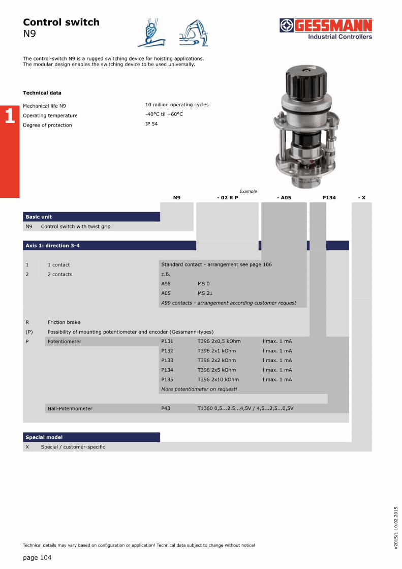
Control switch N9
1
page 104
V20
15/1
10.
02.2
015
Technical details may vary based on configuration or application! Technical data subject to change without notice!
N9 - 02 R P - A05 P134 - X
Basic unit
N9 Control switch with twist grip
Axis 1: direction 3-4
1 1 contact Standard contact - arrangement see page 106
2 2 contacts z.B.
A98 MS 0
A05 MS 21
A99 contacts - arrangement according customer request
R Friction brake
(P) Possibility of mounting potentiometer and encoder (Gessmann-types)
P Potentiometer P131 T396 2x0,5 kOhm l max. 1 mA
P132 T396 2x1 kOhm l max. 1 mA
P133 T396 2x2 kOhm l max. 1 mA
P134 T396 2x5 kOhm l max. 1 mA
P135 T396 2x10 kOhm l max. 1 mA
More potentiometer on request!
Hall-Potentiometer P43 T1360 0,5...2,5...4,5V / 4,5...2,5...0,5V
Special model
X Special / customer-specific
The control-switch N9 is a rugged switching device for hoisting applications. The modular design enables the switching device to be used universally.
Technical data
Mechanical life N9 10 million operating cycles
Operating temperature -40°C til +60°C
Degree of protection IP 54
Example

Control switch N9
61
max
. 6
27
30
38
Einbauplatte
R33,7
30,50
Einbauöffnung
N9
1
61
max
. 6
27
30
38
Cover plate
R33,7
30,50
Hole pattern
N9
page 105
Technical details may vary based on configuration or application! Technical data subject to change without notice!

1
Standard contact-arrangement for master switch
Type Type
0 1
MS 11 ° ° 3 03 A01
0 1 2
° ° 3 03A02MS 12
° ° 2 02
0 1 2 3
° ° 3 03
A03MS 13 ° ° 2 02
° ° 4 04
0 1 2 3 4
° ° 3 03
MS 14 A04° ° 2 02
° ° 4 04
° ° 6 06
1 0 1
° ° 3 03MS 21 A05
° ° 5 05
2 1 0 1 2
° ° 3 03
MS 22 A06° ° 5 05
° ° 2 02
2 1 0 1 2
° ° 3 03
MS 212 A07° ° 5 05
° ° 2 02
° ° 4 04
2 1 0 1 2
° ° 3 03
MS 222 A08° ° 5 05
° ° 2 02
° ° 4 04
Type Type
4 3 2 1 0 1 2 3 4
MS 24
° ° 3 03
A11
° ° 5 05
° ° 2 02
° ° 4 04
° ° 6 06
4 3 2 1 0 1 2 3 4
° ° 3 03
MS 214 A12
° ° 5 05
° ° 2 02
° ° 20 020
° ° 4 04
° ° 40 040
° ° 6 60
° ° 60 060
3 2 1 0 1 2 3
MS 23
° ° 3 03
A09° ° 5 05
° ° 7 07
° ° 9 09
3 2 1 0 1 2 3
MS 213
° ° 3 03
A10
° ° 5 05
° ° 2 02
° ° 20 020
° ° 4 04
° °40 040
4 3 2 1 0 1 2 3 4
MS 224
° ° 3 03
A13° ° 5 05
° ° 2 02
° ° 4 04
5 4 3 2 1 0 1 2 3 4 5
MS 25
° ° 3 03
A14
° ° 5 05
° ° 2 02
° ° 4 04
° ° 6 06
° ° 8 08
6 5 4 3 2 1 0 1 2 3 4 5 6
MS 26
° ° 3 03
A15
° ° 5 05
° ° 2 02
° ° 4 04
° ° 6 06
° ° 8 08
° ° 10 010
0
MS 0 ° ° 0 1 A98
Contact arrangement special
Mechanical zero interlock
Break contact
0
° ° 0 1 A...0
page 106
V20
15/1
10.
02.2
015
Technical details may vary based on configuration or application! Technical data subject to change without notice!

1
Standard contact-arrangement for master switch
Potentiometer MSP
M
A
S
E
Micro change over contact for control handle with dead man`s button signal button push button
contact 5 05 = direction 1/4/5/8
contact 3 03 = direction 2/3/6/7
Deflection directions designated
DIN 15025
2
1 5
3 4 7 8
2 6
left right
4
1
Mechanical zero interlock
Front contact
0
° ° 0 1 A...1
page 107
Technical details may vary based on configuration or application! Technical data subject to change without notice!

1
Ordering information
Customer Order No.
Equipment box left Pos. No.
Type Colour Label text (max. 2 x 12 characters)
Plant ref.
Desti- nation
Notes
1
2
3
4
5
6
7
8
9
10
11
12
13
14
15
16Maximum installation of command and indicating devices 22 (see 1/360) in our control units and housings if our mul-ti-axis controllers V62 (see 1/100) are
used. Additional command and indicating devices can be installed of multi-axis
controllers V64 or V11 (see 1/100) are used. (please enquire)
17
18
19
20
21
22
23
24
Control unit (see 2/030ff.) Type
No. of pieces max.
KST 3 1 - 6, 8 - 13, 15 - 18 16
KST 41/181 1 - 5, 10 - 12 8
KST 42/182 1 - 5, 8 - 12, 15 - 17 13
KST 51/151 3 - 7, 10 - 14, 15 - 19, 20 - 24 20
KST 52/53/54/152/154 1 -24 24
KST 6 3 - 4, 10 - 11, 15 - 16 6
KST 7 1 - 24 24
KST 75 1 - 19 19
1
2
3
4
5
6
7
10
9
8
1
4
2
3
11
12
13
14
15
16
17
18
19
20
21
22
23
24
page 108
V20
15/1
10.
02.2
015
Technical details may vary based on configuration or application! Technical data subject to change without notice!
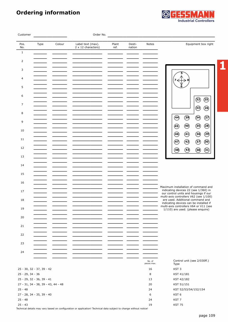
1
Ordering information
Customer Order No.
Pos. No.
Type Colour Label text (max). 2 x 12 characters)
Plant ref.
Desti- nation
Notes Equipment box right
1
2
3
4
5
6
7
8
9
10
11
12
13
14
15
16Maximum installation of command and indicating devices 22 (see 1/360) in our control units and housings if our
multi-axis controllers V62 (see 1/100) are used. Additional command and indicating devices can be installed if
multi-axis controllers V64 or V11 (see 1/110) are used. (please enquire)
17
18
19
20
21
22
23
24
No. of pieces max.
Control unit (see 2/030ff.) Type
25 - 30, 32 - 37, 39 - 42 16 KST 3
25 - 29, 34 - 36 8 KST 41/181
25 - 29, 32 - 36, 39 - 41 13 KST 42/182
27 - 31, 34 - 38, 39 - 43, 44 - 48 20 KST 51/151
25 - 48 24 KST 52/53/54/152/154
27 - 28, 34 - 35, 39 - 40 6 KST 6
25 - 48 24 KST 7
25 - 43 19 KST 75
32 25
33 26
44 39 34 27
45 40
46
47
48 43
42
41
35
36
37
38 31
30
29
28
5
8
6
7
page 109
Technical details may vary based on configuration or application! Technical data subject to change without notice!

1
Ordering information KST 8, 85
Customer Order No.
Equipment box left Pos. No.
Type Colour Lable text (max). 2 x 12 characters)
Plant ref.
Desti-nation
Notes
Max. 6 pcs. installation of command and indicating de-vices 22 (see 1/360) or 1 pcs. monito-ring device 72 x 72 mm
1
2
3
4
5Multi-axis controller V64 (see 1/100) or V11 (see 1/110)
6
7
8
Max. 3 pcs. installation of command and indicating de-vices 22 (see 1/360)
9
10
11
Place to put on devices
12
Equipment box right
Max. 6 pcs. installation of command and indicating de-vices 22 (see 1/360) or 1 pcs. monito-ring device 72 x 72 mm
13
14
15
16
17Multi-axis controller V64 (see 1/100) or V11 (see 1/110)
18
19
20
Max. 3 pcs. installaion of command and indicatin de-vices 22 (see 1/360)
21
22
23
Place to put on devices
24
19
1 3 5
2 4 6
1
4
2
3
13 15 17
14 16 18
5
6
87
20 21
page 110
V20
15/1
10.
02.2
015
Technical details may vary based on configuration or application! Technical data subject to change without notice!

1
Ordering information KST 10
Customer Order No.
Equipment box left Pos. No.
Type Colour Label text (max). 2 x 12 characters)
Plant ref.
Desti-nation
Notes
1
Max. 3 pcs. installation of command and indicating devices 22 (see 1/360)
2
3
4
5
6Multi-axis con-troller V11, V14, V25, V85 (see 1/110ff)
7
8
9
Max. 3 pcs. installation of command and indicating devices 22 (see 1/360)
Equipment box right
13
Max. 3 pcs. installation of command and indicating devices 22 (see 1/360)
14
15
16
17
18Multi-axis con-troller V11, V14, V25, V85 (see 1/110ff)
Max. 3 pcs. installation of command and indicating devices 22 (see 1/360)
2 31
1
43
2
4 5 6
10 11 12
13 14 15
5
8
6
7
page 111
Technical details may vary based on configuration or application! Technical data subject to change without notice!

1
Order information KST 19
Customer Order No.
Equipment box left Pos. No.
Type Colour Label text (max). 2 x 12 characters)
Plant- ref.
Desti-nation
Notes
Multi-axis controller V11, V14, V25, V85 see 1/11 0ff.
1
2max. 7 installations of command and indicating devices 22 (see 1/360) 3
4
5
6
7
8
9
Equipment box right
Multi-axis controller V11, V14, V25, V85 see 1/110ff.
25
26max. 7 installations of command and indicating devices 22 (see 1/360) 27
28
29
30
31
1
4
2
37
6
5
43
2
1
+
+
+
+
+
+
+
+
+
+
+
+
++
+25
26 27
28
29
30
31
+
5
8
6
7
page 112
V20
15/1
10.
02.2
015
Technical details may vary based on configuration or application! Technical data subject to change without notice!

1
Technical data
page 113
Technical details may vary based on configuration or application! Technical data subject to change without notice!
Utilization categories for control switches to IEC/EN 60947-5-1
Type of current
Utilization category Typical examples of application Normal conditions of use
I= current made, Ic= current broken Ie= rated operational current, U= voltage before make Ue= rated operational voltageUr= recovery voltage T 0,95= time in ms, to reach 95% of the steady-state current. P= UE ∙ Ie= steady-state power consumption in watts
Make
I U — — le Ue
cos
Breake
Ic Ur — — le Ue
cos
alternating current
AC12
AC15
Control of resistive loads and solid state loads with isolation by opto couplers control of a.c. electromagnetic loads (> 72 VA)
1
10
1
1
0,9
0,3
1
1
1
1
0,9
0,3
I —
le
U —
Uet 0,95
lc —
le
Ur —
Uet 0,95
Direct current
DC 12
DC 13
Control of resistive loads and solid state loads with isola-tion by opto couplers Control of d.c. electromagnets
1
1
1
1
1 ms
6 ∙ P
1
1
1
1
1 ms
6 ∙ P
The value 6·P results from an empirical relationship with is found to represent most d.c. magnetic loads to an upper limit of P = 50 W viz 6·P = 300 ms. Loads having power consumption greater than 50 W are assumed to consist of smaller loads in parallel. Therefore 300 ms is to be an upper limit, irrespective of the power consumption value.
Attach our switching device
V6 N6S6N61 N62
VV6DD64
V11 V5S2-S23
VV5SS2-SS21
Rated isolation voltage Ui in Volt 250 250 250 250 250
Rated operational voltage Ue in Volt 250 250 250 250 250
Rated operational voltage le in Ampere AC 12 6 or 16 6 or 16 6 or 16 10 10
AC 15 2 4 2 4 2 4 2 2
DC 12 24 V 6 8 6 8 6 8 4 4
48V 2 4 2 4 2 4 2 2
110V 0,5 1 0,5 1 0,5 1 0,2 0,2
220V 0,1 0,5 0,1 0,5 0,1 0,5 0,1 0,1
Contacts gold-coated 24V 5 mA 5 mA 5 mA 5 mA 5 mA
DC 13 24V 1 1 1 3 3
48V 0,5 0,5 0,5 1,5 1,5
110V 0,2 0,2 0,2 0,1 0,1
220V 0,05 0,05 0,05 0,05 0,05
Short-circuit-protection in AmpereFuse 9L Circuit-breaker G-characteristic
6 166 16
6 66 16
6 166 16
1010
1010
Terminal screwsPlug-in connector CAGE CLAMP® connection is a registered trademarkt of WAGO Kontakttechnik GmbH Germany
M 3,5
2,5mm²
M 3,5
2,5mm²
M 3,5
2,5mm²
M 3,5
6,3x0,8
M3,5
6,3x0,8
Conductor sizes in mm² finely stranded with end steeves 1,5 1,5 1,5 1,5 1,5
Mechanical life in million (operation cycles) max. switching frequency c/h 1000
10 20 10 6 10
Mechanical shock resistance IEC 68-2-27 Shock-amplitude > 15 Shock duration 20 ms
Clearances and creepage distances IEC 947-1; 2.5.46.51
Overvoltage category III pollution grade 3
Degree of protection to IEC/EN 60529
1. numerial protection of contact and foreign bodies
2. numerial protection of water
IP00 No protection No protection
IP54 Protection deposits of dust Protection splashing of water
IP65 Protection complete of dust Protection hosed of water
IP66 Protection complete of dust Protection hosed strong of water
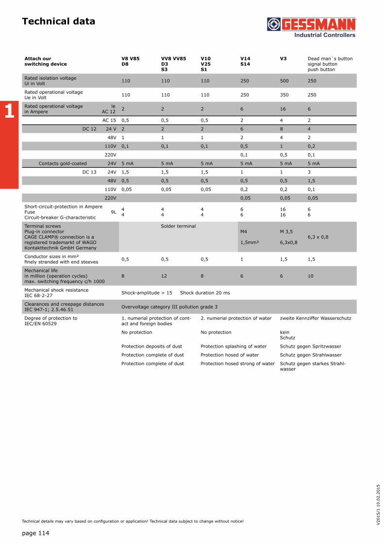
1
Technical data
page 114
V20
15/1
10.
02.2
015
Technical details may vary based on configuration or application! Technical data subject to change without notice!
Attach our switching device
V8 V85D8
VV8 VV85D3S3
V10V25S1
V14S14
V3 Dead man`s button signal button push button
Rated isolation voltage Ui in Volt 110 110 110 250 500 250
Rated operational voltage Ue in Volt 110 110 110 250 350 250
Rated operational voltage le in Ampere AC 12 2 2 2 6 16 6
AC 15 0,5 0,5 0,5 2 4 2
DC 12 24 V 2 2 2 6 8 4
48V 1 1 1 2 4 2
110V 0,1 0,1 0,1 0,5 1 0,2
220V 0,1 0,5 0,1
Contacts gold-coated 24V 5 mA 5 mA 5 mA 5 mA 5 mA 5 mA
DC 13 24V 1,5 1,5 1,5 1 1 3
48V 0,5 0,5 0,5 0,5 0,5 1,5
110V 0,05 0,05 0,05 0,2 0,2 0,1
220V 0,05 0,05 0,05
Short-circuit-protection in AmpereFuse 9L Circuit-breaker G-characteristic
44
44
44
66
1616
66
Terminal screwsPlug-in connector CAGE CLAMP® connection is a registered trademarkt of WAGO Kontakttechnik GmbH Germany
Solder terminalM4
1,5mm²
M 3,5
6,3x0,86,3 x 0,8
Conductor sizes in mm² finely stranded with end steeves 0,5 0,5 0,5 1 1,5 1,5
Mechanical life in million (operation cycles) max. switching frequency c/h 1000
8 12 8 6 6 10
Mechanical shock resistance IEC 68-2-27 Shock-amplitude > 15 Shock duration 20 ms
Clearances and creepage distances IEC 947-1; 2.5.46.51 Overvoltage category III pollution grade 3
Degree of protection to IEC/EN 60529
1. numerial protection of cont-act and foreign bodies
2. numerial protection of water zweite Kennziffer Wasserschutz
No protection No protection kein Schutz
Protection deposits of dust Protection splashing of water Schutz gegen Spritzwasser
Protection complete of dust Protection hosed of water Schutz gegen Strahlwasser
Protection complete of dust Protection hosed strong of water Schutz gegen starkes Strahl-wasser