section 1: executive section 7: conceptual summary...
TRANSCRIPT

Section 1: Executive Summary
Section 7C
onceptual Design
Section 7: Conceptual Design & Costing

7-1
SECTION 7: CONCEPTUAL DESIGN AND COSTING
7.1 SECTION PURPOSE
This section presents the process used to complete the conceptual design and costing used to evaluate the multiple of alternatives that were considered to reach final selection of the preferred project alternatives. In order to calculate and compare the economics of the various route options, estimates were completed for each of the line segments individually and then combined to form a route option estimate. Rather than default to a common cost per mile assumption for the different voltages, the estimates were built from the bottom up, starting with a conceptual design and incorporating the appropriate unit costs. The major advantage of completing the estimates in this manner is that they take the constraints identified through the mapping effort into account, yielding estimates that more closely reflect the actual field conditions. A second advantage is that as the project becomes more refined, the cost estimate can be easily updated to reflect the latest information available. Conceptual design and costing was also completed for each of the substation projects that would be required for the various alternatives in order to reach a final cost evaluation.
7.2 TRANSMISSION LINE CONCEPTUAL DESIGN
The transmission line cost estimates used in this study are based on a conceptual design. The conceptual design was completed in PLS-CADD and the results were exported to an Excel spreadsheet to complete the estimating process. Completion of the conceptual design followed the following steps:
1. Alignment: As discussed in Section 6, multiple route options and alignment segments were considered. Once the segments were established, they were imported into the model to begin the conceptual design process.
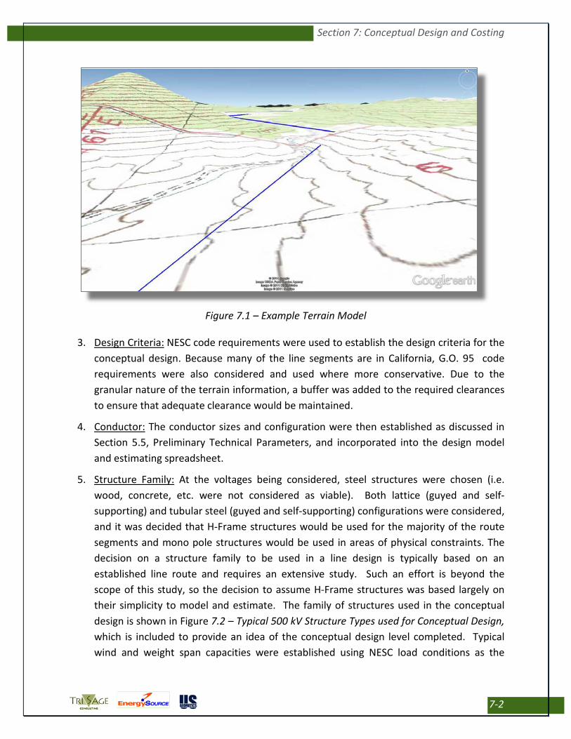
2. Terrain: For this conceptual level of design, a digital terrain model was imported from the National Elevation Dataset. This data is based on a grid spaced at 10 meters and is therefore not accurate enough for a detailed final design. It is, however, adequate for use in conceptual designs for study purposes. An example model with the USGS topographic map “draped” over the terrain and the alignment shown in blue is depicted in Figure 7.1 – Example Terrain Model.
Section 7: Conceptual Design and Costing
7-2
Figure 7.1 – Example Terrain Model
3. Design Criteria: NESC code requirements were used to establish the design criteria for the conceptual design. Because many of the line segments are in California, G.O. 95 code requirements were also considered and used where more conservative. Due to the granular nature of the terrain information, a buffer was added to the required clearances to ensure that adequate clearance would be maintained.
4. Conductor: The conductor sizes and configuration were then established as discussed in Section 5.5, Preliminary Technical Parameters, and incorporated into the design model and estimating spreadsheet.
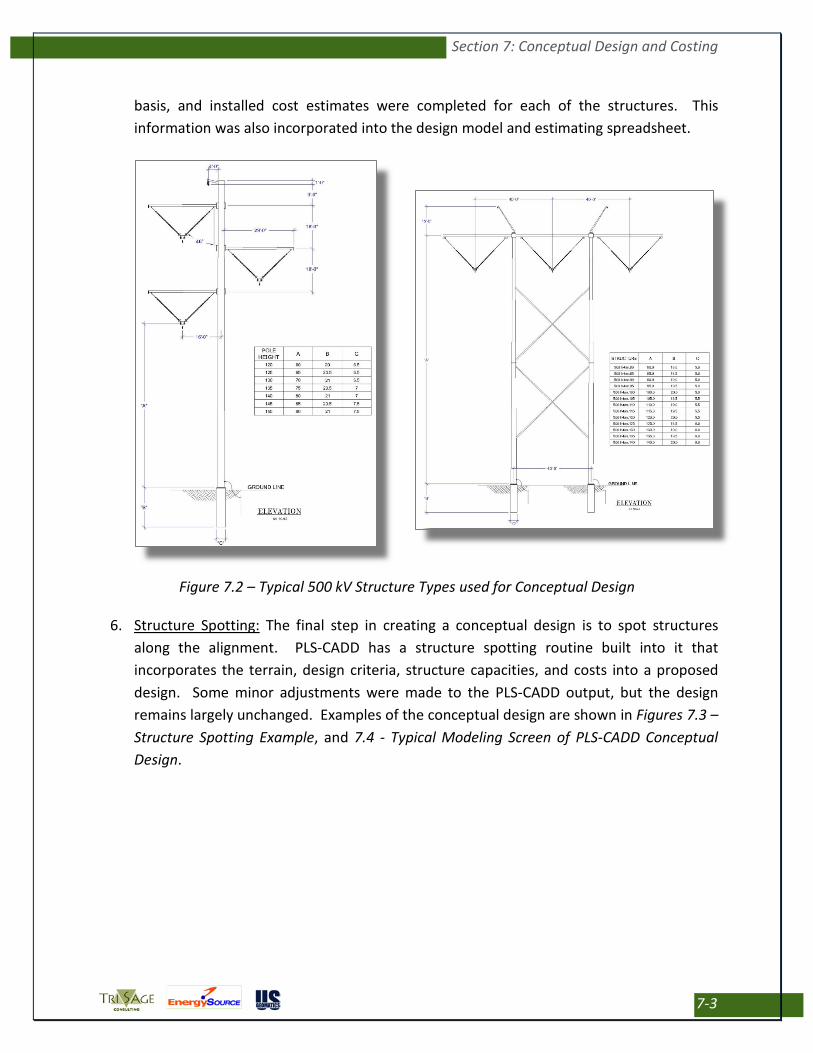
5. Structure Family: At the voltages being considered, steel structures were chosen (i.e. wood, concrete, etc. were not considered as viable). Both lattice (guyed and self-supporting) and tubular steel (guyed and self-supporting) configurations were considered, and it was decided that H-Frame structures would be used for the majority of the route segments and mono pole structures would be used in areas of physical constraints. The decision on a structure family to be used in a line design is typically based on an established line route and requires an extensive study. Such an effort is beyond the scope of this study, so the decision to assume H-Frame structures was based largely on their simplicity to model and estimate. The family of structures used in the conceptual design is shown in Figure 7.2 – Typical 500 kV Structure Types used for Conceptual Design, which is included to provide an idea of the conceptual design level completed. Typical wind and weight span capacities were established using NESC load conditions as the
Section 7: Conceptual Design and Costing
7-3
basis, and installed cost estimates were completed for each of the structures. This information was also incorporated into the design model and estimating spreadsheet.
Figure 7.2 – Typical 500 kV Structure Types used for Conceptual Design
6. Structure Spotting: The final step in creating a conceptual design is to spot structures along the alignment. PLS-CADD has a structure spotting routine built into it that incorporates the terrain, design criteria, structure capacities, and costs into a proposed design. Some minor adjustments were made to the PLS-CADD output, but the design remains largely unchanged. Examples of the conceptual design are shown in Figures 7.3 – Structure Spotting Example, and 7.4 - Typical Modeling Screen of PLS-CADD Conceptual Design.

Section 7: Conceptual Design and Costing
7-4
Figure 7.3 – Structure Spotting Example
Figure 7.4 – Typical Modeling Screen of PLS-CADD Conceptual Design

Section 7: Conceptual Design and Costing
7-5
7.3 TRANSMISSION LINE COSTING
Results from the conceptual design process yielded the structure and wire quantities and were exported from PLS-CADD to an Excel spreadsheet for final estimating purposes. These quantities were multiplied by material and labor unit costs giving the installed cost for the physical facilities. This comprises the majority of the cost to build the line, but the following “other” costs are necessary to be included to complete the overall project estimates.
• Project Management: Project Management fees for a team engaged in managing the project cost and schedule from development through in-service. These fees also include a consultant engaged in managing public and government relationships.
• Permitting: Permitting costs for consulting and agency fees associated with completing the NEPA process and other federal permits as required; completing the CEQA process (California only) and other jurisdictional permits as required including local, state, and UEPA permits; dealing with constraint impacts during the permitting process; obtaining crossing permits (Highway, Rail-Road, Utilities, etc.); and monitoring the construction process for compliance with the permit conditions.
• Right of Way Acquisition: Right of Way Acquisition costs for document research, surveying, mapping, and coordination fees associated with private rights-of-way acquisition; consultant, appraisal, and legal fees associated with negotiating easements on private lands; and fees paid to private land owners for easements across their property. For the purposes of this study, BIA lands were treated as private property.
• Engineering and Construction Management: Engineering fees to finalize the routing and conceptual design such that permit applications can be completed; surveying and mapping fees associated with completing the final design and supporting the permitting process; engineering fees associated with supporting the permitting and right-of-way acquisition processes; engineering fees associated with completing the detailed design and producing bid/construction packages; engineering fees associated with supporting the bid, award, and construction processes; surveying fees associated with staking structures, anchors, and offsets for construction; and construction manager fees associated with bidding/awarding the project, managing the construction cost and schedule, and maintaining the quality assurance program.
• Construction: Construction contractors’ fees for project management and quality control; for ordering and managing all materials used to construct the project; for bonding and insurance as required by the construction contract; for building permits normally obtained by the construction contractor (e.g. Dust Control); for the cost to mobilize and demobilize the construction crews and equipment to the project base location; for the cost to build

Section 7: Conceptual Design and Costing
7-6
access roads to the structure locations; for the cost to clear the right-of-way and/or trim/remove trees from the right-of-way; for the construction cost associated with establishing and maintaining BMP and other measures necessary to comply with the permit to construct; and for the construction cost associated with mitigating environmental conditions and restoring the right-of-way in accordance with the permit to construct.
Each of these items were assigned the appropriate unit (e.g. each, per acre, per mile, etc.), based on the GIS data and a unit cost for estimating. The data was incorporated into the Excel spreadsheet and the results were totaled along with the structure and wire costs to produce an overall segment cost. The segment costs were then combined to produce an overall cost estimate for each of the route options. Because of the preliminary nature of the data used in producing these estimates, a contingency factor was also added. Estimating results for the Preferred Route options are summarized in Table 7.1 – Preferred Routes – Transmission Costs Summary.

Section 7: Conceptual Design and Costing
7-7
Table 7.1 – Preferred Routes – Transmission Costs Summary

Section 7: Conceptual Design and Costing
7-8
7.4 SUBSTATION CONCEPTUAL LAYOUTS & COSTING
During the course of this transmission routing effort, a conceptual review of both existing and proposed substations was also completed. Conceptual layout of the proposed substation additions was completed in the form of one-line diagrams to allow for preliminary routing, costing and evaluation. These one-lines were completed with consideration of avoiding “and” pricing for wheeling charges. A thorough evaluation of each substation interconnection will be required in the final design effort and will involve each substation owner, as well as grid operator. This effort will likely either be completed concurrently with the WECC path rating process, or immediately on the heels of that effort. This effort is discussed in Section 9 of this report.
Note that the purpose of preparing the one-line diagrams was to support the development of preliminary cost estimates for the substation facilities associated with the proposed projects. The following substations are included as components of the proposed projects. Cost estimates for these substations are summarized in Table 7.2 – Substation Cost Estimates Summary.
7.4.1 North Project Substations
7.4.1.1 North Fernley Substation
North Fernley is a new 345 kV substation in the area north of Fernley, Nevada where the Pacific DC Intertie and the Valmy-Tracy 345 kV lines cross. The project requires folding one or both of the Valmy-Tracy 345 kV lines into the new substation. The North Project has two alternatives; the North Fernley Substation is included in Alternative 1. The one-line diagram and associated cost estimate assumes only one of the Valmy-Tracy 345 kV lines is folded into and out of the substation. The facilities at North Fernley Substation are estimated at approximately $16.0 million.
Figure 7.5 – Conceptual Layout of North Fernley Substation

Section 7: Conceptual Design and Costing
7-9
7.4.1.2 Oreana Substation
Oreana Substation is a proposed 345 kV substation approximately 15 miles northeast of Lovelock, Nevada. NV Energy’s RTI includes the initial construction of the Oreana 345 kV Substation. The North Project has two alternatives; the Oreana Substation is included in Alternative 2. North Project facility additions at Oreana Substation are estimated at approximately $8.9 million.
Figure 7.6 – Conceptual Layout of Oreana Substation
7.4.1.3 San Emidio Substation
San Emidio Substation is a future collector substation for renewable generation approximately 21 miles south of Gerlach, Nevada. This report assumes all improvements at San Emidio Substation would be funded by the renewable generation developers necessitating the facility. As a result, the $64.0 million estimate for San Emidio Substation is not added into the total estimate for the North Project.

Section 7: Conceptual Design and Costing
7-10
Figure 7.7 – Conceptual Layout of San Emidio Substation
7.4.1.4 Viewland Substation
Viewland Substation is a proposed 345 kV substation approximately 40 miles northeast of Susanville, California, on the Alturas Intertie.
Two cost estimates and associated one-line diagrams are included for Viewland Substation. The first cost estimate assumes the Viewland-Olinda project has not been built, so Viewland substation must be built from a Greenfield site; the associated cost estimate is $16.1 million.
Figure 7.8 – Conceptual Layout of Viewland Substation - without LMUD Project

Section 7: Conceptual Design and Costing
7-11
The second cost estimate for the North Project assumes the Viewland Substation has been developed with the Viewland-Olinda project; the Viewland Substation improvements associated with the North Project are estimated at $12.9 million.
Figure 7.9 – Conceptual Layout of Viewland Substation - with LMUD Project
The North Project will also require the relocation of the Bordertown phase shifting transformer to Hilltop Substation. This relocation is estimated at approximately $3.2 million.
7.4.2 East Project Substations
7.4.2.1 Robinson Summit Substation
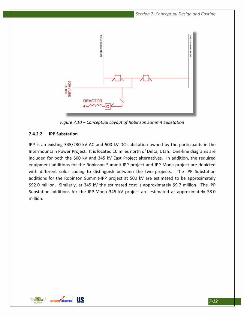
Robinson Summit Substation is a 500/345 kV substation presently under construction as part of the ON Line project. It is located approximately 17 miles northwest of Ely, Nevada. Information detailing the electrical equipment configuration at Robinson Summit Substation following completion of the ON Line Project was unavailable. The one-line diagram for Robinson Summit Substation depicts worst case assumptions with regard to the equipment required for the East Project. The Robinson Summit Substation improvements associated with the East Project are estimated at approximately $13.0 million for a 345 kV project and approximately $ 17.9 million for a 500 kV project.
Section 7: Conceptual Design and Costing
7-12
Figure 7.10 – Conceptual Layout of Robinson Summit Substation
7.4.2.2 IPP Substation
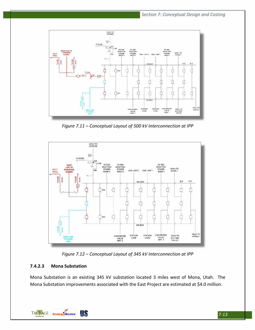
IPP is an existing 345/230 kV AC and 500 kV DC substation owned by the participants in the Intermountain Power Project. It is located 10 miles north of Delta, Utah. One-line diagrams are included for both the 500 kV and 345 kV East Project alternatives. In addition, the required equipment additions for the Robinson Summit-IPP project and IPP-Mona project are depicted with different color coding to distinguish between the two projects. The IPP Substation additions for the Robinson Summit-IPP project at 500 kV are estimated to be approximately $92.0 million. Similarly, at 345 kV the estimated cost is approximately $9.7 million. The IPP Substation additions for the IPP-Mona 345 kV project are estimated at approximately $8.0 million.
Section 7: Conceptual Design and Costing
7-13
Figure 7.11 – Conceptual Layout of 500 kV Interconnection at IPP
Figure 7.12 – Conceptual Layout of 345 kV Interconnection at IPP
7.4.2.3 Mona Substation
Mona Substation is an existing 345 kV substation located 3 miles west of Mona, Utah. The Mona Substation improvements associated with the East Project are estimated at $4.0 million.

Section 7: Conceptual Design and Costing
7-14
Figure 7.13 – Conceptual Layout of Mona Substation
7.4.3 South Project Substations
7.4.3.1 Anaconda-Moly Substation
Anaconda-Moly is an existing 230/120 kV substation on the NV Energy system. It is located approximately 18 miles north of Tonopah, Nevada. The following one-line diagram depicts Anaconda-Moly Substation. Those facilities color coded in black are existing and are not included in cost estimates for the South Project. The facilities color coded in red are new additions associated with the South Project and are included in the South Project cost estimates. South Project facility additions at Anaconda-Moly Substation are estimated at approximately $12.1 million. These improvements are only required if the RTI “West Tie-South” is not built prior to or in conjunction with the South Project.

Section 7: Conceptual Design and Costing
7-15
Figure 7.14 – Conceptual Layout of Anaconda-Moly Substation
7.4.3.2 Clayton Substation
Clayton Substation is a new 500/230 kV substation approximately 26 miles southwest of Tonopah, Nevada. Clayton Substation is only required if the RTI “West Tie-South” line is not built prior to or in conjunction with the South Project. The facilities are broken up into two groupings for cost estimating purposes; 1) Initial construction and 2) Future line to Pahrump. The initial construction of Clayton Substation is estimated at approximately $75.4 million. The future improvements at Clayton Substation for a 500 kV line to Pahrump are estimated at approximately $17.7 million.
Figure 7.15 – Conceptual Layout of 500 kV Interconnection at Clayton Substation
Section 7: Conceptual Design and Costing
7-16
Figure 7.16 – Conceptual Layout of Interconnection at Clayton Sub; Continuation to Pahrump Sub
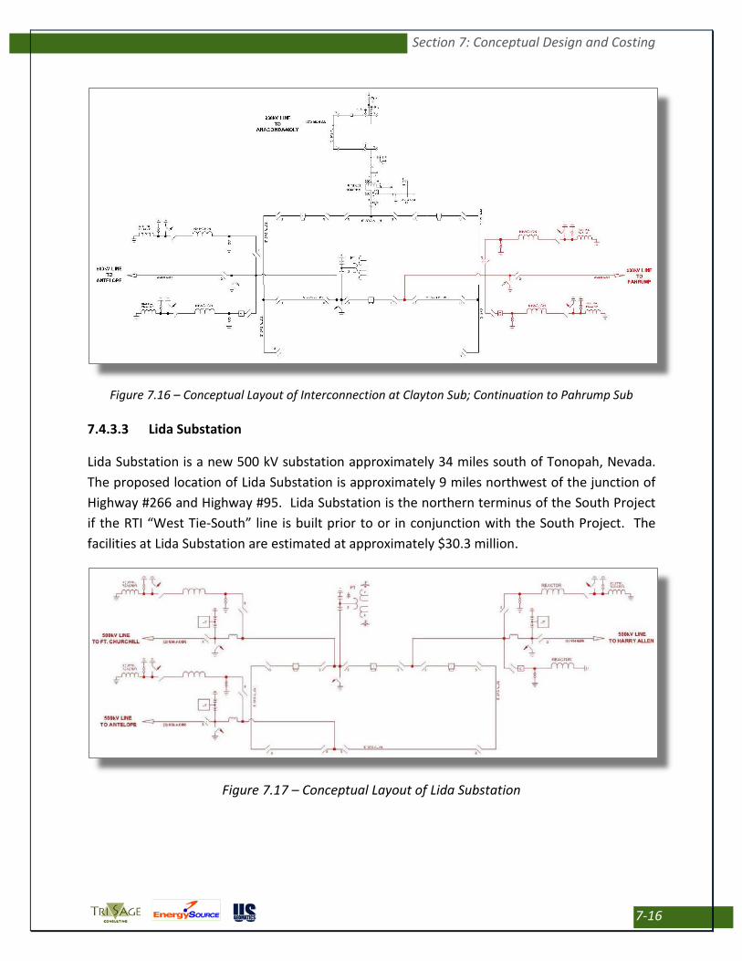
7.4.3.3 Lida Substation
Lida Substation is a new 500 kV substation approximately 34 miles south of Tonopah, Nevada. The proposed location of Lida Substation is approximately 9 miles northwest of the junction of Highway #266 and Highway #95. Lida Substation is the northern terminus of the South Project if the RTI “West Tie-South” line is built prior to or in conjunction with the South Project. The facilities at Lida Substation are estimated at approximately $30.3 million.
Figure 7.17 – Conceptual Layout of Lida Substation

Section 7: Conceptual Design and Costing
7-17
7.4.3.4 Ridgecrest Substation
Ridgecrest Substation is a future collector substation for renewable generation approximately 12 miles northwest of Ridgecrest, California. This report assumes all improvements at Ridgecrest Substation would be funded by the renewable generation developers necessitating the facility. As a result, the $42.0 million estimate for Ridgecrest Substation is not included into the initial cost estimate for evaluation, but is referenced herein for informational purposes.
Figure 7.18 – Conceptual Layout of Ridgecrest Substation
7.4.3.5 Antelope Substation
Antelope is an existing 500/230 kV substation on the Southern California Edison system. It is located approximately 8 miles west of Lancaster, California. No information is readily available with regard to the existing electrical configuration at Antelope Substation. The one-line depicts the electrical equipment that is included in the cost estimate. The required additional facilities at Antelope Substation are estimated at approximately $10.9 million.

Section 7: Conceptual Design and Costing
7-18
Figure 7.19 – Conceptual Layout of Antelope Substation
7.4.3.6 Pahrump Substation
Pahrump is a proposed VEA 500 kV substation. The proposed electrical configuration is unknown. The one-line depicts the electrical equipment that is included in the cost estimate. The required additional facilities at Pahrump Substation are estimated at approximately $17.9 million.
Figure 7.20 – Conceptual Layout of Pahrump Substation

Section 7: Conceptual Design and Costing
7-19
Table 7.2 – Substation Cost Estimates Summary