section 10 chapter 17 - dmcpubs.com · 24 valve, 8.3 liter engine page b air intake system...
TRANSCRIPT

Section 10 Chapter 17
7-89460NH
24 Valve, 8.3 Liter Engine
Air Intake System
Note: All coding used in the 8.3 Liter and 9 Liter engine manuals are Cummins engine codes. These engine codes have no meaning to New Holland warranty codes and should only be used for procedure
steps.


24 Valve, 8.3 Liter EngineAir Intake System Page a
7-89460NH Section 10 Chapter 17 Issued 8-2001
Air Intake System
Contents
Air Crossover (010-019) ................................................................................................................................................................................. 7Inspect for Reuse (010-019-007) ..................................................................................................................................................... 7Install (010-019-026) ........................................................................................................................................................................ 7Remove (010-019-002) .................................................................................................................................................................... 7
Air Inlet Connection (010-022) ...................................................................................................................................................................... 7Install (010-019-026) ........................................................................................................................................................................ 8Remove (010-022-002) .................................................................................................................................................................... 7
Air Intake Manifold (010-023) ........................................................................................................................................................................ 8Clean (010-023-006) ........................................................................................................................................................................ 9Inspect for Reuse (010-023-007) ..................................................................................................................................................... 9Install (010-023-026) ........................................................................................................................................................................ 9Preparatory (010-023-000) ............................................................................................................................................................... 8Remove (010-023-002) .................................................................................................................................................................... 8
Air Intake Restriction (010-031) .................................................................................................................................................................. 17Measure (010-031-010) ................................................................................................................................................................. 17
Air Intake System - General Information ..................................................................................................................................................... 1
Air Leaks, Air Intake and Exhaust Systems (010-024) .............................................................................................................................. 10Initial Check (010-024-001) ............................................................................................................................................................ 10
Boost Pressure (010-057) ............................................................................................................................................................................ 31Measure (010-057-010) ................................................................................................................................................................. 31
Charge Air Cooler (CAC) (010-027) ............................................................................................................................................................ 15Clean (010-027-006) ...................................................................................................................................................................... 15Inspect for Reuse (010-027-007) ................................................................................................................................................... 16
Cold Starting Aid (010-029) ......................................................................................................................................................................... 16Clean (010-029-006) ...................................................................................................................................................................... 17Install (010-029-026) ...................................................................................................................................................................... 17Remove (010-029-002) .................................................................................................................................................................. 16
Flow Diagram, Air In take System ................................................................................................................................................................ 5
Specifications ................................................................................................................................................................................................. 6Air Intake System ............................................................................................................................................................................. 6
Turbocharger (010-033) ............................................................................................................................................................................... 19Clean (010-033-006) ...................................................................................................................................................................... 20Inspect for Reuse (010-033-007) ................................................................................................................................................... 20Install (010-033-026) ...................................................................................................................................................................... 22Remove (010-033-002) .................................................................................................................................................................. 19
Turbocharger Axial Clearance (010-038) ................................................................................................................................................... 23Measure (010-038-010) ................................................................................................................................................................. 23
24 Valve, 8.3 Liter EnginePage b Air Intake System
7-89460NH Section 10 Chapter 17 Issued 8-2001
Turbocharger Blade Damage (010-039) ..................................................................................................................................................... 24Inspect for Reuse (010-039-007) ................................................................................................................................................... 24
Turbocharger Compressor Seal Leaks (010-040) ..................................................................................................................................... 25Leak Test (010-040-014) ............................................................................................................................................................... 25
Turbocharger Oil Drain Line (010-045) ...................................................................................................................................................... 25Clean (010-045-006) ...................................................................................................................................................................... 26Initial Check (010-045-001) ............................................................................................................................................................ 25Inspect for Reuse (010-045-007) ................................................................................................................................................... 26Install (010-045-026) ...................................................................................................................................................................... 26Remove (010-045-002) .................................................................................................................................................................. 26
Turbocharger Oil Supply Line (010-046) .................................................................................................................................................... 27Initial Check (010-046-001) ............................................................................................................................................................ 27Inspect for Reuse (010-046-007) ................................................................................................................................................... 27Install (010-046-026) ...................................................................................................................................................................... 27Remove (010-046-002) .................................................................................................................................................................. 27
Turbocharger Radial Bearing Clearance (010-047) .................................................................................................................................. 28Measure (010-047-010) ................................................................................................................................................................. 28
Turbocharger Wastegate Actuator (010-050) ............................................................................................................................................ 29Initial Check (010-050-001) ............................................................................................................................................................ 29Test (010-050-012) ........................................................................................................................................................................ 30
Turbocharger Wastegate Valve Body (010-055) ....................................................................................................................................... 31Maintenance Check (010-055-008) ............................................................................................................................................... 31

24 Valve, 8.3 Liter Engine Air Intake System - General InformationAir Intake System Page 1
7-89460NH Section 10 Chapter 17 Issued 8-2001
Air Intake System - General Informa-tion
The combustion air system on the 24 Valve, 8.3 Liter en-gine consists of an air cleaner, intake air piping, turbo-charger, charge air piping, charge air cooler (CAC), andintake air heater.
Air is drawn through the air cleaner into the compressorside of the turbocharger (1). It is then forced through theCAC piping (2) to the CAC (3), the intake air heater (if ap-plicable), and into the intake manifold (4). From the intakemanifold, air is forced into the cylinders (5) and used forcombustion.
The turbocharger uses exhaust gas energy to turn the tur-bine wheel. The turbine wheel drives the compressor im-peller which provides pressurized air to the engine forcombustion. The additional air provided by the turbo-charger allows more fuel to be injected to increase thepower output from the engine.
The turbine, compressor wheels, and the shaft are sup-ported by two rotating bearings in the bearing housing.Passages in the bearing housing direct filtered, pressur-ized engine oil to the shaft bearings and thrust bearings.The oil is used to lubricate and cool the rotating compo-nents. Oil then drains from the bearing housing to the en-gine sump through the oil drain line.
� CAUTION �A restricted oil drain line can cause the turbochargerbearing housing to be pressurized, causing oil to leakpast the seal rings.
NOTE: An adequate supply of good, filtered oil is very im-portant to the life of the turbocharger. Make sure that ahigh quality oil is used and that it and the oil filter arechanged according to maintenance recommendations.

Air Intake System - General Information 24 Valve, 8.3 Liter EnginePage 2 Air Intake System
7-89460NH Section 10 Chapter 17 Issued 8-2001
� CAUTION �The turbocharger is a performance part and must notbe tampered with. The wastegate bracket is an inte-gral part of the turbocharger. Tampering with thewastegate components can reduce durability by in-creasing cylinder pressure and thermal loading dueto incorrect inlet and exhaust manifold pressure.
� CAUTION �Poor fuel economy and failure to meet regulatoryemissions laws may result. Increasing the turbo-charger boost will not increase engine power.
Wastegated turbochargers are used to optimize perfor-mance. The wastegated design allows maximum boost tobe developed quickly while ensuring that the turbo doesnot overspeed at higher engine rpm's.
Wastegate operation is controlled by an actuator thatsenses compressor pressure and balances it against apreset spring load. The wastegate valve is located in theturbine inlet passage. When open, it diverts a portion ofthe exhaust gas away from the turbine wheel, therebycontrolling the shaft speed and boost.
Malfunctioning Turbocharger
Failure of the internal components of the turbocharger canreduce its effectiveness and also cause excessive smokeand low power. A bearing failure can produce frictionwhich will slow the speed of the rotor assembly. Failedbearings can also allow the blades of the rotor assemblyto rub the housings, thus reducing the rotor assemblyspeed.
Malfunctioning turbocharger wastegate failure or miscali-bration of the turbocharger wastegate can result in exces-sively high or low boost pressures. Low boost pressurescan cause excessive smoke and low power. High boostpressures can cause major engine damage.
Lubricating Oil Consumption and Leaks
Engine lubricating oil is used to lubricate the bearings andprovide some cooling for the turbocharger. The lubricatingoil supplied to the turbocharger through the supply line isat engine operating pressure. A return line connected tothe bottom of the turbocharger routes the lubricating oilback to the engine lubricating oil pan.
24 Valve, 8.3 Liter Engine Air Intake System - General InformationAir Intake System Page 3
7-89460NH Section 10 Chapter 17 Issued 8-2001
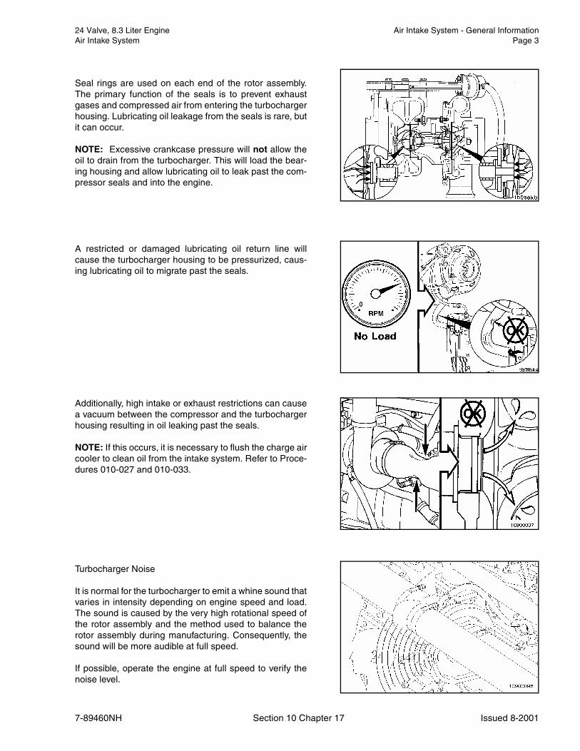
Seal rings are used on each end of the rotor assembly.The primary function of the seals is to prevent exhaustgases and compressed air from entering the turbochargerhousing. Lubricating oil leakage from the seals is rare, butit can occur.
NOTE: Excessive crankcase pressure will not allow theoil to drain from the turbocharger. This will load the bear-ing housing and allow lubricating oil to leak past the com-pressor seals and into the engine.
A restricted or damaged lubricating oil return line willcause the turbocharger housing to be pressurized, caus-ing lubricating oil to migrate past the seals.
Additionally, high intake or exhaust restrictions can causea vacuum between the compressor and the turbochargerhousing resulting in oil leaking past the seals.
NOTE: If this occurs, it is necessary to flush the charge aircooler to clean oil from the intake system. Refer to Proce-dures 010-027 and 010-033.
Turbocharger Noise
It is normal for the turbocharger to emit a whine sound thatvaries in intensity depending on engine speed and load.The sound is caused by the very high rotational speed ofthe rotor assembly and the method used to balance therotor assembly during manufacturing. Consequently, thesound will be more audible at full speed.
If possible, operate the engine at full speed to verify thenoise level.
Air Intake System - General Information 24 Valve, 8.3 Liter EnginePage 4 Air Intake System
7-89460NH Section 10 Chapter 17 Issued 8-2001
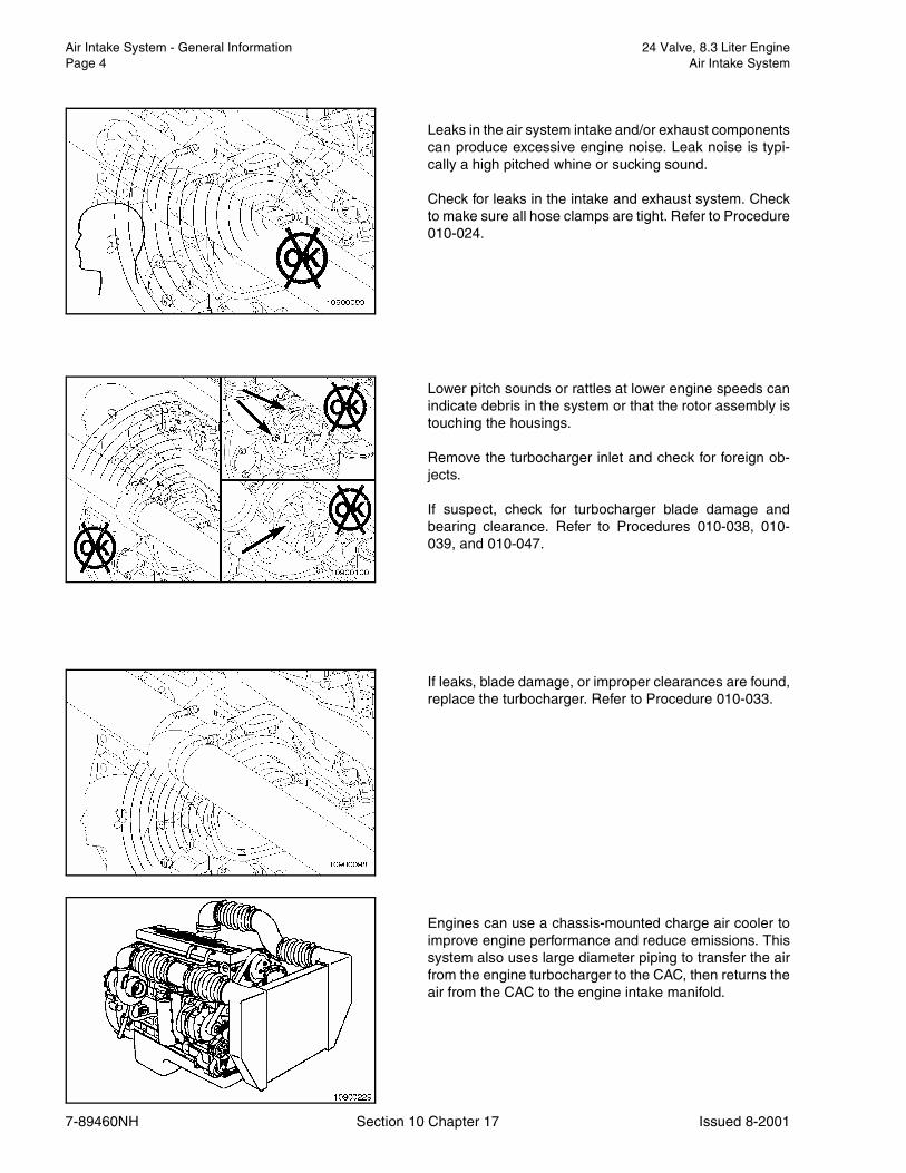
Leaks in the air system intake and/or exhaust componentscan produce excessive engine noise. Leak noise is typi-cally a high pitched whine or sucking sound.
Check for leaks in the intake and exhaust system. Checkto make sure all hose clamps are tight. Refer to Procedure010-024.
Lower pitch sounds or rattles at lower engine speeds canindicate debris in the system or that the rotor assembly istouching the housings.
Remove the turbocharger inlet and check for foreign ob-jects.
If suspect, check for turbocharger blade damage andbearing clearance. Refer to Procedures 010-038, 010-039, and 010-047.
If leaks, blade damage, or improper clearances are found,replace the turbocharger. Refer to Procedure 010-033.
Engines can use a chassis-mounted charge air cooler toimprove engine performance and reduce emissions. Thissystem also uses large diameter piping to transfer the airfrom the engine turbocharger to the CAC, then returns theair from the CAC to the engine intake manifold.

24 Valve, 8.3 Liter Engine Flow Diagram, Air In take SystemAir Intake System Page 5
7-89460NH Section 10 Chapter 17 Issued 8-2001
Flow Diagram, Air In take System
1. Intake Air Inlet to Turbocharger2. Turbocharger Air to Charge Air Cooler3. Charge Air Cooler4. Intake Manifold (Integral Part of Cylinder Head)5. Intake Valve
Specifications 24 Valve, 8.3 Liter EnginePage 6 Air Intake System
7-89460NH Section 10 Chapter 17 Issued 8-2001
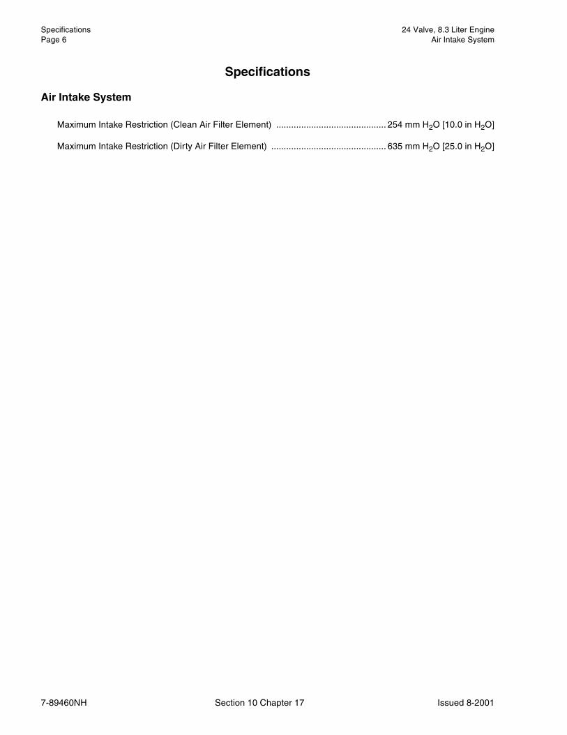
Specifications
Air Intake System
Maximum Intake Restriction (Clean Air Filter Element) ............................................ 254 mm H2O [10.0 in H2O]
Maximum Intake Restriction (Dirty Air Filter Element) .............................................. 635 mm H2O [25.0 in H2O]

24 Valve, 8.3 Liter Engine Air Crossover (010-019)Air Intake System Page 7
7-89460NH Section 10 Chapter 17 Issued 8-2001
Air Crossover (010-019)
Remove (010-019-002)
8 mm or Screwdriver
Loosen the hose clamps and position the crossover tubeso that it can be removed.
Remove the tube.
Inspect for Reuse (010-019-007)
Check the crossover tube for cracks, holes, and worn sec-tions. Replace with a new hose and clamps if necessary.
Install (010-019-026)
8 mm or Screwdriver
Install the crossover tube and clamps in the reverse orderof removal.
Tighten the clamps.
Torque Value: 5 N•m [44 in-lb]
Air Inlet Connection (010-022)
Remove (010-022-002)
8 mm
Loosen air inlet clamps.
Remove the air inlet connection.

Air Intake Manifold (010-023) 24 Valve, 8.3 Liter EnginePage 8 Air Intake System
7-89460NH Section 10 Chapter 17 Issued 8-2001
Install (010-019-026)
Install the air inlet connection.
Tighten air inlet clamps.
Run engine and check for leaks.
Air Intake Manifold (010-023)
Preparatory (010-023-000)
Disconnect the cold starting aid, if used.
Remove the cooler air crossover tube, if used.
Disconnect the charged air cooler hose, if used.
Remove the air intake connection.
Remove (010-023-002)
Remove the injector supply lines. Refer to Procedure 006-051.
Remove the mounting capscrews and the intake cover.
Tape off the intake manifold opening to prevent debrisfrom entering the intake system.
NOTE: Be sure not to tape over the entire manifold edgesso that the surface can be cleaned.

24 Valve, 8.3 Liter Engine Air Intake Manifold (010-023)Air Intake System Page 9
7-89460NH Section 10 Chapter 17 Issued 8-2001
Clean (010-023-006)
Clean the sealing surfaces.
Keep the gasket material and any other material out of theair intake.
Inspect for Reuse (010-023-007)
Remove the tape.
Inspect the intake manifold for cracks or other damage.
NOTE: When inspecting the intake manifold for oil or de-bris from an air system failure, also inspect the cylinderhead for oil and debris.
Install (010-023-026)
Install the cover with intake air heater (if equipped) and anew gasket.
Torque Value: 24 N•m [18 ft-lb]
NOTE: Some capscrews shared with fuel line braces.
Install the injector supply line. Refer to Procedure 006-051.

Air Leaks, Air Intake and Exhaust Systems (010-024) 24 Valve, 8.3 Liter EnginePage 10 Air Intake System
7-89460NH Section 10 Chapter 17 Issued 8-2001
Install the air intake connections, including new gaskets.
Connect the charge air cooler hose.
Install the air crossover tube.
Air Leaks, Air Intake and Exhaust Systems (010-024)
Initial Check (010-024-001)
Leaks in the intake air system are most commonly identi-fied by:1. Inspection of piping for cracked or loose clamps.2. Applying a solution of soapy water in the suspected
area and inspecting for bubbles.3. Listening for high pitch whining or sucking sound in
the suspected area.
� CAUTION �Engine intake air must be filtered to prevent dirt anddebris from entering the engine. If intake air piping isdamaged or loose, unfiltered air will enter the engineand cause premature wear.

24 Valve, 8.3 Liter Engine Air Leaks, Air Intake and Exhaust Systems (010-024)Air Intake System Page 11
7-89460NH Section 10 Chapter 17 Issued 8-2001
Inspect the inlet air piping for cracked hoses and damagedor loose clamps.
Operate the engine at high idle and use a solution ofsoapy water to spot intake air leaks.
If an air leak exists, the soap bubbles will be drawn in withthe air.
Replace damaged pipes and tighten loose clamps tomake sure the air inlet system does not leak.
Torque Value: 8 N•m [71 in-lb]
Check for corrosion of the inlet system piping under theclamps and hoses. Corrosion can allow corrosive prod-ucts and dirt to enter the intake system.
Disassemble and clean as required.
Pressure Side Intake System
Leaks in the intake system will reduce the amount of air tothe cylinders during engine operation and decrease en-gine performance.
Operate the engine at full throttle and rated rpm with max-imum load.
Apply soapy water solution to sealing surfaces and in-spect for bubbles. Bubbles should be easy to detect.

Air Leaks, Air Intake and Exhaust Systems (010-024) 24 Valve, 8.3 Liter EnginePage 12 Air Intake System
7-89460NH Section 10 Chapter 17 Issued 8-2001
Leaks may also be found at the turbo outlet connection.
Inspect for damage, replace sealing o-ring, and tightenloose clamps.
Leaks may also be found at the turbo outlet connection.
Inspect for damage, replace sealing o-ring, and tightenloose clamps.
Torque Value: 8 N•m [71 in-lb]
Any Charge Air Cooler Tubing or Connecting Hoses
Inspect the hose and tubing for damage.
Tighten loose clamps.
Torque Value: 8 N•m [71 in-lb]
Intake Manifold Connection
Inspect for damage.
Tighten loose clamps.
Replace the gasket. Refer to Procedure 010-023.

24 Valve, 8.3 Liter Engine Air Leaks, Air Intake and Exhaust Systems (010-024)Air Intake System Page 13
7-89460NH Section 10 Chapter 17 Issued 8-2001
Intake Manifold
Inspect for damage.
Replace the gasket. Refer to Procedure 010-023.
Wastegate Capsule/Plumbing
Inspect for damage.
Compressor Housing Sealing Surface
Inspect for damage.
Clean surface.
Exhaust System
Leaks in the exhaust system will cause the turbo to oper-ate at a lower speed, reducing the amount of air going tothe cylinders during engine operation.

Air Leaks, Air Intake and Exhaust Systems (010-024) 24 Valve, 8.3 Liter EnginePage 14 Air Intake System
7-89460NH Section 10 Chapter 17 Issued 8-2001
Operate the engine at full throttle and rated rpm with max-imum load.
Leaks can be identified by noise, soapy water, or discolor-ation caused by the escaping hot gases.
Inspect the exhaust manifold gaskets for leaks.
Inspect the turbocharger mounting gaskets for leaks.
Inspect the turbine housing sealing surface for leaks.

24 Valve, 8.3 Liter Engine Charge Air Cooler (CAC) (010-027)Air Intake System Page 15
7-89460NH Section 10 Chapter 17 Issued 8-2001
Operate the engine at full throttle and rated rpm with max-imum load.
Listen and inspect again for leaks.
Charge Air Cooler (CAC) (010-027)
Clean (010-027-006)
If the engine experiences a turbocharger failure or anyother occasion where oil or debris is put into the chargeair cooler (CAC), the CAC must be cleaned.
Remove the CAC piping and CAC from the vehicle.
� CAUTION �Do not use caustic cleaners to clean the CAC. Dam-age to the CAC will result.
Flush the CAC internally with solvent in the opposite direc-tion of normal air flow. Shake the CAC and lightly tap onthe end tanks with a rubber mallet to dislodge trapped de-bris. Continue flushing until all debris or oil is removed(i.e., the water runs clear).
NOTE: Make sure that the tubes are in the vertical direc-tion when flushing.
If the debris can not be totally removed from the CAC, theCAC must be replaced.
After the CAC has been thoroughly cleaned of all oil anddebris with solvent, wash the CAC internally with hotsoapy water to remove the remaining solvent. Rinse thor-oughly with clean water.
� CAUTION �The CAC must be rinsed, dried, and free of solvent,oil, and debris, or engine damage will result.
Blow compressed air through the inside of the CAC in theopposite direction of normal air flow until the CAC is dryinternally.

Cold Starting Aid (010-029) 24 Valve, 8.3 Liter EnginePage 16 Air Intake System
7-89460NH Section 10 Chapter 17 Issued 8-2001
Inspect for Reuse (010-027-007)
Inspect the CAC for cracks, holes, or damage.
Inspect the tubes, fins, and welds for tears, breaks, or oth-er damage. If any damage causes the CAC to fail the airleak check, the CAC must be replaced. Refer to Proce-dure 010-024.
Install the CAC and CAC piping on the vehicle.
Always clean and inspect the CAC piping and hoses priorto installation.
Cold Starting Aid (010-029)
Remove (010-029-002)
If equipped, remove charge air cooler (CAC) plumbing.
Disconnect grid heater wiring.
Remove the air intake connection.
Remove high pressure fuel lines. Refer to Procedure 006-051.
Remove intake air heater assembly. Refer to Procedure010-022.
If the grid heater is to be removed for any length of time,apply tape over the hole to keep debris out of the air in-take.
24 Valve, 8.3 Liter Engine Air Intake Restriction (010-031)Air Intake System Page 17
7-89460NH Section 10 Chapter 17 Issued 8-2001
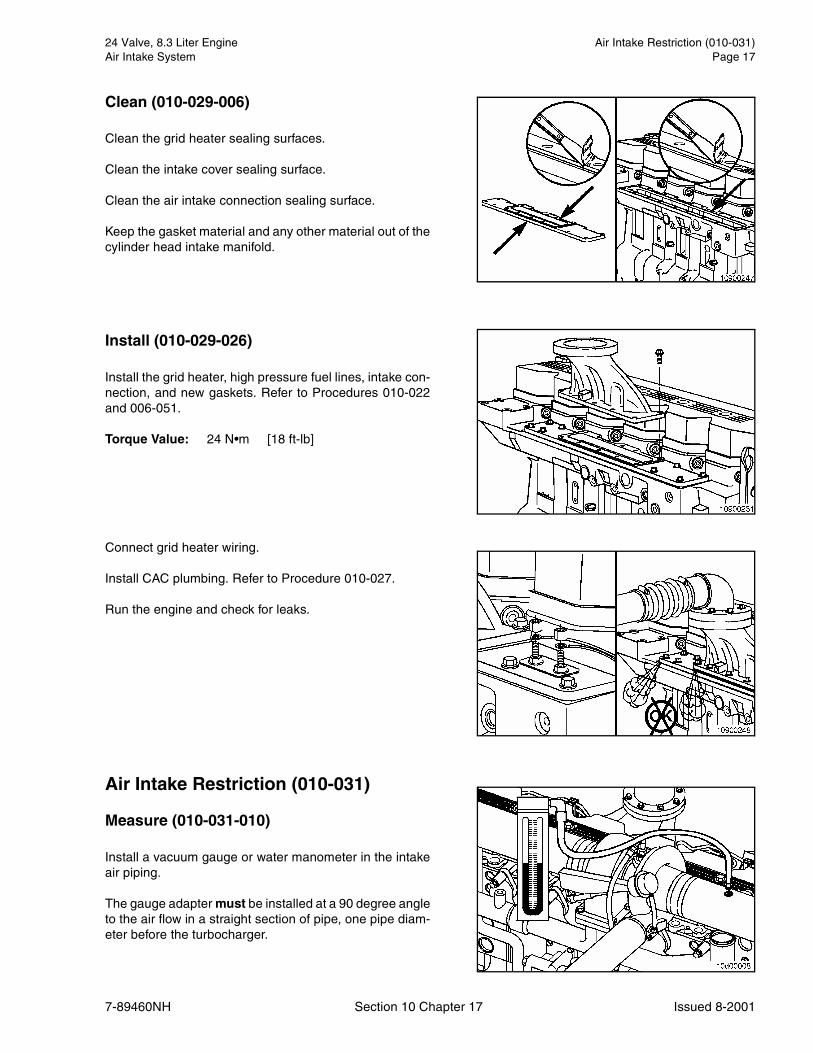
Clean (010-029-006)
Clean the grid heater sealing surfaces.
Clean the intake cover sealing surface.
Clean the air intake connection sealing surface.
Keep the gasket material and any other material out of thecylinder head intake manifold.
Install (010-029-026)
Install the grid heater, high pressure fuel lines, intake con-nection, and new gaskets. Refer to Procedures 010-022and 006-051.
Torque Value: 24 N•m [18 ft-lb]
Connect grid heater wiring.
Install CAC plumbing. Refer to Procedure 010-027.
Run the engine and check for leaks.
Air Intake Restriction (010-031)
Measure (010-031-010)
Install a vacuum gauge or water manometer in the intakeair piping.
The gauge adapter must be installed at a 90 degree angleto the air flow in a straight section of pipe, one pipe diam-eter before the turbocharger.
Air Intake Restriction (010-031) 24 Valve, 8.3 Liter EnginePage 18 Air Intake System
7-89460NH Section 10 Chapter 17 Issued 8-2001
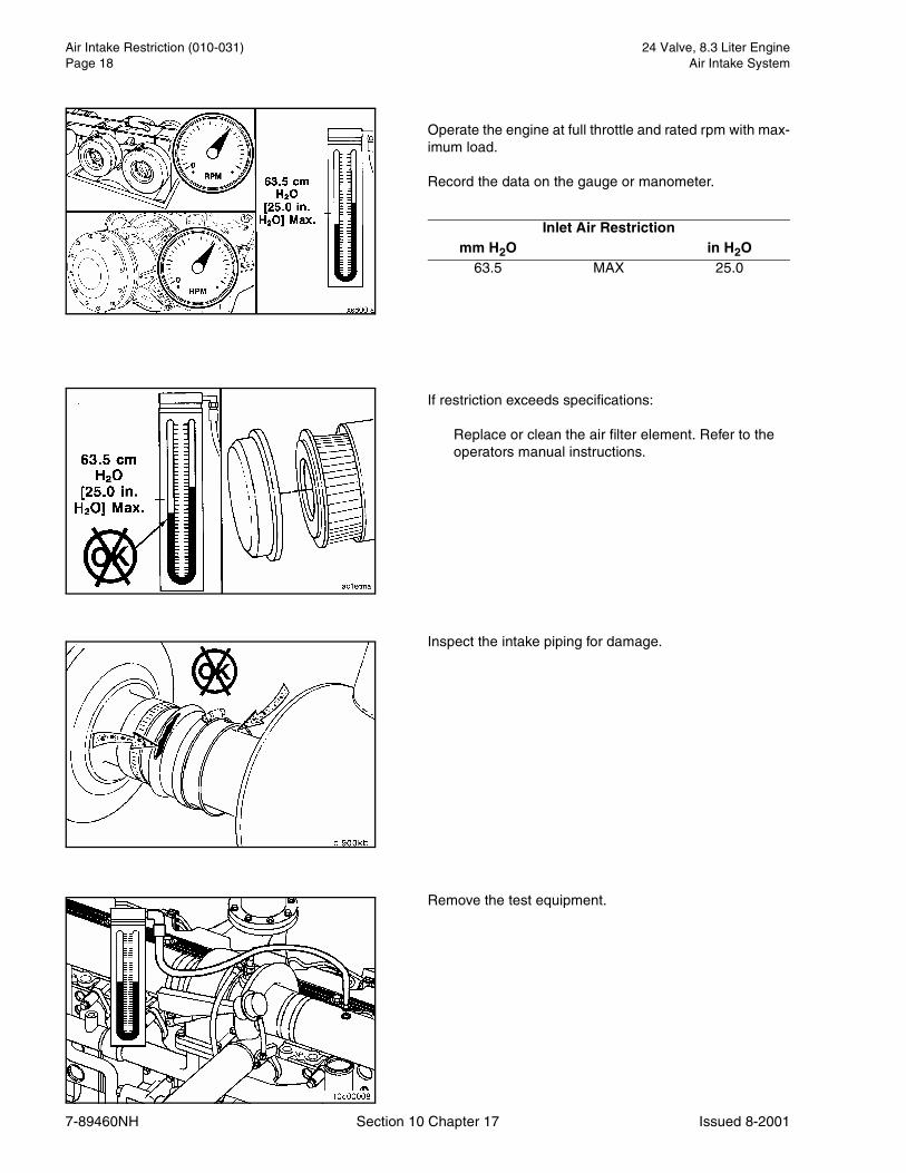
Operate the engine at full throttle and rated rpm with max-imum load.
Record the data on the gauge or manometer.
If restriction exceeds specifications:
Replace or clean the air filter element. Refer to the operators manual instructions.
Inspect the intake piping for damage.
Remove the test equipment.
Inlet Air Restrictionmm H2O in H2O
63.5 MAX 25.0

24 Valve, 8.3 Liter Engine Turbocharger (010-033)Air Intake System Page 19
7-89460NH Section 10 Chapter 17 Issued 8-2001
Turbocharger (010-033)
Remove (010-033-002)
Remove the intake and exhaust pipes from the turbo-charger.
Remove the oil supply line from the turbocharger.
Remove the oil drain line from the turbocharger.
Remove the v-band clamp, discharge elbow and o-ringfrom the turbocharger compressor discharge outlet.
Remove the four turbocharger mounting nuts.
Remove the turbocharger and gasket.
NOTE: If the turbocharger is not to be immediately re-placed, cover the opening to prevent any material fromfalling into the manifold.

Turbocharger (010-033) 24 Valve, 8.3 Liter EnginePage 20 Air Intake System
7-89460NH Section 10 Chapter 17 Issued 8-2001
Clean (010-033-006)
Clean the turbocharger and exhaust manifold gasket sur-faces.
Inspect for Reuse (010-033-007)
Inspect the turbocharger and exhaust manifold gasketsurfaces, and mounting studs for cracks and damage.
Inspect the turbine and compressor housings.
If cracks that go all the way through the outer walls arefound, the housing must be replaced.
NOTE: A charge air cooler failure can cause progressivedamage to the turbine housing. If the turbine housing isdamaged, check the charge air cooler. Refer to Procedure010-027.
Cracks in the mounting flange longer than 15 mm [0.6 in]are not acceptable.

24 Valve, 8.3 Liter Engine Turbocharger (010-033)Air Intake System Page 21
7-89460NH Section 10 Chapter 17 Issued 8-2001
Cracks of any length that reach mounting holes are notacceptable.
Two cracks must be separated by at least 6.4 mm [0.25in].
Cracks in the divider are acceptable only if they are sepa-rated by at least 12.5 mm [0.50 in].
NOTE: If the engine experiences a turbocharger failure orany other occasion where oil or debris is put into thecharge air system, the charge air system must be inspect-ed and cleaned. Refer to Procedures 010-027 and 010-023.
Turbocharger (010-033) 24 Valve, 8.3 Liter EnginePage 22 Air Intake System
7-89460NH Section 10 Chapter 17 Issued 8-2001
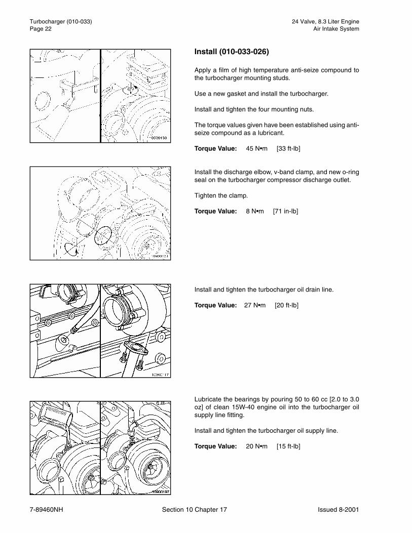
Install (010-033-026)
Apply a film of high temperature anti-seize compound tothe turbocharger mounting studs.
Use a new gasket and install the turbocharger.
Install and tighten the four mounting nuts.
The torque values given have been established using anti-seize compound as a lubricant.
Torque Value: 45 N•m [33 ft-lb]
Install the discharge elbow, v-band clamp, and new o-ringseal on the turbocharger compressor discharge outlet.
Tighten the clamp.
Torque Value: 8 N•m [71 in-lb]
Install and tighten the turbocharger oil drain line.
Torque Value: 27 N•m [20 ft-lb]
Lubricate the bearings by pouring 50 to 60 cc [2.0 to 3.0oz] of clean 15W-40 engine oil into the turbocharger oilsupply line fitting.
Install and tighten the turbocharger oil supply line.
Torque Value: 20 N•m [15 ft-lb]

24 Valve, 8.3 Liter Engine Turbocharger Axial Clearance (010-038)Air Intake System Page 23
7-89460NH Section 10 Chapter 17 Issued 8-2001
Rotate the compressor housing to fit intake pipes, if nec-essary. Use the snap ring to make necessary adjust-ments.
Install the intake pipe and tighten the clamp.
Install the exhaust pipe and tighten the clamp.
Torque Value: 8 N•m [71 in-lb]
Operate the engine and check for air leaks.
Turbocharger Axial Clearance (010-038)
Measure (010-038-010)
Remove exhaust and intake piping.
Push the rotor assembly away from the gauge.
Set the gauge on zero (0).
Push the rotor assembly toward the gauge and record thereading.
Replace the turbocharger if the clearance does not meetthe specifications. Refer to Procedure 010-033.
Install the exhaust pipe and tighten the clamp.
Install the intake pipe and tighten the clamp.
Torque Value: 8 N•m [71 in-lb]
Axial Clearancemm in
0.038 MIN 0.00150.089 MAX 0.0035

Turbocharger Blade Damage (010-039) 24 Valve, 8.3 Liter EnginePage 24 Air Intake System
7-89460NH Section 10 Chapter 17 Issued 8-2001
Turbocharger Blade Damage (010-039)
Inspect for Reuse (010-039-007)
Remove the intake pipe from the turbocharger.
Inspect the turbocharger compressor impeller blades fordamage.
Replace the turbocharger if damage is found. Refer toProcedure 010-033.
If the compressor impeller is damaged, inspect the intakepiping and filter element for damage.
Repair any damage before operating the engine.
Remove the exhaust pipe from the turbocharger.
Inspect the turbine wheel for damage.
Replace the turbocharger if damage is found. Refer toProcedure 010-033.
Install the intake pipe and tighten the clamp.
Install the exhaust pipe and tighten the clamp.
Torque Value: 8 N•m [71 in-lb]

24 Valve, 8.3 Liter Engine Turbocharger Compressor Seal Leaks (010-040)Air Intake System Page 25
7-89460NH Section 10 Chapter 17 Issued 8-2001
Turbocharger Compressor Seal Leaks (010-040)
Leak Test (010-040-014)
Remove the air intake and CAC piping from the turbo-charger.
Inspect the compressor intake and discharge for oil.
If oil is present in the compressor intake as well as in thedischarge, check upstream in the turbocharger for thesource of the oil.
If oil is present only in the discharge side, install the air in-take and CAC piping.
Check for intake restriction. Refer to Procedure 010-031.
If no intake restriction is found, replace the turbocharger.Refer to Procedure 010-033.
NOTE: If the engine experiences a turbocharger failure orany other occasion where oil is put into the charge air sys-tem, the charge air system must be inspected andcleaned. Refer to Procedures 010-027 and 010-023.
Turbocharger Oil Drain Line (010-045)
Initial Check (010-045-001)
Inspect the turbocharger oil drain line for oil leaks or dam-age.
Repair as necessary.

Turbocharger Oil Drain Line (010-045) 24 Valve, 8.3 Liter EnginePage 26 Air Intake System
7-89460NH Section 10 Chapter 17 Issued 8-2001
Remove (010-045-002)
Remove the capscrews from the oil drain tube.
Pull the drain line out of the drain line boss.
Clean (010-045-006)
Clean the gasket sealing surfaces (first frame).
Clean the o-ring seating bore and make sure it is free ofdirt and debris (second frame).
Inspect for Reuse (010-045-007)
Inspect the line for cracks, wear, and damage.
Inspect the o-ring for fretting and cracking. Replace if nec-essary.
Check the rubber section of the drain line for deterioration.
Install (010-045-026)
Apply a thin film of oil to the drain line o-rings.
Push the drain line into the drain line boss. Be sure botho-rings are completely seated in the bore.
Install the drain line capscrews with a new gasket.
Operate the engine and check for leaks.

24 Valve, 8.3 Liter Engine Turbocharger Oil Supply Line (010-046)Air Intake System Page 27
7-89460NH Section 10 Chapter 17 Issued 8-2001
Turbocharger Oil Supply Line (010-046)
Initial Check (010-046-001)
Inspect the line for oil leaks or damage. Replace if neces-sary.
Remove (010-046-002)
Remove the oil supply line from the turbo bearing housing(1).
Remove the oil supply line from the oil filter head (2).
Inspect for Reuse (010-046-007)
Inspect the line for cracks, wear, and damage.
Inspect o-rings for cracking and fretting. Replace if neces-sary.
Install (010-046-026)
Apply a thin film of oil to the o-ring seals.
Fill the turbo oil inlet with clean oil.
Install a line at both the filter head and the turbo bearinghousing, then hand tighten.
Tighten the line to final torque.
Torque Value: 24 N•m [18 ft-lb]
Turbocharger Radial Bearing Clearance (010-047) 24 Valve, 8.3 Liter EnginePage 28 Air Intake System
7-89460NH Section 10 Chapter 17 Issued 8-2001
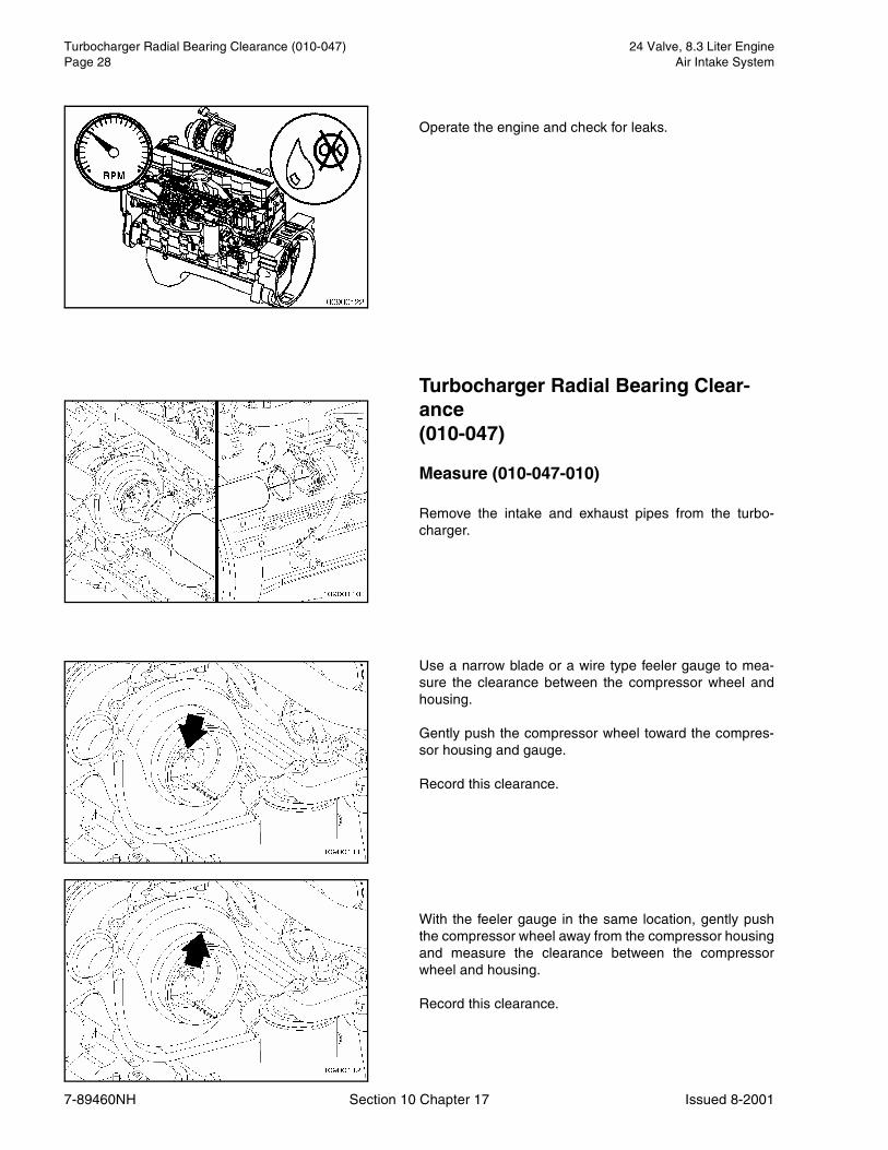
Operate the engine and check for leaks.
Turbocharger Radial Bearing Clear-ance(010-047)
Measure (010-047-010)
Remove the intake and exhaust pipes from the turbo-charger.
Use a narrow blade or a wire type feeler gauge to mea-sure the clearance between the compressor wheel andhousing.
Gently push the compressor wheel toward the compres-sor housing and gauge.
Record this clearance.
With the feeler gauge in the same location, gently pushthe compressor wheel away from the compressor housingand measure the clearance between the compressorwheel and housing.
Record this clearance.
24 Valve, 8.3 Liter Engine Turbocharger Wastegate Actuator (010-050)Air Intake System Page 29
7-89460NH Section 10 Chapter 17 Issued 8-2001
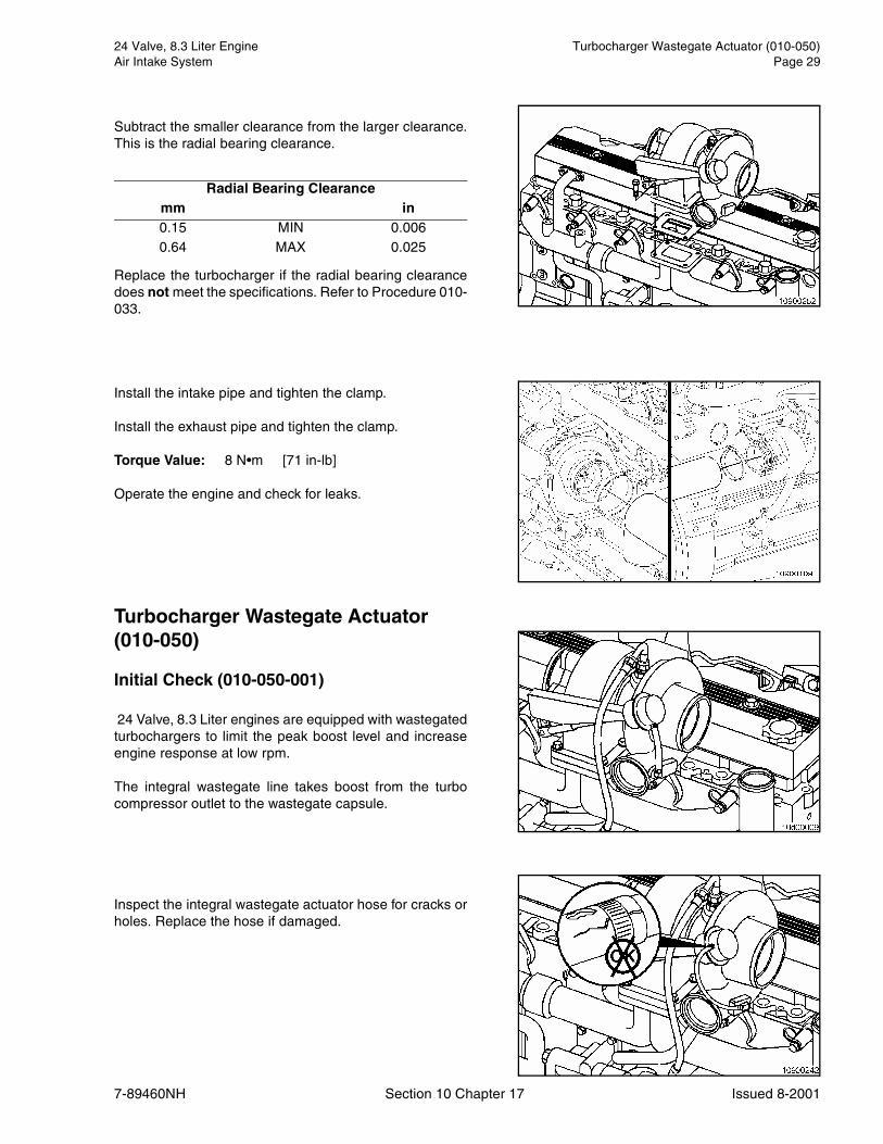
Subtract the smaller clearance from the larger clearance.This is the radial bearing clearance.
Replace the turbocharger if the radial bearing clearancedoes not meet the specifications. Refer to Procedure 010-033.
Install the intake pipe and tighten the clamp.
Install the exhaust pipe and tighten the clamp.
Torque Value: 8 N•m [71 in-lb]
Operate the engine and check for leaks.
Turbocharger Wastegate Actuator (010-050)
Initial Check (010-050-001)
24 Valve, 8.3 Liter engines are equipped with wastegatedturbochargers to limit the peak boost level and increaseengine response at low rpm.
The integral wastegate line takes boost from the turbocompressor outlet to the wastegate capsule.
Inspect the integral wastegate actuator hose for cracks orholes. Replace the hose if damaged.
Radial Bearing Clearancemm in 0.15 MIN 0.0060.64 MAX 0.025

Turbocharger Wastegate Actuator (010-050) 24 Valve, 8.3 Liter EnginePage 30 Air Intake System
7-89460NH Section 10 Chapter 17 Issued 8-2001
Inspect the wastegate mounting bracket, actuator rod,and lever for damage. A bent wastegate mounting brack-et, actuator rod, or lever can cause improper operation.
If the wastegate mounting bracket, actuator rod, or lever isbent, it must be replaced.
Test (010-050-012)
NOTE: In some applications the turbocharger must be re-moved to test the wastegate actuator. Refer to Procedure010-033.
Disconnect the integral boost line from the wastegate cap-sule.
Attach a dial indicator (1) as shown, so that its shaft is inline with the wastegate actuator rod. Set the indicator tozero.
Connect clean regulated air pressure and a pressuregauge to the capsule. Apply 200 kPa [29 psi] to make surethe wastegate is functioning properly.
The rod should move approximately 0.5 to 1.04 mm [0.20to 0.41 in] without any sticking or air leakage.
NOTE: No air should be heard such as leak noise througha functional wastegate capsule.
NOTE: A small amount of travel when air pressure is firstapplied is normal. The tolerance is being removed fromthe system.
Replace the turbocharger if no movement of the actuatorrod and lever is detected.

24 Valve, 8.3 Liter Engine Turbocharger Wastegate Valve Body (010-055)Air Intake System Page 31
7-89460NH Section 10 Chapter 17 Issued 8-2001
Turbocharger Wastegate Valve Body (010-055)
Maintenance Check (010-055-008)
Inspect the lever pin.
Replace the turbine housing assembly if worn excessively.
Inspect the valve and valve seat for cracks or erosion.
Replace the turbine housing assembly if worn excessively.
Boost Pressure (010-057)
Measure (010-057-010)
Measure boost pressure at the intake manifold by usingan electronic service tool for hookup and monitoring pro-cedures.
Boost Pressure (010-057) 24 Valve, 8.3 Liter EnginePage 32 Air Intake System
7-89460NH Section 10 Chapter 17 Issued 8-2001